Capillary optical fiber – design, fabrication, characterization and ...
16
BULLETIN OF THE POLISH ACADEMY OF SCIENCES TECHNICAL SCIENCES Vol. 56, No. 2, 2008 Capillary optical fiber – design, fabrication, characterization and application R. ROMANIUK * Institute of Electronic Systems, Warsaw University of Technology, 15/19 Nowowiejska St., 00-665 Warsaw, Poland Abstract. The paper presents a modification of capillary optical fibers fabrication method from an assembled glass preform. A change of dimensional proportions in the capillary optical fiber drawn from a single preform is allowed on-line via the control of overpressure and thermal conditions in the outflow meniscus which essentially lowers the manufacturing costs. These conditions are among the solutions (velocity fields) of the Navier-Stokes equations adapted to the capillary optical fiber pulling geometry and temperature distribution in the oven. The velocity fields give solutions to other quantities of interest such as flow rate, pulling force and fiber geometry. The calculation and experimental results for capillary optical fibers were shown in the following dimensional range: internal diameters 2-200 μm, external diameters 30–350 μm, within the assumed dimensional stability (including ellipticity) better than 1%. The parameters of fabricated capillary optical fibers of high-quality low-loss optical multicomponent glasses were: losses¡100 dB/km, mechanical strength above 1GPa with Weibull coefficient in the range 3–7, internal numerical aperture 0.1–0.3, external numerical aperture 0.1–0.3, core index 1.5–1.8, transparency 0.4–2 μm, thermally and/or chemically conditioned internal surface, double polyimide protection layer, soft or hard jacketed, connectorized. The capillary optical fibers were applied in our own and several external laboratories in spectroscopy, refractometry, micro-fluidics and functional microoptic components. The paper summarizes a design, technological and application work on capillary optical fibers performed during a recent national research program devoted to optoelectronic components and modules. Key words: capillary optical fibers, optical fiber technology, hollow core optical fibers, optoelectronics 1. Introduction A capillary optical fiber (COF) consists of an annular, ring- like, doughnut-shaped, high-index optical core around an air hole, a low-index optical cladding and a protective, high-index polymer jacket (coating). Optical wave propagation in a cap- illary depends essentially on the geometrical distribution of empty areas in the cross section of the fiber and refractive in- dex distribution near glass-air boundary. Refractive structure of the cladding is uniform or has an index depression around the core. Capillary optical fibers are low-loss optical glass [1], or amorphous polymer, multilayer filaments in which uniquely the wave [2] and matter [3] can be simultaneously propagated likewise and counter wise. The axial hole in a COF is per- fectly circular, quasi-circular (multiangular) or with periodic, angularly distributed surface artifacts, in a photonic COF – for removal of surface modes, elliptical, square or complex. The axial hole in COF is longitudinally uniform, linearly of exponentially tapered for fiber to fiber coupling, optical pow- er focusing, mode conversion, periodically or aperiodically wrinkled for modal radiation characteristics design between fiber layers. The empty core is evacuated or filled with an active medi- um as vapor, water, gas – like hydrogen or methane [4], liquid [5], liquid crystal, self-assembling colloidal crystal or stream of single, cold, optically guided rather than ballistic particles – like atoms, molecules or nanocrystallites. The aim of filling the hollow core is to confine the interaction between the wave and matter to a minute area in the cross section but of considerable optical length in the capillary. The interaction processes get amplified many orders of magnitude by big op- tical gradients (not necessarily by the intensity alone) and the path. The internal surface of COF is pure pristine glass – left isolated in vacuum from the very moment of fiber manufactur- ing, conditioned glass – either silanized, hydrated, processed for passivation of unbound oxygen bridges, or lined with a va- riety of immobilized activating thin-film layers including elec- trostatically self-aligning layers of high adhesion [6]. The aim of conditioning or lining of the internal capillary surface is to prepare it to the role of a reaction base, immobilizing matrix or catalyst between different interacting streams of matter and wave. After the reaction and optical measurement, the lining layer is to be developed, polymerized, chemically or optically modified, partially or completely washed out, to prepare the inner surface of COF for the same, changed or a different process. Propagation characteristics of the COF, including single- mode or multimode, guided or weakly-leaking modes, depend on the state of internal surface of the fiber, relative dimensions of the hollow core to the wavelength and refractive/diffractive structure of glass, and other dielectric – like polyolefines, semiconductor – like germanium, or noble metal layers [7] encircling the core. A large difference of indexes on the in- ternal air-glass boundary in the optical core of COF causes * e-mail: elka.pw.edu.pl 87
-
Upload
truongcong -
Category
Documents
-
view
222 -
download
1
Transcript of Capillary optical fiber – design, fabrication, characterization and ...
BULLETIN OF THE POLISH ACADEMY OF SCIENCES
TECHNICAL SCIENCES
Vol. 56, No. 2, 2008
Capillary optical fiber – design, fabrication, characterization
and application
R. ROMANIUK∗
Institute of Electronic Systems, Warsaw University of Technology,
15/19 Nowowiejska St., 00-665 Warsaw, Poland
Abstract. The paper presents a modification of capillary optical fibers fabrication method from an assembled glass preform. A change of
dimensional proportions in the capillary optical fiber drawn from a single preform is allowed on-line via the control of overpressure and
thermal conditions in the outflow meniscus which essentially lowers the manufacturing costs. These conditions are among the solutions
(velocity fields) of the Navier-Stokes equations adapted to the capillary optical fiber pulling geometry and temperature distribution in the
oven. The velocity fields give solutions to other quantities of interest such as flow rate, pulling force and fiber geometry. The calculation
and experimental results for capillary optical fibers were shown in the following dimensional range: internal diameters 2-200 µm, external
diameters 30–350 µm, within the assumed dimensional stability (including ellipticity) better than 1%. The parameters of fabricated capillary
optical fibers of high-quality low-loss optical multicomponent glasses were: losses¡100 dB/km, mechanical strength above 1GPa with Weibull
coefficient in the range 3–7, internal numerical aperture 0.1–0.3, external numerical aperture 0.1–0.3, core index 1.5–1.8, transparency
0.4–2 µm, thermally and/or chemically conditioned internal surface, double polyimide protection layer, soft or hard jacketed, connectorized.
The capillary optical fibers were applied in our own and several external laboratories in spectroscopy, refractometry, micro-fluidics and
functional microoptic components. The paper summarizes a design, technological and application work on capillary optical fibers performed
during a recent national research program devoted to optoelectronic components and modules.
Key words: capillary optical fibers, optical fiber technology, hollow core optical fibers, optoelectronics
1. Introduction
A capillary optical fiber (COF) consists of an annular, ring-
like, doughnut-shaped, high-index optical core around an air
hole, a low-index optical cladding and a protective, high-index
polymer jacket (coating). Optical wave propagation in a cap-
illary depends essentially on the geometrical distribution of
empty areas in the cross section of the fiber and refractive in-
dex distribution near glass-air boundary. Refractive structure
of the cladding is uniform or has an index depression around
the core. Capillary optical fibers are low-loss optical glass [1],
or amorphous polymer, multilayer filaments in which uniquely
the wave [2] and matter [3] can be simultaneously propagated
likewise and counter wise. The axial hole in a COF is per-
fectly circular, quasi-circular (multiangular) or with periodic,
angularly distributed surface artifacts, in a photonic COF –
for removal of surface modes, elliptical, square or complex.
The axial hole in COF is longitudinally uniform, linearly of
exponentially tapered for fiber to fiber coupling, optical pow-
er focusing, mode conversion, periodically or aperiodically
wrinkled for modal radiation characteristics design between
fiber layers.
The empty core is evacuated or filled with an active medi-
um as vapor, water, gas – like hydrogen or methane [4],
liquid [5], liquid crystal, self-assembling colloidal crystal or
stream of single, cold, optically guided rather than ballistic
particles – like atoms, molecules or nanocrystallites. The aim
of filling the hollow core is to confine the interaction between
the wave and matter to a minute area in the cross section but
of considerable optical length in the capillary. The interaction
processes get amplified many orders of magnitude by big op-
tical gradients (not necessarily by the intensity alone) and the
path.
The internal surface of COF is pure pristine glass – left
isolated in vacuum from the very moment of fiber manufactur-
ing, conditioned glass – either silanized, hydrated, processed
for passivation of unbound oxygen bridges, or lined with a va-
riety of immobilized activating thin-film layers including elec-
trostatically self-aligning layers of high adhesion [6]. The aim
of conditioning or lining of the internal capillary surface is to
prepare it to the role of a reaction base, immobilizing matrix
or catalyst between different interacting streams of matter and
wave. After the reaction and optical measurement, the lining
layer is to be developed, polymerized, chemically or optically
modified, partially or completely washed out, to prepare the
inner surface of COF for the same, changed or a different
process.
Propagation characteristics of the COF, including single-
mode or multimode, guided or weakly-leaking modes, depend
on the state of internal surface of the fiber, relative dimensions
of the hollow core to the wavelength and refractive/diffractive
structure of glass, and other dielectric – like polyolefines,
semiconductor – like germanium, or noble metal layers [7]
encircling the core. A large difference of indexes on the in-
ternal air-glass boundary in the optical core of COF causes
∗e-mail: elka.pw.edu.pl
87

R. Romaniuk
that the fundamental mode LP01 (contrary to a classical, step-
index singlemode optical fiber) may have a finite value of the
cut-off frequency. Cut-off of the fundamental mode in COF
(similarly to W-profile and M-profile optical fibers) depends
on the fiber construction. The condition for a fundamental
mode to possess a nonzero cut-off frequency in a singlemode
COF is that the average value of the refraction in the core area
(embracing optical core and a hole) has to be lower than the
average refraction in the cladding. The area of this property is
called a negative dielectric volume [8]. Existence of a nonze-
ro cut-off for the fundamental mode makes from such a COF
a tunable distributed modal filter. The filter is fabricated in
practice of a tapered length of a fiber. When the COF core is
elliptical or distorted cylindrical, the fiber displays birefrin-
gence and polarization maintaining capability.
The fundamental, singlemode, ring-like, dark hollow beam
of light (DHB) of zero intensity on the axis, propagating in
the COF has broad applications in atom optics, microoptics
and telecommunications. Field gradient inside the beam ex-
erts a repulsive potential for particles, keeping them on the
fiber axis. The fundamental mode of ring-like field distribu-
tion may be nearly lossless converted to a Gaussian beam in
a tapered mode converter and then coupled to a spliced length
of a classical singlemode optical fiber. It is a basic advantage
of the singlemode COF. A low-order multimode COF is used
for excitation of higher order modes in a classical multimode
optical fiber for multimode dispersion compensation in gigabit
Ethernet systems, and as a spectrally tuned waveguide filter.
A ring-like optical core facilitates coupling of large optical
power into the COF because of a larger value of the core
to cladding area ratio, in comparison with a classical single-
mode step-index optical fiber. A singlemode COF fulfills the
following conditions: has a large core in which the funda-
mental LP01 mode is propagated, without the presence of the
next LP02 mode, the fundamental mode has a nonzero and
practically realizable value of the cut-off frequency, there are
conditions to suppress the unwanted emission, including the
stimulated Raman scattering (SRS) in a certain wavelength
range, and transmission of this radiation along the COF.
Fabrication techniques of discrete COF differ for pure
or high silica glasses and soft glasses and include: MCVD
preform with incomplete collapsing, hollow core preform or
pressurized multi-crucible [9]. The capillaries, 10–200 mm in
length, are also manufactured during VLSI – like process and
remain embedded in a silicon substrate as a product of local
oxidation or LPVCD.
The COFs are also referred to as hollow core optical fibers.
The name of holey optical fibers is also used. The variety of
names stems from a construction and technology mixture of
discrete capillary optical fiber and photonic crystal fiber with
a large hollow core and a network of small holes. Thus, an
additional description is needed for a fiber to distinguish its
construction in a particular case. Hollow core optical fibers
(HCF) mean frequently photonic bandgap (or PBG) fibers,
where the light guidance in low index region is provided by
periodic dielectric structures (photonic crystals). Alternative-
ly, for a capillary optical fiber a structure is usually meant
with no PBG but with an annular optical core of high, step or
gradient, index surrounded by a homogeneous or depressed
index optical cladding.
Applications of COF stem from either well established
chemical capillaries or newer technologies which include:
miniaturization, integration, adaptation to planar topology,
micromachining, optical measurements, matter and wave co-
propagation, multifunction capabilities, intelligence, redun-
dancy and reliability, etc. The application fields of COF and
integrated capillaries may be generally divided to the follow-
ing areas:
• classical chemical capillary column technologies, like elec-
trophoresis and chromatography,
• new complex and miniaturized chemical capillary tech-
nologies including merging of chemical reactants, deriva-
tization and labelling, micro- and nanoliter reactions, mi-
crofluidics, pattern determination in picoliter bubble-train
flows, lab-on-capillary systems,
• optically enhanced chemical capillary technologies, like
evanescent wave absorbance, optical and ultrasonic spec-
troscopy and spectrofluorometry,
• typical fiber optic areas like low power, trunk and high
power optical transmission in a hollow core, liquid core
fibers, aligning components like ferrules, and connectors,
optical microcomponents, microstructures, mode convert-
ers, specialized signal transmission and processing,
• liquid light guides of large dimensions and large NA for
UV, visible and IR illumination,
• high power visible and IR transmission with optical capil-
laries of complex multilayered construction for FEL lasers,
with metal inserts covered with dielectrics [10], made from
oxide glasses, and chalcogenide glasses or bundled COFs,
• high power COF guides for CO2 laser and for UV laser,
• hollow core photonic crystal fibers with guidance based on
photonic bandgap (PBG),
• capillary optics for X-ray transmission [11],
• atom optics, deBroglie wave transmission by optical po-
tential well of the dark hollow beam (DHB) in COF for
controlled atomic guidance and deposition,
• optical fiber nanocapillaries,
• lab on a chip systems referred to as chemical microsystems
or chemical MOEMS, which are evolving to very complex,
hybrid integrated circuits,
• COF lasers [12],
• hollow core photonic crystal fibers with guidance related to
Von Neumann-Wigner bound and quasi-bound states with-
in a continuum.
The current research on COF based sensors and photonic
functional devices concentrates on: multichannel optical capil-
lary systems, evanescent wave measurements, ion optrodes of
heavy metals – like chromium, absorbance spectroscopy, sub-
microliter spectrometry, high-pressure Raman spectroscopy,
optical-fiber based multi-wavelength electrophoresis, refrac-
tometry [13], viscometry, microfluidics [14] with semiconduc-
tor deposited inside a COF, gas sensing, biosensing, medical,
chemical sensing [15], fluorimetry with liquid crystal core
88 Bull. Pol. Ac.: Tech. 56(2) 2008

Capillary optical fiber – design, fabrication, characterization and application
capillaries, temperature sensor with Bragg grating capillary,
laser trapping of crystallites in hollow optical fibers, atom
optics, mode converters and filtering for telecommunications,
stimulated Raman scattering suppressors, hollow fiber lasers,
and many others.
The research on COF and their applications is also active
in this country. Two major areas are photonic crystal based
(PCF) holey optical fibers, manufactured in Lublin [16] and
hollow core (non PCF) optical fibers manufactured in Białys-
tok [17]. A recent national program on optoelectronic com-
ponents and modules PBZ-MIN-009/T11/2003 [18], coordi-
nated by CTT Warsaw University of Technology and ITME
Warsaw, triggered an interest among many laboratories in re-
search and practical applications of available technological
variety of COFs. Some of these applications include: high
mechanical strengths COFs, nanoliter microdroplet manipula-
tion in an optical capillary [19], refractometry [20], thermom-
etry [21], integrated capillary microcomponents, telecommu-
nications, high power transmission, modeling of matter and
wave co-propagation, rare-earth doping of capillaries and an-
nular core optical fibers, liquid crystal core fibers, a number
of other sensors and functional devices.
2. Design
It is justified to take an assumption of weak guidance of lin-
early polarized modes in a COF, similarly to classical op-
tical fibers. This approximation assumes propagation of LP
modes instead of HE and EH hybrid modes (with longitu-
dinal field components) supplemented with fully transverse
TEM modes. The validity of this assumption was proved for
a whole class of refractive profiles including W, M and hollow
core fibers [2, 8]. A necessary and sufficient condition for the
weak guidance to be right is a small difference of refraction in
the fiber cross-section. If so, the only doubt is associated with
a large refraction difference between the air and glass part of
the COF core. The whole area of low-refraction capillary hole
and high refraction adjacent glass is seen by the fundamental
mode of such a structure LP01 as an optical core. This large,
intra-core, differential refraction does not undermine the as-
sumption for weak guidance in a singlemode COF for small
dimensions of the capillary and optical layers. Guidance char-
acteristics of the fundamental mode are influenced not only
by the absolute differential refraction but also by the average
physical refraction of the core and cladding.
The input data for refraction and geometry in a COF for
the modal analysis are:
• refractions: capillary no = 1, nr core, np cladding, nd
depressed cladding,
• differential refractions: ∆nrd, ∆nrp, ∆npd, numerical
aperture: NAr = sqrt(n2r − n2
p), NAd = sqrt(n2p − n2
d),• radiuses of areas: rc capillary, rr core, rd refractive de-
pression in cladding,
• thickness of areas: dc = 2rc, dr = rr − rc core, dd =rd − rr refractive depression in cladding,
• refraction for analyzed COFs: high silica np = 1.46, com-
pound glass np = 1.56, for λ = 1µm.
• numerical aperture: NA = 0.1 for high silica fibers and
NA = 0.2 for compound glass fibers.
• dimensions: rc = 1 − 10µm for all fibers.
A fiber with a uniform cladding is called a COF, while
a fiber with non-uniform cladding is called a DCCOF (de-
pressed cladding COF).
a) b)
Fig. 1. Refraction and geometric data for a) DCCOF and b) COF
The electrical field component of a weakly guiding mode has
a form: E (r, φ, z) = e(r) exp (−jmφ) exp(−jβz), where r, φ-
radial and angular coordinates in a plane perpendicular to the fiber
axis, z-length measured along fiber axis, m = 0, ±1, ±2,... – az-
imuthal mode number, β – propagation constant of a mode associated
with effective refraction via the relation neff = β/ko, ko = 2π/λis a wavenumber in vacuum. Radial dependence of transverse field
component e(r) is an eigensolution of Helmholtz equation of the
form: e(r) = A0Im(vr) for r < rc ; A1Jm(ur) + A2Ym(ur)for rc < r < rr; A3Km(wr) for ar > rr, in a COF, and
e(r) = A0Im(vr) for r < rc, in a DCCOF. A1Jm(ur)+A2Ym(ur)for rc < r < rr; A3Im(wr) + A4Ym(wr) for rr < r < rd;
A5Km(sr) for r > rd, where Ai(i = 0, 1, 2, 3, 4, 5) = const. Jm,
Ym are Bessel functions of the first and second kind, Im, Km are
modified Bessel functions of the first and second kind, m-th or-
der. Modal parameters, which are Bessel function arguments v, u,
w, s for particular refraction areas of fiber cross section with pe-
riodic and aperiodic field distribution, are defined: v2 = β2− k2
o ,
u2 = n2rk
2o − β2, w2 = β2
− n2dk2
o , s2 = β2− n2
pk2o. Field val-
ues and fields derivatives in the radial direction must be continu-
ous on every boundary in the fiber cross-section: e(r−c ) = e(r+c ),
de(r−c )dr = e(r+c )/dr, e(r−r ) = e(r+
r ), de(r−r )/dr = e(rr+)/dr,
e(r−d ) = e(rd), de(r−d )/dr = de(rd)/dr. A characteristic equa-
tion is formed from these conditions. The following matrices have
to assume zero value, for COF, where the apostrophe means Bessel
function derivative:∣
∣
∣
∣
∣
∣
∣
∣
∣
Im(vrc) −Jm(urc) −Ym(urc) 0
vI ′
m(vrc) −uJ ′
m(urc) −uY ′
m(urc) 0
0 Jm(urr) Ym(urr) −Km(wrr)
0 uJ ′
m(urr) uY ′
m(urr) −wK′
m(wrr)
∣
∣
∣
∣
∣
∣
∣
∣
∣
= 0
(1)
Bull. Pol. Ac.: Tech. 56(2) 2008 89

R. Romaniuk
and analogically for DCCOF:
∣
∣
∣
∣
∣
∣
∣
∣
∣
∣
∣
∣
∣
∣
Im(vrc) −Jm(urc) −Ym(urc)
vI ′m(vrc) −uJ ′
m(urc) −uY ′
m(urc)
0 Jm(urr) Ym(urr)
0 −uJ ′
m(urr) −uY ′
m(urr)
0 0 0
0 0 0
0 0 0
0 0 0
−Im(wrr) −Km(wrr) 0
−wK ′
m(wrr) −K ‘m(wrd) 0
Im(wrd) Km(wrd) −Km(srd)
wI ′m(wrd) wK ′
m(wrd) −sK ′
m(srd)
∣
∣
∣
∣
∣
∣
∣
∣
∣
∣
∣
∣
∣
∣
= 0.
(2)
The propagation constant βml and wave parameters v, u,
w, s are obtained by numerical solution of the characteristic
equation for each azimuthal m and radial l = 1, 2, 3... mode
number. The modal cut-off is when the effective refraction
is equal to cladding refraction. The transverse field distribu-
tion is obtained from equations e(r) after determination of
Ai constants from the βml. Figures 2–5 present calculation
results for COF and DCCOF fibers of given parameters.
Below, there are gathered some conclusions from the nu-
merical solutions, related to the applications of COF. Basic
differences between a classical, step-index, singlemode optical
fiber and a COF were emphasized. The following properties
of all fiber modes are completely determined by the effec-
tive refraction: field distribution, dispersion, overlap integral
of modal field with the core, micro-bending losses, mode sus-
ceptibility to refraction and geometry changes in the fiber. The
effective refraction may change within the boundaries deter-
mined by maximal and minimal physical refractions in the
fiber. The rate of change for effective refraction and mutual
distances between its quantized values are determined by lo-
cal averaged value of physical refraction (refractive profile).
The reverse, squared refractive profile plays a role of a po-
tential well. Comparison of a full vectorial analysis, done in
MatLab environment, with the LP approximation yields an
error not bigger than a fraction of %, for the most practical
constructions of COF, further supporting the validity of weak
guidance assumption.
The fundamental mode in both cases is LP01. The funda-
mental mode in a COF has zero field value at the fiber axis,
while in a classical fiber it reaches the maximum. A single-
mode classical optical fiber of step-index and simple mono-
tonic gradient profiles has always a zero value of the cut-off
frequency for the fundamental mode. A COF (as well as Mand W fibers) has a nonzero cut-off frequency of the funda-
mental mode then, and only then, when the averaged value
of the whole optical core refraction is lower than the relevant
refraction in the cladding. A local depression of refraction in
the cladding, height of refraction in the core and change in ge-
ometrical proportions of these areas lead, when the non-zero
cut-off does exist, to the effective change of the cut-off value,
what was presented in Fig. 2. Changes in the cut-off of fun-
damental mode turns the COF to an effective modal converter
and filter, with the efficiency measured by the rate of the cut-
off sweep against the normalized frequency V . The modal
field selectivity is determined by the value of dneff/dV in
the vicinity of cut-off.
An annular distribution of field in the fundamental mode
facilitates pumping the COF with optical power nearly an
order of magnitude higher than in a classical step-index sin-
glemode optical fiber. Singlemode and multimode COFs are
extensively used in optical fiber lasers as an active medium
and for a number of functional devices.
A small diameter of the hole causes larger separation be-
tween the fundamental mode and the next one. Simultane-
ously, the fundamental mode enters deeper into the optical
cladding. The cut-off wavelength of LP01 increases with the
hole diameter. The changes in cut-off for fundamental mode
with the hole diameter are small in comparison with the
relevant changes for higher order modes. The cut-off of a fun-
a) b)
Fig. 2. Calculated relative, effective refraction of the fundamental mode in a COF made of high silica glass: (a) as a function of optical core thickness for
different wavelengths, for dc = 5 µm, (b) as a function of wavelength for different capillary diameters, for dr = 5 µm, [r.u] – relative units
90 Bull. Pol. Ac.: Tech. 56(2) 2008

Capillary optical fiber – design, fabrication, characterization and application
damental mode is relatively soft and slow. The values of
derivatives dneff/ddr and dneff/dλ, for neff ≈ np are
small, which determines weak properties of such a fiber as
a modal filter. When the fundamental mode is far from cut-
off, or equivalently is strongly guided, the value of effective
refraction is relatively high and sensitivity of the mode to
fiber geometry (including microbending) and refraction is low.
Such a fiber is not a source of modal noise. Coiling the COF
(similarly to W and M fibers) causes shortening cut-off of the
fundamental mode.
A large diameter of the hole (of the order 10 λ), what
was presented in Fig. 2b causes nearly total overlapping of
the cut-off characteristics for the fundamental mode and the
next one. This means that the COF of large hole, even for
thin core of high refraction (which acts contradictory) is sus-
ceptible to carrying many modes and the separation of these
modes from the fundamental one turns impossible. However,
separation of the modes LP02, LP03,... from the fundamental
one in a low mode COF is possible, while the separation of
modes P11, LP21,... is nearly impossible. In a multimode COF
of large dimensions of the refractive areas in comparison with
the wavelength, there are propagated surface modes (whisper-
ing gallery) with caustics positioned near the surface of the
hole.
In comparison with a COF, the DCCOF has two more
design parameters, which are refraction nd and geometry dd.
For a set core refraction, the fundamental mode cut-off is de-
termined mainly by core thickness dr and numerical aperture
NAr, and much weaker by other parameters like hole diame-
ter dc, width of refractive depression in the cladding dd and
numerical aperture of the depression NAd. The cut-off wave-
length of fundamental mode increases with the core thickness
and with the capillary hole diameter. Refractive characteris-
tic of the fundamental mode of DCCOF as function of op-
tical core thickness are analogous to the ones in COF with
this difference that the values of derivatives dneff/ddr and
dneff/dλ, for neff ≈ np are bigger, which more precisely
defines the very moment of the modal cut-off. The DCCOF
has much bigger effective core area than the COF and W fiber
at similar values of refractive and dispersion parameters.
a) b)
Fig. 3. Calculated relative effective refraction of fundamental mode in high silica DCCOF, (a) as a function of refractive depression thickness for different
diameters of capillary hole, (b) as a function of capillary hole diameter, while the area left to the LP11 mode rectangle is purely singlemode
a) b)
Fig. 4. (a) Calculated cut-off wavelength of fundamental mode for COF and DCCOF as a function of the hole diameter, (b) Changes in the overlap factor for
the fundamental mode in COF, DCCOF and W fibers as a function of wavelength for different thickness of optical core dr
Bull. Pol. Ac.: Tech. 56(2) 2008 91

R. Romaniuk
a) b)
Fig. 5. (a) Comparison of calculated effective modal refraction for LP01 and LP11 for analogous fibers W , DCCOF and COF. (b) Comparison of calculated
changes in the effective core area as a function of numerical aperture for analogous fibers W , DCCOF and COF
Figure 3a presents a singlemode area of DCCOF as a func-
tion of dd and dc parameters. For example, for dc = 5 µm,
the DCCOF is not guiding the fundamental mode, when the
thickness of refractive depression in the cladding is bigger
than dd > 3 µm. The cladding refractive depression is an
effective tool in designing the single mode area of DCCOF.
Diameter of the hole also influences the fundamental mode
cut-off. Large diameter of the hole (up to a certain value,
keeping the fiber single mode) compensates large width of
refractive depression in the cladding.
Figure 3b shows, on the background of the fundamental
mode characteristic, the areas of cut-off changeability of the
higher order modes which are difficult for separation. The ar-
eas were calculated for small, a few % changes in the DCCOF
refraction and geometry. The fiber is unconditionally single-
mode left to the LP11 rectangle. Then, the relative value of
effective index is around 0.3, or not so much, i.e. the fun-
damental mode is weakly confined by the core and its field
deeply penetrates other refractive layers of the fiber. For the
wavelength λ ≈ 1 µm the fiber is singlemode for dc < 5 µm
and for a considerable refractive depression in the cladding.
Effective refraction of the fundamental mode grows when dc
is smaller, making the fiber more resistant to microbending
losses. Smaller diameter of the hole causes stronger propa-
gation of the fundamental mode in DCCOF, but also means
smaller effective area of the core and lower efficiency of high
power pumping. A compromise between the hole diameter
and core thickness is a matter of fiber application.
DCCOF has a relatively broad possibility to shape the
modal field distribution relative to its refractive and geometri-
cal structure. In the active DCCOF (and in other active fibers)
an important parameter is an overlap factor of the modal field
with the doped area of the fiber, or the active core. The pump-
ing area is different in various fibers: in DCCOF it is the whole
area of the core and the hole, in double clad W and M fibers
it is the inner cladding. The overlap factor in a COF, in the
area close to fundamental mode cut-off, abruptly decreases,
due to fast increase of the modal field diameter. The efficiency
of COF laser is low. A different situation is in DCCOF, where
the optical field is more confined by the refractive depression
in the cladding. Additionally, the field is less attenuated which
is equivalent to more distinctive marking of the cut-off point,
Fig. 4b.
Figure 5 shows a distinctive difference between the W,
DCCOF and COF fibers relative to the effective area of the
core. The smallest effective area is in the W fiber for equiv-
alent refractive and geometrical parameters. Simultaneously,
the W fiber has the broadest area where it is singlemode.
The W and DCCOF are comparably resistant to microbend-
ing losses, while the COF is less resistive. Comparison of
the analogous characteristics of COF and fibers from a sim-
ilar family of refractive profiles gives necessary arguments
for application of particular fibers in a variety of instrumental
applications.
3. Fabrication
The basic studies on drawing of filaments were done in 60–
70-ties, mainly for textile industry. These results were then
adopted directly for fiberglass and optical fiber industry. Ini-
tially, a weakly perturbed fiber drawing model was assumed
(strongly idealized). With the advent of the 90-ties, togeth-
er with strong development of fiber specialization, especially
the non-telecom fibers, the following additional factors were
taken into account, during optical fiber drawing: heat transfer
from laser beam, conical shape of the outflow meniscus and
fiber coning, perturbations during the cooling phase, shaping
of the initial glass drop, taking into account the inertial and
gravitation forces, complex structure of the preform, viscosi-
ty level of glass expressed via the Rayleigh coefficient, heat
transport mechanisms, strong mechanical instabilities [22].
Optical fibers and capillaries were subject to this analysis, to-
gether with deformation analysis of the capillary hole. Apart
from many existing references concerning the manufacturing
of capillary optical fibers, only few of them concern practical
aspects of the drawing process, and in particular, obtaining
a designed structure of glass-air surface. The most commonly
given technological parameters of the drawing process are:
92 Bull. Pol. Ac.: Tech. 56(2) 2008

Capillary optical fiber – design, fabrication, characterization and application
process temperature and influence of the surface tension on
dimensions of the capillary hole. Also, only few papers com-
pare the experimental results with numerical calculations.
A set of the Navier-Stokes and diffusion-convection equa-
tions transformed for glass capillary drawing geometry is as
follows:
ρ(r2
2− r2
1)(vt + vvz − g)
= [3µ(r2
2− r2
1)vz + ξ(r1 + r2)]z
(r2
1)t + (r2
1v)z = (r2
2)t + (r2
2v)z
= [por2
1r2
1ξr1r2(r1 + r2)]/µr2
2− r2
1)
0.5(r2
2− r2
1)[ρcp(Tt + vTz) − k(Tz)z
− σε′(T 4
a − T 4)] = r2h(Ta − T )
(3)
where: lower indexes mean a derivative of the function against
the index argument, t – time, z – distance along capillary
axis, r1 and r2 – internal and external dimension of capil-
lary, v – velocity, ρ – density, g – gravity acceleration, µ– viscosity, po – pressure difference between capillary and
outside, ξ – surface tension, cp – heat capacity, T – temper-
ature, Ta – outside temperature, k – thermal conductance, σ– Stefan-Bolzman constant, ε’ – material constant associated
with emissivity, h – heat transfer coefficient. The equations
stem from flow continuity laws, balance of momenta and ener-
gy. The capillary drawing geometry and boundary conditions
for the Navier-Stokes equations are presented in Fig. 6. An ini-
tial assumption is that the capillary diameter is much smaller
than the characteristic length of an outflow meniscus r<<L.
L is a length where the fiber dimensions are frozen.
a) b)
Fig. 6. (a) Geometrical set-up of COF drawing (not in proportion) for which
the Navier-Stokes equations (3) were defined, and relevant defined parametersof the process: L – characteristic length of outflow meniscus, vp – preform
feeding rate, vf – fiber pulling rate for outflow meniscus of capillary optical
fiber, (b) photograph of a COF cross section df = 125 µm, dc = 7 µm,
dr = 4 µm, NA = 0.2, nr = 1.6
Figure 7 presents a few families of calculated normalized
solutions of Navier-Stokes equations in a form of paramet-
ric curves. The parameters are technological values: velocity
of preform feeding vp, velocity of fiber drawing vf , optical
fiber diameter df , dimensional proportions in a capillary, pro-
cess temperatures Tpi. Analysis of the solutions to the Navier-
Stokes equations leads to conclusions concerning technologi-
cal conditions of manufacturing of optical fiber capillary.
The relative weight of major components influencing the
COF drawing process: inertial, gravitational and surface ten-
sion is expressed by the following dimensionless factors:
LVfρ/µ, gL2ρ/µVf , ξL/µrcVf , where L – characteristic
length of high temperature meniscus (10–50 mm), Vf – char-
acteristic velocity of fiber pulling (10–300 m/min), rc – di-
mension of capillary hole (0.1–10 µm for single mode opti-
cal fiber, 30–500 µm for multimode optical fiber, 0.1–2 mm
for discrete capillaries, 10–50 nm for nanocapillaries in pho-
tonic crystal fibers). Typical values of parameters, for high
silica multi-component glasses are: ρ = 2100–2600 kg/m3
(2200 kg/m3), µ = 104− 105 Pas, ξ = 0.3 N/m. Comparison
of calculated values of the dimensionless factors reveals that
the viscosity and gravity are always important, while inertia
may be omitted. The surface tension and viscosity act in the
opposite directions in the meniscus area. Geometrical propor-
tions of the resulting fiber capillary depend on relative weight
of these factors.
Overpressure in the capillary hole is characterized by the
next dimensionless factor Lpo/Vfµ, where po – pressure dif-
ference between capillary and vicinity (up to 10kPa). The
effect of higher pressure in the capillary is visible for the
technology, when the value of this factor is around 1. When
there is no surface tension and differential pressure, the cap-
illary hole does not collapse or expand, and the proportions
are kept the same as in the preform.
Assuming even a small, but noticeable, surface tension
(which condition is fulfilled at high process temperature), the
viscosity dominates. Then, the capillary collapse processes
depend on the rate of surface tension and viscosity ξ/µ. In
these conditions, the hole closing is more sensitive to the ve-
locity of preform feeding to oven, than to the fiber pulling
rate. The viscosity is a strong function of temperature, thus
the collapse process is too. The collapse is facilitated by low
viscosity (high process temperature), slow preform feeding
and long outflow meniscus (length of hot zone). Simplifica-
tion of these complex considerations relies on the assumption
that the whole meniscus is isothermal, and omitting of iner-
tia, gravitation and pressure imbalance effects. If the inertia,
gravitation and surface tension are skipped, in the isothermal
case, then the technological process sensitivity to overpressure
in the capillary is considerably increased. The above assump-
tion is valid under the condition that the length of the hot
zone is big, viscosity is low and preform feeding velocity is
small.
When one takes into account the surface tension and over-
pressure in the capillary, the overpressure sensitivity of the
process may be estimated. Assuming relatively not very big
capillary hole, omitting the inertia and gravitation, for the
isothermal case, the overpressure sensitivity may be expressed
as follows: S = Lξ/µR1Vplog(Vf/Vp), where R1 = r1(0) –
internal radius of the preform, Vp – velocity of preform feed-
ing. When S<<1, the overpressure is an efficient techno-
logical parameter tailoring geometrical proportions between
Bull. Pol. Ac.: Tech. 56(2) 2008 93

R. Romaniuk
a) b)
c)
Fig. 7. Calculated normalized area for stationary solutions of Navier-Stokes equations formulated for hot fluid meniscus during fiber pulling. Particular
solutions are discrete curves located within the area. Z = 1 is equivalent to characteristic length L of the meniscus. (a) Functional evolution of preform
feeding velocity vp [m/min] to fiber drawing velocity vf [m/s], (b) Evolution of preform diameter dp [cm] via local meniscus diameter dm to fiber diameter
df [µm], (c) Temperature distribution function along the meniscus
glass and air in the capillary. When S>>1, the technological
set-up is very sensitive to the overpressure and fiber pulling is
highly unstable, in theses conditions. The S parameter is more
sensitive to the preform feeding rate than to the fiber pulling
rate. Because the hot zone length is constant for a particular
process, and surface tension changes are small for high-silica
glasses, thus the sensitivity depends only on the glass viscosity
(i.e. on the pulling process temperature), on the initial dimen-
sion of hole in the preform, preform feeding rate, and ratio
between preform feeding rate and fiber pulling rate Vf/Vp.
The sensitivity increases for lower fiber pulling temperatures,
smaller hole dimensions, lower preform feeding rates and low-
er values of velocity rate Vf/Vp. The calculated, exemplary
results for the capillary hole diameter sensitivity to the tech-
nological process parameters (fiber pulling) are changing in
the range of 0.1–3, for the following data: r1(0) = 1.5 mm,
Vf = 190 m/min, Vp = 3 mm/min, T = 950◦C. The con-
clusions are valid under the assumption that the technological
process is isothermal in the meniscus zone. In reality, the
inhomogeneous temperature distribution along the meniscus
radius and axis influences the glass viscosity the most.
The main parameter deciding of the capillary collapse pro-
cess is the ratio between glass surface tension and glass vis-
cosity. The surface tension in high-silica, multi-component
glasses is weakly temperature dependent. The viscosity of
pure silica and high-silica glasses is strongly temperature de-
pendent. Thus, the pulling process temperature is a funda-
mental factor deciding of the capillary collapse. Similarly, the
preform feeding rate decides more of collapse than the fiber
pulling rate.
Relative dimensions of optical capillary depend on the rate
of change of preform wall thickness, in the meniscus, along
the fiber pulling axis. This rate depends fundamentally on the
meniscus shape, i.e. on internal curvature, external curvature
and external surface of the pulled capillary. In case of a full-
glass optical fiber, the outflow meniscus depends on the most
parameters of the technological process as: preform feeding
rate, pulling temperature, preform and fiber dimensions, fiber
pulling rate.
In practice, the pulling tower used for soft-glass high-
silica optical capillaries is the same as for classical optical
fibers. A photo of such a tower and a block diagram of the
pulling process and associated measuring and control equip-
ment are presented in Fig. 8. The parameters associated with
capillary manufacturing can be divided to two groups: pulling
process parameters, which are possible to be changed during
94 Bull. Pol. Ac.: Tech. 56(2) 2008

Capillary optical fiber – design, fabrication, characterization and application
the process, and geometrical parameters, associated with the
structure and dimensions of the preform and optical fiber. The
most important process parameters are: fiber pulling temper-
ature, preform feeding rate, overpressure in the capillary.
a)
b)
Fig. 8. Photograph of optical fiber pulling tower and block diagram of ac-
companying technological equipment
The capillary parameters, which can be changed during
the process are: outside diameter (r2) and inside diameter (r1)
which together determine the thickness of capillary wall. The
ratio of both dimensions may be changed during the pulling
through the influence on the collapse or expansion processes
of the capillary hole. When the dimensional ratio r2/r1 in the
fiber is greater than in the preform, a partial collapse occurred
during the pulling process. In the opposite case, the hole was
expanding. Measurements of the changes in dimensional pro-
portions of capillary for different preforms were presented
in Fig. 9. In several cases, with temperature increase (while
keeping constant dimension of the capillary) the hole showed
strong closing tendency.
a)
b)
Fig. 9. (a) Change of the ratio of dimensions – external r2 to internal r1
in a capillary optical fiber, as a function of pulling temperature for five dif-
ferent preforms of different high-quality optical soft-glasses, WTCG-wide
temperature compound glass preform, LTCG-low temperature, HTCG-hightemperature, TW-thin wall preform. The measured function images the col-
lapse (or expansion) processes of the capillary hole, (b) Relative increase in
optical fiber capillary hole r1(Vp)/r1(0) diameter with increase in preform
feeding rate Vp, for three different preforms of the same high-quality optical
soft-glass and of various r2/r1 ratio and for d = r2 − r1 = const
A basic task during the capillary manufacturing is control
of constant value of the wall thickness d = r2 − r1. These di-
mensions are related by r2/r1 = r2/(r2+2d) = (r1+2d)/r1.
The collapse avoidance relies on the maximization of vis-
cosity forces during the pulling process, via lowering of the
temperature. Possibility to control the wall thickness allows
for manufacturing of dimensional series of capillaries out of
a single preform.
The process of capillary collapse takes place only in the
upper part of the outflow meniscus, where the temperature
is the highest. The lower part of meniscus is a place, where
the dimension proportions of capillary are frozen, despite the
fact that the outer diameter of intermediate fiber still under-
goes strong reduction. The collapse is improbable in the lower
part of the meniscus, despite the increasing forces of surface
Bull. Pol. Ac.: Tech. 56(2) 2008 95
R. Romaniuk
tension (which are the main cause of collapse) with decreas-
ing diameter of the capillary. Axial force, induced by the fiber
pulling process, causes the increase in the viscosity consider-
ably faster with lowering of the capillary dimension (through
decreasing of temperature). The influence of surface tension
is meaningful only for bigger capillary diameters (created in
bigger outflow meniscus, of bigger heat capacity). The result
of relevant measurements and calculations were presented in
Fig. 9a and 9b.
Changes of the dimensional ratio r2/r1 were measured
along a capillary, during the pulling process, for a few pre-
forms. Table 1 gathers the measurement results for two pre-
forms r2 · d : 8 × 1.1 mm and 34 × 1.5 mm, where dp =r2(0)−r1(0) preform thickness and df = r2(L)−r1(L) capil-
lary thickness, where L-characteristic length of fiber pulling,
Fig. 6a. Standard deviation of measurement results for the
capillary is bigger than for the preform. The increase of stan-
dard deviation of dimensions in the pulled capillary fiber is
caused by other factors than the stability of dimensional pro-
portions in the preform. These are supposedly technological
factors associated with the capillary collapse. The conclusion
is that the wall thickness should be strictly controlled during
the capillary pulling process.
Table 1
Measurement comparison of changes in dimensional proportions in preform
and capillary
preform
r1/d [mm]
preform capillary
averagevaluer2/r1
standarddeviation
[%]
averagevaluer2/r1
standarddeviation
[%]
8×1.1 1.075 0.01 2.3 0.3
34×1.5 1.0075 0.02 1.15 1.1
The longitudinal stability of capillary diameter is as im-
portant parameter as a constant value of dimensional propor-
tions r2/r1. The longitudinal stability of outer diameter of
capillary fiber were measured. The exemplary results, mea-
sured for preform 34×1.5, T = 1050◦C, Vf = 11 m/min, for
optical fiber of nominal dimensions 125 µm were ±0.25 µm.
In order to obtain a capillary optical fiber of good quality,
the changes in external dimensions have to be minimized.
The sources of changes in external dimensions of fiber are:
changes in preform dimensions, changing parameters of tech-
nological process, mechanical vibrations (microphonics) of
the pulling tower, stability of furnace temperature, parameters
of laminar, insulating gas flow in the furnace, overpressure in
the capillary. According to the rule of mass flow continuity,
the change of preform of exemplary dimension of 34 mm and
height/length perturbation of 1mm will be extended on the
length of a few hundred mm, for a fiber of 125 µm in di-
ameter. The change in preform diameter influences the shape
of outflow meniscus and gas flow distribution adjacent to the
meniscus. Through this subtle change, it influences the dy-
namics of the pulling process. Characteristic frequency of di-
mension changes in fiber is considerably higher than in the
preform.
a)
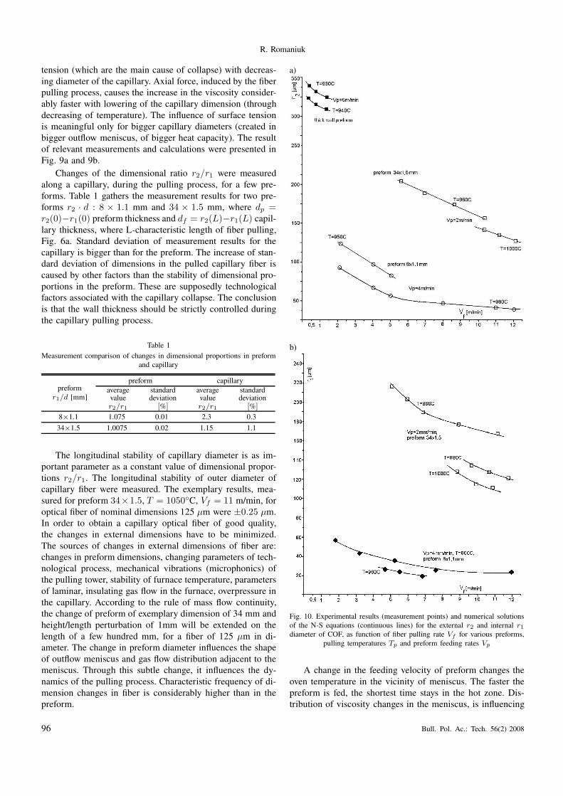
b)
Fig. 10. Experimental results (measurement points) and numerical solutions
of the N-S equations (continuous lines) for the external r2 and internal r1
diameter of COF, as function of fiber pulling rate Vf for various preforms,
pulling temperatures Tp and preform feeding rates Vp
A change in the feeding velocity of preform changes the
oven temperature in the vicinity of meniscus. The faster the
preform is fed, the shortest time stays in the hot zone. Dis-
tribution of viscosity changes in the meniscus, is influencing
96 Bull. Pol. Ac.: Tech. 56(2) 2008

Capillary optical fiber – design, fabrication, characterization and application
the collapse mechanisms. Preform feeding rate (aside of the
temperature) is one of the parameters for control of geomet-
rical proportions of the optical fiber capillary. It is, however,
not a very efficient parameter, because of big time constant of
this method of control (too big control loop latency). Dimen-
sion of the capillary hole depends strongly on the preform
feeding rate, thus this rate has to be stable. Fig. 9b presents
measured, relative dependencies of internal capillary diame-
ter on preform feeding rate. When the feeding is very slow,
the capillary is subject to collapse. In these conditions, small
changes in the preform feeding rate cause big changes in the
capillary diameter.
Figure 10 presents the measurement results and compari-
son with the numerical calculations for both capillary diam-
eters – internal and external. The data used for calculations
were: length of hot zone in the furnace, pulling parameters,
physical and chemical data of the glasses used for optical cap-
illary manufacturing. The higher furnace temperatures, lower
preform feeding rates, and bigger rates of optical fiber pulling,
all together lead to smaller dimensions of the capillary holes.
For bigger rates of the preform feeding, final dimensions of
the capillary are more sensitive to the pulling rate, than for
smaller rates of the preform feeding. For typically used puling
process parameters, the capillary collapse is quite weak. This
phenomenon is a strong function of the preform feeding rate.
In order to obtain a capillary optical fiber which images
the geometrical proportions of the preform, one has to obey
the following rules for technological parameters of the pulling
process: hot zone of the furnace should be the shortest (short-
ening of the outflow meniscus), process temperature should
be the lowest acceptable, preform feeding rate to the furnace
should be the highest acceptable, the preform and the capillary
optical fiber should have relatively big holes dimensions.
4. Characterization
The pulled capillary optical fibers were characterized optical-
ly and mechanically using standard measuring equipment for
classical fibers with modified signal coupling techniques. The
details of measurement set-ups are presented elsewhere [1].
Table 2 summarizes some of the parameters of available
COFs.
Table 2
Parameters of manufactured COF and DCCOF
Parameter, measure Kind, value
kind of glasses high silica, multicomponent: lime-calcium, lime-barium, lime-lead, borosilicates
refraction around 1.5 for high silica, typically 1.55–1.75 for compound, special higher refraction available on demand
fabrication complex crucible, extrusion, pulling from preform, hybrid-combined
geometrical dimensions [µm] a series of standardized types for internal capillary dimensions with 150µm of fiber outside dimension
or special dimensions on demand, especially of smaller diameters
external diameter standard dimensions in the range 30–350, special dimensions out of this range available on demand
– fiber [µm]
internal diameter standard dimensions 5–200, small dimensions capillary 1–5, special dimensions outside these ranges available
– capillary hole [µm]
on demand
stability of transverse dimensions standard dimensional stability better than 3 for the length sample of COF, special dimensional stability better
than 1% of COF [%]
average ellipticity [%] Standard ellipticity lower than 1 per sample length
protective jacketing Standard polyamide, hard, double-layered, on demand soft silicone,
internal thin film layer Non-protected or protected capillary hole after fiber fabrication, capillary surface conditioning
Conditioning materials Water, hydrogen, oxygen, inert gases, polymers, polyolefins, Teflon, tetra,
range of optical transparency [nm] Typically 400–2000, depending on COF material
Average level of transparency 90%/5 m in the visible range
refractive index profile Step-index, multi-step index
Internal numerical aperture Typically 0.05–0.3, bigger on demand
External numerical aperture 0.05–0.3, bigger on demand
Mechanical strength [GPa] 0.3–1.5
Weibull parameter 3–7
Average breaking radius of curvature Around 3–5 mm for 50 µm, around 15 mm for 200 µm
Length of provided COF samples A series of standardized dimensions, typically 20–40 cm, 1 m, 5 m, longer length samples on demand
for research and applications
Time of COF sample delivery 2 weeks for a fiber from a series of standardized types, 2 months for a fiber out of the series of standardized
types
Other fabricated specialty optical fibers ring-core, multi-ring core, elliptical core, of complex refractive index profile like M and W, noncircular core,
special material, sensitized and desensitized
Bull. Pol. Ac.: Tech. 56(2) 2008 97

R. Romaniuk
5. Applications
The availability of COFs has recently awakened locally the
interest in optical capillary based assemblies, modules and
MOEMS. A number of fabricated and characterized COF
samples, mainly in a series of standardized types, were made
available by the technological centers for application partners.
The fibers were primarily used for manufacturing of sensors
and microoptic functional devices. Prior to that the access to
more specialized and/or nonstandard COF and DCCOF fibers
was confined.
5.1. Microfluidics. A controlled flow of minute amounts of
fluids (liquids and gases alike) is a key to the construction of
laboratory on chip microsystems (LOC) [23]. Optically en-
hanced microfluidics embraces such devices, mainly planar
but also capillary, as transmission channels, semi-insulated
cavities, reactors, traps, windows, reactants inlets and out-
lets, optical inputs and outputs, optical or piezo pumps, split-
ters, couplers, etc. Optically enhanced microfluidics uses such
methods and processes like wave and matter transport, pump-
ing, mixing, heating or cooling, optical excitation, optical or
electro-optical measuring like pH-metry, spectroscopy, etc.
A series of experiments was performed on construction of
a COF based amplitude microoptic modules [24] with a mo-
bile microdroplet for the following applications in microflu-
idics, micro systems and optical microsensors: position sen-
sors via shift of a microdroplet in a capillary and CCD read-
out, frequency measurement of a microbeam resonance with
the center of gravity changes introduced by microdroplet shift,
pressure difference sensor between microcells in a microsys-
tem, optically controlled transport of matter in microsystems,
microdroplet microlens properties modulation, two phase –
gas and liquid – flow measurement, etc. A side advantage of
microfluidics systems is the possibility to make optical mea-
surements of manipulated fluid microsamples.
The measurement set up of a COF system with mobile
microdroplet was presented in Fig. 11. The microdroplet acts
as an optical microlens and as a movable mass. The basic op-
tical characteristics of this system were measured like signal
transmission and sensitivity to external reactions like thermal
and mechanical. Figure 11c presents two photos of the cross-
section of applied COF in the micromodule. The fiber is filled
with a series of spaced microdroplets. The photo shows pres-
ence of the ballistic modes for a short span of COF and core
modes for a longer span. This effect of switching between the
ballistic and core modes is obtained also as a result of beam
defocusing by the microlens and is effective irrespective to
the fiber length. The microlens is a strong filter for ballistic
modes. The measured characteristics show the performance
of the opto-mechanical-microsystem. The curve in Fig. 11d
shows changes in optical power transmission as a function of
microdroplet positioning in the capillary. For different liquid,
or for conditioned capillary surface, the lens may be convex.
Under the external influence the lens may change from convex
to concave and vice versa. The positioning may be done ther-
mally, electrically or mechanically (pressure). The character-
istic in Fig. 11e shows changes in optical power transmission
as a function of microlens refraction. The refraction may be
changed thermally or electrically, thus, the system is a kind of
MOEMS. The applied optical fiber capillaries are acting si-
multaneously in this experiment as classical capillaries. This
set up enables wide spectrum of optical measurements, in-
cluding longitudinal or transverse ones, and an active ener-
getic interaction of optical wave with microscopic amount of
transmitted material medium. Adding optics via COF tech-
nology to the microfluidics opens new areas in the MOEMS
technology.
a)
b)
c)
d)
e)
Fig. 11. (a) Measurement set-up and functional diagram of the microfluidicdevice, (b) ray tracing in capillary with microdroplets, (c) capillary fiber
end faces with ballistic and core modes, (d) measured characteristics of mi-
crooptic module with COF filled with liquid microdroplet lens, (e) changes
in optical power transmission as a function of microlens refraction. Fiber
data: multimode, df = 300 µm, dc = 260 µm, two fiber sample lengths
l1 = 50 mm, l2 = 300 mm. Microdroplet lens data: concave, volume 300 nl,
length on fiber axis L1 = 0.9 mm, L2 = 1÷ 200 mm. Measurements done
for λ = 670 nm (after Ref. 19)
98 Bull. Pol. Ac.: Tech. 56(2) 2008

Capillary optical fiber – design, fabrication, characterization and application
5.2. Micro-refractometry. Optical refractometers or spec-
troscopes based on capillary optical fibers confine the mea-
sured media to the capillary core and increase the sample
interaction lengths, thus enhancing the intensity of spectro-
scopic image. Capillary made of glass, even low-index one is
capable of transmitting light by total internal reflection only
for high-index liquids. Capillary made of amorphous fluo-
ropolymer (Teflon), having a refractive index of 1,29 is capa-
ble of supporting optical wave transmission virtually for any
liquid, including aqueous, alcohol and light aromatic hydro-
carbons solutions. Thus, some of the COF refractometers for
low index liquids have to be fabricated of low-loss transparent
Teflon, instead of glass.
a) b)
c)
d)
e)
Fig. 12. (a) Measuring set-up for calibration of a COF microrefractometer, A – container with normalized glucose solution or alternatively with a measuredliquid, B – stabilized power supply, C – He-Ne laser, D – optical power meter, E – detector, F – multimode optical fiber for power delivery, G – capillary
optical fiber, H – sink for flowing liquid; (b) Construction of the optical coupling between COF and a classical transmitting and receiving fibers; (c) Measured
calibration characteristic of the COF based microrefractometer, electrical output E as a function of liquid refraction. COF is filled with glucose solution;
(d) Measurement characteristic of a COF refractometer used for in-flow oil thermometry; (e) a photo of a COF set-up used for the construction of the
microrefractometer in longitudinal and transverse views after Ref. 20. E[r.u.] is a signal on the detector in relative units. Fiber data: outside diameter 1300 µm,
outside diameter of optical core 1100 µm, capillary hole diameter 800 µm, n1 = 1.524 n2 = 1.510 after Refs. 20, 21. T = 20◦C
Bull. Pol. Ac.: Tech. 56(2) 2008 99

R. Romaniuk
A number of amplitude and phase COF based microop-
tic modules were constructed for refractometry, colorimetry,
opacimetry and optical thermometry. Some of them also base
on the microfluidics solutions. There were measured refrac-
tions of the muster solutions of glucose for the COF sensor
calibration. Configuration of the measuring set-up, construc-
tion of the COF-classical fiber coupler, calibration curve and
refractometer photo were presented in Fig. 12. Figure 12e
shows a close up view of the capillary cross section and fiber
refractometer transmitting HeNe laser radiation coupled from
and back to a multimode telecom grade fiber from above.
The telecom fibers are connected to the light source and to
the detector.
The calibration curve of COF microrefractometer,
Fig. 12c is based on the dependence of molar refraction of
two component solution: R12 = x1R1 + x2R2 = [(n2− 1)
(x1M1 + x2M2)]/ρ12(n2 + 2). The refraction is n12 =
sqrt[3R12ρ12/(M12 − R12ρ12) + 1], where n12 is the refrac-
tion of the mixture, ρ12 is density, R12 is molar reactivity,
M12 molar mass of the mixture. The accuracy or refraction
measurements is ±10−3. The constructed COF microrefrac-
tometer is used for determination of unknown refraction of
fluids. It is used as a continuous flow sensor in chemical pro-
cesses.
5.3. Flow micro-thermometry. The same principle, as pre-
sented in Fig. 12a was used for the construction of a capillary
flow microthermometer [21] The capillary was positioned on
a Peltier cell and a heater. As above, its predicted applications
is in MOEMS as well as in electrically insulated systems. The
temperature of oils was measured via the known changes of
their refractive index n(T ) [25], Fig. 12d. The increase in
temperature causes a different decrease of refraction specific
to particular kind of oil. In-flow oil recognition sensor is based
on this principle. The relevant dependence, binding the refrac-
tive index n with material density ρ and temperature T , is the
Lorentz-Lorenz formula: (n2−1)/(n2+2)ρ = 4π?(1−F )/3,
where ? is average polarizability, F is molecular correction
factor expressed as expansion series of ?. A two phase flow
was observed in some oils above 150◦C, which was a sign of
oil degassing.
5.4. Gas sensors. Capillary optical fiber gas sensors use im-
mobilized indicators lining with a thin layer the surface of
a capillary hole [23]. The immobilizing agents depend on the
active substance of the indicator. They are for example: am-
monium (or other chemically binding substance) as a chemical
bond and cellulose matrix or hybrid xerogels as mechanical
fixture. The xerogels are composed of alkyl and perfluoroalkyl
ORMOSILs (organically modified silicates). The xerogels dis-
play good adhesion to the glass surface and are prone to dop-
ing with a range of different indicators. The indicators depend
on the gas to be detected. In case of CO2, the indicators are
HPTS, PTS, TOA, TOAOH.
The mechanism of gas detection is based either on pH
changes or on fluorescence intensity modulation of the indi-
cator. The gas dissolves in the sensing layer, which is bonded
directly to the internal glass fiber surface either changing the
system pH or quenching the fluorescence. The sensing cham-
ber of long length but small volume provides short reaction
time, usually of the order of tens of s. The quality of the sensor
depends on the technology of the dyes which are immobilized
in polymer and on polymer membranes. The measuring range
of sensor is determined by particular application. In the case
of methane these are safety regulations or for CO2 this is
the range of water dissolution for this gas, i.e 1–20 hPa. The
accuracy of measurement in the latter case should be better
than 1 hPa. The calibration of COF gas sensor is done by
exchanging the measured gas atmosphere with the inert gas
like helium or nitrogen and measuring the reaction time or
presence of the process hysteresis. Usually the reaction time
from inert gas to the measured medium is very fast but in the
reverse it is an order of magnitude longer. This is associated
with washing out of the measuring substance and saturation
processes in the indicator. The experiments with usage of cel-
lulose matrix and hybrid xerogels doped with HPTS in COF
gas sensors show the increased response, sensitivity, measur-
ing range and speed of these devices.
5.5. Micro-optics. Several microoptic and micro-opto-
mechanical components based on the fabricated COFs were
developed at our and partner laboratories. These are basic
devices necessary for laboratory work with advanced fiber
optic systems and MOEMS. They embrace: permanent and
reusable connectors between classical fibers and COFs, COF
T and Y splitters with capillary hole continuity, alignment mi-
crodevices for COFs and classical fibers, COF tapers, single-
mode and multimode COF patch cords, standardized dimen-
sionally precision optical tubing, COF connectors to pla-
nar microsystems with buried optical waveguides and matter
channels, etc.
The dimensional compatibility decides frequently of the
direct and easy application of COF in existing microsystems.
It concerns mainly fitting with classical optical fibers. COFs
of standardized external dimensions equal to 125 µm and
150 µm were used together with classical optical fibers for
construction of micro Fabry-Perot resonators, for modal fil-
ters, etc. Such fibers are also used for building the Y and Tsplitters. COFs of standardized internal dimensions equal to
125 µm+1 µm and 150 µm+1 µm were used as the precise
mechanical tubing with optical alignment insight and for oth-
er related purposes. COF dimensions used for the microoptics
are gathered in Table 3.
Other parameter, apart from the dimensions, deciding of
practical applications of COF is maintaining the continuity
of the capillary in combined branched microsystems support-
ing the transmission of wave and matter. One of the basic
solution to this is to use standardized open channel connec-
tors, adapted from the classical chemical capillary techniques
and modified to optical purposes to enable low-loss optical
connectivity.
100 Bull. Pol. Ac.: Tech. 56(2) 2008

Capillary optical fiber – design, fabrication, characterization and application
Table 3
Dimensional specifications of COFs for fabricated microoptic applications
application field /
dimensions [µm]
optical aligning
components
micromechanical
coupling
microbeams
for MOEMS
micromechanical
switches
chemical
sensors
optical
sensors
hole diameter
[µm]125–127,
150–15250 50, 100 125 200 200, 300
outside diam.
[µm]150, 200 125 100, 125, 150 150, 200 300 300, 500
6. Conclusions
Capillary optical fibers are used more and more frequently
in practical applications like sensors but still not as frequent-
ly as classical fibers and classical capillaries. It stems from
very strong economic domination of classical chemical capil-
lary technologies with the global market of hundreds M$ and
from the conservative approach of chemical industries. The
simplest way to broad applications in this area is to replace
classical capillaries with their optically enhanced analogies.
They immediately provide active optical interaction with the
transported chemical medium. They require, however, a sup-
plement of optical infrastructure like transmitters, receivers
and analyzers attached to classical capillary paths.
Together with the development of COF technique a new
terminology was introduced. The COFs are also known as
optical fibers with a macro-hole, as differentiated of the ones
with micro-holes. Both types of fibers are named together as
hollow or holey – the latter name is reserved for photonic
fibers. Optical fibers with an internal discrete hole are of the
following kinds: the core as a hole, a hole close to the core,
the core around a hole and the core suspended in air or the
core in the hole. A beginning to these technologies stems from
chemical capillaries turned to liquid filled core optical fibers.
Potential applications of COFs are broad and stem from
the following factors and effects: transmission of large opti-
cal power in air core, large influence of the hole on optical
core, filling the core with a measured medium, large inter-
action length between the medium filling the core and the
evanescent or guided wave, guidance of various waves like
surface WGM, modulation of surface tension in liquids fill-
ing the capillary, usage of different guidance mechanisms –
refractive and diffractive-interference.
Recent developments in COF applications are associ-
ated with optical wave transmission using Von Neumann-
Wigner mechanism and coherent transmission of singlemode
deBroglie wave inside a dark light beam. The latter is associ-
ated with strictly ordered transmission of single cold atoms.
COF nanometer tapers are used as tips for optical version of
an atomic force microscope (AFM). The investigated surface
is probed with single helium atoms emanating from the COF
tip. Other atoms are deposited in single quantities on a sur-
face (active inversed lithography) in an ordered way by such
a probe.
The COFs have different properties, and thus application
perspectives, as classical optical fibers. The fundamental fea-
ture is close proximity between an external interaction and the
optical guided field. This proximity makes the COF based de-
vice very sensitive. The best example of this kind of sensibil-
ity is an integrated COF spectrometer with evanescent wave,
with the measured medium filling the hole. Such a spectrom-
eter makes a part of a microsystem.
The research on COF application use frequently the fil-
aments of standard dimensions like 125 µm and 150 µm. It
stems from the availability of measuring equipment for the
telecom fiber geometry standards. The most frequently used
internal diameter of capillary is a few µm for singlemode
and a few tens µm for multimode COFs. The following prac-
tical devices were constructed of COFs and side-hole opti-
cal fibers: integrated temperature and strain sensors, polariz-
ers, elastooptic components, chemical sensors, amplitude and
phase sensors, spectrometers, optrodes and components for
microsystems.
The availability of COF samples, as a result of realization
of the program PBZ Optoelectronic Modules, supplements the
existing offer of tailored optical fibers delivered previously for
the research purposes as a result of realization of the program
PPPW Photonics Engineering. The availability of COFs has
clearly activated the interest in research on such micro-system
technologies as MOEMS and LOC. The basic parameters of
COFs for the users, relevant to the applications under devel-
opment, turned out to be: kind of glass, refraction, geometry
– external dimensions and internal proportions between hole
and optical core. The COF material determines the sensiti-
zation method to a particular external reaction the fiber is
subject to. The COF refraction determines the kind of refrac-
tive environment the fiber is used in. The COF geometrical
proportions determines fiber usage as an amplitude or phase
sensor.
Acknowledgements. The work on capillary optical fibers was
supported by the Research Program on “Optoelectronic Com-
ponents and Modules for Applications in Medicine, Indus-
try, Environment Protection and Military Technology”, PBZ-
MIN-009/T11/2003 (2004–2007).
The author acknowledges cooperation with prof. J. Dorosz
and his co-workers of Białystok University of Technology on
fabrication, characterization and application of capillary opti-
cal fibers.
The author acknowledges cooperation with prof.
W. Woliński of Warsaw University. of Technology, chair of
the Research Program on Photonics Engineering (1995–2001)
and selected part of Research Program on Optoelectronic
Components and Modules (2004–2007).
Bull. Pol. Ac.: Tech. 56(2) 2008 101

R. Romaniuk
REFERENCES
[1] R. Romaniuk and J. Dorosz, Design and Fabrication of Cap-
illary Optical Fibers, Technical Report, Grant PBZ-MIN-
009/T11/2003 (2003–2007), Warsaw University of Technology,
2007, (in Polish).
[2] A.B. Sotsky and L.I. Sotskaya, “Modes of capillary optical
fibers”, Optics Communications 230 (1–3), 67–79 (2003).
[3] M.A. Olshanii, Yu.B. Ovchinnikov, and V.S. Letokhov, “Laser
guiding of atoms in a hollow optical fiber”, Opt. Commun 98,
77–80 (1993).
[4] J.F. Giuliani, Optical Fiber Sensor for Methane Gas, US Patent
4708941, 1987.
[5] R. Altcorn, I. Koev, R.P. VanDuyne, and M. Litorja, “Low-
loss liquid-core optical fiber for low-refractive-index liquids:
fabrication, characterization, and application in Raman spec-
troscopy”, Applied Optics 36 (34), 8992–8998 (1997).
[6] J. Bravo, I.R. Matias, I.D. Villar, J.M. Corres, and F.J. Arregui,
“Nanofilms on hollow core fiber-based structures: an optical
study”, J. Lightwave Technol. 24 (5), 2100–2105 (2006).
[7] K. Matsumura, Y. Matsumura, and J.A. Harrington, “Evalua-
tion of gold, silver and dielectric coated hollow glass waveg-
uides”, Opt. Eng. 35, 3418–3421 (1996).
[8] V. Neves and A.S.C. Fernandes, “Modal characteristics of A-
type and V-type dielectric profile fibres”, Microwave and Op-
tics Technology Letters 16(3), 164–169 (1998).
[9] R. Romaniuk and J. Dorosz, “Technology of soft-glass optical
fiber capillaries”, Proc. SPIE 6347, 634711-634718 (2006).
[10] E.A.J. Marcatili and R.A. Schmetzer, “Hollow metallic and
dielectric waveguides for long distance optical transmission”,
Bell Syst. Tech. J. 43, 1783 (1964).
[11] D.H. Bilderback, “Review of capillary x-ray optics from the
2nd International Capillary Optics Meeting”, X-Ray Spectrom-
etry 32, 195–207 (2003).
[12] P. Glas, M. Nauman, A. Schirrmacher, and T. Pertsch,
“Neodymium-doped hollow optical fiber laser for applications
in laser-guided atoms”, Proc. CLEO 60, 428–429 (1998).
[13] P. Polynkin, A. Polynkin, N. Peyghambarian, and M.
Mansuripur, “Evanescent field-based optical fiber sensing de-
vice for measuring the refractive index of liquids in microflu-
idic channels”, Opt. Lett. 30, 1273–1275 (2005).
[14] P.J.A. Sazio, A. Amezcua-Correa, C.E. Finlayson, J.R. Hayes,
T.J. Scheidemantel, N.F. Baril, B.R. Jackson, D.J. Won,
F. Zhang, E.R. Margine, V. Gopalan, V.H. Crespi, and J.V.
Badding, “Microstructured optical fibers as high-pressure mi-
crofluidic reactors”, Science 311, 1583–1586 (2006).
[15] J. Mrazek, V. Matejec, M. Hayer, J. Skokankova, I. Kasik,
D. Berkova, and F. Kostka, “Capillary optical fibers modified
by xerogel layers for chemical detection“, Proc. SPIE 6180,
618013.1–6 (2006)
[16] Department of Optical Fiber Technology, Maria Curie-
Skłodowska University,
http://www.umcs.lublin.pl/jednostki.php?id=323.
[17] Department of Optical Radiation, Białystok University of Tech-
nology, http://vela.pb.bialystok.pl/∼kpo/.
[18] PBZ-MIN-009/T11/2003, “Optoelectronic components and
modules for applications in medicine, industry, environment
protection and military technology”, Ministry of Science and
Informatization,
http://kbn.icm.edu.pl/finauki98/PBZ/lista projektow 20031020.
html, 2003.
[19] M. Borecki, M.J. Korwin-Pawłowski, M. Bebłowska, “Light
transmission characteristics of silica capillaries”, Proc. SPIE
6347, 634741–634747 (2006).
[20] P. Miluski and D. Dorosz, “Measurement of refractive index
using capillary waveguide”, Proc. SPIE 6347, 634742–634746
(2006).
[21] P. Miluski, “The temperature sensor based on capillary waveg-
uide”, Proc. SPIE 6937, 693755–683759 (2007).
[22] M. Gregory Forest and Hong Zhou, “Unsteady analyses of
thermal glass fibre drawing process”, Europ. J. Applie Mathe-
matics 12, 479–496 (2001).
[23] A. Dybko, Warsaw Univ. Technology, Faculty of Chemistry,
Department of Chemical Sensors, private communications.
[24] M. Borecki, Warsaw Univ. Technology, Institute of Micro and
Optoelectronics, Department of Microsystems Technology, pri-
vate communications.
[25] S.A. Khodier, “Refractive index of standard oils as a function
of wavelength and temperature”, Optics and Laser Technology
34, 125–128 (2002).
102 Bull. Pol. Ac.: Tech. 56(2) 2008