
lunyax.files.wordpress.comcapacity factor, use factor, diversity factor, dema nd factor, Effect of...
59
Power Plant Engineering 7/1/2016 VTU Notes By Kiran Vijay Kumar
Transcript of lunyax.files.wordpress.comcapacity factor, use factor, diversity factor, dema nd factor, Effect of...

Power Plant
Engineering
7/1/2016
VTU Notes
By Kiran Vijay Kumar

Syllabus
Part – A UNIT – 1 Steam Power Plant: Different types of fuels used for steam generation, Equipment for burning coal in lump form, strokers, different types, Oil burners, Advantages and Disadvantages of using pulverised fuel, Equipment for preparation and burning of pulverised coal, unit system and bin system. Pulverised fuel furnaces, cyclone furnace. UNIT – 2 Coal, Ash Handling and Different Types of Boilers: Coal and Ash handling, Generation of steam using forced circulation, high and supercritical pressures, A brief account of LaMount, Benson, Velox, Schmidt, Loeffer and Ramson steam generators. UNIT – 3 Chimneys, Accessories for the Steam Generator Cooling Towers and Ponds: Natural, forced, induced and balanced draft, Calculations involving height of chimney to produce a given draft. Accessories for the Steam Generator such as super-heaters, desuperheater, control of super heaters, Economisers, Air Pre-heaters Study of different types of cooling towers and ponds. UNIT – 4 Diesel Engines and Gas Turbine Power Plant: Method of starting diesel engines, Cooling and lubrication system for the diesel engine. Filters, centrifuges, Oil heaters, Intake and exhaust system, Layout of a diesel power plant. Advantages and disadvantages of the gas turbine plant, Open and closed cycle turbine plants with the accessories. Part – B UNIT – 5 Hydro-Electric Plants: Storage and pondage, flow duration and mass curves, hydrographs, Low, medium and high head plants, pumped storage plants, Penstock, water hammer, surge tanks, gates and valves, power house, general layout. A brief description of some of the important Hydel Installations in India. UNIT – 6 Nuclear Power Plant: Principles of release of nuclear energy Fusion and fission reactions. Nuclear fuels used in the reactors. Multiplication and thermal utilization factors. Elements of the Nuclear reactor, Moderator, control rod, fuel rods, coolants. Brief description of reactors of the following types - Pressurized water reactor, Boiling water reactor, Sodium graphite reactor, Homogeneous graphite reactor and gas cooled reactor, Radiation hazards, Radio active waste disposal. UNIT – 7 Choice of site: for power station, load estimation, load duration curve, load factor, capacity factor, use factor, diversity factor, demand factor, Effect of variable load on power plant, selection of the number and size of units. UNIT – 8 Economic Analysis of power plant: Cost of energy production, selection of plant and generating equipment, performance and operating characteristics of power plants, tariffs for electrical energy.

CONTENTS Page
Unit 2: Coal, Ash Handling and Different Types of Boilers 1. Coal handling 1 2. Ash handling 3 3. High pressure boilers 4 4. Generation of steam using forced circulation, high and supercritical pressure 9
Unit 3: Chimneys, Accessories for the Steam Generator Cooling Towers and Ponds
5. Chimney 12 6. Draught system 12 7. Types of Draught systems 12
8. Boiler Accessories 16 9. Cooling Tower 20 10. Pondage 24
Unit 4: Diesel Engine and Gas Turbine Power Plant 11. Application of diesel engine electric plant 25 12. Layout of a diesel power plant 25 13. Starting of engine 26 14. Essential component or element of diesel electric plant 26
15. Introduction to Gas Turbine (GT) Power Plant 32 16. Open cycle gas turbine power plant 33 17. Closed cycle gas turbine power plant 33 18. Essential component of GT power plant 34
Unit 5: Hydro Electric Plant 19. General layout of Hydel power plant 36 20. Classification of Hydel Plants 39 21. Storage & Pondage 42 22. Hydrograph 43 23. Flow Duration Curve 43 24. Mass Curve 44 25. Gates and valves 44 26. Hydraulic installation in India 45
Unit 6: Nuclear Power Plant 27. General Structure of Nuclear power plant 46 28. Nuclear Energy 48 29. Multiplication Factor & Thermal Utilization Factor 49 30. Classification of reactor 50 31. Pressurized Water Reactor 50 32. Boiling Water Reactor 51 33. Liquid metal Fast Breeder Reactor 52 34. Gas Cooled Reactor 53 35. Effects of Nuclear Radiation 54 36. Radioactive Waste Disposal Systems 54 37. Nuclear fuel 55 REFERENCE

Power Plant Engineering
Kiran Vijay Kumar
Coal, Ash Handling and Different Types of Boilers
Syllabus:- Coal, Ash Handling and Different Types of Boilers
using forced circulation, high and supercritical pressures, A brief account of LaMount, Loeffer and Ramson steam generators.
Coal handling:- Coal handling is done as shown in fig bellow.
Following stages or steps involved in coal handling
1. Coal delivery 4. Transfer 7. Weighing and measuring
1. Coal delivery: coal is supplied from point of delivery to power station. Coal is supplied by ship
or boat if power station is situated near sea or river and situated away from sea or river.
2. Unloading: Unloading coal at power station depends on how coal is received at power station. If
coal is delivered by truck there is no need of unloading devices. If coal is delivered or boat unloading is done by car shakes, rotary car dumpers, crane, grab bucket, coal accelerator etc.
Power Plant Engineering
Unit - 2
Coal, Ash Handling and Different Types of Boilers
Coal, Ash Handling and Different Types of Boilers : Coal and Ash handling, Generation of steam using forced circulation, high and supercritical pressures, A brief account of LaMount, Benson, Velox, Schmidt, Loeffer and Ramson steam generators.
Coal handling is done as shown in fig bellow.
Following stages or steps involved in coal handling 2. Unloading 3. Preparation 5. Coal Storage 6. In plant handling
Weighing and measuring 8. Furnace firing
coal is supplied from point of delivery to power station. Coal is supplied by ship or boat if power station is situated near sea or river and by truck or train if power station is situated away from sea or river.
Unloading coal at power station depends on how coal is received at power station. If coal is delivered by truck there is no need of unloading devices. If coal is delivered or boat unloading is done by car shakes, rotary car dumpers, crane, grab bucket, coal accelerator
Coal delivery
Unloading
Preparation
Transfer
Outdoor storage
Covered Storage
In-plant handling
Weighing and measuring
Furnace firing
Page 1
Coal, Ash Handling and Different Types of Boilers
: Coal and Ash handling, Generation of steam Benson, Velox, Schmidt,
Preparation In plant handling Furnace firing
coal is supplied from point of delivery to power station. Coal is supplied by ship by truck or train if power station is
Unloading coal at power station depends on how coal is received at power station. If coal is delivered by truck there is no need of unloading devices. If coal is delivered by train, ship or boat unloading is done by car shakes, rotary car dumpers, crane, grab bucket, coal accelerator

Power Plant Engineering
Kiran Vijay Kumar Page 2
3. Preparation: When the coal is delivered in the big form of lumps and it is of not proper size, the preparation (sizing) of coal is achieved by using crushers, breaker and magnetic separator.
4. Transfer: after preparation coal is transferred to the dead storage by any of following method,
i. Belt conveyer ii. Screw conveyer iii. Bucket elevator iv. Grab bucket elevator v. Skip hoist vi. Flight conveyer
5. Coal storage: It desirable to store sufficient quantity of coal to protect against interruption of
coal supplies. The amount of coal supply depends upon availability of free space, transportation facility and nearness of power station to the coal mine.
Usually coal required per month of operation is stored in the plant in case if the power station is long way from coal supply. Coal required for 15 days is stored when coal supply is near. Storage of coal for long period is not advised since it blocks the capital and deterioration of coal quality.
The coal received at power station is stored in outdoor storage (Dead storage) in the form of piles laid directly on the ground.
6. In plant handling: From the outdoor storage the coal is brought to the cover storage (live storage) like bins or bunkers. In plant handling includes equipment such as belt conveyer, screw conveyer, bucket elevator etc. to transfer the coal. Weigh Lorries, hoppers and automatic scales are used to record the quantity of coal delivered to the furnace.
7. Weighing and measuring: Weigh Lorries, hoppers and automatic scales are used to weigh quantity of coal. The commonly used method of weighing coal is as follows:
i. Mechanical ii. Pneumatic iii. Electronic Mechanical method works on lever system mounted on knife edge and bearing
connected to resistance in the form of spring of pendulum. Pneumatic weighers use pneumatic transmitted weigh heads and corresponding air pressure to determine load applied. The electronic weighing machine makes use of load cells which produces voltage proportional to the load applied.
8. Furnace firing: Finally, a correct weighed amount of coal is burnt in the furnace to convert water into steam.
Coal handling system:- Mechanical handling of coal is preferred over manual handling due to the following reasons:
1. High reliability. 2. Less labor required. 3. Economical for medium and large plants. 4. Operation is easy and smooth. 5. Can be easily started. 6. Minimum labor is put to unhealthy condition. 7. Loss in transport is minimized.
Disadvantages: 1. Needs continuous maintenance and repair. 2. Capital cost of plant is high. 3. In mechanical handling some power generated is usually consumed resulting less power available
to consumers.

Power Plant Engineering
Kiran Vijay Kumar
Ash handling:-
� The above figure shows layout of ash handling and dust collection system A huge quantity of ash is produced in central station, sometimes 10 to 20% of total coal burnt a day. Hundreds of tons of ash may be burnt a day in a power station. A station using low grade fuel may have to deal with large quantity of ash. Ash handling includes:
(i) Ash removal from furnace.(ii) Loading on conveyers and delivery to disposal in sales or dumping.
Ash handling is a problem because ash coming from furnace is too hot, dusty, irritating to
handle and accompanied by some poisonous gas. Ash needs to befollowing reason:
(i) Reduce corrosive action of ash.(ii) Reduce dust in ash. (iii) Reduce temperature of ash.(iv) Clinkers can be reduced (clinkers are formed when ash fused with large lumps).
Ash handling equipment:-
The mechanical means perform following functions.
(1) Capital investment, operating and maintenance charges of equipment should be low.(2) It should be able to handle large quantity of ash.(3) Clinker, soot, dust etc. creat
smoothly. (4) The equipment used should remove ash from furnace, load it to conveyers and deliver to
dumping site or storage and finally disposal.(5) The equipment should be corrosion and wear resistance.
The commonly used ash handling equipments are,
(i) Bucket elevator. (ii) Bucket conveyer. (iii) Belt conveyer. (iv) Pneumatic conveyer. (v) Hydraulic sluicing equipment.(vi) Trollies or rail cars etc.
Power Plant Engineering
The above figure shows layout of ash handling and dust collection systemA huge quantity of ash is produced in central station, sometimes 10 to 20% of total coal burnt
a day. Hundreds of tons of ash may be burnt a day in a power station. A station using low grade fuel may have to deal with large quantity of ash.
Ash removal from furnace. Loading on conveyers and delivery to disposal in sales or dumping.
Ash handling is a problem because ash coming from furnace is too hot, dusty, irritating to handle and accompanied by some poisonous gas. Ash needs to be quenched before handling due to
Reduce corrosive action of ash.
Reduce temperature of ash. Clinkers can be reduced (clinkers are formed when ash fused with large lumps).
The mechanical means are required for disposal of ash. The handling equipment should
Capital investment, operating and maintenance charges of equipment should be low.It should be able to handle large quantity of ash. Clinker, soot, dust etc. create troubles; the equipment should be able to handle them
The equipment used should remove ash from furnace, load it to conveyers and deliver to dumping site or storage and finally disposal. The equipment should be corrosion and wear resistance.
The commonly used ash handling equipments are,
Hydraulic sluicing equipment.
Page 3
The above figure shows layout of ash handling and dust collection system
A huge quantity of ash is produced in central station, sometimes 10 to 20% of total coal burnt a day. Hundreds of tons of ash may be burnt a day in a power station. A station using low grade fuel
Ash handling is a problem because ash coming from furnace is too hot, dusty, irritating to quenched before handling due to
Clinkers can be reduced (clinkers are formed when ash fused with large lumps).
are required for disposal of ash. The handling equipment should
Capital investment, operating and maintenance charges of equipment should be low.
e troubles; the equipment should be able to handle them
The equipment used should remove ash from furnace, load it to conveyers and deliver to

Power Plant Engineering
Kiran Vijay Kumar
Ash handling system:- The modern ash handling systems classified into four groups:
1. Mechanical handling system2. Hydraulic system. 3. Pneumatic system. 4. Steam jet system
High pressure boilers:- In all the modern power plants, high pressure boilers (>100bar) are universally used as
have following advantages. 1. Efficiency and Capacity of plant is increased if high pressure steam is used.2. Forced circulation provides freedom in arrangement of furnace and walls, hence reduces heat
exchange area. 3. Tendency of scale formation is 4. Danger of overheating is reduced as all parts are uniformly heated.5. Differential expansion is reduced due to uniform temperature, hence reducing gas and air
leakage. Type of high pressure supper critical boiler,
1. La mount boiler 2. Benson boiler 3. Loeffler boiler 4. Velox boiler 5. Schmidt Hartmann boiler6. Ramson boiler
1. La Mont Boiler :-
Power Plant Engineering
The modern ash handling systems classified into four groups: Mechanical handling system
In all the modern power plants, high pressure boilers (>100bar) are universally used as
Efficiency and Capacity of plant is increased if high pressure steam is used. Forced circulation provides freedom in arrangement of furnace and walls, hence reduces heat
Tendency of scale formation is reduced due to high velocity water. Danger of overheating is reduced as all parts are uniformly heated. Differential expansion is reduced due to uniform temperature, hence reducing gas and air
Type of high pressure supper critical boiler,
Schmidt Hartmann boiler
Page 4
In all the modern power plants, high pressure boilers (>100bar) are universally used as they
Forced circulation provides freedom in arrangement of furnace and walls, hence reduces heat
Differential expansion is reduced due to uniform temperature, hence reducing gas and air

Power Plant Engineering
Kiran Vijay Kumar
A forced circulation boiler was first introduced by La Mount in 1925. The arrangement of water circulation and different component is as • The feed water from hot well is supplied to a steam and water drum through the economizer.• Most of the sensible is supplied to feed water while passing through economizer.• A pump is used to circulate the water through the evaporator tube a
into water drum. • Pump delivers water to header above drum pressure.• Distribution header distributes water through nozzle into the evaporator.• The steam separated in boiler is further passed through supper
superheated steam at pressure 120bar and temperature 500 2. Benson Boiler:-
Operations or working: • During the starting of engine, the water from feed pump is fed into the economizer where the
water is preheated. • The preheated water from
to steam by passing through heated tubes.• The vapor from evaporator is passed through section or small tubes to attain maximum
velocity • Then it is passed through supper heater to supper heat • The supper heated, high velocity then moved to the prime mover which is used to generate
power.
Merits of Benson Boiler 1) The total boiler cost and weight is less as there is no steam drum. 2) A Benson boiler occupies lesser space area. 3) All the joints in Benson boiler are welded and because of lesser number of components the
erection is faster.
Power Plant Engineering
A forced circulation boiler was first introduced by La Mount in 1925. The arrangement of water circulation and different component is as shown in figure.
The feed water from hot well is supplied to a steam and water drum through the economizer.Most of the sensible is supplied to feed water while passing through economizer.A pump is used to circulate the water through the evaporator tube and part of vapor is separated
Pump delivers water to header above drum pressure. Distribution header distributes water through nozzle into the evaporator. The steam separated in boiler is further passed through supper-heater to generate 45superheated steam at pressure 120bar and temperature 5000C
During the starting of engine, the water from feed pump is fed into the economizer where the
The preheated water from economizer is passed through evaporator where water is converted to steam by passing through heated tubes. The vapor from evaporator is passed through section or small tubes to attain maximum
Then it is passed through supper heater to supper heat the steam. The supper heated, high velocity then moved to the prime mover which is used to generate
The total boiler cost and weight is less as there is no steam drum. A Benson boiler occupies lesser space area. All the joints in Benson boiler are welded and because of lesser number of components the
Page 5
A forced circulation boiler was first introduced by La Mount in 1925. The arrangement of water
The feed water from hot well is supplied to a steam and water drum through the economizer. Most of the sensible is supplied to feed water while passing through economizer.
nd part of vapor is separated
heater to generate 45 to 50ton
During the starting of engine, the water from feed pump is fed into the economizer where the
economizer is passed through evaporator where water is converted
The vapor from evaporator is passed through section or small tubes to attain maximum
The supper heated, high velocity then moved to the prime mover which is used to generate
All the joints in Benson boiler are welded and because of lesser number of components the

Power Plant Engineering
Kiran Vijay Kumar
4) As this boiler works at a high pressure of 250when sudden fall of demand occurs.
5) Possibility of explosion does not rise as there is no boiler drum. 6) Benson boiler can be started very quickly from cold.
Demerits of Benson Boiler1) It has low steam, capacity and hence not suitable for high power outputs. 2) There are possibilities of overheating of econ
water pump problems in running conditions.3) It cannot meet sudden, raise, in demand.
3. Loeffler Boiler :-
The major difficulty experienced in Benson Boiler is the deposition of salt and sediment on the inner surfaces of the water tubes. The deposition reduced the heat transfer and ultimately the generating capacity. This further increased the danger of overheacid has high thermal resistance.
The difficulty was solved in Loeffler boiler by preventing the flow of water into the boiler tubes. Most of the steam is generated outside from the feed water using part of the supercoming out from the boiler.
• The pressure feed pump draws the water through the economizer and delivers it into the
evaporator drum as shown in the figure. • The steam circulating pump draws the saturated steam from the evaporator drum and is
through the radiant super heater and then connective super heater. • About 35% of the steam coming out from the super heater is supplied to the High Pressure steam
turbine and 65% of the steam coming out of super heater is passed through the evapororder to evaporate the feed water a coming from economiser.
• The steam coming out from high pressure turbine is passed through re heater before supplying to low pressure turbine.
Power Plant Engineering
works at a high pressure of 250bars there is no danger of bubble formation even when sudden fall of demand occurs.
explosion does not rise as there is no boiler drum. Benson boiler can be started very quickly from cold.
Demerits of Benson Boiler It has low steam, capacity and hence not suitable for high power outputs. There are possibilities of overheating of economizer, evaporator and super heater, in cases of feed water pump problems in running conditions. It cannot meet sudden, raise, in demand.
The major difficulty experienced in Benson Boiler is the deposition of salt and sediment on the inner surfaces of the water tubes. The deposition reduced the heat transfer and ultimately the generating capacity. This further increased the danger of overheating the tubes due to salt deposition acid has high thermal resistance.
The difficulty was solved in Loeffler boiler by preventing the flow of water into the boiler tubes. Most of the steam is generated outside from the feed water using part of the super
The pressure feed pump draws the water through the economizer and delivers it into the evaporator drum as shown in the figure. The steam circulating pump draws the saturated steam from the evaporator drum and isthrough the radiant super heater and then connective super heater. About 35% of the steam coming out from the super heater is supplied to the High Pressure steam turbine and 65% of the steam coming out of super heater is passed through the evapororder to evaporate the feed water a coming from economiser. The steam coming out from high pressure turbine is passed through re heater before supplying to
Page 6
bars there is no danger of bubble formation even
omizer, evaporator and super heater, in cases of feed
The major difficulty experienced in Benson Boiler is the deposition of salt and sediment on
the inner surfaces of the water tubes. The deposition reduced the heat transfer and ultimately the ating the tubes due to salt deposition
The difficulty was solved in Loeffler boiler by preventing the flow of water into the boiler tubes. Most of the steam is generated outside from the feed water using part of the superheated steam
The pressure feed pump draws the water through the economizer and delivers it into the
The steam circulating pump draws the saturated steam from the evaporator drum and is passed
About 35% of the steam coming out from the super heater is supplied to the High Pressure steam turbine and 65% of the steam coming out of super heater is passed through the evaporator drum in
The steam coming out from high pressure turbine is passed through re heater before supplying to

Power Plant Engineering
Kiran Vijay Kumar
This boiler can carry higher salt concentration than any otherindirectly heated boilers having natural circulation. These qualities fit it for land or sea transport power generation. Loeffler boilers with generating capacity of 94.5tonnes/hr and operating at 140bar have already been commissioned.
4. Velox Boiler:-
Operations: • This boiler design makes use of pressurized combustion, to achieve a higher rate of heat
transfer from a smaller surface area. • The special feature of this boiler is that
being discharged to the atmosphere, which runs an axial flow compressor. • The axial flow compressor is used to pressurize the atmospheric air to the operating furnace
pressure to facilitate pressurized co• The compressor is driven by the gas turbine with reduction gears (as the turbine speed is very
high). • This system thus makes efficient use of the fuel in a smaller area for heat transfer. • In the steam line, the feed water from the economizer pa• The steam is separated due to the centrifugal effect of the water entering through the spiral
flow arrangement. • The separated water is then fed to the evaporator by a water circulating pump. • The steam separated in th
the super heater. • This superheated steam finally passes to the prime mover for operation.
Power Plant Engineering
This boiler can carry higher salt concentration than any other type and is more compact than indirectly heated boilers having natural circulation. These qualities fit it for land or sea transport power generation. Loeffler boilers with generating capacity of 94.5tonnes/hr and operating at 140bar
mmissioned.
This boiler design makes use of pressurized combustion, to achieve a higher rate of heat transfer from a smaller surface area. The special feature of this boiler is that the flue gases are expanded in a gas turbine before being discharged to the atmosphere, which runs an axial flow compressor. The axial flow compressor is used to pressurize the atmospheric air to the operating furnace pressure to facilitate pressurized combustion. The compressor is driven by the gas turbine with reduction gears (as the turbine speed is very
This system thus makes efficient use of the fuel in a smaller area for heat transfer. In the steam line, the feed water from the economizer passes through a steam separating unit. The steam is separated due to the centrifugal effect of the water entering through the spiral
The separated water is then fed to the evaporator by a water circulating pump. The steam separated in the separator as well as the steam from the evaporator together enters
This superheated steam finally passes to the prime mover for operation.
Page 7
type and is more compact than indirectly heated boilers having natural circulation. These qualities fit it for land or sea transport power generation. Loeffler boilers with generating capacity of 94.5tonnes/hr and operating at 140bar
This boiler design makes use of pressurized combustion, to achieve a higher rate of heat
the flue gases are expanded in a gas turbine before being discharged to the atmosphere, which runs an axial flow compressor. The axial flow compressor is used to pressurize the atmospheric air to the operating furnace
The compressor is driven by the gas turbine with reduction gears (as the turbine speed is very
This system thus makes efficient use of the fuel in a smaller area for heat transfer. sses through a steam separating unit.
The steam is separated due to the centrifugal effect of the water entering through the spiral
The separated water is then fed to the evaporator by a water circulating pump. e separator as well as the steam from the evaporator together enters

Power Plant Engineering
Kiran Vijay Kumar
5. Schmidt Hartmann Boiler
Operation: • This boiler makes use of two steam pressure circuits to raise the steam.
• A closed primary steam circuit is used to evaporate the water in the secondary circuit and the
steam produced in the secondary circuit is used for running the prime mover.
• The closed primary circuit uses
about 100bar.
• This steam is used to generate steam in the secondary or main evaporator.
• This is achieved by the submerged heating coils in the evaporator of the primary circuit
• Then the condensate of this circuit is used to preheat the feed water of the secondary circuit,
and finally flows back to the primary evaporator.
• The primary circuit also includes a steam separator and a non
• The preheated feed water in the secondary circuit then passes to the main evaporator and the
generated steam at about 60bar is superheated in the super heater and finally passed to the
prime mover.
• The flow in the primary circuit, however, takes place due to the natural circu
Power Plant Engineering
Schmidt Hartmann Boiler:-
makes use of two steam pressure circuits to raise the steam.
A closed primary steam circuit is used to evaporate the water in the secondary circuit and the
steam produced in the secondary circuit is used for running the prime mover.
rcuit uses-distilled water and the steam are raised at a
This steam is used to generate steam in the secondary or main evaporator.
This is achieved by the submerged heating coils in the evaporator of the primary circuit
condensate of this circuit is used to preheat the feed water of the secondary circuit,
and finally flows back to the primary evaporator.
The primary circuit also includes a steam separator and a non-return valve as shown in figure.
ter in the secondary circuit then passes to the main evaporator and the
generated steam at about 60bar is superheated in the super heater and finally passed to the
The flow in the primary circuit, however, takes place due to the natural circu
Page 8
makes use of two steam pressure circuits to raise the steam.
A closed primary steam circuit is used to evaporate the water in the secondary circuit and the
steam produced in the secondary circuit is used for running the prime mover.
distilled water and the steam are raised at a pressure of
This steam is used to generate steam in the secondary or main evaporator.
This is achieved by the submerged heating coils in the evaporator of the primary circuit
condensate of this circuit is used to preheat the feed water of the secondary circuit,
return valve as shown in figure.
ter in the secondary circuit then passes to the main evaporator and the
generated steam at about 60bar is superheated in the super heater and finally passed to the
The flow in the primary circuit, however, takes place due to the natural circulation.

Power Plant Engineering
Kiran Vijay Kumar
6. Ramson’s once through boiler
• The boiler consists of inclined evaporator coil arranged in spiral.
• Forty such coils is paralleled around the furnace.
• Steam generated in evaporator flows into headers and then convection supperheaters.
• The superheated steam is utilized for power generation.
Advantages:
1. Heat transfer rate is large.
2. High thermal efficiency.
3. Problem of corrosion and erosion are minimized.
4. Adaptable to load fluctuations.
Disadvantages:
It is costly due to increased requirement for steel for heat transfer surface, pump and feed
water piping.
Generation of steam using forced circulation, high and supercritical pressure
High pressure boilers ca
circulation and 3. Once through boilers.
Power Plant Engineering
Ramson’s once through boiler:-
The boiler consists of inclined evaporator coil arranged in spiral.
such coils is paralleled around the furnace.
Steam generated in evaporator flows into headers and then convection supperheaters.
superheated steam is utilized for power generation.
Heat transfer rate is large.
High thermal efficiency.
Problem of corrosion and erosion are minimized.
Adaptable to load fluctuations.
It is costly due to increased requirement for steel for heat transfer surface, pump and feed
Generation of steam using forced circulation, high and supercritical pressure
High pressure boilers can be further classified into 1. Natural circulation, 2. Forced
Once through boilers.
Page 9
Steam generated in evaporator flows into headers and then convection supperheaters.
It is costly due to increased requirement for steel for heat transfer surface, pump and feed
Generation of steam using forced circulation, high and supercritical pressure:-
Natural circulation, 2. Forced

Power Plant Engineering
Kiran Vijay Kumar
1. Natural circulation boilers • A typical pattern of natural circulation boiler is as shown in figure. • Here the water is circulated purely by density difference with most of the heat from the fuel flame
is being radiated to the water walls directly. • The steam pressure of such boiler is limited to 180bar, with water steam being separated in boiler
drum.
2. Forced circulation boilers
• Figure shows the flow pattern of forced circulation boiler. • In these boilers water is circulated by using additional pump. These boilers often use orifice,
which control which control flow circulation. • Orifice is located at bottom of tubes that ensure eve distribution of flow through water wall tubes. • These boilers can produce steam pressure up to 200bar.
Power Plant Engineering
Natural circulation boilers:-
A typical pattern of natural circulation boiler is as shown in figure. Here the water is circulated purely by density difference with most of the heat from the fuel flame is being radiated to the water walls directly. The steam pressure of such boiler is limited to 180bar, with water steam being separated in boiler
Forced circulation boilers:-
Figure shows the flow pattern of forced circulation boiler. In these boilers water is circulated by using additional pump. These boilers often use orifice, which control which control flow circulation.
bottom of tubes that ensure eve distribution of flow through water wall tubes. These boilers can produce steam pressure up to 200bar.
Page 10
Here the water is circulated purely by density difference with most of the heat from the fuel flame
The steam pressure of such boiler is limited to 180bar, with water steam being separated in boiler
In these boilers water is circulated by using additional pump. These boilers often use orifice,
bottom of tubes that ensure eve distribution of flow through water wall tubes.

Power Plant Engineering
Kiran Vijay Kumar
3. Once through boilers
• Figure shows the flow diagram of once through boilers. • These boilers operate about critical pr• As density of water and steam is same above critical pressure, there will be no recirculation. • In these boilers water enters bottom of the tubes and completely transforms into steam as it pass
through tubes and reaches the top. • Thus, these boilers does not require steam drum and hence referred to as drumless boilers.
Power Plant Engineering
Once through boilers:-
Figure shows the flow diagram of once through boilers. These boilers operate about critical pressure i.e. above 221bar. As density of water and steam is same above critical pressure, there will be no recirculation. In these boilers water enters bottom of the tubes and completely transforms into steam as it pass through tubes and reaches the top. Thus, these boilers does not require steam drum and hence referred to as drumless boilers.
Page 11
As density of water and steam is same above critical pressure, there will be no recirculation. In these boilers water enters bottom of the tubes and completely transforms into steam as it pass
Thus, these boilers does not require steam drum and hence referred to as drumless boilers.

Power Plant Engineering
Kiran Vijay Kumar Page 12
Unit – 3
Chimneys, Accessories for the Steam Generator Cooling Towers and Ponds Syllabus:-
Chimneys, Accessories for the Steam Generator Cooling Towers And Ponds: Natural, forced, induced and balanced draft, Calculations involving height of chimney to produce a given draft. Accessories For The Steam Generator such as super-heaters, desuperheater, control of super heaters, Economisers, Air Pre-heaters Study of different types of cooling towers and ponds.
Chimney:-
The most common method to achieve this difference in pressure, the draught, is to provide a chimney. Chimney is a tall hollow structure, which creates the required draught due to difference in pressure from the ground level to some altitude in the atmosphere. • Chimneys are made of steel, bricks or concrete. • Brick and concrete chimneys are generally used as they have a longer life. • The average life of concrete chimneys is about 50 years. • The life of steel chimneys is about 25 years, which depends upon the maintenance and care taken
to prevent corrosion. • Chimneys ere provided with lightning conductor to protect from thunder lightning and aircraft
warning light as they are at higher altitudes.
Draught (or Draft) system:- • Draught systems are essential for flue gas propagation. • Flue gas propagation is the process of movement of the hot gases from the combustion chamber
through boiler pipes, economizer, air pre-heater and finally to the chimney. • The function of draught is to supply required quantity of air for combustion, propagate the flues
and remove the flues from the system • A difference in pressure is required to move the air through the fuel bed to produce a flow of hot
gases i.e., propagation of the flue gases through the boiler, economizer, pre heater and to the chimney by overcoming the pressure losses in the system.
• This difference in pressure required maintaining a constant flow of air, through the boiler systems and finally to discharge the hot flues to the atmosphere through chimney is termed the draught
Types of Draught systems
1. Natural Draught
2. Mechanical Draught
a) Forced Draught
b) Induced Draught
c) Balanced Draught

Power Plant Engineering
Kiran Vijay Kumar
1. Natural Draught:-
• The natural drought is produced by chimney or stack. • It is caused by the density difference between atmospheric air and hot gas in the stack. • For a chimney of height ‘H’ meter. The pressure difference is
∆P = Where, G = H is height of chimney (in m) ρair ρgas
Advantages of Natural Draught1) No external power is required to run the system. 2) It requires small capital investment. 3) Maintenance costs are minimum. 4) The exhausts are discharged at a high altitude and
levels. 5) The system has a long life.
Limitations :-
1) The maximum pressure created by natural draught is very low (20mm of water). 2) For sufficient draught, the flue gases should be discharged at a higher temperature, which
reduces the plant efficiency. 3) Economizer and pre heater cannot be used to recover heat from the flue gases. 4) The system will have poor combustion efficiency, since the velocity of air is low. 5) It cannot produce higher draughts under peak loads, hence not flexible.
2. Mechanical Draught:- • There are two types of mechanical draught systems, depending upon the type of fan used for
creating the draught effect. • If a forced draught fan is used it is termed a
draught fan is used it is termed an
Power Plant Engineering
The natural drought is produced by chimney or stack. It is caused by the density difference between atmospheric air and hot gas in the stack. For a chimney of height ‘H’ meter. The pressure difference is given by,
gH(ρair -ρgas)
= 9.81ms-2 is acceleration due to gravity H is height of chimney (in m)
is density of air (in kgm-3)
is density of gas inside chimney (in kgm-3)
Advantages of Natural Draught:- is required to run the system.
It requires small capital investment. minimum.
The exhausts are discharged at a high altitude and -hence atmosphere pollution is less at lower
The system has a long life.
The maximum pressure created by natural draught is very low (20mm of water). For sufficient draught, the flue gases should be discharged at a higher temperature, which reduces the plant efficiency. Economizer and pre heater cannot be used to recover heat from the flue gases. The system will have poor combustion efficiency, since the velocity of air is low. It cannot produce higher draughts under peak loads, hence not flexible.
There are two types of mechanical draught systems, depending upon the type of fan used for creating the draught effect. If a forced draught fan is used it is termed a forced draught system, and if an induced draught fan is used it is termed an induced draught system.
Page 13
It is caused by the density difference between atmospheric air and hot gas in the stack. given by,
hence atmosphere pollution is less at lower
The maximum pressure created by natural draught is very low (20mm of water). For sufficient draught, the flue gases should be discharged at a higher temperature, which
Economizer and pre heater cannot be used to recover heat from the flue gases. The system will have poor combustion efficiency, since the velocity of air is low.
There are two types of mechanical draught systems, depending upon the type of fan used for
system, and if an induced
Power Plant Engineering
Kiran Vijay Kumar
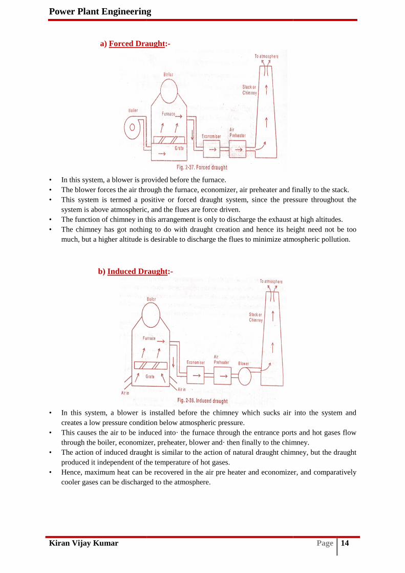
a) Forced Draught
• In this system, a blower is provided before the furnace. • The blower forces the air through the furnace, economizer, air preheater and finally to the stack. • This system is termed a positive or forced draught system, since the pressure throughout the
system is above atmospheric, and the flues are force driven. • The function of chimney in this arrangement is only to discharge the exhaust at high altitudes. • The chimney has got nothing to do with draught creation and hence its height need not be too
much, but a higher altitude is desirable to discharge the flues to minimize atmospheric pollution.
b) Induced Draught
• In this system, a blower is installed before the chimney which sucks air into the system and creates a low pressure condition below atmospheric pressure.
• This causes the air to be induced into· the furnace through the entrance ports and hot gases flow through the boiler, economizer, preheater, blower and· then finally to the chimney.
• The action of induced draught is similar to the action of natural draught chimney, but the draught produced it independent of the temperature of hot gases.
• Hence, maximum heat can be recovered in the air pre heater and economizer, and comparatively cooler gases can be discharged to the atmosphere.
Power Plant Engineering
Forced Draught:-
In this system, a blower is provided before the furnace. The blower forces the air through the furnace, economizer, air preheater and finally to the stack. This system is termed a positive or forced draught system, since the pressure throughout the system is above atmospheric, and the flues are force driven. The function of chimney in this arrangement is only to discharge the exhaust at high altitudes. The chimney has got nothing to do with draught creation and hence its height need not be too much, but a higher altitude is desirable to discharge the flues to minimize atmospheric pollution.
Induced Draught:-
In this system, a blower is installed before the chimney which sucks air into the system and creates a low pressure condition below atmospheric pressure. This causes the air to be induced into· the furnace through the entrance ports and hot gases flow
ough the boiler, economizer, preheater, blower and· then finally to the chimney. The action of induced draught is similar to the action of natural draught chimney, but the draught produced it independent of the temperature of hot gases.
heat can be recovered in the air pre heater and economizer, and comparatively cooler gases can be discharged to the atmosphere.
Page 14
The blower forces the air through the furnace, economizer, air preheater and finally to the stack. This system is termed a positive or forced draught system, since the pressure throughout the
The function of chimney in this arrangement is only to discharge the exhaust at high altitudes. The chimney has got nothing to do with draught creation and hence its height need not be too much, but a higher altitude is desirable to discharge the flues to minimize atmospheric pollution.
In this system, a blower is installed before the chimney which sucks air into the system and
This causes the air to be induced into· the furnace through the entrance ports and hot gases flow ough the boiler, economizer, preheater, blower and· then finally to the chimney.
The action of induced draught is similar to the action of natural draught chimney, but the draught
heat can be recovered in the air pre heater and economizer, and comparatively

Power Plant Engineering
Kiran Vijay Kumar
c) Balanced Draught
• Balanced draught is a combination of both forced draught and induced draught. • In this system, both forced draught and induced draught fans are used, thus eliminating the
difficulties of forced draught and induced draught systems. • The forced draught fan provided at the entry to the furnace supplies the air through the fuel
bed/grate, while the induced ddischarges them at the chimney.
• Forced draught supplies sufficient air for combustion and induced draught prevents blow off flames when the doors are opened
Comparison between Forced Draught and Indu1) The induced draught handles a higher volume of gases at high temperature, therefore the size of fan
required and power to drive it are larger as compared to· the forced draught system. 2) Water cooled bearings are required in induced
fan. 3) There are chances of air leakage in the forced draught system, since the pressure inside the furnace is
above atmospheric. In the induced draught, the pressure is below atmospheric (suction),chances of leakage.
4) In the induced draught system, air flow is more uniform through the grate and furnace, as compared to the forced draught system.
5) In an induced draught system, cold air may rush into the furnace while fuel charging dThis cold air rush will reduce the heat transfer efficiency.
6) The fan blade wear is more in induced draught system as the blades come in contact with hot gases.
Advantages of Mechanical Draught over Natural Draught1) In a mechanical draught system, the rate of combustion is high since high draught is available. 2) The rate of air flow, hence the combustion can be controlled by changing the draught pressures through the
fan operations. 3) The operation of the mechanical dra
However, the natural draught is highly dependent on the environmental temperature. 4) Low grade fuels can be easily burnt in mechanical draught system since a higher level of draught is
available in a mechanical draught system. 5) In mechanical draughts, maximum heat can be recovered and hence the overall efficiency is higher. 6) The chimney height need not be as high as that of natural draught as its function is only to discharge the
flues.
Power Plant Engineering
Balanced Draught:-
Balanced draught is a combination of both forced draught and induced draught. forced draught and induced draught fans are used, thus eliminating the
difficulties of forced draught and induced draught systems. The forced draught fan provided at the entry to the furnace supplies the air through the fuel bed/grate, while the induced draught fan sucks in the hot flues from the furnace and discharges them at the chimney. Forced draught supplies sufficient air for combustion and induced draught prevents blow off flames when the doors are opened
Comparison between Forced Draught and Induced Draught Systems:-The induced draught handles a higher volume of gases at high temperature, therefore the size of fan required and power to drive it are larger as compared to· the forced draught system. Water cooled bearings are required in induced draught system since the hot gases come in contact with the
There are chances of air leakage in the forced draught system, since the pressure inside the furnace is above atmospheric. In the induced draught, the pressure is below atmospheric (suction),
In the induced draught system, air flow is more uniform through the grate and furnace, as compared to the
In an induced draught system, cold air may rush into the furnace while fuel charging dThis cold air rush will reduce the heat transfer efficiency. The fan blade wear is more in induced draught system as the blades come in contact with hot gases.
Advantages of Mechanical Draught over Natural Draught:- In a mechanical draught system, the rate of combustion is high since high draught is available. The rate of air flow, hence the combustion can be controlled by changing the draught pressures through the
The operation of the mechanical draught system does not depend on the environmental temperature. However, the natural draught is highly dependent on the environmental temperature. Low grade fuels can be easily burnt in mechanical draught system since a higher level of draught is
in a mechanical draught system. In mechanical draughts, maximum heat can be recovered and hence the overall efficiency is higher. The chimney height need not be as high as that of natural draught as its function is only to discharge the
Page 15
Balanced draught is a combination of both forced draught and induced draught.
forced draught and induced draught fans are used, thus eliminating the
The forced draught fan provided at the entry to the furnace supplies the air through the fuel raught fan sucks in the hot flues from the furnace and
Forced draught supplies sufficient air for combustion and induced draught prevents blow off
- The induced draught handles a higher volume of gases at high temperature, therefore the size of fan required and power to drive it are larger as compared to· the forced draught system.
draught system since the hot gases come in contact with the
There are chances of air leakage in the forced draught system, since the pressure inside the furnace is above atmospheric. In the induced draught, the pressure is below atmospheric (suction), hence there are no
In the induced draught system, air flow is more uniform through the grate and furnace, as compared to the
In an induced draught system, cold air may rush into the furnace while fuel charging doors are opened.
The fan blade wear is more in induced draught system as the blades come in contact with hot gases.
In a mechanical draught system, the rate of combustion is high since high draught is available. The rate of air flow, hence the combustion can be controlled by changing the draught pressures through the
ught system does not depend on the environmental temperature. However, the natural draught is highly dependent on the environmental temperature. Low grade fuels can be easily burnt in mechanical draught system since a higher level of draught is
In mechanical draughts, maximum heat can be recovered and hence the overall efficiency is higher. The chimney height need not be as high as that of natural draught as its function is only to discharge the

Power Plant Engineering
Kiran Vijay Kumar
Boiler Accessories:-
• A boiler requires many accessories for continuous troublegeneration.
• Some accessories are needed to increase the efficiency of the boiler. • High economy in power generation can be achieved by utilizing the heat ene
maximum extent. Some of the essential boiler accessories as follows,
1. Super heater 2. Re heater 3. Economizer 4. Air pre heater
Other essential accessories include:1. De super heater 2. Soot blower
1. Super heater:-
• As the name implies, the
the boiler. • The steam generated in a boiler is not fully saturated, it contains some water particles
(dryness fraction will be less than 1). • If used directly, the water particles in the wet steam cause corrosion of the turbine blades,
lead to reduced turbine efficien• The super heater completely saturates the wet steam (produces dry steam) and increases its
temperature. • A superheated steam has high heat content, and hence has an increased capacity to do work. • This in turn improves the overall efficiency of the power plant. • The super heaters are made of steel tubes of 25 to 50 mm diameter, and formed in series of U
shapes. • Super heaters can be classified based on the heat transfer method. • There are three types of super heaters, as follows:
Power Plant Engineering
A boiler requires many accessories for continuous trouble-free functioning and steam
Some accessories are needed to increase the efficiency of the boiler. High economy in power generation can be achieved by utilizing the heat ene
Some of the essential boiler accessories useful for waste heat recovery, in the sequence, are
Other essential accessories include:-
As the name implies, the function of a super heater is to superheat the steam coming from
The steam generated in a boiler is not fully saturated, it contains some water particles (dryness fraction will be less than 1). If used directly, the water particles in the wet steam cause corrosion of the turbine blades, lead to reduced turbine efficiency, life and later failure of the blades itselfThe super heater completely saturates the wet steam (produces dry steam) and increases its temperature. A superheated steam has high heat content, and hence has an increased capacity to do work. This in turn improves the overall efficiency of the power plant. The super heaters are made of steel tubes of 25 to 50 mm diameter, and formed in series of U
Super heaters can be classified based on the heat transfer method. There are three types of super heaters, as follows:
Page 16
free functioning and steam
High economy in power generation can be achieved by utilizing the heat energy to the
, in the sequence, are
the steam coming from
The steam generated in a boiler is not fully saturated, it contains some water particles
If used directly, the water particles in the wet steam cause corrosion of the turbine blades, cy, life and later failure of the blades itself
The super heater completely saturates the wet steam (produces dry steam) and increases its
A superheated steam has high heat content, and hence has an increased capacity to do work.
The super heaters are made of steel tubes of 25 to 50 mm diameter, and formed in series of U

Power Plant Engineering
Kiran Vijay Kumar
a) Convective super heater
• Absorbs heat from the hot gases by convection.• This is the primary super heater that receives nearly saturated steam from the boiler drum. • This super heater is located in the convective zone of the furnace, just before the economizer.
b) Radiant super heater -
• Absorbs heat from the hot gases• This is the secondary super heater that receives steam from the primary super heater. • This super heater is located in the radiant zone of the furnace, adjacent to tile water wall so
that it absorbs heat by radiation.
c) Combined convective and radiant super heater • Absorbs heat both by convection and radiation from the hot gases. • This is also termed the pendant super heater, and is another secondary super heater used in
steam power plants. • Usually the steam from the rad
quality water is directly sprayed on to the steam. • The de super heater maintains the required temperature in the steam after passing through the
final stage or the pendant super heater.
2. Re-heater:-
• In a boiler, the super heaters are used to superheat the steam before being expanded in the high pressure (HP) turbine.
• The steam from the HP turbine loses the pressure and temperature. • This steam before being sent to the next stage (intermediate IP or low pressure LP) turbine, it
need to be improved again, this is done by passing this steam through a re heater. • Thus, a re-heater is similar to a super heater, except that it adds heat to
the HP turbine, before being expanded in the IP or LP turbine. • A re heater is generally located above the primary or convective super heater in the path of the hot
flues. • It is made of steel tubes mounted horizontally, perpendicular to the flue direction.
Power Plant Engineering
super heater- Absorbs heat from the hot gases by convection. This is the primary super heater that receives nearly saturated steam from the boiler drum. This super heater is located in the convective zone of the furnace, just before the economizer.
Absorbs heat from the hot gases by radiation. This is the secondary super heater that receives steam from the primary super heater. This super heater is located in the radiant zone of the furnace, adjacent to tile water wall so that it absorbs heat by radiation.
Combined convective and radiant super heater - Absorbs heat both by convection and radiation from the hot gases. This is also termed the pendant super heater, and is another secondary super heater used in
Usually the steam from the radiant super heater passes through a de super heater, where high quality water is directly sprayed on to the steam. The de super heater maintains the required temperature in the steam after passing through the
stage or the pendant super heater.
In a boiler, the super heaters are used to superheat the steam before being expanded in the high
The steam from the HP turbine loses the pressure and temperature. This steam before being sent to the next stage (intermediate IP or low pressure LP) turbine, it need to be improved again, this is done by passing this steam through a re heater.
heater is similar to a super heater, except that it adds heat to the steam coming out of the HP turbine, before being expanded in the IP or LP turbine. A re heater is generally located above the primary or convective super heater in the path of the hot
s mounted horizontally, perpendicular to the flue direction.
Page 17
This is the primary super heater that receives nearly saturated steam from the boiler drum. This super heater is located in the convective zone of the furnace, just before the economizer.
This is the secondary super heater that receives steam from the primary super heater. This super heater is located in the radiant zone of the furnace, adjacent to tile water wall so
This is also termed the pendant super heater, and is another secondary super heater used in
iant super heater passes through a de super heater, where high quality water is directly sprayed on to the steam. The de super heater maintains the required temperature in the steam after passing through the
In a boiler, the super heaters are used to superheat the steam before being expanded in the high
This steam before being sent to the next stage (intermediate IP or low pressure LP) turbine, it need to be improved again, this is done by passing this steam through a re heater.
the steam coming out of
A re heater is generally located above the primary or convective super heater in the path of the hot
s mounted horizontally, perpendicular to the flue direction.

Power Plant Engineering
Kiran Vijay Kumar
3. Economizer:-
• The function of an economizer is to heat the feed water, before being supplied to the boiler, using the products of combustion discharged from the boiler.
• Generally feed water is heated 20• The economizer makes use of waste flues; recovers heat energy and hence the name
economizer. • Thus the economizer increases the boiler efficiency.• As an approximation, it is shown that the boiler efficiency increases by 1% for every 6°C
raise in the feed water temperature• The flues passing through the economizer chamber transfer the heat energy to the water
flowing through the steel tubes. • The maximum temperature desir
above 85°C the steam bubbles begin to form and the feed pump cannot supply steammixture properly.
• To overcome this problem the feed water pump is generally located before the economizer.• The feed water pump pumps either raw water (after proper treatment) or condensate from the
condenser. • The feed water flowing through the economizer gets heated and enters the boiler under
pressure. • A non-return valve is provided to avoid return flow of f
when the feed pump is not in operation.• The pump pressure is always higher (about 2 bar more) the boiler pressure in operation.
Advantages of Economizer
1) It recovers the waste heat to a greater extent. 2) It reduces the fuel consumption per unit power produced. 3) It improves the efficiency of the power plant.4) It reduces the soot and fly
Power Plant Engineering
The function of an economizer is to heat the feed water, before being supplied to the boiler, using the products of combustion discharged from the boiler. Generally feed water is heated 20-30°C below the boiling point. The economizer makes use of waste flues; recovers heat energy and hence the name economizer. Thus the economizer increases the boiler efficiency.
it is shown that the boiler efficiency increases by 1% for every 6°C raise in the feed water temperature The flues passing through the economizer chamber transfer the heat energy to the water flowing through the steel tubes. The maximum temperature desirable is 20 – 300C below the boiling point, as at temperatures above 85°C the steam bubbles begin to form and the feed pump cannot supply steam
To overcome this problem the feed water pump is generally located before the economizer.The feed water pump pumps either raw water (after proper treatment) or condensate from the
The feed water flowing through the economizer gets heated and enters the boiler under
return valve is provided to avoid return flow of feed water or steam from the boiler, when the feed pump is not in operation. The pump pressure is always higher (about 2 bar more) the boiler pressure in operation.
Advantages of Economizer:- 1) It recovers the waste heat to a greater extent.
uces the fuel consumption per unit power produced. 3) It improves the efficiency of the power plant. 4) It reduces the soot and fly-ash being discharged to atmosphere to some extent.
Page 18
The function of an economizer is to heat the feed water, before being supplied to the boiler,
The economizer makes use of waste flues; recovers heat energy and hence the name
it is shown that the boiler efficiency increases by 1% for every 6°C
The flues passing through the economizer chamber transfer the heat energy to the water
C below the boiling point, as at temperatures above 85°C the steam bubbles begin to form and the feed pump cannot supply steam-water
To overcome this problem the feed water pump is generally located before the economizer. The feed water pump pumps either raw water (after proper treatment) or condensate from the
The feed water flowing through the economizer gets heated and enters the boiler under
eed water or steam from the boiler,
The pump pressure is always higher (about 2 bar more) the boiler pressure in operation.
ash being discharged to atmosphere to some extent.

Power Plant Engineering
Kiran Vijay Kumar
4. Air pre heater:-
• The function of an air preheater, as the name indicates, is to preheat the air being supplied to the furnace for combustion.
• This makes use of the flues discharged from the furnace and from the economizer. • As this also recovers further heat from the flue• An increase in temperature of the 20°C increases the boiler efficiency by 1 %. Advantages:-
1) Combustion efficiency is improved. 2) Low grade fuels can be burnt successfully. 3) Steam rising capacity is increased. 4) Fuel consumption is reduced.
Special accessories,
1. Desuperheater:-
Power Plant Engineering
The function of an air preheater, as the name indicates, is to preheat the air being supplied to the furnace for combustion. This makes use of the flues discharged from the furnace and from the economizer. As this also recovers further heat from the flues, it increases the boiler efficiency. An increase in temperature of the 20°C increases the boiler efficiency by 1 %.
1) Combustion efficiency is improved. 2) Low grade fuels can be burnt successfully. 3) Steam rising capacity is increased. 4) Fuel consumption is reduced.
Page 19
The function of an air preheater, as the name indicates, is to preheat the air being supplied to
This makes use of the flues discharged from the furnace and from the economizer. s, it increases the boiler efficiency.
An increase in temperature of the 20°C increases the boiler efficiency by 1 %.

Power Plant Engineering
Kiran Vijay Kumar
• It is essential to control the superheat temperature, otherwise it may lead to overheating of superheated tubes and initial stages of the turbine, causing operational problems.
• The device used to control the superheat temperature is termed a desuperheater• The various methods used to control the superheat temperatures are as follows:
1) Bypassing the hot gases. When the temperature of the superheated steam raises sufficiently high, then the hot gases are bypassed with the help of dampers.
• Cooling water is essential in a steam power plant to condense the steam from the steam turbines. • The quantity of cooling water required is so high that it cannot be let out after use. • A 100 MW plant needs about 10,000 tones of cooling water per day. • This necessitates the need for recirculation of the cooling water. • The used water absorbs heat from the condenser and cannot be recirculated unless cooled to a
minimum temperature.
Cooling Towers:-
The different types of cooling towers used in power plants are:
1. Wet type a) Natural draught cooling tower b) Forced draught cooling tower c) Induced draught cooling tower
2. Dry type a) Direct type b) Indirect type
1. Wet type:-
a) Natural draught cooling tower
• This is a wet type of cooling tower, and is generally used in large capacity power plants. • It consists of a huge hyperbolic concrete structure, with openings at the bottom.• At the lowest portion of the structure a water pond is constructed for the collect
cooling water. • In operation, the cooling water from the condenser is to the top of the cooling tower. • The water is sprayed from the top, and falls sprinkles. • Because of the height, natural draught is created and the air rises bottom. • The falling water comes in contact with the rising air and gets cooled water is collected in the
pond and pumped back to the condenser. • Make up water is added to the pond periodically. • The height of the cooling tower ranges from 50 m to 80 m, with base diameter
Power Plant Engineering
It is essential to control the superheat temperature, otherwise it may lead to overheating of superheated tubes and initial stages of the turbine, causing operational problems. The device used to control the superheat temperature is termed a desuperheaterThe various methods used to control the superheat temperatures are as follows: 1) Bypassing the hot gases. When the temperature of the superheated steam raises sufficiently
high, then the hot gases are bypassed with the help of dampers. is essential in a steam power plant to condense the steam from the steam turbines.
The quantity of cooling water required is so high that it cannot be let out after use. A 100 MW plant needs about 10,000 tones of cooling water per day.
the need for recirculation of the cooling water. The used water absorbs heat from the condenser and cannot be recirculated unless cooled to a
The different types of cooling towers used in power plants are:
a) Natural draught cooling tower b) Forced draught cooling tower c) Induced draught cooling tower
Natural draught cooling tower:-
This is a wet type of cooling tower, and is generally used in large capacity power plants. It consists of a huge hyperbolic concrete structure, with openings at the bottom.At the lowest portion of the structure a water pond is constructed for the collect
In operation, the cooling water from the condenser is to the top of the cooling tower. The water is sprayed from the top, and falls sprinkles. Because of the height, natural draught is created and the air rises bottom.
ing water comes in contact with the rising air and gets cooled water is collected in the pond and pumped back to the condenser. Make up water is added to the pond periodically. The height of the cooling tower ranges from 50 m to 80 m, with base diameter
Page 20
It is essential to control the superheat temperature, otherwise it may lead to overheating of superheated tubes and initial stages of the turbine, causing operational problems. The device used to control the superheat temperature is termed a desuperheater. The various methods used to control the superheat temperatures are as follows: 1) Bypassing the hot gases. When the temperature of the superheated steam raises sufficiently
is essential in a steam power plant to condense the steam from the steam turbines. The quantity of cooling water required is so high that it cannot be let out after use.
The used water absorbs heat from the condenser and cannot be recirculated unless cooled to a
This is a wet type of cooling tower, and is generally used in large capacity power plants. It consists of a huge hyperbolic concrete structure, with openings at the bottom. At the lowest portion of the structure a water pond is constructed for the collection of the
In operation, the cooling water from the condenser is to the top of the cooling tower.
Because of the height, natural draught is created and the air rises bottom. ing water comes in contact with the rising air and gets cooled water is collected in the
The height of the cooling tower ranges from 50 m to 80 m, with base diameter up to 40 m.

Power Plant Engineering
Kiran Vijay Kumar
b) Forced draught cooling tower
• Forced draught cooling towers are smaller in size and are used in small capacity power plants. • Since the height of the cooling tower is smaller and it has a rectangular section, the natural
draught created very low. • Hence, to create a draught, a forced draught a fan is provided at the bottom• The cooling tower is a rectangular section having baffles• A forced draught fan is provided at the bottom, and it pressurizes the air. • The hot water from the condenser is sprayed from the top and while falling through the
baffles/obstacles it comes in contact with the raising forced dr• The cooled water is collected in the pond and re circulated. • Make up water is added to the pond periodically
c) Induced draught cooling tower• This is similar in construction and operation to a forced draught cooling tower,
induced draught fan. • This is suitable for small capacity power plants. • It has a rectangular section with opening at the bottom for the air entry. • In operation the induced draught fan sucks air through the baffles from the openings at the
bottom of the tower. • The hot water pumped from the condenser is sprayed at the top. • The falling water comes in contact with the raising air and gets cooled. • The cooled water is collected in the pond and pumped back to the condenser. • Make up water is added periodically to the pond.
Power Plant Engineering
Forced draught cooling tower:-
Forced draught cooling towers are smaller in size and are used in small capacity power plants. Since the height of the cooling tower is smaller and it has a rectangular section, the natural draught created very low. Hence, to create a draught, a forced draught a fan is provided at the bottomThe cooling tower is a rectangular section having baffles/obstruction at the centre.A forced draught fan is provided at the bottom, and it pressurizes the air. The hot water from the condenser is sprayed from the top and while falling through the baffles/obstacles it comes in contact with the raising forced draught air and gets cooled. The cooled water is collected in the pond and re circulated. Make up water is added to the pond periodically
Induced draught cooling tower:- This is similar in construction and operation to a forced draught cooling tower,
This is suitable for small capacity power plants. It has a rectangular section with opening at the bottom for the air entry. In operation the induced draught fan sucks air through the baffles from the openings at the
The hot water pumped from the condenser is sprayed at the top. The falling water comes in contact with the raising air and gets cooled.
cooled water is collected in the pond and pumped back to the condenser. Make up water is added periodically to the pond.
Page 21
Forced draught cooling towers are smaller in size and are used in small capacity power plants. Since the height of the cooling tower is smaller and it has a rectangular section, the natural
Hence, to create a draught, a forced draught a fan is provided at the bottom /obstruction at the centre.
A forced draught fan is provided at the bottom, and it pressurizes the air. The hot water from the condenser is sprayed from the top and while falling through the
aught air and gets cooled.
This is similar in construction and operation to a forced draught cooling tower, except for the
In operation the induced draught fan sucks air through the baffles from the openings at the
cooled water is collected in the pond and pumped back to the condenser.

Power Plant Engineering
Kiran Vijay Kumar
3. Dry type:- a) Direct type:-
• In this, the exhaust steam is collected in a large steam header at the top. • A number of steel tubes
to the condensate header at the bottom.• The steam tubes are provided with external fins, so as to increase the heat transfer rate and
hence condense the steam in the tubes. • The steam condenses as water in the condensate headers, and is collected in a condensate
tank. • From the tank the water is pumped to the feed water line.
b) Indirect type:- There are two types of indirect dry cooling towers.
i) Indirect dry cooling tower with a conventional surface condenser
Power Plant Engineering
In this, the exhaust steam is collected in a large steam header at the top. are connected to the steam header, through which the steam is passed
to the condensate header at the bottom. The steam tubes are provided with external fins, so as to increase the heat transfer rate and hence condense the steam in the tubes.
ndenses as water in the condensate headers, and is collected in a condensate
From the tank the water is pumped to the feed water line.
There are two types of indirect dry cooling towers.
Indirect dry cooling tower with a conventional surface condenser
Page 22
are connected to the steam header, through which the steam is passed
The steam tubes are provided with external fins, so as to increase the heat transfer rate and
ndenses as water in the condensate headers, and is collected in a condensate
Indirect dry cooling tower with a conventional surface condenser

Power Plant Engineering
Kiran Vijay Kumar
• This cooling tower uses two heat exchangers in series. • The first one is the conventional surface condenser, where the turbine exhaust steam is
condensed using cooling water as the coolant• The condensate is used as feed water. • The second heat exchanger is the hot water to air heat exchanger, in which the hot water from
the surface condenser is cooled with the help of finned tubing similar to the dry cooling tower concept.
• The steam at temperature Ts from the turbine is first condensed in the surface condenser. • At this heat exchanger by absorbing heat from steam, the water temperature raises from T1 to
T2. • The hot water is (at T2) then passed through a series of steel tubes in the dry co• The steel tubing is provided with external fins, so as to increase the heat transfer rate and
hence cool the hot water in the tubes. • The cooling is assisted in the tower with the help of two 10 fans (or a large hyperbolic natural
draught tower can also be used, depending upon the cooling requirements).
ii) Indirect dry cooling tower with a open type condenser
• The construction and operation of this cooling tower is same as the dry indirect cooling tower with surface condenser, except that it uses a open spray type condenser instead of the surface condenser.
• Thus this cooling tower also uses two heat exchangers • The first one is a direct contact spray type steam condenser, where the turbine exhaust steam
is condensed using cooling water. The second heat exchanger is indirect type, the hot water to air heat exchanger, in which the hot water from the condfinned tubing similar to the dry cooling tower concept.
• A part of the hot water is used as feed water. • The steam at a higher temperature from the turbine is first condensed in the spray type
condenser.
Power Plant Engineering
This cooling tower uses two heat exchangers in series. The first one is the conventional surface condenser, where the turbine exhaust steam is condensed using cooling water as the coolant. The condensate is used as feed water. The second heat exchanger is the hot water to air heat exchanger, in which the hot water from the surface condenser is cooled with the help of finned tubing similar to the dry cooling tower
emperature Ts from the turbine is first condensed in the surface condenser. At this heat exchanger by absorbing heat from steam, the water temperature raises from T1 to
The hot water is (at T2) then passed through a series of steel tubes in the dry coThe steel tubing is provided with external fins, so as to increase the heat transfer rate and hence cool the hot water in the tubes. The cooling is assisted in the tower with the help of two 10 fans (or a large hyperbolic natural
er can also be used, depending upon the cooling requirements).
Indirect dry cooling tower with a open type condenser
The construction and operation of this cooling tower is same as the dry indirect cooling tower with surface condenser, except that it uses a open spray type condenser instead of the surface
Thus this cooling tower also uses two heat exchangers in series. The first one is a direct contact spray type steam condenser, where the turbine exhaust steam is condensed using cooling water. The second heat exchanger is indirect type, the hot water to air heat exchanger, in which the hot water from the condenser is cooled with the help of finned tubing similar to the dry cooling tower concept. A part of the hot water is used as feed water. The steam at a higher temperature from the turbine is first condensed in the spray type
Page 23
The first one is the conventional surface condenser, where the turbine exhaust steam is
The second heat exchanger is the hot water to air heat exchanger, in which the hot water from the surface condenser is cooled with the help of finned tubing similar to the dry cooling tower
emperature Ts from the turbine is first condensed in the surface condenser. At this heat exchanger by absorbing heat from steam, the water temperature raises from T1 to
The hot water is (at T2) then passed through a series of steel tubes in the dry cooling tower. The steel tubing is provided with external fins, so as to increase the heat transfer rate and
The cooling is assisted in the tower with the help of two 10 fans (or a large hyperbolic natural er can also be used, depending upon the cooling requirements).
The construction and operation of this cooling tower is same as the dry indirect cooling tower with surface condenser, except that it uses a open spray type condenser instead of the surface
The first one is a direct contact spray type steam condenser, where the turbine exhaust steam is condensed using cooling water. The second heat exchanger is indirect type, the hot water to
enser is cooled with the help of
The steam at a higher temperature from the turbine is first condensed in the spray type

Power Plant Engineering
Kiran Vijay Kumar
• At this heat exchanger by mixing with steam, the water temperature raises from Twater-steam mixture attains the same temperature.
• The hot water is (at T2) then passed through a series of steel tubes in the drying tower. • The steel tubing are provided with external f
cool the hot water in the tubes. • The cooling is assisted in tower with the help of two ID fans (or a large hyperbolic natural
draught tower also be used, depending upon the cooling requirements). • At this cooling tower, the water temperature drops from T• Since the heat is absorbed by the cooling he air gains temperature from T• These temperature path lengths at the condenser and the cooling tower.
Pondage:-
It is defined as a regulatingcollection of the excess flow water from the dam spill ways of the main reservoir or from/the river stream.
• It is basically a small pond or reservoir just behind the power house as shown in fi• The amount of regulation obtained with pondage usually involves storing water during low
loads (during low power demand periods such as early morning hours and Sundays) to aid carrying peak loads during the week.
• The water that would go over the daadded to normal river flow to supply peak loads, usually for a few hours of duration
• For fluctuating loads, pondage increases the maximum capacity that a plant can carry. • Plants with reservoirs upstream can store excess water of spring floods for release during
summer to supplement the low rates of flow during this dry season• Reservoir water elevation will generally be lowest during the year at the end of the summer. • Pondage increases the capaci• But, storage increases the capacity of a river over an extended period such like 6 months to 2
year.
Power Plant Engineering
ger by mixing with steam, the water temperature raises from Tsteam mixture attains the same temperature.
) then passed through a series of steel tubes in the drying tower. The steel tubing are provided with external fins, so as to increase the transfer rate and hence cool the hot water in the tubes. The cooling is assisted in tower with the help of two ID fans (or a large hyperbolic natural draught tower also be used, depending upon the cooling requirements).
cooling tower, the water temperature drops from T2 to T1. Since the heat is absorbed by the cooling he air gains temperature from TThese temperature path lengths at the condenser and the cooling tower.
It is defined as a regulating means of water, and is a small reservoir that is used for the collection of the excess flow water from the dam spill ways of the main reservoir or from/the
It is basically a small pond or reservoir just behind the power house as shown in fiThe amount of regulation obtained with pondage usually involves storing water during low loads (during low power demand periods such as early morning hours and Sundays) to aid carrying peak loads during the week. The water that would go over the dam spill-way unused during low-loads can be released and added to normal river flow to supply peak loads, usually for a few hours of durationFor fluctuating loads, pondage increases the maximum capacity that a plant can carry.
upstream can store excess water of spring floods for release during summer to supplement the low rates of flow during this dry season Reservoir water elevation will generally be lowest during the year at the end of the summer. Pondage increases the capacity of a river for a brief period only, like for 8 week. But, storage increases the capacity of a river over an extended period such like 6 months to 2
Page 24
ger by mixing with steam, the water temperature raises from T1 to T2
) then passed through a series of steel tubes in the drying tower. ins, so as to increase the transfer rate and hence
The cooling is assisted in tower with the help of two ID fans (or a large hyperbolic natural
3 to T4.
means of water, and is a small reservoir that is used for the collection of the excess flow water from the dam spill ways of the main reservoir or from/the
It is basically a small pond or reservoir just behind the power house as shown in figure. The amount of regulation obtained with pondage usually involves storing water during low loads (during low power demand periods such as early morning hours and Sundays) to aid
loads can be released and added to normal river flow to supply peak loads, usually for a few hours of duration For fluctuating loads, pondage increases the maximum capacity that a plant can carry.
upstream can store excess water of spring floods for release during
Reservoir water elevation will generally be lowest during the year at the end of the summer. ty of a river for a brief period only, like for 8 week.
But, storage increases the capacity of a river over an extended period such like 6 months to 2
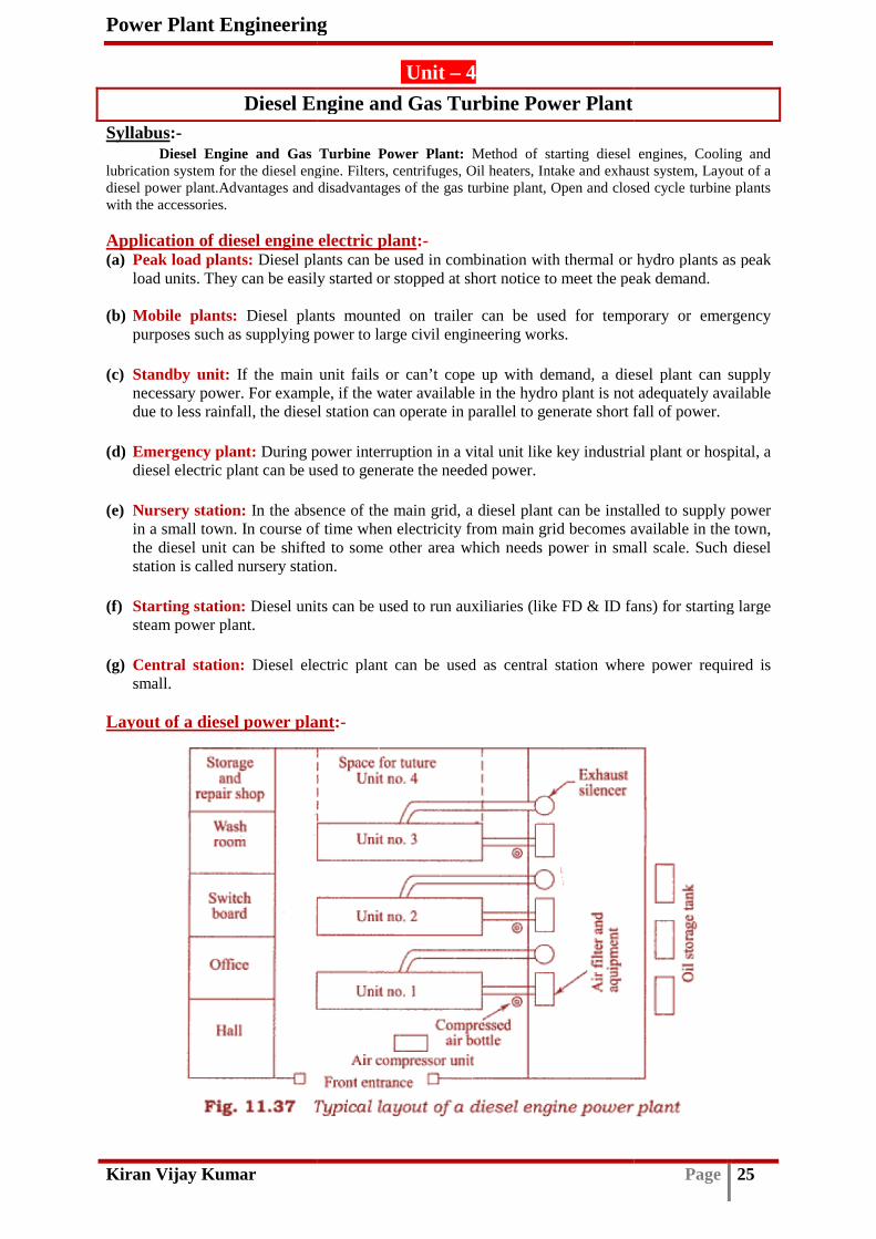
Power Plant Engineering
Kiran Vijay Kumar
Diesel Engine and Gas Turbine Power PlantSyllabus:-
Diesel Engine and Gas Turbine Power Plant: lubrication system for the diesel engine. Filters, centrifuges, Oil heaters, Intake and exhaust system,diesel power plant.Advantages and disadvantages ofwith the accessories. Application of diesel engine electric plant(a) Peak load plants: Diesel plants can be used in combination with thermal or hydro plants as peak
load units. They can be easily started or stopped at short notice to meet the peak demand. (b) Mobile plants: Diesel plants mounted on trailer can be used for temporary or emergenc
purposes such as supplying power to large civil engineering works.
(c) Standby unit: If the main unit fails or can’t cope up with demand, a diesel plant can supply necessary power. For example, if the water available in the hydro plant is not adequately avadue to less rainfall, the diesel station can operate in parallel to generate short fall of power.
(d) Emergency plant: During power interruption in a vital unit like key industrial plant or hospital, a
diesel electric plant can be used to generate the
(e) Nursery station: In the absence of the main grid, a diesel plant can be installed to supply power in a small town. In course of time when electricity from main grid becomes available in the town, the diesel unit can be shifted to some otherstation is called nursery station.
(f) Starting station: Diesel units can be used to run auxiliaries (like FD & ID fans) for starting large
steam power plant.
(g) Central station: Diesel electric plant can be usmall.
Layout of a diesel power plant
Power Plant Engineering
Unit – 4
Diesel Engine and Gas Turbine Power Plant
Diesel Engine and Gas Turbine Power Plant: Method of starting diesel engines, Cooling and diesel engine. Filters, centrifuges, Oil heaters, Intake and exhaust system,
diesel power plant.Advantages and disadvantages of the gas turbine plant, Open and closed cycle turbine plants
Application of diesel engine electric plant:- Diesel plants can be used in combination with thermal or hydro plants as peak
load units. They can be easily started or stopped at short notice to meet the peak demand.
Diesel plants mounted on trailer can be used for temporary or emergencpurposes such as supplying power to large civil engineering works.
If the main unit fails or can’t cope up with demand, a diesel plant can supply necessary power. For example, if the water available in the hydro plant is not adequately avadue to less rainfall, the diesel station can operate in parallel to generate short fall of power.
During power interruption in a vital unit like key industrial plant or hospital, a diesel electric plant can be used to generate the needed power.
In the absence of the main grid, a diesel plant can be installed to supply power in a small town. In course of time when electricity from main grid becomes available in the town, the diesel unit can be shifted to some other area which needs power in small scale. Such diesel station is called nursery station.
Diesel units can be used to run auxiliaries (like FD & ID fans) for starting large
Diesel electric plant can be used as central station where power required is
Layout of a diesel power plant:-
Page 25
Method of starting diesel engines, Cooling and diesel engine. Filters, centrifuges, Oil heaters, Intake and exhaust system, Layout of a
turbine plant, Open and closed cycle turbine plants
Diesel plants can be used in combination with thermal or hydro plants as peak load units. They can be easily started or stopped at short notice to meet the peak demand.
Diesel plants mounted on trailer can be used for temporary or emergency
If the main unit fails or can’t cope up with demand, a diesel plant can supply necessary power. For example, if the water available in the hydro plant is not adequately available due to less rainfall, the diesel station can operate in parallel to generate short fall of power.
During power interruption in a vital unit like key industrial plant or hospital, a
In the absence of the main grid, a diesel plant can be installed to supply power in a small town. In course of time when electricity from main grid becomes available in the town,
area which needs power in small scale. Such diesel
Diesel units can be used to run auxiliaries (like FD & ID fans) for starting large
sed as central station where power required is

Power Plant Engineering
Kiran Vijay Kumar
• The layout of a diesel engine power plant is shown in above figure. • Diesel engine units are installed side by side with some room left fur extension in the future• The repairs and usual maintenance works require some space around the units. • The air intakes and filters are exhaust mufflers are located outside. • Adequate space for oil storage, repair shop and office are provided as shown. • Bulk storage of Oil may be outdoors. Starting of engine:- Following are the three common method of starting an engine.i. By an auxiliary engine,
through a clutch and gears.ii. By using an electric motor,
to an electric motor that derives the engine.iii. By compressed air system,
is admitted to a few engine cylinders making them woengine shaft. Fuel is admitted to the remaining cylinders and ignited in the normal way causing the engine to start. The compressed air system is commonly used for starting large diesel engines employed for stati
Essential component or element of diesel electric plant
1. Engine 2. Air intake system 3. Exhaust system 4. Fuel system 5. Cooling system 6. Lubrication system
1. Engine:-
It is the main component of the plant and is directly coupled to the
2. Air intake system:-
It conveys fresh air through louvers and air filter that removes dirt, etc. causing wear of the engine. Supercharger, if fitted, is generally driven by the engine itself and it augments the power output of the engine.
Power Plant Engineering
The layout of a diesel engine power plant is shown in above figure. Diesel engine units are installed side by side with some room left fur extension in the futureThe repairs and usual maintenance works require some space around the units. The air intakes and filters are exhaust mufflers are located outside. Adequate space for oil storage, repair shop and office are provided as shown.
be outdoors.
Following are the three common method of starting an engine. By an auxiliary engine, this is mounted close to the main engine and drives the latter through a clutch and gears. By using an electric motor, in which a storage battery 12 to 36 volts is used to supply power to an electric motor that derives the engine. By compressed air system, in which compressed air at about 17bar supplied from an air tank is admitted to a few engine cylinders making them work like reciprocating air motors to run the engine shaft. Fuel is admitted to the remaining cylinders and ignited in the normal way causing the engine to start. The compressed air system is commonly used for starting large diesel engines employed for stationary power plant service.
Essential component or element of diesel electric plant:-
It is the main component of the plant and is directly coupled to the generator.
It conveys fresh air through louvers and air filter that removes dirt, etc. causing wear of the
engine. Supercharger, if fitted, is generally driven by the engine itself and it augments the power
Page 26
Diesel engine units are installed side by side with some room left fur extension in the future. The repairs and usual maintenance works require some space around the units.
Adequate space for oil storage, repair shop and office are provided as shown.
this is mounted close to the main engine and drives the latter
in which a storage battery 12 to 36 volts is used to supply power
in which compressed air at about 17bar supplied from an air tank rk like reciprocating air motors to run the
engine shaft. Fuel is admitted to the remaining cylinders and ignited in the normal way causing the engine to start. The compressed air system is commonly used for starting large diesel
generator.
It conveys fresh air through louvers and air filter that removes dirt, etc. causing wear of the engine. Supercharger, if fitted, is generally driven by the engine itself and it augments the power

Power Plant Engineering
Kiran Vijay Kumar
3. Exhaust system:-
• Exhaust system discharge the engine exhaust to the atmosphere. • The exhaust manifold connects the engine cylinder exhaust outlets to the exhaust pipe which is
provided with a muffler or silencer to reduce pressure on the exhaust line and eliminates most of the noise which may result if gases are discharged directly to
• The exhaust pipe should have flexible tubing system to take up the effects of expansion due to high temperature and also isolate the exhaust system from the engine vibration.
There is scope of waste heat utilization from the diesel engini. By installing a waste heat boiler to raise low pressure steam which can be used for any process,
purpose or for generating electricity. ii. The hot exhaust may also be utilized to heat water in a gas
in the form of a water coil installed in the exhaust muffler. iii. It can also be used for air heating where the exhaust pipe is surrounded by the cold air jacket.
4. Fuel system:-
• Fuel oil may be delivered at the plant site by trucks, railway wagons or barges and oil tankers. • An unloading facility delivers oil to the main storage tanks from where oil is pumped to small
service storage tanks known as engine day tanks, which store oiof operation.
• The fuel injection system is the heart of a diesel engine. • Engines driving electric generators have lower speeds and simple combustion chambers that
promote good mixing of fuel and air. 5. Cooling system:-
The temperature of the gases inside the cylinder may be as high as 2750"C. If there is no external cooling, the cylinder walls and piston will tend to assume the average temperature of the gases which may be of the order of 1000° to I500°C. The cooling of thefollowing reasons.
a) The lubricating oil used determines the maximum engine temperature that can be used. Above these temperatures the lubricating oil deteriorates very rapidly and may evaporate and bum damaging the piston and cy
b) The strength of the materials used for various engine parts decreases with increase in temperature.
c) High engine temperatures may result in very hot exhaust valve, giving rise to predetonation or knocking.
d) Due to high cylinder head temperature, the volumetric efficiency and hence power outputs of the engine are reduced.
Power Plant Engineering
Exhaust system discharge the engine exhaust to the atmosphere. The exhaust manifold connects the engine cylinder exhaust outlets to the exhaust pipe which is provided with a muffler or silencer to reduce pressure on the exhaust line and eliminates most of the noise which may result if gases are discharged directly to the atmosphere. The exhaust pipe should have flexible tubing system to take up the effects of expansion due to high temperature and also isolate the exhaust system from the engine vibration.
There is scope of waste heat utilization from the diesel engine exhaust, By installing a waste heat boiler to raise low pressure steam which can be used for any process, purpose or for generating electricity. The hot exhaust may also be utilized to heat water in a gas-to-water heat exchanger which can be
m of a water coil installed in the exhaust muffler. It can also be used for air heating where the exhaust pipe is surrounded by the cold air jacket.
Fuel oil may be delivered at the plant site by trucks, railway wagons or barges and oil tankers. An unloading facility delivers oil to the main storage tanks from where oil is pumped to small service storage tanks known as engine day tanks, which store oil for approximately eight hours
The fuel injection system is the heart of a diesel engine. Engines driving electric generators have lower speeds and simple combustion chambers that promote good mixing of fuel and air.
temperature of the gases inside the cylinder may be as high as 2750"C. If there is no external cooling, the cylinder walls and piston will tend to assume the average temperature of the gases which may be of the order of 1000° to I500°C. The cooling of the engine is necessary for the
The lubricating oil used determines the maximum engine temperature that can be used. Above these temperatures the lubricating oil deteriorates very rapidly and may evaporate and bum damaging the piston and cylinder surfaces. The strength of the materials used for various engine parts decreases with increase in
High engine temperatures may result in very hot exhaust valve, giving rise to pre
er head temperature, the volumetric efficiency and hence power outputs of
Page 27
The exhaust manifold connects the engine cylinder exhaust outlets to the exhaust pipe which is provided with a muffler or silencer to reduce pressure on the exhaust line and eliminates most
the atmosphere. The exhaust pipe should have flexible tubing system to take up the effects of expansion due to high temperature and also isolate the exhaust system from the engine vibration.
By installing a waste heat boiler to raise low pressure steam which can be used for any process,
water heat exchanger which can be
It can also be used for air heating where the exhaust pipe is surrounded by the cold air jacket.
Fuel oil may be delivered at the plant site by trucks, railway wagons or barges and oil tankers. An unloading facility delivers oil to the main storage tanks from where oil is pumped to small
l for approximately eight hours
Engines driving electric generators have lower speeds and simple combustion chambers that
temperature of the gases inside the cylinder may be as high as 2750"C. If there is no external cooling, the cylinder walls and piston will tend to assume the average temperature of the
engine is necessary for the
The lubricating oil used determines the maximum engine temperature that can be used. Above these temperatures the lubricating oil deteriorates very rapidly and may evaporate and bum
The strength of the materials used for various engine parts decreases with increase in
High engine temperatures may result in very hot exhaust valve, giving rise to pre-ignition and
er head temperature, the volumetric efficiency and hence power outputs of

Power Plant Engineering
Kiran Vijay Kumar
Following are the two methods of cooling the engine.(i) Air cooling:
Air cooling is used in small engines, where fins are provided to increase heat transfer surfarea.
(ii) Water cooling:Big diesel engines are always water cooled. The cylinder and its head are enclosed in a water
jacket which is connected to a radiator. Water flowing in the jacket carries away the heat from the engine and becomes heated. The hot waheat to air from the radiator walls. Cooled water is again circulated in the water jacket.
Various methods used for circulating the water around the cylinder are the following.(a) Thermosiphon cooling: In this method water flow is caused by density difference. The rate of'
circulation is slow and insufficient.
(b) Forced cooling by pump: In this method a pump, taking power from the engine, forces water to circulate, ensuring engine cooling under all operating conditions. There may be overcooling which may cause low temperature corrosion of metal parts due to the presence of acids.
(c) Thermostat cooling: This is a method in which a thermostat maintains the desired temperature and protects the engine from getting overcooled.
Power Plant Engineering
Following are the two methods of cooling the engine.
Air cooling is used in small engines, where fins are provided to increase heat transfer surf
Water cooling: Big diesel engines are always water cooled. The cylinder and its head are enclosed in a water
jacket which is connected to a radiator. Water flowing in the jacket carries away the heat from the engine and becomes heated. The hot water then flows into the radiator and gets cooled by rejecting heat to air from the radiator walls. Cooled water is again circulated in the water jacket.
Various methods used for circulating the water around the cylinder are the following.In this method water flow is caused by density difference. The rate of'
circulation is slow and insufficient.
In this method a pump, taking power from the engine, forces water to circulate, ensuring engine cooling under all operating conditions. There may be overcooling which may cause low temperature corrosion of metal parts due to the presence of acids.
This is a method in which a thermostat maintains the desired temperature and protects the engine from getting overcooled.
Page 28
Air cooling is used in small engines, where fins are provided to increase heat transfer surface
Big diesel engines are always water cooled. The cylinder and its head are enclosed in a water jacket which is connected to a radiator. Water flowing in the jacket carries away the heat from the
ter then flows into the radiator and gets cooled by rejecting heat to air from the radiator walls. Cooled water is again circulated in the water jacket.
Various methods used for circulating the water around the cylinder are the following. In this method water flow is caused by density difference. The rate of'
In this method a pump, taking power from the engine, forces water to circulate, ensuring engine cooling under all operating conditions. There may be overcooling which may cause low temperature corrosion of metal parts due to the presence of acids.
This is a method in which a thermostat maintains the desired temperature

Power Plant Engineering
Kiran Vijay Kumar
(d) Pressurized water cooling:increase heal transfer in the radiator. A pressure relief valve is provided against any pressure drop or vacuum.
(e) Evaporative cooling: In this method water is allowed to evaporate absorbing the latent heal of evaporation from the cylinder walls. The cooling circuit is such thand the steam flashes in a separate vessel.
6. Lubrication system:-
• Lubrication is the flow of oil between two surfaces having relative motion.• Following are the function of lubricating system.
(a) Lubrication: To keep moving parts sliding freely past each other, thus reducing engine friction and wear.
(b) Cooling: To keep the surface cool by taking away a part of heat caused by friction. (c) Cleaning: To keep bearing and friction ring clean of the product of wear and combustion by
washing them away. (d) Sealing: To form a good seal between the piston ring and cylinder wall.(e) Reduce noise: To reduce noise of engine by absorbing vibration.
Lubrication system can be classified as,
lubrication system and (c) Dry sump lubrication system.
(a) Mist lubrication system
This system is used for two stroke cycle engine which employs crankcase compression. Thus crankcase lubrica
(b) Wet sump lubrication system
The bottom part of the crankcase, called sump, contains the lubricating oil which is pumped to the various part of the engine. There are three types of wet sump lubrication system; they are Splash system, Modified splash system and Full pressure system
Power Plant Engineering
Pressurized water cooling: In this method a higher water pressure, 1.5 to 2bar, is maintained to er in the radiator. A pressure relief valve is provided against any pressure drop
In this method water is allowed to evaporate absorbing the latent heal of evaporation from the cylinder walls. The cooling circuit is such that the coolant is always liquid and the steam flashes in a separate vessel.
Lubrication is the flow of oil between two surfaces having relative motion. Following are the function of lubricating system.
To keep moving parts sliding freely past each other, thus reducing engine friction
To keep the surface cool by taking away a part of heat caused by friction. To keep bearing and friction ring clean of the product of wear and combustion by
To form a good seal between the piston ring and cylinder wall. To reduce noise of engine by absorbing vibration.
can be classified as, (a) Mist lubrication system, (b) Wet sump lubrication system and (c) Dry sump lubrication system.
Mist lubrication system:-
This system is used for two stroke cycle engine which employs crankcase compression. Thus crankcase lubrication is not suitable in these engines.
Wet sump lubrication system:-
The bottom part of the crankcase, called sump, contains the lubricating oil which is pumped to the various part of the engine. There are three types of wet sump lubrication system; they are Splash system, Modified splash system and Full pressure system.
Page 29
In this method a higher water pressure, 1.5 to 2bar, is maintained to er in the radiator. A pressure relief valve is provided against any pressure drop
In this method water is allowed to evaporate absorbing the latent heal of at the coolant is always liquid
To keep moving parts sliding freely past each other, thus reducing engine friction
To keep the surface cool by taking away a part of heat caused by friction. To keep bearing and friction ring clean of the product of wear and combustion by
(a) Mist lubrication system, (b) Wet sump
This system is used for two stroke cycle engine which employs crankcase
The bottom part of the crankcase, called sump, contains the lubricating oil which is pumped to the various part of the engine. There are three types of wet sump lubrication system; they are

Power Plant Engineering
Kiran Vijay Kumar
Splash system:-
It is used for small four stroke stationary engines. The oil level in the sump is maintained in such a way that when the connecting rod’s big end at its lowest position the dippers at the end strike the oil in the troughs which are supplied with oil from the sump by an oil pump. Due to striking of dippers oil splashes over various parts of engine like crank pin, bearing, piston ring, piston pin etc. Excess oil drips back into the sump.
Modified splash system:-
The splash system is not sufficient if the bearing loads are high. For such cases, the modified splash system is used, where the main and camshaft bearings are lubricated by oil under pressure pumped by an oil pump. The other engine parts are lubricated byfigure.
Full pressure system:-
Power Plant Engineering
It is used for small four stroke stationary engines. The oil level in the sump is maintained in such a way that when the connecting rod’s big end at its lowest position the dippers at the end strike
h are supplied with oil from the sump by an oil pump. Due to striking of dippers oil splashes over various parts of engine like crank pin, bearing, piston ring, piston pin etc. Excess oil drips back into the sump.
The splash system is not sufficient if the bearing loads are high. For such cases, the modified splash system is used, where the main and camshaft bearings are lubricated by oil under pressure pumped by an oil pump. The other engine parts are lubricated by splash system as shown in above
Page 30
It is used for small four stroke stationary engines. The oil level in the sump is maintained in such a way that when the connecting rod’s big end at its lowest position the dippers at the end strike
h are supplied with oil from the sump by an oil pump. Due to striking of dippers oil splashes over various parts of engine like crank pin, bearing, piston ring, piston pin etc.
The splash system is not sufficient if the bearing loads are high. For such cases, the modified splash system is used, where the main and camshaft bearings are lubricated by oil under pressure
splash system as shown in above

Power Plant Engineering
Kiran Vijay Kumar
An oil pump is used to lubricate all the parts of the engine. Oil is pumped to the main bearing of the crankshaft and camshaft at pressure between 1.5bar to 4bar. Drilled lubricate connecting rod end bearing.
A gear pump submerged in oil and driven by the camshaft draws the oil from the sump through a strainer. A pressure relief valve is provided on delivery side to prevent excessive pressure.
(c) Dry sump lubrication system
Oil from the sump is carried to a separate storage tank or supply tank outside the engine cylinder. The oil from the dry sump pumped through the filter to the storage tank. Oil from the supply tank is pumped to the engine cylinder tsump system is generally used for high capacity engine.
From the pump all the oil used for lubrication usually passes through an oil filter before it reaches engine bearing. The bearings are madamaged if any foreign material is allowed to the lubrication line.
Filter arrangement are of two types, they are In full flow type, all the oil is filtered before it 11.17). In bypass flow type, only a small part of oil is passed through the filter and rest is directly supplied to the bearing, as in wet sump lubrication system (Fig. 11.18).
Power Plant Engineering
An oil pump is used to lubricate all the parts of the engine. Oil is pumped to the main bearing of the crankshaft and camshaft at pressure between 1.5bar to 4bar. Drilled passages are used to lubricate connecting rod end bearing.
A gear pump submerged in oil and driven by the camshaft draws the oil from the sump through a strainer. A pressure relief valve is provided on delivery side to prevent excessive pressure.
lubrication system:-
Oil from the sump is carried to a separate storage tank or supply tank outside the engine cylinder. The oil from the dry sump pumped through the filter to the storage tank. Oil from the supply tank is pumped to the engine cylinder through oil cooler. Oil pressure varies from 3bar to 8bar. Dry sump system is generally used for high capacity engine.
From the pump all the oil used for lubrication usually passes through an oil filter before it reaches engine bearing. The bearings are machined through very high tolerance and are likely to be damaged if any foreign material is allowed to the lubrication line.
Filter arrangement are of two types, they are full flow type and bypass type. In full flow type, all the oil is filtered before it is fed to the bearings, as in dry sump lubrication (Fig
In bypass flow type, only a small part of oil is passed through the filter and rest is directly supplied to the bearing, as in wet sump lubrication system (Fig. 11.18).
Page 31
An oil pump is used to lubricate all the parts of the engine. Oil is pumped to the main bearing passages are used to
A gear pump submerged in oil and driven by the camshaft draws the oil from the sump through a strainer. A pressure relief valve is provided on delivery side to prevent excessive pressure.
Oil from the sump is carried to a separate storage tank or supply tank outside the engine cylinder. The oil from the dry sump pumped through the filter to the storage tank. Oil from the supply
hrough oil cooler. Oil pressure varies from 3bar to 8bar. Dry
From the pump all the oil used for lubrication usually passes through an oil filter before it chined through very high tolerance and are likely to be
is fed to the bearings, as in dry sump lubrication (Fig
In bypass flow type, only a small part of oil is passed through the filter and rest is directly supplied to

Power Plant Engineering
Kiran Vijay Kumar Page 32
Gas Turbine (GT) Power Plant Introduction :-
The gas turbine has low weight to power ratio hence gas turbines are extensively used to drive aviation system of all kind in aircraft system. It is also being increasingly used in land vehicles such as bus and truck and also to drive locomotives and marine ships. In oil and gas industries, the gas turbine is widely employed to drive auxiliaries like compressor blower and pumps. Advantages of gas turbine power plant:-
1. Warm up time: Once the turbine is brought up to rated speed by starting the motor and fuel is ignited, the GT will accelerate to full load without warming up.
2. Low weight to size: The weight of GT per kW output is low, which is a favorable feature in all vehicles.
3. Fuel flexibility: Any hydrocarbon fuel from high octane gasoline to heavy diesel oil and pulverized coal can be used efficiently.
4. Floor space: Because of its small size, the floor space required for its installation is less.
5. Start up and shut down: A GT plant can be started up as well as shut down very quickly. Thus suitable for peak load demand for certain region.
6. High efficiency: Suitable blade cooling permits use of high GT inlet temperature yielding high thermal efficiency (around 30%).
7. Combined cycle mode: A GT power plant can be used in conjunction with a bottoming steam plant in combined cycle mode to yield overall fuel to electricity efficiency of 55%.
8. Cooling water: The cooling water requirement is not much. Hence water availability is not a restriction in installation of GT plant.
9. Ash disposal: In thermal power station ash disposal from site poses serious problem. This is not so in GT power plant.
10. Transmission loss: It can be located in the load center itself. Therefore transmission loss is minimal.
11. Installation cost: installation cost is less compared to thermal plant. Only foundation is required. The plant comes from the factory to site, almost fully assembled.
12. Scope of cogeneration: GT plants are used to produce process heat for various uses.
13. Low capital cost: The capital cost per kW is considerably less than a thermal plant. Disadvantages of gas turbine power plant:-
1. Part load efficiency is low. 2. Highly sensitive to component efficiency like compressor and turbine efficiency. 3. The efficiency depends upon ambient condition (ambient temperature and pressure). 4. High air rate is required to limit the maximum GT inlet temperature; as a result exhaust loss is
high. 5. Large compressor work is required, which tells upon efficiency of the plant. 6. Air and gas filter should be off high quality so that no dust enters to erode or corrode turbine
blade.

Power Plant Engineering
Kiran Vijay Kumar
Open cycle and closed cycle gas turbine power plantThe Gas Turbine (GT) power plant could be either open cycle or closed cycle.
1) Open cycle gas turbine power plant
• The open cycle power plants (as shown in fig.) are most widely used in majority of GT power plants.
• In open cycle GT power plants, atmospheric air is continuously drawn into the compressor and compressed to high pressure.
• The compressed air then enters the combustion chamber, where it is mixed with fuel and combustion occurs at constant pressure.
• The heated gases coming out of combustion chamber are then expanded in the gas turbine to produce mechanical work.
• The part of the mechanical work produced by the turbine is utilized to drive the compressor and other accessories and remaining is used for power generation.
• The gases leaving turbine are exhaust to surroundings. • The working gas is air in open cycle GT p
2) Closed cycle gas turbine power plant
Power Plant Engineering
Open cycle and closed cycle gas turbine power plant:- (GT) power plant could be either open cycle or closed cycle.
Open cycle gas turbine power plant:
The open cycle power plants (as shown in fig.) are most widely used in majority of GT power
In open cycle GT power plants, atmospheric air is continuously drawn into the compressor and compressed to high pressure. The compressed air then enters the combustion chamber, where it is mixed with fuel and combustion occurs at constant pressure.
eated gases coming out of combustion chamber are then expanded in the gas turbine to
The part of the mechanical work produced by the turbine is utilized to drive the compressor and other accessories and remaining is used for power generation. The gases leaving turbine are exhaust to surroundings. The working gas is air in open cycle GT power plant.
Closed cycle gas turbine power plant:
Page 33
(GT) power plant could be either open cycle or closed cycle.
The open cycle power plants (as shown in fig.) are most widely used in majority of GT power
In open cycle GT power plants, atmospheric air is continuously drawn into the compressor and
The compressed air then enters the combustion chamber, where it is mixed with fuel and
eated gases coming out of combustion chamber are then expanded in the gas turbine to
The part of the mechanical work produced by the turbine is utilized to drive the compressor and

Power Plant Engineering
Kiran Vijay Kumar
• In a closed cycle GT power plants (as shown in fig.), the working gas coming out of compressor
is indirectly heated at constant pressure in heat exchanger by an external heat source. • The external heat source may be gas cooled nuclear reactor or flue gases resulting from the
combustion chamber or furnace. • The high pressure high temperature working gas coming from heat exchanger is expanded
through the gas turbine. • The working gas leaving the turbine af
surrounding and supplied to the compressor to repeat cycle of operation. • The working gas may be air, helium, argon, carbon di oxide and so on.
The gases other than air, having more desirable performance. Performance of gas turbine depends on the ratio of specific heat of working gas which in turn depends on the nature of the gas. The thermal efficiency of the of GT power plant increases as pressure ratio increases. High pressure ratio is possible in closed cycle GT plants for same maximum and minimum temperature limit. Essential component of GT power plant
The essential component of open cycle and closed cycle power plants are, (a) Compressor (b) Combustion chamber (c) Turbine and (d) Blades.
(a) Compressor:-
The high flow rate of air through the turbine and relatively moderate pressure necessitate the use of rotary compressor.
The types of compressor commonly used 2. Axial flow compressor.
1. Centrifugal compressor:
• A centrifugal compressor consists of an impeller with series of curved radial vanes as shown in
figure. • Air is sucked inside near the hub called impeller eye and is whirled round at high speed by vane
on the impeller. • The static pressure of air increases from the eye to tip of the impeller.• Air leaving at the tip flows through the diffuser passage which converts kinetic energy to
pressure energy. • The compressor might have single inlet or double inlet. • In a double inlet impeller it will be having eye on both side of diffuser passage.
Power Plant Engineering
In a closed cycle GT power plants (as shown in fig.), the working gas coming out of compressor is indirectly heated at constant pressure in heat exchanger by an external heat source.
source may be gas cooled nuclear reactor or flue gases resulting from the combustion chamber or furnace. The high pressure high temperature working gas coming from heat exchanger is expanded
The working gas leaving the turbine after expansion is cooled in heat exchanger with help of surrounding and supplied to the compressor to repeat cycle of operation. The working gas may be air, helium, argon, carbon di oxide and so on.
The gases other than air, having more desirable property can be used to improve the performance. Performance of gas turbine depends on the ratio of specific heat of working gas which in turn depends on the nature of the gas. The thermal efficiency of the of GT power plant increases as
reases. High pressure ratio is possible in closed cycle GT plants for same maximum
power plant:- The essential component of open cycle and closed cycle power plants are, Compressor
The high flow rate of air through the turbine and relatively moderate pressure necessitate the
pes of compressor commonly used are 1. Centrifugal compressor and
Centrifugal compressor:
A centrifugal compressor consists of an impeller with series of curved radial vanes as shown in
Air is sucked inside near the hub called impeller eye and is whirled round at high speed by vane
The static pressure of air increases from the eye to tip of the impeller. Air leaving at the tip flows through the diffuser passage which converts kinetic energy to
The compressor might have single inlet or double inlet. et impeller it will be having eye on both side of diffuser passage.
Page 34
In a closed cycle GT power plants (as shown in fig.), the working gas coming out of compressor is indirectly heated at constant pressure in heat exchanger by an external heat source.
source may be gas cooled nuclear reactor or flue gases resulting from the
The high pressure high temperature working gas coming from heat exchanger is expanded
ter expansion is cooled in heat exchanger with help of
property can be used to improve the performance. Performance of gas turbine depends on the ratio of specific heat of working gas which in turn depends on the nature of the gas. The thermal efficiency of the of GT power plant increases as
reases. High pressure ratio is possible in closed cycle GT plants for same maximum
The essential component of open cycle and closed cycle power plants are,
The high flow rate of air through the turbine and relatively moderate pressure necessitate the
. Centrifugal compressor and
A centrifugal compressor consists of an impeller with series of curved radial vanes as shown in
Air is sucked inside near the hub called impeller eye and is whirled round at high speed by vane
Air leaving at the tip flows through the diffuser passage which converts kinetic energy to
et impeller it will be having eye on both side of diffuser passage.

Power Plant Engineering
Kiran Vijay Kumar
2. Axial flow compressor:
• An axial flow compressor is similar to that of an axial flow turbine with moving blades on the
rotor shaft and fixed blades arranged around the stator. • Air flows axially through the fixed and moving blades, with a diffuser passage through which
continuously increase the pressure and decrease the velocity. • Stationary guide vanes are provided at the entry to the first row of moving blades. The work input
to the rotor shaft is transferred by moving blade to the air, thus accelerating it. • The space between the moving blades and stator blades from diffuser pass
and increases pressure. (b) Combustion chamber:-
In an open cycle GT plants combustion can be arranged to take place in one or two large cylindrical can type combustion chamber with ducting to convey hot gases to turbine. Combustion is initiated by an electrical spark and once the fuel start burning the pilot or re-circulated zone is created in main flow to establish a stable flame which helps to sustain combustion continuously. The common methods of flame stabilization are by swirl flow and by bluff body. (c) Gas turbine:-
Like steam turbine gas turbine are also axial flow types. The basic requirements of a turbine are light weight, high efficiency, reliability in operation and long working life. Large work output can be obtained per stage with high blade speeds when stages are always preferred on gas turbine power plants because it helps to reduce stress on the blade and increases overall life of the turbine. Cooling of gas turbine blade is essential for long life as continuously subjected to high temperature gases. (d) Vortex blading:-
Vortex blading is the name given to the twisted blades which are designed by using three dimensional flow equations to decrease fluid flow losses.
Power Plant Engineering
Axial flow compressor:
An axial flow compressor is similar to that of an axial flow turbine with moving blades on the rotor shaft and fixed blades arranged around the stator.
r flows axially through the fixed and moving blades, with a diffuser passage through which continuously increase the pressure and decrease the velocity. Stationary guide vanes are provided at the entry to the first row of moving blades. The work input to the rotor shaft is transferred by moving blade to the air, thus accelerating it. The space between the moving blades and stator blades from diffuser passage decreases velocity
In an open cycle GT plants combustion can be arranged to take place in one or two large
cylindrical can type combustion chamber with ducting to convey hot gases to turbine. Combustion is initiated by an electrical spark and once the fuel start burning the flame is required to be stabilized. A
circulated zone is created in main flow to establish a stable flame which helps to sustain combustion continuously. The common methods of flame stabilization are by swirl flow and by bluff
Like steam turbine gas turbine are also axial flow types. The basic requirements of a turbine are light weight, high efficiency, reliability in operation and long working life. Large work output can be obtained per stage with high blade speeds when blades are designed to sustain high stresses. More stages are always preferred on gas turbine power plants because it helps to reduce stress on the blade and increases overall life of the turbine. Cooling of gas turbine blade is essential for long life as continuously subjected to high temperature gases.
Vortex blading is the name given to the twisted blades which are designed by using three dimensional flow equations to decrease fluid flow losses.
Page 35
An axial flow compressor is similar to that of an axial flow turbine with moving blades on the
r flows axially through the fixed and moving blades, with a diffuser passage through which
Stationary guide vanes are provided at the entry to the first row of moving blades. The work input to the rotor shaft is transferred by moving blade to the air, thus accelerating it.
age decreases velocity
In an open cycle GT plants combustion can be arranged to take place in one or two large cylindrical can type combustion chamber with ducting to convey hot gases to turbine. Combustion is
flame is required to be stabilized. A circulated zone is created in main flow to establish a stable flame which helps to sustain
combustion continuously. The common methods of flame stabilization are by swirl flow and by bluff
Like steam turbine gas turbine are also axial flow types. The basic requirements of a turbine are light weight, high efficiency, reliability in operation and long working life. Large work output can
blades are designed to sustain high stresses. More stages are always preferred on gas turbine power plants because it helps to reduce stress on the blade and increases overall life of the turbine. Cooling of gas turbine blade is essential for long life as it is
Vortex blading is the name given to the twisted blades which are designed by using three

Power Plant Engineering
Kiran Vijay Kumar
Hydro Electric Syllabus:-
Hydro-Electric Plants: Storage and pondage, flow duration and mass curves, hydrographs, Low, medium and high head plants, pumped storage plants, Penstock, water hammer, surge tanks, gates and valves, power house, general layout. A brief description of some of the important Hydel Installations in India. General layout of Hydel power plant
The main components of a storage type hydel power plant are as follows:
1. Catchment area 2. Reservoir 3. Dam 4. Penstock 5. Forebay 6. Power house 7. Draft tube 8. Spill way 9. Surge tank
Power Plant Engineering
Unit – 5
Hydro Electric Power Plant
Storage and pondage, flow duration and mass curves, hydrographs, Low, medium and high head plants, pumped storage plants, Penstock, water hammer, surge tanks, gates and valves,
ief description of some of the important Hydel Installations in India.
General layout of Hydel power plant:-
The main components of a storage type hydel power plant are as follows:
1. Catchment area
Page 36
Storage and pondage, flow duration and mass curves, hydrographs, Low, medium and high head plants, pumped storage plants, Penstock, water hammer, surge tanks, gates and valves,
ief description of some of the important Hydel Installations in India.
The main components of a storage type hydel power plant are as follows:

Power Plant Engineering
Kiran Vijay Kumar Page 37
1. Catchment Area: • The complete area around the reservoir, around the river and the river basins near the reservoir is
termed the catchment area. A larger catchment area results in better run-off into the reservoir. • The reservoir capacity and the dam size are dependent on the size of the catchment area.
2. Reservoir:
• The main purpose of reservoir is to store water during rainy season and supply the same during dry season.
• The reservoir is located at a region of heavy rain fall; with sufficient catchment is intensity of the rainfall.
3. Dam: • The function of a dam is to increase the height of water level behind it, hence to increase the
reservoir capacity. • The dam also helps to increase the working head of the power plant.
4. Penstock: • A pipe between the surge tank and prime mover is known as penstock. • The structural design of a penstock is same as other pipes, except for that it is made stronger
inside, to withstand high pressures caused by water hammer during load fluctuations. • Penstocks are usually made of steel through. • Penstocks are equipped with head gates at the inlet which can be closed during repair of the
penstocks. • In very cold weather conditions, it is better to bury the penstock to prevent the ice formation in
the pipe and to reduce to number of expansion joints required.
5. Forebay: • It serves as a regulating reservoir and temporary storage pond. • It receives the excess water when the load on the plant is reduced and provides water for initial
increment of an increasing load, while the water in the canal is being accelerated. • Thus, forebay is a naturally provided storage which is able to absorb the flow variations. • This can also be considered as the naturally provided surge tank as it performs the work of a surge
tank.
6. Power house: • A power house should have suitable structure • Its layout should be such that there is adequate space is provided for convenient dismantling and
repair. • Some of equipment power house are turbines, pumps etc.
7. Draft tube: • This essential part of reaction turbine installation. • It supplements the action of the runner by utilizing most of the remaining kinetic energy of the
water at the discharged end of the runner.

Power Plant Engineering
Kiran Vijay Kumar
8. Spill way:
• It is a safety device constructed with the dam. It functions when the dam faces flood problems.
• It allows the passage of excess water from the reservoir, whenever the level rises above the predetermined safer level, thus avoiding the damage to the dam.
9. Surge Tank:
• A Surge tank is a small reservoir in which water level rises or falls to swing so that they are not transmitted to penstock.
• It is not required if the power house is at a short distance from reservoir such as in low head plants but it is required for high head turbines.
• It is a protective device connected to• It’s function is to protect penstock against water hammer effects during low demand periods
and avoid vacuum effect during high demand periods. • It achieves this by stabilizing the velocity and pressure in the penstock.
Power Plant Engineering
It is a safety device constructed with the dam. It functions when the dam faces flood
It allows the passage of excess water from the reservoir, whenever the level rises above the predetermined safer level, thus avoiding the damage to the dam.
A Surge tank is a small reservoir in which water level rises or falls to swing so that they are not transmitted to penstock. It is not required if the power house is at a short distance from reservoir such as in low head plants but it is required for high head turbines. It is a protective device connected to the penstock. It’s function is to protect penstock against water hammer effects during low demand periods and avoid vacuum effect during high demand periods. It achieves this by stabilizing the velocity and pressure in the penstock.
Page 38
It is a safety device constructed with the dam. It functions when the dam faces flood
It allows the passage of excess water from the reservoir, whenever the level rises above the
A Surge tank is a small reservoir in which water level rises or falls to reduce the pressure
It is not required if the power house is at a short distance from reservoir such as in low head
It’s function is to protect penstock against water hammer effects during low demand periods

Power Plant Engineering
Kiran Vijay Kumar
CLASSIFICATION OF HYDEL PLANTS
1. According to Head of water,a) Low head plantb) Medium head plantc) High head plant
2. According to Nature of a) Base load plant b) Peak load plant
3. According to Capacity a) Low capacity plant (100b) Medium capacity plant (1 MWc) High capacity plant (above 10 MW)
4. According to Quantity of watera) Run-off river plants without pondage b) Run-off river plants with pondage c) Pumped storage
1. According to Head of water,a) Low head hydel power plant
• A hydel plant with a water head of less than 50 meters is termed a low head plant.• In such plants, a small dam is constructed across a river to obtain the necessary water head. • The excess water is allowed to flow over the dam, while the water head is made use to run a
hydraulic turbine. • Francis or Kaplan turbine is used to generate power.
b) Medium head hydel power plant:
Power Plant Engineering
HYDEL PLANTS :-
of water, Low head plant Medium head plant High head plant
According to Nature of load, a) Base load plant b) Peak load plant
of plant, a) Low capacity plant (100-999 kW) b) Medium capacity plant (1 MW-10 MW) c) High capacity plant (above 10 MW)
Quantity of water available, off river plants without pondage off river plants with pondage
Pumped storage plant
of water, Low head hydel power plant:-
A hydel plant with a water head of less than 50 meters is termed a low head plant.In such plants, a small dam is constructed across a river to obtain the necessary water head.
excess water is allowed to flow over the dam, while the water head is made use to run a
Francis or Kaplan turbine is used to generate power.
Medium head hydel power plant:-
Page 39
A hydel plant with a water head of less than 50 meters is termed a low head plant. In such plants, a small dam is constructed across a river to obtain the necessary water head.
excess water is allowed to flow over the dam, while the water head is made use to run a

Power Plant Engineering
Kiran Vijay Kumar
• A hydel plant with a water head of in the range of 30 to 1plant.
• In this, the water is stored in a main reservoir. • This water is allowed to a small pond or forebay through a canal • The water from the forebay is taken to the turbine through penstock.• In such plants the forebay
during the low demand periods.• Francis turbine is most suitable for medium head hydel plants.
c) High head hydel power plant
• A hydel plant with a water head of more than 100 meters is termed a high head plant. • In this case, the water from the main reservoir is carried through tunnels up to the surge tank,
from where it is taken through the penstock.• Since the water head is very• Thus, it is essential to provide a surge tank in the water line at appropriate location. • The surge tank takes care of the increasing and decreasing water levels during the low
demand and high demand periods, respectively.• The Francis and Pelton wheel turbines are most suitable for high head plants.
2. According to Nature of load
a) Base load plant:-
• These plants are required to supply constant power in the grid.
• They run continuously without any interruption and are mostly remote controlled.
b) Peak load plants:- • They only work during certain hours of a day when the load is more than the average.
• Thermal stations work with hydel plants in tandem to meet the basduring various seasons.
Power Plant Engineering
A hydel plant with a water head of in the range of 30 to 100 meters is termed a medium head
In this, the water is stored in a main reservoir. This water is allowed to a small pond or forebay through a canal The water from the forebay is taken to the turbine through penstock. In such plants the forebay itself acts as the surge tank, and hence receives the excess water during the low demand periods. Francis turbine is most suitable for medium head hydel plants.
High head hydel power plant:-
A hydel plant with a water head of more than 100 meters is termed a high head plant. In this case, the water from the main reservoir is carried through tunnels up to the surge tank, from where it is taken through the penstock. Since the water head is very high, the effect of water hammer is too severe in such plants.Thus, it is essential to provide a surge tank in the water line at appropriate location. The surge tank takes care of the increasing and decreasing water levels during the low
demand periods, respectively. The Francis and Pelton wheel turbines are most suitable for high head plants.
load,
These plants are required to supply constant power in the grid.
They run continuously without any interruption and are mostly remote controlled.
They only work during certain hours of a day when the load is more than the average.
Thermal stations work with hydel plants in tandem to meet the basic load and peak load during various seasons.
Page 40
00 meters is termed a medium head
itself acts as the surge tank, and hence receives the excess water
A hydel plant with a water head of more than 100 meters is termed a high head plant. In this case, the water from the main reservoir is carried through tunnels up to the surge tank,
high, the effect of water hammer is too severe in such plants. Thus, it is essential to provide a surge tank in the water line at appropriate location. The surge tank takes care of the increasing and decreasing water levels during the low-
The Francis and Pelton wheel turbines are most suitable for high head plants.
They run continuously without any interruption and are mostly remote controlled.
They only work during certain hours of a day when the load is more than the average.
ic load and peak load

Power Plant Engineering
Kiran Vijay Kumar
4. According to Quantity of water
a) Run-of-river plant without pondage• In such plants water is not stored,• In such power plants the • Hence, during rainy seasons some excess quantity of water may run waste without doing any
power generation. • During dry periods the power production will be very poor, since the water flow
low.
b) Run-of-river plant with pondage
• In such plants, the excess water available during rainy seasons is stored in the reservoirs. • The plant works with the normal run
the reservoir is utilised to supplement the low flow rate during dry periods. • Power production will not be affected by the dry seasons. • Hence, plants with pondage can generate a constant rate of power throughout the year.
c) Pumped storage plant:-
The schematic arrangement of pumped storage plant operating along with a thermal plant to meet the peak load demands, is shown in above figure
• Such plants are most suitable for supplying sudden peak load requirements. • However, such demands can be met onl
can meet the average demand only. • Such type of plant consists of two storage reservoirs. • The upstream reservoir is the main storage reservoir to which water flows from the catchment
area • The second reservoir is the downstream (tail race) reservoir, in which the used water from the
upstream is collected. • The water in the downstream reservoir is pumped back to the main upstream reservoir, during
off peak periods. • This facilitates making use of the • A pumped storage plant is a peak load plant arid operates in combination with other base load
plants such as a thermal power plant. • The off peak load capacity of the thermal plant is used for pumping water from the
downstream reservoir to the main upstream reservoir.
Power Plant Engineering
Quantity of water available,
river plant without pondage:- not stored, but only the running water is used for power generation.
In such power plants the power generated directly depends upon the rate of flow available.Hence, during rainy seasons some excess quantity of water may run waste without doing any
During dry periods the power production will be very poor, since the water flow
river plant with pondage:- In such plants, the excess water available during rainy seasons is stored in the reservoirs. The plant works with the normal run-off during the rainy season, while the stored water from
is utilised to supplement the low flow rate during dry periods. Power production will not be affected by the dry seasons. Hence, plants with pondage can generate a constant rate of power throughout the year.
The schematic arrangement of pumped storage plant operating along with a thermal plant to meet the peak load demands, is shown in above figure
Such plants are most suitable for supplying sudden peak load requirements. However, such demands can be met only for a short duration. In the normal operation they can meet the average demand only. Such type of plant consists of two storage reservoirs. The upstream reservoir is the main storage reservoir to which water flows from the catchment
ervoir is the downstream (tail race) reservoir, in which the used water from the
The water in the downstream reservoir is pumped back to the main upstream reservoir, during
This facilitates making use of the excess water during peak hours A pumped storage plant is a peak load plant arid operates in combination with other base load plants such as a thermal power plant. The off peak load capacity of the thermal plant is used for pumping water from the
m reservoir to the main upstream reservoir.
Page 41
but only the running water is used for power generation. power generated directly depends upon the rate of flow available.
Hence, during rainy seasons some excess quantity of water may run waste without doing any
During dry periods the power production will be very poor, since the water flow rate will be
In such plants, the excess water available during rainy seasons is stored in the reservoirs. off during the rainy season, while the stored water from
is utilised to supplement the low flow rate during dry periods.
Hence, plants with pondage can generate a constant rate of power throughout the year.
The schematic arrangement of pumped storage plant operating along with a thermal plant to meet the
Such plants are most suitable for supplying sudden peak load requirements. y for a short duration. In the normal operation they
The upstream reservoir is the main storage reservoir to which water flows from the catchment
ervoir is the downstream (tail race) reservoir, in which the used water from the
The water in the downstream reservoir is pumped back to the main upstream reservoir, during
A pumped storage plant is a peak load plant arid operates in combination with other base load
The off peak load capacity of the thermal plant is used for pumping water from the

Power Plant Engineering
Kiran Vijay Kumar
Storage & Pondage • Storage plants are the plants with facilities for storing water at their sites. • However, often such plants cannot store as much water as required for the full year
operation. • For continuous operation, it is always preferred to have one or more reservoirs
upstream. • Depending upon the place of storage and the function, the reservoirs are grouped as
storage and pondage
Storage:-
• Storage can be defined as
seasons, which is essentially used in the dry seasons for the plant operation• This is the main, or the upstream reservoir, made by the construction of a dam across the stream.
Pondage:-
• It is defined as a regulating means of water, and is a small reservoir that is used for the collection of the excess flow water from the dam spill ways of the main reservoir or from/the river stream.
• It is basically a small pond or reservoir just behind the power house. • The amount of regulation obtained with pondage usually involves storing water during low
loads (during low power demand periods such as early morning hours and Sundays) to aid carrying peak loads during the week.
• The water that would go over the dam spilladded to normal river flow to supply peak loads, usually for a few hours of duration
• For fluctuating loads, pondage increases the maximum capacity that a plant can carry. • Plants with reservoirs upstream can s
summer to supplement the low rates of flow during this dry season• Reservoir water elevation will generally be lowest during the year at the end of the summer. • Pondage increases the capacity of a river for a brief period only, like for 8 week. • But, storage increases the capacity of a river over an extended period such like 6 months to 2
years.
Power Plant Engineering
Storage plants are the plants with facilities for storing water at their sites. However, often such plants cannot store as much water as required for the full year
eration, it is always preferred to have one or more reservoirs
Depending upon the place of storage and the function, the reservoirs are grouped as
Storage can be defined as the collection of a large quantity of run-off during monsoon seasons, which is essentially used in the dry seasons for the plant operationThis is the main, or the upstream reservoir, made by the construction of a dam across the stream.
regulating means of water, and is a small reservoir that is used for the collection of the excess flow water from the dam spill ways of the main reservoir or
It is basically a small pond or reservoir just behind the power house.
e amount of regulation obtained with pondage usually involves storing water during low loads (during low power demand periods such as early morning hours and Sundays) to aid carrying peak loads during the week. The water that would go over the dam spill-way unused during low-loads can be released and added to normal river flow to supply peak loads, usually for a few hours of durationFor fluctuating loads, pondage increases the maximum capacity that a plant can carry. Plants with reservoirs upstream can store excess water of spring floods for release during summer to supplement the low rates of flow during this dry season Reservoir water elevation will generally be lowest during the year at the end of the summer. Pondage increases the capacity of a river for a brief period only, like for 8 week. But, storage increases the capacity of a river over an extended period such like 6 months to 2
Page 42
Storage plants are the plants with facilities for storing water at their sites. However, often such plants cannot store as much water as required for the full year
eration, it is always preferred to have one or more reservoirs
Depending upon the place of storage and the function, the reservoirs are grouped as
off during monsoon seasons, which is essentially used in the dry seasons for the plant operation. This is the main, or the upstream reservoir, made by the construction of a dam across the stream.
regulating means of water, and is a small reservoir that is used for the collection of the excess flow water from the dam spill ways of the main reservoir or
e amount of regulation obtained with pondage usually involves storing water during low loads (during low power demand periods such as early morning hours and Sundays) to aid
loads can be released and added to normal river flow to supply peak loads, usually for a few hours of duration For fluctuating loads, pondage increases the maximum capacity that a plant can carry.
tore excess water of spring floods for release during
Reservoir water elevation will generally be lowest during the year at the end of the summer. Pondage increases the capacity of a river for a brief period only, like for 8 week. But, storage increases the capacity of a river over an extended period such like 6 months to 2

Power Plant Engineering
Kiran Vijay Kumar
Hydrographs:-
• It is a graph representingperiod.
• The time axis may have units of hour, day, week or month. • The discharge units may be • Discharge hydrographs are also known as
Uses of a Hydrographs: A hydro graph is useful to determine a number of parameters, such, as:
1) Rate of flow at any instant during the specific recorded period. 2) Total volume of flow in a given period, as the area under the hydrograph represents the
volume of water in a given duration.3) The mean annual run-off4) The maximum and minimum run5) The maximum rate of run
(peak of the curve indicates the flood).
Unit Hydrograph :- A unit hydrograph is a hydrograph
rainfall of specified duration and a real pattern, which is constructed using the hydrograph data.
Flow Duration Curve:-
• This is another useful graphical representation• The run-off data on the ordinate against the corresponding percentage of time on the abscissa
represents a Flow Duration Curve. • Fig. shows a typical flow duration curve.
Power Plant Engineering
graph representing the discharge of flowing water with respect to time for a specific
The time axis may have units of hour, day, week or month. The discharge units may be m3/sec, km2-cm/hr or day-second-meter. Discharge hydrographs are also known as flood or run-off hydrographs
A hydro graph is useful to determine a number of parameters, such, as: at any instant during the specific recorded period. of flow in a given period, as the area under the hydrograph represents the
olume of water in a given duration. off for any of the recorded period.
maximum and minimum run-off for any selected period. maximum rate of run-off during the floods and duration of frequency of floods
cates the flood).
A unit hydrograph is a hydrograph with a volume of 1 cm of run-offrainfall of specified duration and a real pattern, which is constructed using the hydrograph
useful graphical representation of the run-off for a given period.
off data on the ordinate against the corresponding percentage of time on the abscissa Flow Duration Curve.
Fig. shows a typical flow duration curve.
Page 43
of flowing water with respect to time for a specific
off hydrographs.
A hydro graph is useful to determine a number of parameters, such, as:
of flow in a given period, as the area under the hydrograph represents the
during the floods and duration of frequency of floods
off resulting from a rainfall of specified duration and a real pattern, which is constructed using the hydrograph
for a given period.
off data on the ordinate against the corresponding percentage of time on the abscissa

Power Plant Engineering
Kiran Vijay Kumar
• The flow may be expressed as m• When the available head of water is known, then the total energy of flow can be computed• Thus, by flow duration curve it is • A flow duration curve can be used to determine the
flow of water. • If the magnitude on the ordinate is the estimated power contained in the stream flow
corresponding percentage of time on the abscissa, thCurve
• If the head of discharge, Hfollowing equation,
Where,
Mass Curve:-
• The graph representing the termed as the Mass Curve.
• A reservoir is the means of catchment areas and/or from a river.
• A mass curve is a convenient methodreservoir so as to obtain
Gates and valves: Drum Gate:-
Power Plant Engineering
expressed as m3/s/week or any other convenient unit of time. of water is known, then the total energy of flow can be computed
Thus, by flow duration curve it is possible to estimate the total power available at the can be used to determine the minimum and maximum
on the ordinate is the estimated power contained in the stream flow corresponding percentage of time on the abscissa, then the curve is known as
H is known practically then power of plant, P can be obtained from
P=ρgHQη₀ (in W)
ρ = 1000kgm-3 is density of water g = 9.81ms-2 is acceleration due to gravity H is height of water in m Q is discharge in m3/s η₀ is overall efficiency
The graph representing the cumulative values of water quantity (runtermed as the Mass Curve. A reservoir is the means of storing water that is available during rainfall, from the catchment areas and/or from a river.
convenient method of determining the storage requirementsto obtain a satisfactory flow from the fluctuating discharge
Page 44
or any other convenient unit of time. of water is known, then the total energy of flow can be computed
to estimate the total power available at the site. minimum and maximum conditions of
on the ordinate is the estimated power contained in the stream flow against the en the curve is known as Power Duration
can be obtained from
quantity (run -off) against time is
during rainfall, from the
storage requirements of a fluctuating discharge of a river.

Power Plant Engineering
Kiran Vijay Kumar
Needle valve:-
Brief description of Hydraulic installation in Indi a
Hydro electric power was initiated in India in 1897 with a run off river unit near Dargiling. However, the first major plant was sivasamudram scheme in mysore of 4.5MW capacity commissioned in 1902 Kopholi project of 50MW in Maharastra was put into operatisupply power to Bombay city. Since independence a substantial growth in hydro power was occurred with commisining of large multipurpose projects like Dhamodhar Vally Corporation (DVC), Bakra Nangal, Hirakud, Nagarjunsagar, Mettur, Koyna, Rihan
Power Plant Engineering
Brief description of Hydraulic installation in Indi a:-
Hydro electric power was initiated in India in 1897 with a run off river unit near Dargiling. However, the first major plant was sivasamudram scheme in mysore of 4.5MW capacity commissioned in 1902 Kopholi project of 50MW in Maharastra was put into operatisupply power to Bombay city. Since independence a substantial growth in hydro power was occurred with commisining of large multipurpose projects like Dhamodhar Vally Corporation (DVC), Bakra Nangal, Hirakud, Nagarjunsagar, Mettur, Koyna, Rihand and so on.
Page 45
Hydro electric power was initiated in India in 1897 with a run off river unit near Dargiling. However, the first major plant was sivasamudram scheme in mysore of 4.5MW capacity commissioned in 1902 Kopholi project of 50MW in Maharastra was put into operation in1914 to supply power to Bombay city. Since independence a substantial growth in hydro power was occurred with commisining of large multipurpose projects like Dhamodhar Vally Corporation (DVC), Bakra

Power Plant Engineering
Kiran Vijay Kumar
Syllabus:- Nuclear Power Plant: Principles of release of nuclear energy Fusion and fission reactions. Nuclear
fuels used in the reactors. Multiplication and thermal utilization factors. Elements of the Moderator, control rod, fuel rods, coolants. Brief description of reactors of the following types water reactor, boiling water reactor, Sodium graphite reactor, Homogeneous graphite reactor and gas cooled reactor, Radiation hazards, Radioactive waste disposal.
General Structure of Nuclear power plant
The main components of the power plant:
1. Reactor vessel (Shielding)
2. Moderator
3. Control rod
4. Fuel rod
5. Coolant
6. Reflector
1. Reactor vessel (Shielding)
• It is a strong steel container in which the fuel rods, moderator, control rods and the reflector are arranged properly.
• It forms a strong structural support for the reactor core.
Power Plant Engineering
Unit – 6
Nuclear Power Plant
Principles of release of nuclear energy Fusion and fission reactions. Nuclear fuels used in the reactors. Multiplication and thermal utilization factors. Elements of the Moderator, control rod, fuel rods, coolants. Brief description of reactors of the following types water reactor, boiling water reactor, Sodium graphite reactor, Homogeneous graphite reactor and gas cooled
azards, Radioactive waste disposal.
General Structure of Nuclear power plant:-
The main components of the power plant:
Reactor vessel (Shielding)
Reactor vessel (Shielding):
It is a strong steel container in which the fuel rods, moderator, control rods and the reflector
It forms a strong structural support for the reactor core.
Page 46
Principles of release of nuclear energy Fusion and fission reactions. Nuclear fuels used in the reactors. Multiplication and thermal utilization factors. Elements of the Nuclear reactor, Moderator, control rod, fuel rods, coolants. Brief description of reactors of the following types - Pressurized water reactor, boiling water reactor, Sodium graphite reactor, Homogeneous graphite reactor and gas cooled
It is a strong steel container in which the fuel rods, moderator, control rods and the reflector

Power Plant Engineering
Kiran Vijay Kumar Page 47
2. Moderator:
• It is used to reduce the kinetic energy of fast neutrons into slow neutrons and to increase the probability of chain reaction.
• Graphite, heavy water and beryllium are generally used as moderator • The hydrogen moderator would slow the neutron from 2MeV to 0.025eV. • A moderator should possess the following properties:
i. It should have high thermal conductivity ii. It should be available in large quantities in pure form iii. It should have high melting point in case of solid moderators and low melting
point in case of liquid moderators. iv. Solid moderators should also possess good strength and machinability. v. It should provide good resistance to corrosion. vi. It should be stable under heat and radiation.
vii. It should be able to slow down neutrons.
3. Control rod :
• Control rod is to regulate the rate of a chain reaction. • They are made of boron, cadmium or other elements which absorb neutrons. • Control rods should posses the following properties,
i. They should have adequate heat transfer properties. ii. They should be stable under heat and radiation. iii. They should be corrosion resistant. iv. They should be sufficient strong and should be able to shut down the reactor almost
instantly under all conditions. v. They should have sufficient cross sectional area for the absorption.
4. Fuel rods: • Fuel rod tube like structure containing Nuclear Fuels . • Nuclear fuels are made in the form of capsules & inserted in the tubes. • During nuclear reaction nuclear fuel will release energy to produce power.
• Important properties of Fuel rods, i. It should withstand high temperature.
ii. It should have high corrosion resistance. iii. It should have good thermal conductivity. iv. It should not absorb neutrons. v. It should withstand radiation effects.
5. Coolant:
• Coolants are used to cool the reactor by carrying away the heat generated by the reactor.
• There are many number of coolants are used some of them are water (H2O), heavy water (D2O), carbon-di-oxide (CO2), liquid sodium (liq. Na), organic liquid etc.
• The coolants should have high latent heat of absorption.

Power Plant Engineering
Kiran Vijay Kumar
6. Reflector:
• Function of the reflector is to minimize the neutron leakagreactor.
• Graphite and Beryllium are generally used as reflectors.• The important properties of good reflectors material are:
i. It should have good thermal conductivityii. It should have good corrosion resistanceiii. It should have high stability under high temperature and pressure conditionsiv. It should not absorb neutronsv. It should have good reflectivity.
Nuclear Energy:-
• Nuclear energy is the energy trapped inside each atom. • Heavy atoms are unstable and undergo nuclear • Nuclear reactions are of two types,
1. Nuclear fission…the splitting of heavy nucleus2. Nuclear fusion…the joining of lighter nuclei
1. Fission:
• Fission may be defined as the fragments.
• The fission fragments are generally in the form of smaller atomic nuclei and neutrons.
• Large amounts of energy are produced by the fission process.For eg.
When neutron is bombarded into Uranium
Xenon-140 & Strontium-94 with release of high energy in the form of neutron.
Power Plant Engineering
Function of the reflector is to minimize the neutron leakage by reflecting them back into the
Graphite and Beryllium are generally used as reflectors. The important properties of good reflectors material are:
It should have good thermal conductivity It should have good corrosion resistance
high stability under high temperature and pressure conditionsIt should not absorb neutrons It should have good reflectivity.
Nuclear energy is the energy trapped inside each atom. Heavy atoms are unstable and undergo nuclear reactions. Nuclear reactions are of two types,
Nuclear fission…the splitting of heavy nucleus Nuclear fusion…the joining of lighter nuclei
Fission may be defined as the process of splitting an atomic nucleus into fission
fragments are generally in the form of smaller atomic nuclei and neutrons.
Large amounts of energy are produced by the fission process.
When neutron is bombarded into Uranium-235 (92U235) it will split into smaller nuclei
94 with release of high energy in the form of neutron.
Page 48
e by reflecting them back into the
high stability under high temperature and pressure conditions
process of splitting an atomic nucleus into fission
fragments are generally in the form of smaller atomic nuclei and neutrons.
) it will split into smaller nuclei
94 with release of high energy in the form of neutron.
Power Plant Engineering
Kiran Vijay Kumar Page 49
2. Fusion:- • It is defined as nuclear reaction whereby two light atomic nuclei fuse or combine to form
a single larger, heavier nucleus. • The fusion process generates tremendous amounts of energy. • For fusion to occur, a large amount of energy is needed to overcome the electrical charges
of the nuclei and fuse them together. • Fusion reactions do not occur naturally on our planet but are the principal type of reaction
found in stars. • The large masses, densities, and high temperatures of stars provide the initial energies
needed to fuel fusion reactions. • The sun fuses hydrogen atoms to produce helium, subatomic particles, and vast amounts of
energy.
Comparison of fission and fusion:-
Sl. No. Fission Fusion
1 Splitting of heavy nucleus Joining of light nuclei
2 Is a chain reaction Is not a chain reaction
3 Can be controlled cannot be controlled
4 Radiations are very harmful Will not emit harmful
Multiplication Factor & Thermal Utilization Factor :-
1. Multiplication Factor, k :
It is the ratio of neutrons in generation to the preceding generation.
i.e k=��.�� ������ �� ��� �������
��.�� ������ �� ������� �������
If k<1, subcritical k=1, critical k>1, supper critical
2. Thermal Utilization Factor :
It is the thermal Neutrons absorbed in the fuel to the thermal Neutrons absorbed in the entire core.

Power Plant Engineering
Kiran Vijay Kumar
Some of the reactors are,
1. Pressurized Water Reactor2. Boiling Water Reactor3. Liquid metal Fast breeder reactor or Sodium 4. Gas Cooled Reactor or Homogeneous graphite reactor
1. Pressurized Water Reactor(PWR)
Power Plant Engineering
Pressurized Water Reactor Boiling Water Reactor Liquid metal Fast breeder reactor or Sodium graphite reactor Gas Cooled Reactor or Homogeneous graphite reactor
eactor(PWR):-
Page 50

Power Plant Engineering
Kiran Vijay Kumar
• In a PWR the primary coolant (natural high pressure to the reactor core where it is heated from 275energy generated by the of about 155bar in Primary circuit.
• The heated water then flows to a heat exchanger (steam generator) where it transfers its thermal energy to a secondary system where steam is generated and flows to turbines which, in turn, spins an electric generator.
• In contrast to a boiling water reactofrom boiling within the reactor. All PWRs use ordinaryneutron moderator.
• PWRs are the most common type of power producing nuclear reactor, and are widely used in power stations such as ships and submarines all over the world.
• More than 230 of them are in use in several hundred more for marine propulsion in aircraft carriers, submarines and ice breakers.
Advantages:
1. PWR reactors are very stable since they produce low power.2. Less fissile material can be used hence safe3. Ordinary water as coolant is easily available.4. Small number of control rods is required. 5. Fission products remain contained in the reactor
Disadvantages: 1. Cannot be refueled while operating it will take long period of time (some week). 2. Severe corrosion problem.3. High initial cost. 4. High maintenance cost.
2. Boiling Water Reactor (BWR)
• Boiling water reactor (BWR) is the simplest of all facilities. Water absorbs heat from the reactions in the core and is directly driven to the turbines.
• After condensing the water is pumped back to the reactor core. In a Boiling Water Reactor enriched fuel is used.
• The BWR uses de mineralized water (• Heat is produced by nuclear fission in the reactor core, and this causes the cooling water to
boil, producing steam. • The steam is directly used to drive a
converted back to liquid water.
Power Plant Engineering
In a PWR the primary coolant (natural and highly enriched fuel or waterhigh pressure to the reactor core where it is heated from 275 °C to 315 energy generated by the fission of atoms. Then it moves to a pressurizer to maintain pressure
in Primary circuit. The heated water then flows to a heat exchanger (steam generator) where it transfers its thermal energy to a secondary system where steam is generated and flows to turbines which, in turn, spins an electric generator. In contrast to a boiling water reactor, pressure in the primary coolant loop prevents the water from boiling within the reactor. All PWRs use ordinary light water
PWRs are the most common type of power producing nuclear reactor, and are widely used in wer stations such as ships and submarines all over the world.
More than 230 of them are in use in nuclear power plants to generate electric power, and several hundred more for marine propulsion in aircraft carriers, submarines and ice breakers.
PWR reactors are very stable since they produce low power. Less fissile material can be used hence safe. Ordinary water as coolant is easily available. Small number of control rods is required. Fission products remain contained in the reactor and are not circulated.
Cannot be refueled while operating it will take long period of time (some week). Severe corrosion problem.
Boiling Water Reactor (BWR):-
Boiling water reactor (BWR) is the simplest of all facilities. Water absorbs heat from the reactions in the core and is directly driven to the turbines. After condensing the water is pumped back to the reactor core. In a Boiling Water Reactor
The BWR uses de mineralized water (light water) as a coolant and moderator.Heat is produced by nuclear fission in the reactor core, and this causes the cooling water to
used to drive a turbine, after which is cooled in a converted back to liquid water.
Page 51
water) is pumped under 315 °C by absorbing the
of atoms. Then it moves to a pressurizer to maintain pressure
The heated water then flows to a heat exchanger (steam generator) where it transfers its thermal energy to a secondary system where steam is generated and flows to turbines which,
r, pressure in the primary coolant loop prevents the water as both coolant and
PWRs are the most common type of power producing nuclear reactor, and are widely used in
to generate electric power, and several hundred more for marine propulsion in aircraft carriers, submarines and ice breakers.
Cannot be refueled while operating it will take long period of time (some week).
Boiling water reactor (BWR) is the simplest of all facilities. Water absorbs heat from the
After condensing the water is pumped back to the reactor core. In a Boiling Water Reactor
moderator. Heat is produced by nuclear fission in the reactor core, and this causes the cooling water to
, after which is cooled in a condenser and

Power Plant Engineering
Kiran Vijay Kumar
Advantage:
1. Uses ordinary water as coolant, moderator which is easily available.2. High thermal efficiency.3. No need of Pressurizer.4. Thicker vessel is not required. 5. Metal Temperature remains low. 6. Outlet temp of steam is very high.
Disadvantages: 1. Higher cost due to large pressure vessel.2. Possibility of radioactive contamination in the turbine.3. The possibility of “burn out” of fuel is more4. More safety required. 5. Lower thermal efficiency.
3. Liquid metal Fast breeder reactor (Sodium Graphite reactor, LMFBR)
• It is used to Produce, breed or generate fissile material likeuranium-238.
• This reactor consists of double circuit • Enriched uranium is used as the fuel. • Liquid metal and alloys such as • Here primary circuit uses sodium
NaK (uses an alloy as coolant) i• Na or NaK transfers heat to the boiler to raise steam, which is used to run the turbine to generate
power. • Sodium has high thermal conductivity
increases the thermal efficiency of
Advantage:
1. The moderator is not required.2. High breeding is possible.3. Small core is sufficient.4. High burn-up of fuel is achievable.5. Absorption of neutrons is low.6. Thermal efficiency of the plant is very high.
Power Plant Engineering
Uses ordinary water as coolant, moderator which is easily available. High thermal efficiency. No need of Pressurizer. Thicker vessel is not required. Metal Temperature remains low. Outlet temp of steam is very high.
Higher cost due to large pressure vessel. Possibility of radioactive contamination in the turbine. The possibility of “burn out” of fuel is more
thermal efficiency.
Liquid metal Fast breeder reactor (Sodium Graphite reactor, LMFBR)
It is used to Produce, breed or generate fissile material like plutonium-239
double circuit coolant. is used as the fuel.
Liquid metal and alloys such as sodium (and NaK) as coolant. Graphite as the moderator.sodium as coolant absorbs the heat from core and transfer to the
(uses an alloy as coolant) in the secondary circuit. Na or NaK transfers heat to the boiler to raise steam, which is used to run the turbine to generate
thermal conductivity which is more than 100 times that of increases the thermal efficiency of the plant.
The moderator is not required. High breeding is possible. Small core is sufficient.
up of fuel is achievable. Absorption of neutrons is low. Thermal efficiency of the plant is very high.
Page 52
Liquid metal Fast breeder reactor (Sodium Graphite reactor, LMFBR) :-
239 from non fissionable
as the moderator. as coolant absorbs the heat from core and transfer to the Na or
Na or NaK transfers heat to the boiler to raise steam, which is used to run the turbine to generate
that of water, hence

Power Plant Engineering
Kiran Vijay Kumar
Disadvantages: 1. Requires highly enriched fuel.2. It is necessary to provide safety against 3. Neutron flux is high at the centre of the core.4. The specific power of reactor is low.5. There is a major problem of handling sodium as it becomes hot and radioactive.6. Plant cost is more due to costly coolants.
4. Gas Cooled Reactor (GCR)
• The fuel used is natural uranium, clad with an alloy of magnesium called• Gas-cooled reactor (GCR) system uses • The GCR uses Uranium
coolant and graphite as moderator. • The gas-cooled reactor is designed to use U
material. • Initially, the system would have to be fuelled
for makeup fuel. Because of the very high melting point of graphite, these fuel elements can operate at very high temperatures, and it is possible to generate steam at conditions equivalent to those in modern coal-fired power plant.
• The basic fuel forms are small spheres of fissile and fertile material as carbides, UC2 or ThC2.
• The fissile spheres are 0.35 to 0.50 mm in diameter and the in diameter. Each sphere is coated witprevent fission products from escaping from the particles.
Advantage:
1. The processing of fuel is simpler.2. No corrosion problem. 3. Graphite remains stable under irradiation at high temperature.4. The use of CO2 as coolant completely eliminates the possibility of explosion in the reactor.
Disadvantages: 1. Power density is low (due to low heat transfer coefficient), therefore large vessel is required.2. If helium is used instead of CO2, the leakage of gas is a 3. More power is required for coolant circulation (pumping cost is more).4. Fuel loading is more elaborate and costly.
Power Plant Engineering
enriched fuel. It is necessary to provide safety against - melt-down. Neutron flux is high at the centre of the core. The specific power of reactor is low. There is a major problem of handling sodium as it becomes hot and radioactive.
e to costly coolants.
(GCR) or Homogeneous graphite reactor:-
The fuel used is natural uranium, clad with an alloy of magnesium called cooled reactor (GCR) system uses graphite – moderated systems.
The GCR uses Uranium oxide UO2 as the fuel clad in stainless steel tubes with COcoolant and graphite as moderator.
cooled reactor is designed to use U-233 as the fissile material and thorium as fertile
Initially, the system would have to be fuelled with U-235 until sufficient Ufor makeup fuel. Because of the very high melting point of graphite, these fuel elements can operate at very high temperatures, and it is possible to generate steam at conditions equivalent
fired power plant. The basic fuel forms are small spheres of fissile and fertile material as carbides, UC2 or
are 0.35 to 0.50 mm in diameter and the fertile spheresin diameter. Each sphere is coated with two to three layers of carbon and silicon carbide to prevent fission products from escaping from the particles.
The processing of fuel is simpler.
Graphite remains stable under irradiation at high temperature. as coolant completely eliminates the possibility of explosion in the reactor.
Power density is low (due to low heat transfer coefficient), therefore large vessel is required.If helium is used instead of CO2, the leakage of gas is a major problem. More power is required for coolant circulation (pumping cost is more). Fuel loading is more elaborate and costly.
Page 53
There is a major problem of handling sodium as it becomes hot and radioactive.
Magnox.
as the fuel clad in stainless steel tubes with CO2 gas as
233 as the fissile material and thorium as fertile
235 until sufficient U-233 is available for makeup fuel. Because of the very high melting point of graphite, these fuel elements can operate at very high temperatures, and it is possible to generate steam at conditions equivalent
The basic fuel forms are small spheres of fissile and fertile material as carbides, UC2 or
fertile spheres are 0.6 to 0.7 mm h two to three layers of carbon and silicon carbide to
as coolant completely eliminates the possibility of explosion in the reactor.
Power density is low (due to low heat transfer coefficient), therefore large vessel is required.

Power Plant Engineering
Kiran Vijay Kumar Page 54
Effects of Nuclear Radiation (Radiation Hazards):-
1] Effects on the tissues:- Radiations affect the tissues in 3 ways,
a) Ionization: Ion pair in the tissue causes complete damage of tissues of man, animals, birds.
b) Displacement: Displacement of an atom of the tissue from its normal lattice position causes adverse effects on the tissues.
c) Absorption: This result in formation of a radioactive nucleus in the cell thus altering its chemical nature .It causes cell damage and genetic modifications.
2] Effects on the cells (biological effects):- a) Somatic effects:
This results blood cancer, lung cancer, thyroid cancer, bone cancer. b) Genetic effects:
This results still births, growth and developmental abnormalities Radioactive Waste Disposal Systems:-
The main objective in managing and disposing of radioactive (or other) waste is to protect people and the environment Seal it inside a corrosion-resistant container, such as stainless steel. A possibility for long term storage on the earth is burial in the sea bed. The rock formations in the sea bed are generally more stable than those on dry land reducing the risk of exposure from seismic activity. As well there is little water flow under the sea bed reducing the possibility of radioactive material escaping into the ground water. High level radioactive waste is generally material from the core of the nuclear reactor or nuclear weapon. This waste includes uranium, plutonium, and other highly radioactive elements made during fission. There are three types of radioactive wastes.
a] Disposal of low level solid waste:
• Primarily the low level solid waste is cast in cement in steel drum. • After it is buried few meters below from the soil or kept on ocean bed. • It gets diluted as it disperses.
b] Disposal of medium level solid waste:
• These wastes mainly contaminated with neutron activation product isotopes. • This type of waste is primarily put in a cement concrete cylinder. • Then it is buried few meters below from the soil or kept on ocean bed.
c] Disposal of high level liquid waste:
• High level liquid waste is stored in steel cylinder tanks with concrete. • It is water cooled to keep the temperature at 50ºc.then this cylinder is stored in salt mine. • The ocean is used for permanent storage of high level waste disposal. • Long-term storage of radioactive waste requires the stabilization of the waste into a form
which will not react, nor degrade, for extended periods of time. One way to do this is through vitrification .

Power Plant Engineering
Kiran Vijay Kumar Page 55
Nuclear fuel:-
• It is a material that can be 'burned' by nuclear fission or fusion to derive nuclear energy.
• Nuclear fuel can refer to the fuel itself, or to physical objects (for example bundles composed of fuel rods) composed of the fuel material, mixed with structural, neutron-moderating, or neutron-reflecting materials.
• Most nuclear fuels contain heavy fissile elements that are capable of nuclear fission.
• When these fuels are struck by neutrons, they are in turn capable of emitting neutrons when they break apart.
• This makes possible a self-sustaining chain reaction that releases energy with a controlled rate in a nuclear reactor or with a very rapid uncontrolled rate in a nuclear weapon.
• The most common fissile nuclear fuels are uranium-235 (235U) and plutonium-239 (239Pu). The actions of mining, refining, purifying, using, and ultimately disposing of nuclear fuel together make up the nuclear fuel cycle.
• Not all types of nuclear fuels create power from nuclear fission. Plutonium-238 and some other elements are used to produce small amounts of nuclear power by radioactive decay in radioisotope thermoelectric generators and other types of atomic batteries. Also, light nuclides such as tritium can be used as fuel for nuclear fusion.

Power Plant Engineering
Kiran Vijay Kumar Page 56
REFERENCE:
1. Power Plant Engineering, P.K Nag, 3rd Ed. Tata McGraw Hill 2nd edition 2001. 2. Power Plant Engineering. Morse F.T., Van Nstrand.1998. 3. Power Plant Technology, M.M. EL-Wakil, McGraw Hill, International. 1994. 4. Power Plant Engineering, R. K. Rajput, Laxmi publication, New Delhi. 5. Power Plant Engineering, AK Raja. 6. Power Plant Engineering, RK Hegde.