Capacity controller AK-PC 551 SW 1
26
Capacity Controller AK-PC 551 User Guide ADAP-KOOL® Refrigeration Control System
Transcript of Capacity controller AK-PC 551 SW 1
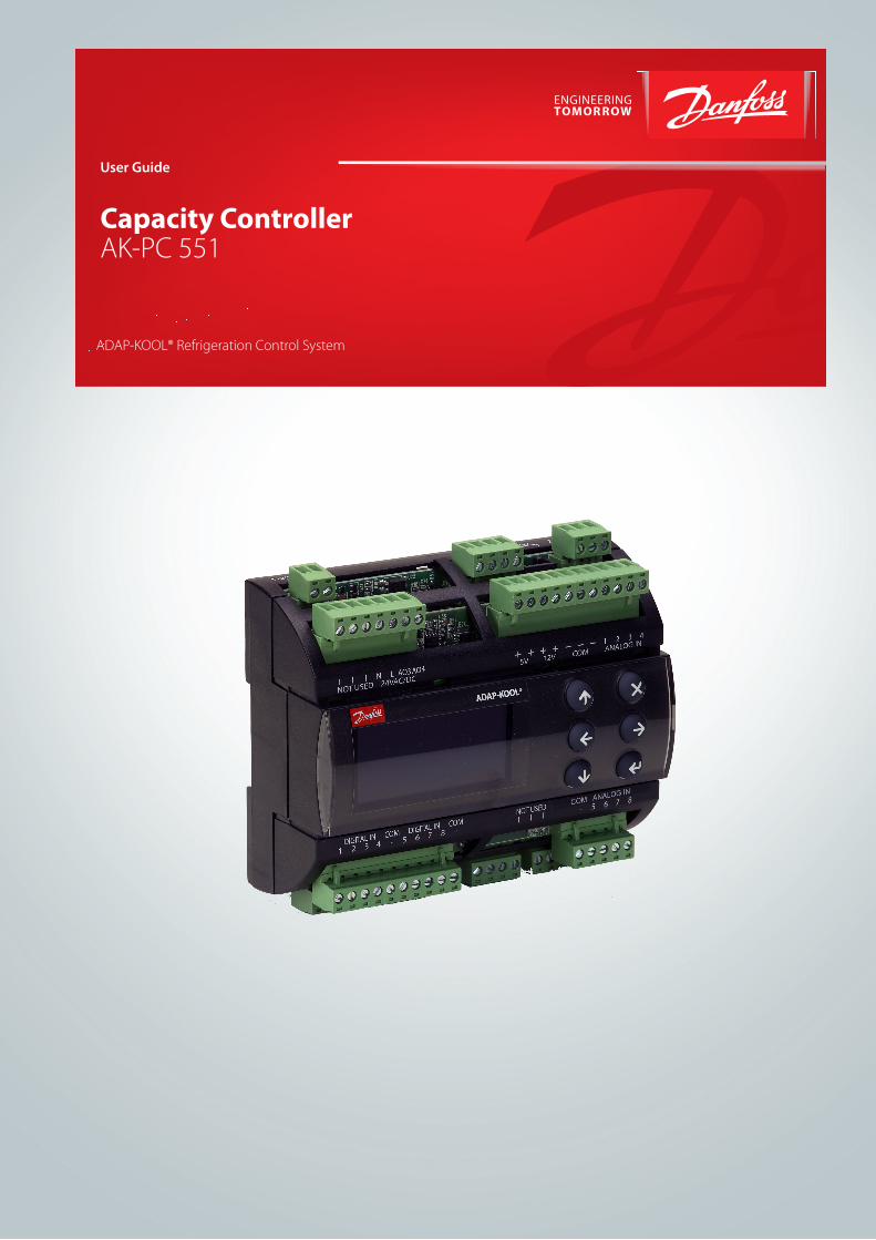
Capacity Controller AK-PC 551
User Guide
ADAP-KOOL® Refrigeration Control System
2 User Guide RS8GY402 © Danfoss 2016-11 AK-PC 551
Introduction
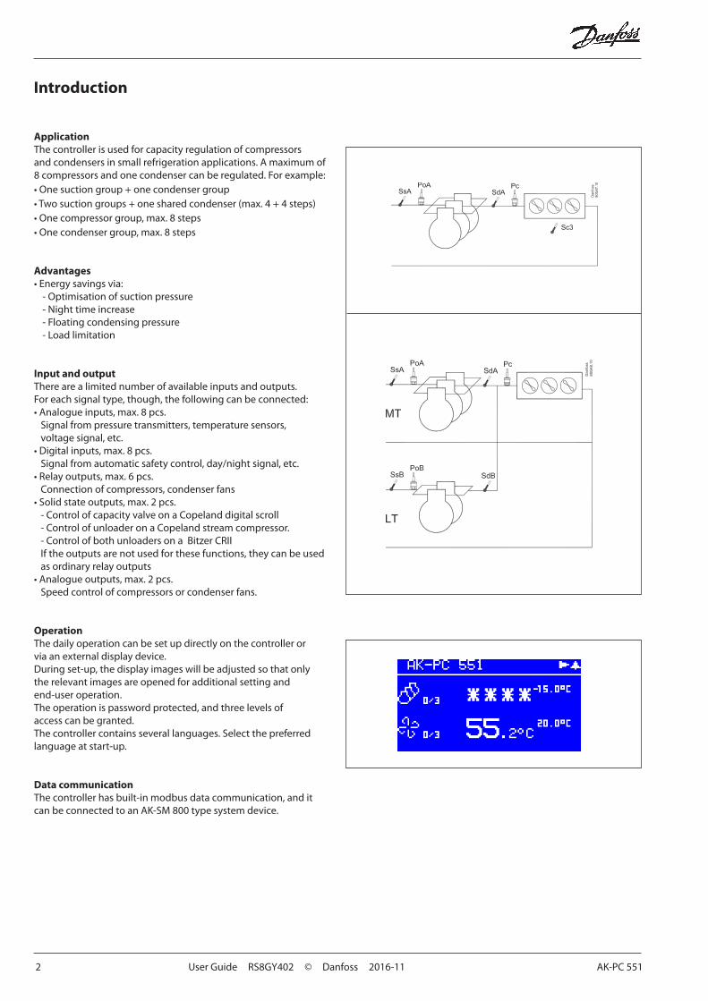
ApplicationThe controller is used for capacity regulation of compressors and condensers in small refrigeration applications. A maximum of 8 compressors and one condenser can be regulated. For example:• One suction group + one condenser group• Two suction groups + one shared condenser (max. 4 + 4 steps)• One compressor group, max. 8 steps• One condenser group, max. 8 steps
Advantages• Energy savings via:
- Optimisation of suction pressure- Night time increase- Floating condensing pressure- Load limitation
Input and outputThere are a limited number of available inputs and outputs. For each signal type, though, the following can be connected:• Analogue inputs, max. 8 pcs.
Signal from pressure transmitters, temperature sensors, voltage signal, etc.
• Digital inputs, max. 8 pcs.Signal from automatic safety control, day/night signal, etc.
• Relay outputs, max. 6 pcs.Connection of compressors, condenser fans
• Solid state outputs, max. 2 pcs.- Control of capacity valve on a Copeland digital scroll - Control of unloader on a Copeland stream compressor. - Control of both unloaders on a Bitzer CRIIIf the outputs are not used for these functions, they can be used as ordinary relay outputs
• Analogue outputs, max. 2 pcs.Speed control of compressors or condenser fans.
OperationThe daily operation can be set up directly on the controller or via an external display device.During set-up, the display images will be adjusted so that only the relevant images are opened for additional setting and end-user operation.The operation is password protected, and three levels of access can be granted. The controller contains several languages. Select the preferred language at start-up.
Data communicationThe controller has built-in modbus data communication, and it can be connected to an AK-SM 800 type system device.
AK-PC 551 User Guide RS8GY402 © Danfoss 2016-11 3
Suction Group
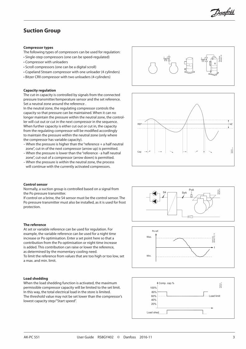
Compressor typesThe following types of compressors can be used for regulation:• Single-step compressors (one can be speed-regulated)• Compressor with unloaders• Scroll compressors (one can be a digital scroll)• Copeland Stream compressor with one unloader (4 cylinders)• Bitzer CRII compressor with two unloaders (4-cylinders)
Capacity regulationThe cut-in capacity is controlled by signals from the connected pressure transmitter/temperature sensor and the set reference.Set a neutral zone around the reference .In the neutral zone, the regulating compressor controls the capacity so that pressure can be maintained. When it can no longer maintain the pressure within the neutral zone, the control-ler will cut out or cut in the next compressor in the sequence. When further capacity is either cut out or cut in, the capacity from the regulating compressor will be modified accordingly to maintain the pressure within the neutral zone (only where the compressor has variable capacity).– When the pressure is higher than the “reference + a half neutral
zone”, cut-in of the next compressor (arrow up) is permitted.– When the pressure is lower than the “reference - a half neutral
zone”, cut-out of a compressor (arrow down) is permitted.– When the pressure is within the neutral zone, the process
will continue with the currently activated compressors.
Control sensorNormally, a suction group is controlled based on a signal from the Po pressure transmitter. If control on a brine, the S4 sensor must be the control sensor. The Po pressure transmitter must also be installed, as it is used for frost protection.
The referenceAt set or variable reference can be used for regulation. For example, the variable reference can be used for a night time increase or Po optimisation. Enter a set point here so that a contribution from the Po optimisation or night time increase is added. This contribution can raise or lower the reference, as determined by the momentary cooling need. To limit the reference from values that are too high or too low, set a max. and min. limit.
Load sheddingWhen the load shedding function is activated, the maximum permissible compressor capacity will be limited to the set limit. In this way, the total electrical load in the store is limited.The threshold value may not be set lower than the compressor’s lowest capacity step/”Start speed”.
Min.
Max.
Po ref.
4 User Guide RS8GY402 © Danfoss 2016-11 AK-PC 551
Condenser
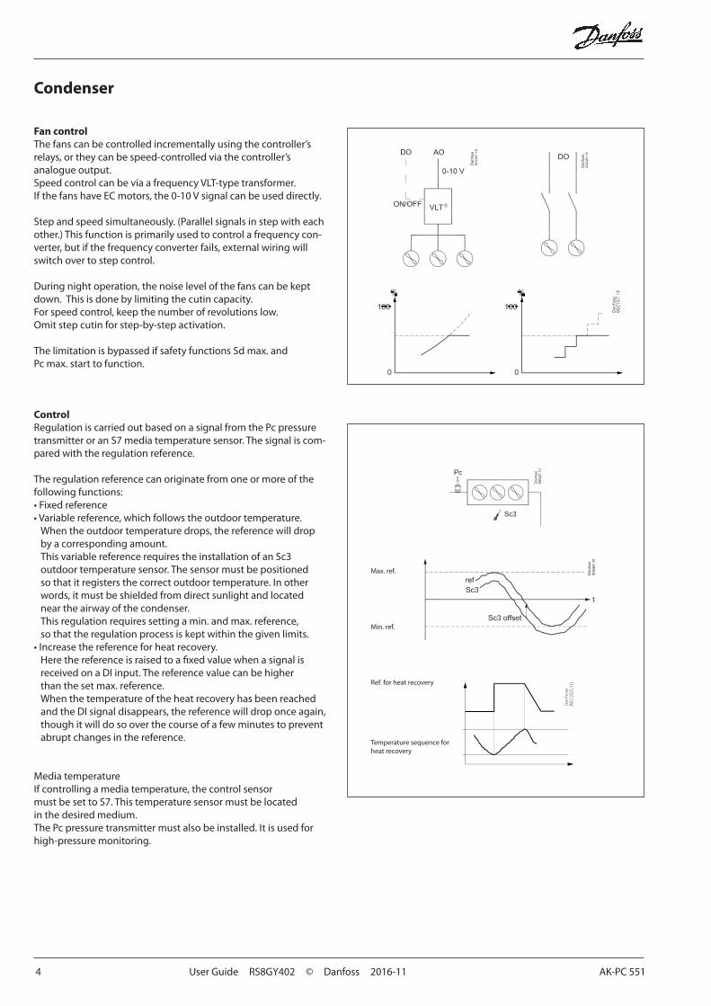
Fan controlThe fans can be controlled incrementally using the controller’s relays, or they can be speed-controlled via the controller’s analogue output.Speed control can be via a frequency VLT-type transformer.If the fans have EC motors, the 0-10 V signal can be used directly.
Step and speed simultaneously. (Parallel signals in step with each other.) This function is primarily used to control a frequency con-verter, but if the frequency converter fails, external wiring will switch over to step control.
During night operation, the noise level of the fans can be kept down. This is done by limiting the cutin capacity.For speed control, keep the number of revolutions low.Omit step cutin for step-by-step activation.
The limitation is bypassed if safety functions Sd max. and Pc max. start to function.
ControlRegulation is carried out based on a signal from the Pc pressure transmitter or an S7 media temperature sensor. The signal is com-pared with the regulation reference.
The regulation reference can originate from one or more of the following functions:• Fixed reference • Variable reference, which follows the outdoor temperature.
When the outdoor temperature drops, the reference will drop by a corresponding amount.This variable reference requires the installation of an Sc3 outdoor temperature sensor. The sensor must be positioned so that it registers the correct outdoor temperature. In other words, it must be shielded from direct sunlight and located near the airway of the condenser.This regulation requires setting a min. and max. reference, so that the regulation process is kept within the given limits.
• Increase the reference for heat recovery.Here the reference is raised to a fixed value when a signal is received on a DI input. The reference value can be higher than the set max. reference.When the temperature of the heat recovery has been reached and the DI signal disappears, the reference will drop once again, though it will do so over the course of a few minutes to prevent abrupt changes in the reference.
Media temperatureIf controlling a media temperature, the control sensor must be set to S7. This temperature sensor must be located in the desired medium.The Pc pressure transmitter must also be installed. It is used for high-pressure monitoring.
Min. ref.
Max. ref.
Ref. for heat recovery
Temperature sequence for heat recovery
AK-PC 551 User Guide RS8GY402 © Danfoss 2016-11 5
Safety functions
Min./max. suction pressure PoThe suction pressure is recorded continuously. If the measured value falls below the set minimum limit, the compressors will immediately cut out.If it exceeds the max. value, an alarm will be generated once the time delay has elapsed.
Max. condensing pressure PcIf the condensing pressure reaches the upper permissible value, the controller will connect all condenser fans to keep the pressure down. At the same time, a portion of the compressor capacity will be disconnected. If the pressure remains near the threshold value, even more compressors will be disconnected.All compressors will be disconnected immediately if the threshold value is exceeded.
LP switchOn/off signal on a DI inputIf a signal is received, all compressors will immediately be stopped.
HP switchOn/off signal on a DI inputIf a signal is received, all compressors will immediately be stopped. Fan capacity will increase depending on how much the Pc measurement exceeds the reference.
Min./max superheating via Ss measurementTemperature sensor on an AI input.If superheating is higher or lower than the set limits, an alarm will be generated once the time delay has elapsed.
Max. discharge gas temperature SdTemperature sensor on an AI input.A signal can be received from a Pt 1000 Ohm sensor on the pressure pipe.• Common Sd for the whole compressor group
If the temperature nears the set max. temperature, the capacity of the compressor will be reduced
• Compressor Sdif it is an Sd from a Copeland digital scroll, a Copeland stream or Bitzer CRII the capacity will be increased so that the compressor can cool down itself ).
The compressors will be stopped if the temperature nears the set max. temperature value.
Sensor failureIf lack of signal from one of the connected temperature sensors orpressure transmitters is registered an alarm will be given. • In the event of a Po error, regulation will continue with a set
capacity in daytime operation (e.g. 50%), and a set capacity in night operation (e.g. 25%), but with a minimum of one step.
• In the event of a Pc error, the condenser capacity that corresponds to how much compressor capacity is connected will cut in. Compressor regulation will remain normal.
• When there is an error on the Sd sensor the safety monitoring of the discharge gas temperature will be discontinued.
• When there is an error on the Ss sensor the monitoring of the superheat on the suction line will be discontinued.
• In the event of an error on the outdoor temperature sensor, Sc3, the permanent setting value will be used as a reference.
• In the event of an error on the S4 sensor, regulation will continue with the Po signal, but the reference will be lowered by 5 K.
• In the event of an error on the Saux sensor, the thermostat output will go to the rest position.
NB: A faulty sensor must be OK within 10 minutes before a sensor alarm is cancelled.
A sensor alarm can be reset manually by pushing the "X-button" for 2 seconds when the alarm is shown in the display "Active alarms".
General DI alarmsOn/off signal on a DI inputThe regulator contains three general alarm inputs, to which alarm text and delay times can be connected. Alarm and text will appear when the delay time has elapsed.
General thermostatIt is possible to install one general thermostat if there is a relay output and an analogue input available.
6 User Guide RS8GY402 © Danfoss 2016-11 AK-PC 551
Display overview
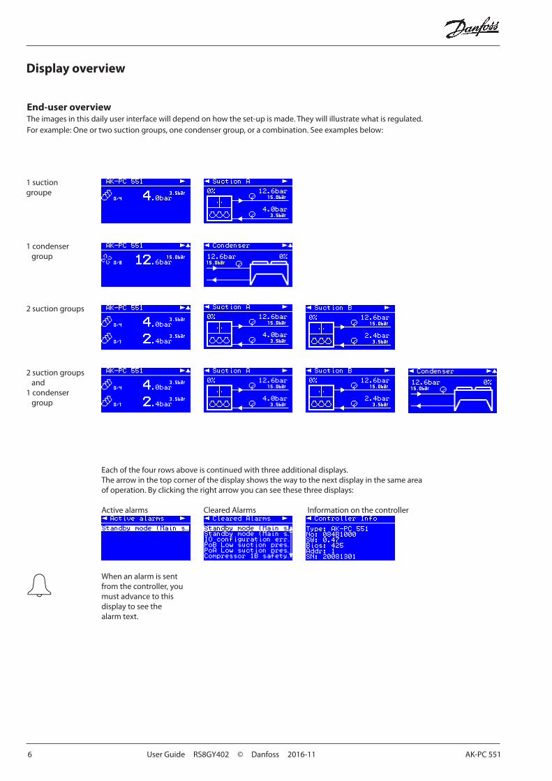
End-user overview The images in this daily user interface will depend on how the set-up is made. They will illustrate what is regulated. For example: One or two suction groups, one condenser group, or a combination. See examples below:
1 condenser group
1 suction groupe
2 suction groups
2 suction groups and
1 condenser group
Each of the four rows above is continued with three additional displays. The arrow in the top corner of the display shows the way to the next display in the same area of operation. By clicking the right arrow you can see these three displays:
Active alarms Cleared Alarms Information on the controller
When an alarm is sent from the controller, you must advance to this display to see the alarm text.
AK-PC 551 User Guide RS8GY402 © Danfoss 2016-11 7
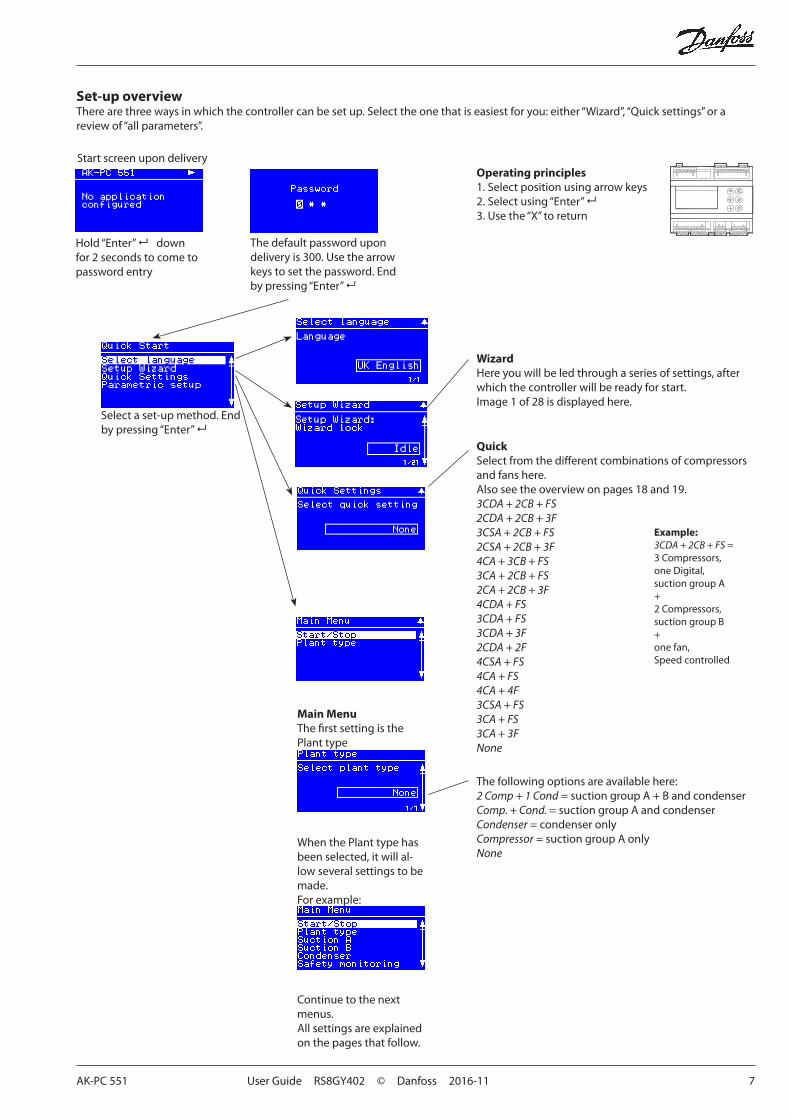
WizardHere you will be led through a series of settings, after which the controller will be ready for start.Image 1 of 28 is displayed here.
QuickSelect from the different combinations of compressors and fans here.Also see the overview on pages 18 and 19.3CDA + 2CB + FS2CDA + 2CB + 3F3CSA + 2CB + FS2CSA + 2CB + 3F4CA + 3CB + FS3CA + 2CB + FS2CA + 2CB + 3F4CDA + FS3CDA + FS3CDA + 3F2CDA + 2F4CSA + FS4CA + FS4CA + 4F3CSA + FS3CA + FS 3CA + 3FNone
The following options are available here:2 Comp + 1 Cond = suction group A + B and condenserComp. + Cond. = suction group A and condenserCondenser = condenser onlyCompressor = suction group A onlyNone
Main MenuThe first setting is the Plant type
When the Plant type has been selected, it will al-low several settings to be made.For example:
Continue to the next menus.All settings are explained on the pages that follow.
Start screen upon delivery
Set-up overviewThere are three ways in which the controller can be set up. Select the one that is easiest for you: either “Wizard”, “Quick settings” or a review of “all parameters”.
The default password upon delivery is 300. Use the arrow keys to set the password. End by pressing “Enter”
Hold “Enter” down for 2 seconds to come to password entry
Select a set-up method. End by pressing “Enter”
Operating principles1. Select position using arrow keys2. Select using “Enter” 3. Use the “X” to return
Example:3CDA + 2CB + FS = 3 Compressors, one Digital, suction group A + 2 Compressors, suction group B + one fan, Speed controlled
8 User Guide RS8GY402 © Danfoss 2016-11 AK-PC 551
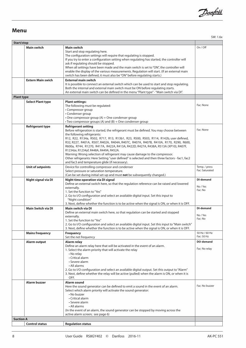
Start/stop
Main switch Main switchStart and stop regulating here.The configuration settings will require that regulating is stopped. If you try to enter a configuration setting when regulating has started, the controller will ask if regulating should be stopped.When all settings have been made and the main switch is set to “ON”, the controller will enable the display of the various measurements. Regulation will start. (If an external main switch has been defined, it must also be “ON” before regulating starts.)
On / Off
Extern Main swich External main switchIt is possible to connect an external switch which can be used to start and stop regulating.Both the internal and external main switch must be ON before regulating starts. An external main switch can be defined in the menu “Plant type” - “Main switch via DI”.
Plant type
Select Plant type Plant settings:The following must be regulated:• Compressor group• Condenser group• One compressor group (A) + One condenser group• Two compressor groups (A) and (B) + One condenser group
Fac: None
Refrigerant type Refrigerant settingBefore refrigeration is started, the refrigerant must be defined. You may choose between the following refrigerants:R12, R22, R134a, R502, R717, R13, R13b1, R23, R500, R503, R114, R142b, user defined, R32, R227, R401A, R507, R402A, R404A, R407C, R407A, R407B, R410A, R170, R290, R600, R600a, R744, R1270, R417A, R422A, R413A, R422D, R427A, R438A, R513A (XP10), R407F, R1234ze, R1234yf, R448A, R449A, R452A.Warning: Wrong selection of refrigerant may cause damage to the compressor.Other refrigerants: Here Setting "user defined" is selected and then three factors - fac1, fac2 and fac3 and temperature glide (if necessary).
Fac: None
Unit of setpoints Device for controlling compressor and condenserSelect pressure or saturation temperature.(Can be set during initial set-up and must not be subsequently changed.)
Temp. / pressFac: Saturated
Night signal via DI Night time operation via DI signalDefine an external switch here, so that the regulation reference can be raised and lowered externally. 1. Set the function to “Yes”2. Go to I/O configuration and select an available digital input. Set this input to
“Night condition”3. Next, define whether the function is to be active when the signal is ON, or when it is OFF.
DI-demand
No / YesFac: No
Main Switch via DI Main switch via DIDefine an external main switch here, so that regulation can be started and stopped externally.1. Set the function to “Yes”2. Go to I/O configuration and select an available digital input. Set this input to “Main switch”3. Next, define whether the function is to be active when the signal is ON, or when it is OFF.
DI-demand
No / YesFac: No
Mains frequency FrequencySet the net frequency
50 Hz / 60 HzFac: 50 Hz
Alarm output Alarm relayDefine an alarm relay here that will be activated in the event of an alarm.1. Select the alarm priority that will activate the relay
• No relay• Critical alarm• Severe alarm• All alarms
2. Go to I/O configuration and select an available digital output. Set this output to “Alarm”3. Next, define whether the relay will be active (pulled) when the alarm is ON, or when it is
OFF.
DO-demand
Fac: No relay
Alarm buzzer Alarm soundHere the sound generator can be defined to emit a sound in the event of an alarm.Select which alarm priority will activate the sound generator:
• No buzzer• Critical alarm• Severe alarm• All alarms
(In the event of an alarm, the sound generator can be stopped by moving across the active alarm screen; see page 6)
Fac: No buzzer
Suction A
Control status Regulation status
MenuSW: 1.6x
AK-PC 551 User Guide RS8GY402 © Danfoss 2016-11 9
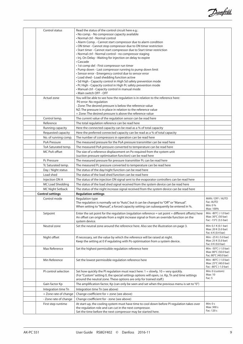
Control status Read the status of the control circuit here e.g.:• No comp. - No compressor capacity available• Normal ctrl - Normal control• Alarm Comp. - Cannot start compressor due to alarm condition• ON timer - Cannot stop compressor due to ON timer restriction• Start timer - Cannot start compressor due to Start timer restriction• Normal ctrl - Normal control - no compressor staging• Inj. On Delay - Waiting for injection on delay to expire• Cascade • 1st comp del - First compressor run timer• Pump down - Last compressor running to pump down limit• Sensor error - Emergency control due to sensor error• Load shed - Load shedding function active• Sd High - Capacity control in High Sd safety prevention mode• Pc High - Capacity control in High Pc safety prevention mode• Manual ctrl - Capacity control in manual mode• Main switch OFF - OFF
Actuel zone You will be able to see how the regulation is in relation to the reference here: P0 error: No regulation- Zone: The desired pressure is below the reference valueNZ: The pressure is in place in relation to the reference value+ Zone: The desired pressure is above the reference value
Control temp. The current value of the regulation sensor can be read here
Reference The total regulation reference can be read here
Running capacity Here the connected capacity can be read as a % of total capacity
Requested capacity Here the preferred connected capacity can be read as a % of total capacity
No. of running comp. The number of compressors in operation can be read here
PoA Pressure The measured pressure for the PoA pressure transmitter can be read here
ToA Saturated temp. The measured PoA pressure converted to temperature can be read here
MC PoA offset The size of a reference displacement on Po required from the system unit (suction pressure optimisation function) can be read here
Pc Pressure The measured pressure for pressure transmitter Pc can be read here
Tc Saturated temp. The measured Pc pressure converted to temperature can be read here
Day / Night status The status of the day/night function can be read here
Load shed The status of the load shed function can be read here
Injection ON A The status of the injection ON signal sent to the evaporator controllers can be read here
MC Load Shedding The status of the load shed signal received from the system device can be read here
MC Night Setback The status of the night increase signal received from the system device can be read here
Control settings Regulation settings
Control mode Regulation typeThe regulation is normally set to “Auto”, but it can be changed to “Off” or “Manual”. When setting to “Manual”, a forced capacity setting can subsequently be entered in %.
MAN / OFF / AUTOFac: AUTOMin: 0 %Max: 100%
Setpoint Enter the set point for the regulation (regulation reference = set point + different offsets) hereAn offset can originate from a night increase signal or from an override function on the system device.
Min: -80°C (-1.0 bar)Max: 30°C (50 bar)Fac: -15°C (3.5 bar)
Neutral zone Set the neutral zone around the reference here. Also see the illustration on page 3. Min: 0,1 K (0.1 bar)Max: 20 K (5.0 bar)Fac: 6 K (0.4 bar)
Night offset If necessary, set the value by which the reference will be raised at night. Keep the setting at 0 if regulating with Po optimisation from a system device.
Min: -25 K (-5.0 bar)Max: 25 K (5.0 bar)Fac: 0 K (0.0 bar)
Max Reference Set the highest permissible regulation reference here Min: -50°C (-1.0 bar)Max: 80°C (50.0 bar)Fac: 80°C (40.0 bar)
Min Reference Set the lowest permissible regulation reference here Min: -80°C (-1.0 bar)Max: 25°C (40.0 bar)Fac: -80°C (-1.0 bar)
PI control selection Set how quickly the PI regulation must react here: 1 = slowly, 10 = very quickly.(For “Custom” setting 0, the special settings options will open, i.e. Kp, Tn and time settings around the neutral zone. These options are only for trained staff.)
Min: 0 (custom)Max: 10Fac: 5
Gain factor Kp The amplification factor, Kp (can only be seen and set when the previous menu is set to “0”)
Integration time Tn Integration time Tn (see above)
+ Zone rate of change Change coefficient for + zone (see above)
- Zone rate of change Change coefficient for - zone (see above)
First step runtime At start-up, the cooling system must have time to cool down before PI regulation takes over the regulation role and can cut in the next compressor.Set the time before the next compressor may be started here.
Min: 0 sMax: 300 sFac: 120 s
10 User Guide RS8GY402 © Danfoss 2016-11 AK-PC 551
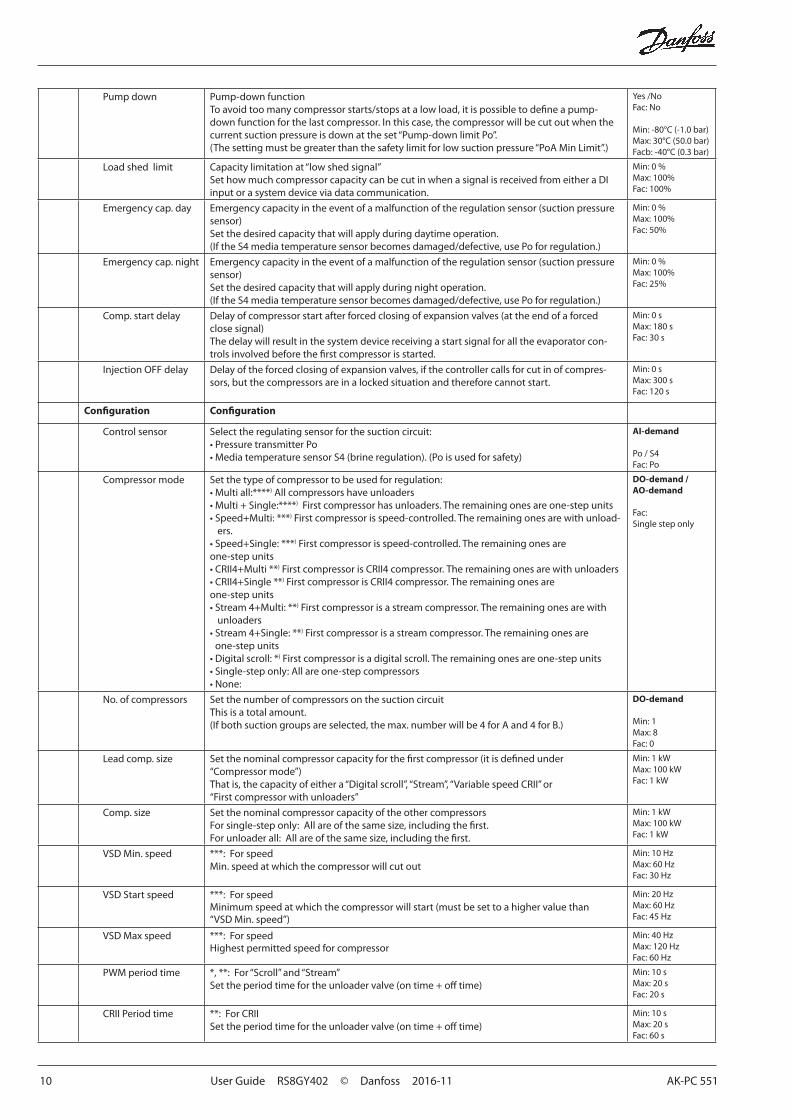
Pump down Pump-down functionTo avoid too many compressor starts/stops at a low load, it is possible to define a pump-down function for the last compressor. In this case, the compressor will be cut out when the current suction pressure is down at the set “Pump-down limit Po”.(The setting must be greater than the safety limit for low suction pressure “PoA Min Limit”.)
Yes /NoFac: No
Min: -80°C (-1.0 bar)Max: 30°C (50.0 bar)Facb: -40°C (0.3 bar)
Load shed limit Capacity limitation at “low shed signal”Set how much compressor capacity can be cut in when a signal is received from either a DI input or a system device via data communication.
Min: 0 %Max: 100%Fac: 100%
Emergency cap. day Emergency capacity in the event of a malfunction of the regulation sensor (suction pressure sensor)Set the desired capacity that will apply during daytime operation.(If the S4 media temperature sensor becomes damaged/defective, use Po for regulation.)
Min: 0 %Max: 100%Fac: 50%
Emergency cap. night Emergency capacity in the event of a malfunction of the regulation sensor (suction pressure sensor)Set the desired capacity that will apply during night operation.(If the S4 media temperature sensor becomes damaged/defective, use Po for regulation.)
Min: 0 %Max: 100%Fac: 25%
Comp. start delay Delay of compressor start after forced closing of expansion valves (at the end of a forced close signal)The delay will result in the system device receiving a start signal for all the evaporator con-trols involved before the first compressor is started.
Min: 0 sMax: 180 sFac: 30 s
Injection OFF delay Delay of the forced closing of expansion valves, if the controller calls for cut in of compres-sors, but the compressors are in a locked situation and therefore cannot start.
Min: 0 sMax: 300 sFac: 120 s
Configuration Configuration
Control sensor Select the regulating sensor for the suction circuit:• Pressure transmitter Po • Media temperature sensor S4 (brine regulation). (Po is used for safety)
AI-demand
Po / S4Fac: Po
Compressor mode Set the type of compressor to be used for regulation:• Multi all:****) All compressors have unloaders• Multi + Single:****) First compressor has unloaders. The remaining ones are one-step units• Speed+Multi: ***) First compressor is speed-controlled. The remaining ones are with unload-
ers.• Speed+Single: ***) First compressor is speed-controlled. The remaining ones are one-step units• CRII4+Multi **) First compressor is CRII4 compressor. The remaining ones are with unloaders• CRII4+Single **) First compressor is CRII4 compressor. The remaining ones are one-step units• Stream 4+Multi: **) First compressor is a stream compressor. The remaining ones are with
unloaders• Stream 4+Single: **) First compressor is a stream compressor. The remaining ones are
one-step units• Digital scroll: *) First compressor is a digital scroll. The remaining ones are one-step units• Single-step only: All are one-step compressors• None:
DO-demand /AO-demand
Fac: Single step only
No. of compressors Set the number of compressors on the suction circuitThis is a total amount.(If both suction groups are selected, the max. number will be 4 for A and 4 for B.)
DO-demand
Min: 1Max: 8 Fac: 0
Lead comp. size Set the nominal compressor capacity for the first compressor (it is defined under “Compressor mode”)That is, the capacity of either a “Digital scroll”, “Stream”, “Variable speed CRII” or “First compressor with unloaders”
Min: 1 kWMax: 100 kWFac: 1 kW
Comp. size Set the nominal compressor capacity of the other compressorsFor single-step only: All are of the same size, including the first.For unloader all: All are of the same size, including the first.
Min: 1 kWMax: 100 kWFac: 1 kW
VSD Min. speed ***: For speedMin. speed at which the compressor will cut out
Min: 10 HzMax: 60 HzFac: 30 Hz
VSD Start speed ***: For speedMinimum speed at which the compressor will start (must be set to a higher value than “VSD Min. speed”)
Min: 20 HzMax: 60 HzFac: 45 Hz
VSD Max speed ***: For speedHighest permitted speed for compressor
Min: 40 HzMax: 120 HzFac: 60 Hz
PWM period time *, **: For “Scroll” and “Stream”Set the period time for the unloader valve (on time + off time)
Min: 10 sMax: 20 sFac: 20 s
CRII Period time **: For CRIISet the period time for the unloader valve (on time + off time)
Min: 10 sMax: 20 sFac: 60 s
AK-PC 551 User Guide RS8GY402 © Danfoss 2016-11 11
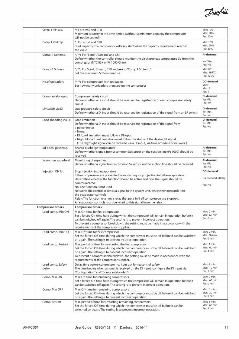
Comp. 1 min cap. *: For scroll and CRIIMinimum capacity in the time period (without a minimum capacity the compressor will not be cooled)
Min: 10%Max: 50%Fac: 10%
Comp. 1 start cap *: For scroll and CRIIStart capacity: the compressor will only start when the capacity requirement reaches the value
Min: 10%Max: 60%Fac: 30%
Comp. 1 Sd temp. *, **: For “Scroll”, “Stream” and CRIIDefine whether the controller should monitor the discharge gas temperature Sd from the compressor (NTC 86K or Pt 1000 Ohm).
AI-demand
No / YesFac: No
Comp. 1 Sd max. *, **: For Scroll, Stream, CRII and yes to “Comp.1 Sd temp”Set the maximum Sd temperature
Min: 0°CMax: 195°CFac: 125°C
No.of unloaders ****: For compressor with unloadersSet how many unloaders there are on the compressor
DO-demandMin: 1Max: 3 Fac: 1
Comp. safety input Compressor safety circuitDefine whether a DI input should be reserved for registration of each compressor safety circuit
DI-demandYes /NoFac: Yes
LP switch via DI Low pressure safety circuitDefine whether a DI input should be reserved for registration of the signal from an LP switch
DI-demandYes /NoFac: No
Load shedding via DI Load limitationDefine whether a DI input should be reserved for registration of the signal from a power meter• None:• DI: Load limitation must follow a DI input• Night Mode: Load limitation must follow the status of the day/night signal.
(The day/night signal can be received via a DI input, via time schedule or network.)
DI-demandYes /NoFac: No
Sd disch. gas temp. Shared discharge temperatureDefine whether signals from a common Sd sensor on the suction line (Pt 1000) should be received
AI-demandYes /NoFac: No
Ss suction superheat Monitoring of superheatDefine whether a signal from a common Ss sensor on the suction line should be received
AI-demandYes /NoFac: No
Injection ON fct. Stop injection into evaporatorsIf the compressors are prevented from starting, stop injection into the evaporators.Here define whether the function should be active and how the signal should be communicated.No: The function is not usedNetwork: The controller sends a signal to the system unit, which then forwards it to the evaporator controlsRelay: The function reserves a relay that pulls in if all compressors are stopped. All evaporator controls must be wired to this signal from the relay.
DO-demand
No /Network /Relay
Fac: No
Compressor timers Compressor timers
Lead comp. Min ON Min. On-time for first compressorSet a forced On-time here during which the compressor will remain in operation before it can be switched off again. The setting is to prevent incorrect operation. To prevent a compressor breakdown, the setting must be made in accordance with the requirements of the compressor supplier.
Min: 0 minMax: 60 minFac: 0 min
Lead comp. Min OFF Min. Off-time for first compressorSet the forced Off-time during which the compressor must be off before it can be switched on again. The setting is to prevent incorrect operation.
Min: 0 min.Max: 30 minFac: 0 min
Lead comp. Restart Min. period of time for re-starting the first compressor. Set the forced Off-time during which the compressor must be off before it can be switched on again. The setting is to prevent incorrect operation.To prevent a compressor breakdown, the setting must be made in accordance with the requirements of the compressor supplier.
Min: 1 min.Max: 60 minFac: 4 min
Lead comp. Safety delay
Delay time before compressor no. 1 cut out for reasons of safetyThe time begins when a signal is received on the DI input (configure the DI input via “Configuration” and “Comp. safety inlet”).
Min: 1 min.Max: 10 minFac: 1 min
Comp. Min ON Min. On-time for remaining compressorsSet a forced On-time here during which the compressor will remain in operation before it can be switched off again. The setting is to prevent incorrect operation.
Min: 0 min.Max: 60 minFac: 0 min
Comp. Min OFF Min. Off-time for remaining compressorsSet the forced Off-time during which the compressor must be off before it can be switched on again. The setting is to prevent incorrect operation.
Min: 0 min.Max: 30 minFac: 0 min
Comp. Restart Min. period of time for restarting remaining compressors Set the forced Off-time during which the compressor must be off before it can be switched on again. The setting is to prevent incorrect operation.
Min: 1 min.Max: 60 minFac: 4 min
12 User Guide RS8GY402 © Danfoss 2016-11 AK-PC 551
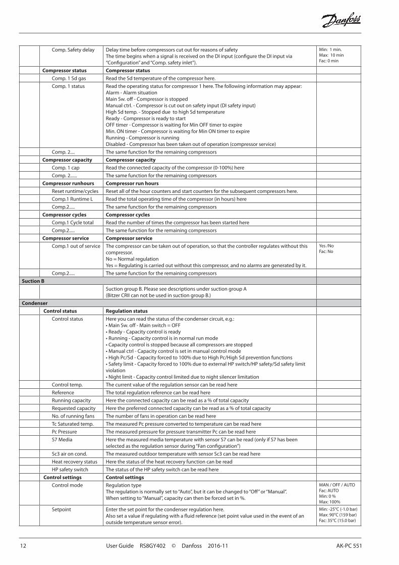
Comp. Safety delay Delay time before compressors cut out for reasons of safetyThe time begins when a signal is received on the DI input (configure the DI input via “Configuration” and “Comp. safety inlet”).
Min: 1 min.Max: 10 minFac: 0 min
Compressor status Compressor status
Comp. 1 Sd gas Read the Sd temperature of the compressor here.
Comp. 1 status Read the operating status for compressor 1 here. The following information may appear:Alarm - Alarm situationMain Sw. off - Compressor is stoppedManual ctrl. - Compressor is cut out on safety input (DI safety input)High Sd temp. - Stopped due to high Sd temperatureReady - Compressor is ready to startOFF timer - Compressor is waiting for Min OFF timer to expireMin. ON timer - Compressor is waiting for Min ON timer to expireRunning - Compressor is runningDisabled - Compressor has been taken out of operation (compressor service)
Comp. 2.... The same function for the remaining compressors
Compressor capacity Compressor capacity
Comp. 1 cap Read the connected capacity of the compressor (0-100%) here
Comp. 2...... The same function for the remaining compressors
Compressor runhours Compressor run hours
Reset runtime/cycles Reset all of the hour counters and start counters for the subsequent compressors here.
Comp.1 Runtime L Read the total operating time of the compressor (in hours) here
Comp.2..... The same function for the remaining compressors
Compressor cycles Compressor cycles
Comp.1 Cycle total Read the number of times the compressor has been started here
Comp.2..... The same function for the remaining compressors
Compressor service Compressor service
Comp.1 out of service The compressor can be taken out of operation, so that the controller regulates without this compressor.No = Normal regulationYes = Regulating is carried out without this compressor, and no alarms are generated by it.
Yes /NoFac: No
Comp.2..... The same function for the remaining compressors
Suction B
Suction group B. Please see descriptions under suction group A (Bitzer CRII can not be used in suction group B.)
Condenser
Control status Regulation status
Control status Here you can read the status of the condenser circuit, e.g.:• Main Sw. off - Main switch = OFF• Ready - Capacity control is ready• Running - Capacity control is in normal run mode• Capacity control is stopped because all compressors are stopped• Manual ctrl - Capacity control is set in manual control mode• High Pc/Sd - Capacity forced to 100% due to High Pc/High Sd prevention functions• Safety limit - Capacity forced to 100% due to external HP switch/HP safety/Sd safety limit violation• Night limit - Capacity control limited due to night silencer limitation
Control temp. The current value of the regulation sensor can be read here
Reference The total regulation reference can be read here
Running capacity Here the connected capacity can be read as a % of total capacity
Requested capacity Here the preferred connected capacity can be read as a % of total capacity
No. of running fans The number of fans in operation can be read here
Tc Saturated temp. The measured Pc pressure converted to temperature can be read here
Pc Pressure The measured pressure for pressure transmitter Pc can be read here
S7 Media Here the measured media temperature with sensor S7 can be read (only if S7 has been selected as the regulation sensor during “Fan configuration”)
Sc3 air on cond. The measured outdoor temperature with sensor Sc3 can be read here
Heat recovery status Here the status of the heat recovery function can be read
HP safety switch The status of the HP safety switch can be read here
Control settings Control settings
Control mode Regulation typeThe regulation is normally set to “Auto”, but it can be changed to “Off” or “Manual”. When setting to “Manual”, capacity can then be forced set in %.
MAN / OFF / AUTOFac: AUTOMin: 0 %Max: 100%
Setpoint Enter the set point for the condenser regulation here. Also set a value if regulating with a fluid reference (set point value used in the event of an outside temperature sensor error).
Min: -25°C (-1.0 bar)Max: 90°C (159 bar)Fac: 35°C (15.0 bar)
AK-PC 551 User Guide RS8GY402 © Danfoss 2016-11 13
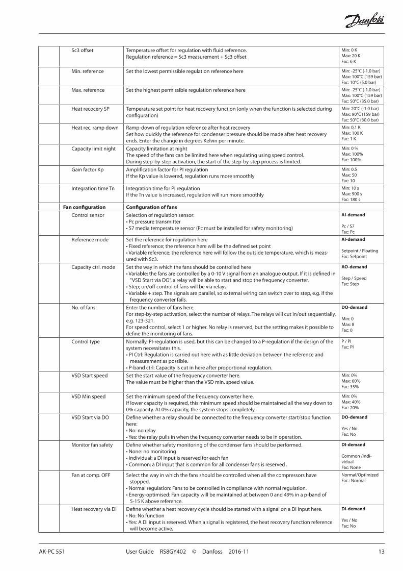
Sc3 offset Temperature offset for regulation with fluid reference.Regulation reference = Sc3 measurement + Sc3 offset
Min: 0 KMax: 20 KFac: 6 K
Min. reference Set the lowest permissible regulation reference here Min: -25°C (-1.0 bar)Max: 100°C (159 bar)Fac: 10°C (5.0 bar)
Max. reference Set the highest permissible regulation reference here Min: -25°C (-1.0 bar)Max: 100°C (159 bar)Fac: 50°C (35.0 bar)
Heat recocery SP Temperature set point for heat recovery function (only when the function is selected during configuration)
Min: 20°C (-1.0 bar)Max: 90°C (159 bar)Fac: 50°C (30.0 bar)
Heat rec. ramp down Ramp-down of regulation reference after heat recoverySet how quickly the reference for condenser pressure should be made after heat recovery ends. Enter the change in degrees Kelvin per minute.
Min: 0,1 KMax: 100 KFac: 1 K
Capacity limit night Capacity limitation at nightThe speed of the fans can be limited here when regulating using speed control.During step-by-step activation, the start of the step-by-step process is limited.
Min: 0 %Max: 100%Fac: 100%
Gain factor Kp Amplification factor for PI regulationIf the Kp value is lowered, regulation runs more smoothly
Min: 0.5Max: 50 Fac: 10
Integration time Tn Integration time for PI regulationIf the Tn value is increased, regulation will run more smoothly
Min: 10 sMax: 900 sFac: 180 s
Fan configuration Configuration of fans
Control sensor Selection of regulation sensor:• Pc pressure transmitter• S7 media temperature sensor (Pc must be installed for safety monitoring)
AI-demand
Pc / S7Fac: Pc
Reference mode Set the reference for regulation here• Fixed reference; the reference here will be the defined set point• Variable reference; the reference here will follow the outside temperature, which is meas-ured with Sc3.
AI-demand
Setpoint / FloatingFac: Setpoint
Capacity ctrl. mode Set the way in which the fans should be controlled here• Variable; the fans are controlled by a 0-10 V signal from an analogue output. If it is defined in
“VSD Start via DO”, a relay will be able to start and stop the frequency converter.• Step; on/off control of fans will be via relays• Variable + step. The signals are parallel, so external wiring can switch over to step, e.g. if the
frequency converter fails.
AO-demand
Step / SpeedFac: Step
No. of fans Enter the number of fans here.For step-by-step activation, select the number of relays. The relays will cut in/out sequentially, e.g. 123-321.For speed control, select 1 or higher. No relay is reserved, but the setting makes it possible to define the monitoring of fans.
DO-demand
Min: 0Max: 8 Fac: 0
Control type Normally, PI-regulation is used, but this can be changed to a P-regulation if the design of the system necessitates this.• PI Ctrl: Regulation is carried out here with as little deviation between the reference and
measurement as possible. • P-band ctrl: Capacity is cut in here after proportional regulation.
P / PIFac: PI
VSD Start speed Set the start value of the frequency converter here. The value must be higher than the VSD min. speed value.
Min: 0%Max: 60% Fac: 35%
VSD Min speed Set the minimum speed of the frequency converter here.If lower capacity is required, this minimum speed should be maintained all the way down to 0% capacity. At 0% capacity, the system stops completely.
Min: 0%Max: 40% Fac: 20%
VSD Start via DO Define whether a relay should be connected to the frequency converter start/stop function here:• No: no relay• Yes: the relay pulls in when the frequency converter needs to be in operation.
DO-demand
Yes / NoFac: No
Monitor fan safety Define whether safety monitoring of the condenser fans should be performed.• None: no monitoring• Individual: a DI input is reserved for each fan• Common: a DI input that is common for all condenser fans is reserved .
DI-demand
Common /Indi-vidualFac: None
Fan at comp. OFF Select the way in which the fans should be controlled when all the compressors have stopped.
• Normal regulation: Fans to be controlled in compliance with normal regulation.• Energy-optimised: Fan capacity will be maintained at between 0 and 49% in a p-band of
5-15 K above reference.
Normal/OptimizedFac.: Normal
Heat recovery via DI Define whether a heat recovery cycle should be started with a signal on a DI input here.• No: No function• Yes: A DI input is reserved. When a signal is registered, the heat recovery function reference
will become active.
DI-demand
Yes / NoFac: No
14 User Guide RS8GY402 © Danfoss 2016-11 AK-PC 551
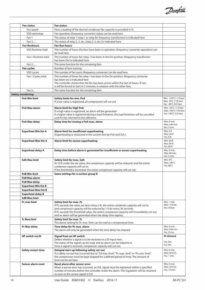
Fan status Fan status
Fan speed Here a reading of the desired condenser fan capacity is provided in %
VSD start/stop Fan operation (frequency converter) status can be read here
Fan 1 The status of relay 1 (step 1 or relay for frequency transformer) is indicated here
Fan 2..... The status of relay 2, 3, etc. (step 2, 3, etc.) is indicated here
Fan Runhours Fan Run hours
VSD Runtime total The number of hours the fans have been in operation (frequency converter operation) can be read here
Fan 1 Runtime total The number of hours fan relay 1 has been in the On-position (frequency transformer has been On) is indicated here
Fan 2..... The same function for the remaining fans
Fan cycles Number of fans starting
VSD cycles The number of fan starts (frequency converter) can be read here
Fan 1 Cycles total The number of times fan relay 1 has been in the On-position (frequency converter has been on) is indicated hereThe controller checks that the fan has been active within the last 24 hours. If not, it will be forced to start in 5 minutes, in rotation with the other fans.
Fan 2... The same function for the remaining fans
Safety monitoring
PoA Min limit Safety limits for min. PoAIf a low value is registered, all compressors will cut out
Min: -120°C (-1.0 bar)Max: 30°C (159 bar)Fac: -40°C (0.5 bar)
PoA Max alarm Alarm limit for high PoAIf a high value is registered, an alarm will be generated If a higher value is registered during a load limitation, the load limitation will be cancelled until Po has returned to the reference.
Min: -30°C (-1.0 bar)Max: 100°C (159 bar)Fac: 100°C (5.0 bar)
PoA Max delay Delay time for issuing a PoA max. alarm Min: 0 min.Max: 240 min.Fac: 5 min.
Superheat Min lim A Alarm limit for insufficient superheating(Superheating is measured in the suction line by PoA and SsA.)
Min: 0 KMax: 20 KFac: 0 K
Superheat Max lim A Alarm limit for excess superheating Min: 20 KMax: 80 KFac: 80 K
Superheat delay A Delay time before alarm is generated for insufficient or excess superheating Min: 0 min.Max: 60 min.Fac: 5 min.
SdA Max limit Safety limit for max. SdAAt 10 K under the set value, the compressor capacity will be reduced, and the entire condenser capacity will cut in.If the threshold is exceeded, the entire compressor capacity will cut out.
Min: 0°CMax: 195°CFac: 80°C
PoB Min limit Same settings for a suction group B
PoB Max alarm
PoB Max delay
Superheat Min lim B
Superheat Max lim B
Superheat delay B
SdB Max limit
Pc max limit Safety limit for max. PcIf Pc exceeds the value set here minus 3 K, the entire condenser capacity will cut in, and compressor capacity will be reduced by 1/3 for every 30 seconds.If Pc exceeds the threshold value, the entire compressor capacity will immediately cut out, and an alarm will be generated when the delay time expires.
Min: -1 barMax: 159 barFac: 40 bar
Tc Max limit Safety limit for max. TcThe above setting for Pc max. limit can be read as a temperature here.
-
Pc Max delay Time delay for Pc max. alarmThe alarm will only be generated when the time delay has elapsed.
Min: 0 min.Max: 240 min.Fac: 0 min.
HP switch via DI Signal from an HP switchDefine whether a signal is to be received on a DI input here. The status of the signal can be read, and an alarm can be linked to it.Once a signal is received, compressor capacity will cut out.
DI-demand
Yes /NoFac: No
Safety restart time Delayed start-up following safety cut-outIf a safety cut-out has occurred due to “Sd max. limit”, “Pc max. limit” or “Po min. limit”, the compressors must be kept stopped for a defined period of time. The amount of time can be set here.
Min: 0 min.Max: 60 min.Fac: 1 min.
Sensor alarm reset Reset alarm after sensor errorWhen a sensor error has occurred, an O.K. signal must be registered within a specified number of minutes before the controller resets the alarm. The regulation will be resumed as soon as the sensor signal is O.K.
Min: 0 min.Max: 30 min.Fac: 10 min.
AK-PC 551 User Guide RS8GY402 © Danfoss 2016-11 15
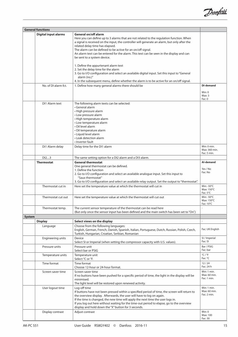
General functions
Digital input alarms General on/off alarmHere you can define up to 3 alarms that are not related to the regulation function. When a signal is received on the input, the controller will generate an alarm, but only after the related delay time has elapsed.The alarm can be defined to be active for an on/off signal.An alarm text can be entered for the alarm. This text can be seen in the display and can be sent to a system device.
1. Define the appurtenant alarm text2. Set the delay time for the alarm3. Go to I/O configuration and select an available digital input. Set this input to “General
alarm (no.)”4. In the subsequent menu, define whether the alarm is to be active for an on/off signal.
No. of DI alarm fct. 1. Define how many general alarms there should be DI-demand
Min: 0Max: 3Fac: 0
DI1 Alarm text The following alarm texts can be selected:• General alarm• High pressure alarm• Low pressure alarm• High temperature alarm• Low temperature alarm• Oil level alarm• Oil temperature alarm• Liquid level alarm• Leak detection alarm• Inverter fault
Di1 Alarm delay Delay time for the DI1 alarm Min: 0 min.Max: 360 min.Fac: 5 min.
DI2....3 The same setting option for a DI2 alarm and a DI3 alarm.
Thermostat General thermostatOne general thermostat can be defined.1. Define the function2. Go to I/O configuration and select an available analogue input. Set this input to
“Saux thermostat”3. Go to I/O configuration and select an available relay output. Set the output to “thermostat”.
AI-demand
Yes / NoFac: No
Thermostat cut in Here set the temperature value at which the thermostat will cut in Min: -50°CMax: 150°CFac: 5°C
Thermostat cut out Here set the temperature value at which the thermostat will cut out Min: -50°CMax: 150°CFac: 10°C
Thermostat temp. The current sensor temperature of the thermostat can be read here(But only once the sensor input has been defined and the main switch has been set to “On”.)
-
System
Display Select views on the display -
Language Choose from the following languages: English, German, French, Danish, Spanish, Italian, Portuguese, Dutch, Russian, Polish, Czech, Turkish, Hungarian, Croatian, Serbian, Romanian
Fac: UK English
Engineering units DeviceSelect SI or Imperial (when setting the compressor capacity with U.S. values).
SI / ImperialFac: SI
Pressure units Pressure unitSelect bar or PSIG
Bar / PSIGFac: bar
Temperature units Temperature unitSelect °C or °F.
°C / °FFac: °C
Time format Time formatChoose 12-hour or 24-hour format.
12 / 24Fac: 24 h
Screen saver time Screen saver timeIf no buttons have been pushed for a specific period of time, the light in the display will be minimised.The light level will be restored upon renewed activity.
Min: 1 min.Max: 60 min.Fac: 1 min.
User logout time Log-off timeIf buttons have not been pressed within a specified period of time, the screen will return to the overview display. Afterwards, the user will have to log on again.If the time is changed, the new time will apply the next time the user logs in.If you log out here without waiting for the time-out period to elapse, go to the overview display and hold down the “X” button for 3 seconds.
Min: 1 min.Max: 60 min.Fac: 2 min.
Display contrast Adjust contrast Min: 0Max: 100Fac: 30
16 User Guide RS8GY402 © Danfoss 2016-11 AK-PC 551
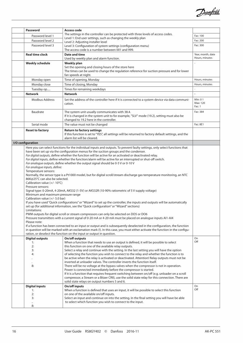
Password Access codeThe settings in the controller can be protected with three levels of access codes.Level 1: End user settings, such as changing the weekly plan Level 2: Adjusting installer levelLevel 3: Configuration of system settings (configuration menu)The access code is a number between 001 and 999.
Password level 1 Fac: 100
Password level 2 Fac: 200
Password level 3 Fac: 300
Real time clock Date and timeUsed by weekly plan and alarm function.
Year, month, dateHours, minutes
Weekly schedule Weekly planSet the opening and closing hours of the store hereThe times can be used to change the regulation reference for suction pressure and for lower fan speeds at night.
-
Monday open Time of opening, Monday Hours, minutes
Monday close Time of closing, Monday Hours, minutes
Tuesday op..... Times for remaining weekdays -
Network Network -
Modbus Address Set the address of the controller here if it is connected to a system device via data communi-cation.
Min: 0 1Max: 120Fac: 1
Baudrate The system unit usually communicates with 38.4.If it is changed in the system unit to for example, "SLV" mode (19.2), setting must also be changed to 19.2 here in the controller.
Fac: 384
Serial mode The value must not be changed Fac: 8E1
Reset to factory Return to factory settingsIf this function is set to “YES”, all settings will be returned to factory default settings, and the alarm list will be cleared.
I/O configuration
Here you can select functions for the individual inputs and outputs. To prevent faulty settings, only select functions that have been set up via the configuration menus for the suction groups and the condenser.For digital outputs, define whether the function will be active for an activated or deactivated relay.For digital inputs, define whether the function/alarm will be active for an interrupted or shut-off switch.For analogue outputs, define whether the output signal should be 0-5 V or 0-10 VFor analogue inputs, define:Temperature sensors:Normally, the sensor type is a Pt1000 model, but for digital scroll/stream discharge gas temperature monitoring, an NTC 86K@25°C can also be selected.Calibration value (+/- 10°C)Pressure sensors:Signal type: 0-20mA, 4-20mA, AKS32 (1-5V) or AKS32R (10-90% ratiometric of 5 V supply voltage)Minimum and maximum pressure rangeCalibration value (+/- 5.0 bar)If you have used “Quick configurations” or “Wizard” to set up the controller, the inputs and outputs will be automatically set up (for additional information, see the “Quick configuration” or “Wizard” sections)Limitations:PWM outputs for digital scroll or stream compressors can only be selected on DO5 or DO6Pressure transmitters with a current signal of 0-20 mA or 4-20 mA must be placed on analogue inputs AI1-AI4 Please note:If a function has been connected to an input or output and is subsequently deselected in the configuration, the function in question will be marked with an exclamation mark (!). In this case, you must either activate the function in the configu-ration, or deselect the function on the input or output in question.
Digital outputs1:2:3:4:..8:
On/off outputsWhen a function that needs to use an output is defined, it will be possible to select this function on one of the available relay outputs.Select a relay and continue with the setting. In the last setting you will have the option of selecting the function you wish to connect to the relay and whether the function is to be active when the relay is activated or deactivated. Attention! Relay outputs must not be inverted at unloader valves. The controller inverts the function itself.There will be no voltage at the bypass valves when the compressor is not in operation. Power is connected immediately before the compressor is started.If it is a function that requires frequent switching between on/off (e.g. unloader on a scroll compressor, a Stream or a Bitzer CRII), use the solid state relay for this connection. There are solid state relays on output numbers 5 and 6.
OnOff
Digital inputs1:2:3:..8:
On/off inputsWhen a function is defined that uses an input, it will be possible to select this function on one of the available on/off inputs.Select an input and continue on into the setting. In the final setting you will have be able to select which function you wish to connect to the input.
OnOff
AK-PC 551 User Guide RS8GY402 © Danfoss 2016-11 17
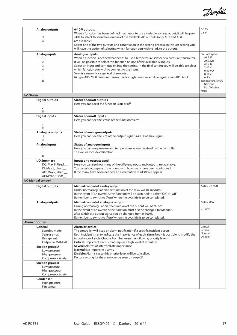
Analog outputs
3:4:
0-10 V outputs When a function has been defined that needs to use a variable voltage outlet, it will be pos-sible to select this function on one of the available AO outputs (only AO3 and AO4 are available).Select one of the two outputs and continue on in the setting process. In the last setting you will have the option of selecting which function you wish to link to the output.
0-10 V0-5 V
Analog inputs1:2:3:4:..8:
Analogue inputsWhen a function is defined that needs to use a temperature sensor or a pressure transmitter, it will be possible to select this function on one of the available AI inputs.Select an input and continue on into the setting. In the final setting you will be able to select which function you wish to connect to the input.Saux is a sensor for a general thermostat.(A type AKS 2050 pressure transmitter, for high pressure, emits a signal as an AKS 32R.)
Pressure signal:AKS 33AKS 32RAKS 322-10 V0-20 mA0-10 V0-5 V
Temperature signal:NTC-86K Pt 1000 ohm
None
I/O Status
Digital outputs1:.8:
Status of on/off outputsHere you can see if the function is on or off.
Digital inputs1:.8:
Status of on/off inputsHere you can see the status of the function/alarm.
Analogue outputs3:4:
Status of analogue outputsHere you can see the size of the output signals as a % of max. signal.
Analog inputs1:.8:
Status of analogue inputsHere you can see pressure and temperature values received by the controller. The values include calibration
I/O SummaryDO: Max 8, Used:__DI: Max 8, Used:__AO: Max 2, Used:__AI: Max 8, Used:__
Inputs and outputs usedHere you can see how many of the different inputs and outputs are available.You can also compare this amount with how many have been configured.If too many have been defined, an exclamation mark (!) will appear.
I/O Manual control
Digital outputs Manual control of a relay outputUnder normal regulation, the function of the relay will be in “Auto”.In the event of an override, the function will be switched to either “On” or “Off”.Remember to switch to “Auto” when the override is to be completed.
Auto / On / Off
Analog outputs Manual control of analogue outputDuring normal regulation, the function of the output will be “Auto”.In the event of an override, the function must first be changed to “Manual”, after which the output signal can be changed from 0-100%.Remember to switch to “Auto” when the override is to be completed.
Auto / Man
0-100%
Alarm priorities
GeneralStandby mode:Sensor error:Refrigerant:Output in MANUAL:
Alarm prioritiesThe controller will issue an alarm notification if a specific incident occurs. Each incident is set to indicate the importance of each alarm, but it is possible to modify the importance of each. Choose from between the following priority levels:Critical: Important alarms that require a high level of attention.Severe: Alarms of intermediate importanceNormal: No important alarmsDisable: Alarms set to this priority level will be cancelled.Factory setting for the alarm can be seen on page 21.
CriticalServereNormalDisable
Suction group ALow pressure:High pressure:Compressor safety:
Suction group BLow pressure:High pressure:Compressor safety:
CondenserHigh pressure:Fan safety:
18 User Guide RS8GY402 © Danfoss 2016-11 AK-PC 551
Quick setup
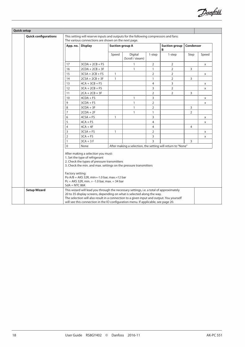
Quick configurations This setting will reserve inputs and outputs for the following compressors and fans:The various connections are shown on the next page.
App. no. Display Suction group A Suction group B
Condenser
Speed Digital(Scroll / steam)
1-step 1-step Step Speed
17 3CDA + 2CB + FS 1 2 2 x
16 2CDA + 2CB + 3F 1 1 2 3
15 3CSA + 2CB + FS 1 2 2 x
14 2CSA + 2CB + 3F 1 1 2 3
13 4CA + 3CB + FS 4 3 x
12 3CA + 2CB + FS 3 2 x
11 2CA + 2CB + 3F 2 2 3
10 4CDA + FS 1 3 x
9 3CDA + FS 1 2 x
8 3CDA + 3F 1 2 3
7 2CDA + 2F 1 1 2
6 4CSA + FS 1 3 x
5 4CA + FS 4 x
4 4CA + 4F 4 4
3 3CSA + FS 1 2 x
2 3CA + FS 3 x
1 3CA + 3 F 3 3
0 None After making a selection, the setting will return to “None”
After making a selection you must:1. Set the type of refrigerant2. Check the types of pressure transmitters 3. Check the min. and max. settings on the pressure transmitters
Factory setting:Po A/B = AKS 32R, min=-1.0 bar, max.=12 barPc = AKS 32R, min. = -1.0 bar, max. = 34 barSdA = NTC 86K
Setup Wizard This wizard will lead you through the necessary settings, i.e. a total of approximately 20 to 35 display screens, depending on what is selected along the way. The selection will also result in a connection to a given input and output. You yourself will see this connection in the IO configuration menu. If applicable, see page 20.
AK-PC 551 User Guide RS8GY402 © Danfoss 2016-11 19
Ap
p. n
o.D
isp
lay
Ou
tpu
tIn
pu
t
On/
Off
Ana
log
Ana
log
Dig
ital
DO
1D
O2
DO
3D
O4
DO
5D
O6
DO
7D
O8
AO
3A
O4
AI1
AI2
AI3
AI4
AI5
AI6
AI7
AI8
DI1
DI2
DI3
DI4
DI5
DI6
DI7
DI8
173C
DA
+ 2
CB
+ F
SC
1AC
2AC
3AC
1BC
1APW
MC
2BFa
nVS
DA
larm
Fan
Spee
dPo
APo
BPc
Sc3
SdA
D
igi
C1A
C2A
C3A
C1B
C2B
Mai
nSw
.Fa
nsa
fe.
162C
DA
+ 2
CB
+ 3
FC
1AC
2AC
1BC
2BC
1APW
MFa
n1Fa
n2Fa
n3Po
APo
BPc
Sc3
SdA
D
igi
C1A
C2A
C1B
C2B
Mai
nSw
.Fa
nsa
fe.
153C
SA +
2C
B +
FS
C1A
C2A
C3A
C1B
C2B
Fan
VSD
Ala
rmC
1A
Spee
dFa
n Sp
eed
PoA
PoB
PcSc
3C
1AC
2AC
3AC
1BC
2BM
ain
Sw.
Fan
safe
.
142C
SA +
2C
B +
3F
C1A
C2A
C1B
C2B
Fan1
Fan2
Fan3
Ala
rmC
1A
Spee
dPo
APo
BPc
Sc3
C1A
C2A
C1B
C2B
Mai
nSw
.Fa
nsa
fe.
134C
A +
3C
B +
FS
C1A
C2A
C3A
C4A
C1B
C2B
C3B
Ala
rmFa
n Sp
eed
PoA
PoB
PcSc
3C
1AC
2AC
3AC
4AC
1BC
2BC
3BFa
nsa
fe.
123C
A +
2C
B +
FS
C1A
C2A
C3A
C1B
C2B
Fan
VSD
Ala
rmFa
n Sp
eed
PoA
PoB
PcSc
3C
1AC
2AC
3AC
1BC
2BM
ain
Sw.
Fan
safe
.
112C
A +
2C
B +
3F
C1A
C2A
C1B
C2B
Fan1
Fan2
Fan3
Ala
rmPo
APo
BPc
Sc3
C1A
C2A
C1B
CB2
Mai
nSw
.Fa
nsa
fe.
104C
DA
+ F
SC
1C
2C
3C
4C
1PW
MFa
nVS
DA
larm
Fan
Spee
dPo
APc
Sc3
SdA
D
igi
C1
C2
C3
C4
Mai
nSw
.Fa
nsa
fe.
93C
DA
+ F
SC
1C
2C
3C
1PW
MFa
nVS
DA
larm
Fan
Spee
dPo
APc
Sc3
SdA
D
igi
C1
C2
C3
Mai
nSw
.Fa
nsa
fe.
83C
DA
+ 3
FC
1C
2C
3Fa
n1C
1PW
MFa
n2Fa
n3A
larm
PoA
PcSc
3Sd
A
Dig
iC
1C
2C
3M
ain
Sw.
Fan
safe
.
72C
DA
+ 2
FC
1C
2Fa
n1Fa
n2C
1PW
MA
larm
PoA
PcSc
3Sd
A
Dig
iC
1C
2M
ain
Sw.
Fan
safe
.
64C
SA +
FS
C1
C2
C3
C4
Fan
VSD
Ala
rmC
1 Sp
eed
Fan
Spee
dPo
APc
Sc3
C1
C2
C3
C4
Mai
nSw
.Fa
nsa
fe.
54C
A +
FS
C1
C2
C3
C4
Fan
VSD
Ala
rmFa
n Sp
eed
PoA
PcSc
3C
1C
2C
3C
4M
ain
Sw.
Fan
safe
.
44C
A +
4F
C1
C2
C3
C4
Fan1
Fan2
Fan3
Fan4
PoA
PcSc
3C
1C
2C
3C
4M
ain
Sw.
Fan
safe
.
33C
SA +
FS
C1
C2
C3
Fan
VSD
Ala
rmC
1 Sp
eed
Fan
Spee
dPo
APc
Sc3
C1
C2
C3
Mai
nSw
.Fa
nsa
fe.
23C
A +
FS
C1
C2
C3
Fan
VSD
Ala
rmFa
n Sp
eed
PoA
PcSc
3C
1C
2C
3M
ain
Sw.
Fan
safe
.
13C
A +
3 F
C1
C2
C3
Fan1
Fan2
Fan3
Ala
rmPo
APc
Sc3
C1
C2
C3
Mai
nSw
.Fa
nsa
fe.
0N
one
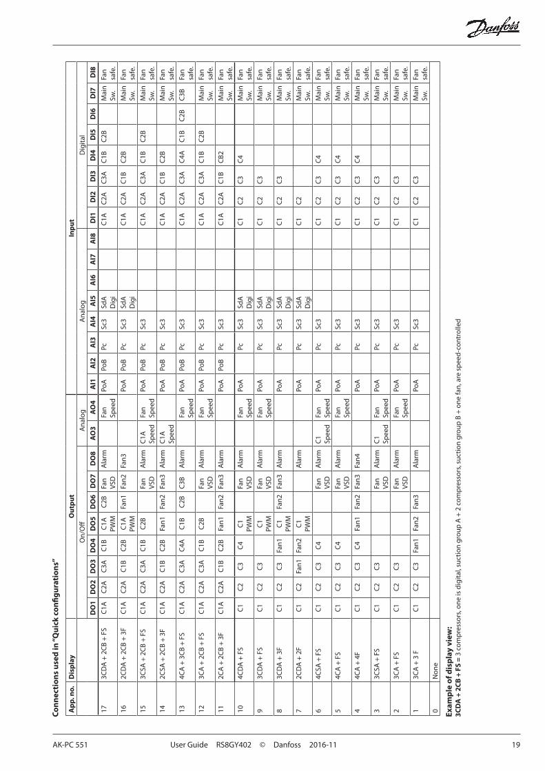
Exam
ple
of d
isp
lay
view
:3C
DA
+ 2
CB
+ F
S =
3 c
omp
ress
ors,
one
is d
igita
l, su
ctio
n gr
oup
A +
2 c
omp
ress
ors,
suc
tion
grou
p B
+ o
ne fa
n, a
re s
pee
d-co
ntro
lled
Co
nn
ecti
on
s u
sed
in “Q
uic
k co
nfi
gu
rati
on
s”
20 User Guide RS8GY402 © Danfoss 2016-11 AK-PC 551
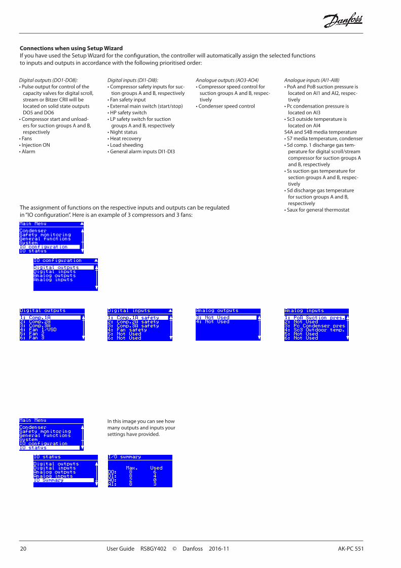
Connections when using Setup WizardIf you have used the Setup Wizard for the configuration, the controller will automatically assign the selected functions to inputs and outputs in accordance with the following prioritised order:
The assignment of functions on the respective inputs and outputs can be regulated in “IO configuration”. Here is an example of 3 compressors and 3 fans:
Digital outputs (DO1-DO8):• Pulse output for control of the
capacity valves for digital scroll, stream or Bitzer CRII will be located on solid state outputs DO5 and DO6
• Compressor start and unload-ers for suction groups A and B, respectively
• Fans• Injection ON• Alarm
Digital inputs (DI1-DI8):• Compressor safety inputs for suc-
tion groups A and B, respectively• Fan safety input• External main switch (start/stop)• HP safety switch• LP safety switch for suction
groups A and B, respectively• Night status• Heat recovery• Load sheeding• General alarm inputs DI1-DI3
Analogue outputs (AO3-AO4)• Compressor speed control for
suction groups A and B, respec-tively
• Condenser speed control
Analogue inputs (AI1-AI8)• PoA and PoB suction pressure is
located on AI1 and AI2, respec-tively
• Pc condensation pressure is located on AI3
• Sc3 outside temperature is located on AI4
S4A and S4B media temperature• S7 media temperature, condenser• Sd comp. 1 discharge gas tem-
perature for digital scroll/stream compressor for suction groups A and B, respectively
• Ss suction gas temperature for section groups A and B, respec-tively
• Sd discharge gas temperature for suction groups A and B, respectively
• Saux for general thermostat
In this image you can see how many outputs and inputs your settings have provided.
AK-PC 551 User Guide RS8GY402 © Danfoss 2016-11 21
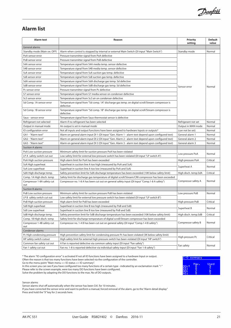
Alarm list
Alarm text Reason Priority setting
Default value
General alarms
Standby mode (Main sw. OFF) Alarm when control is stopped by internal or external Main Switch (DI input "Main Switch") Standby mode Normal
PoA sensor error Pressure transmitter signal from PoA defective
Sensor error Normal
PoB sensor error Pressure transmitter signal from PoB defective
S4A sensor error Temperature signal from S4A media temp. sensor defective
S4B sensor error Temperature signal from S4B media temp. sensor defective
SsA sensor error Temperature signal from SsA suction gas temp. defective
SsB sensor error Temperature signal from SsB suction gas temp. defective
SdA sensor error Temperature signal from SdA discharge gas temp. Sd defective
SdB sensor error Temperature signal from SdB discharge gas temp. Sd defective
Pc sensor error Pressure transmitter signal from Pc defective
S7 sensor error Temperature signal from S7 media sensor on condenser defective
Sc3 sensor error Temperature signal from Sc3 air on condenser defective
Sd Comp. 1A sensor error Temperature signal from "Sd comp. 1A" discharge gas temp. on digital scroll/Stream compressor is defective
Sd Comp. 1B sensor error Temperature signal from "Sd comp. 1B" discharge gas temp. on digital scroll/Stream compressor is defective
Saux - sensor error Temperature signal from Saux thermostat sensor is defective
Refrigerant not selected Alarm if no refrigerant has been selected Refrigerant not set Normal
Output in manual mode An output is set in manual mode Output in MAN mode Normal
IO configuration error Not all inputs and output functions have been assigned to hardware Inputs or outputs* (can not be set) Normal
GA1 - "Alarm text" Alarm on general alarm input DI 1 (DI input "Gen. Alarm 1 - alarm text depend upon configured text) General alarm 1 Normal
GA2 - "Alarm text" Alarm on general alarm input DI 2 (DI input "Gen. Alarm 2 - alarm text depend upon configured text) General alarm 2 Normal
GA3 - "Alarm text" Alarm on general alarm input DI 3 (DI input "Gen. Alarm 3 - alarm text depend upon configured text) General alarm 3 Normal
Suction A alarms
PoA Low suction pressure Minimum safety limit for suction pressure PoA has been violatedLow pressure PoA Normal
LP A safety switch cut out Low safety limit for external low pressure switch has been violated (DI input "LP switch A")
PoA High suction pressure High alarm limit for PoA has been exceeded High pressure PoA Critical
SsA High superheat Superheat in suction line A too high (measured by PoA and SsA)Superheat A Normal
SsA Low superheat Superheat in suction line A too low (measured by PoA and SsA)
SdA High discharge temp. Safety prevention limit for SdA discharge temperature has been exceeded (10K below safety limit) High disch. temp.SdA Critical
Comp. 1A High disch. temp Safety limit for discharge gas temperature of digital scroll/Stream/CRII compressor has been exceededCompressor safety A NormalCompressor 1-8A safety cut
outCompressor no. 1-8 A has been cut out on general safety input (DI input "Comp.1-8 A safety")
Suction B alarms
PoB Low suction pressure Minimum safety limit for suction pressure PoB has been violated Low pressure PoB
Normal
LP B safety switch cut out Low safety limit for external low pressure switch has been violated (DI input "LP switch B")
PoB High suction pressure High alarm limit for PoB has been exceeded High pressure PoB Critical
SsB High superheat Superheat in suction line B too high (measured by PoB and SsB)Superheat B Normal
SsB Low superheat Superheat in suction line B too low (measured by PoB and SsB)
SdB High discharge temp. Safety prevention limit for SdB discharge temperature has been exceeded (10K below safety limit) High disch. temp.SdB Critical
Comp. 1B High disch. temp Safety limit for discharge temperature of digital scroll/Stream compressor has been exceededCompressor safety B NormalCompressor 1-4B safety cut
outCompressor no. 1-4 B has been cut out on general safety (DI input "Comp.1-4 B safety")
Condenser alarms
Pc High condensing pressure High prevention safety limit for condensing pressure Pc has been violated (3K below safety limit)High pressure Pc Critical
HP safety switch cutout High safety limit for external high pressure switch has been violated (DI input "HP switch")
Common fan safety cut out A Fan is reported defective via common safety input (DI input "Fan safety")Fan safety Normal
Fan 1 safety cut out Fan no. 1-8 is reported defective via individual safety input (DI input "Fan 1-8 safety")
* The alarm "IO configuration error" is activated if not all IO functions have been assigned to a hardware Input or output.Often the reason is that too many functions have been selected via the configuration of the controller. Go to the menu point "Main menu => IO status => IO summary".In this screen you can see if you have configured too many functions of a certain type - indicated by an exclamation mark " ! "Please refer to the screen example, were too many DO functions have been configured.Solve the problem by adapting the DO functions to the max. No of DO outputs.
Sensor alarmsSensor alarms shut off automatically when the sensor has been O.K. for 10 minutes. If you have corrected the sensor error and want to perform a manual, forced removal of the alarm, go to the “Alarm detail display”Press and hold the “X” key for 2 seconds here.
22 User Guide RS8GY402 © Danfoss 2016-11 AK-PC 551
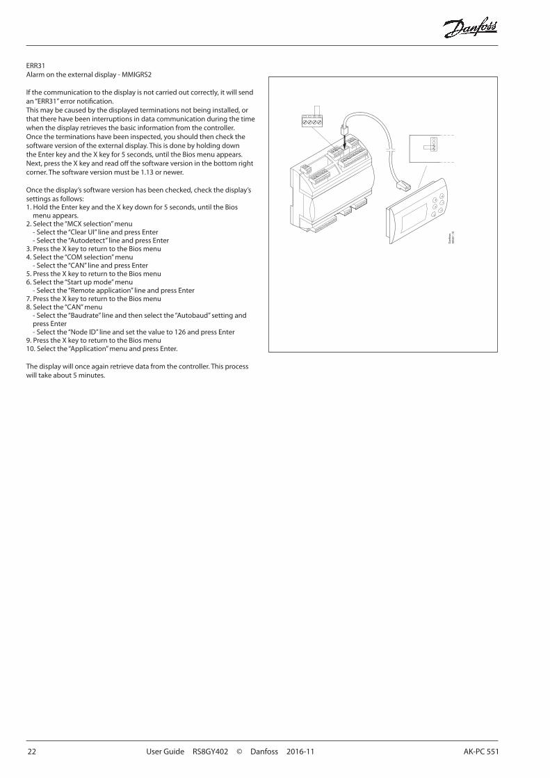
ERR31 Alarm on the external display - MMIGRS2
If the communication to the display is not carried out correctly, it will send an “ERR31” error notification. This may be caused by the displayed terminations not being installed, or that there have been interruptions in data communication during the time when the display retrieves the basic information from the controller. Once the terminations have been inspected, you should then check the software version of the external display. This is done by holding down the Enter key and the X key for 5 seconds, until the Bios menu appears. Next, press the X key and read off the software version in the bottom right corner. The software version must be 1.13 or newer.
Once the display’s software version has been checked, check the display’s settings as follows:1. Hold the Enter key and the X key down for 5 seconds, until the Bios
menu appears. 2. Select the “MCX selection” menu - Select the “Clear UI” line and press Enter - Select the “Autodetect” line and press Enter3. Press the X key to return to the Bios menu4. Select the “COM selection” menu - Select the “CAN” line and press Enter 5. Press the X key to return to the Bios menu 6. Select the “Start up mode” menu - Select the “Remote application” line and press Enter 7. Press the X key to return to the Bios menu 8. Select the “CAN” menu - Select the “Baudrate” line and then select the “Autobaud” setting and
press Enter - Select the “Node ID” line and set the value to 126 and press Enter9. Press the X key to return to the Bios menu 10. Select the “Application” menu and press Enter.
The display will once again retrieve data from the controller. This process will take about 5 minutes.
AK-PC 551 User Guide RS8GY402 © Danfoss 2016-11 23
Connections
DO DO1 DO2 DO3 DO4 DO5 DO6 DO7 DO8 Σ 1-8
I Max. 10 A(3.5)
10 A(3.5)
6 A(4)
6 A(4)
0.5 Amin. 50 mAIoff < 1,5 mA
0.5 Amin. 50 mAIoff < 1,5 mA
6 A(4)
6 A(4)
32 A
U All 24 V or all 230 V a.c.
AKS 32
AKS 33
AKS 32R
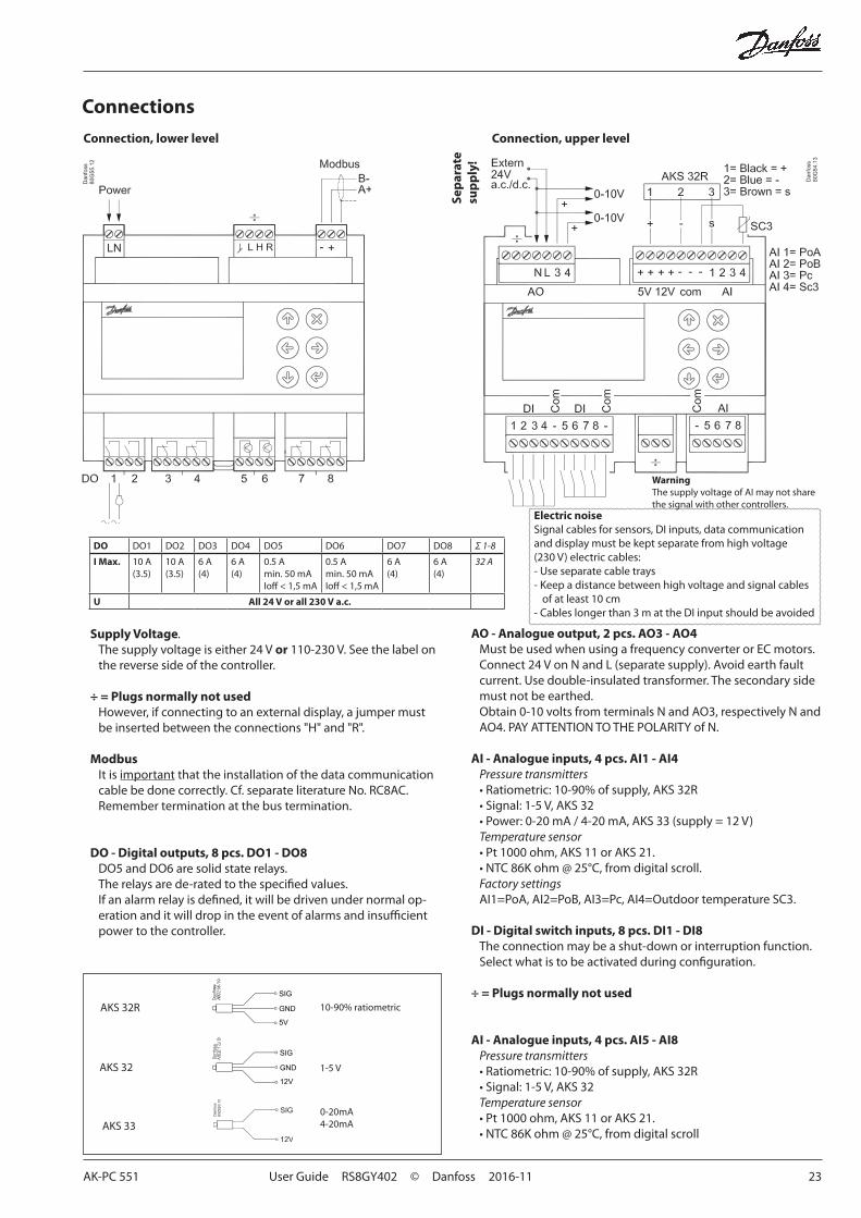
Connection, lower level Connection, upper level
Supply Voltage. The supply voltage is either 24 V or 110-230 V. See the label on the reverse side of the controller.
÷ = Plugs normally not usedHowever, if connecting to an external display, a jumper must be inserted between the connections "H" and "R".
ModbusIt is important that the installation of the data communication cable be done correctly. Cf. separate literature No. RC8AC.Remember termination at the bus termination.
DO - Digital outputs, 8 pcs. DO1 - DO8DO5 and DO6 are solid state relays. The relays are de-rated to the specified values.If an alarm relay is defined, it will be driven under normal op-eration and it will drop in the event of alarms and insufficient power to the controller.
AO - Analogue output, 2 pcs. AO3 - AO4Must be used when using a frequency converter or EC motors.Connect 24 V on N and L (separate supply). Avoid earth fault current. Use double-insulated transformer. The secondary side must not be earthed. Obtain 0-10 volts from terminals N and AO3, respectively N and AO4. PAY ATTENTION TO THE POLARITY of N.
AI - Analogue inputs, 4 pcs. AI1 - AI4Pressure transmitters • Ratiometric: 10-90% of supply, AKS 32R• Signal: 1-5 V, AKS 32• Power: 0-20 mA / 4-20 mA, AKS 33 (supply = 12 V)Temperature sensor• Pt 1000 ohm, AKS 11 or AKS 21.• NTC 86K ohm @ 25°C, from digital scroll.Factory settingsAI1=PoA, AI2=PoB, AI3=Pc, AI4=Outdoor temperature SC3.
DI - Digital switch inputs, 8 pcs. DI1 - DI8The connection may be a shut-down or interruption function. Select what is to be activated during configuration.
÷ = Plugs normally not used
AI - Analogue inputs, 4 pcs. AI5 - AI8Pressure transmitters • Ratiometric: 10-90% of supply, AKS 32R• Signal: 1-5 V, AKS 32Temperature sensor• Pt 1000 ohm, AKS 11 or AKS 21.• NTC 86K ohm @ 25°C, from digital scroll
10-90% ratiometric
1-5 V
0-20mA4-20mA
WarningThe supply voltage of AI may not share the signal with other controllers.
Sep
arat
e su
pp
ly!
Electric noiseSignal cables for sensors, DI inputs, data communication and display must be kept separate from high voltage (230 V) electric cables:- Use separate cable trays- Keep a distance between high voltage and signal cables
of at least 10 cm- Cables longer than 3 m at the DI input should be avoided
24 User Guide RS8GY402 © Danfoss 2016-11 AK-PC 551
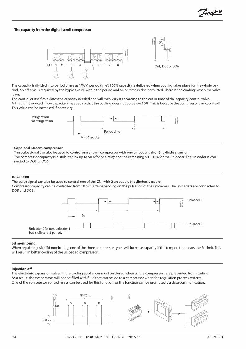
The capacity is divided into period times as "PWM period time". 100% capacity is delivered when cooling takes place for the whole pe-riod. An off time is required by the bypass valve within the period and an on time is also permitted. There is "no cooling" when the valve is on.The controller itself calculates the capacity needed and will then vary it according to the cut-in time of the capacity control valve.A limit is introduced if low capacity is needed so that the cooling does not go below 10%. This is because the compressor can cool itself. This value can be increased if necessary.
The capacity from the digital scroll compressor
Only DO5 or DO6
RefrigerationNo refrigeration
Copeland Stream compressorThe pulse signal can also be used to control one stream compressor with one unloader valve *(4 cylinders version).The compressor capacity is distributed by up to 50% for one relay and the remaining 50-100% for the unloader. The unloader is con-nected to DO5 or DO6.
Injection offThe electronic expansion valves in the cooling appliances must be closed when all the compressors are prevented from starting. As a result, the evaporators will not be filled with fluid that can be led to a compressor when the regulation process restarts.One of the compressor control relays can be used for this function, or the function can be prompted via data communication.
Period time
Min. Capacity
Sd monitoringWhen regulating with Sd monitoring, one of the three compressor types will increase capacity if the temperature nears the Sd limit. This will result in better cooling of the unloaded compressor.
Bitzer CRIIThe pulse signal can also be used to control one of the CRII with 2 unloaders (4 cylinders version).Compressor capacity can be controlled from 10 to 100% depending on the pulsation of the unloaders. The unloaders are connected to DO5 and DO6..
Unloader 2 follows unloader 1 but is offset a ½ period.
Unloader 1
Unloader 2
AK-PC 551 User Guide RS8GY402 © Danfoss 2016-11 25
OrderingType Function Operation Supply voltage Code no.
AK-PC 551 Capacity controller
With buttons and display
230 V 080G0281
24 V 080G0283
With external display and 1.5 m wire for display unit
230 V 080G0282
24 V 080G0288
MMIGRS2 Display unit With buttons and display - 080G0294
Wire for display unit, L = 1.5 m, 1 pcs. 080G0075
Wire for display unit, L = 3 m, 1 pcs. 080G0076
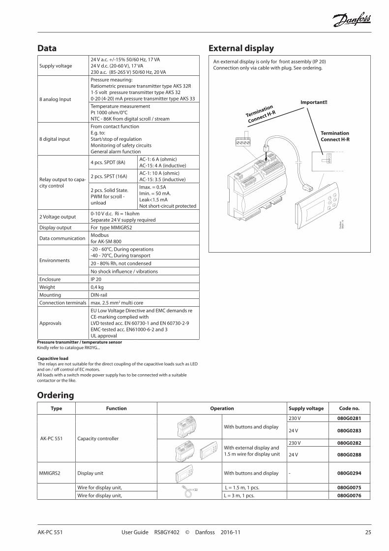
Supply voltage24 V a.c. +/-15% 50/60 Hz, 17 VA24 V d.c. (20-60 V), 17 VA230 a.c. (85-265 V) 50/60 Hz, 20 VA
8 analog Input
Pressure meauring:Ratiometric pressure transmitter type AKS 32R1-5 volt pressure transmitter type AKS 320-20 (4-20) mA pressure transmitter type AKS 33
Temperature measurementPt 1000 ohm/0°CNTC - 86K from digital scroll / stream
8 digital input
From contact functionE.g. to:Start/stop of regulationMonitoring of safety circuitsGeneral alarm function
Relay output to capa-city control
4 pcs. SPDT (8A)AC-1: 6 A (ohmic)AC-15: 4 A (inductive)
2 pcs. SPST (16A)AC-1: 10 A (ohmic)AC-15: 3.5 (inductive)
2 pcs. Solid State.PWM for scroll - unload
Imax. = 0.5AImin. = 50 mA. Leak<1.5 mANot short-circuit protected
2 Voltage output0-10 V d.c. Ri = 1kohmSeparate 24 V supply required
Display output For type MMIGRS2
Data communicationModbusfor AK-SM 800
Environments
-20 - 60°C, During operations-40 - 70°C, During transport
20 - 80% Rh, not condensed
No shock influence / vibrations
Enclosure IP 20
Weight 0,4 kg
Mounting DIN-rail
Connection terminals max. 2.5 mm2 multi core
Approvals
EU Low Voltage Directive and EMC demands re CE-marking complied withLVD tested acc. EN 60730-1 and EN 60730-2-9EMC-tested acc. EN61000-6-2 and 3UL approval
Data External display
Pressure transmitter / temperature sensorKindly refer to catalogue RK0YG...
An external display is only for front assembly (IP 20)Connection only via cable with plug. See ordering.
Important!!
TerminationConnect H-R
Termination
Connect H-R
Capacitive load The relays are not suitable for the direct coupling of the capacitive loads such as LED and on / off control of EC motors.All loads with a switch mode power supply has to be connected with a suitable contactor or the like.
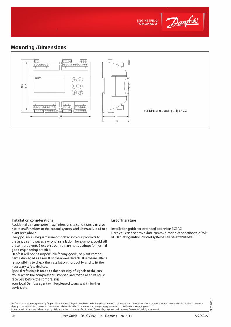
26 User Guide RS8GY402 © Danfoss 2016-11 AK-PC 551
List of literature
Installation guide for extended operation RC8ACHere you can see how a data communication connection to ADAP-KOOL® Refrigeration control systems can be established.
AD
AP-
KOO
L®
Danfoss can accept no responsibility for possible errors in catalogues, brochures and other printed material. Danfoss reserves the right to alter its products without notice. This also applies to productsalready on order provided that such alternations can be made without subsequential changes being necessary in specifications already agreed.All trademarks in this material are property of the respecitve companies. Danfoss and Danfoss logotype are trademarks of Danfoss A/S. All rights reserved.
Installation considerationsAccidental damage, poor installation, or site conditions, can give rise to malfunctions of the control system, and ultimately lead to a plant breakdown.Every possible safeguard is incorporated into our products to prevent this. However, a wrong installation, for example, could still present problems. Electronic controls are no substitute for normal, good engineering practice.Danfoss will not be responsible for any goods, or plant compo-nents, damaged as a result of the above defects. It is the installer's responsibility to check the installation thoroughly, and to fit the necessary safety devices.Special reference is made to the necessity of signals to the con-troller when the compressor is stopped and to the need of liquid receivers before the compressors.Your local Danfoss agent will be pleased to assist with further advice, etc.
Mounting /Dimensions
For DIN rail mounting only (IP 20)