Capacity 2.000 kg SD26L - Weber UK Ltd · 27 62 202 00 62 202 00 1 Saksehalvp. m. tank Scissor half...
13
0825006-010110 User’s guide Hand-hydraulic Jacking Beam SD20L Capacity 2.000 kg SD26L Capacity 2.600 kg GB WEBER UK LTD Unit 10, First Avenue, Bluebridge Ind. Est. Halstead, Essex. CO9 2EX Tel.: 01787 476319 Fax: 01787 274926 E-mail: [email protected] www.weberuk.com
Transcript of Capacity 2.000 kg SD26L - Weber UK Ltd · 27 62 202 00 62 202 00 1 Saksehalvp. m. tank Scissor half...

0825006-0
1011
0
User’s guide Hand-hydraulic Jacking Beam
SD20L Capacity 2.000 kg
SD26L Capacity 2.600 kg
GB
WEBER UK LTDUnit 10, First Avenue, Bluebridge Ind. Est. Halstead, Essex. CO9 2EXTel.: 01787 476319Fax: 01787 274926E-mail: [email protected]

Fig. 1
Assembly Instructions for Support Arms 1. Lift the jacking beam out of the box (you may cut open
the box), and place the jacking beam be-tween the ramps in the desired height above the floor, e.g. on a wooden board. Warning: Only lift with top beam and main frame tied together! If not tied together cylinder will not support the top beam when being lifted, and the top beam will crash when releasing the safety stop.
2. Cut the strips. Take the separate box with the support arms and mount flanges and axles with rolls in holes depending on the desired top beam minimum height compared to the ramps and floor. Be aware that you may have multiple choices for both flanges and axles (please refer to fig. 1). You may also alter the height 12,5 mm by turning the black support arms in the main frame. Warning: Remember to assembly the screws 0263000 again to secure the support arms against crashing.
3. Having placed the jacking beam in the right position grease the axles. Tighten screws and nuts thoroughly.
GB

GB
WARNING: To ensure against collapsing (flat support arms, rolls without steering etc.) the support arms must be secured by locking them, once the supports are resting safely in both sides. The relevant supports include 2 square joints with screw and nut to be mounted one in each support arm (please refer to fig. 2). In case of danger of derailing or any other form of cras-hing it is important to take the relevant precautions, especially for lift types as fig.3. There may be difficulties in having this lift type keep the ramps parallel. It is up to the assessment of the serviceman how to carry out the securing of the support arms in each case.
Fig. 2
Fig. 3
(det viste ophæng er kun et eksempel)
(the supports shown are only an example)
(die Aufhängungen sind nur Beispiele)

Fig. 2
Fig. 3
GB WARNING: To ensure against collapsing (flat support arms, rolls without steering etc.) the support arms must be secured by locking them, once the supports are resting safely in both sides. The relevant supports include 2 square joints with screw and nut to be mounted one in each support arm (please refer to fig. 2). In case of danger of derailing or any other form of cras-hing it is important to take the relevant precautions, especially for lift types as fig.3. There may be difficulties in having this lift type keep the ramps parallel. It is up to the assessment of the serviceman how to carry out the securing of the support arms in each case.

SD20L / SD26L WARNING - safe usage instructions
1. The jacking beam is only to be mounted on lifts approved by the lift manufacturer for mounting of jacking beams - be aware that not all lifts are approved. Rated beam capacity must be max. 2/3 of vehicle lift capacity.
2. Mount the jacking beam with adequate support arms on horizontal, parallel and solid rails and secure it against crashing before use. See para-graph “Assembly Instructions for Support Arms”.
3. The jacking beam has been constructed for operation only by trained personnel, having read and understood this manual.
4. Check before each lift, that the support arms are correctly placed on rail of lift or pit edge.
5. This is a lifting device only. Do not move or trans-port vehicle with jacking beam.
6. Always lower the jacking beam to the nearest safety stop immediately - or use axle stands for support - before working on vehicle.
7. Do not overload, for instance due to sudden exter-nal load. Overload can cause damage or failure of jack.
8. Lift only on points as specified by automaker. During lifting be attentive that the saddles cannot slide.
9. When lifting the complete vehicle by means of 2 jacking beams they shall be placed minimum 0,85 m from each other.
10. Gravity of load must always be placed centrally. When lifting by means of only one saddle always place it in the centre of the jacking beam. Also, the 2 extension arms must only be used simulta-neously.
11. The wheels of the vehicle is to point forward and be chocked.
12. No person must remain in, on or under a vehicle when lifted or supported only by the jacking beam.
13. The operator must observe, that the jacking beam can be operated without any danger to himself and others.
14. The jacking beam as well as the safety valve is not to be altered.
15. Failure to follow these warnings may result in loss of load, damage to jack, and/or failure resulting in personal injury or property damage.
GB AssemblySee paragraph “Assembly Instructions for Support Arms” on previous pages.
UseLifting: Pump the handle. Lower to the nearest safety stop by turning opposite.
Lowering: Lift a little to allow release of safety stop. Turn both handles counter clockwise (release valve to the left, release for safety stop to the right). Both handles automatically return to neutral.
MaintenanceMaintenance and repairs must always be carried out by qualified personnel. Daily: Check jacking beam and supports for damage - and the correct placement of supports. Monthly: Lubricate all moving parts with oil. Oil refill and check: Lift to maximum height without load and remove filler plug (11). Correct oil-level is up to the lowest hole. Oil quantity: 0,6 l. - Any good hydraulic oil with viscosity ISO VG 15 can be used. Never use brake fluid.
Safety inspectionIn accordance with national regulations - yet, at least once a year - the following parts must be checked by an expert: Supports and support arms (security against crashing), abnormal wear and damages, weldings and the hydraulic system for leaks.
Possible faults and how to overcome them1. T he jacking beam cannot lift to maximum height:
Refill the oil tank. (See “Maintenance”).2. T he jacking beam cannot lift enough: Check that
release handle is on “neutral” and can move freely. Both release 6222600 (adjusted with nut 0262700) and release arm 6222702 (adjusted with counternuts 2 x 0201600 on the pump’s release spindle) must be loose to allow the release valve to close tightly.
3. T he jacking beam cannot lower to minimum position: Check for damages; lubricate mechanical parts.
4. T he jacking beam continues to lower after letting go of the release handle: Ventilate the hydraulic cylinder by screw (10). Warning: The jacking beam is not to be loaded.
DestructionThe oil must be drained off and legally disposed of.

SD20LSD26L

DK GB DSD20L SD26L
Pos. Art. no. Art. no. Pcs. Benævnelse Description Bezeichnung62 250 00 62 365 00 Håndhydraulisk Hand-hydraulic Handhydraulischer
saksedonkraft jacking beam Scherenheber1 02 003 00 02 003 00 1 Møtrik Nut Mutter2 02 099 00 02 099 00 2 Skrue Screw Schraube 3 02 204 00 02 204 00 2 Seegerring Circlip Seegerring4 02 205 00 02 205 00 2 Seegerring Circlip Seegerring5 02 206 00 02 206 00 6 Seegerring Circlip Seegerring6 02 222 00 02 222 00 2 Seegerring Circlip Seegerring7 02 318 00 02 318 00 1 Skrue Screw Schraube 8 02 350 00 02 350 00 3 Skrue Screw Schraube 9 02 418 00 02 418 00 1 Slangestuds Hose union Schlauchstuz
10 02 421 00 02 421 00 2 Slangeklemme Hose clamp Schlauchklemme 11 02 470 00 02 470 00 2 Prop Plug Füllpfropfen 12 02 543 00 02 543 00 1 Kædesamleled Chain Link Kettenglied 13 02 547 00 02 547 00 1 Plastgreb PVC handle Plasthandgriff14 02 556 00 02 556 00 4 Leje Bearing Lager 15 02 558 00 02 558 00 1 Hyraulikslange Hydraulic hose Hydraulikschlauch16 02 627 00 02 627 00 1 Møtrik Nut Mutter17 02 630 00 02 630 00 7 Skrue Screw Schraube18 02 646 00 02 646 00 4 Skrue Screw Schraube19 02 649 00 02 649 00 3 Afdækningsknap Cover button Abdeckknopf 20 02 651 00 02 651 00 1 Afdækningsknap Cover button Abdeckknopf 21 02 705 00 02 705 00 2 Leje Bearing Lager 22 02 754 00 02 754 00 1 Fjeder Spring Feder23 62 022 00 62 022 00 2 Forlænger, 45 mm Extension, 45 mm Verlängerung, 45 mm 24 62 023 00 62 023 00 2 Forlænger, 90 mm Extension, 90 mm Verlängerung, 90mm 25 62 024 00 62 024 00 2 Sadel Saddle Sattel 26 62 201 00 62 201 00 1 Bundramme Bottom frame Bodenrahmen27 62 202 00 62 202 00 1 Saksehalvp. m. tank Scissor half with tank Scherenhälfte m. Behälter28 62 203 00 62 203 00 2 Saksearm udv. Outer scissor arm Scherenarm, ausw.29 62 207 00 62 207 00 1 Sikkerhedsstop Safety stop Sicherheitsstopp30 62 207 04 62 207 04 1 Afstandsbøsning Distance bushing Abstandsbuchse31 62 210 00 62 210 00 2 Kurve Curve Krümmung 32 62 211 00 62 211 00 2 Aksel Axle Achse33 62 212 00 62 212 00 1 Aksel Axle Achse34 62 213 00 62 213 00 1 Aksel Axle Achse35 62 215 00 62 215 00 1 Aksel Axle Achse36 62 216 00 62 216 00 4 Rulle Roller Rollen37 62 217 00 62 217 00 2 Rulle Roller Rollen38 62 218 00 62 218 00 2 Rulleaksel Roller axle Rollenachse 39 62 219 00 62 219 00 2 Lejetap Axle journal Lagerzapfen 40 62 225 00 62 225 00 1 Styreklods f. udløser Guide block f. release Steuerklotz f. Auslöser41 62 226 00 62 226 00 1 Udløser Release Auslöser 42 62 227 02 62 227 02 1 Udløserarm Release lever Auslöserarm 43 62 230 00 62 230 00 1 Topbjælke Top beam Traverse44 62 255 00 62 255 00 1 Betjeningspanel Control panel Bedienfeld45 62 260 00 62 260 00 2 Udtræk Base support arm Grundaufhängung 46 91 204 00 91 204 00 1 Olierør Oil tube Ölrohr47 91 205 00 91 205 00 1 Forskruning Gland Verschraubung 48 91 225 00 91 225 00 1 Nikketøjskonsol Tipping Gear Bracket Konsole für Kippvorrichtung 49 91 230 00 91 230 00 1 Cylinder, komplet Cylinder complete Zylinder, komplett50 91 238 00 91 238 00 1 Pumpehåndtag Pump lever Pumphebel51 91 238 04 91 238 04 1 Lejebøsning Bearing bush Lagerbuchse52 91 244 00 91 244 00 1 Sugeslange Suction hose Saugschlauch 53 91 250 20 91 250 26 1 Pumpe, komplet Pump, complete Pump, komplett
62 255 00
DK GB D
DK GB D
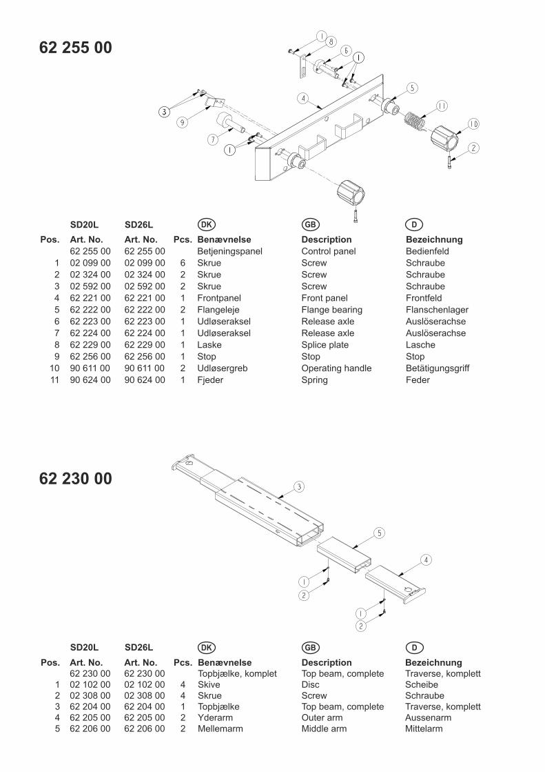
62 230 00
Pos. Art. No. Art. No. Pcs. Benævnelse Description Bezeichnung
62 255 00 62 255 00 Betjeningspanel Control panel Bedienfeld
1 02 099 00 02 099 00 6 Skrue Screw Schraube
2 02 324 00 02 324 00 2 Skrue Screw Schraube
3 02 592 00 02 592 00 2 Skrue Screw Schraube
4 62 221 00 62 221 00 1 Frontpanel Front panel Frontfeld
5 62 222 00 62 222 00 2 Flangeleje Flange bearing Flanschenlager
6 62 223 00 62 223 00 1 Udløseraksel Release axle Auslöserachse
7 62 224 00 62 224 00 1 Udløseraksel Release axle Auslöserachse
8 62 229 00 62 229 00 1 Laske Splice plate Lasche
9 62 256 00 62 256 00 1 Stop Stop Stop
10 90 611 00 90 611 00 2 Udløsergreb Operating handle Betätigungsgriff
11 90 624 00 90 624 00 1 Fjeder Spring Feder
SD20L SD26L
SD20L SD26L
Pos. Art. No. Art. No. Pcs. Benævnelse Description Bezeichnung62 230 00 62 230 00 Topbjælke, komplet Top beam, complete Traverse, komplett
1 02 102 00 02 102 00 4 Skive Disc Scheibe2 02 308 00 02 308 00 4 Skrue Screw Schraube3 62 204 00 62 204 00 1 Topbjælke Top beam, complete Traverse, komplett4 62 205 00 62 205 00 2 Yderarm Outer arm Aussenarm5 62 206 00 62 206 00 2 Mellemarm Middle arm Mittelarm

91 250 20 91 250 26
DK GB DSD20L SD26L
DK: De med * mærkede dele leveres i komplet pakningssæt. Anvend altid originale reservedele. Angiv venligst altid model og reservedels- nummer. Alle hoveddele kan ikke forventes leveret efter produktionsophør af model.
GB: * in dicate parts included in repair set. Please always state model and part number. Do always apply original spare parts. All major parts may not be provided as spare parts after discontinuation of production of a model.
D: Di e mit * markierten Teile sind im Dichtungssatz enthalten. Bitte immer Modell und Ersatzteilnummer auf Ihren Bestellungen angeben. Immer nur Originalteile verwenden. Lieferung von allen Hauptteilen als Ersatzteile kann nach Produktions-Einstellung eines Modelles nicht erwartet werden.
Pos. Art. No. Art. No. Pcs.Benævnelse Description Bezeichnung91 250 20 91 250 26 Pumpe, komplet Pump, complete Pumpe, komplett
*1 01 000 00 01 000 00 1 O-ring O-ring O-ring*2 01 039 00 01 039 00 1 O-ring O-ring O-ring*3 01 057 00 01 057 00 1 O-ring O-ring O-ring*4 01 096 00 01 096 00 2 O-ring O-ring O-ring5 02 000 13 02 000 13 2 Fjeder Spring Feder6 02 000 22 02 000 22 1 Skrue Screw Schraube7 02 016 00 02 016 00 2 Møtrik Nut Mutter8 02 054 00 02 054 00 1 Fjeder Spring Feder9 02 078 00 02 078 00 1 Fjeder Spring Feder
10 02 108 00 02 108 00 1 Skive Disc Scheibe*11 02 127 01 02 127 01 1 Al skive Al Disc Al Scheibe*12 02 132 01 02 132 01 1 Al skive Al Disc Al Scheibe*13 02 164 00 02 164 00 2 Kugle, Ø5 Ball, Ø5 Kugel, Ø5*14 02 183 00 02 183 00 2 Kugle, Ø2,5 Ball, Ø2,5 Kugel, Ø2,515 02 510 00 02 510 00 1 Fitting Fitting Fitting
*16 02 511 00 02 511 00 1 Filter Filter Filter17 02 584 00 02 584 00 2 Prop Plug Pfropfen18 02 820 00 02 820 00 1 Fitting Fitting Fitting
*19 02 831 00 02 831 00 4 Al skive Al Disc Al Scheibe*20 90 667 00 90 667 00 1 Ventilindsats 1/8”, Ø3,5/2 Valve cartridge 1/8”, Ø3,5/2 Ventileinsatz 1/8” Ø3,5/221 90 674 00 90 674 00 1 Justerskrue Adjusting screw Justierschraube
*22 90 695 00 90 695 00 2 Ventilindsats 1/8”, Ø3,5 Valve cartridge 1/8”, Ø3,5 Ventileinsatz 1/8” Ø3,5*23 90 744 00 90 744 00 1 Ventilindsats 1/8”, Ø2 Valve cartridge 1/8”, Ø2 Ventileinsatz 1/8” Ø224 91 056 00 91 056 00 1 Udløserspindel Release spindle Auslöserspindel25 91 057 10 91 057 10 1 Udløserstyr Release guide Auslösersteuer26 91 226 03 91 226 03 1 Pumpeblok Pump block Pumpblock27 91 227 00 91 227 00 1 Pakbox Packing box Packbox
*28 91 228 00 91 228 00 1 Pumpestempel Pump piston, cpl Pumpkolben, kpl* 09 068 00 09 068 00 Pakningssæt Repair kit Dichtungssatz

91 230 00
DK GB DSD20L SD26L
DK: De med * mærkede dele leveres i komplet pakningssæt. Anvend altid originale reservedele. Angiv venligst altid model og reservedels- nummer. Alle hoveddele kan ikke forventes leveret efter produktionsophør af model.
GB: * in dicate parts included in repair set. Please always state model and part number. Do always apply original spare parts. All major parts may not be provided as spare parts after discontinuation of production of a model.
D: Di e mit * markierten Teile sind im Dichtungssatz enthalten. Bitte immer Modell und Ersatzteilnummer auf Ihren Bestellungen angeben. Immer nur Originalteile verwenden. Lieferung von allen Hauptteilen als Ersatzteile kann nach Produktions-Einstellung eines Modelles nicht erwartet werden.
Pos. Art. No. Art. No. Pcs. Benævnelse Description Beschreibung91 230 00 91 230 00 Cylinder, komplet Cylinder complete Zylinder, komplett
*1 01 020 00 01 020 00 1 O-ring O-ring O-ring*2 01 029 00 01 029 00 1 O-ring O-ring O-ring*3 01 155 00 01 155 00 1 Back-up ring Back-up ring Stützscheibe*4 01 255 00 01 255 00 1 Afstryger Scraper Abstreifer*5 01 438 00 01 438 00 1 Pakning Seal Dichtung6 02 071 00 02 071 00 1 Trykfjeder Compression spring Druckfeder
*7 02 291 00 02 291 00 1 Kugle, Ø3,5 Ball, Ø3,5 Kugel, Ø3,5*8 02 292 00 02 292 00 1 Kugle, Ø6,5 Ball, Ø6,5 Kugel, Ø6,5*9 02 542 00 02 542 00 1 Seegerring Circlip Seegerring
*10 02 629 00 02 629 00 1 Pinolskrue Pinol screw Pinolschraube11 02 633 00 02 633 00 1 Nippelmuffe Bushing Muffe12 02 820 00 02 820 00 1 Forskruning Fitting Verschraubung13 90 817 00 90 817 00 1 Ventilskive Valve disc Ventilscheibe14 91 231 00 91 231 00 1 Cylinder Cylinder Zylinder15 91 232 00 91 232 00 1 Stempelstok Piston rod Kolbenstange
* 09 044 00 09 044 00 Pakningssæt Repair kit Dichtungssatz

HYDRAULIK DIAGRAMHYDRAULIC CHARTHYDRAULISCHES DIAGRAMM
DK
GB
D

TILBEHØRACCESSORIESZUBEHÖR
DK
GB
D
62 143 00 1 Justerbar sadel Adjustable saddle Justierbarer Sattel
36 014 00 1 Gummisadel Rubber saddle Gummisattel
62 141 00 1 Forlænger Extention Verlängerung
DK GB D
Pos. Art. No. Pcs. Benævnelse Description Bezeichnung
02 989 00 1 40 mm 40 mm 40 mm Gummiklods Rubber cushion Gummiklötze
02 990 00 1 80 mm 80 mm 80 mm Gummiklods Rubber cushion Gummiklötze
62 125 00 1 130 mm 130 mm 130 mm Forlænger Extension Verlängerung
62 237 00 Spindelbuk kpl. Spindlebase, cpl. Spindelboden, kpl.1 36 014 00 1 Gummisadel Rubber saddle Gummisattel 2 62 141 00 1 Forlænger Extension Verlängerung3 62 143 00 1 Justerbar sadel Adj. saddle Justerbare Sattel4 62 236 00 1 Buk Spindlebase Spindelboden

Claus A.ChristensenGeneral Manager
Viborg 01.01.10
Sub
ject
to c
hang
es a
nd m
ispr
ints
.
EU ÖverensstämmelseforsäkranVaatimustenmukaisuuvakuutus EU verklaring van overeenstemmingEU declaración de conformidad sobre máquinaria
EU OverensstemmelseserklæringEC Declaration of Conformity for MachineryEG Konformitätserklärung Declaration CE de conformité pour les composants
Directive 2006/42/EC
Handhydrauliska Saxdomkraften SD20L, SD26LÖverensstämmer med Maskindirektivets bestämmelser (Direktiv 2006/42/EC och EN1494) med ändring ,och är i överensstämmelse med andra relevanta nationella bestämmelser.
Käsikäyttöinen kevenninnostin, SD20L, SD26L vastaa Konedirektiivin (direktiivi 2006/42/EC ja EN1494) määräyksiä sekä kansallista voimaantulolainsäädäntöä.
Handbediende hydraulische brugkrik, SD20L, SD26Lin overeenstemming zijn met de bepalingen van de Richtlijn Machines (richtlijn 2006/42/EC en EN1494) en met de essentiële veiligheidsen gezondheidseisen (ARAB).
Vigas hidráulicas, SD20L, SD26L son conforme con las directrices sobre máquinaria (Directiva 2006/42/EC y EN1494) incl.enmiendas, y en conformidad con las directrices nacionales relevantes.
Håndhydraulisk Saksedonkraft, SD20L, SD26Ler i overensstemmelse med Maskindirektivets bestem-melser (Direktiv 2006/42/EC og EN1494) med ændring, og er i overensstemmelse med andre relevante natio-nale bestemmelser.
Hand-hydraulic Jacking Beam, SD20L, SD26Lare in conformity with the provisions of the Machinery Directive (Directive 2006/42/EC and EN1494) as amen-ded and with national implementing legislation.
Handhydraulischer Scherenheber, SD20L, SD26Lkonform sind mit den einschlägigen Bestimmungen der EG-Maschinenrichtlinie 2006/42/EC und EN1494 inklusive deren Änderungen, sowie mit dem ent- sprechenden Rechtserlaß zur Umsetzung der Richtlinie ins nationale Recht.
Traverse de levage hydrauliques, SD20L, SD26Lsont conformes aux dispositions de la Directive Machi-ne 2006/42/EC et EN1494, et aux législations nationa-les la transposant.
E
NL
SDK
GB
D
F
N
SF
WEBER UK LTDUnit 10, First Avenue, Bluebridge Ind. Est. Halstead, Essex. CO9 2EXTel.: 01787 476319Fax: 01787 274926E-mail: [email protected]