Capacitors in Parallel and Series - Nerdpit
32
Capacitors The Opposite of Inductors In So Many Ways
Transcript of Capacitors in Parallel and Series - Nerdpit

CapacitorsThe Opposite of Inductors
In So Many Ways

Capacitors store Charge, Block DC current,Pass AC Current in a frequency dependant way,Filter the power bus, Resonate a tuned circuit,and come in a multitude of shapes, sizes, types,and ratings. Best to know these little wonders.
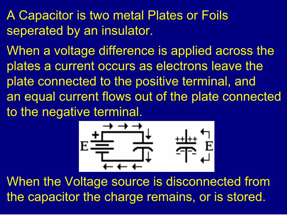
A Capacitor is two metal Plates or Foilsseperated by an insulator.
When a voltage difference is applied across theplates a current occurs as electrons leave theplate connected to the positive terminal, andan equal current flows out of the plate connectedto the negative terminal.
When the Voltage source is disconnected fromthe capacitor the charge remains, or is stored.

Connecting a volt meter or a resistive load willprovide a current path and the capacitor willdischarge at a rate determined by the size ofthe capacitor, and the resistance of the load.
The product of Capacitance and Resistance is called the Time Constant.
TC = R x C
Where TC is in seconds, R in Ohms, and C isin Farads.

Time ConstantThe time required to charge through aresistance to 63.2 % of an appliedvoltage, or discharge through thatresistance to 36.8% of the fully chargedvoltage.
Full Charge or full Discharge takes 5Time Constants.

CapacitanceCapacity is measured in Farads, in honour ofMichael Faraday.
A 1 Farad Capacitor will store 1 Coulomb at aPotential of 1 volt.
While Super and Ultra Capacitors in Farad sizesare now common, smaller sizes are practical foraudio and radio circuits. You will see:
microfarad F, 1/1,000,000F 1-6
nanofarad nF, 1/1,000,000,000 1-9
picofarad pF, 1/1,000,000,000,000 1-12
The micro-microfarad (mmf) of old is now the picofarad, not the nanofarad!

This forest of electrolytic capacitors is in the power supplysection, and includes:
2700F 10V, 560F 35V 100F 35V, 1000F 10V
220F 10V, Note that electrolytic capacitors are polarized, with a positiveand a negative lead. The negative lead is always marked.

Capacitor FactorsArea: A
The area of the plates of a capacitor directly effect the amount of capacity.
Separation: d
The distance between the plates inversely effects the amount of capacity.
Dielectric Constant: Є
The electrostatic density of the
material between the plates
directly effects the capacity.
C=ϵAd

Dielectric ConstantDifferent insulating materials have a different impact upon the amount of capacitance that an area and separation will create.
Vacuum = 1 Air = 1.0006 Teflon = 2.1
Paper (dry) = 2.2 - 3.5 Polystyrene = 2.6
Mylar = 3 Polycarbonate = 3 Transil Oil = 4
Pyrex = 4.7 Mica = 5.5 - 9.3 Porcelain = 5.5
Steatite = 5.8 Barium Titanate = 1250
Perovskite Ceramic CaCu3Ti4O12 = 10 000

Capacitors in ParallelConnecting Capacitors
in Parallel simply
Adds their Areas.
Add Capacitor Values.
eg: 100F + 50F = 150F
and: 12nF + 220pF = 12.22nF
and 1.5F + 0.47F = 1.97F
and 3.3nF + 680pF + 820pF = 4.8nF

Voltage Ratings of Parallel CapsParallel Circuits sharea common voltage.
All capacitors must havea voltage rating higher thanthe applied voltage.
This rating may be the same for all capacitors, orthey may be different, so long as the lowestrating is higher than the applied voltage.
eg: 10F63V + 22F36V + 100F25V might be connected to an 18 volt circuit.

Capacitors in Series
Capacitors connected in Series Add the spacing between Plates. This reduces the total amount of capacitance.If the capacitors are of equal value, the voltage across each capacitor is equal.Total capacitance is always smaller than the value of the smallest capacitor.For Two: For Three or More:
CT=C1×C2C1+C 2
1CT
=1C1
+1C2
+1C3
+. ..

Equal Capacitors In SeriesEqual capacitors in series reducecapacitance by the number ofcapacitors.
Five 680F capacitors create a680 / 5 = 136F capacitor.
Their Separations Add, and sodo their equal voltage ratings.
Five 300 Volt capacitors can becharged to 300 x 5 = 1500 Volts

Unequal Capacitors in SeriesMust Use the Series Capacitor Equation.
1/47nF = 21,276,595
1/68nF = 14,705,882
1/27nF = 37,037,037
1/56nF = 17,857,143
1/33nF = 30,303,030 ________________________________
1/CT = 121,179,687 so C = 8.25nF
1CT
=1
47 nF+
168nF
+1
27 nF+
156 nF
+1
33nF

Voltage Division of UnequalCapacitorsThe flow of charge in a series capacitor circuit isequal everywhere.
Capacitor Voltage is inversely proportional to its Capacitance.
Small capacitors will have high voltage.
Large capacitors will have low voltage.
V X=CTC X
×V T
V 1=C2C1
×V 2
V=QC

Voltage Division of Unequal Capacitors
V X=CTC X
×V T
V 1000=319.7 μF1000 μF
×20V=6 .4V
CT=1000μF×470 μF1470μF
=319 .7 μF
V 470=319.7 μF470 μF
×20V=13 .6V
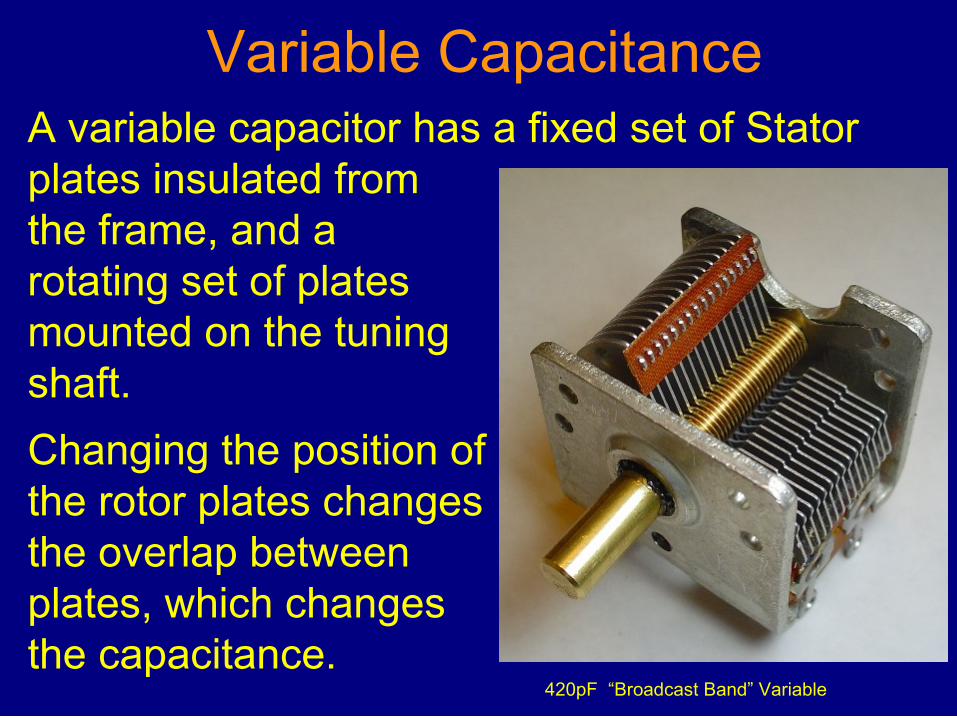
Variable CapacitanceA variable capacitor has a fixed set of Statorplates insulated fromthe frame, and arotating set of platesmounted on the tuningshaft.
Changing the position ofthe rotor plates changesthe overlap betweenplates, which changesthe capacitance.
420pF “Broadcast Band” Variable

Variable Transmitting Capacitors designed for High Voltageand High Current in a Power Amplifier or Tuner.
Top is a 65-850pF 3KV Air Variable.Bottom is a 10-1000pF 5KV Ceramic Vacuum Variable.

IMPEDANCE
The AC Resistance
Capacitive Reactance
Inductive Reactance
Capacitive Reactance
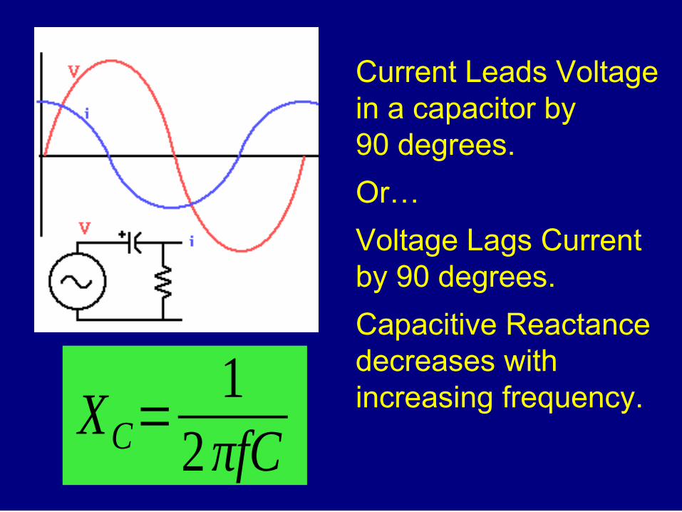
XC=1
2πfC
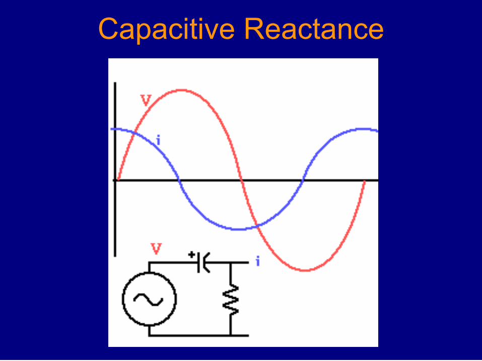
Current Leads Voltagein a capacitor by90 degrees.
Or…
Voltage Lags Currentby 90 degrees.
Capacitive Reactancedecreases withincreasing frequency.
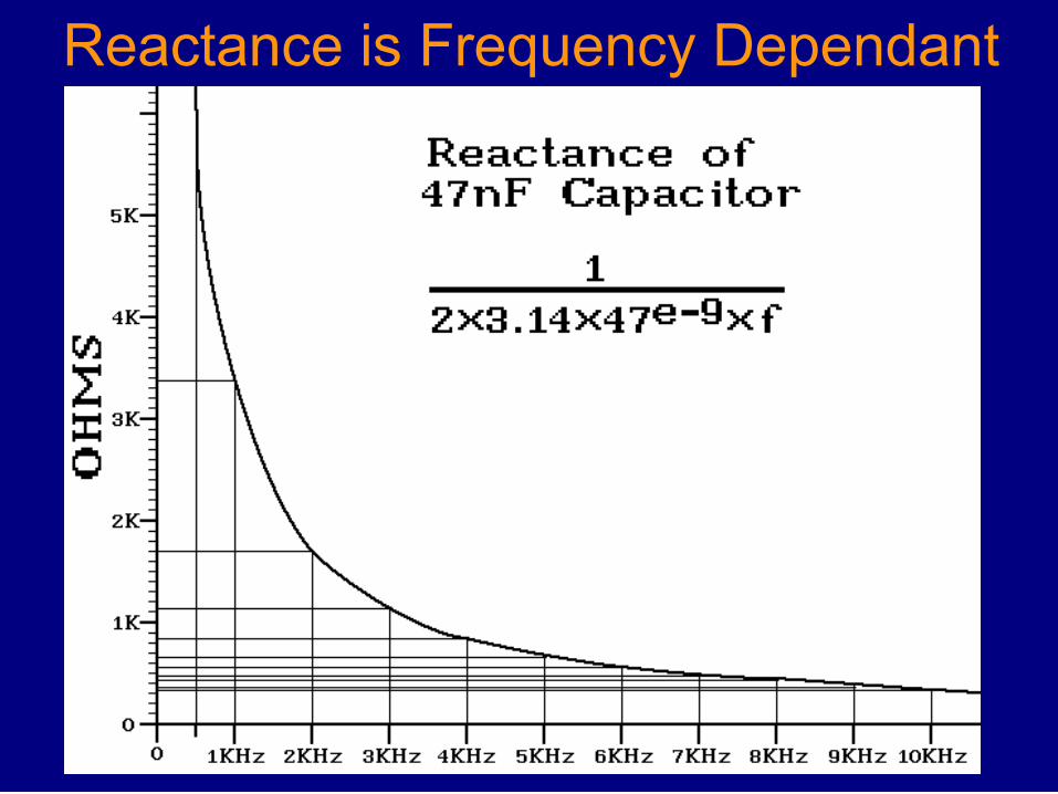
Reactance is Frequency Dependant
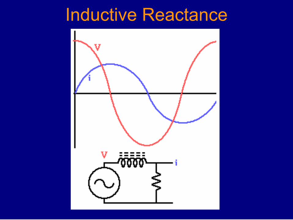
Inductive Reactance

Current Lags Voltage in an Inductor by 90 degrees,
Or:Voltage Leads Current by 90 degrees.
Inductive Reactance (XL) increases with increasing frequency.
X L=2 πfL

Reactance Varies with Frequency

IMPEDANCEReal circuits contain both Resistance & Reactance.
Current in a resistor is in phase with the applied voltage.
Current in a Reactance (a capacitor or coil) is either leading or lagging.
Combining Resistance and Reactance creates an Impedance in which the current leads or lags voltage by less than 90 degrees.

Impedance
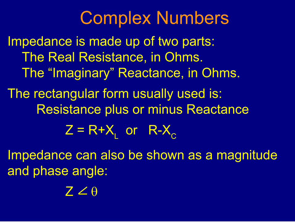
Complex NumbersImpedance is made up of two parts:
The Real Resistance, in Ohms.The “Imaginary” Reactance, in Ohms.
The rectangular form usually used is:Resistance plus or minus Reactance
Z = R+XL or R-X
C
Impedance can also be shown as a magnitudeand phase angle:
Z
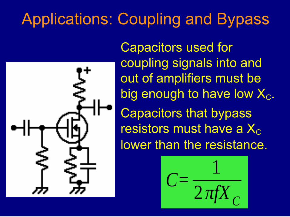
Applications: Coupling and Bypass
Capacitors used for coupling signals into and out of amplifiers must be big enough to have low XC.
Capacitors that bypass resistors must have a XC lower than the resistance.
C=1
2πfXC

Applications: Filtering
A large capacitor is used to store charge in a power supply.
The rectified power is at 60Hz, line frequency.
What is the XC of the filter capacitor?
XC=1
2πfC
XC=1
2π 60×1−3=
1
377×1−3=2.65Ω

Applications: Filtering
In a switch mode power supply the frequency is 50KHz.
What is the XL of the choke coil?
What is the XC of the filter capacitor?
XC=1
2π 503×1−3=1
314159×1−3=3 .2mΩ
X L=2 πfL=2π 50000 L314159×0.013141 .6Ω

Applications: Separating Frequencies
A Woofer can’t handle frequencies over 1KHz.
A Tweeter can’t handle frequencies under 1KHz.
A Cross Over Network blocks high frequencies from the woofer and low frequencies from the tweeter.