CAPACITIVE VOLTAGE TRANSFORMERS AND COUPLING …
8
Instrument transformers | High voltage CAPACITIVE VOLTAGE TRANSFORMERS AND COUPLING CAPACITORS _DDB/DFK Series _DDN/DFN Series
Transcript of CAPACITIVE VOLTAGE TRANSFORMERS AND COUPLING …
Instrument transformers | High voltage
CAPACITIVE VOLTAGE TRANSFORMERS AND COUPLING CAPACITORS
_DDB/DFK Series_DDN/DFN Series

39Instrument transformers | High voltage
Capacitive voltage transformers are designed to provide a scaled down replica of the voltage in the HV line and isolate the measuring instruments, meters, relays, etc., from the high voltage power circuit.
They enable transmission of high frequency signals through the high voltage (HV) lines.
Coupling capacitors are only used for coupling high frequency communication signals, making them equivalent to the capacitive part of a CVT.
CAPACITIVE VOLTAGE TRANSFORMERS AND COUPLING CAPACITORS
APPLICATIONSVoltage input to diff erent types of protection relays.
Ideal for installation at metering points due to its very high accuracy class and extremely steady capacitance.
Transmission of high-frequency signals through the high voltage lines (PLC).
Helps to reduce voltage peaks in the line.
Harmonic measurement in conjunction with PQSensor®.
Examples of applications:
1. Revenue metering.
2. Protection for high voltage lines and substations.
M
3. Transmission of high frequency signals.
Instrument transformers | High voltage40
1
3
5
6
7
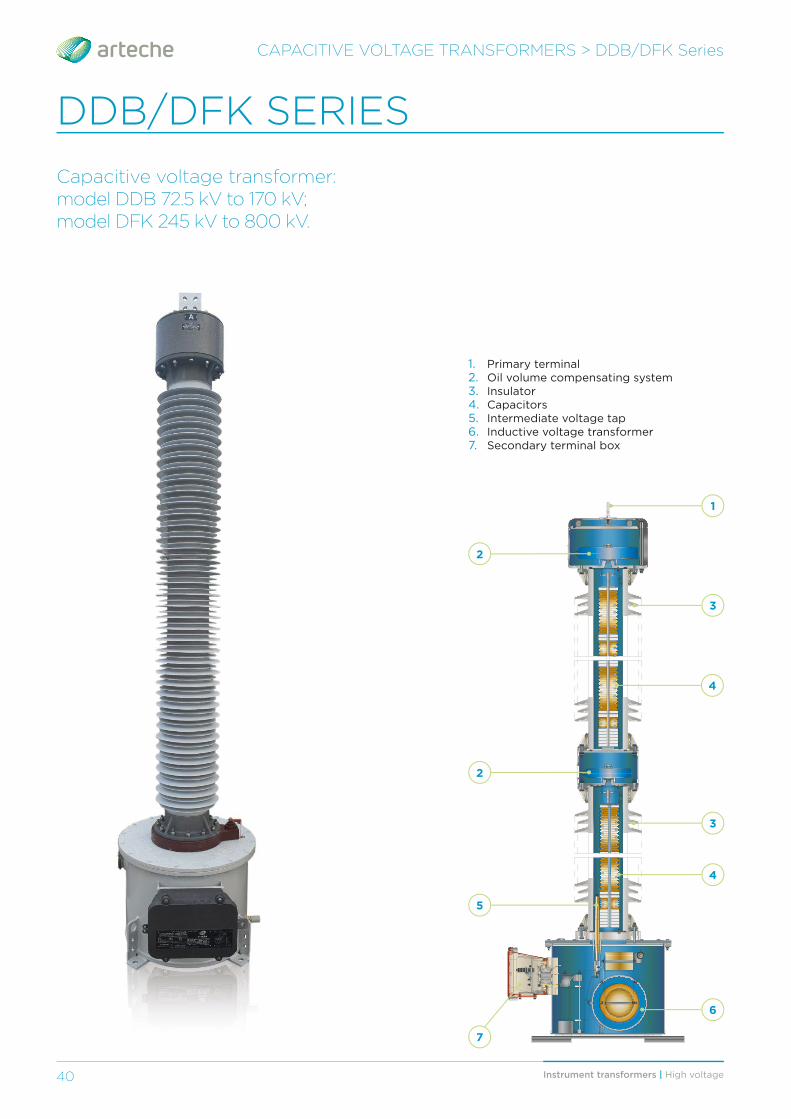
1. Primary terminal2. Oil volume compensating system3. Insulator4. Capacitors5. Intermediate voltage tap6. Inductive voltage transformer7. Secondary terminal box
CAPACITIVE VOLTAGE TRANSFORMERS > DDB/DFK Series
DDB/DFK SERIES
Capacitive voltage transformer:model DDB 72.5 kV to 170 kV;model DFK 245 kV to 800 kV.
2
2
3
4
4

41Instrument transformers | High voltage 41
CAPACITIVE VOLTAGE TRANSFORMERS > DDB/DFK Series
› High stability of capacitance, and therefore of accuracy, steady for the operational life of the equipment, with maximum reliability.
› Up to 4 secondary windings with or without taps, with metering, protection, or dual function.
› Reliable ferroresonance suppres.sion system that does not aff ect transient response or accuracy.
› Robust mechanical strength.
› Excellent response under extreme environmental conditions: Temperatures from -60°C up to +60°C, high altitudes, seismic hazard areas, violent winds, etc.
› Maintenance-free throughout their complete lifespan of more than 30 years. Only periodic monitoring is recommended.
› Oil sampling valve and EMU oil level indicator for monitoring.
› Hermetically sealed to guarantee complete water tightness with the minimum volume of oil. Each unit is tested individually.
› Metallic oil level compensating system that eff ectively regulates changes in oil volume mainly caused by temperature.
› Offi cially homologated in-house testing facilities.
› Quality management system certifi cations: ISO 9001, ISO 14001 and OHSAS 18001.
› Each unit is routine tested following applicable standards.
CHARACTERISTICS
Capacitive voltage transformers consist of a number of capacitors connected in series on top of a tank in which the electromagnetic unit (EMU) is housed. The EMU includes and inductive transformer (5), a series reactor (8) and other auxiliary elements. These capacitors form a voltage divider (2, 3) between the high voltage terminal (1) and the high frequency terminal (4).
The capacitors, impregnated with high grade dielectric oil, are housed within one or more insulators. Each of them forms an hermetically sealed independent unit, with a very stable capacitance over time.
The high frequency terminal (4) for the PLC signal comes out of one side through a piece of resin that separates the capacitive unit from the inductive voltage transformer.
The medium voltage inductive voltage transformer is immersed in mineral oil and housed inside an hermetically sealed metallic tank.
The secondary terminals are located inside the secondary terminal box (7) enabling connection; suffi cient space is available to install protection elements such as fuses or circuit breakers.
DESIGN AND MANUFACTURING
1. Primary terminal2. Capacitors (C1)3. Capacitors (C2)4. High frequency terminal5. Inductive voltage transformer6. Ferroresonance suppression circuit7. Secondary terminal box8. Compensating reactor
2
1
3
5
4
6
6
7
8
› Complete type tests reports following international standards.
› Compliance to any international or domestic standards.
› Environmentally friendly. The materials used for construction are recyclable and resistant to the elements. Its advanced design adheres to environmental regulations using high-quality insulating oils, free of PCBs.
› Reduced size due to a compact design that is easy to transport, store and install, and which reduces visual impact.
OPTIONS:
› Carrier accessories for HF signal transmission.
› Line trap mounted on top of the CVT.
› EMU grounding switch.
› PQSensor® for HF harmonic measurement.
› Porcelain or polymeric insulators.
› Sealable secondary terminals.
› Diff erent cable glands and accessories.
› Wide range of capacitance values available.
› Wide range of primary and secondary terminals.
› Secondary protection devices inside the terminal box (fuses, MCBs…).

Instrument transformers | High voltage42
CAPACITIVE VOLTAGE TRANSFORMERS > DDB/DFK Series
RANGEThis series is named with the letters DDB or DFK followed by 2 or 3 numbers indicating the maximum service voltage for which they have been designed.
The table on the next page shows the range currently manufactured by ARTECHE. These characteristics are merely indicative. ARTECHE can manufacture these transformers to comply with any domestic or international standard.
Secondary windings for:
› Protection: all possible types.
› Metering: accuracy classes for any metering/billing need (including high accuracy class 0.1 / 0.15 with extended range in current).
Number of secondary windings: up to 4 secondary windings are possible in a single device.
H
A
A
43Instrument transformers | High voltage 43
CAPACITIVE VOLTAGE TRANSFORMERS > DDB/DFK Series
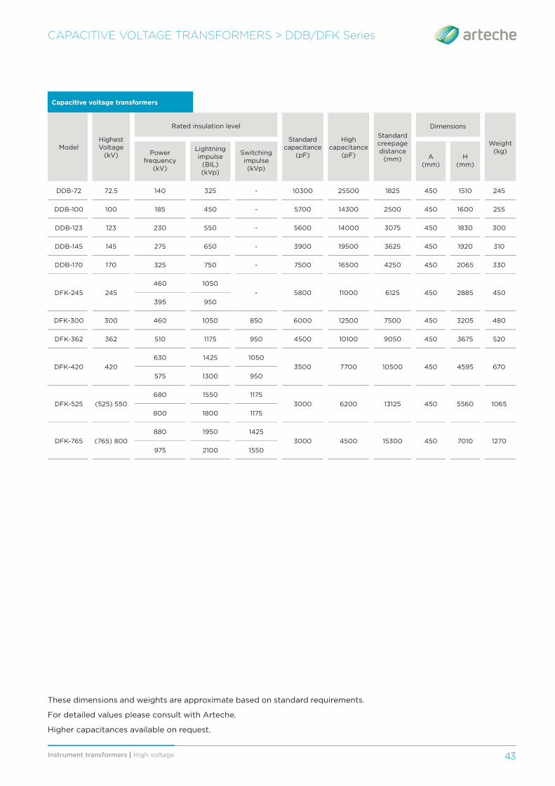
Capacitive voltage transformers
ModelHighest Voltage
(kV)
Rated insulation level
Standard capacitance
(pF)
High capacitance
(pF)
Standard creepage distance
(mm)
Dimensions
Weight (kg)Power
frequency (kV)
Lightning impulse
(BIL) (kVp)
Switching impulse (kVp)
A(mm)
H(mm)
DDB-72 72.5 140 325 - 10300 25500 1825 450 1510 245
DDB-100 100 185 450 - 5700 14300 2500 450 1600 255
DDB-123 123 230 550 - 5600 14000 3075 450 1830 300
DDB-145 145 275 650 - 3900 19500 3625 450 1920 310
DDB-170 170 325 750 - 7500 16500 4250 450 2065 330
DFK-245 245
460 1050
- 5800 11000 6125 450 2885 450
395 950
DFK-300 300 460 1050 850 6000 12500 7500 450 3205 480
DFK-362 362 510 1175 950 4500 10100 9050 450 3675 520
DFK-420 420
630 1425 1050
3500 7700 10500 450 4595 670
575 1300 950
DFK-525 (525) 550
680 1550 1175
3000 6200 13125 450 5560 1065
800 1800 1175
DFK-765 (765) 800
880 1950 1425
3000 4500 15300 450 7010 1270
975 2100 1550
These dimensions and weights are approximate based on standard requirements.
For detailed values please consult with Arteche.
Higher capacitances available on request.

Instrument transformers | High voltage44
Coupling capacitor: model DFN up to 800 kV;model DDN up to 170 kV.
COUPLING CAPACITORS > DDN/DFN Series
DDN/DFN SERIES
Coupling capacitors consist of a number of capacitors connected in series. The capacitors, impregnated with high grade dielectric oil, are housed in one or more insulators. Each of them forms an hermetically sealed independent unit, with a very stable capacitance over time.
DESIGN AND MANUFACTURINGThe high frequency terminal for the PLC signal comes out from the bottom of the unit and it is connected to the HF carrier accessories.

45Instrument transformers | High voltage 45
COUPLING CAPACITORS > DDN/DFN Series
› Carrier accessories for HF signal transmission.
› Robust mechanical strength.
› Excellent response under extreme environmental conditions: Temperatures from -60°C up to +60°C, high altitudes, seismic hazard areas, violent winds, etc.
› Maintenance-free throughout their complete lifespan of more than 30 years. Only periodic monitoring is recommended.
› Hermetically sealed to guarantee complete water tightness with the minimum volume of oil. Each unit is tested individually.
› Metallic oil level compensating system that eff ectively regulates changes in oil volume mainly caused by temperature.
› Offi cially homologated in-house testing facilities.
› Quality management system certifi cations: ISO 9001, ISO 14001 and OHSAS 18001.
› Each unit is routine tested following applicable standards.
CHARACTERISTICS
RANGEThis series is named with the letters DDN or DFN followed by 2 or 3 numbers indicating the maximum service voltage for which they have been designed.
› Complete type tests reports following international standards.
› Compliance to any international or domestic standards.
› Environmentally friendly. The materials used for construction are recyclable and resistant to the elements. Its advanced design adheres to environmental regulations using high-quality insulating oils, free of PCBs.
› Reduced size due to a compact design that is easy to transport, store and install, and which reduces visual impact.
OPTIONS:
› Line trap mounted on top of the Coupling Capacitor.
› Porcelain or polymeric insulators.
› Wide range of capacitance values available.
› Wide range of primary terminals.
These dimensions and weights are approximate based on standard requirements.For detailed values please consult with Arteche. Higher capacitances available on request.
Coupling capacitors
ModelHighest Voltage
(kV)
Rated insulation level
Standard capacitance
(pF)
High capacitance
(pF)
Standard creepage distance (mm)
Dimensions
Weight (kg)Power
frequency(kV)
Lightning impulse
(BIL) (kVp)
Switching impulse (kVp)
A(mm)
H(mm)
DDN-72 72.5 140 325 - 10300 25500 1825 450 1235 115
DDN-100 100 185 450 - 5700 14300 2500 450 1325 120
DDN-123 123 230 550 - 5600 14000 3075 450 1585 145
DDN-145 145 275 650 - 3900 19500 3625 450 1675 150
DDN-170 170 325 750 - 7500 16500 4250 450 1805 170
DFN-245 245 460 1050 - 5800 11000 6125 450 2625 255
DFN-300 300 460 1050 850 6000 12500 7500 450 2945 305
DFN-362 362 510 1175 950 4500 10100 9050 450 3415 345
DFN-420 420630 1425 1050
3500 7700 10500 450 4335 495575 1300 950
DFN-525(525) 550
680 1550 11753000 6200 13125 450 5300 890
800 1800 1173
DFN-765(765) 800
880 1950 14253000 4500 15300 450 6760 1095
975 2100 1550
The table shows the range currently manufactured by ARTECHE. These characteristics are merely indicative. ARTECHE can manufacture these transformers to comply with any domestic or international standard.
H
A
A