Capacitance and Capacitive Reactance - Payam Zarbakhshpayamzarbakhsh.com/images/PDF/power5.pdf ·...
13
Capacitance and Capacitive Reactance
Transcript of Capacitance and Capacitive Reactance - Payam Zarbakhshpayamzarbakhsh.com/images/PDF/power5.pdf ·...

Capacitance and Capacitive Reactance

Since a voltage V is applied to a pair of conductors separated by a dielectric (air), charges of equal magnitude but opposite sign will accumulate on the conductors:
q CV
Where C is the capacitance between the pair of conductors.
In AC power systems, a transmission line carries a time-varying voltagedifferent in each phase. This time-varying voltage causes the changes incharges stored on conductors. Changing charges produce a changingcurrent, which will increase the current through the transmission line andaffect the power factor and voltage drop of the line. This changing currentwill flow in a transmission line even if it is open circuited.

The capacitance of the transmission line can be found using the Gauss’s law:
A
D dA q where A specifies a closed surface; dA is the unit vector normal to the surface; q is the charge inside the surface; D is the electric flux density at the surface:
D Ewhere E is the electric field intensity at that point; is the permittivity of the material:
0r Relative permittivity of the material
The permittivity of free space 0 = 8.8510-12 F/m
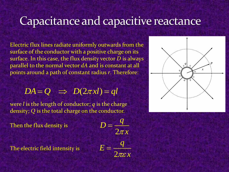
Electric flux lines radiate uniformly outwards from the surface of the conductor with a positive charge on its surface. In this case, the flux density vector D is always parallel to the normal vector dA and is constant at all points around a path of constant radius r. Therefore:
(2 )DA Q D xl ql
were l is the length of conductor; q is the charge density; Q is the total charge on the conductor.
Then the flux density is2
qD
x
The electric field intensity is2
qE
x
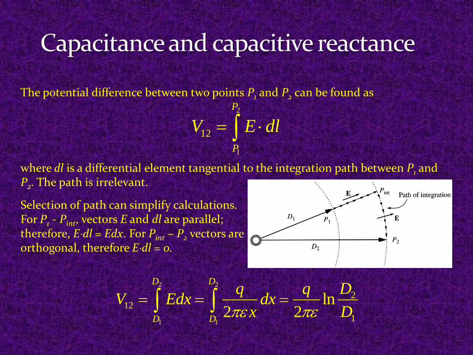
The potential difference between two points P1 and P2 can be found as
2
1
12
P
P
V E dl
where dl is a differential element tangential to the integration path between P1 and P2. The path is irrelevant.
Selection of path can simplify calculations.For P1 - Pint, vectors E and dl are parallel; therefore, Edl = Edx. For Pint – P2 vectors are orthogonal, therefore Edl = 0.
2 2
1 1
212
1
ln2 2
D D
D D
Dq qV Edx dx
x D
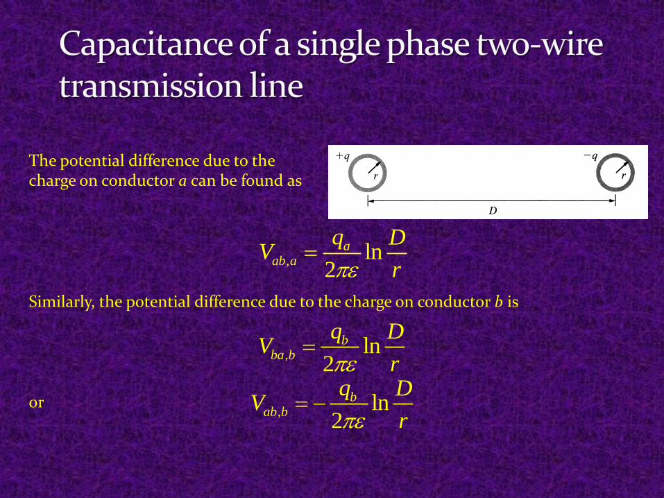
The potential difference due to the charge on conductor a can be found as
, ln2
aab a
q DV
r
Similarly, the potential difference due to the charge on conductor b is
, ln2
bba b
q DV
r
, ln2
bab b
q DV
r or
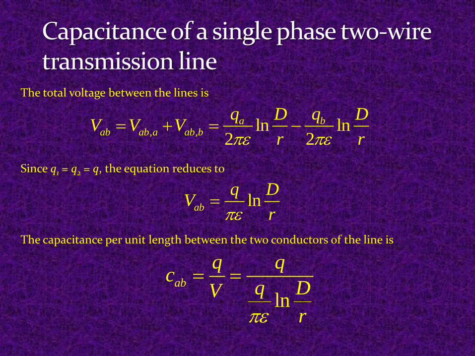
The total voltage between the lines is
, , ln ln2 2
a bab ab a ab b
q qD DV V V
r r
Since q1 = q2 = q, the equation reduces to
lnab
q DV
r
The capacitance per unit length between the two conductors of the line is
lnab
q qc
q DV
r
lnabc
D
r
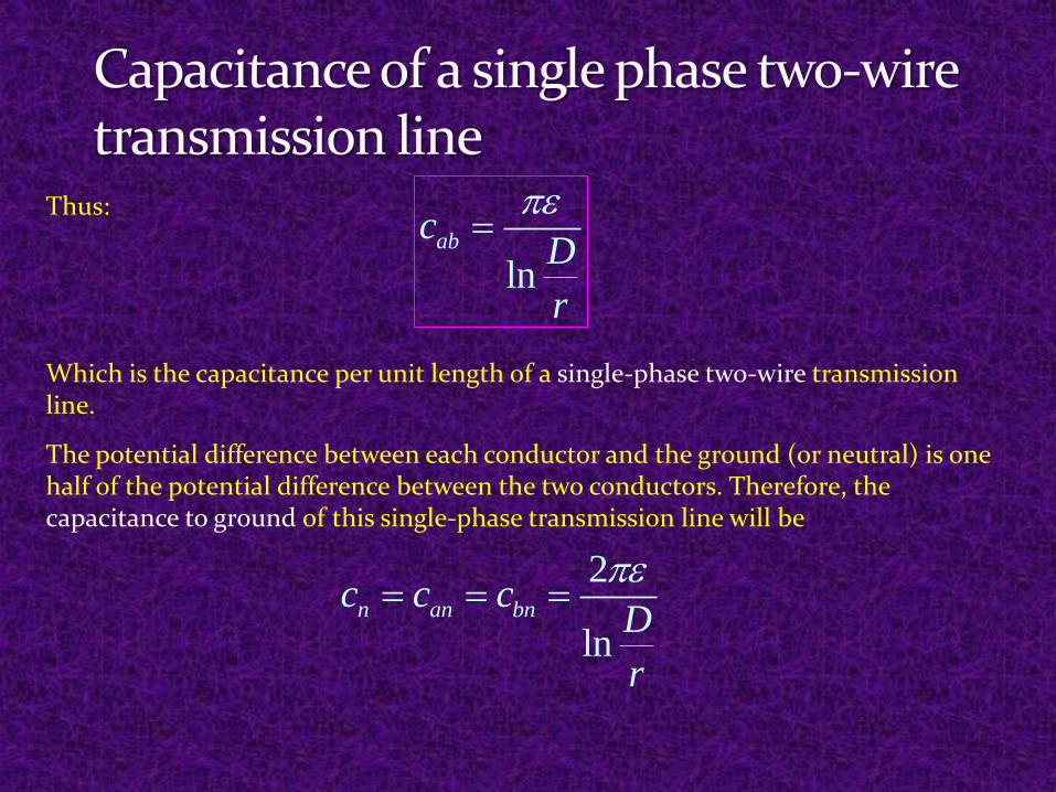
Thus:
Which is the capacitance per unit length of a single-phase two-wire transmission line.
The potential difference between each conductor and the ground (or neutral) is one half of the potential difference between the two conductors. Therefore, the capacitance to ground of this single-phase transmission line will be
2
lnn an bnc c c
D
r

Analysis of the equation shows that:
1. The greater the spacing between the phases of a transmission line,the lower the capacitance of the line. Since the phases of a high-voltage overhead transmission line must be spaced further apart toensure proper insulation, a high-voltage line will have a lower capacitancethan a low-voltage line. Since the spacing between lines in buried cablesis very small, shunt capacitance of cables is much larger than thecapacitance of overhead lines. Cable lines are normally used for shorttransmission lines (to min capacitance) in urban areas.
2. The greater the radius of the conductors in a transmission line, thehigher the capacitance of the line. Therefore, bundling increases thecapacitance. Good transmission line is a compromise among therequirements for low series inductance, low shunt capacitance, and alarge enough separation to provide insulation between the phases.

The shunt capacitive admittance of a transmission line depends on both the capacitance of the line and the frequency of the power system. Denoting the capacitance per unit length as c, the shunt admittance per unit length will be
2Cy j c j fc The total shunt capacitive admittance therefore is
2C CY y d j fcd
where d is the length of the line. The corresponding capacitive reactance is the reciprocal to the admittance:
1 1
2C
C
Z jY fcd
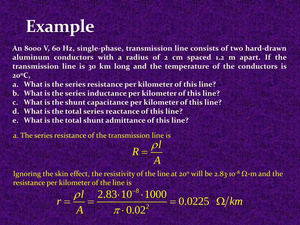
An 8000 V, 60 Hz, single-phase, transmission line consists of two hard-drawnaluminum conductors with a radius of 2 cm spaced 1.2 m apart. If thetransmission line is 30 km long and the temperature of the conductors is200C,a. What is the series resistance per kilometer of this line?b. What is the series inductance per kilometer of this line?c. What is the shunt capacitance per kilometer of this line?d. What is the total series reactance of this line?e. What is the total shunt admittance of this line?
a. The series resistance of the transmission line is
lR
A
Ignoring the skin effect, the resistivity of the line at 200 will be 2.8310-8 -m and the resistance per kilometer of the line is
8
2
2.83 10 10000.0225
0.02
lr km
A
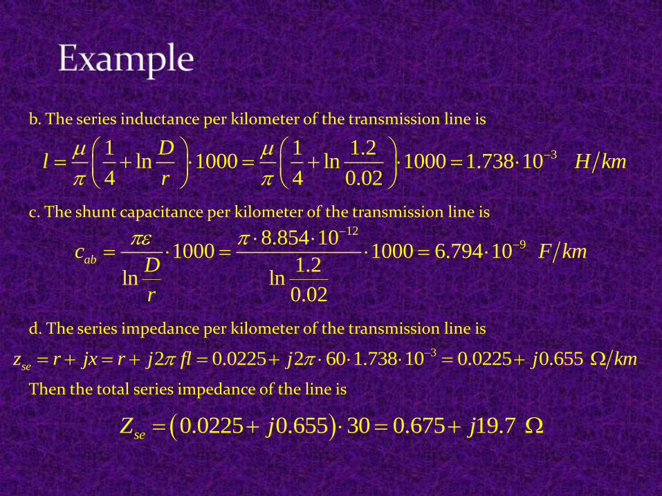
b. The series inductance per kilometer of the transmission line is
31 1 1.2ln 1000 ln 1000 1.738 10
4 4 0.02
Dl H km
r
c. The shunt capacitance per kilometer of the transmission line is12
98.854 101000 1000 6.794 10
1.2ln ln
0.02
abc F kmD
r
d. The series impedance per kilometer of the transmission line is
32 0.0225 2 60 1.738 10 0.0225 0.655sez r jx r j fl j j km
Then the total series impedance of the line is
0.0225 0.655 30 0.675 19.7seZ j j

e. The shunt admittance per kilometer of the transmission line is
9 62 2 60 6.794 10 2.561 10Cy j fc j j S m
The total shunt admittance will be
6 52.561 10 30 7.684 10seY j j S
The corresponding shunt capacitive reactance is
5
1 113.0
7.684 10sh
sh
Z j kY j