UNUSUAL FISH OFF THE SUFFOLK COAST: ATLANTIC BONITO SARDA SARDA AND GREATER WEEVER TRACHINUS DRACO

Canal Falls

Definition and Location of Canal Falls Whenever the available natural ground slope
is steeper than the designed bed slope of thechannel, the difference is adjusted byconstructing vertical 'falls' or 'drops' in thecanal bed at suitable intervals, as shown inFig. 12.1.
Such a drop in a natural canal bed will not bestable and, therefore, in order to retain this
Proper location: The location of a fall in a canal depends upon the topography of the
country through which the canal is passing. In case of the main canal, whichdoes not directly irrigate any area, the site of a fall is determined byconsiderations of economy in 'cost of excavation and filling' versus 'cost offall'.
By providing a larger drop in one step, the quantity of unbalanced earthwork increases, but at the same time, the number of fall reduces. Aneconomy between these two factors has to be worked out before decidingthe locations and extent of falls.
drop, a masonry structure is constructed. Such a pucca structure is called a canal fall or a canal drop.

In case of branch canals and distributaries channels, the falls are locatedwith consideration to commanded area. The procedure is to fix the FSLrequired at the head of the off-taking channels and outlets and mark themon the L-section of the canal. The FSL of the canal can then be marked, asto cover all the commanded points, thereby deciding suitable locations forfalls in canal FSL, and hence, in canal beds.
Types of FallsVarious types of falls have been designed and tried since the inception of theidea of 'falls construction' came into being. The important types of such falls,which were used in olden days and those which are being used in modern days,are described below:(1) Ogee Falls: The 'Ogee type fall' was constructed in olden days on projectslike Ganga canal. The water was gradually led down by providing convex andconcave curves, as shown in Fig. 12.2.The performance of such an ogee fall was found to have the following majordefects:(i) There was heavy draw-down on the upstream side, resulting in lower
depths, higher velocities and consequent bed erosion. Draw-down wouldalso affect the supply in a distributaries, situated just upstream of fall.
(ii) Due to smooth transition, the kinetic energy of the flow was not at alldissipated, causing erosion of downstream bed and banks.

(iii) A raised crest was soon added to restrict the draw-down and a longprotection was provided on the downstream side. Later, it was convertedinto a much better type of fall, called a Vertical Impact type. The notchescould be designed to maintain the normal water depth in the upstreamchannel at any two discharges, as the variation at intermediate values issmall. Hence, the depth discharge relationship of the channel remainspractically unaffected by the introduction of the fall. In other words, therewould neither be drawdown nor heading up of water, as the channelapproaches the fall. These fall remained quite popular, till simpler,economical, and better modern falls were developed.

VI) Trapezoidal Notch Fall
The enclosed figure shows the different views ofTrapezoidal Notch Fall. In this type a body orfoundation wall across the channel consisting ofseveral trapezoidal notches between the side piers andthe intermediate piers is constructed as shown inenclosed figure.
The sills of the notches are kept at U/S bed level of thecanal. The body wall is made of concrete. Animpervious floor is provided to resist the scouringeffect of falling water.
U/S and D/S side of the fall is protected by stonepitching, finished by cement grouting.

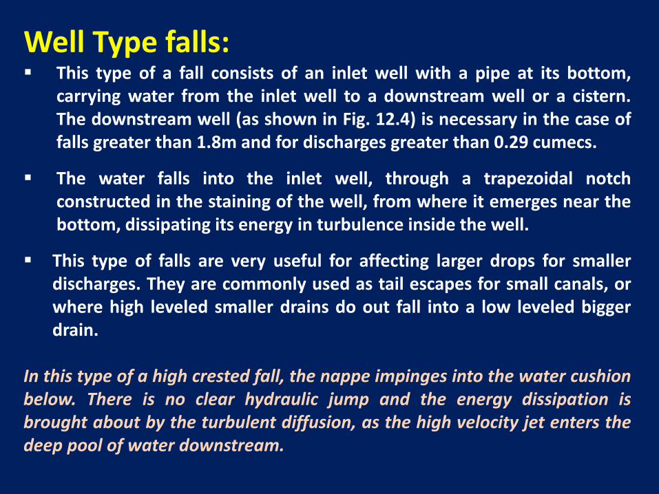
Well Type falls: This type of a fall consists of an inlet well with a pipe at its bottom,
carrying water from the inlet well to a downstream well or a cistern.The downstream well (as shown in Fig. 12.4) is necessary in the case offalls greater than 1.8m and for discharges greater than 0.29 cumecs.
The water falls into the inlet well, through a trapezoidal notchconstructed in the staining of the well, from where it emerges near thebottom, dissipating its energy in turbulence inside the well.
This type of falls are very useful for affecting larger drops for smallerdischarges. They are commonly used as tail escapes for small canals, orwhere high leveled smaller drains do out fall into a low leveled biggerdrain.
In this type of a high crested fall, the nappe impinges into the water cushionbelow. There is no clear hydraulic jump and the energy dissipation isbrought about by the turbulent diffusion, as the high velocity jet enters thedeep pool of water downstream.


9
III) Vertical Fall
Enclosed figures (a & b) shows the simple vertical and Sarda types
canal falls, respectively.
In Figure-’a’ the U/S canal bed level is at the level of U/S curtain
wall and in Figure-’b’ canal U/S bed is below the crest of curtain
wall.
In both cases a cistern is formed to act as water cushion. Floor is
made of concrete U/S and D/S side stone pitching with cement
grouting is provided.

10

(6) Straight Glacis Falls: In this type of a modern fall, a straight glacis, (generally sloping 2:1)
is provided after a raised crest (see Fig, 12.6). The hydraulic jump ismade to occur on the glacis, causing sufficient energy dissipation.
This type of falls give very good performance if not flumed, althoughthey may be flumed for economy. They are suitable up to 60 comicsdischarge and 1.5m drop.

(7) Montague Type Falls: The energy dissipation on a straight glacis remain incomplete
due to vertical component of velocity remaining unaffected. Animprovement in energy dissipation may be brought about inthis type of fall (see Fig, 12.7) by replacing the straight glacisby a parabolic glacis, commonly known as Monotague Profile.

4yX U Y
g

(8) Inglis Falls or Baffle Falls: A straight glacis type fall when added with a baffle platform and
a baffle wall as shown in Fig. 12.8, was developed by Englis, andis called Englis Fall or Baffle Fall. They are quite suitable for alldischarges and for drops of more than 1.5m. They can be flumedeasily as to effect economy.
The baffle wall is provided at a calculated height and a calculateddistance from the toe of the glacis, so as to ensure the formationof the jump on the baffle platform, as shown in Fig. 12.8.

Comparison of Different types of Falls:
Vertical drop falls are quite suitable for discharges upto 15 comicsand drops upto 1.5 meters. But this type of fall should not beflumed.
For “straight Glacis” type falls, the conclusion was, that they worksatisfactorily for all conditions, if unflumed; but in that case theybecome costly. Even then, they can be adopted suitably fordischarges upto 60 cumecs and drops upto 1.5 metres, and caneven be flumed.
Baffle fall or English Fall may be used for all discharges when dropis more than 1.5 meters. This type of fall functions verysatisfactorily, either flumed or unflume4d, so long as it isundrowned.
Well type falls are suitable and economical for high drops andvery low discharges. They can hence be easily used, as tail escapesof small channels.

Meter and Non-Meter Falls:
Meter falls are those which can be used to measure thedischarge of the canal. If the discharge cannot be measuredaccurately at the site of the fall, then it is called a non-meterfall.
Vertical drop fall is not suitable as a meter due to theformation of partial vacuum under the nappe. Glacis typefall is quite suitable as a metering device.
Since a sharp crest does not give a constant coefficient ofdischarge with varying heads, while a broad crest does soreasonably; a fall to be used as meter must be provided witha broad crest. Generally, a flumed glacis fall or a flumedbaffle fall, is used as meter, while an unflumed glacis fall isused as a non-meter fall.

Design of a Straight Glacis Fall1) Cistern Element:

2) Crest Length:
3) Crest Width:

4) Discharge Formula:
5) Crest Level:
6) Hump:

7) Upstream Protection:

8) Downstream Glacis:
9) Length and Thickness of Floor:
10) Downstream Protection:
11) Upstream Wing Walls:

12) Downstream Wing Walls
(1) Friction Blocks:
Roughening Devices or Energy Dissipators

(a) For Vertical Drop Fall
(b) For Glacis Fall

(2) Glacis Blocks:

Example 12.3
Solution
Adopt crest length


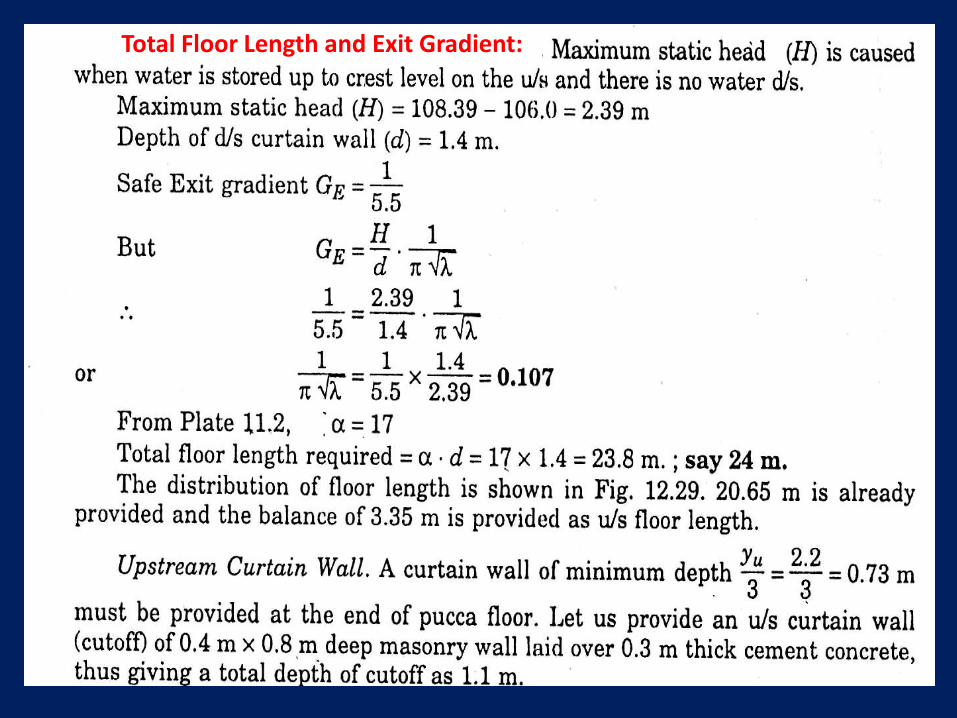
Total Floor Length and Exit Gradient:

Uplift Pressures:


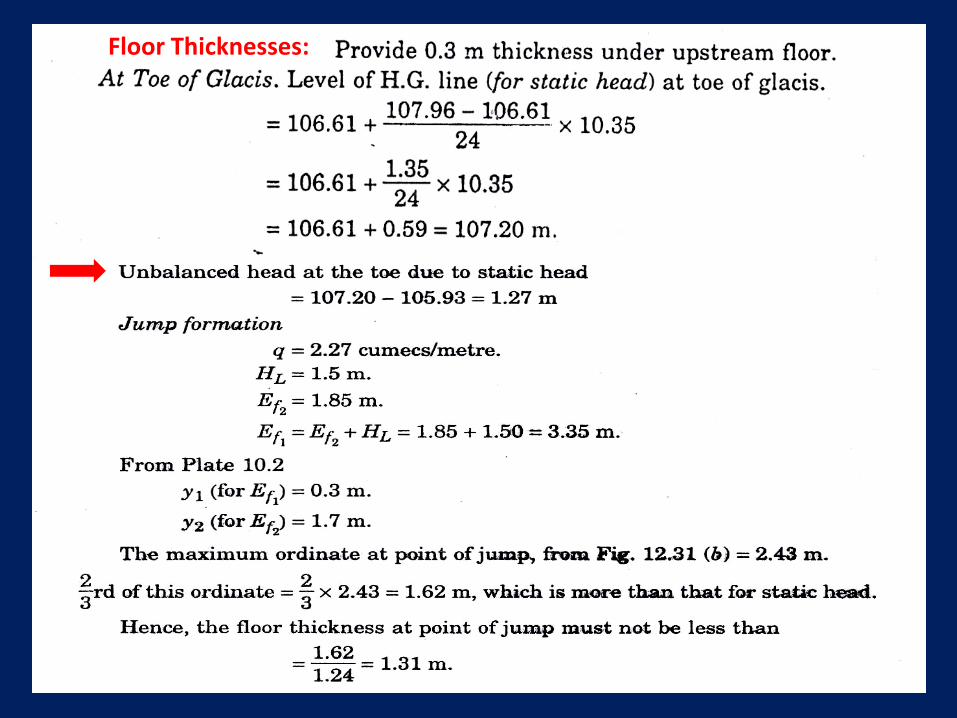
Floor Thicknesses: