
CANADIAN WATERWAYS NATIONAL MANOEUVRING … Navegables/eng-1.pdf · LIST OF FIGURES Figure 1:...
70
CANADIAN WATERWAYS NATIONAL MANOEUVRING GUIDELINES: CHANNEL DESIGN PARAMETERS
Transcript of CANADIAN WATERWAYS NATIONAL MANOEUVRING … Navegables/eng-1.pdf · LIST OF FIGURES Figure 1:...

CANADIAN WATERWAYS NATIONAL MANOEUVRING GUIDELINES:
CHANNEL DESIGN PARAMETERS


Produced by Waterways Development, Marine Navigation Services, Canadian Coast Guard, Fisheries and Oceans Canada
Revised June, 1999

INTRODUCTION In navigable waterways where the vessel traffic is expected to make use of the full water depth and width, it is necessary to ensure that a careful balance is achieved between the need to accommodate the user (thus maximising economic benefits to the industry) and the paramount need to maintain adequate safety allowances. This involves analyses and full account of the interrelations between the parameters of the vessels, the waterway and weather factors. In addition, other factors, such as frequency of siltation, maintenance requirements, availability of navigational aid, pilotage, dredgate disposal options (if dredging is considered), as well as economic and environmental impacts, all need to be considered. This document provides planners with a set of procedures to be used when determining waterway parameters required to provide efficient manoeuvrability with no less than minimum safety margins and allowances. Procedures are set forth for the determination of channel width, depth, side slope and curvature, as well as the alignment of channels. The guidelines have been developed for waterways utilized primarily by large traffic, such as tankers, general cargo and bulk carriers, and are not meant to replace more extensive analyses for the final channel design. As with the application of any guidelines, good judgement, experience and common sense will be required in their application. The methods are based upon the operational requirements for ships, and the aim is to provide the conceptual requirements for safe and efficient navigation. The design procedure for each element of waterway geometry is provided in order to enable the planner to optimize the design.

TABLE OF CONTENTS
1 — Input Parameters - Waterway Dimensions........................................... 1 1.1 Vessel .................................................................................................. 1 1.2 Waterway ............................................................................................. 1 1.3 Baseline Study Data ............................................................................... 1 1.4 Water Level........................................................................................... 2
2 — Width .................................................................................................. 6 2.1 Version 1 .............................................................................................. 6
2.1.1 Manoeuvring Lane ............................................................................ 6 2.1.2 Hydrodynamic Interaction Lane (Ship Clearance) .................................. 8 2.1.3 Wind/Current Effects......................................................................... 8 2.1.4 Bank Suction Requirement (Bank Clearance) ........................................ 9 2.1.5 Navigational Aids Requirement ..........................................................10 2.1.6 Pilots .............................................................................................10 2.1.7 Other Allowances.............................................................................11
2.2 Version 2 .............................................................................................12 2.2.1 Manoeuvring Lane ...........................................................................12 2.2.2 Hydrodynamic Interaction Lane (Ship Clearance) .................................13 2.2.3 Wind and Current Effects ..................................................................14 2.2.4 Bank Suction Requirement (Bank Clearance) .......................................15 2.2.5 Navigational Aids Requirement ..........................................................15 2.2.6 Other Allowances.............................................................................16
3 — Depth ................................................................................................ 18 3.1 Target Vessel Static Draught ..................................................................18 3.2 Trim....................................................................................................18 3.3 Tidal Allowance.....................................................................................20 3.4 Squat..................................................................................................20 3.5 Depth Allowance for Exposure.................................................................21 3.6 Fresh Water Adjustment ........................................................................21 3.7 Bottom Material Allowance .....................................................................22 3.8 Manoeuvrability Margin..........................................................................22 3.9 Overdepth Allowance.............................................................................22 3.10 Depth Transition .................................................................................23
4 — Side Slope.......................................................................................... 24
5 — Bends ................................................................................................ 25 5.1 Radius of Curvature ..............................................................................25 5.2 Width..................................................................................................25 5.3 Transitions...........................................................................................26 5.4 Distance Between Curves.......................................................................27
6 — Bridge Clearance ............................................................................... 30 6.1 General ...............................................................................................30 6.2 Horizontal Clearance .............................................................................30 6.3 Vertical Clearance .................................................................................30
7 — Economic Optimum Design ................................................................ 31
Bibliography.............................................................................................. 32

APPENDICES
1 Waterway Design — Software Users Manual Version 1 ............................. b 1.1 Software Installation ...............................................................................c 1.2 File Management ....................................................................................c
1.2.1 Opening a File...................................................................................c 1.2.2 Saving A File ....................................................................................c 1.2.3 Deleting a File...................................................................................c 1.2.4 Closing a File ....................................................................................c
1.3 Waterway Design....................................................................................d 1.3.1 Channel Width Design........................................................................d 1.3.2 Waterway Depth Design ..................................................................... f 1.3.3 Channel Bend Design ........................................................................ h
1.4 Viewing and Printing Design Summary....................................................... j 1.5 Using Help ..................................................¡Error! Marcador no definido. 1.6 Quitting.................................................................................................k
2 Waterway Design — Software Users Manual Version 2 ............................. k 2.1 Software Installation ............................................................................... l 2.2 File Management .................................................................................... l
2.2.1 Opening a File................................................................................... l 2.2.2 Saving A File .................................................................................... l 2.2.3 Deleting a File................................................................................... l 2.2.4 Closing a File .................................................................................... l
2.3 Waterway Design...................................................................................m 2.3.1 Channel Width Design.......................................................................m 2.3.2 Waterway Depth Design .....................................................................p 2.3.3 Channel Bend Design ......................................................................... r
2.4 Viewing and Printing Design Summary ...................................................... u 2.5 Using Help ..................................................¡Error! Marcador no definido. 2.6 Quitting.................................................................................................v
3 Sample Calculations .................................................................................w 3.1 Sample Calculation for Channel Width (using Version 1) ...............................x 3.2 Sample Calculation for Channel Depth .......................................................x 3.3 Sample Calculation for Channel Bend.........................................................y
4 Reference: 4 Underkeel Requirements...................................................... y

LIST OF FIGURES Figure 1: Relevant Parameters for Waterway Design Procedures — Overview.......... 3
Figure 2: Relevant Parameters for Waterway Design Procedures — Width............... 4
Figure 3: Relevant Parameters for Waterway Design Procedures — Depth .............. 5
Figure 4: Interior Channel Width Elements......................................................... 7
Figure 5: Components of Waterway Depth .........................................................19
Figure 6: Determination of Ship’s Reach and Advance ........................................28
Figure 7: Typical Parallel Widened Curve ..........................................................29
Figure 8: Channel Width Design Dialogue .......................................................... d
Figure 9: Waterway Depth Design Screen ........................................................... f
Figure 10: Channel Bend Design Screen .............................................................. i
Figure 11: Results Summary Screen Layout ....................................................... k
Figure 12: Channel Width Design Dialogue........................................................ m
Figure 13: Waterway Depth Design Screen ......................................................... q
Figure 14: Channel Bend Design Dialogue........................................................... t
Figure 15: Results Summary Screen Layout ....................................................... v

LIST OF TABLES
Table 1: Manoeuvrability Coefficients for Various Vessel Types ............................. 8
Table 2: Wind/Current Width Requirement......................................................... 9
Table 3: Bank Suction Requirements ...............................................................10
Table 4: Navigational Aid Reduction Requirements.............................................10
Table 5: Manoeuvrability Coefficients for Various Vessel Types ............................13
Table 6: Additional Width Requirement for Traffic Density ...................................13
Table 7: Additional Width Requirement for Prevailing Crosswinds .........................14
Table 8: Additional Width Requirement for Prevailing Cross Current .....................14
Table 9: Additional Width Requirement for Bank Suction.....................................15
Table 10: Additional Width Requirement for Navigational Aids .............................16
Table 11: Additional Width Requirement for Cargo Hazard ..................................16
Table 12: Additional Width Requirement for Depth/Draught Ratio ........................17
Table 13: Additional Width Requirement for Bottom Surface................................17
Table 14: Additional Depth Allowance for Exposure ............................................21
Table 15: Additional Depth Allowance for Bottom Material...................................22
Table 16: Recommended Side Slopes...............................................................24
Table 17: Channel Bend Radius.......................................................................25
Table 18: Transition Zone Lt/Wa Ratios............................................................27
Table 19: Vessel Beam to DWT .........................................................................d
Table 20: Vessel Manoeuverability.....................................................................e
Table 21: Condition of Navigational Aid and Pilot Service Provided .........................e
Table 22: Vessel Draught to DWT...................................................................... f
Table 23: Vessel Length to DWT....................................................................... h
Table 24: Curvature of Channel Bend to Turn Angle ............................................. j
Table 25: Vessel Beam to DWT ........................................................................ n
Table 26: Vessel Manoeuverability.................................................................... n
Table 27: Condition of Navigational Aid and Pilot Service Provided .........................p
Table 28: Vessel Draught to DWT......................................................................p
Table 29: Vessel Length to DWT........................................................................q
Table 30: Channel Bend to Turn Angle .............................................................. u
Table 31: Squat Calculation..............................................................................y
Table 32: Channel Width Calculation..................................................................z


NATIONAL MANOEUVRING GUIDELINES
MARINE NAVIGATION SERVICES PAGE 1
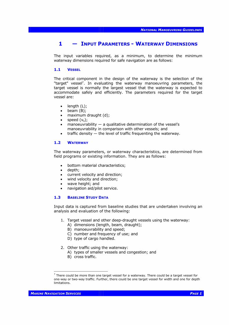
1 — INPUT PARAMETERS - WATERWAY DIMENSIONS
The input variables required, as a minimum, to determine the minimum waterway dimensions required for safe navigation are as follows: 1.1 VESSEL The critical component in the design of the waterway is the selection of the "target" vessel1. In evaluating the waterway manoeuvring parameters, the target vessel is normally the largest vessel that the waterway is expected to accommodate safely and efficiently. The parameters required for the target vessel are:
• length (L); • beam (B); • maximum draught (d); • speed (vs); • manoeuvrability — a qualitative determination of the vessel’s
manoeuvrability in comparison with other vessels; and • traffic density — the level of traffic frequenting the waterway.
1.2 WATERWAY The waterway parameters, or waterway characteristics, are determined from field programs or existing information. They are as follows:
• bottom material characteristics; • depth; • current velocity and direction; • wind velocity and direction; • wave height; and • navigation aid/pilot service.
1.3 BASELINE STUDY DATA Input data is captured from baseline studies that are undertaken involving an analysis and evaluation of the following:
1. Target vessel and other deep-draught vessels using the waterway: A) dimensions (length, beam, draught); B) manoeuvrability and speed; C) number and frequency of use; and D) type of cargo handled.
2. Other traffic using the waterway:
A) types of smaller vessels and congestion; and B) cross traffic.
1 There could be more than one target vessel for a waterway. There could be a target vessel for one-way or two-way traffic. Further, there could be one target vessel for width and one for depth limitations.

NATIONAL MANOEUVRING GUIDELINES
PAGE 2 MARINE NAVIGATION SERVICES
3. Weather:
A) wind (velocity, direction and duration); B) waves (heights, period, direction and duration); C) visibility (rain, smog, fog and snow, including duration and frequency
of impairment); D) ice (frequency, duration and thickness); and E) abnormal water levels (high or low).
4. Characteristics of a waterway:
A) currents, tidal and/or river (velocity, direction, and duration); B) sediment sizes and area distribution, movement, and serious scour
and shoal areas; C) type of bed and bank (soft or hard); D) alignment and configuration; E) freshwater inflow; F) tides; G) salinity; H) dredged material disposal areas; I) temperature; J) water quality; K) biological population (type, density, distribution and migration); L) obstructions (such as sunken vessels and abandoned structures); M) existing bridge and powerline crossings (location, type and
clearances); N) waterway constrictions; and O) submerged cables and pipelines.
The input parameters are used to develop the requirements and design considerations for channel width and depth, as demonstrated in the flow chart shown in Figure 1. Figure 2 and Figure 3 provide more detail on the width and depth parameters. 1.4 WATER LEVEL The depth of the waterway should be adequate to accommodate the deepest-draught vessel expected to use the waterway. However, this is not the case 100 percent of the time; it may be possible to schedule passage of the deepest-draught vessel during high water levels (i.e., high tide). Selection of the design draught should be based on an economic analysis of the cost of vessel delays, operation and light loading compared with construction and maintenance cost (Ref.: 1).

NATIONAL MANOEUVRING GUIDELINES
MARINE NAVIGATION SERVICES PAGE 3
Figure 1: Relevant Parameters for Waterway Design Procedures — Overview
Manoeuvring Lane
Vessel Clearance
Bank Suction
Wind Effect
Current Effect
Channel with Bends
Navigational Aids/Pilot
WIDTH
Draught
Trim
Squat
Exposure Allowance
Fresh Water Adjustment
Manoeuvrability Allowance
Overdepth Allowance
Depth Transition
Tidal Allowance
DEPTH
RELEVANT PARAMETERS

NATIONAL MANOEUVRING GUIDELINES
PAGE 4 MARINE NAVIGATION SERVICES
Figure 2: Relevant Parameters for Waterway Design Procedures — Width
Manoeuvring Lane
Vessel Clearance
Bank Suction
Wind Effect
Current Effect
Channel with Bends
Navigational Aids/Pilot
WIDTH
Vessel type and sizeControllability
Vessel sizeOperational Experience
Ratio of channel width/vessel beamRatio of channel depth/vessel draught
Vessel size, loaded or in ballastWind direction, wind speed/vessel speedVessel draught/channel depth
Vessel size, loaded or in ballastCurrent direction, current speed/vessel speed
Vessel size, speed, turning angle, controllabilityRadius of curvature, sight distanceCurve transition and curve alignments
DEPTH
WIDTH PARAMETERS
NATIONAL MANOEUVRING GUIDELINES
MARINE NAVIGATION SERVICES PAGE 5
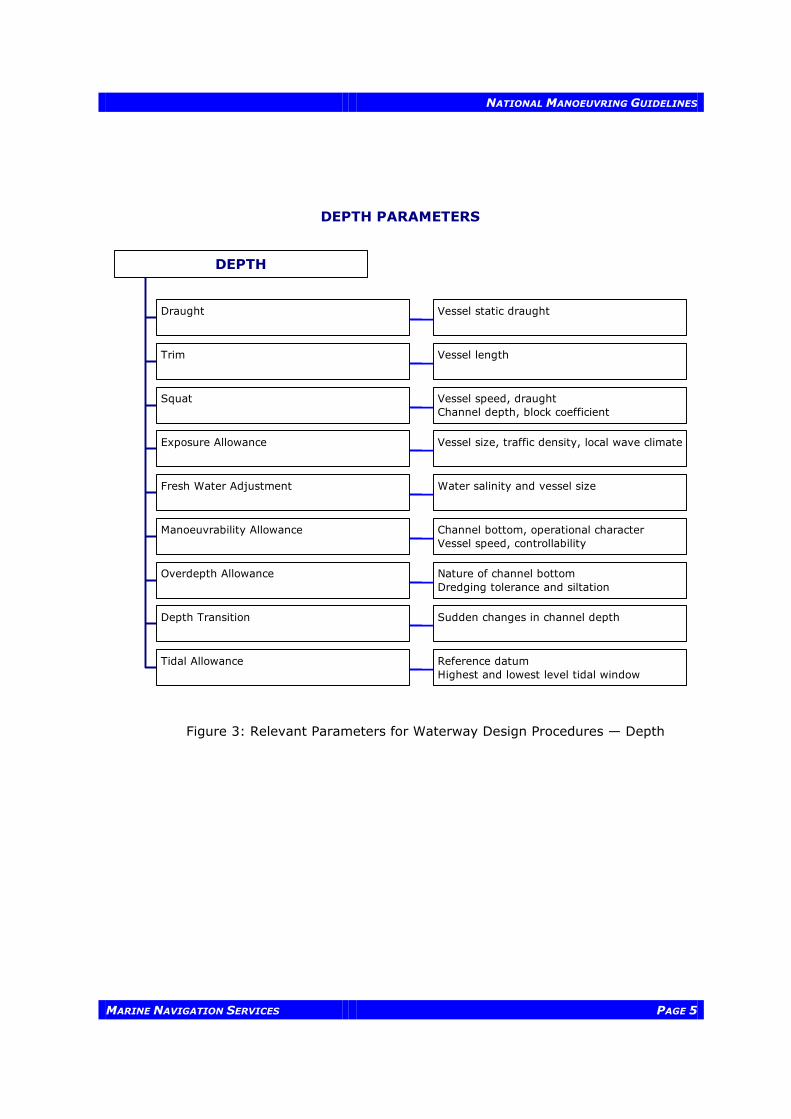
Figure 3: Relevant Parameters for Waterway Design Procedures — Depth
Draught
Trim
Squat
Exposure Allowance
Fresh Water Adjustment
Manoeuvrability Allowance
Overdepth Allowance
Depth Transition
Tidal Allowance
DEPTH
Vessel static draught
Vessel length
Vessel speed, draughtChannel depth, block coefficient
Vessel size, traffic density, local wave climate
Water salinity and vessel size
Channel bottom, operational characterVessel speed, controllability
Nature of channel bottomDredging tolerance and siltation
Sudden changes in channel depth
Reference datumHighest and lowest level tidal window
DEPTH
DEPTH PARAMETERS

NATIONAL MANOEUVRING GUIDELINES
PAGE 6 MARINE NAVIGATION SERVICES
2 — WIDTH
This section is divided into two parts called Version 1 (pages 6 to 11) and Version 2 (pages 12 to 17). Version 1 describes the width calculation using the parameters as described in the 1995 report. Version 2 is a refinement of the calculations of Version 1 by expanding on some parameters and by adding others to improve on the width calculation. Accordingly, two different softwares, called Version 1 and Version 2, are provided to allow users to select the option that best fits their needs. 2.1 VERSION 1 This section describes the procedure for determining the channel width required in straight sections using the critical parameters. (The calculation for the channel bends is provided in Section 5 on page 25) The basis for the variables included in the equations is the waterway target vessel. The total channel width refers to the horizontal distance measured from the toe-to-toe side slopes at the design depth. Total width is expressed as:
Total Width = Design Width + Allowances Design Width refers to the summation of width requirements for:
1. ship manoeuvring; 2. hydrodynamic interactions between meeting and passing vessels in
two-way traffic; 3. counteracting cross-winds and cross-current; 4. counteracting bank suction; and 5. navigational aids.
Allowances refer to additional width increases to compensate for bank slumping and erosion, sediment transport and deposition, as well as the type of bank material (See Figure 4) (Ref.: 1). 2.1.1 Manoeuvring Lane The manoeuvring lane is the width required to allow for the oscillating track produced by the combination of sway and yaw of the vessel. The oscillation is partly due to forces acting on a moving ship, such as directional instability and response to rudder action, and the human response to course deviations. Manoeuvring lane widths should be calculated for the largest of the most frequently expected vessel type, and the resulting largest lane should be adopted as the required manoeuvring lane width. In some cases, depending on the traffic structure, the channel width may accommodate two-way traffic for a certain range of vessel sizes and one-way traffic for a larger range of traffic. Also Traffic Services and adequate traffic scheduling can help in determining the optimal channel width.

NATIONAL MANOEUVRING GUIDELINES
MARINE NAVIGATION SERVICES PAGE 7
Figure 4: Interior Channel Width Elements
CHANNEL WIDTH, ONE-WAY TRAFFIC
ALL
OW
ANC
E
BAN
K C
LEAR
ANC
E
BAN
K C
LEAR
ANC
E
ALL
OW
ANC
E
MAN
OEU
VRIN
G L
ANE
CHANNEL WIDTH, TWO-WAY TRAFFIC
AL
LOW
ANC
E
B
ANK
CLE
ARAN
CE
BAN
K C
LEAR
ANC
E
ALL
OW
ANC
E
M
ANO
EUVR
ING
LAN
E
M
ANO
EUVR
ING
LAN
E
SH
IP C
LEAR
ANC
E
Figure 2: INTERIOR CHANNEL WIDTH ELEMENTS

NATIONAL MANOEUVRING GUIDELINES
PAGE 8 MARINE NAVIGATION SERVICES
In the design of the manoeuvrability lane, an assessment has to be made of the vessel manoeuvring characteristics. Table 1 shows the assumptions used to arrive at an assessment of the vessel’s manoeuvrability and the resulting lane requirements. Depending on the type of target vessel, a "manoeuvrability coefficient" is multiplied by the target vessel’s beam (B) to determine the manoeuvring lane width.
Table 1: Manoeuvrability Coefficients for Various Vessel Types2
Vessel Manoeuvrability Manoeuvrability Coefficient
Manoeuvring Lane Width
Naval fighting vessels, Victory ship class freighters
Excellent
1.6
1.6 B
Tankers, new ore ships, Liberty class freighters
Good
1.8
1.8 B
Old ore ships, damaged vessels
Poor 2.0 2.0 B
where B = “target” vessel beam (Ref: 1, 5, 8, 9, 12)
2.1.2 Hydrodynamic Interaction Lane (Ship Clearance) As two vessels pass, there are strong interaction forces between them giving rise to path deviations and heading changes. Even though the interaction forces are quite large, the magnitudes of the path deviations and heading changes during the actual passing of the vessels are small. The real danger lies after the vessels have passed, when the dynamic disturbances imparted to the vessels during passing can combine with bank effects and lead to oscillating diverging motions if not properly controlled. The minimum hydrodynamic interaction width desired is 30 metres (100 feet). The recommended approach is: Vessel Clearance = 1 B, if B > 30 m OR Vessel Clearance = 30 m, if B < 30 m (Ref.: 1, 5, 7, 9, 12) 2.1.3 Wind/Current Effects Wind forces on a vessel produce two effects: a sideways drift and a turning moment. The former is overcome by steering a course to counteract it, and the latter is overcome by applying a certain amount of helm. Counteracting the drift will induce vessel yaw; this requires a widening of the channel. The degree to which wind affects a vessel depends on the relative direction of the wind, the ratio of wind speed to vessel speed, the depth to draught ratio and whether the vessel is loaded or in ballast.
2 For the majority of the preliminary designs for which this guideline is intended, the vessel can be assumed to have “Good” manoeuvrability

NATIONAL MANOEUVRING GUIDELINES
MARINE NAVIGATION SERVICES PAGE 9
Winds from the bow are generally not a concern for wind speeds less than 10 times the vessel speed. However, winds become a greater concern as the wind shifts abeam. The maximum effect occurs perpendicular to the ship’s beam. The yaw angle caused by wind is most severe for a vessel in ballast. Therefore, it is the ballast condition that is used to determine the additional channel width required for wind effects. The influence of cross current on a vessel principally follows the same requirements as those for crosswinds. If the wind and current cause a yaw angle of > 50, the recommended requirements are listed in Table 2.
Table 2: Wind/Current Width Requirement
Manoeuvrability3 Wind/Current Width Requirement-Severity
Low Medium High
Excellent 0.6 B 0.8 B 1.0 B
Good 0.7 B 0.9 B 1.1 B
Poor 0.8 B 1.0 B 1.2 B
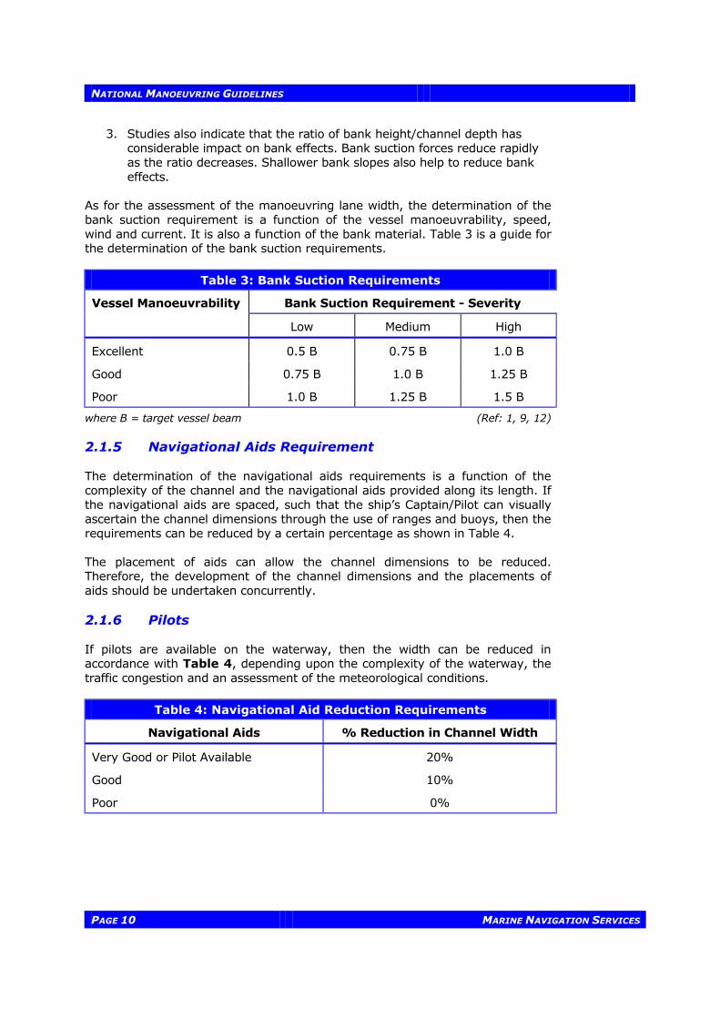
where B = "target" vessel beam (Ref: 5, 8) 2.1.4 Bank Suction Requirement (Bank Clearance) When a ship moves through water, the water is displaced at the bow and transported back around the hull to fill the void behind the stern. Flow-produced lateral pressures are balanced when the ship is proceeding in an open channel or on the centre-line of a symmetrical channel. However, when the ship is moving parallel to, but off the channel centre-line, the forces are asymmetrical resulting in a yawing moment. The yawing moment is produced by the building of a wave system between the bow and the near channel bank. Behind this bow wave, the elevation of the water between the vessel and the near bank is less than between the vessel and the centre-line of the channel with a force being produced tending to move the stern toward the near bank. This effect is called bank suction and increases directly with the distance the sailing line is from the centre-line of the channel. The magnitude of the bank suction effect is influenced by a number of factors:
1. The distance of the vessel from the bank—theory and tests indicate that the magnitude of the lateral force varies approximately as a function of the cube of the distance.
2. The magnitude of the forces increases with decreasing depth/draught
ratios and increasing speed.
3 See Table 1 for indication of the manoeuvrability characteristics of vessels
NATIONAL MANOEUVRING GUIDELINES
PAGE 10 MARINE NAVIGATION SERVICES
3. Studies also indicate that the ratio of bank height/channel depth has considerable impact on bank effects. Bank suction forces reduce rapidly as the ratio decreases. Shallower bank slopes also help to reduce bank effects.
As for the assessment of the manoeuvring lane width, the determination of the bank suction requirement is a function of the vessel manoeuvrability, speed, wind and current. It is also a function of the bank material. Table 3 is a guide for the determination of the bank suction requirements.
Table 3: Bank Suction Requirements
Vessel Manoeuvrability Bank Suction Requirement - Severity
Low Medium High
Excellent 0.5 B 0.75 B 1.0 B
Good 0.75 B 1.0 B 1.25 B
Poor 1.0 B 1.25 B 1.5 B
where B = target vessel beam (Ref: 1, 9, 12) 2.1.5 Navigational Aids Requirement The determination of the navigational aids requirements is a function of the complexity of the channel and the navigational aids provided along its length. If the navigational aids are spaced, such that the ship’s Captain/Pilot can visually ascertain the channel dimensions through the use of ranges and buoys, then the requirements can be reduced by a certain percentage as shown in Table 4. The placement of aids can allow the channel dimensions to be reduced. Therefore, the development of the channel dimensions and the placements of aids should be undertaken concurrently. 2.1.6 Pilots If pilots are available on the waterway, then the width can be reduced in accordance with Table 4, depending upon the complexity of the waterway, the traffic congestion and an assessment of the meteorological conditions.
Table 4: Navigational Aid Reduction Requirements
Navigational Aids % Reduction in Channel Width
Very Good or Pilot Available 20%
Good 10%
Poor 0%

NATIONAL MANOEUVRING GUIDELINES
MARINE NAVIGATION SERVICES PAGE 11
2.1.7 Other Allowances The previous topics cover the major concerns with the design of the channel width. There are, however, additional items that should be considered in the assessment of the required width of the channel. Vessel Cargo In this day of environmental consciousness, the designer should consider the vessel cargo as part of the evaluation of waterway safety and the associated risks. For instance, if the majority of the traffic is crude versus bulk grain, the designer should provide a channel width that makes the chance of grounding or interaction a rare event with an annual probability of occurrence of 1 x 10⁻⁵. The present approach is to address this issue through the use of navigational aids. Night Time Transit and Fog Effect The effect of vessel visibility in the channel is another parameter that needs to be qualitatively evaluated by the designer. The designer should take into consideration the number of fog free days when considering channel width requirements. With the development of global positioning systems and differential global positioning systems to enhance the reliance of vessel navigation, this parameter may be of lesser importance.
NATIONAL MANOEUVRING GUIDELINES
PAGE 12 MARINE NAVIGATION SERVICES
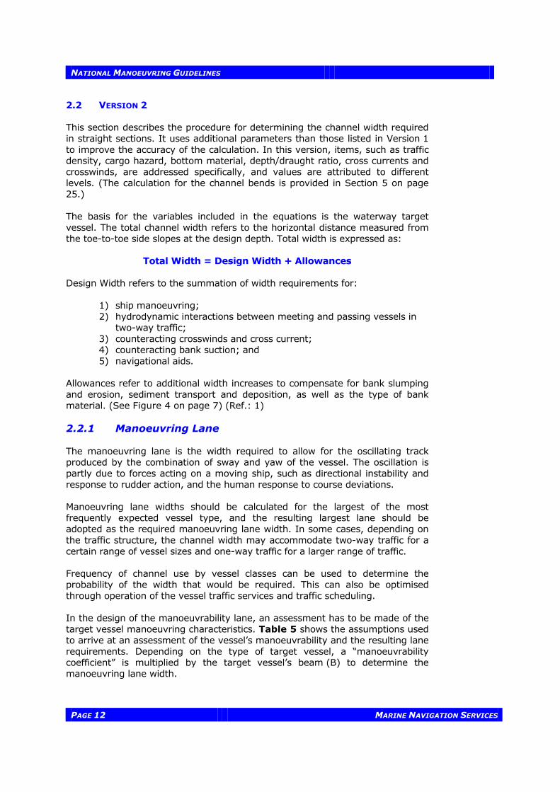
2.2 VERSION 2 This section describes the procedure for determining the channel width required in straight sections. It uses additional parameters than those listed in Version 1 to improve the accuracy of the calculation. In this version, items, such as traffic density, cargo hazard, bottom material, depth/draught ratio, cross currents and crosswinds, are addressed specifically, and values are attributed to different levels. (The calculation for the channel bends is provided in Section 5 on page 25.) The basis for the variables included in the equations is the waterway target vessel. The total channel width refers to the horizontal distance measured from the toe-to-toe side slopes at the design depth. Total width is expressed as:
Total Width = Design Width + Allowances Design Width refers to the summation of width requirements for:
1) ship manoeuvring; 2) hydrodynamic interactions between meeting and passing vessels in
two-way traffic; 3) counteracting crosswinds and cross current; 4) counteracting bank suction; and 5) navigational aids.
Allowances refer to additional width increases to compensate for bank slumping and erosion, sediment transport and deposition, as well as the type of bank material. (See Figure 4 on page 7) (Ref.: 1) 2.2.1 Manoeuvring Lane The manoeuvring lane is the width required to allow for the oscillating track produced by the combination of sway and yaw of the vessel. The oscillation is partly due to forces acting on a moving ship, such as directional instability and response to rudder action, and the human response to course deviations. Manoeuvring lane widths should be calculated for the largest of the most frequently expected vessel type, and the resulting largest lane should be adopted as the required manoeuvring lane width. In some cases, depending on the traffic structure, the channel width may accommodate two-way traffic for a certain range of vessel sizes and one-way traffic for a larger range of traffic. Frequency of channel use by vessel classes can be used to determine the probability of the width that would be required. This can also be optimised through operation of the vessel traffic services and traffic scheduling. In the design of the manoeuvrability lane, an assessment has to be made of the target vessel manoeuvring characteristics. Table 5 shows the assumptions used to arrive at an assessment of the vessel’s manoeuvrability and the resulting lane requirements. Depending on the type of target vessel, a “manoeuvrability coefficient” is multiplied by the target vessel’s beam (B) to determine the manoeuvring lane width.

NATIONAL MANOEUVRING GUIDELINES
MARINE NAVIGATION SERVICES PAGE 13
Table 5: Manoeuvrability Coefficients for Various Vessel Types4
Vessel Manoeuvrability Manoeuvrability Coefficient
Manoeuvring Lane Width
Naval fighting vessels, Victory ship class freighters
Excellent
1.3
1.3 B
Tankers, new ore ships, Liberty class freighters
Good
1.5
1.5 B
Old ore ships, damaged vessels
Poor 1.8 1.8 B
where B = target vessel beam (Ref: 1, 5, 8, 9, 12, 13)
2.2.2 Hydrodynamic Interaction Lane (Ship Clearance) As two vessels pass, there are strong interaction forces between them, giving rise to path deviations and heading changes. Even though the interaction forces are quite large, the magnitudes of the path deviations and heading changes during the actual passing of the vessels are small. The real danger lies after the vessels have passed when the dynamic disturbances imparted to the vessels during passing can combine with bank effects and lead to oscillating diverging motions if not properly controlled. The minimum hydrodynamic interaction width desired is 30 metres (100 feet). The recommended approach is: Vessel Clearance = 1 B, if B > 30 m OR Vessel Clearance = 30 m, if B < 30 m (Ref.: 1, 5, 7, 9, 12) Encounter traffic density should also be considered in two-way traffic channels. Additional width is required for channels with heavy traffic density. The requirements for traffic density are shown below in Table 6.
Table 6: Additional Width Requirement for Traffic Density
Traffic Density* Width Requirement
Light (0 - 1.0 vessel/hour) 0.0 B
Moderate ( 1.0 - 3.0 vessel/hour ) 0.2 B
Heavy ( > 3.0 vessel /hour) 0.4 B
* The vessels considered exclude small craft such as pleasure and fishing vessels. The values per hour are not necessarily daily means; peak periods should be considered when analysing traffic patterns.
4 For the majority of the preliminary designs for which this guideline is intended, the vessel can be assumed to have “Good” manoeuvrability

NATIONAL MANOEUVRING GUIDELINES
PAGE 14 MARINE NAVIGATION SERVICES
2.2.3 Wind and Current Effects Wind forces on a vessel produce two effects: a sideways drift and a turning moment. The former is overcome by steering a course to counteract it, and the latter is overcome by applying a certain amount of helm. Counteracting the drift will induce vessel yaw; this requires a widening of the channel. The degree to which wind affects a vessel depends on the relative direction of the wind, the ratio of wind speed to vessel speed, the depth to draught ratio and whether the vessel is loaded or in ballast. Winds from the bow are generally not a concern for wind speeds less than 10 times the vessel speed. However, winds become a greater concern as the wind shifts abeam. The maximum effect occurs perpendicular to the ship’s beam. The yaw angle caused by wind is most severe for a vessel in ballast. Therefore, it is the ballast condition that is used to determine the additional channel width required for wind effects. The width requirement for wind effects is shown in Table 7 below.
Table 7: Additional Width Requirement for Prevailing Crosswinds
Wind Severity Width Requirement for vessel Manoeuvrability
Excellent Good Poor
Low (< 15 knots) 0.0 B 0.0 B 0.0 B
Moderate (15-33 knots) 0.3 B 0.4 B 0.5 B
Severe (> 33 knots) 0.6 B 0.8 B 1.0 B
where B = "target" vessel beam (Ref: 5, 8, 13) The influence of cross current on a vessel principally follows similar requirements as those for crosswinds, as shown in Table 8 below.
Table 8: Additional Width Requirement for Prevailing Cross Current
Current Severity Width Requirement for vessel Manoeuvrability
Excellent Good Poor
Negligible ( < 0.2 knots ) 0.0 B 0.0 B 0.0 B
Low ( 0.2 - 0.5 knots ) 0.1 B 0.2 B 0.3 B
Moderate ( 0.5 - 1.5 knots ) 0.5 B 0.7 B 1.0 B
Severe ( > 1.5 knots ) 0.7 B 1.0 B 1.3 B
where B = "target" vessel beam (Ref: 5, 8, 13)

NATIONAL MANOEUVRING GUIDELINES
MARINE NAVIGATION SERVICES PAGE 15
2.2.4 Bank Suction Requirement (Bank Clearance) When a ship moves through water, the water is displaced at the bow and transported back around the hull to fill the void behind the stern. Flow-produced lateral pressures are balanced when the ship is proceeding in an open channel or on the centre-line of a symmetrical channel. However, when the ship is moving parallel to, but off the channel centre-line, the forces are asymmetrical resulting in a yawing moment. The yawing moment is produced by the building of a wave system between the bow and the near channel bank. Behind this bow wave, the elevation of the water between the vessel and the near bank is less than between the vessel and the centre-line of the channel with a force being produced tending to move the stern toward the near bank. This effect is called bank suction and increases directly with the distance the sailing line is from the centre-line of the channel. The magnitude of the bank suction effect is influenced by a number of factors:
1. The distance of the vessel from the bank—theory and tests indicate that the magnitude of the lateral force varies approximately as a function of the cube of the distance.
2. The magnitude of the forces increases with decreasing depth/draught
ratios and increasing speed. 3. Studies also indicate that the ratio of bank height/channel depth has
considerable impact on bank effects. Bank suction forces reduce rapidly as the ratio decreases. Shallower bank slopes also help to reduce bank effects.
As for the assessment of the manoeuvring lane width, the determination of the bank suction requirement is a function of the vessel manoeuvrability, speed, wind and current. It is also a function of the bank material. Table 3 is a guide for the determination of the bank suction requirements.
Table 9: Additional Width Requirement for Bank Suction
Vessel Manoeuvrability5 Width Requirement - Severity
Low Medium High
Excellent 0.5 B 0.75 B 1.0 B
Good 0.75 B 1.0 B 1.25 B
Poor 1.0 B 1.25 B 1.5 B
where B = "target" vessel beam (Ref: 1, 9, 12) 2.2.5 Navigational Aids Requirement The determination of the navigational aids requirements is a function of the complexity of the channel and the navigational aids provided along its length. If, for example, the navigational aids are spaced such that the ship’s Captain/Pilot
5 See Table 1 for indication of the manoeuvrability characteristics of vessels.

NATIONAL MANOEUVRING GUIDELINES
PAGE 16 MARINE NAVIGATION SERVICES
can visually ascertain the channel dimensions through the use of ranges and buoys, then no additional width is required. Therefore, the development of the channel dimensions and the placements of aids should be undertaken concurrently. Table 10 shows the additional width requirements according to the status of navigational aids. This table also includes the availability of pilots which will have a definite influence on the additional width requirement.
Table 10: Additional Width Requirement for Navigational Aids
Navigational Aids Width Requirement
Excellent 0.0 B
Good 0.1 B
Moderate with infrequent poor visibility 0.2 B
Moderate with frequent poor visibility 0.5 B
2.2.6 Other Allowances The previous topics cover the major concerns with the design of the channel width. There are, however, additional items that should be considered in the assessment of the required width of the channel. Vessel Cargo In this day of environmental consciousness, the designer should consider the vessel cargo as part of the evaluation of waterway safety and the associated risks. For instance, if the majority of the traffic is crude versus bulk grain, the designer should provide a channel width that makes the chance of grounding or interaction a rare event with an annual probability of occurrence of 1 x 10⁻⁵. The present approach is to address this issue through the use of navigational aids. Table 11 shows the requirement for type of cargo for a one-lane channel.
Table 11: Additional Width Requirement for Cargo Hazard
Cargo hazard level Width Requirement
Low 0.0 B
Medium 0.5 B
High 1.0 B
Depth of the Waterway Sufficient channel depth is required to maintain vessel manoeuvrability. A simple way to account for this is to set a minimum value for water depth/draught ratio. In many parts of the world, a value of 1.10 has become acceptable, although a value of 1.15 is also often used. The closer the ratio is to unity, the more directionally stable (i.e., difficult to alter course) is the ship and, consequently, the more sluggish its response. It is usual practice to allow for this by increasing channel width. The width requirement for the depth/draught ratio is shown in Table 12.
NATIONAL MANOEUVRING GUIDELINES
MARINE NAVIGATION SERVICES PAGE 17
Table 12: Additional Width Requirement for Depth/Draught Ratio
Depth/Draught Ratio (D/d) Width Requirement
D/d > 1.50 0.0 B
1.15 ≤ D/d ≤ 1.50 0.2 B
D/d <1.15 0.4 B
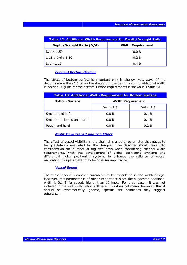
Channel Bottom Surface The effect of bottom surface is important only in shallow waterways. If the depth is more than 1.5 times the draught of the design ship, no additional width is needed. A guide for the bottom surface requirements is shown in Table 13.
Table 13: Additional Width Requirement for Bottom Surface
Bottom Surface Width Requirement
D/d > 1.5 D/d < 1.5
Smooth and soft 0.0 B 0.1 B
Smooth or sloping and hard 0.0 B 0.1 B
Rough and hard 0.0 B 0.2 B
Night Time Transit and Fog Effect The effect of vessel visibility in the channel is another parameter that needs to be qualitatively evaluated by the designer. The designer should take into consideration the number of fog free days when considering channel width requirements. With the development of global positioning systems and differential global positioning systems to enhance the reliance of vessel navigation, this parameter may be of lesser importance. Vessel Speed The vessel speed is another parameter to be considered in the width design. However, this parameter is of minor importance since the suggested additional width is 0.1 B for speeds higher than 12 knots. For that reason, it was not included in the width calculation software. This does not mean, however, that it should be systematically ignored; specific site conditions may suggest otherwise.

NATIONAL MANOEUVRING GUIDELINES
PAGE 18 MARINE NAVIGATION SERVICES
3 — DEPTH
Minimum Waterway Depth for safe navigation is calculated from the sum of the draught of the design vessel as well as a number of allowances and requirements as seen in the following formula: Actual Waterway Depth6 = Target Vessel Static Draught + Trim + Squat +
Exposure Allowance + Fresh Water Adjustment + Bottom Material Allowance + Overdepth Allowance + Depth Transition - Tidal Allowance, (see Figure 5: Components of Waterway Depth)
Project (Advertised) Waterway Depth = Waterway Depth - Overdepth Allowance In addition to the factors affecting Waterway Depth included in this section, others that should also be taken into account include:
• the effect of currents in the waterway; • the effect of water levels in the waterway and adjoining water bodies, by
such changes as river flow and wind set up; • environmental effects; and • limiting depths elsewhere in the waterway.
In the determination of the design draught, it should be realised that the depth does not necessarily have to be available 100 percent of the time. This may require the deepest-draught vessel to schedule passage during high water levels. Selection of the design depth should be based on an economic analysis of the cost of vessel delays, operation and light load, compared with construction and maintenance costs. 3.1 TARGET VESSEL STATIC DRAUGHT The draught of the target vessel that will be using the waterway is based on the anticipated ship traffic for the proposed waterway. These dimensions are selected by an economic evaluation of the ship traffic for the waterway. 3.2 TRIM Trim is generally defined as the longitudinal inclination of a ship, or the difference in draught from the bow to the stern. It is controlled by loading. In general, at low speed, a ship underway will squat by the bow. The practice is to counteract this squat by trimming the ship by the stern when loading. The rule of thumb is to provide an allowance of 0.31 m to account for trim in waterway design (Ref.: 5,9). The normal approach for a vessel is to assume a trim rate of 3"/100 ft of length or 0.25 m/100 m (Ref.: 3,5,9).
6 In the application of the formula, a decision should be made as to whether the trim and squat values should be added. In the standard case only, the squat value is used to determine the “actual channel depth.”

NATIONAL MANOEUVRING GUIDELINES
MARINE NAVIGATION SERVICES PAGE 19
(DYNAMIC DRAUGHT)
MINIMUM WATER LEVELFOR DESIGN DRAUGHT
SHIP
TIDAL EFFECT
STATICDRAUGHT
ALLOWANCE - SQUATFOR VERTICAL -TRIMMOVEMENT - EXPOSURE
FRESH WATER ADJUSTMENT
MATERIAL ALLOWANCE
OVER DEPTHALLOWANCE
-SILTATION ALLOWANCE,
-TOLERANCES FOR DREDGING & SOUNDING
LOWEST ELEVATIONOF SHIP BOTTOM
CHART DATUM
AC
TUA
L D
EP
TH
AD
VE
RTI
SE
D D
EP
TH
������������������������������������������
������������������������������������
������������������������������������������
������������������������������������������������������
���������������������������������������������
���������������������������������������������������
���������������������������������������������
���������������������������������������������������
���������������������������������������������
���������������������������������������������������
���������������������������������������������
(NET UNDERKEEL CLEARANCE)
Figure 5: Components of Waterway Depth

NATIONAL MANOEUVRING GUIDELINES
PAGE 20 MARINE NAVIGATION SERVICES
3.3 TIDAL ALLOWANCE The selection of an allowance for tidal effect should be derived from examination of a statistically significant sample of tidal records during the navigation season to determine to what extent tidal height above the chart datum should be included as part of the normally available water depth. The allowance selected should give the required level of waterway availability based on tidal scheduling determined through optimization analysis. 3.4 SQUAT Squat refers to the increase of a ship’s draught as a result of its motion through water. It is a hydraulic phenomenon whereby the water displaced creates an increase in current velocity past the moving hull causing a reduction in pressure resulting in a localised reduction of the water level and, consequently, in a settling of the vessel deeper in the water. For various reasons—having to do with hull design, trim and other physical and operational factors—squat may be different at the fore and aft. Recently, a new equation was developed on the basis of extensive research by Waterways Development to specifically target commercial waterways with vessel traffic and conditions representative of most major Canadian waterways. This equation takes into account the vessel beam in relation to the channel width, contrary to earlier equations that supposed infinite width. This new parameter is of importance since most Canadian waterways have limited width. The equation, known as Eryuzlu Equation # 3 (Ref.: 4, this reference is attached to this manual as Appendix 4), is therefore recommended as the one providing the most reliable results in waterways of limited dimensions. The equation is written as follows:
[ ]Z(d/D )=a[v / gd] D / d F2s
b cw
where: Z = squat; d = vessel draught; D = channel depth; vs = vessel speed; g = gravity acceleration; W = channel width; B = vessel beam; and Fw = channel width factor.
With Fw = 1, where W > 9.61 B;
a, b, c are common coefficients: a = 0.298, b = 2.289, c = -2.972
wF = 3.1W / B
, where W < 9.61 B; and
The equation is non-dimensional and therefore, can be used universally with any system of measurement units.

NATIONAL MANOEUVRING GUIDELINES
MARINE NAVIGATION SERVICES PAGE 21
Applications7
The formula applies for:
1. vessels ranging from 19,000 DWT to 227,000 DWT, representing general cargo or crude carriers (block coefficient over 0.80);
2. a channel that is shallow and relatively straight; 3. the channel width may range from unrestricted to four times the vessel
beam; 4. speeds ranging from about 2 knots to about 14 knots; 5. maximum trim of about 10 % of draft; 6. the predominant squat is fore squat; and 7. vessel loaded draft equal to or greater than 80% of the registered draft.
Formulae, by definition, tend to generalize the real situation. Therefore, good judgement, experience and common sense are required in the use of this and any formula. 3.5 DEPTH ALLOWANCE FOR EXPOSURE The selection of the exposure allowance should take into account the movements of heaving, pitching and rolling caused by local conditions, and should be based on available information on the local wave climate and vessel traffic considerations. The allowance should be selected so as to minimize arrival and departure delays accounting for economic considerations. If a substantial allowance is required for a minimal reduction in delays or the delay problems are minimal with low traffic, the allowance can be omitted. However, for other cases, the supplementary depth can be based on the information provided in Table 14. (Larger values may be required in waterways on the East and West Coasts).
Table 14: Additional Depth Allowance for Exposure8
Exposure Depth Allowance
Unexposed 0 m
Medium Exposure (Minor Vessel Heaving) .15 m
Fully Exposed .30 m
3.6 FRESH WATER ADJUSTMENT Salinity increases the density of water, in turn reducing the draught of the vessel in the waterway. Design of the waterway depth should account for fluctuations in the salinity that may occur in an estuary exposed to tidal influences and river discharges. An adjustment for fresh water should account for the decreased buoyancy of the vessel.
7 The planner should consider these when undertaking the determination of the squat. 8 These values represent typical allowances for the Great Lakes waterways.

NATIONAL MANOEUVRING GUIDELINES
PAGE 22 MARINE NAVIGATION SERVICES
A rule of thumb to determine the additional loading allowance for vessels in fresh water is to set it at 2-3% of the salt water draught (Ref.: 1,5,9). 3.7 BOTTOM MATERIAL ALLOWANCE This allowance, also known as the Net Underkeel Clearance, is by definition the minimum safety margin between the keel of the vessel and the project (advertised) waterway depth. This allowance is provided in addition to the allowances for squat, trim, freshwater and the influence of the design wind and wave conditions in order to ensure a safety margin against striking the bottom. The value is a function of the nature of the bottom, the handling characteristics of the vessel and the operational character of the waterway. Table 15 summarises the values that may be used as a function of the Bottom Material.
Table 15: Additional Depth Allowance for Bottom Material
Bottom Material Depth Allowance
Soft 0.25 m
Medium (Sand) 0.60 m
Hard Bottom (Rock) 0.90 m
(Ref: 2,7,8,9) 3.8 MANOEUVRABILITY MARGIN The Manoeuvrability Margin is made up of the allowance for bottom material (or the Net Underkeel Clearance) and the exposure allowance. This margin is a measure of the minimum required to allow the vessel to manoeuvre adequately in the waterway. A minimum margin of 1.0 m is generally used for the operation of large vessels. Therefore, the sum of the Bottom Material Allowance and Exposure Allowance should be at least 1.0 m to accommodate the Manoeuvrability Margin for vessels of 250,000 DWT and greater (Ref.: 10). 3.9 OVERDEPTH ALLOWANCE Overdepth Allowance refers to an allowance to account for waterway siltation between dredging and tolerance of sounding and dredging. The dredging tolerance varies with the type of dredging plant employed and the bottom conditions. The average acceptable tolerance is 0.3 m. If the bottom material is soft and can be displaced by a ship, no tolerance allowance is necessary (Ref.: 1). An allowance for siltation is usually based on the anticipated accumulation patterns of the silt. The allowance is designed to accommodate the siltation between dredging operations.

NATIONAL MANOEUVRING GUIDELINES
MARINE NAVIGATION SERVICES PAGE 23
3.10 DEPTH TRANSITION All reaches of the waterway must be examined and depths set according to the varying conditions encountered. This, and the natural bathymetry of the waterway, will lead to the provision of different depths in adjacent sections of the waterway. If the transition between adjacent reaches is large, the sudden change in Underkeel Clearance will have an effect on the current velocities and hydrostatic pressure on the hull. The result will be a change in the ship’s performance, manoeuvrability and draught. Vessel squat in a transition area is presently being evaluated by Waterways Development. The preliminary analysis shows that the squat would increase by 15% to 20% when the transition is from deep water to shallow water.

NATIONAL MANOEUVRING GUIDELINES
PAGE 24 MARINE NAVIGATION SERVICES
4 — SIDE SLOPE
The selection of a suitable side slope is necessary to reduce waterway maintenance and for protection of vessels. In order to minimize hull damage, a maximum side slope of 1:1 is recommended to allow some movement of the vessel up the bank in the event of a collision. Table 16 provides a guide to the maximum slopes for stability. Slope stability analyses should be undertaken to ensure the factor of safety of the slope is greater than 1.25.
Table 16: Recommended Side Slopes
SOIL MATERIAL SIDE SLOPE Horizontal:Vertical
All Materials, minimum required side slopes 1:1
Preferred side slopes • Firm Rock 1:1 • Fissured rock, more or less disintegrated rock,
tough hardpan 1:1
• Cemented gravel, stiff clay soils, ordinary hardpan 1:1 • Firm, gravely, clay soil 1:1 • Average loam, gravely loam 3:2 • Firm clay 3:2 • Loose sandy loam 2:1 • Very sandy soil 3:1 • Sand and gravel, without or with little fines 3:1 - 4:1 • Sand and gravel with fines 4:1 - 5:1 • Muck and peat soil 4:1 • Mud and soft silt 6:1 - 8:1
NATIONAL MANOEUVRING GUIDELINES
MARINE NAVIGATION SERVICES PAGE 25
5 — BENDS
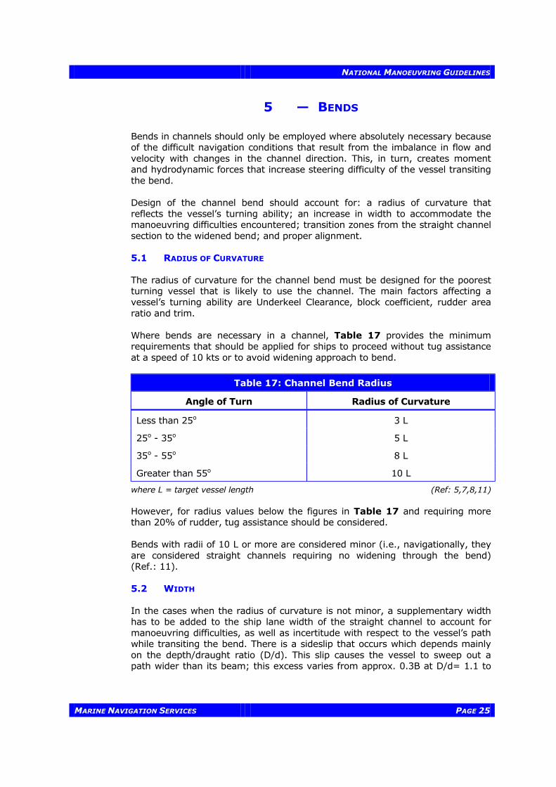
Bends in channels should only be employed where absolutely necessary because of the difficult navigation conditions that result from the imbalance in flow and velocity with changes in the channel direction. This, in turn, creates moment and hydrodynamic forces that increase steering difficulty of the vessel transiting the bend. Design of the channel bend should account for: a radius of curvature that reflects the vessel’s turning ability; an increase in width to accommodate the manoeuvring difficulties encountered; transition zones from the straight channel section to the widened bend; and proper alignment. 5.1 RADIUS OF CURVATURE The radius of curvature for the channel bend must be designed for the poorest turning vessel that is likely to use the channel. The main factors affecting a vessel’s turning ability are Underkeel Clearance, block coefficient, rudder area ratio and trim. Where bends are necessary in a channel, Table 17 provides the minimum requirements that should be applied for ships to proceed without tug assistance at a speed of 10 kts or to avoid widening approach to bend.
Table 17: Channel Bend Radius
Angle of Turn Radius of Curvature
Less than 25o 3 L
25o - 35o 5 L
35o - 55o 8 L
Greater than 55o 10 L
where L = target vessel length (Ref: 5,7,8,11)
However, for radius values below the figures in Table 17 and requiring more than 20% of rudder, tug assistance should be considered. Bends with radii of 10 L or more are considered minor (i.e., navigationally, they are considered straight channels requiring no widening through the bend) (Ref.: 11). 5.2 WIDTH In the cases when the radius of curvature is not minor, a supplementary width has to be added to the ship lane width of the straight channel to account for manoeuvring difficulties, as well as incertitude with respect to the vessel’s path while transiting the bend. There is a sideslip that occurs which depends mainly on the depth/draught ratio (D/d). This slip causes the vessel to sweep out a path wider than its beam; this excess varies from approx. 0.3B at D/d= 1.1 to

NATIONAL MANOEUVRING GUIDELINES
PAGE 26 MARINE NAVIGATION SERVICES
1.6B in deep water9. The magnitude of the width increase is also a function of the vessel turning angle, radius of curvature, sight distance, environmental conditions, as well as the length, beam, speed and manoeuvrability of the vessel. The following equation for determining the increase in channel width in bends was developed from the Dave Taylor Model Basin studies:
∆W = 0.9144 v L FR C S
s2 2
t c
φ
Where: ∆W = increase in the ship lane width, (m); φ = angle of turn, degrees; vs = speed of ship in channel relative to the bottom, (kts); L = ship length, (m); Rt = turning radius, (m); Cc = coefficient of vessel manoeuvrability (turning ability)
(poor = 1; good = 2; very good = 3); S = unobstructed sight distance from the bridge of the ship,
(metres); and F = 1.0 for one way traffic; 2.0 for two way traffic.
The minimum required sight distance, S, was determined by navigators during the Panama Canal studies to be 2446 m (1.52 statute miles) (Ref.: 5, 9). Due to the difficulty in predicting the hydrodynamic forces as a vessel transits a gradually widening bend—especially when currents are flowing—it is recommended that the width of the channel should remain constant throughout the bend. The increased channel width in a bend may be undertaken by one of three methods: (a) the cut-off method; (b) the parallel banks’ method; and (c) the non-parallel banks’ method (Ref.: 5). The cut-off method has been used for the St. Lawrence Seaway and has the advantage of requiring less dredging than the other methods. The Panama Canal studies, however, found that for certain applications the cut-off method produced undesirable current patterns (Ref.: 9). In those areas where the minimum requirements for radius cannot be met and the channel cannot be widened, tug assistance shall be required. 5.3 TRANSITIONS A transition zone from the straight section of the channel to the increased width of the bend is required to provide for the increasing asymmetric forces exerted on the ship as it enters the turn. The ends of zones having different widths should be joined by straight lines of length at least equal to the reach of the target vessel (Ref.: 11), but not less than a length/additional width ratio of 10:1 to provide a smoother change from the straight section to the widened cross section of the bend. The widening of the channel should occur on the straight portions of the channel and not on the bend itself. Figure 6 provides an explanation of the vessel reach calculations.
9 Approach Channels, A Guide for Designs; Final report of the joint Working Group PIANC and IAPH; Supplement to Bulletin no 95; June 1997; Page 19.

NATIONAL MANOEUVRING GUIDELINES
MARINE NAVIGATION SERVICES PAGE 27
Figure 7 summarises the criteria for dimensioning a parallel widened channel bend. Transitions - Design Example Find the transition length for a channel bend widened to an additional 20 m when,
Vessel speed, vs = 4.12 m/s (8 kts) Turning lag, T = 30 seconds Reach = T x vs
= 30 x 4.12 = 123.5 m
Compare to the ratio of transition length/additional width (Lt/Wa)
123.5/20 = 6:1 < 10:1 Reach = 20 x 10 = 200 m
Therefore, the length of the transition is 200 m, since the recommended minimum ratio is 10:1. Table 18 provides some recommended transition ratios for vessels based on their manoeuvrability.
Table 18: Transition Zone Lt/Wa Ratios
Vessel Manoeuvrability Transition Ratio
Excellent 10:1
Good 10:1
Poor 15:1
5.4 DISTANCE BETWEEN CURVES A straight section should be available between the end of one curve and the start of another curve equal to at least five times the target vessel’s length. Further, reverse curves should be avoided. (Ref.: 1)

NATIONAL MANOEUVRING GUIDELINES
PAGE 28 MARINE NAVIGATION SERVICES
Figure 6: Determination of Ship’s Reach and Advance

NATIONAL MANOEUVRING GUIDELINES
MARINE NAVIGATION SERVICES PAGE 29
Figure 7: Typical Parallel Widened Curve

NATIONAL MANOEUVRING GUIDELINES
PAGE 30 MARINE NAVIGATION SERVICES
6 — BRIDGE CLEARANCE
6.1 GENERAL Bridge clearance should be sufficient to permit safe transit of the maximum-size vessel expected to use the waterway. 6.2 HORIZONTAL CLEARANCE The horizontal bridge clearance selected should consider the following:
1. traffic density and whether one-way or two-way traffic and/or overtaking will be permitted;
2. alignment and velocity of the current; 3. risk of collisions; 4. consequences of collision because of hazardous cargo, damage to bridge
and vessel and interruption of waterway and bridge traffic; and 5. cost of bridge pier protection against ramming (in recent years,
computer modelling has been used to determine horizontal clearances based on probabilistic methods for measuring deviation from the ships’ intended paths) (Ref.: 1).
6.3 VERTICAL CLEARANCE The vertical clearance is the distance from the water surface to the lowest member of the bridge structure. A water level that is exceeded only two percent or less of the time during the life of the project is a reasonable design criteria for determining the near maximum surface for a heavily used channel. The distance between the top of the vessel and the lowest member of the bridge is dependent upon the vessel’s motion characteristics and should be at least 3 m.

NATIONAL MANOEUVRING GUIDELINES
MARINE NAVIGATION SERVICES PAGE 31
7 — ECONOMIC OPTIMUM DESIGN
For larger traffic in limited-depth waterways, reconciliation between safety and efficiency becomes a complex challenge, both to the regulatory and operational agencies. For the regulatory agencies, it is extremely important to ensure that safety is not compromised for the sake of efficiency. For the operational agencies, it is equally important that efficiency is not compromised in order to optimize safety. The optimum design of a waterway requires studies of the estimated costs and benefits of various plans and alternatives considering safety, efficiency and environmental impact. These studies are used to determine the most economical and functional channel alignment and design considering initial dredging, maintenance and replacement costs for different design levels (Ref.: 1). The economic optimization of a waterway requires study of several alignments and channel dimensions (width and depth) that are acceptable for safe and efficient navigation. Costs are developed for the alignment and dimension for each alternative. Benefits are determined by transportation savings with consideration of vessel trip time and tonnage, delays for tides, weather conditions and the effects of reduced depths in waterways that have rapid shoaling tendencies.

NATIONAL MANOEUVRING GUIDELINES
PAGE 32 MARINE NAVIGATION SERVICES
BIBLIOGRAPHY (1) American Society of Civil Engineers, Report on Ship Channel Design, 1993 (2) Department of the Army Detroit District, Corps of Engineers, Study Report
of Vessel Clearance Criteria for the Great Lakes Connecting Channels, October 1979
(3) Eisiminger, Col. Sterling K., Widening and Deepening the Columbia and
Willamette Rivers: Physical Problems of Maintaining a Navigation Channel, US Army Corps of Engineers, The Dock and Harbour Authority, February 1963
(4) Eryuzlu, N.E., Cao, Y.L., and D’Agnolo, F., Underkeel Requirements for
Large Vessels in Shallow Waterways, PIANC Proceedings 28th International Congress, Section II, Subject 2, 1994
(5) Hay, Duncan, Harbour Entrances, Channels and Turning Basins,
Department of Public Works, Vancouver, The Dock and Harbour Authority, January 1968
(6) International Oil Tanker Commission, Working Group No. 2 Report, PIANC
Bulletin No. 16, 1973 (7) Kray, C. J., Harbors, Ports & Offshore Terminals: Layout and Design of
Channels and Manoeuvring Areas, PIANC Bulletin No. 21, 1975 (8) Marine Engineering Division, Design Branch, Department of Public Works,
Manual, Part 1 Functional Standards, Chapter 1: Channels, May 1969 (9) Per Brunn, DR., Port Engineering, Gulf Publishing Company, Houston,
Texas, 1973 (10) PIANC, Underkeel Clearance for Large Ships in Maritime Fairways with
Hard Bottom, Report of a working group of the Permanent Technical Committee II, Supplement to Bulletin No. 51, 1985
(11) TERMPOL CODE, Code of Recommended Standards for the Prevention of
Pollution at Marine Terminals, Canadian Coast Guard, 1977 (12) Waugh, Richard G., Problems Inherent In Ship Characteristics As They
Affect Harbor Design, Board of Engineers for Rivers and Harbors Department of the Army, Washington, D.C., 1971
(13) PIANC, Approach Channels, a Guide for Design, Final Report of the Joint
Working Group PIANC-IAPH, Supplement to Bulletin no 95, (June 1997).

NATIONAL MANOEUVRING GUIDELINES APPENDICES
MARINE NAVIGATION SERVICES PAGE b
APPENDIX 1
8
WATERWAY DESIGN SOFTWARE USERS MANUAL
VERSION 1

APPENDICES NATIONAL MANOEUVRING GUIDELINES
PAGE c MARINE NAVIGATION SERVICES
1.1 SOFTWARE INSTALLATION When installing:
1. Insert the 3.5’’ Waterway Design Software Diskette into drive A: (or drive B:). 2. Select Run from the File menu in Program Manager window. 3. In the Run dialogue box that appears, type a:\setup (or b:\setup), then click the
OK button.
1.2 FILE MANAGEMENT 1.2.1 Opening a File When using an existing file:
1. Choose Open from the File menu. 2. In the Open File dialogue box that appears, select and double click the proper
directory containing the file to be opened. 3. Select the file from the file list, then click OK (or double click the file name from the
file list). When using an new file, choose New from the File Menu. 1.2.2 Saving a File If an existing file is opened and modified, the file can be saved using Save or Save As. In case of opening a new file, it can be saved using Save As only. When saving an existing file under the original name, choose Save from the File menu. When saving an existing file under a different name, or when saving a new file:
1. Choose Save As under the File menu. 2. In the Save As dialogue box that appears, select and double click the proper
directory where the file will be saved. 3. Enter the file name under the text box File to be Saved As. 4. Choose the OK button.
1.2.3 Deleting a File When deleting a file:
1. Choose Delete under the File menu. 2. In the Delete File dialogue box that appears, select and double click the proper
directory containing the file to be deleted. 3. Select the file from the file list, then click OK (or double click the file name from the
file list). 1.2.4 Closing a File
Choose Close under the File menu.
NATIONAL MANOEUVRING GUIDELINES APPENDICES
MARINE NAVIGATION SERVICES PAGE d
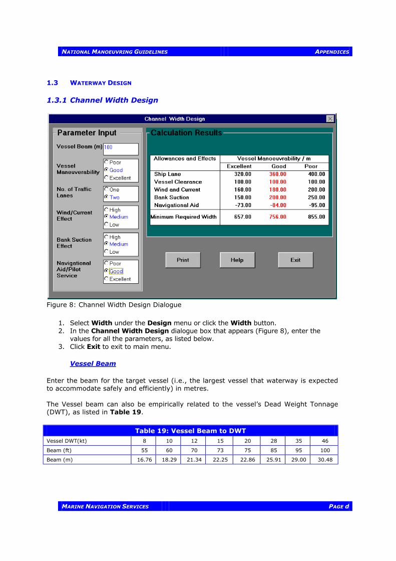
1.3 WATERWAY DESIGN 1.3.1 Channel Width Design
Figure 8: Channel Width Design Dialogue
1. Select Width under the Design menu or click the Width button. 2. In the Channel Width Design dialogue box that appears (Figure 8), enter the
values for all the parameters, as listed below. 3. Click Exit to exit to main menu.
Vessel Beam
Enter the beam for the target vessel (i.e., the largest vessel that waterway is expected to accommodate safely and efficiently) in metres. The Vessel beam can also be empirically related to the vessel’s Dead Weight Tonnage (DWT), as listed in Table 19.
Table 19: Vessel Beam to DWT
Vessel DWT(kt) 8 10 12 15 20 28 35 46
Beam (ft) 55 60 70 73 75 85 95 100
Beam (m) 16.76 18.29 21.34 22.25 22.86 25.91 29.00 30.48
APPENDICES NATIONAL MANOEUVRING GUIDELINES
PAGE e MARINE NAVIGATION SERVICES
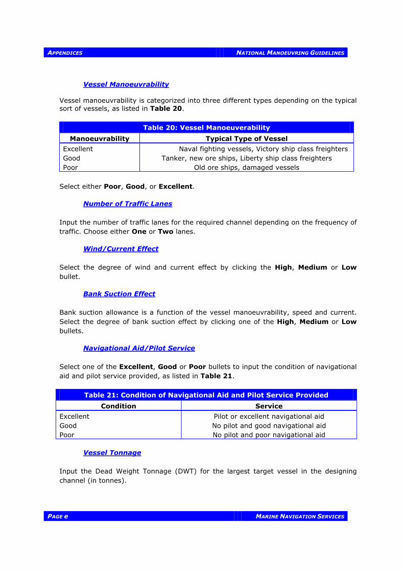
Vessel Manoeuvrability Vessel manoeuvrability is categorized into three different types depending on the typical sort of vessels, as listed in Table 20.
Table 20: Vessel Manoeuverability
Manoeuvrability Typical Type of Vessel
Excellent Naval fighting vessels, Victory ship class freighters Good Tanker, new ore ships, Liberty ship class freighters Poor Old ore ships, damaged vessels
Select either Poor, Good, or Excellent. Number of Traffic Lanes Input the number of traffic lanes for the required channel depending on the frequency of traffic. Choose either One or Two lanes.
Wind/Current Effect Select the degree of wind and current effect by clicking the High, Medium or Low bullet.
Bank Suction Effect
Bank suction allowance is a function of the vessel manoeuvrability, speed and current. Select the degree of bank suction effect by clicking one of the High, Medium or Low bullets. Navigational Aid/Pilot Service
Select one of the Excellent, Good or Poor bullets to input the condition of navigational aid and pilot service provided, as listed in Table 21.
Table 21: Condition of Navigational Aid and Pilot Service Provided
Condition Service
Excellent Pilot or excellent navigational aid Good No pilot and good navigational aid Poor No pilot and poor navigational aid Vessel Tonnage
Input the Dead Weight Tonnage (DWT) for the largest target vessel in the designing channel (in tonnes).

NATIONAL MANOEUVRING GUIDELINES APPENDICES
MARINE NAVIGATION SERVICES PAGE f
1.3.2 Waterway Depth Design
Figure 9: Waterway Depth Design Screen
1. Select Depth under the Design menu or click the Depth button. 2. In the Waterway Depth Design dialogue box that appears (Figure 9), enter the
values for all the parameters, as listed below. 3. Click on the Exit button to exit to the main menu.
Maximum Draught
The maximum draught for the target vessel is defined in metres. The maximum vessel draught can also be empirically related to vessel DWT as listed in Table 22.
Table 22: Vessel Draught to DWT
Vessel DWT (kt) 8 10 12 15 20 28 35 46

APPENDICES NATIONAL MANOEUVRING GUIDELINES
PAGE g MARINE NAVIGATION SERVICES
Draught (ft) 24 29 30 32 33 35 36 39
Draught (m) 7.32 8.84 9.14 9.75 10.06 10.67 10.97 11.89

NATIONAL MANOEUVRING GUIDELINES APPENDICES
MARINE NAVIGATION SERVICES PAGE h
Vessel Length
Input the length for the target vessel in metres. The vessel length can also be empirically related to vessel DWT, as listed in Table 23.
Table 23: Vessel Length to DWT
Vessel DWT (kt) 8 10 12 15 20 28 35 46
Length (ft) 450 470 500 525 575 625 700 750
Length (m) 137.16 143.26 152.4 160.02 175.26 190.50 213.36 228.6
Vessel Speed
Enter the design (limit) speed of vessels in the channel in knots. If the vessel speed is in metres per second (m/s), the conversion factor is: 1 knot = 0.5144 m/s. Bottom Material Input the properties for channel bottom material. The Hard, Medium and Soft type of bottom materials represent, respectively:
Hard Hard ground (as rock) Moderate Moderate hard ground (as sand) Soft Soft ground (as silt or soft clay)
Select one of the Hard, Moderate, and Soft bullets. Exposure Condition
Input the exposure condition for the channel by selecting Fully, Medium or Unexposed based on the actual channel condition. Fresh/Salt Water Select either fresh water (for rivers) or salt water as the input parameter. Ratio of Channel Width/Vessel Beam Input the ratio of channel width/vessel beam. 1.3.3 Channel Bank Slope Design To input parameters for bank slope design:
1. Select the type of material from the list on the screen. 2. The suggested slope will appear on the right highlighted in yellow. 3. Click on the Exit button to exit to the main menu.

APPENDICES NATIONAL MANOEUVRING GUIDELINES
PAGE i MARINE NAVIGATION SERVICES
Figure 10: Channel Bank Slope Design Screen 1.3.4 Channel Bend Design
Figure 11: Channel Bend Design Screen

NATIONAL MANOEUVRING GUIDELINES APPENDICES
MARINE NAVIGATION SERVICES PAGE j
To input parameters for channel bend design:
1. Select Channel Bend under the Design menu or click the Bend button. 2. In the Channel Bend Design Dialogue box that appears (Figure 11), enter the
values for all the parameters, as listed after Figure 11. 3. Click on the Exit button to exit to the main menu.
Select the values for Vessel Manoeuvrability and Number of Manoeuvre Lanes following the same procedure previously described in Channel Width Design. As well, select the values for Vessel Speed and Vessel Length following the same procedure previously described in Waterway Depth Design. If the values have been selected in the Width or Depth Design, they are automatically transferred to the same items in Channel Bend Design.
Turn Angle of Bend The turn angle of channel bend is defined in degrees. Radius of Curvature The radius of curvature of channel bend is related to the turn angle, as listed in Table 24.
Table 24: Curvature of Channel Bend to Turn Angle
Angle of Turn (degrees) Radius of Curvature
Less than 25° 3 L 25° - 35° 5 L 35° - 55° 8 L Greater than 55° 10 L where L is the length of the target vessel in metres.
Unobstructed Sight Distance The unobstructed sight distance from the bridge of the target vessel is defined in metres. Note: A minimum of 2 446 m is required. If the distance is unknown, enter 2 446 m which is the
minimum required.
1.4 VIEWING AND PRINTING DESIGN SUMMARY To view, select Results Summary under the Design menu. The overall design results will be shown in a summarised form as follows:

APPENDICES NATIONAL MANOEUVRING GUIDELINES
PAGE k MARINE NAVIGATION SERVICES
Figure 12: Results Summary Screen Layout To print, select Print from the File menu and click OK. 1.5 QUITTING To Quit, select Exit under the File menu or click the Quit button below the main menu to quit this application.


NATIONAL MANOEUVRING GUIDELINES APPENDICES
MARINE NAVIGATION SERVICES PAGE k
APPENDIX 2
WATERWAY DESIGN
SOFTWARE USERS MANUAL VERSION 2

NATIONAL MANOEUVRING GUIDELINES APPENDICES
MARINE NAVIGATION SERVICES PAGE l
2.1 SOFTWARE INSTALLATION When installing:
1. Insert the 3.5’’ Waterway Design Software Diskette into drive A: (or drive B:). 2. Select Run from the File menu in Program Manager window. 3. In the Run dialogue box that appears, type a:\setup (or b:\setup), then click the
OK button.
2.2 FILE MANAGEMENT 2.2.1 Opening a File When using an existing file:
1. Choose Open from the File menu. 2. In the Open File dialogue box that appears, select and double click the proper
directory containing the file to be opened. 3. Select the file from the file list, then click OK (or double click the file name from the
file list). When using an new file, choose New from the File Menu. 2.2.2 Saving A File If an existing file is opened and modified, the file can be saved using Save or Save As. In case of opening a new file, it can be saved using Save As only. When saving an existing file under the original name, choose Save from the File menu. When saving an existing file under a different name, or when saving a new file:
1. Choose Save As under the File menu. 2. In the Save As dialogue box that appears, select and double click the proper
directory where the file will be saved. 3. Enter the file name under the text box File to be Saved As. 4. Choose the OK button.
2.2.3 Deleting a File When deleting a file:
1. Choose Delete under the File menu. 2. In the Delete File dialogue box that appears, select and double click the proper
directory containing the file to be deleted. 3. Select the file from the file list, then click OK (or double click the file name from the
file list). 2.2.4 Closing a File
Choose Close under the File menu.

NATIONAL MANOEUVRING GUIDELINES APPENDICES
MARINE NAVIGATION SERVICES PAGE m
2.3 WATERWAY DESIGN 2.3.1 Channel Width Design
Figure 13: Channel Width Design Dialogue
1. Select Width under the Design menu or click the Width button. 2. In the Channel Width Design dialogue that appears (Figure 13), enter the values
for all the parameters, as listed below. 3. Click Exit to exit to main menu.
Vessel Beam
Enter the beam for the target vessel (i.e., normally the largest vessel that waterway is expected to accommodate safely and efficiently) in metres. The Vessel beam can also be empirically related to the vessel’s Dead Weight Tonnage (DWT), as listed in Table 25.

NATIONAL MANOEUVRING GUIDELINES APPENDICES
MARINE NAVIGATION SERVICES PAGE n
Table 25: Vessel Beam to DWT
Vessel DWT(kt) 8 10 12 15 20 28 35 46
Beam (ft) 55 60 70 73 75 85 95 100
Beam (m) 16.76 18.29 21.34 22.25 22.86 25.91 29.00 30.48
Vessel Manoeuvrability Vessel manoeuvrability is categorized into three different types depending on the typical type of vessels, as listed in Table 26. Select either Poor, Good or Excellent.
Table 26: Vessel Manoeuverability
Manoeuvrability Typical Type of Vessel
Excellent Naval fighting vessels, Victory ship class freighters Good Tanker, new ore ships, Liberty ship class freighters Poor Old ore ships, damaged vessels
Number of Traffic Lanes
Input the number of traffic lanes for the required channel depending on the frequency of traffic. Choose either One or Two lanes. Traffic Density Encounter traffic density shall be considered in two-way traffic channels. Additional width is required for channels with heavy traffic density. Select the degree of traffic density by selecting the Light, Moderate or Heavy bullet.
Light 0 - 1 vessel/hour Moderate 1 - 3 vessel/hour Heavy > 3 vessel/hour
Crosswind Effect Select the degree of crosswind effect by selecting Mild, Moderate or Severe.
Mild < 15 knots Moderate 15 - 33 knots Severe > 33 knots
Cross Current Effect
Select the degree of cross current effect by selecting the Negligible, Low Moderate, or Severe bullet.
Negligible < 0.2 knots Low 0.2 - 0.5 knots Moderate 0.5 - 1.5 knots Severe > 1.5 knots

NATIONAL MANOEUVRING GUIDELINES APPENDICES
MARINE NAVIGATION SERVICES PAGE o
Bank Suction Effect Bank suction allowance is a function of the vessel manoeuvrability, speed and current. Select the degree of bank suction effect by clicking the High, Medium or Low bullet.
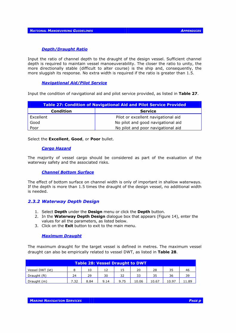
NATIONAL MANOEUVRING GUIDELINES APPENDICES
MARINE NAVIGATION SERVICES PAGE p
Depth/Draught Ratio Input the ratio of channel depth to the draught of the design vessel. Sufficient channel depth is required to maintain vessel manoeuverability. The closer the ratio to unity, the more directionally stable (difficult to alter course) is the ship and, consequently, the more sluggish its response. No extra width is required if the ratio is greater than 1.5.
Navigational Aid/Pilot Service Input the condition of navigational aid and pilot service provided, as listed in Table 27.
Table 27: Condition of Navigational Aid and Pilot Service Provided
Condition Service
Excellent Pilot or excellent navigational aid Good No pilot and good navigational aid Poor No pilot and poor navigational aid
Select the Excellent, Good, or Poor bullet. Cargo Hazard The majority of vessel cargo should be considered as part of the evaluation of the waterway safety and the associated risks. Channel Bottom Surface The effect of bottom surface on channel width is only of important in shallow waterways. If the depth is more than 1.5 times the draught of the design vessel, no additional width is needed. 2.3.2 Waterway Depth Design
1. Select Depth under the Design menu or click the Depth button. 2. In the Waterway Depth Design dialogue box that appears (Figure 14), enter the
values for all the parameters, as listed below. 3. Click on the Exit button to exit to the main menu.
Maximum Draught
The maximum draught for the target vessel is defined in metres. The maximum vessel draught can also be empirically related to vessel DWT, as listed in Table 28.
Table 28: Vessel Draught to DWT
Vessel DWT (kt) 8 10 12 15 20 28 35 46
Draught (ft) 24 29 30 32 33 35 36 39
Draught (m) 7.32 8.84 9.14 9.75 10.06 10.67 10.97 11.89
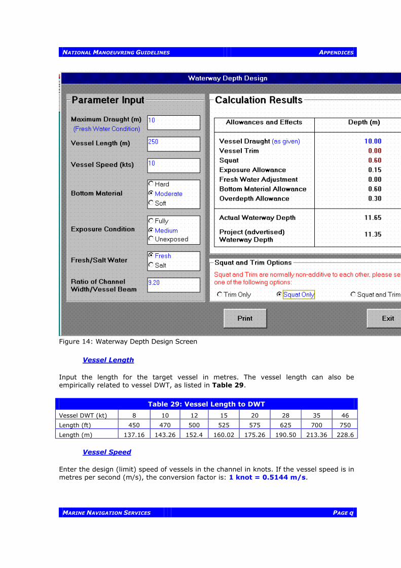
NATIONAL MANOEUVRING GUIDELINES APPENDICES
MARINE NAVIGATION SERVICES PAGE q
Figure 14: Waterway Depth Design Screen
Vessel Length
Input the length for the target vessel in metres. The vessel length can also be empirically related to vessel DWT, as listed in Table 29.
Table 29: Vessel Length to DWT
Vessel DWT (kt) 8 10 12 15 20 28 35 46
Length (ft) 450 470 500 525 575 625 700 750
Length (m) 137.16 143.26 152.4 160.02 175.26 190.50 213.36 228.6
Vessel Speed
Enter the design (limit) speed of vessels in the channel in knots. If the vessel speed is in metres per second (m/s), the conversion factor is: 1 knot = 0.5144 m/s.

NATIONAL MANOEUVRING GUIDELINES APPENDICES
MARINE NAVIGATION SERVICES PAGE r
Bottom Material Input the properties for channel bottom material. Select one of the Hard, Moderate, and Soft bullets. They represent:
Hard Hard ground (as rock) Moderate Moderate hard ground (as sand) Soft Soft ground (as silt or soft clay)
Exposure Condition
Input the exposure condition for the channel by selecting Fully, Medium or Unexposed based on the actual channel condition. Fresh/Salt Water Select either fresh water (for rivers) or salt water as the input parameter. Ratio of Channel Width/Vessel Beam Input the ratio of channel width/vessel beam. 2.3.3 Channel Bank Slope Design To input parameters for bank slope design:
1. Select the type of material from the list on the screen. 2. The suggested slope will appear on the right highlighted in yellow. 3. Click on the Exit button to exit to the main menu.

NATIONAL MANOEUVRING GUIDELINES APPENDICES
MARINE NAVIGATION SERVICES PAGE s
Figure 15: Channel Bank Slope Design Dialogue

NATIONAL MANOEUVRING GUIDELINES APPENDICES
MARINE NAVIGATION SERVICES PAGE t
2.3.4 Channel Bend Design
Figure 16: Channel Bend Design Dialogue
1. Select Channel Bend under the Design menu or click the Bend button. 2. In the Channel Bend Design Dialogue that appears (Figure 16), enter the values
for all the parameters, as listed below. 3. Click on the Exit button to exit to the main menu.
Select the values for Vessel Manoeuvrability and Number of Manoeuvre Lanes following the same procedure previously described in Channel Width Design. Select the values for Vessel Speed and Vessel Length following the same procedure previously described in Waterway Depth Design. If the values have been selected in the Width or Depth Design, they are automatically transferred to the same items in Channel Bend Design. Turn Angle of Bend The turn angle of channel bend is defined in degrees.

NATIONAL MANOEUVRING GUIDELINES APPENDICES
MARINE NAVIGATION SERVICES PAGE u
Radius of Curvature The radius of curvature of channel bend is related to the turn angle:
Table 30: Channel Bend to Turn Angle
Angle of Turn (degrees) Radius of Curvature
Less than 25° 3 L 25° - 35° 5 L 35° - 55° 8 L Greater than 55° 10 L where L is the length of the target vessel in metres.
Unobstructed Sight Distance The unobstructed sight distance from the bridge of the target vessel is defined in metres. (Note: A minimum of 2 446 m is required. If the distance is unknown, enter 2 446 m.) 2.4 VIEWING AND PRINTING DESIGN SUMMARY To view, select Results Summary under the Design menu. The overall design results will be shown in a summarised form is shown in Figure 17. To print, Select Print from the File menu

NATIONAL MANOEUVRING GUIDELINES APPENDICES
MARINE NAVIGATION SERVICES PAGE v
Figure 17: Results Summary Screen Layout 2.5 QUITTING
Select Exit under the File menu or click the Quit button below the main menu to quit this application.

NATIONAL MANOEUVRING GUIDELINES APPENDICES
MARINE NAVIGATION SERVICES PAGE w
APPENDIX 3
SAMPLE CALCULATIONS

NATIONAL MANOEUVRING GUIDELINES APPENDICES
MARINE NAVIGATION SERVICES PAGE x
3.1 SAMPLE CALCULATION FOR CHANNEL WIDTH (USING VERSION 1) Sample Input:
1) Vessel Beam (m) = 30.48 2) Vessel Manoeuvrability = Excellent 3) No. of Traffic Lanes = Two 4) Wind/Current Effect = Low 5) Bank Suction Effect = Medium 6) Navigational Aids/Pilot = Good
Width Calculation: Manoeuvring Lane Width 1.6 B 48.77 x 2 Hydrodynamic Interaction Lane 100 Ft 30.48 Wind/Current Requirement 0.6 B 18.29 x 2 Bank Suction Requirement 0.75 B 22.86 x 2 SUB-TOTAL 210.32 Navigational Aids/Pilot @ -10% -21.03 TOTAL 189.28 m Therefore, the total width required for the channel is 189.28 m. 3.2 SAMPLE CALCULATION FOR CHANNEL DEPTH Sample Input:
1) Vessel Draught (m) = 9.14 2) Vessel Length (m) = 213.36 3) Vessel Speed (m/s) = 4.572 4) Bottom Material = Soft 5) Exposure Condition = Medium 6) Fresh/Salt Water = Fresh 7) Ch. Width / Vessel Beam = 189.28/30.48
Therefore, W = 6.2 B Depth Calculation: Vessel Draught (m) 9.14 Vessel Trim (m) 0.0025 x L 0.53 Squat (see calculation below) 0.54 Exposure Allowance 0.15 Fresh/Salt Water Adjustment 0.00 Bottom Material Allowance 0.25 Overdepth Allowance 0.30 ACTUAL CHANNEL DEPTH 10.91 m Therefore, the project channel depth = TOTAL - Overdepth Allowance = 10.91 - 0.3 = 10.61 m

NATIONAL MANOEUVRING GUIDELINES APPENDICES
MARINE NAVIGATION SERVICES PAGE y
Squat Calculation:
[ ]Z(d/D )=a[v / gd] D / d F2s
b cw
Table 31: Squat Calculation
Variable Description of Variable Value
d vessel draught, (m) 9.14
D project channel depth, (m) *
vs vessel speed, (m/s) 4.572
g gravity acceleration (m/s2) 9.81
Fw channel width factor;
= wF = 3.1W / B
where W < 9.61 B
= 1 where W > 9.61 B
1.245
a common coefficient 0.298
b common coefficient 2.289
c common coefficient -2.972
* Suppose: D = 1.2 x d = 10.968 m
Z = 0.2984572
981 914
10968914
10968 1245
0537
2 289 1 972.( . )( . )
.
. ( . ) ( . )
. ( )
. .
=
−
m see above
Now, using the project channel depth: D = 10.61 m in the equation above: Z = 0.539 m TOTAL = 10.91 m Project Channel Depth = 10.91 - 0.3 = 10.61 m Therefore, the project channel depth required is 10.61 m. 3.3 SAMPLE CALCULATION FOR CHANNEL BEND Sample Input:
1) Vessel Length (m) = 213.36 2) Turn Angle of the Bend = 25° 3) Radius of Curvature (m) = 1000 4) Vessel Speed (m/s) = 4.572 5) Vessel Manoeuvrability = Excellent 6) No. of Traffic Lanes = Two

NATIONAL MANOEUVRING GUIDELINES APPENDICES
MARINE NAVIGATION SERVICES PAGE z
7) Unobstructed Sight Distance (m) = 2446 Minimum radius of curvature = 5 x L = 1066.8 m Minimum straight length requirement between curves = 5 x L = 1066.8 m To calculate the increase in the channel width:
SCRFLv0.9144=W
ct
22sφ
∆
Table 32: Channel Width Calculation
Variable Description of Variable Value
∆W increase in the ship lane width, (m)
f angle of bend, degrees 25
vs speed of ship in channel relative to the bottom, (kts) 8.9
L "target" vessel length, (m) 213.36
Rt turning radius, (m) 1066.8
Cc coefficient of vessel manoeuvrability (turning ability) (poor=1; good=2; Excellent=3)
3
S unobstructed sight distance from the bridge of the
ship, (m)
2446
F 1.0 for one-way traffic; 2.0 for two-way traffic 2
Therefore, using the above formula, ∆W = 21 m Minimum straight length for width variation = 10 × ∆W = 210 m