CANADA Handson 1987 MAY Election - American … Bi- County Boulevard Suite B -11 Farmingdale, NY...
100
Handson Election THE MAG AZINE FOR THE ELECTRONICS ACTIVIST! I Add this depth -perception feature to your scope! $2.50 U.S. $2.95 CANADA MAY 1987 48784 SINCLUDING 12 -PAGE R GAJX 3D OSCILLOSCOPF J AMPLIFIERS Need a special circuit? You can design your own. J ARMS & TURNTABLES IlInside the science of sound. DECODERDRI VER DEMONSTRATOR You can watch it work! NIGHT OWL Add a Remote (m Add a Security System A touch switch for those who cannot reach. - o 71 896 05 48784III8 :0'
Transcript of CANADA Handson 1987 MAY Election - American … Bi- County Boulevard Suite B -11 Farmingdale, NY...

Handson Election THE MAG AZINE FOR THE ELECTRONICS ACTIVIST!
I Add this depth -perception feature to your scope!
$2.50 U.S.
$2.95 CANADA MAY
1987
48784
SINCLUDING 12 -PAGE
R GAJX
3D OSCILLOSCOPF
J
AMPLIFIERS Need a special circuit?
You can design your own.
J
ARMS & TURNTABLES
IlInside the science of sound.
DECODERDRI VER
DEMONSTRATOR You can watch it work!
NIGHT OWL
Add a Remote (m Add a Security
System
A touch switch for those who cannot reach.
- o 71 896
05
48784III8 :0'

IS COMING IN MAY
. , . ' . '. t`'4.! ̀ .. .
t., ., .'.
PMP°ce a vNF
ezáa 1Pe
NpÓM N v' vOp ÉHQS Qr°oe; r ÑE FpA
`et Ñ`¡1ÁPP'°<
Gó e u se
óé áPP N 1°µs
N°1gau°Ñt. °a
V ápß 1 ° e P°kt° 15
An electronics revolution is in the making, but you don't have to wait until 2001 to find out how it will change your life in
the 21st century. Radio -Electronics will forecast the coming changes and how they will affect you in the May 1987 issue!
Created by a special editorial task force-two years in prepa- ration -this unique issue, 2001, takes you into the research
laboratories of Westinghouse, Texas Instruments, Ford and Bell Labs where the future is being invented today!
You'll get an advance look at what's coming in artificial intelligence... new cars and highways (cleaner, quieter and more efficient)... futuristic energy sources like magneto- hydro- dynamic and particle -beam generators... personal commu- nications systems that will give you instant access to anyone anywhere... super computers and teaching breakthroughs that will multiply your capacity to learn!
Arthur Clarke introduces 2001. Isaac Asimov explores the
marvels of robotics. But it is not science fiction. Rather it is
emerging technology with a solid foundation in current re-
search and development.
And its impact will be enormous It will change the way you
work... me way you pink... the way you live!
2001 is the kind of special publishing Event that can only happen once in any magazine's lifetime and it will happen to Radio -Electronics in May, 1987.
With extra features and extra pages, 2001 will bear a pre-
mium cover cost, but you can reserve your copy now at less
than the regular cover cost by mailing any one of the sub-
scription orders in this issue.
2001 is coming in May. Make sure now that you don't miss it!
Radio- Electrodes R

apds
33
41
45
25
61
77
62
83
67 70
75
80
26
32 88
92 90 94
95
2
4
8
18
49
73
39
INCLUDING 12 -PAGE GADO
ICS Volume 4, No. 5 May 1987
SPECIAL FEATURES 3 -D Oscilloscope -add depth -perception to your troubleshooting arsenal Smoke /Security Alarm -two ways to improve your smoke detector Smoke Buster -add a remote sensor to your smoke /fire alarm
FEATURETTES Stronger Magnet -to study electronic material Hands -on Report /Fluke Model 52K /J Thermometer -It's computerized! Hands -on Report /Micro Match -interface details on connecting many
types of computers and peripherals
THEORY AND CIRCUITS Arms and Turntables -do more than just spin the tune Electronic Fundamentals -what you need to know about basic amplifier
design
CONSTRUCTION Decoder /Driver Demonstration -seeing is believing (and learning) Night Owl -a touch switch for those who cannot reach
Serial Bus Switch -for the Commodore -64 Pilot Carrier Frequency Standard -lets you pluck an accurate signal
frequency out of thin air
SPECIAL COLUMNS Friedman on Computers- modernized communications Jensen on DX'ing -the unknown becomes known to you
Carr's Ham Shack -MMIC wideband amplifiers Circuit Circus- non -standard amplifier circuits Ellis on Antique Radios -curing that uncontrollable hum Saxon on Scanners -mobile scanning Wels' Think Tank -we keep serving them up!
DEPARTMENTS Editorial -the assault on the battery Letter Box -find out what your fellow readers have to say New Products Showcase -here's what's new Bookshelf -an information round -up Gadget -the newsletter for grown -up kids
Blanket with a Brain -Quantum's Cordless Automatic; It's In Your Hands -The Porta Copy; Big Feature, Low Price-Realistics' Linear Drive Turntable; Double Your Pleasure- Sharp's Dual Cassette System; Music Maker -Tascam Porta Studio; Dated Picture Taking- Canon's Tele Date; Shave On the Run -Braun's Pocket Razor
FactCards -we dig -up the data so you don't have to Free Information Card -they'll get back to you pronto
Smoke Entry Alarm -page 41
Saxon On Scanners -page 94
New Therrrometer -page 61
Matching Guide -page 77
Nite Owl-page 70
AAA 3D Scope Pics -page 33 1

2
The Magazine for the Electronics Activist!
The assault of the battery!
Christmas has passed and I'm still paying for it! No, I didn't ring up a big tab on my credit cards. What is still ringing up a humongous debt in the family's budget is the replacement cost of batteries for motorized toys and gadgets.
The replacement cost of batteries is $2 billion -plus in the North American consumer market. Where do all those batteries go? The entry of ultra -technologies into our Christmas givings is one explanation; more so, our society is highly mobile, the need for reliable portable devices throughout our entire living experience has channeled battery distribution into our food supermarkets, drug outlets, discount suppliers, and newsstands. The fact is that when I surveyed my home, finding batteries in smoke alarms, cameras, calculators, kitchen clock, tape recorder, power tools, radios, watches...(I could go on), the total replace- ment cost for all types of batteries in use was $263, plus local sales tax. That amount is larger than my family milk bill for the year!
Due to the evolution of quartz timing mechanisms, clocks and watches are among the largest users of batteries. In 1984, less than 1.2 per cent of the clocks purchased did not use batteries. All the clocks sold since, and still in service, require battery replacement at least once a year. Over 60 million watches were sold last year that require battery replacement at least once a year -some, twice a year.
The average household purchased 14 batteries a year in 1981. Today, 27 batteries are purchased -which is not typical of my household! I won't forecast next year's usage. Why the growth? The new -product market is a big battery mover. This year, more than 12- million radios will be sold requiring at least one battery. More than 30- million battery- operated tape units will hit the streets this year -each is a battery gobbler. The growth of bat- tery- operated toys need not be explained. Quartz time pieces, cordless phones, the old- fashioned flashlight, portable power tools, briefcase computers, pocket pagers -who can list them all?
This year and the years to come will see an increased interest by consumers for more efficient batteries, both in usable output and price. Rechargeable batteries and recharging devices will see increased sales. Designers will be looking toward building complete products with an internal battery supply and charging feature. We are living in a battery revolution that is dynamic and forecasts indicate cost -saving improvements for the future. After all, $2- billion -plus can buy a lot of milk and cookies!
Julian S. Martin, KA2GUN Editor
L
Volume May
4, No. 5
1987
Larry Steckler, EHF. CET Editor -In -Chief & Publisher
Art Kleiman, editorial director
Julian S. Martin, KA2GUN, editor
Robert A. Young, associate editor Herb Friedman, W2ZLF, associate editor
John J. Yacono, associate editor
Brian C. Fenton, associate editor
Carl Laron, associate editor
Byron G. Wels, K2AVB, associate editor
M. Harvey Gernsback, contributing editor
Teri Scaduto Wilson, editorial assistant
Ruby M. Yee, production director
Karen S. Tucker, production manager
Robert A. W. Lowndes, editorial associate
Geoffrey S. Weil, production assistant
Jacqueline R Cheeseboro, circulation director
Arline R. Fishman, advertising director
BUSINESS AND EDITORIAL OFFICES Gernsback Publications, Inc. 500 Bi- County Boulevard Farmingdale, NY 11735. 516,293 -3000 President: Larry Steckler Vice -president: Cathy Steckler
NATIONAL ADVERTISING SALES (For Advertising Inquiries Only) Joe Shere MIDWEST PACIFIC 1507 Bonnie Doone Terrace Corona Del Mar, CA 92625 714/760-8697
Alan Berg EAST /SOUTHEAST 11 Manor Drive Marlboro. NJ 07746 212i603 -9510
Larry Steckler, Publisher 500 Bi- County Boulevard Suite B -11
Farmingdale, NY 11735 516-293-3000
Composition by Cover photography by Mates Graphics Dan Muro
ASO
1' , tnsrnwndMp applied tot:
Hands-on Electronics, ¡ISSN 0743-2968) Published monthly by Gernsback Publications. Inc . 500 Bì-County Boulevard. Farm ingdaie. NY 11735 Second Class postage paid al Farmingdale, NY and al additional mailing offices One-year twelve issues. subscnp- lion rate U S and possessions 528.00. Canada 533 00. all other countries 535 50 Subscrption orders payable in U S funds only. International Postal Money order or check drawn on a U S bank U S single copy price 52 50 c 1987 by Gernsback Publications. Inc Ail rights reserved Printed in U S A
Postmaster Please send address changes to Hands-On Elec- tronics, Subscription Dept PO Box 338, Mount Morns. IL 610549932
A stamped sell addressed envelope must accompany all submitted manuscripts and or artwork or photographs it their return is desired should they be relected. We disclaim any responsibility for the loss or damage of manuscrpts and o, artwork or photographs while an
our possession or otherwise
As a servato to readers. Hands-on Electronics publishes available plans or information relating to newsworthy products. techniques and scientific and technological developments Because of possi- ble variances an the quality and condition of materials and work- manship used by readers. Hands-on Electronics disclaims any responsibility for the safe and proper functioning of reader-bulll projects based upon or hum plans Of information published In this magazine

(li .J r r OM i. A e _`_ ___ _ C O R P O R A T I O N j
1- 800 -344 -453 9 AK, Puerto Rico - 218- R1 {674 TW 6267791 FA% 216 681 3309 TW I( 9103600962 DIGI KEY CORP iii NATIONAL SEMICONDUCTOR PANASON )IODES DIAMOND TOOL UNGAR
OKMACHINEEWC INC. NTERSIL AD 256K (262,144 x 1) 0RAM 150NS $5.7011; $39.95I9 ES CWINDUSTRIES AMDEK G.E. V/S4 EAC, INC. J. W. MILLER AAVID ENGINES NEVI JGAR YAGEO J. W. MILLER LUXO 0
.Y M E. F. JOHNSON ATLANTIC SEMICONDUC' 1^'+^ Factory Firsts CHEMICALS PLESSV.......
INTEGRATED CIRCUITS INTEGRATED rma
1 M1 1t
.
CIRCUITS SOLDER TAIL DIP SOCKETS ." . a.1. e..r.
011101 0040 7174 DI 0037.
RN Y . -r.,- Im..w
u.u. ,n1 MAT MOM Y rwrr
am 0 120 0 OD W Ilo
14 04,0104. au
uau u goad . u rr
No wu 74 7 SO 21 OD ."'.euro u r U
WIRE WRAP my SOCKETS ' ar,rM1a u,..rr+,ree r r.0u+r
3C ARIES
y p
Pew °' aq DO 0 6 0 o 77 WO 6 0 .00 a
of WO 6 0
TANTALUM CAPACITORS
VI 18 1 vo On 44 ti
r 0 n 1 Is 62 4 441 ara
.
, 160 1 16 2 V .
- .-
ND, 11I
. .. .
.. ..
,
.
.
-
...
.
-
.
.
.^
.. .
. .
w. r
..
.
. r
r
.
swan
C. MO6
sr .
wee
.. . - '
'
.
, -JRkk -1 6 -{--i.1-1 .,Tr.
n 4 , 7404 . . Nov R r
lbYrw,,m. nM0l' sr wai. NON 100
'
M.. , r
.
.
n r
.
r
tl
a - .
NNO tla .pf
100 7 23
r 1603i
aatl
f wp~ Fgnn 7 w17,7000 N
On f ó..e...r. M . ¢ 07006 00
IN t 1
4 100 10 .2 75 N PO 107 0 1rnso
.00 1410 .01 10 10 4 64 3011 326 0 ZINN
7 á0 p ie we A
w 013 0 wy tl w 1110
ID WON C44.54. MN *Oar Pore,. a w,
1
I. w MuPS10- NO
1M r 7.0 F Fi,d R v1a. A. ..... ,,. ..
4tiER r 4 .r
t .
r i1='en.-pM.« 'w M
.. 6- sMY4Nrw
400 14 07
un mi ur. rro0rwr rw wr r 0064..r aerña CAT NO
"tannin
ér rams. NWT Or RIT
110 016C <u7oes °24°
ow
ÿY. ~~.rr.. re. .ur,rö noeum uvr
In e 6'' rw rro tl i
. .." 4144$ 611101 A.
. .
.
..aM.Tt
- "
. . .
..
+
Mbe.r..
.
h ...
. .
_-
4.4 11 II
070 1000 - - GM
1 70 252 110 RI 10 MO H r
Ó 705 51176 Wm f! á Á rtl Mn a l iñ n áñ
PO D
PANASONIC LS SERIES
e 1N
ú n
0
m D
INN 1 n.
.
m
La.a
,E j,-,1 i 1 AMP SILIC()NNIC1nIFfiti
r M 41 --enrNM 4. 4
..I w r x M . . w, , ..
ruM r6r1M1r.r.r. 54a
r.r .wy. I 111 0 1¡:
' á ^
E a : ú
n: Vi 7m á
sé a
1.1124 Uri. 250 11 77 2 A 610 ro 1111
52214 no 27 34. 2111 NZ PS76
1.10 DO 1 0 1 01 60 77O2 WM
- _ -- . no M CAT NO 1GA9 6
v.1ur E e11 J9 PANASONIC V SERIES
.r.... .. ...+ ^4404Cr
prr.raC..ry ewr os
krrrr.r,ru1C '''...........,M...,,
1 ,ar raar.r nu 0
+wrr.+r...
vr1
AIIrA
rr.
'
erartle eY epr
m
pl
no
4
LI
cam 0t1 S f Metal O.rdn Film Resistrrr.
a, .. . .. 09
-- MIMI ;p 3.1 ew1 .. --
su. wpsee 70.47
. á.r .. r .. x 1 u0 1..,. m. .",..'&>::". 1ó:r
w`r .1r .
, n
®
II; -
tl
tl r
41a
i rr rrx
7,440
..
.
.
,.cm CA.<ts
,.
... ..
. r.
., r
`
AP"' 4tl rerxe 4a
nera Ow MN lo
1. n f. .p w. 41 NOS Mr, 20 Do
7`
4,414 á po°o ' .rw .woa r. ...r r'. r
i p. ...
.. . .. ....
c r ¿ u s wn n
266)
.
Sy.ç .r r r r .
. mw.
. .
M N.eue 41 r,.
ro r NW 4.1
- -r- ` .5°
m0
rm rm l f a
1.100.705---1.100 r17:rIT.'R'r;Lr#: . .. . . -..._
. .. .
1
a
wr wwr.e a.a..r we
0. . a . 206 ep¡e.r r.r 1a. 5 rent
r-. D A 07m
M4N1 roflu Na.tl
0.. e
r
.m .
ml .n. mu loe ma -. , wen
_
ú 1 IN ' ,
... "i 1
n`6 fa .V.::." ..
It 1 r tl DO 0 01 11 0 70 07 43
r ks MN o ois 11 1111 1017 410
r 1
on 0 01 14 1 N 10 71 770
16 r 0 1
40
1
Ìtl 1 000 lala
013 T1 1,30 111 0 10 40
0 «sr, o . 6m .. ..
J 10]
. ,._ wr pe tt e i
i -1000 37,-11
r. ..
ii
ÿ 411 - n
m m ]
L 210
. 0 N
, c 1,,,ie mm .
. ...
no Cat
0r. ON 9arS Th D.p e.v.Okne 0ecwm nee wont rnr9n n sonsee ro YIy MON AMss ma by D. KM may W m11mw for ..ak.1e Ptak. lune Wei an rol eaa,lulw M. Emtrlwe 0y n1 wnr. ND foam, l W pm nnWw. Ana wrong yeur ab., 1040 M 01IW eNaMe mom and apply 1W apauynM O.K. To Op 1701aIM m No non eecwnuae non TWn ep IN won. SERVICE CHARGES VOLUME DISCOUNT rhy. We pay t ulP, .1.0.016.1040046.1.1 S A. CanGS MN M..o Won CWCk Or nvn. adM cco.pMp new DO K.r 6. np AWN wrnrrn IN 600..0 U S Auua nwa,, Canada 00 M.o
s 0.00 -9 9.99 10.00 925.00
Add $2.00 Add 10.75
S 0.009 99.99 8 100 00 -4249 99
NET Less 10
MKS OSEENK 9T PNDEL EAU TEM44419E9AK. FN 218-1111 IVA IT MAIL SIND TOUR ORDER T0: DIEFIET. P.O. OM 1177. TY91 Sim fa4. M SEND. 25.00 -49.99 Add 10.50 s 250 00 1499.99 Less 15
You ,h. pay W Wok, nohy aM. Mnu Ch1y. VISA a C O O pOAOlY OIMMNTE': A.., 1..nr.. ,r. I i. ..,.wo trom Dra en 10.1 aove tnW Merton we W raplcM a re.wa 50.00999.99 Add 10.25 950000$999.99 Less 20'r .e e 7000e 011Nn OD en.1om.«p wan.own a.on near. 'YRKES SUBJECT TOCMAMGE WITHOUT NOTICE ..
110006 Up No Charge 910005 Up. Less 25
CIRCLE 6 ON FREE INFORMATION CARD

4
LJLJ
_D D)
J
LD:
Quiz Kid I would like to know how to build a
game where there are 2 teams of say 10 people each, with pushbuttons in their hands. When I ask a question, whoever presses their button first would activate a numbered light on a master board, which would indicate which player had responded first. Of course, the first per- son would latch the system not allowing anyone else to respond. I would need a clear button to reset the system for the next question. I would also like to be able to add onto the circuit if teams got bigger. -R.F, Woodside NY
Have we editors got a circuit for you! Way back when the magazine was called Special Projects. we ran an arti- cle in the winter '83 edition (that's SP
number 5). The project was called Lock - Out (on page 61) and was built of logic gates which are still available today, al- though perhaps with different pin -outs. In its basic state it can handle eight play- ers, which you can increase to meet your needs.
Speech Impediment Just a note to tell you I enjoyed your
article "Computer Controlled Voice Syn- thesizer" in the December '86 issue. had an SP0256 -Al2 in a surplus unit purchased some time ago, and always wanted to get it up and running with my Tandy Model 4 computer, so the article was a welcome sight. There are a couple of bugs that may give other readers trou- ble, so here's how I got my unit to work.
Most computers check the Centronics
pin 13 for a PAPER OUT fault. If this pin isn't low they standby. Readers should pull that line to ground to get the unit to work. Also some computer's built -in BASIC, such as the Tandy's, use the form -feed (ASCII 12) code to generate a series of carriage returns (ASCII 13). Unfor- tunately, that same code is used to pro- duce the "TO" sound. You can get the machine to generate the "TO" sound withoLt carriage returns by sending CHR$1140) to the synthesizer for that allophone. That sets a high bit which the synthesizer ignores, while the printer sees the entire byte as undefined.
These kind of practical articles that work are what makes your magazine a real asset to an experimenter. -B.F, Dayton OH
(('onrinued on page 6)
kePRO CIRCUIT MAKER
For art supplies, kits and economical equipment to produce at home professional quality print circuit boards...ask for the pro's - Kepro Circuit Systems, Inc. Kepro has been producing prototype and short run equip- ment. as well as providing PCB supplies to industrial companies for years. Their specialized experience and knowledge provides the home hobbyist an economical and convenient source of equipment and sup- plies for a professional. one -of -a -kind. printed circuit board.
Shears, etchers, sensitized and un- sensitized copperclad laminates, ar' ,oplies. kits and Keproclad...all you need to make a professional
quality printed circuit board at home and at a cost you can afford.
Kepro, your one stop source for at home PCB's.
Wnte or call Kepro for their catalog and price list 1-800-325-3878 or 1- 314 -343 -1630 (MO) 630 Axminister Drive. Fenton, MO 630262992 Kepro Circuit Systems, Inc.
ART SUPPLIES
BENCHTOP ETCHER $76500
SHEAR $390.00
ART SUPPLIES from $2 79
//I::
COPPER CLAD LAMINATES
PhOIosensiti2ed Precut copper clad Bulk packaged copper clad Full sheets Plate -Ihru copper clad
CIRCLE R ON FREE INFORMATION CARD

SCIENTIFIC
ATLANTA
UNITS
LOWEST
PRICES
ANYWHERE!
CABLE -TV
WE'LL MATCH OR BEAT ANYONE'S ADVERTISED RETAIL OR WHOLESALE PRICES!
ITEM SINGLE
PRICE 110 -UNIT PRICE
RCA 36 CHANNEL CONVERTER (CH. 3 OUTPUT ONLY) 29.95 18.00 ea.
PIONEER WIRELESS CONVERTER (OUR BEST BUY) 88.95 72.00 ea.
LCC -58 WIRELESS CONVERTER 92.95 76.00 ea.
JERROLD 450 WIRELESS CONVERTER (CH. 3 OUTPUT ONLY) 105.95 90.00 ea.
SB ADD -ON UNIT 109.95 58.00 ea.
BRAND NEW - UNIT FOR SCIENTIFIC ATLANTA Call for specifics
MINICODE (N -12) 109.95 58.00 ea.
MINICODE (N -12) VARISYNC 119.95 62.00 ea.
MINICODE VARISYNC W /AUTO ON -OFF 179.95 115.00 ea.
M -35 B (CH. 3 OUTPUT ONLY) 139.95 70.00 ea.
M -35 B W /AUTO ON -OFF (CALL FOR AVAILABILITY) 199.95 125.00 ea.
MLD- 1200 -3 (CALL IF CH. 2 OUTPUT) 109.95 58.00 ea.
INTERFERENCE FILTERS - CH. 3 24.95 1400 ea.
JERROLD 400 OR 450 REMOTE CONTROLLER 29.95 18.00 ea.
ZENITH SSAVI CABLE READY (DEALER PRICE BASED ON 5 UNITS) 225.00 185.00 ea.
SPECIFY CHANNEL 2 or 3 OUTPUT Other products available - Please Call
Quantity Item Output Channel
Price Each
TOTAL PRICE
California Penal Code rí593 -13 forbids us from shipping any cable descrambling unit to anyone residing in the state of California
Prices subject to change without notice
PLEASE PRINT
Name
Address
State _
l ; Cashier's Check
Acct N
Signature
SUBTOTAL Shipping Add $300 per unit
COD 8 Credit Cards - Add 5%
TOTAL
City
Zip __ _
_ Phone Number (
Money Order H COD Visa
-__ Exp Date
Mastercard
FOR OUR RECORDS.
DECLARATION OF AUTHORIZED USE - I, the undersigned, do hereby declare under penalty of perjury that all products purchased, now and in the future, will only be used on cable TV systems with proper authorization from local officials or cable company officials in accordance with all applicable federal and state laws.
Dated Signed.
Pacific Cable Company, Inc. 73251/2 RESEDA BLVD., DEPT. H -5 RESEDA, CA 91335
(818) 716 -5914 No Collect Calls (818) 716 -5140 IMPORTANT: WHEN CALLING FOR INFORMATION
Please have the make and model n of the equipment used in your area. Thank You
5

LETTERBOX (Continued from page 4)
Thanks for the useful advice. Quite frankly, I don't think anyone could stop us from producing more articles like the "Speech Synthesizer" with all the good response we've received.
Monitor Manual At a recent flea market I purchased a
used SBE -125M monitor scanner man- ufactured by Linear Systems. The unit seems to work just fine, but I have no operating manual for it.
My problem is trying to figure out how to program this scanner. The scanner has a plastic card that slips into a slot on the front. Numbered squares are peeled off of the card to program the channel frequency. This allows light to pass through to photoresistors to control a voltage -controlled oscillator.
Would you see if you can help me out with this? Maybe one of your readers has an operating manual and would copy the programming instructions.
I would be glad to pay for copying and postage. -B.B., Bartlett, TN
It's time to call upon you scanner peo- ple to come to the aid of a comrade in arms. If you can help this gentlemen please write him in care of the letters column.
Depressed Not Compressed First, I have to tell you how much I
have enjoyed your magazines. Over the years I have subscribed to many elec- tronics magazines and have watched them all turn into computer magazines or ones that get so complicated that they are no longer fun.
I would like your assistance in locating some parts for a construction article fea- tured in the January 1987 issue. I want to build the CD Compressor (page 69), but I do not have the materials to produce a board from the magazine page. Would it be possible to ask your other readers if
any would be able to sell me a com- pletely- etched board?
Also, I have been unable to locate a
supplier for the NE572 compander IC. I
have tried: Jameco, DigiKey, Radio Shack, Dick Smith, as well as several advertisers in your magazine. Everyone has NE570 and NE571 IC's, but no list- ing for NE572. If anyone can assist me with these requests they can contact me at: 6315 Evanston Ave., Indianapolis, IN
46220. -B.B., Indianapolis, IN
While we haven't got a supplier for the board (unless one of our readers would care to help out), the NE 572 is made by Signetics, which has two distributors in
your area: Arrow Electronics; Tel. 317/243 -9353, and Hamilton /Avnet Electronics; Tel. 317/844 -9333. If they can't tell you where to get the chip no- body can!
Bright Idea Your article in the January 1987 edi-
tion entitled "Plant a Bulb ", is reminis- cent of a similar unit I built from an idea in Radio Craft Magazine, a few years back (in the '30's). Enclosed is a diagram for the project. -D.N., Saratoga Springs, NY
Normally we don't place diagrams in the letters column, but this project is such a cutie pie we couldn't resist.
SOCKET WITH SWITCH
THE SOCKET MUST BE
SHORTED
FALSE BULB STEM LIGHT BULB
DRY SAND
HIDDEN LIGHT SOCKET
FLOWER POT
NAILED WOODEN FRAME
AC - PLUG -
No Trace in Sight Your article in the December '86 issue
"Converting the TI 99/4A Keyboard for Sinclair ZX -81 Use" aroused considera- ble interest and ire.
We had collected 3 different versions of the keyboard as referred to in the above article and all were from different Radio Shack Stores. There was no way to decipher a particular /4A version.
Thus all the detailed elaboration on cutting and jumping turned out to be an exercise of futility as each type of board carried a different trace pattern which was augmented by a pattern of jumpers on the reverse side of the board.
The obvious intent of the author is to be precise in making the new layout agree with the original. It would have been a real "Hands -on" bonus if he had shown a ZX -81 keyboard matrix and compared its nodes and designation with the TI 99 keyboard. Then instruc- tions could've followed that showed the dissident traces in need of alteration on the TI keyboard.
Can we expect some more useful In- formation- several subscriptions for your informative publication might be at stake. -C.R., Sunnyvale, CA
There is only one version of the TI 99 4A that I'm aware of, and unfor- tunately Radio Shack has stopped car- rying it, so I don't know what they may have sold you. However, there are two outlets selling the keyboard that you may wish to look into. Try Tynamic, Box 690, Hicksville, NY 11801 or Microbiz Hawaii, POB 1108, Pearl City, HI 96782.
Late Entry In regards to the "Add an RS232 Port
to Your ZX81" in the Spring '85 issue there is a problem with the version 2 PCB's. If you are not using the data ports you would not have noticed the problem. If you are using this function, then you have to make a modification to a foil trace on the PCB.
On the solder side of the PCB, pin 3 of U7 should go straight to a teed -through hole (the one directly below it). Instead it goes to a foil trace that connects to pin 14 of U7. To correct the problem cut the trace that comes from pin 3 of U7. Make sure you don't cut the portion that comes from pin 14. Then connect a jumper from pin 3 of U7 to the feed through directly below it. That will connect pin 3 of U7 to pin 16 of U1.
The data port was not working be- cause AO was tied to A2 by the above foil trace. When address 16383 was read or written to, both of these lines were high. But for address 16382, AO should have been low but was pulled high by A2, hence the data port was not working.
I am sincerely sorry fo: any inconve- nience this may have caused you. If you have any problems please let me know. -E.W. Loxterkamp, Fairborn OH
A late correction is better than none at all. Thanks for the information.
Silenced I'm a music enthusiast as well as an
electronics experimenter, so your article on building the guitar amplifier called "The Silencer" (March /April '86) was of great interest to me. Unfortunately I can't seem to obtain the LM1895 IC the proj- ect calls for. Have they become extinct? -R.Y., Sayville NY
Like the buffalo, that chip has been forsaken. However, there is a dual ver- sion, the LM1895, that you can use. Of course the pin -outs are different, but if you wish to boost the power, you can
(Continued on page 108)

Increase your knowledge about all aspects of electronics An absolutely no -risk guarantee.
Select 5 Books for only $3`)5
and get a Frcc Gift!
kltiV READING SCHEMATICS
,
MO úu REMOTE CONTROL
DEVICES
TRANSDUCER PROJECT BOOK
1536 $14.95
2665 $17.95
1999 $21.95
1503P $15.95
2825 923.95
1277P $15.95
Build a IklI,r Music
Synthesizer
- -
1909P $14.95 2755 $17.95
2622 $21.95
D11 GITAL CLOCKS
Ir,H{ 521.95
ROBOTICS
1858 $16.95
ELECTRONIC SAFETY
PROCEDURES
ooei
ve
1420
irli CTIMPUTE
BATTERY DOOM
$17.95
1992 $14.95
I ---.`.: :J
1925 $24.95
MICROPHONES
ITE
MUSTER
IC
`COOKe00K
1199P $16.95
1553 $15.95
-101 SOUND. EIGHT ,V) PON1N IC PROIF( n
1757 $24.95 2604 $24.95
tumoutimis DIRECT
CURRENT
1870 $19.95
ELECTRONIC
1625 $24.95
1987 ELECTRONICS BOOK CLUB. Blue Ridge Summit, PA 17214 All books are hardcover edilIons unless numbers are followed by a P for paperback
2675 522.95
1599P $16.95
r Elementary Electricity Elect rhr r..wM ^
2753 $23.95
values to
$126.75
TEIEPHO\I IN>t V I 1I Iu\ AM) 611'119
1964P $9.95 2707 924.95
117 PRACTICAL
IC PROJECTS vol; (A 4 REIB
1665P $17.95 2645 $16.95
Membership Benefits Big Savings. In addition to this introductory offer, you keep saving substantially with members' prices of up to 50% off the publishers' prices. Bonus Books. Starting immediately, you will be eligible for our Bonus Book Plan, with savings of up to 80% off publishers' prices. Club News Bulletins. 14 times per year you will receive the Book Club News, descrio- ing all the current selections- mains, alternates, extras -plus bonus offers and special sales, with hundreds of titles to choose from. Automatic Order. if you want the Main Selection, do nothing and it will be sent to you automatically. If you prefer another selection, or no book at all, simply indicate your choice on the reply form provided. Ironclad No-Risk Guarantee. If not satisfied with your books, return them within 10 days without obligation! Exceptional Quality. All books are quality publishers' editions especially selected by our Editorial Board.
FREE when you i:111
A Handy, Pocket -Sized Resistor and Inductor Color Code Calculator
rPuorshers P,Ces Shown)
_RESISTOR COLOR CODE
EXEC- MINES Bali CHUB P.O. Box 10, Blue Ridge Summit, PA 17214
Please accept my membership in the Electronics Book Club and send the 5
volumes circled below, plus my FREE Resistor 8 Inductor Color Code Calculator. billing me $3.95 plus shipping and handling charges. If not satisfied, I may return the books within ten days without obligation and have my membership canceled. I agree to purchase at least 4 books at regular Club prices (plus shipping /han- dling) during the next 12 months, and may resign any time thereafter.
1199P 1277P 1420 1503P 1536 1553
1683 1734 1757 1858 1870 1909P
2604 2609 2622 2625 2645 2665
Name
Address
City
State /Zip
1599P
1925
2675
Phone
1625
1984P
2707
1663
1992
2753
1665P
1999
2755
Valid for new members only Foreign applicants will receive ordering Instructions Canada must remit in U S currency. This order subject to acceptance by the Electronics Book Club
R E SP -587
CIRCLE 19 ON FREE INFORMATION CARD
8
D
Mini RS232 Line Tester If you're in the market for a low -cost,
in -line test box that instantly identifies the data and control signals being transmitted in RS232 lines, then read on.
The Atronix RS232 Mini -Test Box fea- tures dual -state LED's to indicate positive or negative voltage, show line activity, and the status of that activity. Allowing users to easily isolate problems with their cabling or equipment, it installs anywhere in the RS232 loop and requires no bat- teries or AC power.
For use with patch panels at control centers, the RS232 Mini -Test Box provides a fast and inexpensive way of checking computer and terminal equip- ment. LED's indicate the status of trans- mit data, receive data, request to send, clear to send, data set ready, carrier de- tect, and data terminal ready.
The Atronix RS232 Mini -Test Box sells for $21 (list). For more information contact Atronix, Inc., Jeffrey S. Lang. Vice President, 207R Cambridge St. Bur- lington, MA 01803; Tel. 617/273 -5595.
CIRCLE 88 ON FREE INFORMATION CARD
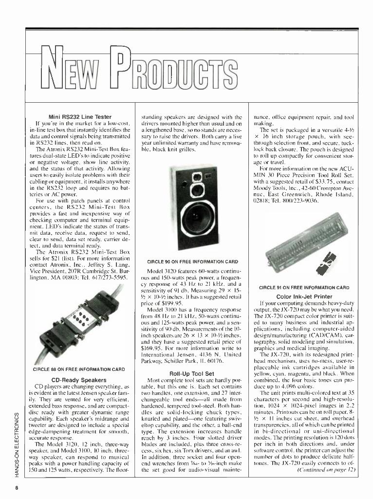
CD -Ready Speakers CD pla)crs arc changing everything, as
is evident in the latest Jensen speaker fam- ily. They are vented for very efficient. extended bass response, and are compact - disc ready with greater dynamic range capability. Each speaker's midrange and tweeter are designed to include a special edge- dampening treatment for smooth, accurate response.
The Model 3120, 12 inch, three -way speaker, and Model 3100, 10 inch, three - way speaker, can respond to musical peaks with a power handling capacity of 150 and 125 watts, respectively. The floor-
standing speakers are designed with the drivers mounted higher than usual and on a lengthened base, sono stands are neces- sary to raise the drivers. Both carry a five year unlimited warranty and have remova- ble, black knit grilles.
CIRCLE 90 ON FREE INFORMATION CARD
Model 3120 features 60 -watts continu- ous and 150 -watts peak power, a frequen- cy response of 43 Hz to 21 kHz, and a
sensitivity of 91 db. Measuring 29 x 15-
%2 X 10 -1/2 inches. It has a suggested retail price of $199.95.
Model 3100 has a frequency response from 48 Hz to 21 kHz, 50 -watts continu- ous and 125 -watts peak power, and a sen- sitivity of 90 db. Measurements of the I0- inch speakers are 26 x 13 x 10 -%2 inches, and they have a suggested retail price of $169.95. For more information write to International Jensen, 4136 N. United Parkway, Schiller Park, IL 60176.
Roll -Up Tool Set Most complete tool sets are hardly por-
table, but this one is. Each set contains two handles, one extension, and 27 inter- changeable tool ends -all made from hardened, tempered tool -steel. Both han- dles are solid -locking chuck types, knurled and plated -one featuring swiv- eltop capability, and the other, a ball -end type. The extension increases handle reach by 3 inches. Four slotted driver blades are included, plus three cross -re- cess, six hex, six Torx drivers, and an awl. In addition, three socket and four open - end wrenches from 7/64- to 3/6 -inch make the set good for audio -visual mainte-
nance, office equipment repair, and tool making.
The set is packaged in a versatile 4 -1/2
x 16 inch storage pouch, with see - through selection front, and secure, tuck - lock back closure. The pouch is designed to roll up compactly for convenient stor- age or travel.
For more information on the new ACU- MIN 30 Piece Precision Tool Roll Set, with a suggested retail of $33.75, contact Moody Tools, Inc., 42 -60 Crompton Ave- nue, East Greenwich, Rhode Island, 02818; Tel. 800/223 -9036.
CIRCLE 91 ON FREE INFORMATION CARD
Color Ink -Jet Printer If your computing demands heavy -duty
output, the JX -720 may be what you need. The JX -720 compact color printer is suit- ed to many business and industrial ap- plications, including computer -aided design/manufacturing (CAD /CAM), car- tography, solid modeling and simulation, graphics and medical imaging.
The JX -720, with its redesigned print - head mechanism, uses no -mess, user -re- placeable ink cartridges available in yellow, cyan, magenta, and black. When combined, the four basic tones can pro- duce up to 4,096 colors.
The unit prints multi -colored text at 35 characters per second and high- resolu- tion, 1024 x 1024 -pixel images in 2.2 minutes. Printouts can be on roll paper, 8- %2 X II inches cut sheet, and overhead transparencies, all of which can be printed in bi- directional or uni- directional modes. The printing resolution is 120 dots per inch in both directions and, under software control, the printer can adjust the number of dots to produce delicate half- tones. The JX -720 easily connects to of-
(Continued on page /2)

Only NRI gives you a 27" high- resolution stereo color TV you build to prepare you for
today's video servicing careers. You Build a 27" Stereo TV
During thy assembly process of your state- of-the-art Heath /Zenith 27" TV, you learn to identify and work with components and circuits as they actually appear in com- mercial circuitry Then through tests, adjust- ments, and experiments you quickly master professional troubleshooting and bench techniques.
Become one 3f America's most sought - after technicians ... put your talents and spare time to work for you in the
"explosivegrowth" world of home entertainment electronics.
Train in state -oaf -the -art video /audio ser- icing and become a fully qualified service professional the uniquely successful NRI way: It's hands -on training, at home ... designed around the latest electronic equip- ment you build and keep as part of your training.
The High -Tech Revolution in the Home Is Just Starting
Sweeping changes are taking place in our homes, changes brought about by the phenomenal growth of home entertainment electronics. Already available are high res- olution TV, TVs with stereo sound, simul- taneous multi -channel viewing, projection TV, Camcorders, 8 mm video cassettes, and compact disc players.
And the revolution has spread to the busi- ness sector as tens of thousands of com- panies are purchasing expensive high -tech video equipment used for employee train- ing, data storage, even video conferencing.
Join the Future or Be Left Behind Today the consumer electronics industry represents a whopping 526 billion oppor- tunity for the new breed of consumer electronics technician.
Today's consumer electronics revolution is creating huge servicing and repair mar-
kets that arc just starting to txxnm. Here is your chance to become a fully
qualified professional the way tens of thousands have trained with NRI.
Totally Integrated Hands -On Training
Since NRI training is built around "learn by doing," right from the start you con- duct important experiments and tests with your professional digital multimeter. You acsemhle the remarkable NRI Discover' Lab and perform a complete range of demon- strations and experiments in the process.
Nltl's carnmitmcnt 'u . I Kies beyoi t pro- viding you with egtapnxnt appropriate to the latest technology. Best of all, we ensure that in the learning process you acquire the very skilLs that will make you a professional service technician c.n the job.
Inside Your TV The Heath /Zenith 27" TV has all the fea- tures that allow you to set up today your complete home video center of the future. Flat screen, square corners, and a black matrix to produce dark, rich colors ... even a powerful remote control center that Ors you total command of video and audio operating modes.
NRI has purposely designed your train- ing around equipment that has the same high -tech circuitry uxi ll encounter in com- mercial equipment. That means your train- ing is real -world training.
Your NRI Training Has Another Special Element
Also built into your NRI training is the enormous experience of our development specialists and instructors. Their long - proven training skills and personal guid- ance come to you on a one -to -one basis. Always available for consultation and help, these instructors ensure your success both during your training and after graduation.
Step Into the Future Today The richest reward gained from your NRI Video /Audio training is a firm grip on the future. Now is the time to act. Send the post -paid card to us today You will receive our 100 -page catalog free. It's a fascinat- ing explanation of our training methods and materials. (If someone has used the card, write to us at the address below.)
PI r (School of Electronics McGraw -Hill Continuing
Education Center 3939 Wisconsin Avenue, NW IV Washington, DC 20016 1:f1

12
Made in U.S.A.'
CRYSTALS
ISince I 1965
We've been supplying quality crystals since 1965 -
long before the flood of cheap imports.
We're still supplying quality crystals with
Quick Turnaround Low Price High Quality
TO SOLVE
CRYSTAL PROBLEMS. GET THIS CATALOG
VISA
JAN CRYSTALS PO. Box 06017
Ft. Myers. FL 33906 (813) 936 -2397
CALL 1- 800 -237 -3063 FREE (Except Florida)
CIRCLE 23 ON FREE INFORMATION CARD
EARN YOUR
B.S.E.E. DEGREE
THROUGH HOME STUDY Our New and Highly Effective Advanced- Place- ment Program for experienced Electronic Tech- nicians grants credit for previous Schooling and Professional Experience, and can greatly re-
duce the time required to complete Program and reach graduation. No residence schooling re-
quired for qualified Electronic Technicians Through this Special Program you can pull all of the loose ends of your electronics background together and earn your B.S.E.E. Degree. Up- grade your status and pay to the Engineering Level. Advance Rapidly! Many finish in 12 months or less. Students and graduates in all 50 States and throughout the World. Established Over 40 Years! Write for free Descriptive Lit- erature.
COOK'S INSTITUT OF ELECTRONICS ENGINEERING
1E E 347 RAYMOND ROAD P.O. BOX 20345 JACKSON. MISSISSIPPI 39209
CIRCLE 24 ON FREE INFORMATION CARD
NEW PRODUCTS
Tice and personal computers through a
Centronics parallel interface. It carries a suggested list price of
$1,395. For more information, Systems Division, Sharp Electronics Corporation, Sharp Plaza, Mahwah, NJ 07430 -2135; Tel. 201/529 -9500.
CIRCLE 93 ON FREE INFORMATION CARD
Battery Powered 60 -MHz Scope If you test components on the fly, you
need a scope that doesn't just sit on the ground. The LBO -315 battery- powered oscilloscope (the smallest, full featured, 60 -MHz, AC /DC unit available today) may be what you need for take off. The LBO -315 fits in a 3 -inch attache case al- lowing a field service engineer the ability to service equipment under the most con- straining conditions.
CIRCLE 84 ON FREE INFORMATION CARD
Weighing only 10 pounds (including battery), with a compact size of 3 X 9 x 11N inches, the unit will operate from a
supplied, self -contained, 12 -volt battery, an external DC source from 10 to 20 volts, or from 85 to 264 volts AC without switching. The internal battery charger has a timing circuit to prevent over -charg- ing the battery.
The unit offers a bright, sharp, clear trace with a 12 kV accelerating potential. It contains a dual time base with cali- brated delay and alternate sweep. That al- lows any portion of the waveform to be expanded for detailed observation, while still displaying the main time base. It also has comprehensive triggering facilities in- cluding alternate triggering for a stable display of asynchronous controls.
The LBO -315 operates from 50 to 400
Hz, thus making it useful in aircraft elec- tronics maintenance.
For further information on the LBO -315, which retails for $1850., con- tact Marc Reiner, Leader Instruments Corporation, 380 Oser Avenue, Haup- pauge, NY 11788; Tel. 516/231 -6900 or 800/645 -5104.
Miniature Omnidirectional Microphone
Versatile lapel mikes are hard to find, but check out this one. The GLM -100/ ENG miniature condenser microphone is an omnidirectional, electret- condenser microphone that can be battery or phan- tom- powered. The unit is suited for lav- alier use in electronic news gathering and film/video productions.
The GLM -100 /ENG features a wide, smooth frequency response tailored for natural voice reproduction when worn on the chest. Extreme low frequencies are filtered out to reduce both the pickup of low- frequency ambient noises for lavalier use, and boominess during close miking of instruments.
1211r10-4P. CIRCLE 83 ON FREE INFORMATION CARD
The unit also ensures minimal off -axis coloration and very low vibration pickup. Because of its low profile when viewed on -edge, it becomes nearly invisible when worn as a lavalier microphone. The GLM interface output is balanced and low impedance, which allows long cable runs without hum pickup or high -frequency loss.
The GLM -100 /ENG can be powered by a 12- to 48 -volt phantom power supply or by an internal 1.5 -volt AA cell. The bat- tery automatically takes over if the phan- tom power fails.
The microphone can be clipped or tapped onto an acoustic guitar, banjo, sax- ophone, or flute to allow the performer freedom of movement. Mounting is done with optional mounting accessories. In- cluded with the GLM -100 /ENG is a tie mount for secure attachment to ties or clothing, and two styles of windscreens for outdoor use.
Some specifications are: frequency re- sponse from 80Hz to 20kHz; omnidirec- tional polar pattern; 240 -ohms balanced impedence; -73.5 -dBV per microbar sen- sitivity; a self -noise of 28 -dBA; 24,000 - hour battery life.
It comes with an XLR -type output con- nector with a belt clip, and retails for

$239. Inquires should be directed to Crown International Inc., 1718 W. Mis- hawaka Rd., Elkhart, IN 46517; Tel. 219/294 -8000.
Phono Cartridge When it comes to phono cartridges, di-
amonds are not forever. So if you're in the market for a new cartridge you may want to peek at the MC 30 Super. It's built on the same construction principles as the highly renowned MC 20 Super. However, from the elegant finish right down to the vital internal components, no expense has been spared in the development of the MC 30 Super cartridge. New features include: slimmer profile, Fritz Gyger diamond stylus -FG Type 1, conical aluminium cantilever (like the one used in the MC 2000); a platinum disc between the two rubber damping bearings, improved high - frequency damping, pure silver thread for the coil windings, and stronger rear mag- netic -pole pins.
The MC 30 Super sells for $450, and is available from Ortofon, 122 Dupon St., Plainview, NY 11803.
CIRCLE 92 ON FREE INFORMATION CARD
Standby Power Protection If you've ever lost hours of work be-
cause of a power failure, then you're sure to appreciate a back -up supply. The Perma Power Model SPS -500 protects against data loss and equipment damage resulting from blackouts, sags, brownouts, high line voltages, spikes, surges, and RFI/ EMI noise -dangerous power problems often ignored by other standby systems.
Rated for 500 VA, it recognizes and alerts for loads beyond the 500 VA capaci- ty; automatically protecting against over- load without the use of special load meters.
The circuitry detects a powerline prob- lem and switches to the battery in 3/4
millisecond typically, one millisecond maximum, fast enough to safely back -up computers with even the most -sensitive power supplies. Transfer back to the line
is automatic, phase -synchronized, and occurs instantly. Back -up power is both voltage -regulated and current- limited, to safely operate computer power supplies. Even if the battery's full available charge is depleted during a back -up period, re- charge will take only a maximum of 3 -1/2
hours. The maintenance -free lead /cal- cium battery is automatically kept in full ready condition during normal AC opera- tion by trickle charge.
CIRCLE 95 ON FREE INFORMATION CARD
Integral surge suppression provides protection against momentary transients and spikes. The surge suppressor has a
140 -joule capacity in each mode -420 joules total -and protects in normal and both common modes.
The standby power system provides eight minutes of battery back -up at 500 VA, ascending to 40 minutes of back -up time at 200 VA. A chirping buzzer provides an audible indication that the system is on back -up, is overloaded, or that the surge suppression is inoperative. The chirping changes to a constant buzz- ing in the last two minutes of back -up.
The Perma Power system provides in- dicators for powerline normal, powerline out/low voltage, powerline high voltage, system ready, rapid charging, system overloaded, and surge suppressor failure.
The unit is supplied with a 6 -ft. #16/3 SJT power cord, and 4 NEMA 5 -15 output receptacles. It measures 8 X 6 X 16
inches, and weighs 42 lbs. The system is convection -cooled and functions silently.
It is available through computer re- tailers, office supply dealers, and elec- tronic distributors nationwide, and carries a suggested retail of $799. Complete liter- ature is available from Perma Power Elec- tronics, 5601 West Howard Avenue, Chicago, IL 60648; Tel. 312/647 -9414.
RS-232 Serial Data Splitter If playing with cables isn't your forte,
try data splitting. Self -powered from the RS -232 port, the Universal Serial Data Splitter features selection of either DCE or DTE modes with the flip of a switch. The unit supports pins 1 through 8 and 20, and may be left permanently installed.
11,1 1 Ii ((11;tß ALL ELECTRO1
T'
S 90006 P O. Bo. 20406 Los Angeles. CA
1F641 3rd TAIL LIGHT ? :,1 !fit
Sleek high -tech lamp bly. Could be used as a third auto tail light,emergency warning light, or special -effects lamp. Red reflective lens is 2 3/4' x 5 1/2' is mounted on a 4 high pedestal with up -down swivel adjustment. Includes 12v replaceable bulb. CATS The 33.95 each.
{EE`G' .. 6,11
toe ppC>kS
COMPUTER GRADE CAPACITORS
1,400 add. 200 Vdc 3 X 2' di.. $2.00
6,400 add 60 Vdc 4 1 /4xl 3 /8di.$2.s0
7,500 add 200 Vdc s 3/4' x 3' di. $4.00
12,000 mid 40 Vdc 4 1/4 x 2' di. 52.50
22,000 mid 25 Vdc 4 3/4' a 2 di.. $2.50 48,000 mid 10 Vdc
3 2 1 /2' din. 62.50 72,000 mid 15 Vdc , 4' . 2' dia. 63.00
SPAT, $wIT
All
30 100
LARGE
TOGGLE
CARLING \. (on -off) ^\e RATED:
(l 10 amp 1 @ 125 Vac. plastic body
and toggle. CATS STS -1
MINI -PUSH BUTTON S. PS T momentary normally open > Sr bushing 354 amen Red button 10tor33.00
48 KEY ASSEMBLY FOR COMPUTER OR
HOBBYIST
`C.10 t. 3"
51.00 ea. for 56.50
for 575.00 QUANTITIES
TELEPHONE COUPLING TRANSFORMS Smnco . Treca or Tnw
TY -30s p 500 ohms c t to 600 own. c t
PC beau mount
314- ' 98- ' 314- $1.23ssen
,- _
NEW T.I. KEYBOARDS. OW.* used on computers. these key. boards contain 48 S.P.S.T.med'. an,cal switches. Terminates 10 15 pin connector. Frame 4" x 9'
CAT NKP-48 $3.50 *sae
WALL TRANSFORMERS
swg 0
eect y
outlet
ti 5
4 VDC ®70 ma. f3 6 VAC 500 mm. ` .5
6 VDC 0 750 ma. 64 50 9 VOC@ 250 ms. 32.50 9 VDC Q 500 ma. $5.00 12.5 VAC a 265 mm. 33.00 is VAC a IS VA and
as vac a 1.211 VA 33.50 24 VAC O 750 mm. 33.00 MULTI. VOLTAGE e 500 ma. 3,41/231,71/24 .9 or 12 VOC $750
TRANSFORMERS
a n°e
tzowll
S.s id a 750 m wits 63 volt a 600 ma 12 V.C.T. a 200 m 12 V.C.T. a 400 ma 12 V.C.T. a t amp 12 OCT. . e 2 amp 12 OCT. a 4 amp 'a voxa a 660 m 24 V.C.T. V.C.T. a 200 m 24 V.C.T. a 1 amp 24 V.C.T. a 2 amp 24 VGT. a 3 mp 24 V.C.T. a 4 sag
71 63.00
5 I . 75 $2.00 63.00 04.00 34.65 6700
` :. 00 62 60 sass Sa.75 39.50
311.00
POLARITY SWITCH Lnsignetl to control an external coaxial relay on
a satellite N system IDEAL FOR THE EXPERIMENTOR AS PARTS.
chassis box containing a 5 Vdc relay. CA 358 op amp and other parts.
Catalog RDPS 51.75 each
,i,.m7A. :4--.::'
t>"Z Ì= Heavy ó I
10 for 515.00
NI-CAD CHARGER will charge TESTER most every .,, w -
size L Ni -tad !Slitdd battery 5j :_111.11
available. test Cat 1 UNCC -N 312.50
RECHARGEABLE NI -CAD BATTERIES
SIZE 1.25v 500mAH$1.S5 AA SIZE 1 Slav 500mAH $1.85 Mwdn$01491lab $2.00 C SIZE 1.2v 1200n'AH $3.50 SUB -C SIZE Solder tab $3.50 D SIZE I 2V I200mAH $3.50
LIGHT ACTIVATED SENSOR
This device contains a photocell which senses sudden changes in ambient light. When an object or person p ithin its field of view (about 5') it beeps for several seconds Could be used as a door annunciator modified to trigger other 5 1/2' X 4' X 1'. Operates Requires 4 AA batteries (not
Catalog 1 LSMD $5.75
MOTION
ICI'
is --OIL-
then
devices. on 6 Vdc.
included).
!'er unit
" '2"
resets. or
LIMITED 066EAL5 $10.00
SALES IAA
06DEA1 SUFFICIENT
TOLL FREE ORDERS QUANTITIES
800.826.5432 1154 MINIMUM
IN CA (800 -258 -6666) INFO (213) 380 -8000 FAX - (213) 389 -7073
CALI, 11X7 USA 510DSHIMING
NOCODI F0551011
INCLUDE SMITING
CIRCLE 7 ON FREE INFORMATION CARD

14
ARD -35 Digital Autorange Multitester Portable 3PrDigit LCD. Compact Size Buzzer and Full Auto - Polarity Operation AC. DC
Volts 8 Current 8 Resistance Effective Overload and Transient Protection on All Ranges Over -Range Indication on Each Range
UNDER
$59.00
DMR -45 41,2 Digit Multitester Single 30 Position Rotary
Switch with 5- High Contrast LCD Auto -Overrange and
DC Auto Polanty Diode Test, Transistor HFE Test.
Audible Continuity Test. Data Hold AC -DC Vohs, AC -DC
Current, Resistance Dual Slope Integration A -0
Converter Systems
DM 3520 CF Oversize 31 digit display
with 0 3% basic accuracy Audible continuity test.
transistor HFE and diode test
UNDER $85.00
UNDER $116.00
35 ranges with professional carrying case and ruggedized cabinet
3 capacity ranges from 2000 PFD - 20 UFO
2 frequency ranges 20 KHz and 200 KHz
5 DC volt ranges from 200 MV - 1000 volts
5 AC volt ranges from 200 MV - 750 volts
6 DC current ranges from 200 UA - 20 amps
5 AC current ranges from 2 MA - 20 AMPS
Resistance ranges from 200 ohm - 20 megohm
Available at your local distributor Single & Dual Trace Scopes Analog 8 Digital Multimeters
Power Supplies High Voltage 8 Low Cap. Probes
RF 8 Sine Square Wave Generators Digital Capacity Meters
EMCO ELECTRONICS P.O. Box 327, Plainview, NY 11803
Send for your free catalog.
CIRCLE 20 ON FREE INFORMATION CARD
PLANS -Au Parts Available in Stock LC5 BURNING CUTTIG CO2 LASER ... $20.00 RUB3 RUBY LASER RAY PISTOL 20.00 BTC51.5 MILLION VOLT TESLA COIL 15.00 PTG1 PLASMA TORNADO GENERATOR 10.00 GRA1- GRAVITY GENERATOR 10.00 MAGNETIC CANNON PROJECTOR 10.00
KITS -Includes Plans and Parts LHC2K SIMULATED RED /GRN/YEL LIGHT LASER 34.50 BTC3K 250.000 VOLT TESLA COIL 159.50 10G1K ION RAY GUN 109.50 PSP3K PHASOR SHOCK WAVE PISTOL 49.50 STG1K- STUN /PARALYZING GUN 39.50 INF1K INFINITY TRANSMITTER 134.50 MFT1K 2 -3 MILE RANGE FM VOICE XMTR PC BOARD 49.50
ASSEMBLED AND TESTED PRODUCTS LGU30 RED 1MW PORTABLE HENE LASER 349.50 TCL30 SOLID STATE TESLA COIL 35KV 84.50 IPG50 POCKET PAIN FIELD GENERATOR 64.50 BLS10 BLASTER DEFENSE WEAPON 89.50 ITM10 -100KV SHOCK AND STUN GUN 99.50 PPF10 PHASOR PAIN FIELD PORTABLE 249.50 SNP20 SECURITY PHONE LISTENER . 99.50
CATALOG CONTAINING DESCRIPTIONS OF ABOVE PLUS HUNDREDS MORE AVAILABLE FOR
$1.00 OR INCLUDED FREE WITH ALL ABOVE OR- DERS.
PLEASE INCLUDE $3.00 PH ON ALL KITS AND PRODUCTS. PLANS ARE POSTAGE PAID. SEND CHECK. MO, VISA. MC TO'
INFORMATION UNLIMITED P.O. BOX 716, DEPT. HO AMHERST, NH 03031
NEW PRODUCTS
CIRCLE 82 ON FREE INFORMATION CARD
Two computers can utilize the serial data splitter to drive one printer without switching. Two terminals and/or comput- ers can use the splitter to provide access to one modem. This versatile product was designed to meet the immediate and unique needs of microsystems engineers, design engineers, production personnel, and others involved in customizing, de- signing, and developing microcomputing systems and allied applications.
The unit costs $54.95, and for ordering information contact B & B Electronics Manufacturing Co., 1500 Boyce Memori- al Drive, Ottawa, IL 61350; Tel. 815/434- 0846.
CIRCLE 86 ON FREE INFORMATION CARD
Beomaster 3300 Receiver If you would like to till your home with
music you can control from any room, then the Beomaster may fit the bill. The Beomaster 3300 receiver can be remotely controlled from different rooms and will drive multiple speaker pairs. Preset AM and FM stations as well as Compact Disc, phono, and tape sources can be selected at the touch of a button. A large, easy -to- read illuminated display on the receiver's front panel, clearly shows the system's operating status. Its front panel features nine sensi -touch controls, which have no moving parts to malfunction.
The new Terminal 3300 infrared re- mote- control module enables the listener to operate the receiver and other Beosystem components with a touch of a
button. By adding loudspeakers con- nected to B &O's Master Control Link 2A, remote control operation and music lis- tening can be enjoyed in other rooms.
Four preset FM stations and one preset AM station can be recalled. If the receiver
is oft, touching the control on the front panel or the button for a station on the remote- control terminal, will automat- ically turn on the receiver and tune it to the desired station. Similarly, a single touch for CD, phono or tape will turn on the receiver and the appropriate source com- ponent; play is initiated automatically. Volume and muting can also be controlled remotely.
A hinged aluminum lid on the receiver provides quick access to secondary con- trols. They include FM presets, a wheel for AM selection, bass, treble, and bal- ance controls, and a switch for loudness compensation at low and medium listen- ing levels. Another control offers pro- gramming of a favorite volume level. Whenever the Beomaster 3300 is turned on, it will start playing at that level auto- matically.
The Beomaster 3300 is available from Bang & Olufsen dealers throughout the United States. Suggested retail price is $799.
CIRCLE 80 ON FREE INFORMATION CARD
CB Transceivers If you're an old "good buddy" or a
novice mobile CB'er with no time to fid- tle with controls while you drive, Spar - komatic may spark your interest.
The 40- channel transceiver (used in both the RA 500 and RA 400 systems) has
easy -to -use features such as automatic emergency channel locks, LED digital channel indicators, and channel -up and channel -down controls. In addition, the Road Alert unit has transmitting and re- ceiving signal indicators as well as modu- lation indicators. It is designed to be permanently mounted under the dash, measureing 5 -Vu X 1 -1/4 x 7 -1/4 inches.
Suggested retail price for Road Alert RA 500, including microphone and an- tenna, is $69.95. For the Road Alert RA 400, without antenna, suggested retail is
$59.95. For more information contact Spar -
komatic Corp., Milford, PA, 18337; Tel. 800/233 -8831.
Super Calculator The general trend over the years from
HP and other professional calculator man- ufacturers, has been to provide bigger memories, faster processing speed. and

Where's Your ELECTRONICS Career Headed?
your rove!
The Move You Make Today Can Shape Your Future Yes it's your move. Whether on a chess board or in your career, you should plan each move carefully. In electronics, you can move ahead faster and further with a
B. S. DEGREE Put professional knowledge and a COLLEGE DEGREE in your electronics career. Earn your degree through independent study at home, with Grantham College of Engineering. No commuting to class. Study at your own pace, while continuing your present job.
The accredited Grantham non -traditional degree program is intended for mature, fully employed workers who want to upgrade their careers . . . and who can successfully study electronics and supporting subjects through
Independent Home Study Can Prepare You
Study materials, carefully written by the Gran- tham staff for independent study at home, are supplied by the College, and your technical questions related to those materials and the lesson tests are promptly answered by the Gran- tham teaching staff.
Recognition and Quality Assurance Grantham College of Engineering is accredited by the Accrediting Commission of the National Home Study Council.
All lessons and other study materials, as well as com- munications between the college and students, are in the English language. However, we have students in many foreign countries; about 80% of our students live in the United States of America.
r 1 INDEPENDENT STUDY, AT HOME
Free Details Available from:
Grantham College of Engineering 10570 Humbolt Street
Los Alamitos, California 90720
Grantham 10570 Humbolt
Please mail me B.S. Degree independent
Name
Address.
L
College of Engineering H -5 -87 Street, Los Alamitos, CA 90720
your free catalog which explains your -study program.
_ Age
(76 CO _State_ Zip
15

16
LOW COST BREADBOARDING Kits or Fully Assembled Units
PP303A LP202A
A Design Station for Under S90.00! 'Ile LOGIC -PAK 200
. _ i much You ii ge: .. ..
simultaneously available sine square 1TTL I and triangle waveforms switchable in discrete steps to 100 kHz Six
LEO logic indicators Six data switches Two debounu ed pushbuttons Two potentiometers Plus your choice of one Or two high -capacity WISH soideriess breadboards (WBU-2021 You supply a regulated +12 VDC input
LP201K (Kit one WBU -202) $89.95 LP201A (Assembled one WBU-202( $109.95
LP202K (Kit. two WBU -2021 $99.95 v ̂ n ?A acs '-ten ,;n lyaii 2n° $11995
Powered Breadboard Under S95.00 i- PR0T0 -PAK l(I(1 r . ti sl iI.res
a dual. regulate- , nie Supply that s panel adjustable from +5 to + 15 VDC ,r 5 to -15 VDC Ca 350 mA PLUS. an independent. fixed .5 VDC 1 5 A supply Sturdy metal case
PP301K 19 14-pin DIP capautyl $94.95 PP301A 19 14 -pin DIP capacity) $114 95
PP302K 118 14 -pin DIPcapacuyl 5104.95
PP302A 118 14 -pin DIP capacity) $124 95
PP303K 127 14-pin DIP capacityl 5109.95 PP303A 127 14-pin DIP capacity $129.95
Check Money Order or C 0 D (Add 53 50 for C 0 D
Add hannlinn
Ouantdy Discounts Free Catalog
Tera Electronics Corporation 1232 Highway 74, Unit A
Evergreen. CO 80439
CIRCLE 13 ON FREE INFORMATION CARD
HOT BOOKS FOR HOBBYISTS
2617T -IUIL0 A REMOTE CONTROLLED ROBOT FOR UNDER $300 $9.95. Foot proof instructions for pulling together your own full-size
11 ME REMOTE CONTROL
wtouno; .eoiiiis
27351 -62 HOME REMOTE
CONTROL ANO AUTOMATION
PROJECTS Sip 95. A fas-
cinating collection of proiects to make your life safer. more ,n ,.,d....,.P fun
BUILD A REMOTE -CONTROLLED ROBOT FOR UNDER S300
26177 -lt you're fascinated by the home robots in- creasingly available on today's market _ but are stopped by their price tags ... here's your solution. Build your own home robot -and a full size unit at that -for less than $300. No advanced electronics or computer skills are needed to put together "Ouestor ", a robot butler especially designed to be both affordable and easy -to- build - Order your copy for 59 95 plus $1 75 shipping
62 HOME REMOTE CONTROL AND AUTOMATION PROJECTS
I 27351-A device that automatically dims the lights when you turn on your stereo ... an automatic guest greeter sensors that keep your air -conditioning at ideal levels automatically .. voice- operated transmitters. door and window controllers and more. Complete instruc- tions. wiring diagrams, and show -how illustrations for each device. $12.95 plus $2.75 shipping.
Send 40 -page catalog -FREE with order. I've included $2.00 Send catalog and coupon good
for $2 00 on first order
Electronic Technology Today P.O. Box 240
Massapequa Park, NY 11762
3 any GOOD
p.c.TK,ACES
LATELY?
REPLACE THEM FAST WITH CIRCUIT -FIX
The CF -1 CIRCUIT -FIX'" KIT lets you repair or modify printed circuits in minutes Just put an adhesive copper foil sheet in the patented clamp and cutter guide. adjust the trace width 1 013 "minimum) and cut a perfect copper strip every time Kit includes clamp -guide, knife. copper foil. 154 assorted diameter donuts and instructions The CF -1 is stocked by many electronic parts distributors. or order direct Price includes shipping Minimum order. $20 00 NJ and CA residents must add state sales tax to order total CF -1 CIRCUIT -FIX ° Kit $23.50 CF -2 306 Assorted Adhesive Copper Donuts 4.30 CF -3 2 Sheets Adhesive Copper Foil. 3'A "x 10" 4.30 DATAK'S COMPLETE CATALOG lists hundreds of printed circuit products and art patterns Also contains dry transfer letter sheets and electronic title sets for professional looking control panels WRITE FOR IT NOW'
The DATAK Corporation 3117 Paterson Plank Road North Bergen, NJ 07047
CIRCLE 21 ON FREE INFORMATION CARD
A defense against cancer
can he c4x>tkela up in your kitchen.
'Muir is evidence that diet and cancer are related Fnlluw these nu uhhcanon. m cour lait diet to reduce chances of getting cancer
L Fat more high fiber Ir sut such as (runs and vegetables and whole gnat cereals
2. Include dark green and deep yellow fruits and egeta Mes rich ut cnamuts A and t
3. Include rahhage. broccoli. brussels sprouts. kohlrabi and canhnower 4. He moderate in cun'unip !ion of salt cured. sin eked. and nnnte cured buds 5. ( -.ut down urn total fat in. take !hint Jrl(rllal ...MR es and Las and one
6. Avr.d olxrou u
7. Re nt.ulcrate m cumuntp non of alcoholic het cragcs
Xr nx Ln es c .ux cr alonc
U1AMERICAN fWNCPt SOCIETY
NEW PRODUCT SHOWCASE more built -in I unctionality. 711c HP -28C continues the trend with even more built - in functionality.
It has two to three times as much built - in ROM as other advanced calculators. But more important, it offers symbolic mathematics, a new generation of cal- culator capability. It is not only program- mable, but the programs themselves can be input for built -in or user -defined func- tions.
CIRCLE 87 ON FREE INFORMATION CARD
On the HP -28C, most mathematical functions accept unevaluated expressions as input, and return new expressions as results. With the HP -28C, a user can enter A + B and C + D separately, then push the
+ I key to add the two expressions, re- turning the result A + B + C + D. The new expression can be evaluated in turn, yield- ing a numerical value or even a modified expression, if any of the variables A through D has a separate expression as its value.
Included in the HP -28C's symbolic function set is a large set of algebra and calculus operations, such as expanding expressions, collecting terms, substitu- tion, differentiation, integration, and re- writing expressions according to standard mathematical rules. With such ca- pabilities, the calculator can be used for more aspects of problem solving, even when a purely numerical result is desired. All steps can be performed directly on the calculator without pencil or paper. This capability allows the HP -28C to address problems that could not be performed at all on previous calculators.
The HP -28C provides several advan- tages: it is small; it is dedicated to interac- tive calculations; it can be learned quickly; the user interface for performing calculations is better than the big comput- er systems.
The price of the calculator is $235 (sug- gested retail). For more information write HP, 1000 Northeast Circle Blvd., Cor- valis, OR 97330; Tel. 800/367 -4772.
Radar Detector If you've got better things to do with
your money than pay tickets, the RX -2

CIRCLE 85 ON FREE INFORMATION CARD
may be an interesting investment. The RX -2 offers drivers complete protection through a variety of features that detect radar over hills and around corners. The unit's dual -conversion superheterodyne circuit provides maximum range, while discriminating between actual radar sig- nals and false interference signals. The RX -2's early warning LED and tone sig- nal provide both visual and audio indica- tions.
Other RX -2 features are a city/highway selector with sensitivity adjustments and an on /off switch with variable volume control. It detects both "X" and "K" radar bands.
The RX -2 is a compact radar detector that includes a clip -on sun visor bracket. velcro strips for on -dash mounting, and a detachable cigarette -lighter power cord. It carries a suggested retail price of $99.95.
For more information, contact Au- diovox Corporation, 150 Marcus Blvd., Hauppauge, NY 11788; Tel. 516/ 249 -3366.
Mobile Power Amp If you like your tunes on the go, and you
like them loud, then you may want to lend an ear to the PA -100 amplifier. The Nakamichi PA -100 Mobile Power Ampli- fier delivers 14 watts per channel into 4- ohm loads with less than 0.05% distortion (at 1 kHz). Midband distortion at 5 watts is a low 0.008 %, and the signal -to -noise ratio is better than 100 dB.
maximum output capability (by eliminat- ing DC resistance in series with the power source) and reduces the second -harmonic distortion generated by conventional coils.
The PA -100 features "Triple -NF" cir- cuitry to reduce distortion and improve dynamic range. Interchannel crosstalk, has been limited by care exercised in printed- circuit design, parts layout, and wiring. Separate, extra -heavy -gauge ground lines are used for each channel to minimize ground impedance and provide a channel separation of more than 80 dB at 400 Hz.
A speaker -level, input adapter cable is supplied with each unit to facilitate con- nection with decks that lack preamp out- puts. Internal protection circuitry monitors operating conditions and pre- vents damage to the amplifier and speak- ers in case of excessive heat build -up or shorted outputs. Independent left- and right- channel sensitivity controls permit matching the PA -100 to virtually any tuner /deck, high output or low. And the PA -100 can be remotely switched via any Nakamichi Mobile Sound Tuner /Cassette Deck.
The Nakamichi PA -100 Mobile Stereo Power Amplifier carries a suggested retail price of $129. For ordering and informa- tion call 800/223 -1521 inside CA; and 800/421 -2313 from all other states.
CIRCLE 89 ON FREE INFORMATION CARD
The PA -100's good performance is made possible by a BTL (Balanced Trans- former -Less) circuit that cancels the effects of power -supply instability, and in- duced noise. Thanks to the design. the choke coil, used in auto -sound power am- plifiers, is not required. That improves
"The way / see it.mv dear, you need a lot more practice!"
Our guaranteed savings plan.
Fluke 70 Series Analog /Digital multi - meters are like money in the bank. Buy
one, and you're guaranteed to save both time
and money.
Money, because you get longer battery life
and longer warranty coverage - 3 years vs.
1 year or less on others.
And time, because 70 Series meters are
easier to operate and have more automatic measurement features.
So before buying any meter, look beyond the
sticker price. And take a closer look at the new
low- priced $79 Fluke 73, the $109 Fluke 75, and
the deluxe $145 Fluke 77. In the long run, they'll
cost less, and give higher performance, too.
And that, you can bank on.
For a free brochure, and your nearest distrib-
utor, call toll -free 1- 800 -227 -3800, ext. 229.
FROM THE WORLD LEADER IN DIGITAL MULTIMETERS.
FLUKE
CIRCLE 9 ON FREE INFORMATION CARD

ó Gl(Ij
1 -2 -3 Command Language By David Fenn
The users guides for most software packages is little more than a glossary of commands including their proper syntax. If you need good examples of command usage in 1 -2 -3, then this is the type of book to look into.
1 -2 -3 Command Language gives 1 -2 -3 users the skills they need to begin using the program's new command language. The book shows users how I -2 -3's powerful programming language can help solve a wide variety of problems, from simple labor- saving tasks to sophisticated applications.
CIRCLE 78 ON FREE INFORMATION CARD
Beginning with basic macro writing and progressing to complex command language programs, this book shows users how to construct a program from the ground up by tracing its development from the conceptual stage through development, testing, debugging, and modification. After reading the book, users will understand the concepts, elements, and techniques involved in developing I -2 -3 command -language programs.
A reference section describes in detail each command- language instruction. Each instruction is illustrated with an example program which not only demonstrates that instruction's function, but also performs some useful programming task. Those examples make up a library of useful routines that can he incorporated directly into the user's own programs.
A companion disk, sold separately for $39.95, is also available.
1 -2 -3 Command Language contains
519 pages, costs $19.95, and is available in most bookstores and computer stores throughout North America. To order directly from Que Corp., call 800/428 -5331 and ask for a sales representative.
68000. 68010. 68020 Primer By Stan Kelly -Bootle and Bob Fowler
The book 68000, 68010, 68020 Primer is written to introduce novice or experienced programmers to the instruction set and addressing modes common to the 68000 family. The book begins with an introduction to the 68000 chips and why they are one of the most powerful microprocessors currently on the market. The book progresses to the architecture of the chips, how to program in assembly language, how to use the 68000 to its fullest, what makes files lock and how to minimize the problem, how code mapping works, how to use various instructions and registers, and how the chips are used in multi -user systems. 68000, 680/0, 68020 Primer contains everything you need to know about the 68000 family and their important programming features. Actual programming examples are presented throughout the book, and a tear -out card lets you keep instructions close for easy reference.
CIRCLE 76 ON FREE INFORMATION CARD
The book contains 368 pages and retails for $21.95 and is available directly from Sams by writing to Howard W. Sams and Co., Dept. R I6, 4300 W. 62nd St., Indianapolis, IN 46268; Tel. 800/428 -SAMS.
Electric Motors -Selecting. Protecting, and Servicing By The American Association for Vocational Instructional Materials
With the clear, practical guidelines in Electric Motors - Selecting. Protecting, and Servicing anyone can choose the correct electric motor for any job and use it to cut their workload in half. All the advantages of electric motors -reasonable cost, simplicity of operation, long life, quiet, safe, compact, no exhaust fumes -are covered.
ELECTRIC MOTORS 'úE(_; ivG PkO ;,vG
AND SERVICING
CIRCLE 79 ON FREE INFORMATION CARD
With the expert tips and techniques revealed in the text, the reader can select the proper AC motor for the job. He will learn how to choose motor size (power), motor speed (RPM), motor duty, bearings, motor enclosure, mounting base, motor efficiency, and motor power factor. Factors which help determine what type of motor is needed are also discussed; available electric power, service- entrance capacity, starting load and current, and more.
A complete explanation is given of the types of overload protective devices available and how they work. Plus the influence certain factors -motor size, type of operation, and power supplier's requirements -have in determining which device to use is also explained.
The reader will be guided through every step in choosing a motor drive, from what types and speeds are available, to determining the size of the direct drive needed and the size of the pulley -and -belt drive required.

CIE MAKES THE WORLD OF ELECTRONICS YOURS.
Today's world is the world of elec- tronics. But to be a part of it, you need the right kind of training, the kind you get from CIE, the kind that can take you to a fast growing career in business, medicine, science, government, aerospace, communications, and more.
cialized training.
You learn best from a specialist, and that's CIE. We're the leader in teaching electronics through independent study, we teach only electronics and we've been doing it for over 50 years. You can put that experience to work for you just like more than 25,000 CIE students are currently doing all around the world.
actical training.
You learn best with practical training, so CIEs Auto-Programmed® lessons are designed to take you step -by -step, principle -by- principle. You also get valuable hands -on experience at every stage with sophisticated electronics tools CIE -designed for teaching. Our
4K RAM Microprocessor Training Laboratory, for example, trains you to work with a broad range of com- puters in a way that working with a single, stock computer simply can't.
trsonalized raining.
You learn best with flexible training, so we let you choose from a broad range of courses. You start with what you know, a little or a lot, and you go wherever you want, as far as you want. With CIE, you
can even earn your Associate in Applied Science Degree in Elec- tronics Engineering Technology. Of course, you set your own pace, and, if you ever have questions or problems, our instructors are only a toll -free phone call away.
e first step is yours.
To find out more, mail in the coupon below. Or, if you prefer, call toll -free 1-800-321-2155 (in Ohio, 1. 800.523. 9109). We'll send you a copy of CIE's school catalog and a complete package of enrollment information. For your convenience, we'll try to have a representative contact you to answer your questions.
AHO -57 C I E Cleveland Institute of Electronics 1776 East 17th St., Cleveland, Ohio 44114
YES! I want to get started. Send me my CIE school catalog including details about the Associate Degree Program. I am most interested in:
computer repair C television /high fidelity service telecommunications C medical electronics robotics /automation broadcast engineering
other
Print Name
Address Apt.
City State Zip
Age Area Code /Phone No.
Check box for G.I. Bulletin on Educational Benefits Veteran Active Duty
CIRCLE 16 ON FREE INFORMATION CARD
MAIL TODAY!

22
BOOKSHELF In addition, making this an essential
one -stop reference, are complete over - the- shoulder instructions on servicing and troubleshooting your electric motors. The book is available in softcover for $12.45 and $19.95 in hardcover from TAB Books Inc., Blue Ridge Summit, PA 17214; tel. 717/794 -2191.
Commodore 64/128 Assembly Language Programming By Mark Andrews
Commodore 64 /128 Assembly Language Programming contains an
extensive collection of Assembly programs including: designing your own character sets, writing joystick - controlled action games, and drawing on the screen in high -resolution graphics. There is a program that prints headline -size characters on the monitor and one for creating animated sprite graphics. There are routines for using interrupts and raster interrupts, and for programming music and sound. Also included is a collection of interactive tutorial programs for converting numbers from one base to another, for intermixing BASIC and machine - language programs. It is a
step -by -step guide to programming with three of today's popular assemblers: the Commodore 64, the
Oposr/Or M 17 ....Iwr
CIRCLE 76 ON FREE INFORMATION CARD
Merlin 64, and Panther 64. This is a
book for Commodore 64 and 128 beginning and intermediate users.
The book contains 322 pages and is available directly from Sams by writing to Howard W. Sams and Co., Dept. R18, 4300 W. 62nd St., Indianapolis, IN 46268; Tel. 800/428 - SAMS.
Radio Database International Radio Database International is a
text that opens up an exciting dimension in listening that's beyond
ordinary AM and FM. With today's inexpensive, easy -to- operate radios, you can tune in thousands of stations from every corner of the globe -from the tiniest South Pacific atoll, to the most powerful nations on Earth.
tom
DATABASE INTERNATIONAL ..........-
W aeaaM O raalpr MOO °aaMINIa°r1111ar°
CIRCLE 75 ON FREE INFORMATION CARD
But just as you need a map to find your way around unfamiliar terrain, you need an accurate, reliable guide to get the best out of your radio. Here, in one concise, authoritative volume, is all the information you'll need to be a
knowledgeable "world traveler" without ever leaving your favorite armchair.
(Continued on page 24)
Attention Electronic Enthusiasts! Tenma Soldering Station
Adjustable temperature range of 150° -420 °C (300 ° -790° F) Grounded
Overheat protection with closed loop temperature control Heat resistant soldering iron cord
Auxiliary ground terminal Built -in tray with cleaning sponge
Improved circuit design for greater temperature stability
#21 -147 $4480 54991-31 (4-up)
Ten ma Compact DMM
3 :.git shock mounted display Five DCV ranges
Five DCA ranges Two ACV ranges Five resistance ranges
1 Mohm input impedance
#72 -060 $2995 (ea.)
1 Year limited Warranty
Solderless Breadboard The perfect breadboards for circuit designing, testing electronic devices and educational uses
Red and black binding posts included for easy voltage connection 4" (W) x 81/2" (L) x 1" (D)
#72-340 $1780 80 $19r_9) . (10 up)
Tenma 6.5MHz Oscilloscope This model is equally at home on the lest bench or in the classroom. Features. High brightness CRT Alligator clip test leads
External sync input Carrying handle 90 day warranty See MCM Catalog #14 for more information . #72 -300
$15880
Tenma 5 Amp Regulated Power Supply
Output: Regulated 13.8VDC Input: 120VAC Fuse protected Heavy duty binding posts Output current: 5 amp one minute on, three minutes off: 3 5 amp continuous
#72 -280
$2995 .,,._...,. awwr uon awacrl.;
Rocket General Purpose 9V Battery
Zinc chloride dry cell ',Minimum order quantity of five
_ a ali .---^-._
H. super
#29-300 ri e
. 8 ,o up,
Be Sure To Call For Your FREE
Catalog! Over 7.000 Items!
Terms:
414110
VISA
510 minimum order $100 charge for Orders under $10
4520 minimum charge card order Orders shipped UPS C o D Moss orders shipped within 24 hours Saies office open 8 30 ate to 7 00 pm
Saturdays 10.00 am to 300 pm EST For prepaid orders add $2 75 for shipping
and handing *Should shipping and handling charges
exceed $2 75. the balance due will be sent COD
Call Toll Free 1- 800-5434330 ¡In Alun! N- I,$s}d5g swvJ
MCM ELECTRONICS 858 E. CONGRESS PARK DR CENTERVILLE, OH 45459
A PREMIER Cmrtpa t y
.,s :.l1a!w `. , V-. , 19dï. MCM F
SOURCE NO. HO-02
CIRCLE 11 ON FREE INFORMATION CARD

the fourth law of robotics A robot shall make learning fun for man and thereby improve the audit/ of life for mankind.
A robot is a robot is
a robot... was a robot. Until HERO 2000. HERO 2000 is much more than a robot. It's a walking, talking 16 -bit omputer. With 64K ROM and 24K
AM expandable to more than half a megabyte. And a fully articulated arm with five
axes of motion. Yours to program. Command. Modify and expand. Total system access and solderless
experimenter boards provide almost limitless pos- sibilities. Its remote RF console wit ASCII keyboard
gives total control. Available with three self -study courses. Backed by Heath Company, world leader
in electronic kits. Build your own
HERO 2000. Or buy it assembled. Have
fun learning skills that translate directly to the world of work.
trie w builder
Mail coupon tcday to receive a -) r-r
Heathkit Catalog featuring H =140 2000. Mail to:Heath Company
Dept. 1 o
Bento Harbor, Micbigan 49022 FREE. Send today for latest Heathkit Catalog.
Heathkit® wow Heath Company
Name
Address
City State
L
Zip
RO-ai
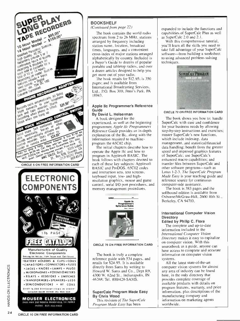
24
CIRCLE 5 ON FREE INFORMATION CARD
ELECTRONIC COMPONENTS)
'4 "N\ r+ ] i oit ( Mph_
R NICS
r Manufacturers of Quality 1 Electronic Components
Serving lee Nat ion from T nd Calif orals
BATTERY HOLDERS a CLIPS COILS CAPACITORS CONNECTORS FUSES
JACKS KNOBS LAMPS PLUGS
MICROPHONES POTENTIOMETERS RELAYS RESISTORS SWITCHES
TRANSFORMERS SPEAKERSLEDS SEMICONDUCTORS RF COILS
0001 l 000 Dltf!fNt ilOMS IN STOCK <r,005 eAiit0 00rf10t USA 5t M0 1] 00
MOUSER ELECTRONICS 2401 ttWY 287 NORTH f2ANSO'EIO. IX 76063
PHONE 817-483 4422
CIRCLE 10 ON FREE INFORMATION CARD
BOOKSHELF (Continued from page 22)
The book contains the world radio spectrum from 2 to 26 MHz, stations arranged by frequency including station name, location, broadcast times, languages, and a convenient cross -index of major stations arranged alphabetically by country. Included is a Buyer's Guide to dozens of popular portable and tabletop radios, and over a dozen articles designed to help you get more out of your radio.
The book retails for $12.95; is 350 pages; and is available from International Broadcasting Services, Ltd., P.O. Box 300, Penn's Park, PA 18943.
Apple Ilc Programmer's Reference Guide By David L. Heiserman
A book designed for the experienced, as well as the beginning programmer, Apple IIc Programmers Reference Guide provides an in -depth explanation of the IIc, along with the information required to machine - program the 65CO2 chip.
The initial chapters describe how to operate the Apple IIc and how to program in Applesoft BASIC. The book follows with chapters devoted to each of these key subjects: Applesoft BASIC and ProDOS, 65CO2 codes and instruction sets, text screens, keyboard input, low- and high - resolution graphics, mouse and game control, serial I/O port procedures, and memory management procedures.
Apple 110
Programmer's Retererxe Guide
CIRCLE 76 ON FREE INFORMATION CARD
The book is truly a complete reference guide with 534 pages, and retails for $24.95. It is available directly from Sams by writing to Howard W. Sams and Co., Dept R9, 4300 W. 62nd St., Indianapolis, IN 46268; Tel. 800 /428 -SAMS.
SuperCalc Program Made Easy By Chris Wood
This revision of The SuperCalc Program Made Easy has been
expanded to include the functions and capabilities of SuperCalc Plus as well as SuperCalc 2.0 and 2.1.
With this comprehensive tutorial, you'll learn all the skills you need to take full advantage of your SuperCalc software-from building a worksheet to using advanced problem -solving techniques.
CIRCLE 72 ON FREE INFORMATION CARD
The book shows you how to: handle SuperCalc with ease and confidence for your business needs by allowing step -by -step instructions and exercises; master SuperCalc's new functions, which include indexing, data management, and statistical /financial data handling; benefit from the greater speed and improved graphics features of SuperCalc; use SuperCalc's enhanced macro capabilities; and transfer files between SuperCalc and other software programs -such as
Lotus 1 -2 -3. The SuperCalc Program Made Easy is your teaching guide and reference source for continuous computer -side assistance.
The book is 383 pages and the softbound edition is available from Osborne /McGraw -Hill, 2600 10th St., Berkeley, CA 94710.
International Computer Vision Directory Edited by Philip C. Flora
The complete and up -to -date information included in the International Computer Vision Directory makes it easy to capitalize on computer vision. With this sourcebook as a guide, anyone can have access to complete and accurate information on computer vision systems.
All the latest state -of -the -art computer vision systems for almost any area of industry can be found here, in the only directory that provides complete coverage of available products with details on program features, warranty, and price information, plus descriptions of the manufacturing company and information on marketing agents worldwide.

CIRCLE 79 ON FREE INFORMATION CARD
Complete with a glossary of terns. the directory provides full -page specification -oriented listings. The sourcebook offers speedy access to the right system for any need with two indexes -one arranged by company name, the other by application. Information is included on such topics as computer vision systems, automated inspection systems, robot/vision systems, vision process control. cameras (vidicon and solid state). vision peripherals, and components pattern processors.
The book sells for $34.00, is 160 -
pages, and available from TAB Professional and Reference Books, P.O. Box 40. Blue Ridge Summit. PA
17214: tel. 717/794 -2191.
1 -2 -3 Tips, Tricks, and Traps By Dick Andersen
Trying to become a 1 -2 -3 hacker? Here's a hook on how to do it the easy
way. Users can learn new shortcuts. pitfalls to avoid, and problem -solving hints in / -2 -3 Tips, Tricks, and Traps. which targets Release 2's expanded worksheet; expanded memory capability; and new functions, database commands, and macro applications.
An essential desktop reference, this book is designed to be read not from cover to cover, but rather as a
compendium of individual problems with individual solutions.
CIRCLE 78 ON FRE E INFORMATION CARD
Regardless of how much a user may know about 1 -2 -3, this how -to book has many new ideas and techniques for you to try.
1-2 -3 Tips, Tricks, and Traps. costs $19.95, contains 418 pages, and is available in most bookstores and computer stores throughout North America. To order directly from Que Corp.; call 800/428 -5331 and ask for a
sales representative.
STRONGER MAGNET TO STUDY ELECTRONIC MATERIALS
A magnet has been built that provides substantially higher pulsed- magnetic fields than was possible before. Using newly developed technology, researchers now have a much better and less expensive tool for studying a variety of electronic materials -electronic and magnetic prop- erties of metals. semiconductors, super- conductors, and magnets. These magnet- ic fields interact very strongly with elec- trons and atoms, enabling researchers to learn a great deal about the basic proper- ties of materials.
The stronger field was produced by Si- mon Foner, chief scientist at the Mas- sachusetts Institute of Technology's Francis Bitter National Magnet Laborato- ry in Cambridge, Massachusetts. Foner, in collaboration with Supercon. Inc., a
small company in Shrewsbury, Mas- sachusetts, developed an ultra -strong cop- per wire containing niobium filaments for the magnet's winding, and achieved fields of 68.4 tesla, more than a million times the earth's magnetic field, for 5.6 thou- sandths of a second. A tesla is an interna- tional unit of magnetic flux density about 20,000 times the earth's magnetic field.
A wire made of a new material with High electric and thermal conductivity, and high mechanical strength. was needed to achieve such a high magnetic field because magnetic forces above 50 tesla destroy conventional copper -wound solenoids (coils of wire), even when rein- forced with hardened steel. The wire is
composed of millions of filaments of niobium metal, each less than a millionth of an inch in cross section. embedded in a
copper wire. Foner said his work suggests that ener-
gy- efficient systems of 75 -tesla strength or more. with pulse lengths nearly 100
times longer than those now attainable, can be built economically with this new wire- making technology.
The copper- niobium wire was de- veloped by researchers trying to find an
easily pliable superconductor which could be used in high -field, steady -state magnets, possibly for magnetic fusion confinement or for large accelerators such
as the proposed Superconducting Super - collider. Niobium, a metallic chemical el- ement, is superconducting, with no
resistance at low temperatures.
4 MORROW 5 t CP /M ENGINE
e
m , 1 76-air atrar'e 4 Cver 1 5,000 of these single
board computers Installed. 4 Free copy of the 'MORROW
OWNERS REVIEW'. The national magazine devoted just to the MORROW computer. ;úGGfie, Ia,t 4 We have over 1 500 in stock 4 mhz Z80A CPU, b4K RAM
: 6/32K ROM (32K rom rev 2 supplied) I. 2 RS232 serial ports (300 -+
' 9 2k baud with db25 con- nectors installed)
a Centronics printer port (cable 58) 4 ?ower requirements-
- 1 2vdc - 1 2vdc +5vdc 4 Floppy disk controller up to 4 Srives SSDD standard Rom for )SDD 48tpi or 9btpi S 12 extra including assembled bios CP /M bios, Newword and Bazic included. Schematic, bios.asm, maint -manual and users guide .ncluded Copy program to read /write non morrow formats such as Kaypro, Osborne. Xerox.& IBM Jptional rs232 terminal pcb, rTL monitor pcb, and display tube S59(with purchase of cpu , a 3ó savings from separate price)
Call our bbs at 41 5 -261 -451 3 ' Cell fe COI Of 15 dal trial meat. Tax & frig, At extre.Send check or odd 1.90 for COD. Priciq roso, chase.5tere Price Mil dlrfer.While 3/11.1.1113 Ital. Ne P03, term, or relit card,
ilicon alley urplus 415-261-4506
440 , OAKPORT OAKLAND CA, 94601 /
OPEN 10em -6pm CLOSED 5UN A,MON
CIRCLE 12 ON FREE INFORMATION CARD
Put Your Electronic Skills to Work in ROBOTICS NOW!
ROBOT VEHICLE 4ie, PILOTITECH Financial Aid Placement Assistance
HIGH PAY HIGH TECH
EXCITING CAREERS
Electronic, Hydraulic & Robotic Skills Taught.
Call or Write for FREE BROCHURE TODAY.
Ask About Our Correspondence Course
(713)690 -0405 UNDERWATER VEHICLE TRAINING CENTER
10046 Chickasaw, Houston, TX 77041
CIRCLE 18 ON FREE INFORMATION CARD
25

26
By Herb Friedman
I7 ° ON COMPUTERS
Communications by modem sometimes needs witchraft!
L,WHILE YOU CAN LITERALLY SPEND A
lifetime using personal computers with- out ever having to send or receive data via modem, the plain fact of the matter is that the world is against you. Each day, some heretofore simple way of doing things is made more complex because the system demands it be done by modem.
To that end, the marketplace offers more modems and communications soft- ware than anything else, excepting word processors. Unfortunately. what one buys and how much one spends is often deter- mined more by the prejudices of others than by actual need, because users often haven't the knowledge to understand what the various kinds of modems and software will do for them.
That comes about because there are really two basic forms of modem commu- nications, each having several subgroups. The most popular form of modernized communications -because it is used in elementary schools and virtually all pub- lic databases -is the so- called "ASCII" text. As you might guess, it is used pri- marily when the data consists of text, or recognizable characters. It's prone to both natural and man -made interference on the communications circuit; be it wire, radio, or satellite.
The interference can manifest itself by turning the entire message (transmission) into indecipherable hash (garbage), or by occasional character dropout or destruc- tion; i.e., the transmitted letter "R" might be received as a "Y," or a "7," or like something that came from outer space. Generally, the interference is on a random -character basis, which allows the receiving end to easily figure out what was originally transmitted.
On the other hand, less popular with the average computer hobbyist -but far more important -is something known as protocol communication, whose claim to fame is that it is extremely accurate. Both ends of the circuit work together through special encoding called a protocol to en- sure that the data exchange is error -free. If something interferes with -actually changes -the transmitted data. the re- ceiving computer requests repeat trans- missions until both ends are certain that the exchange has been done with 100%
accuracy. In actual fact, errors can creep in when several million bits of data are involved; however, some communication software is more efficient than others at providing error detection, and it might be months before an error creeps in.
Databases are Text Virtually all commercial public -access
databases respond to ASCII text, meaning they receive and transmit characters repre- sented by decimal values known as the American Standard Code for Information Interchange (from whence the acronym ASCII is derived). For example, the "A" is represented by the decimal value 65. When you press the letter "A" on an AS- CII keyboard, the output is really a data stream representing the number 65. It's a 65 that arrives at the receiving computer, which the communications software rec- ognizes as the letter "A." Similarly, the carriage return produces the decimal val- ue 13, which all ASCII equipment recog- nizes as a carriage return.
Protocol data exchange works some- what differently. Essentially, the software transmits a block of binary data, say 256K. The originating software does a mathematical analysis of the individual bit or byte values and sends the total value called a CRC (Cyclic Redundancy Check) -also known as the test value or checksum -either before or after the data block is sent. For all practical purposes. they are all the same thing.
The receiving software does the same analysis on what it receives and compares the calculated CRC value with the re- ceived value. If there is any variation whatsoever, no matter how insignificant, the receiving computer asks the originat- ing location to repeat and repeat until ev- erything matches.
On a noisy communications circuit, the transmission might be repeated once. twice. perhaps ten times. Most software have a built in limit so it doesn't go on repeating forever on a noisy circuit: After some ten or so attempts most protocol software will terminate the data exchange. with a screen display to that effect.
No Standard the problem with protocol exchange is
that there is no official standard, and dif- ferent systems are mutually exclusive be- cause they use different means to determine the CRC and checksum values. Two of the most popular protocols are XMODEM (because it's free), and CROSSTALK (because it's extremely accurate, being primarily intended for protocol data exchange). A more recent newcomer, particularly useful for those who must communicate with mainframe computers, is KERMIT.
But there's lots of money to be made in communications software, and it's not going to be made by selling a competitor's system, so many attempts have been made to market proprietary hardware and soft- ware; proprietary meaning that the hard- ware and software design isn't compatible with anything else. That's OK if you're using your computer to communicate within your own network, such as home - to- office; but it often precludes you from communication with others who use more popular software and hardware -and that's where the problem comes in.
This tiny battery- operated modem, which is intended for portable computers. isn't much larger than a
few fingers. yet it packs the full complement of Hayes commands. It ran from every standard and conventional software package we tried.
When the oddball hardware and soft- ware fails to make a dent in the market- place. it is often sold to a liquidator, who resells it to the public at large fora fraction of its original price. The stuff might be terrific, perhaps gold -plated unto itself, but it's non -standard. If the buy of the century hardware does not respond to the Hayes commands and it's software, the protocol might be unusable with the stan- dard biggies: XMODEM, CROSSTALK,

Now electronics technicians can get into VCR Servicing quickly and easily
Learn professional VCR servicing at home or in your shop
with exclusive videotaped demonstrations
Today. there are more than 10 million VCRs in use, with people standing in line to have them serviced. You can bring this profitable business into your shop with NRI professional training in VCR servicing. This top -level training supports the industry's claim that the best technicians today are those who service VCRs.
Integrated Three -Way Self -Teaching Program In one integrated program, NRI
gives you a study guide, 9 instructional units, 2 hours of video training tapes accompanied by a 32 -page workbook that pulls it all together. At home or in your shop, you'll cover all the basic concepts of video recording. mechani- cal and electronic systems analyses, and the latest troubleshooting tech- niques. Your workbook and instruction- al units also contain an abundance of diagrams, data, and supplementary material that makes them valuable addi- tions to your servicing library.
The "How -To" Videotape Your NRI Action Videocassette uses
every modem communications tech- nique to make learning fast and easy. You'll enjoy expert lectures and see animation and video graphics that make every point crystal -clear. You'll follow the camera eye into the heart of the VCR as step -by -step servicing tech- niques are shown. Both electronic and mechanical troubleshooting are covered
. including everything from com- plete replacement and adjustment of the recording heads to diagnosing micro- processor control faults.
Plus Training On All The New Video Systems
Although your course concentrates on VCRs covering Beta, VHS, and -1/4"
U -Matic commercial VCRs, NRI also brings you up to speed in other key areas. You'll get training in capacitance and optical video disc players, projec- tion TV, and video cameras. All are in- cluded to make you the complete video technician. There's even an optional final examination for NRI's VCR Pro- fessional Certificate.
Covers Beta and VHS systems with actual
instruction on videotape.
The Best Professional Training
This exclusive self -study course has been developed by the professionals at NRI. NRI has trained more television technicians than any other electronics school! In fact, NRI has consistently led the way in developing troubleshoot- ing techniques for servicing virtually every piece of home entertainment equipment as it appears in the market- place.
Satisfaction Guaranteed ...15 -Day No -Risk
Examination Send today for the new NRI Self -
Study Course in VCR Servicing for
SI Get nie started in profitable VCR servicing. Rush me my
NRI self -study course in VCR Servicing for Professionals. I understand I may return it for a full refund within 15 days if not completely satisfied.
PLEASE SPECIFY TAPE FORMAT DESIRED VHS
Name (please print)
Company
Street
City/State/Zip
Enclosed is my check money order for S179.95 'D.C. residents add 6(i tax) Make check payable to NRI
Charge to VISA MasterCard
Professionals. Examine it for 15 full days, look over the lessons, sample the videotape. If you're not fully satisfied that this is the kind of training you and your people need to get into the profit- able VCR servicing business, return it for a prompt and full refund, including postage. Act now, and start adding new business to your business.
Special Introductory Offer This complete VCR training course
with two hour videotape is being offered for a limited time only, on orders received from this ad, at our low introductory price of $179.95. Save $20 by acting now! NRI Training For Professionals McGraw -Hill Continuing Education Center
3939 Wisconsin Avenue Washintl, DC 20016
BETA
R\RI Training For Professionals
McGraw -Hill Continuing
Education Center
3939 Wisconsin Avenue I Washington, DC 20016
Interbank Number
Card Number - Expiration Date
Signature
required for credit card sales) 2635 -057
co co v
27

28
You Can Be
One Of The
20,000 Technicians
Certified BY ISCET
ISCET CERTIFIED
The International Society Of Certified Electronics Technicians offers permanent certification by administering the CET exam with the FCC recognized communi- cations option for $20. A second exam on FCC regulations for a $10 fee is re- quired for a Radiotelephone license. Upon passing, technicians receive both a
permanent Radiotelephone Operator Cer- tificate and a CET Certificate issued by ISCET.
ISCET Offers License Renewal
ISCET has developed a program for regis- tration of those who currently hold a
valid Radiotelephone Operator License. By sending a completed application, a
photocopy of your FCC License, and $10 your license will be renewed with the assurance of a recognized national tech- nicians association behind it.
For More Information Contact:
ISCET 2708 W. Berry, Ft. Worth, TX 76109. (817) 921 - 9101
CABLE TELEVISION CONVERTER
CABLE TELEVISION CONVERT- ER, descrambler and wireless remote control video equipment accessories. Catalog free.
CABLE -DISTRIBUTORS UNLIMITED
116 Main Road Washington, AR 71862
CIRCLE 22 ON FREE INFORMATION CARD
CROSSTALK - XVi Status Screen - , On line
NAme RADIO ELECTRONICS BBS Waded E: REI2B8S.XTK NUmber 2932283 CApture Off
SPeed DAta POrt
Communications parameters - 1200 PArity None D1lplex Full 8 STop 1 EMulate None 1 Mode Call
I ATten Esc. SWitch Home
Key settings
DRive E: DPrefix ATDP PRinter Off PMode 2 (DOS) EPath Vldeo EGA/Mono
Command ETX (-C)1 BReak End
Filter settings DEbug Off LFauto TAbex Off BLankex INfilter Off OUtfilt.r
Off Off On - SEnd control settings
CWait None LWait None
Miscellaneous parameters
ACcept Everything DSuffix UConly Off BKsize 1
RDials 10 FLow S / "8 LBreek 200
PWord APrefix ATS0 =1; ANswback Off DNames 200 TUrnernd Enter HAndshak Off
Cnmmnnd^
Fig. 1 -This printout of a CROSSTALK screen display shows that just about every operating parameter can be user -programmed to match the modem and its operating conditions. Not all software has this much flexibility. so if you're saving big bucks on the hardware make certain the modem will run off your software.
and KERMIT.
The AT commands -fu explain. B) default, the D.C. Hayes
AT commands -used by the Hayes Smartmodems -are the standard for all popular modems. All Hayes commands to the modem are prefaced by the letters "AT" (meaning, attention; commands come next). To instruct a Hayes- compati- ble modem to dial using touch -tone fre- quencies, the user sends the Hayes command ATDT. To instruct the modem to answer on the fifth ring the user would enter the Hayes command ATS5 (AT. at- tention; S, number of rings to answer, and 5. fifth ring). To instruct the modem to hang up the user keys in ATH.
There's a whole slew of AT commands, and most communications software is de- signed to use the Hayes commands. Also, most conventional modems will respond to the AT commands; even the battery- powered Wordlink 1200 modem (see pho- to), which is specifically designed for use with portable computers -such as mar- keted by Radio Shack and NEC -re- sponds to the Hayes commands.
The reason, of course, is that while the software built into the portable computers doesn't necessarily have to use the Hayes commands, if you intend using the hard- ware with other computers and software, it might not be possible if the modem didn't respond to the same commands al- most everyone else uses. Also, any soft- ware written for general -purpose commu- nications will most likely accommodate the Hayes commands either exclusively. or in conjunction with proprietary com- mands.
Regardless of how good a colossal buy in communications hardware and soft- ware might appear at first glance, keep in mind the kind of limitations you face.
While just about all software will commu- nicate in ASCII text, proprietary pro- tocols will preclude you from error -free data exchange with computers using the more common and popular software.
However, some of the most high - powered communications software can accommodate virtually any kind of modem commands. For example, as you can see from Fig. I, which is a screen - print from CROSSTALK communica- tions software, virtually any command is under automatic, if not manual, control. As an example. the dial prefix, which is set for the Hayes ATDP (dial pulses), can be set for anything needed; if your par- ticular modem doesn't use the Hayes commands, you simply enter whatever your modem requires. Similarly, for the Hayes answer pick -up (discussed earlier), if your modem needs different commands you simply key in what's needed. It's the same way with just about everything else.
Of course, the flexibility of CROSSTALK isn't common to all soft- ware, so if you're looking for super -bar- gains in modem hardware, make certain it will run from your software with all the bells and whistles. Remember, it doesn't make much sense to save $100 on the hardware if it takes $150 worth of software to get it up and running.

Your guide to every- thing that's new in elec- tronics, computers and technical education. Over 400 items. Discover fascinating kits to build, enjoy and learn with, as well as assembled high tech products for home, business and hobby.
r Heath Company Dept. 107 -534 Benton Harbor, Michigan 49022
MAIL COUPON TODAY and receive the latest issue of theHeathkit Catalog free of charge
Name
Address
City State
CL- 783BR3 Zip
A subsidiary cf Zenith Electronics Corporation L CIRCLE 15 ON FREE INFORMATION CARD

PARTS LIST FOR THE STEREO ADAPTER
BP1 -BP4 -Red binding post BPS -Black binding post (All fixed resistors are 1/4-watt, 10 °r° units.) R1- R4- 100,000 -ohm R5-R16 -10000 -ohm R17, R18 -10000 -ohm. "2 -watt, linear -taper
potentiometer R19, R20 -5000 -ohm, '-`2-watt, linear -taper
potentiometer U1, U2 -741 operational -amplifier integrated circuits Printed circuit board (Radio Shack 276 -170 or equivalent), #22 insulated hookup wire, cabinet (Radio Shack 270 -627 or equivalent), grounding lug for the cover, 4 knobs for R17 -R20, powercord growercord. soldtc.
H/ +15V f 1A/Ar -
H
POSN
15V +WV 111
H IN O-- BP3
15V
H
GAIN
R15
+15V
DIN O BP4
D
POSN
R16
R19 R14 M R1
R17
R20
D R18
GAIN
R2 -4/4A- W R8
R13 M R3
VA,
R4
R5
:1A
u
R
R11
+15V
7 \ 6
4
R9
VN
U
15V
+15V
7
4
O ROUT
BPI
15V
O L OUT BP2
BGND 5
Fig. 1 -The power supply for the stereo adapter is not shown. The Circuit can make use of a standard dual supply.
The waveforms for the horizontal (H) and depth (D) inputs are added in UI, and so produce deflection in the same direction in the right image.
DC "signals" from position (POSN) potentiometers are likewise added in UI and subtracted in U2. Thus, the H POSN control causes the left and right images to move in the same direction; whereas the D POSN control causes them to move oppositely to each other, thus, producing the effect of an "in -out" motion when viewed stereoscopically. In order for this method of CRT beam positioning to work, the os- cilloscope's deflection -channel amplifiers must be DC cou- pled all the way from the input jacks to the CRT deflection plates. Nearly all modern oscilloscopes have that feature.
Notice that the amplifiers are DC coupled, so waveforms containing large DC components must not be used as inputs without the use of series DC- blocking capacitors. In any
Fig. 2 -All dimensions for the adapter's face plate are in inches. Note that the binding -post holes are out of round. That is to accom modate the posts peculiar shape. The holes can be created by drilling with a'+ -in. bit and a round file.
34
event, inputs should not exceed + 15 volts, as larger voltages could damage the op -amps. Frequencies from DC to about 100 kHz are suitable as inputs.
Adapter Construction All parts were mounted in a Radio Shack #270 -627 case
on a Protoboard, although another case certainly would be suitable. A panel drilling pattern is shown in Fig. 2.
Once you have obtained the parts listed in the Parts List, construction can begin. Start by inserting and soldering corn - ponent leads in the PC board, according to the pattern shown in Fig. 3. Using IC sockets for the op -amps (UI and U2) is optional. The author did not use any.
Take your time because mistakes are easier to make than to find and correct later. Recheck your work frequently along the way. Be sure to add wire jumpers where indicated, just as if they were another component. When the PC board is wired and soldered, give it a final inspection. Then remove solder flux with an old toothbrush dipped in alcohol; but scrub gently! Now set the PC board aside in a safe place.
Redraw the front -panel drilling pattern full size on a piece of paper, using Fig. 2 as a guide, then cut it out along the panel outline. Check the locations of the B -size holes to be sure they are correct for keying the particular potentiometers you plan to use.
Tape the front -panel pattern to the lnmt panel anti ¡lunch
+-1
/4
6
2
t--2 1/2
1 3/8-+1 +-7-11/4-il
+-1-3/4-81 + 1
5/8
--. It--1 1 /2 -i--
8--4E1) .8- A
-w
+/, f
1 4 A 5/16 DIA B 1'8 DIA.
C14?IA AND It

The Stereo Adapter Set -up and Test Procedure
When construction has been com- pleted. yot. are ready to set up and check out your stereo -oscilloscope.
Position the oscilloscope on -end on the table top where it will be used. Power it up and set the controls for dual -trace use. Obtain two sweep baselines: Position them so they straddle the CRT's horizor-al cen- terline equally as shown in Photo A.
Set the scope gain controls for the two channels to the same sensitivity (about 1 V cm) and do not change them.
Power -up the stereo adapter and check the operation of the two posi- tion (POSN) controls. Rotation of the H POSN control should cause the two traces to move in the same direc-
ton. (Side -to -side as viewed from the side of the scope.) Rotation of the D POSN control should cause them to move oppositely to each other.
If these or any subsequent tests have negative results, remove power from the stereo adapter and trou- bleshoot it- starting with a detai'ed visual inspection (i e., whenever the
oscilloscope is used in the stereo mode).
For the next test inject a sinewave at the H IN binding post and check to see that displays of identical sine- waves can be obtained on the two traces of the sc.x e. (Don't forget to
connect your sirewave generator ground to the system ground!) Adjust
the scope and stereo adapter con- trols to obtain patterns as shown in
Photo B. The displayed amplitudes of the sinewaves should be equal and controllable by the H GAIN potenti- ometer.
Now inject the same sinewave into the D IN binding post instead. Re- duced- amplitude sinewaves should appear on the two scope traces. and they should be 180 degrees out of phase with each other. Their ampl -- tudes should be equal and controled by the D GAIN potentiometer (see Photo C).
When the above tests have been satisfactorily completed you are ready to begin viewing stereo images using the stereo viewer.
the centers of the holes to be drilled. Remove the pattern and drill the holes. Oblong holes for the binding posts should be
drilled undersize, then filed to their final shape to properly accommodate the binding posts.
Install the panel components, and wire them first to one another, and then to the board according to Fig. 3.
Carefully solder all connections and inspect your work,
qBP1 BP2
,. . F _ , 1`
. J1 .-. 1 s1 a r
s
. i t
a a a i .46-4 e i
}
: e t . 1 . .
, to
i10
10 R6 R9
1
looking for possible errors. (You know the routine!) Gently fold the wires to the PC board so that the PC board
is lying parallel to the front panel in such a way that the
assembly will fit into the case. Label the front panel following Fig. 8, using your favorite method. (The author simply typed on sticky -backed paper, covered this with transparent tape to prevent smudging, cut out the legends, and stuck them in
- .._----+-----o--r+-- ..
R16
I
a FL
R12
... R2 - . -
,
118 - 4;3- - '- .--. -1111--- '_.
J
. -J- -J- R4-1.1_
. t
*120 Bpi _ BP4
o- RR1111~ R18
15V
iU 45
ß 5 z 9 ! 0 S ;i
t a . . a t E 0 -.
t ß : e 0 t
. e e e a a.
. . . . r a a a t
ß _ a t a e t
t a ß. t t a t a a : r, . i+ a< t t t a
a a . , . r a x a
R19 _/
Fig. 3 --he circuit board has plenty of room left over for the placement of add -on parts such as input and output buffer staces. or perhaps a simple function generator.
>
35

36
R20 R17
BP2 . BP1 R19 ¡
R18
BP3
BP5
RP4
The panel layout shown here is not a must for proper func- tioning of the circuit however, its symmetry will provide ease of use. The user can become familiar with the controls and binding post's quickly in an intuitive fashion.
place on the panel. That method is quick, neat, and the results are attractive.
Put the assembly in its case and fasten the front panel to the case using the four screws provided with the case. The stereo adapter is now complete. Set it aside -again in a safe place!
Stereo Viewer Before beginning construction on the stereo viewer, you
must lay out a diagram similar to that shown in Fig. 4. The dimensions in the diagram depend on your components. Dimension f is the focal length of the two lenses (both lenses must be identical). One method of finding the focal length, f, of a simple positive (converging) lens is to use a near- source. The lens is used to focus the image of a ceiling light (the near - source) onto a table top, then the focal length can be deter- mined by measuring of the light -to -lens distance, p, and the lens -to -table distance, q. Then use the formula:
f = pq /(p +q)
The units of p, q, and f are unimportant. but must be the same. If they are inches, then f will also be inches.
A second method is to use a far -source. If the lens is used to focus an image of the sun (the far -source) onto a surface, then the distance from the lens to the surface is f.
Dimension S is one -half the useful screen height. but not to exceed 2 -1/2 inches. (This becomes one -half the useful screen width in this application.) The purpose of the diagram is to determine dimension A. Once dimension A has been determined, the patterns in Fig. 5 can be laid out.
CRT SCREEN
LENS PLANE
a- 1.50 RIGHT EYEPOINT
2.50 EYE SPACING
E
LEFT EYEPOINT
Fig. 4-If you are not going to buy the standard lenses mentioned in the text you will have to first find the lenses focal length (as per the text), and then use this drawing to determine the viewers A and F dimensions.
Viewer Construction Lay out two patterns A and one pattern B on heavy poster -
board according to Fig. 5. The diameters of the two holes in each pattern depend on the lens' diameter. Diameter D2 should be just slightly larger than the lens diameter and Dl should be smaller than the lens diameter, so that when a
sandwich is made from the three patterns with the lenses in place, the lenses will be retained. Cut out the three patterns from the posterboard.
Now lay out the shroud full scale. Half the shroud is shown in Fig. 6; the other half is its mirror image. Transfer this pattern to a piece of heavy acetate or similar stock. (Suitable material can be obtained from a plastic two -liter soft -drink container.) If the material you have used is transparent, it will have to be painted (later) to make it opaque.
Assemble the lens holder and lenses from the three patterns you cut from posterboard following Fig. 7. You may wish to tape them together as the author did, so that the lenses could be salvaged later without destroying the lens holder. If you've no future designs on them, then glue them, being careful not to contaminate the lenses.
Cut two pieces of quarter -inch hard balsa wood or similar material into crescent -shaped pieces as shown in Fig. 7. Dimension B depends on your oscilloscope, and should be such that the two legs (when they are attached) will straddle the CRT bezel from top to bottom. Glue the two pieces of balsa wood in place.
Next, cut two legs of posterboard to support the stereo viewer above the CRT screen at the proper distance; the "proper distance" being such that the distance from the CRT phosphor screen to the lenses is equal to the lens focal length, f. The other dimension of the legs should be approximately 2- %a inches. Glue these two legs to the stereo viewer as shown.
After all the glued joints are dry and firm, wrap the shroud around the lens holder and attach to the two balsa wood pieces using four small wood screws. Drill holes for the screws so as not to split the balsa wood.
A final touch is to spray the stereo viewer with flat black paint. Be sure to adequately protect both sides of the two lenses during this operation. Finally, a strip of felt can be glued around the exposed edge of the shroud if desired.
Notice the special grounding lug connecting the ground binding post (BP5) to the panel faceplate. Although it is not an absolute necessity, it is wise to install it.

B
5.50
Fig. 5-You will have to experiment with the size of the nose bridge. Be sure to leave enough clearance for the placement of felt material for comfort.
Taping the viewer together may be preferred over gluing it if you will use the lenses for something else in the future.
This completes the stereo viewer and you are ready to connect the system together as in Fig. 8 and follow the procedure outlined in the set -up section.
Viewing the Images Position the stereo viewer atop the oscilloscope in the
position shown in the photos. Start with no inputs to the stereo adapter (or turn its two GAIN controls all the way counter -clockwise). Two baseline traces should be present as in the setup procedure.
View the traces by placing your head against the stereo
1.25
j
i
1 1.00
2 75
Fig. 6 -The shroud material should be flexible for easy shaping (a plastic soda bottle is recommended as long as the sharp edges are covered with felt or a similar material. Note that this drawing is not scaled or proportional.
-
i
1/4 -INCH BALSA WOOD
SEPTUM
POSTER -BOARD (SEE TEXT).-
B
- 1
lT LENS HOLDER PATTERN
r I A
LENS HOLDER PATTERN
Fig. 7 -When making the poster -board legs, be sure to subtract the thickness of the balsa wood from the focal length to arrive at L. That will optimize the accuracy of the lens placement for a crisp focus on the CRT.
viewer. Rock the H POSN and D POSN controls slightly until fusion occurs. Fusion means the two images are seen as one; with one image being viewed by the right eye only, and the other by the left eye only. If obtaining fusion is difficult, relax your vision by imagining you are looking at a far -away mountain top. Blink normally, do not stare. and give yourself time. When fusion occurs. you will see the image "lock in" and remain rock steady. (With practice you will find it easier and easier to obtain fusion.)
As a further check to see if fusion has occurred, slowly rock the D POSN control through a very small arc. The traces (which you now see as a single, fused trace) should appear to move toward and away from you.
Experiment with the two POSN controls to find the set- tings which produce fusion best. Those will be your POSN- CO
37
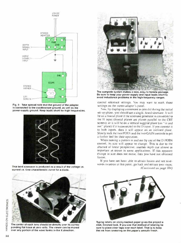
38
DEPTH SIGNAL INPUT
15VDC POWER
STEREO ACAPTER
HORIZ SIGNAL INPUT
STEREO VIEWER
CRT SCREEN
Fig. 8 -Take special note that the ground of he adapter is connected to the oscilloscope ground, as well as the power -supply ground. Keep leads short for high frequencies.
This bent sinewave is produced as a result of the voltage vs. current vs. time characteristic curve for a diode.
The center of each lens should be directly over its corres- ponding flat trace at zero volts. The viewer can be moved over any portion of the wave forms in the X direction.
The complete system makes a nice, easy to handle package. Be sure to keep your power -supply and input leads short to avoid inductance problems in the high- frequency ranges.
control reference settings. You may want to mark those settings on the stereo- adapter's panel.
Now, by displaying a sinewave as you did during the initial set -up phase, you should see a single, fused sinewave. It will be on a frontal plane if the sinewave generator is connected to the H input (frontal planes are planes parallel to the CRT screen); or it will be on a vertical saggital plane (an "in and out" plane) if it is connected to the D input. If you connect it to both inputs, then it will appear on an inclined plane. Slowly rock the two POSN and the two GAIN controls to get a further feel for their operation.
When moving a pattern in and out by use of the D POSN control, its size will appear to change. This is due to the absence of linear perspective, another depth cue almost as important as stereo in some applications. If this apparent change in size does not occur, then you have not obtained fusion.
If you have not been able to obtain fusion and see sine - waves in stereo at this point, go back and retrace your steps;
(Continued on page 104)
Typing labels on sticky- backed paper gives the project a neat, finished look. If you use that method of labeling be sure to place clear tape over each label. That is to keep the ink from smearing on the paper's smooth finish.

Here are your trie
FactCards! Introducing Hands -On-
Electronics FactCards. Each issue, Hands -On-
Electronics will present 3 new FactCards, each deal- ing with one of a variety of electronics topics. Some will deal with electronics basics, some will deal with discrete components, some will deal with IC's, and some will deal with circuits and applications.
All will contain the type of information electronics hob- byists need, but sometimes must search to find. With FactCards, you can find that information in a hurry.
Clip your cards, save them, and start building your FactCards library today!
a=n** nC°s°
34 Ere"^ FactCard Transistor Package Outlines
(All Dimensions In Inches)
--11 0.240 1...._ I 0:110
-1- 1.8 IN
+ti
TO-1
4-0.650 01A.
0.330
.360 MIN.
TO-8
4- 0.370
0.260
0.50 }MIN
TO-39 T052
05
0.230
0.210
0.500
TO-72
-{ 0.42 14--
0.625
0.500 MIN
TO-220
.195 --.1
210
.055
T0-98M
0.62
t 0.57 0.13
0.5 MIN
T0-218
4022: Divide -By -N BCD Counter 35 l on FactCard 4026: Divide -By -N Binary- Counter
116 115 114 113 112 111 110 19
11 12 13 14 15 16 17 18
CLOCK INHIBIT ENABLE RESET ACT1Oñ
0 0 0 0 No cou Pos Trans. 0 0 0 Count 1,
X 1 0 0 No cou 1 Neg. Trans. 0 0 Count 1
X X 1 0 Preset X X X 1 Reset
Features wide supply voltage range 3.0V to 18V High noise immunity 0.45 VI:to (typ.) Low power TTL fan out of 2 driving 74L compatibility or 1 driving 74LS Quiescent current = 5nA/package (typ.) (a Voo = 5.0V Internally synchronous for high internal and external speed Logic clocked design -incremented on positive transi- tion of Clock or negative transition of Clock Inhibit Medium speed 7.7 MHz (typ.) (a Voo = 10V Asynchronous Preset Enable
Absolute Maximum Ratings
Voo Supply Voltage -0.5 to +18V VIN Input Voltage - 0.5 to Vou +0.5V Ts Storage Temperature Range -65°C to +150°C Pp Package Dissipation 500 mW TL Lead Temperature (Soldering, 10 seconds) 260 °C
Recommended Operating Conditions
Vco Supply Voltage VIN Input Voltage TA Operating Temperature Range
3 to 15V 0toVppV
- 55°C to +125°C - 40°C to +85°C
36 &sun FactCard 4027: Dual J -K Master/ Slave Flip -Flop
116 L_ 114 113 11 110 19 tlriiÍi® F/F1 ¢
T1 12 13 14 I5 it 11 I8
INPUTS OUTPU
J K S R O O O
C Trans. I-. . Trans. ; Trans. i., . Trans.
. Trans.
.
1
x o x x x
,.x ..
x o x 1
x x X
o 0 o 0 o 1
o
0 0 0 1
0 0 0 1
o x ox t so
1 0 1 o 0 1
o 1
(No change) 1 0
1
Features Wide supply voltage range High noise immunity Low power TTL compatibility
Medium speed operation
Absolute Maximum Ratings
VD° Supply Voltage VIN Input Voltage Ts Storage Temperature Range Po Package Dissipation TL Lead Temperature (Soldering, 10 seconds)
3.0V to 15V 0.45Voo (typ.)
fan out of 2 driving 74L or 1 driving 74LS
50nW (typa 12 MHz (typ.)
with 10V supply
-0.5to +18V -0.5 to Vco +0.5V
- 65°C to +150°C 500 mW
260°C
Recommended Operating Conditions
VIN VA., Input TA Operating emperature Range
3 to 15V OtoV V
- 55°C to +125T - 40°C to +85°C
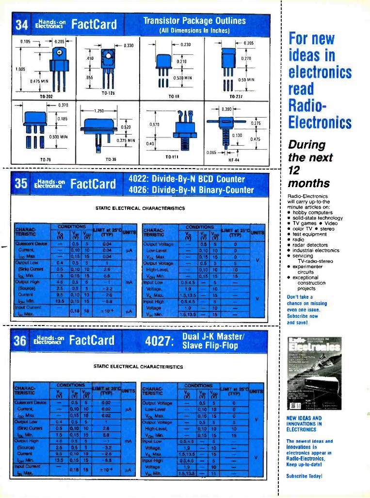
34 Etvg,K:" FactCard Transistor Package Outlines (All Dimensions In Inches)
0.105 0.285 H
1.005
TO-202
0.370
-11
450
655
y-- T0-126
f~ 0.330 0.230
0.500 MIN III_ TO-18
1.- 0 205
0 270
0.50 MIN
00_1_ TO 237
0.185
[11 m
OS00MIN
TO-7B
1.250 -- O.iZO
0.375 MIN
T0 36
- +{ 0.390
To-111
-T- 0 275
0.415
35;K°" FactCard 4022: Divide -By -N BCD Counter 4026: Divide -By -N Binary- Counter
STATIC ELECTRICAL CHARACTERISTICS
TERIST1C A UNITS (,17
on on VRp
15 (TYP)
Qiesoent Device 0.5 0.04 Current, - 0,10 10 0.04 µA 60 Max - 0,15 15 0.04
Output Low 0.4 0.5 5 1
(Sink) Canent 0.5 0,10 10 2.6 la Min. 1.5 0,15 15 6.8
Output High 4.6 0 5 5 - 1 mA
(Source) 2.5 0 5 5 - 3.2 Current 9.5 0,10 10 -2.6 10 Min. 13.5 0,15 15 -6.8
Input Current - I,N Max. 0,18 18 - 10-5
_ Fif1
TERISTIC V (Rp X55)
tIMIT at 25 °C (TYP) UNITS V (,17 V (,+
Output Voltage -11 0.5 0
Low -Level - 0,10 10 0
Va Max. - 0,15 15 0
Output Voltage - 0 5 5 5
High -Level, - 0,10 10 10
Vo Min. - 0,15 15 15
Input Low 0.5,4.5 - 5 - Voltage, 1,9 - 10 - VI, Max. 1.5,13.5 - 15 -
Input High 0.5,4.5 - 5 - V
Voltage 1,9 - 10 - Vw.Min. . -..,15.13.5 -,..... >. ., --
36 l,IQCLIbf;Kf Fa ct C a rd w, Dual J -K Master/ 4027: Slave Flip -Flop
STATIC ELECTRICAL CHARACTERISTICS
CHARAC- TERISTIC
LIMIT at 25 °C (Typ) UNITS (çl V,, Vg
1557 Q/eecent Device 0,5 0.02
Current, - 0,10 10 0.02 PA IOO Max - 0,15 15 0.02
Output Low 0.4 0,5 5 1
(Sink) Current 0.5 0,10 10 2.6
Iqt, Min. 1.5 0,15 15 6.8 Output High 4.6 0,5 5 - 1 mA
(Source) 2.5 0,5 5 -3.2 Current 9.5 0,10 10 -2.6 1O4 Mln. 13.5 0,15 15 -8.8
Input Current - 0,18 18 It 10-6 µA Iw Max.
----":3 CHARAC- TERISTIC
MON iiiillifflIMPROPP-- ,pp
LIMIT t 25 (TYP) UNITS (,Q (43
Output Voltage - 0,5 5 0
Low -Level - 0,10 10 0
VO1 Max. - 0,15 15 0
Output Voltage - 0,5 5 5
High -Level, - 0,10 10 10
VON Min. - 0,15 15 15
Input Low 0.5,4.5 - 5 - Voltage, 1,9 - 10 - VII. Max. 1.5,13.5 - 15 -
Input High 0.5,4.5 - 5 - Voltage 1,9 - 10 - ViM Min. 1.5,13.5 - 15 -
For new ideas in
electronics read Radio- Electronics
During the next 12 months Radio -Electronics will carry up -to -the minute articles on:
hobby computers solid -state technology TV games Video color TV stereo test equipment radio radar detectors industrial electronics servicing
TV- radio -stereo experimenter
circuits exceptional
construction projects
Don't take a
chance on missing even one issue. Subscribe now
and save!
NEW IDEAS AND INNOVATIONS IN
ELECTRONICS
The newest ideas and
innovations in electronics appear in Radio -Electronics, Keep up -to -date!
Subscribe Today!

WITH THE CRIME RATE GOING OL I OF CONTROL. '
curity alarms- running the gamut from simply buzzers for use on doors or windows to expensiNc
whole -house systems that automatically dial a subscriber service -are a necessity today. And the cost of an alarm system that includes a few bells and whistles can be astro- nomical. But if you're among those who take pleasure in doing things for yourself, read on and see how you can build and install this home -brew system and pocket the savings.
This low -cost, battery- operated security alarm features un- usually low standby power consumption of a few microwatts. The circuit drives either a piezo buzzer or operates in con- junction with a smoke alarm equipped with a normally -open electrical test button. The tripped alarm sounds for about eight minutes and may be altered for continuous alarm. And get this: the security alarm includes door exit and entrance time delays, a feature found only on better -grade systems.
Circuit Operation Figure I shows the circuit for use with a smoke alarm.
Figure 2 shows the modifications to the circuit for use with a
piezo transducer or buzzer. Timer UI is a CMOS version of the bipolar 555 timer. Capacitor CI and resistor RI determine the timing interval. When switch SI is set to the ARM position, the circuit is on standby awaiting closure of remote switch S4 located on a door or window. (Additional window and door switches may be added in parallel with S4 as needed to cover the entire house.) When switch S4 is closed, capaci- tor C2 delivers a trigger pulse to the gate terminal (G) of the silicon -controlled rectifier (SCRI). The SCR switches from off to on and connects the ground terminal (Pin I) of UI to battery minus.
UI is triggered when pin 2 is pulled low (below % V). When SCRI tires, capacitor C3 briefly holds pin 2 of UI low, triggering UI. That causes the output of UI at pin 3 to go high, which then turns on U2 (a 4N30 optoisolator/coupler),
Let your smoke detector double as a security alarm
4.

_C2
;R2 Cl '100K 470
42
B1
+9V
ARM. /ON...3,41
DISARM,OFF
TO ADDITIONAL SWITCHES
S4
N O.
lR8 S 10
MEG
R9
10
MEG
VCC+9V
R3 -T-C3 270K#
T10 p
S2
TEST PANIC I
N.0 3R6 9K
--OLS3
N 0 I EXIT -4 R1
1.8K
¡R1 i 470K
6
r-- 7
-
8 4 R4
3 5.6K
©
O
TO SMOKE ALARM TEST
BUTTON
VCC OUT
U1
TLC555 OR ICM7555 OSC/TIMER
TRIG
GND
U2 4N30 n WL
5
C5
1 .05
C4 -- . 05
sounding the alarm. Now, timing capacitor Cl begins to charge up from ground potential. When the voltage across CI reaches -/1 V, Ul times out and output pin 3 goes low, switching off U2 and halting the alarm.
At that point, the current to SCRI falls below the holding current, switching it off. Capacitor CI discharges through UI and capacitor C3 is discharged through R3. Pushbutton switch S2 is a TEST /PANIC button, while S3 is used as a door exit delay. When S3 is pressed, C2 begins charging toward V«, thereby preventing the firing of SCRI until the voltage across C2 falls several volts as it discharges through resistors R8 and R9.
SCRI performs two key functions. The measured current drain from the 9 -volt alkaline battery of several smoke alarms tested was less than a microampere on alarm standby. With SCRI omitted, the standby current drain of Ul would be about 200 -300 microamperes, greatly impairing battery life. With SCRI included, the drain on the battery measured less than one microampere with smoke and intruder circuits on standby! It is desirable to keep the impedance looking into remote switch terminals A and B low to prevent false trips from stray pickup. That is more easily accomplished by triggering the alarm via SCRI.
The SCR specification sheet lists SCR holding current, which depends on the size of gate to cathode resistor R7. An SCR turns itself off when the anode current falls below the holding current. We take advantage of that fact to cause SCR I
to turn itself off when UI has timed out. Suitable SCR's include the HEP320, 2N5060, ECG5400, and similar 0.8- ampere devices.
The circuit in Fig. 3 can be used to check SCR holding current for various values of gate -to- cathode resistor Rg .
Press S2 to fire the SCR. Increase the resistance of potentiom- eter R3 slowly until the indication on the DC milliammeter, MI, suddenly falls to zero at the holding current.
With the gate to cathode resistor omitted, the holding current was a few tens of microamperes, unsuitably less than the standby current of 230 -microamperes of U I . With 1800 - ohms from gate to cathode, the holding current was about 0.6
A
)SC R1
2N5060, K HEP320, OR
ECG5400 123 000 A
I \--C G
Alth R5
1 MEG
milliamperes. With UI timing and driving U2, the current was 1.2 milliamperes, suitably above the holding current of 0.6- milliamperes. All goes well provided that UI draws a current in excess of the holding current when timing but falls to well below the holding current on standby. The value of R7 is not critical, permitting the use of a fixed -value resistor. Tests on some SCR's in the test circuit resulted in $7 values of between 1800 and 18,000 ohms to obtain a holding current of about 0.6 mA. The holding current level is not critical and values between 0.4 and 0.8 mA are satisfactory.
The exit time delay is obtained by pressing switch S3. Capacitor C2 charges up to voltage V« preventing the firing of SCRI until the voltage across C2 falls several volts as it discharges through resistors R8 and R9.
Construction and Test Installation of the circuit in a suitable smoke alarm elimi-
nates the need for a case, buzzer, and battery holder while retaining all of the protective features of the smoke alarm. Many smoke alarms have normally -open electrical push -to- test buttons. A rare few alarms have non- electrical test but- tons. Some smoke alarms have no test buttons. You can easily check your own smoke alarms and possibly display models in a store for suitability.
Remove the cover from the smoke alarm to verify that the test button is a normally -open switch. Caution! Do not tamper with the smoke sensor, which is shielded by a slotted metal can. The smoke sensor contains a small amount of low - level radioactive material. Bridge the switch terminals with a 1N4148 diode trying both ways until the alarm sounds. Mark the terminal connected to diode anode as the plus terminal.
The author's prototype circuit was assembled on a small piece of perfboard; the size of which is dependent on the size of the smoke alarm housing and the available space within the enclosure. Figure 4 shows the circuit installed in an Earli- Gard Model EGD -5B smoke /heat alarm manufactured by Square D Company. Circuit layout and wiring is not critical.
Once the circuit is fully assembled, test its operation before installing it in the smoke alarm housing. To test the

VCC
OUT
U1 TLC555
OR ICM7555
GND
3
rt
PIEZO pl BUZZER
5
RADIO SHACK 273 -068 OR
CI SIMILAR
J-
Fig. 2 -If you decide to build the security circuit but do not intend to incorporate it into a smoke detec- tor, follow this diagram to connect a piezo buzzer as the output device.
B1
+9V
Si o M1
S2 N.D. 1R00K I/ R4
R1 + Cl 100K 10
A
R2 3.9 K
RGC
K
SCR1 2N5060, HEP320, OR ECG5400
Fig. 3 -This circuit can be used to check SCR holding current for various values of gate -to- cathode resistor.
di Fig. 1 -The author chose to build the security portion of his project -which consists of relatively few components -on perfboard. However, if you prefer printed- circuit construction, by all means feel free to go that route.
circuit, temporarily replace RI with a 1(X),000-ohm resistor, set SI to the DISARM position, and connect a DC milliam- meter set to the 10- milliampere range in series with the battery. Next connect a jumper wire from SCRI's anode to its cathode. Set SI ARM. Timer UI should trigger immediately and MI should indicate I to 2- milliamperes. When timing ceases, current drops to several hundred microamperes.
Set switch SI to DISARM and remove the jumper across SCRI. Set SI to ARM. Meter MI should indicate zero. Close S4 to initiate timing. If SCRI does not fire, use a smaller value resistor for R6. After UI times out, the meter should indicate near zero. If not, SCRI has not switched off because the holding current is too low. Decrease R7 to increase the holding current of SCRI.
Using a 470,000 -ohm resistor for RI, verify that the time interval is about five to ten minutes. Using clip leads, connect the circuit to the smoke -alarm test button and verify the
Remove the cover from the smoke alarm to verify that the test button is a normally -open switch. Caution! Do not tamper with the smoke sensor. The smoke sensor (which is shielded by a slotted metal can) contains a small amount of low -level radioactive material.
operation of U2. If the alarm sounds with SI set to DISARM,
the transistors in U2 are too leaky. Try reducing resistor R5. If everything seems OK, install the circuit in the smoke alarm and make connections to the smoke alarm battery and push - to -test button.
The Earli -Gard smoke detector draws about 17-milliam- peres when it sounds and the security-alarm circuit draws 1.2
milliamperes. On standby, the battery drain is one -half mi- croampere or less (too low to measure). The circuit operates with supply voltages of 5 to 15 volts. Depending on supply voltage, re -size resistor R4 to obtain about one- milliampere of current into pin I of U2.
To provide a switch -selectable continuous or eight -minute sounding, install a single -pole switch in series with RI and Vcc. Open the switch for continuous sounding. Use a 9 -volt DC, wall- transtòermer power unit in place of the 9 -volt battery for continuous alarm. For an invalid's bedside panic alarm.
m
43

46
technique seems to be almost universally used in the low - priced, readily -available units.
Design Development Our remote system was developed and tested using ioniza-
tion -type detectors from a variety of manufacturers. We were unable to locate an optical- method unit for sale in our area: therefore. we have not tested. and do not recommend. at- tempting to use that type. The ionization -chamber devices are readily identifiable by a required disclosure on the outside of the box, which states, in effect. that a radioactive material is used and lists some pertinent NRC regulation numbers. The detectors were treated as "black boxes" and not modified in any way. Our remote alarm box connects to the existing 9 -volt battery clip by a #22. twisted -pair wire. All power is provided by the Smoke Buster. We have tested installations with up to 150 feet of interconnecting wire and found no problem. Possible distance limitations will be discussed in the circuit explanation.
Observed Phenomena With one exception. which will be discussed later. all of
the commercial alarms were found to have the fbIlowing characteristics: Standby current draw of 40 -75 microamps; alarm- actuated current draw of 50 -125 milliamps: a low - battery indication given by a "chirp" of the alarm horn at a
regular interval of from 30 to 70 seconds; a 3 -msec. wide, I5- milliamp pulse of current drawn from the supply at a 30- to 70- second repetition rate. The pulse is part of the battery test. When the internal resistance of the battery (or total series impedance of the battery circuit) exceeds approximately 75 ohms, the low- battery chirp starts. An alarm -test button was present on all units: Depressing the button activated the alarm if the unit was functional.
The one exception to the above parameters was an old smoke alarm installed years ago: it used a mechanical buzzer-
type horn rather than the newer piezoelectric transducer. The actuated current drawn was approximately 170 milliamps. The value of resistor R3 could be lowered to accommodate that style; however, since we have not tested them on a long- term basis, we recommend that only units of modern design he used.
Design Criteria With the above characteristics in mind. a circuit was de-
signed to feature: A smoke detector to give local alarm at the same time that the remote alarm is actuated; a smoke- detector test button to actuate both local and remote alarms; normal operation of remote -alarm circuitry indicated by status LED's; detection of open twisted -pair wire from smoke alarm to remote box: audible remote alarm with red alarm -activated LED; green LED for AC OK indication; low battery chirp at both the smoke detector and Smoke Buster; automatic detec- tion of loss of smoke detector 9 -volt supply; a backup supply in case of I17 -VAC powerline loss; no modifications to smoke detector circuitry.
Power Supplies The Smoke Buster contains three separate power sources.
First. an alkaline battery provides the smoke alarm with its usual 9 -volt supply via the twisted -pair wire. It also provides a bias voltage to a comparator circuit. No backup is used for the battery: Normal battery life is expected and battery aging will be indicated by the alarm -chirp feature. Catastrophic failure of that supply (unlikely) will cause the remote alarm to sound.
Second. a I5 -volt supply of approximately 200 -mA powered from the 117 -VAC line provides the 1.2 -mA current needed for the remote circuitry when in standby. When actu- ated, the current draw is approximately 40 -mA. A green AC. OK LED indicates normal operation of the supply.
Third. a 12 -volt backup is provided for the remote -alarm
PARTS LIST FOR THE SMOKE BUSTER
SEMICONDUCTORS D1D4---1N4004 1-A, 400 -Ply, rectifier diode LED1 -Red light- emitting diode LED2 -Green light- emitting diode U1 -LM741 op -amp, (Radio Shack 276 -007 or equiv-
alent) U2 -7815 integrated- circuit, voltage regulator
CAPACITORS (All capacitors are 35 -WVDC, radial -lead, electrolytic
units unless otherwise noted.) C1 -47 -µF C2 -10 -µF C3- .047 -µF, 50 -WVDC, ceramic disc C4- 100 -µF C5- 470 -µF
RESISTORS (All fixed resistors are 1/4 -watt, 10% units.) R1- 500,000 -ohm, PC -board potentiometer (Radio
Shack 271 -339 or equivalent) R2- 180,000 -ohm (see text) R3-100 -ohm (see text) R4, R5 -5600 -ohm R6- 220,000 -ohm
R7-1200-ohm
ADDITIONAL PARTS AND MATERIALS B1 -9 -volt, alkaline battery B2 B8 -Size AA, alkaline batteries BP1, BP2- 2- position push terminal BZ1 -12 -volt buzzer, (Radio Shack 273 -055) F1 -3 -AG K1- Sensitive relay N.O. 12 -mA (Radio Shack 275 -004
or equivalent) S1 -SPST switch S2 -SPST, normally closed, pushbutton switch
T1 -Power transformer; 117 -VAC primary, 12.6 -VAC secondary
AA, 8 -cell battery holder, Proto Board (Radio Shack 276 -170 or similar), 3 PC -board standoffs 3 /e" high, AC line cord, line cord bushing (Radio Shack 278 -1636 or similar), double- backed foam tape, 4 40 and 6 x 32 hardware, deluxe metal utility cabinet 4 ' 2 -3 /e x 5 -' /e (Radio Shack 270 -252 or equivalent), wire: #22, stranded, twisted pair; #18 solid, insulated: #22 solid bare, #22 stranded, vinyl tubing, RTV silicone rubber, smoke alarm (see text), 5 -lug tie -point, 9 -volt battery clips, etc.

B1
R1
500K ;
S2 R3 10052
H R2 R4 180K 5.6K
R6 220K
AM R5
5.6K C2
C1
T 47
D4 1N4004 O LED1
7 6
U1
741
COMPARATOR
2 3
C3
047
C4
100 BZl
S1
01 154004
6288
154004
LE02 GND
® PX)v
U2
7815 REGULATOR
1 R7
1.2K
I
Fig. 1 -Diode D4 can be mounted directly on the relay's base since it just straddles the relay's coil. Although use of a polarized plug is optional, it is indicated here in order to comply with the UL standard, and is recommended.
circuit. Failure of the AC power will allow the 15 -volt bus to drop to 12 volts, but close regulation is not required by the circuit. That was done to keep the backup on -line current draw to a minimum.
Basic Theory and Circuit Operation Circuit operation is simple (see Fig. 1). Current draw of the
smoke alarm is sensed by the voltage drop across R3, which has a nominal value of 100 ohms. With the standby current being 50 microamps, for all practical purposes, the full 9 -volt supply voltage appears via R4 at pin 3, the non -inverting input of the comparator. The 9 -volt supply for the smoke alarm is also taken from that end of R3. When the alarm is
actuated, the increased current draw results in a voltage drop of approximately 1.5 volts across R3. That falls below the comparison voltage on pin 2, which is set by RI to % the total excursion, or a level of approximately 8.25 volt. The com- parator output (pin 6) goes low, providing a current path through D4, the alarm LED, and the coil of KI, which are in series. D4 lights and KI closes. thus activating the buzzer. The Smoke Buster may be silenced by turning SI off. The smoke alarm can only be silenced by its normal reset or by disconnecting it from the remote box.
The low- battery chirp is initiated by the increasing internal resistance of an aging battery. Since R3 is in series with the
battery, it would cause a false low- battery indication at all times. CI is used to bypass R3 and provide a low- impedance path for the test pulse. As the battery ages and the alarm chirp starts, the resulting increase in the current -pulse width and
SMOKE ALARM
A Rx W 1 9 VOLTS
B T . 1
Fig. 2- Verifying the value for R2 is very important to ensure the proper functioning of the remote, and should be done before circuit -board assembly to avoid resoldering.
C5 ;
470
03 154004
Ti
0
III IN ONO OUT
POLARIZED PLUG
LARGE
F1
3 AMP
amplitude will also cause the remote -alarm buzzer to sound. Note that the contacts at S2 are not bypassed. Any excessive resistance that develops there would also be detected. A possible limitation to the length of the remote connecting wire may be imposed by the self -test feature. The effect of the increased shunt capacitance and series resistance of a long twisted pair is unknown. In any case, after installation be sure to repeat the low- battery simulation test given in the test and setup section of this article.
The open circuit (broken wire) test is provided by S2 and R2. Switch S2 is a normally- closed, momentary- contact switch in series with R3. When S2 is open, R2, which has a
high value, effectively replaces R3 as the dropping resistor. If the circuit is intact, the normal 50 -µA current draw of the detector will drop the voltage enough to trigger the com- parator and sound the remote buzzer. Note that that is a test of the Smoke Buster and smoke detector to the Smoke Buster circuit only. It does not test the smoke detector operation. That must be done using the smoke detector's test button and the procedure provided by the smoke detector's manufacturer.
Since the 9 -volt battery provides both the reference voltage and the monitored voltage for the comparator circuit, a sud- den loss of voltage from a loose battery clip or a broken wire could leave UI in an indeterminate state. The divider network formed by R6, R5, and the setting of RI insures triggering of the remote alarm if the 9 -volts is ever lost. DI and D2 isolate the 12 -volt backup and the I5 -volt supplies from each other. D3 is used as a half -wave rectifier to provide the DC input to the regulator chip (U2).
SMOKE ALARM
9 VOLTS
Fig. 3 -The capacitor should be just high enough to keep the low- battery indication from occurring. For this test you must obviously be sure that the battery you use is in good condition. 00
47
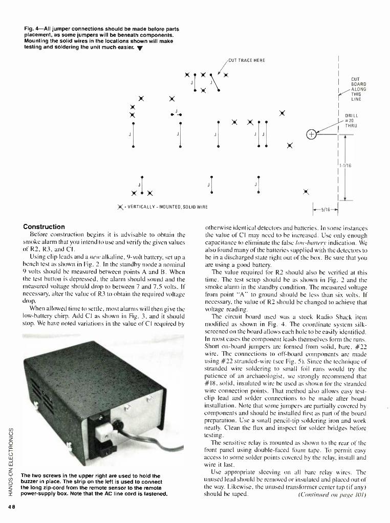
48
Fig. 4 -All jumper connections should be made before parts placement, as some jumpers will be beneath components. Mounting the solid wires in the locations shown will make testing and soldering the unit much easier. y
JI
J
X I X
/CUT TRACE HERE
x Jix
X- VERTICALLY - MOUNTED, SOLID WIRE
Construction Before construction begins it is advisable to obtain the
smoke alarm that you intend to use and verify the given values of R2, R3, and Cl.
Using clip leads and a new alkaline, 9 -volt battery, set up a bench test as shown in Fig. 2. In the standby mode a nominal 9 volts should be measured between points A and B. When the test button is depressed, the alarm should sound and the measured voltage should drop to between 7 and 7.5 volts. If necessary, alter the value of R3 to obtain the required voltage drop.
When allowed time to settle, most alarms will then give the low- battery chirp. Add CI as shown in Fig. 3, and it should stop. We have noted variations in the value of CI required by
The two screws in the upper right are used to buzzer in place. The strip on the left is used to connect the iong zip -cord from the remote sensor to the remote power -supply box. Note that the AC line cord is fastened.
hold the
X
J
X X
J J
X
J1
}(
10-5/16-.I
CUT BOARD ALONG THIS LINE
DRILL =20 THRU
11!16
otherwise identical detectors and batteries. In some instances the value of Cl may need to be increased. Use only enough capacitance to eliminate the false lots- battery indication. We also found many of the batteries supplied with the detectors to be in a discharged state right out of the box. Be sure that you are using a good battery.
The value required for R2 should also be verified at this time. The test setup should be as shown in Fig. 2 and the smoke alarm in the standby condition. The measured voltage from point "A" to ground should be less than six volts. If necessary, the value of R2 should be changed to achieve that voltage reading.
The circuit board used was a stock Radio Shack item modified as shown in Fig. 4. The coordinate system silk - screened on the board allows each hole to be easily identified. In most cases the component leads themselves form the runs. Short on -board jumpers are formed from solid, bare. #22 wire. The connections to off -board components are made using #22 stranded -wire (see Fig. 5). Since the technique of stranded wire soldering to small foil runs would try the patience of an archaeologist, we strongly recommend that #I8, solid, insulated wire be used as shown for the stranded wire connection points. That method also allows easy test - clip lead and solder connections to be made after board installation. Note that some jumpers are partially covered by components and should be installed first as part of the board preparation. Use a small pencil -tip soldering iron and work neatly. Clean the flux and inspect for solder bridges before testing.
The sensitive relay is mounted as shown to the rear of the front panel using double -faced foam tape. To permit easy access to some solder points covered by the relay. install and wire it last.
Use appropriate sleeving on all bare relay wires. The unused lead should be removed or insulated and placed out of the way. Likewise, the unused transformer center tap (if any) should be taped. (Continued on page 101)

MAY 1987 THE NEWSLETTER FOR GROWNUP KIDS
What's Inside. . .
Blanket with a Brain: Quantum's Cordless Automatic 2
It's in Your Hands: The Porta Copy 3
4 Big Feature, Low Price:
Realistic's Linear Drive Turntable 4
Double Your Pleasure: Sharp's Dual -Cas- sette System 5
The Music Maker. Tascam Porta Studio 6
Dated Picture -Taking: Canon's Tele Date 7
Shave on the Run: Braun's Pocket Razor 9
VOLUME XII /NUMBER III
Weak Pulse
PULSE GCRV MOTORCYCLE. Pur- chased from: Hammacher Schlemmer, 147 E. 57th Street, New York, NY 10022. Price: $8,949.
At first blush, the Pulse GCRV Motor- cycle seems an engineering design coup of the first magnitude. A sophisticated electrical system is matched by a high - performance four -stroke engine. The whole package is wrapped in the kind of aerodynamic dream that has had people drooling since before the Jetsons.
The only problem is it doesn't work. The Pulse GCRV is an object lesson
on what happens when engineers allow their theory to outstrip their practice. On paper, the Pulse must have looked grand: a 391cc Yamaha engine, Hitachi CM 11 -54 ignition system, sophisticated fiberglass "jet- wing" two- seater design. No wonder the marketing folks dubbed it a "Ground Cruising Recreation Vehi- cle" -GCRV for short.
That's just where the problem came in. For this is not a "recreational vehi- cle" in the usual sense of the phrase. It is
a racing motorcycle dressed up to appeal to the "must- have" crowd, as in "I must have the latest gadget." As quotidian consumers, these folks are just not pre- pared to deal with Pulse's thorny main-
tenance and repair problems. Marketing the Pulse through Hammacher- Schlemmer is about like marketing an Indy racer through the Sears catalog.
GADGET's problems with the Pulse began on delivery with an incorrect cer- tificate of origin. Additional paperwork snafus resulted in a four -week delay in
registering the machine. Finally, in its first road test, the Pulse stalled out re- peatedly and had to be pushed back to the shop. The problem was diagnosed as overheating.
The Pulse is put together by the Owosso Motor Car Corp., of Owosso, Mich. The standard electronics of the vehicle are nothing if not luxurious: It comes equipped with AM /FM stereo, cassette deck and four speakers. Even the reverse gear is run off the electric starter motor -which, incidentally, had to be replaced after 17 miles, along with most of the wiring behind the dash.
The heart of the problem turned out to be the design of the beast itself. The engineers took a part air- cooled, part oil - cooled engine and wrapped it up in fiber- glass. This permitted the marketing of the Pulse as an "all- weather" motor- cycle, but it also prevented air from cir- culating around the engine. Two fans had to be installed to insure proper cool- ing; even with this additional retrofit- ting, the Pulse never performed ade- quately.
(Continued on page 8)

50
Blanket Statement QUANTUM CORDLESS AUTOMAT- IC BLANKET. Manufactured by: Northern Electric Co., 5224 N. Kedzie Ave., Chicago, IL 60625. Price (Queen Size): $285.
A blanket, electric or otherwise, is a fair- ly inert item. As far as spectacular con- sumer gadgets go, unless it flies, any kind of electronic blanket isn't likely to raise much excitement.
Still, Northern Electric thinks its Quantum Cordless Automatic Blankets are something new in the field. Accord- ing to the company's extensive press lit- erature, electric blanket technology, dat- ing to the 1920s, stayed pretty much the same until the introduction of "a new type of wiring system designed to re- spond to body temperature as well as room temperature." Enter the P.M.- "personal monitoring system" auto- matic blanket, undoubtedly one of the great moments in electric blanket his- tory.
The Northern Electric product, the result of 10 years of research, did away
Cellular Communications? The initial press release a year ago trum- peted, "The world's smallest cellular telephone has been [our emphasis] intro- duced by Walker Telecommunications Corporation's Mobile Communications Division."
The product described was intriguing. "The Walker Pocket Cellular Phone is about half the size of any other portable phone ... powered by self -contained re- chargeable batteries... comfortably fits in either shirt or sports -jacket pocket.. .
most technologically advanced portable phone either available or announced." GADGET's initial inquiries last year met with a straightforward answer: The prod- uct was still in prototype; review units would be made available to the interested press once all the kinks were ironed out and the Walker Pocket Cellular was deemed market -ready.
GADGET waited, but this year the tune changed. No problem with the product, we were told in the course of numerous phone calls to the company's PR firm. Yet there was a reluctance to provide one of the instruments for test and review. Could we send copies of the publication? Could we send background on GADGET? Previous coverage of cel- lular products?
After sending copies of GADGET in its new format as an insert in Hands -On
Electronics, a new objection suddenly surfaced. According to the anonymous public relations processional over the phone, "the readers of Hands -On aren't the kind of audience we care to reach..." We were a little nonplussed, publicity about the Walker Pocket Cellular Phone had appeared in daily newspapers. What was wrong with Hands -On's readership that wasn't wrong with newspaper read- ers?
Following that slap came a letter from Paul Kaufman Associates, Inc. (the prod- uct's PR agency) which reached new heights of apologetics. "I thought it was great that a newsletter as prestigious as GADGETS (sic) was interested in one of my client's new technologies," wrote the firm's Peter R. Schuddekopf. "How- ever, because we're still in the planning stages for publicizing the Pocketphone during the new year, we're all still in a start -up rather than up- and -running mode." So apparently now the product is market- ready, but the marketing plan is still in the prototype stage!
Honest confusion we can deal with. Unexpected technical problems are also nothing to be ashamed of. But a song - and -dance act, variations on the old cor- porate runaround, isn't the royal road to introduction of a new, big- ticket piece of consumer electronics. So, when Walker or Paul Kaufman Associates is ready for GADGET, we'll certainly take their call. We just hope they're able to make that call on the Walker Pocket Cellular Phone. -G.A.
with thermostats, familiar to most elec- tric blanket users as the lumps beneath the surface. The Quantum uses a wiring called "PTC," positive temperature co- efficient wire. Instead of responding as thermostats do to an overheat situation, the PTC system makes it possible for "different sections of the blanket wir- ing...to generate different amounts of heat," in response not only to room tem- perature but to different heat require- ments of different parts of the sleeper's body.
According to Northern, "if for exam- ple, your shoulders or torso area become too warm, the blanket's wire senses this and reduces the amount of heat to that portion of the blanket over those body areas." Quicker warm -up time is an- other claimed advantage.
Equally high -tech is the Quantum's control system. The Queen (84" by 90 ") and King (100" by 90 ") sizes feature dual controls. The solid -state remote controls send data to the blanket heating system via infared beam and each of the bedside units features a digital LCD clock, with alarm and "snooze" set- tings. Some 20 heat positions are of- fered, with a small electronic "beep" generated each time the user sets the con- trols up or down a notch. Finally, the control can be programmed to turn on and off at pre -selected times and to mon-
(Continued on page 8)
Publisher: Al Goldstein Editor. George Arthur Senior Editor. Gil Reavill New Products Editor. Christine Stevens Art Director. C. Giordano Associate Art Directors: Kevin Hein, Rob Weisberg Production: Bill Mudie Administration/Reader Service: Kathryn Hartman Contributing Editors: Philip Eisenberg, Alan Freedman, Jordan Ari Goldstein, Steve Gruberg, Aprile Guarino, John Kois, John Swenson, Ken Swisher, Aaron C. Zimmerman. GADGET is published by A.G. Consultants, Inc., 116 W. 14th Street, New York, NY 10011, (212) 989 -8001. Copyright ©1987 by A.G. Consultants, Inc. GADGET is a registered trademark of A.G. Consultants, Inc. GADGET is published 12 times a year and appears as an insert in Hands -On Electronics, published by Gernsback Publications, Inc., Farmingdale, NY 11735. For information on subscriptions to Hands -On Electronics, please see the magazine's editorial page. Letters intended for GAD - GET's editorial staff should be sent to the newsletter's address as shown here.
GADGET's sole commitment is to its readers. In order to avoid even the appearance of a conflict of interest, GADGET does not accept advertising nor does GADGET solicit gifts or other benefits from manufacturers and retailers who may be men- tioned in reviews.
Page ?/GADGET MAY /1987

Copy Gnat
PORTA COPY HAND -HELD RE- CHARGEABLE COPIER. Purchased from: The Price of His Toys, 9559 Santa Monica Blvd., Beverly Hills, CA 90210. Price: $359.
The hand -held copier appears to be a
product whose time has come. In the past year, three have been introduced, including Sharp's Handy Copier (GAD- GET, April) and the Silver Reed Porta Copy.
After checking out the Silver Reed product, the obvious question was, "why hasn't this been done before ?" It's certainly not a new copying technology, just a new (and smaller) size for an old one. Both the Porta Copy and the Sharp product use the thermal copying process. A leading pre -Xerox method of duplicat- ing, thermal copying has mainly survived in calculator and adding machine appli- cations.
But while using an old copying system, Silver Reed has teamed it with a recent development in image scanning, the charge -coupled device found in such video products as the Sony 8mm cam- corder or the Canovision 8mm system. The result, especially for anyone who recalls the thermally- printed copies of yore, is a surprisingly detailed and crisp image.
Weighing in at 3.8 lbs., the Porta Copy resembles an oversized electric shaver. To copy, a cover is removed from the end, a switch is engaged (cleverly de- signed so it can't be "on" when the cover is in place) and the copier is moved across the material to be duplicated. Out of a
door in the copier's back, a 3.5" wide roll of paper unwinds with the desired image imprinted onto it. A serrated edge
on the paper door makes it easy to tear off the image -imprinted portion.
A print guide (showing the center and outer borders of the copying area) on the business end of the Porta Copy takes the guesswork out of placement. There's also a contrast control and a light which indicates that the battery is charging when connected to a plug -in type re- charger. The Porta Copy's nickel cad- mium battery requires eight hours of charge in order to imprint two rolls of thermal paper.
The rolls, each 33' long, are marketed by Silver Reed in packages of five for a
suggested retail price of $9.95. Supplied accessories for the Porta Copy include a
fabric carrying case, the battery charger and a plastic spool for use with the paper roll. There's also a piece of cardboard
labeled "paper loader" to help guide the thermal paper into position inside the copier.
As might be expected, the Porta Copy works best with straight printed matter. Black and white photos are problemat- ical, while color pictures are nearly inde- cipherable. Copies are nearly (98.4 per- cent of the original) full -size.
On the subject of the Porta Copy's paper, one New York retailer told us she
thought both Silver Reed and Sharp had failed to secure adequate distribution be-
fore putting their copiers on the market. The right size of thermal paper is apt to be difficult to find for a time. In our ex- perience, four Manhattan stationery, of- fice supply and typewriter stores had no supply of the paper.
Applications for the Porta Copy begin to multiply as soon as you get your hands on one. We found it easier to Porta Copy material out of newspapers, particularly when printed in a one- or two -column format, than to cut it out. Various sorts of library research could also be made easier.
Instead of carrying a book or publica- tion to a copy machine (if allowed under the library's rules), a researcher could duplicate desired paragraph(s) right at the work table. Also, businesses in which checks, invoices and receipts are con- stantly copied as well as graphic and fine artists may find the Porta Copy a prac- tical everyday tool.
In using the Porta Copy, we observed two c laracteristics. A steady, medium pace yields the best copies. Likewise, a
hard, smooth surface directly under the material being duplicated gives best re- sults. Copies seem to become less consis- tent as the roll nears its end. The last por- tion of the paper is imprinted with a red line on one margin as a warning that the end is near.
The practical limitations built into a
down- sized, hand -held copier are obvi- ous brit as a refinement, a further appli- catior. of what's become an essential tool in many different fields, the Porta Copy and i.s competitors seem likely to find success in the consumer marketplace. -G.A.
MAY /1987 GADGET /Page 3

Linear Thinking REALISTIC BELT DRIVE LINEAR - TRACKING AUTOMATIC TURN- TABLE (LAB -1600). Manufactured by: Radio Shack, Tandy Corp., 300 One Tandy Center, Fort Worth, TX 76102. Price: $160.
Let's face it, Realistic is not a name which creates instant excitement in glossy audio magazines. Audiophiles don't constitute the bulk of Radio Shack's customers, and you'll seldom see a cover line on one of the audio monthlies, "inside, we test Realistic's new..."
The impression is, however, that's just fine with the Tandy Corporation's man- agement. The company's reputation has little to do with audio snob appeal or up- scale consumerism. That puts the opera- tion so much at odds with the most vis- ible portion of the audio industry, that sometimes interesting surprises are the result, like the Realistic Belt Drive Linear- Tracking Automatic Turntable.
It's a basic unit. But given that a few seasons ago, linear- tracking turntables were both the big noise on the home equipment scene and priced at hundreds of dollars, the LAB -1600 constitutes an exciting breakthrough for those of us with a limited audio system budget.
Linear tracking, of course, means the tone arm moves halfway across the spin- ning disc on a fixed shaft which -as the LA B-1600 instruction booklet expresses it- "keeps the stylus of the cartridge at the correct angle to the radius of the groove over the full surface of the record." Meaning both better audio pickup and less wear and tear on an LP's surface.
The LAB -1600 may be the ultimate non -audiophile turntable, a simply de-
signed unit for someone who just wants to play records and not keep up with the technological Joneses. The drawer -type turntable's controls are simple. Mounted on the front of the turntable itself, a push- button at the far right moves the table in and out of its case. Although the turntable functions in its out -of -case position, in place the LP spins behind a plastic door, with the case providing dustcover -type protection.
A second button begins or stops play. There are also push- button controls for cueing, search in either direction, turn- table speed (3314 or 45 rpm) and disc size -12" or 7 ". Sold with stylus in place, after removing five transit screws from the unit's bottom, the LAB -1600 is ready for use.
In designing the unit, Realistic missed one amenity which would have made a real difference and likely wouldn't have added that much to its retail price. A small light mounted inside the case would have made it possible to search and cue with the turntable inside. As it is, these two functions are best carried out with the table out of the case. Even some
markings on the see - through plastic front (which flips up when the turntable slides in or out) aren't of any real use in positioning the tone arm.
GADGET's test -ordinary daily use of the LAB -1600 over a two -week period -couldn't tell us much about this prod- uct's durability. Given its simplicity of design, and Realistic's approach to con- sumer products, we're guessing this is built to last. Of course, since it's a Radio Shack brand, at least the buyer is assured of finding a service facility if adjustment or repairs are necessary.
Besides the LAB -1600, there's a sec- ond Realistic linear-drive unit, minus the drawer -style design, LAB -2200 with a list price of $140. Radio Shack's catalog also implies it doesn't have this model's "neon strobe and pitch control."
As a first introduction to this recent audio equipment sensation, linear drive, the Realistic LAB -1600 or -2200 are perfectly adequate. While the LAB -1600 isn't destined to be the crown of any lux- ury home audio system, it's a budget - priced, easy- to-operate example of linear turntable technology. -G.A.
Beep Box AUTO -LOGIC AUTOMATIC TELE- PHONE ANSWERING SYSTEM (KX- T1426). Manufactured by: Panasonic Corp. of America, 1 Panasonic Way, Secaucus, NJ 07094. Price: $149.95.
We're not the only observers who think there's a user friendliness crisis in the telephone answering machine market. The little machines are sincerely loathed by many owners and non -owners alike.
Certain professionals we know live in homes littered with the bodies of busted - up answering units. Pretty soon, sociol- ogists should be able to come up with a percentage of Americans who refuse to
leave a message on any machine under all but the most dire circumstances.
Not that the phone answering ma- chine industry is oblivious to these prob- lems. Market studies are regularly car- ried out and, more directly, phone an- swering systems are updated more often than the phrase, "this year's model" can describe.
Panasonic is one of the giants of the industry. The company's "Easa- Phone" line introduced thousands to the conve- niences (and drawbacks) of having a home answering machine.
I'he recently introduced KX- T1426, "Auto- Logic" system is a continuation, and further refinement of the "Easa- Phone." As such, it's got a couple of
(Continued on page 8)
Page 4/GADGET

Dual Cool STEREO RADIO CASSETTE RE- CORDER (WQ- T282). Manufactured by: Sharp Electronics Corp., 10 Sharp Plaza, Paramus, NJ 07652. Price: $199.
The leaps -and- bounds style progress in consumer audio equipment is sometimes downright exhilarating. Its directions are well -established by now. While price and size tend to come down, capabilities and sophistication move upward.
When the portable sound systems la- beled "boom boxes" first appeared, they seemed a product strictly for the youthful end of the consumer market, customers too old for toys, but too young for "serious" audio systems.
In the years since, both the market and the product have grown up. Boom boxes have moved off the streets and school - yards and into family rooms, recrea- tional vehicles and even retirement con- dominiums. Among the most grown -up of these portable stereo systems area trio marketed by Sharp Electronics. GAD- GET looked at the firm's WQ -T282.
At the top of the Sharp line is the WQ- CD15, with a built -in compact disc player, priced at $449.95. The differences between the WQ -T282 and the com- panion WQ -T232 are matters of cos- metic design, power ratings and price. The WQ -T232 is listed at $129.95.
Right out of the box, one of the more impressive characteristics of the WQ- T282 is its sturdiness. Some of the boom boxes on the market are rattle -trap af- fairs, cheaply fabricated and shoddily circuited. This Sharp, in contrast, is both compact and solid. Advertising copy touts its "thicker, high- impact cabinet,"
which besides offering better protection for the mechanisms and components in- side, also "reduces vibration for even clearer sounds at high volumes."
The unit's capabilities include AM, FM and two -band shortwave radio re- ception, tape playback and recording from the built -in radio, other sources (there's a line -in setting on the function selector and RCA connections mounted in the system's top side) and even from a second tape via the WQ- T282's dual cas- sette recorder.
The dual deck system, which Sharp says it invented, is what gives this box its most impressively expanded capabilities. This unit uses the back -to -back config- uration (which the firm also claims to have developed) instead of the side -by- side arrangement of some other systems. This, it seems clear, has some special advantages.
Since both decks are driven with a sin- gle capstan and motor, the speed of the two cassettes is unfailingly synchronized, especially important in dubbing from one tape onto another. The dual- cassette system also allows for continuous play, with tape two engaging at the conclusion of tape one. Deck two incorporates an "automatic program search system," while dubbing can be set for either high or normal speed.
Other features include four -band graphic equalizers, a "four speaker, two way" system, rated at 4.2 watts per chan- nel power output and including separ- ate woofers and tweeters. There's also a built -in microphone and connection port for an external mic as well.
Every silver lining, however, has to have a cloud and there are some limita- tions to the WQ -T282. Deck one will not rewind, fast forward or pause. Dubbing
can't be done silently, although with vol- ume set at the minimum it comes close enough. Finally, the automatic program search system works only with deck two, and takes a near half -page in the instruc- tion booklet to explain.
One curious omission in the directions is any explanation of a function called "beat cancel." Used during recording from the radio, it appears to be a static and noise reduction system. The instruc- tions in the section on "recordings from the radio" merely state, "slide the beat cancel switch to the A, B or C position ... the position allowing the lowest level of interference during the AM, SW1 or SW2 broadcast."
We didn't test the unit's shottwave reception. The Manhattan location of GADGET's offices, experience has taught us, makes those bands practically inaccessible. The WQ- 7282's reception capabilities (via a telescoping antenna) undoubtedly aren't designed for the crowded ozone of urban centers.
Another slight objection was regis- tered by a GADGET staffer who has one of these systems at home. Besides point- ing out that use of the dual -cassette system was at least confusing (close study of the relevant section of the in- struction booklet will pay worthwhile dividends), his unit also refuses to record in stereo, possibly a correctable defect.
Overall, however, the WQ -T282 is a superior portable sound system. Sturdy, boasting impressive portable audio fidel- ity and range, as well as a multiplicity o' functions and applications, this Sharp Stereo Radio Cassette Recorder is a ma- ture expression of a still developing con- sumer technology -and maybe even an indication of more and better to come. -G.A.
MAY/1987 ßADOETIPage 5
53

54
Studio to Go TASCAM PORTA -ONE 4 -TRACK RE- CORDING SYSTEM. Manufactured by: Teac Corp. of America, 7733 Tele- graph Rd., Montbello, CA 90640. Price: $595.
Having shaped the reproduction and transmission of music during the past quarter century, today, electronics are reshaping the production and even the basic vocabulary of the art. Studio re- cording processes, which a few years ago were available only in the most advanced of installations, today are being brought to the home musician on a budget basis.
The Tascam Porta -One 4 -Track Re- cording System, manufactured by a divi- sion of the Teac company permits a musician to record him or herself playing an instrument, or a portion of a compo- sition. Then it is possible to go back and add another instrument through "over- dubbing," that is adding another track to an existing one in order to create a third track combining the two separate recordings. Thus, with the Porta -One, which Tascam also calls a "mini- studio," one person could play the drums, guitar, bass and also vocalize by recording each element on a separate track, then synthe- sizing a final recording via the output of
the Porta -One connected to any tape deck.
It's not necessary to do each recording separately, however. The unit functions as a mixer, in addition to being an over- dubbing tool. The Porta -One can handle up to four simultaneous inputs.
They're sent through a mixer with a nominal (two -band) equalizer and then all the inputs can be recorded onto a sin- gle tape. If a musician were to play four instruments at once, recording them all onto a single track, they could eventually be mixed into a final product featuring 16 -piece instrumental accompaniment.
The process which makes this possible is fairly straightforward. On an ordinary cassette tape, there are four tracks -side one left, side one right; side two left and side two right. The Tascam uses all four of these available tracks simultaneously. This also means that the Porta -One user can employ standard tape cassettes. The system is armed with dbx, so tape hiss is reduced almost to the point of disap- pearance.
A synthesizer player would find the Tascam an extremely valuable mixing and recording system. Most high -quality synthesizers can't generate more than one "instrumental" output at a time. With a four -track system at his or her disposal, a synthesizer musician could mix several different sounds, or instru-
mental outputs, then add percussion from a drum machine, producing a sur- prisingly sophisticated final recording.
Tascam is only one of several compa- nies marketing these four -track record- ers, but its product is one of the best available. For anyone needing or desir- ing more than four -track capacity, a technique dubbed "ping -ponging," ex- plained in the Porta -One manual, lets a user record as many as 10 different tracks onto a single tape with only a minor sacrifice of audio quality.
Not the least of the Porta -One's at- tractive features is its extreme compact- ness. Roughly the size of a thick loose - leaf binder, it operates off of five "D" batteries, making it portable in more than name.
Most of the Porta -One's controls (bal- ance, equalizers and volume) are flat, circular dials, so they are unlikely to be moved accidentally. Each track has a VU meter, and the system is designed so that the dials can be illuminated.
The Tascam Porta -One 4 -Track Re- cording System is convenient to use and produces final recordings of more than acceptable quality. If it costs a little more than some of its competitors, the extra few dollars buy an excellent exam- ple of today's portable, and personal, professional audio recording technol- ogy.- A.C.Z.
Pegs fi/GADGET MAY/1987

Dated Photos SURE SHOT TELE QUARTZ DATE CAMERA. Manufactured by: Canon U.S.A., Inc., 1 Canon Plaza, Lake Suc- cess, NY 11042. Price: $386.
Despite the widespread impression that Americans spend their waking hours watching VCRs, listening to CDs, cam - cording their families and friends, plug- ging into Walkmans and using their home computers, there are still a lot of people interested in the plain, garden - variety snapshot. There are even those who don't much care for Polaroid's in- stant picture devices, they just want clear, colorful photos of family, friends, places and things.
Of course, time doesn't stand still in any product category and if your last en- counter with a camera was with a Kodak Brownie, you'd be surprised at the changes that have taken place in ama- teur picture- taking. Canon's recently introduced Sure Shot Tele Quartz Date Camera is as easy to use as the simple picture- taking devices of yesteryear. At the same time it boasts features which, until now, weren't available even on ex- pensive professional cameras.
The feature which is part of the cam- era's lengthy moniker -"quartz date" -is a good example. An automatic function (which can be disengaged) prints either the year, month and day or the date and time when a photo is taken in the lower left corner of each expos- ure. An LCD panel on the camera's back can also indicate when the film in- side was loaded.
Another not -like- the -old -days feature is a compact adjustable lens, complete with wide angle and telephoto settings. According to Canon, and GADGET's test, at the push of a button, the 35mm Sure Shot auto focus lens converts from a 40mm wide angle setting to a 70mm telephoto lens, ideal for portraits or ac- tion shots when it's not possible to get close to the subject. Canon has also in- cluded features, the firm explains, which "give the user more creative freedom than is usually possible with fully auto- matic cameras."
For example, double exposures don't have to be a mistake. Recall how some- times forgetting to advance the film after taking a photo can create an interesting shot? The Canon has a button which tells the camera not to advance. In combina- tion with a supplied "multiple exposure adapter" which fits over the lens, this makes possible a variety of special ef- fects. There's also a "soft" filter (for studio -style soft focus portraits). An "exposure compensation button" makes
it possible to "compensate two f /stops for backlit situations in which there's a possibility that foreground detail will be lost." A green lamp inside the viewfinder indicates that the subject is in focus.
Yet another nice built -in feature is the Sure Shot's self- timer. Ten seconds after being set, it releases the shutter, allow- ing the photographer to be part of the photo.
Automatic film loading and advance are reminders that the Sure Shot Tele
Quartz Date is a camera for amateurs. Exposure is also automatic (meaning no lens setting or shutter speed decisions to make) and the camera even decides whether a flash is necessary or not. Auto- matic shutter speeds range from '/ sec- ond to 1 /500 second. The camera even automatically rewinds the film.
Power for this 35mm camera comes from a lithium battery which Canon says, "can last for as long as five years under normal usage -eight rolls of 24- exposure film per year with the flash used for about 30 percent of the expos- ures." An indicator tells the user if a bat- tery is low and due for replacement. An- other replaceable component is the multi -duty liquid crystal display, about which the instructions caution, "lack of contrast or blur in the digital display may occur after five years of normal use." Replacement is "at owner's expense."
Also noteworthy in our test was the camera's shape. A nicely contoured right -side grip (with the shutter release mounted on top) makes "one -handed operation possible," if you're right - handed. More importantly, it makes the camera a comfortable one to grip.
The Canon Sure Shot Tele Quartz Date worked with all the reliability of the simple box cameras of the past, while its features and functions were easily under- stood and used. Not only are the cam- era's various controls and signals exceed- ingly well indicated, but Canon deserves high marks for a model instruction booklet.
This seems to us to be a perfect travel camera, not only because of its compact size (5'/" wide, 3'/" high and 21/2" deep) and light weight (16.2 oz.), but because of its lack of cumbersome sep- arate accessories like detachable flash or timer. The camera is sold with its case, battery, neck strap and "multi -image adapter."
Some may find the LCD -style numer- als and letters in each photo's corner ob- trusive, in which case the user has the option of turning off the date function, or buying what's essentially the same Canon camera without the dating device -the Sure Shot Tele priced at $350.
The pictures produced by this camera were consistent and well -balanced. Even nighttime shots, illuminated by the flash and outside, incidental lighting, were clear and recognizable. To sum up, this Canon Sure Shot is a sophisticated camera you don't have to be sophisti- cated to use. It's just the automatic camera to use in getting candid shots of the family watching the VCR, listening to the CD player, plugging into Walk - mans and hunching over the personal computer- devices this reliable auto- matic camera easily equals in its con- temporary styling and up -to -date func- tions and features. -G.A.
GADGET/Page 7 <á
v
55

5 s
PULSE (Cont. from p. 1)
But the litany of problems encoun- tered by GADGET's testers did not stop there. We found it difficult to maneuver the machine, which had an unsettling herky -jerky steering style. Visibility was a major vulnerability: It was difficult to tell, once cocooned inside the cockpit, where the machine actually "ended,"
i.e., where the jet -wings were for clear- ance purposes, or even how far the nose cone projected in front of the vehicle.
Of course, some of this was just being new to the machine, but it struck us that the Pulse is unweildy in the hands of a beginner. We wouldn't want to be on the streets with a driver new to the motor- cycle. And the difficulties seeing through the Plexiglass, the glare from the dash- board, the ineffective windshield wipers are all visibility problems that won't dis-
appear with practice. We suggest that the marketing people
behind Pulse lose their fantasies about a "commuting motorcycle," an "all - weather motorcycle," a "recreational vehicle" and call Pulse what it is -a delicate racing machine. As a precondi- tion to its sale, we also suggest a mech- anic's certificate -and proof of access to a racetrack, where the bugs can be worked out of the Pulse without danger to the rest of us. -G.R.
AUTOMATIC BLANKET (Cont. from p. 2)
itor and adjust the heat for the right, left or entire blanket area.
GADGET's tester thought it might have been a good idea for Northern to offer an illuminated temperature setting control, although the "beep," as well as the raised gradations on the remote are meant to do away with the need for light.
In all important aspects, she found the Quantum to be as advertised, although its sensitivity to individual body heat and surface temperatures wasn't something she could attest to. Setting the blanket higher than the company's suggested ini- tial heat level (4.5), she also thought that the Quantum would keep you toasty even set down at 2.5. It does put out the heat.
As for its faster heat -up time, she had minor doubts about that. Her extremi- ties heated up in response to her body temperature, but it wasn't as fast a pro- cess as the instructions led her to believe.
As houseware, GADGET judged the Quantum to be a superior blanket - washable, tuckable, not flimsy and with a circuitry that the user isn't aware of (those lumps mentioned earlier). North- ern, in fact, offers a five -year warranty, which has to count as some testimony to the firm's faith in its product.
The Quantum systems are protected by patents, so this is something unique among electric blankets. While we might not go so far as its manufacturer and dub this, "the blanket with a brain," GAD- GET did find it an elegant, functional, update of this standard piece of bedtime comfort equipment. -G.A.
ANSWERING MACHINE (Cont. from p. 4)
capabilities and some touches in its design which aim to put it in the van- guard of consumer acceptance. Already, some of New York's discount electronic outlets have stacks of the KX -T1426 in anticipation of brisk demand.
"Augo- Logic" operation, according to the instructions, includes automatic rewind of the machine's tapes, message play, including "stopping at the last message and resetting itself at the touch of one button." The unit also features tone remote control, which allows the owner, using a touch -tone phone, to call the machine for playback of messages, re- recording of the outgoing message, leaving "marker messages," turning the machine on or off and /or via the tele- phone, "room monitoring." This last feature is a home security application which seems a good, no- frills use of ex- isting capability in a new capacity.
The KX -T1426 liquid crystal display shows time and number of calls received
and messages recorded, while there's also a voice synthesizer to announce the time of day, message recording time and number of calls. Two -way recording al- lows the user "to store conversations for later reference," while an automatic dis- connect feature stops the unit from func- tioning if an extension telephone is answered.
The KX -T1426 also allows the user to sample the recorded outgoing message, has a system for confirming that the unit is ready to record and is accompanied by a very detailed instruction booklet.
All well and good says the answering machine bigot, so how come even with that "detailed instruction booklet" we never got the KX -T1426 its wonders to perform? And what about the three dif- ferent trips to the electronics store to purchase adapters in order to connect the machine to a pre -modular phone sys- tem? Panasonic seemed clear enough on what sort of adapter was needed, but every electronic retailer had a different configuration which nearly fit the oper- ating instructions' diagram. The result,
$7.45 in research expenses and an an- swering machine which made a good liv- ing room clock.
The answering machine initiate says that none of these problems occurred during her test. After she figured out there was a separate power switch, the KX -T1426 allowed itself to be pro- grammed from another phone, took messages, announced their number and played them back in order.
Let GADGET be the first to call for a Geneva Convention for answering ma- chine manufacturers, suppliers of elec- tronic watches, and all programmable consumer devices. The conference, maybe under the auspices of the United Nations, would draw up an international protocol of programming sequences, signals and accepted symbols for func- tions, procedures and the like. A Ge- neva -based office could ensure that both machines and instructions were in conformity with the protocol. That's one international agreement guaranteed to do away with a lot of unnecessary hos- tility.-G.A.
Page 8/GADGET MAY/1987

Seashore and lakeside will soon beckon as summer approaches. Two modern -day necessities for fun in the sun are music and refreshment. So why not combine a triple -insulated beverage cooler and an AM /FM radio into a single package? That's exactly what Sun Hill Industries (Glendale Commerce Park, 48 Union St, Stamford, CT 06906) has done with its new Cool Sounds. Large enough to carry two six-packs of beverages and lunch, the Cool Sounds also incorporates a battery -powered radio with a high - quality speaker (in addition to a supplied headphone set) which is both sand and water proof. This fun accessory is made of bright, red nylon fabric, trimmed in blue and is collapsible for space- saving storage between trips to the shores of your choice. There's even an outer pocket for suntan lotion, a deck of cards or whatever. Price: $34.95.
If you've been thinking about becoming a camcorder owner, Maxell Corp. of America (60 Oxford Dr., Moonachie, NJ 07074) has something especially for you. It's called the Maxell Starter Kit and "contains all the accessories necessary to get started in home videotaping, including a nickel cadmium rechargeable battery pack, Maxell videotape, in either VHS -C or 8mm format and a handbook" offering "tips on camcorder recording" as well as a carrying case for the kit. Ready, set, camcord. Price: $79.95.
If you've got any room left after stowing your pocket radio and your pocket calculator, pocket cellular phone and (remember this one ?) pocket fisherman, you may want to add the recently introduced Pocket Battery Shaver (model 5526) from Braun, Inc. (66 Broadway, Rt. I, Lynnfield, MA 01940). Claimed as "smaller than a pack of cigarettes," the 5526 operates on two "AA" batteries for 70 minutes of what Braun calls "independent shaving." The shaver also incorporates a guard cap which houses a cleaning brush and protects the shaving head's "ultra -thin platinum -coated foil." A built -in switch lock keeps the Braun off when it's not in use. Especially ad- vised for "a fast, comfortable second shave of the day," the Pocket Battery Shaver carries a two -year warranty. Price: $24.99.
Even plumbing is going digital nowadays with the Digital Display Bath- room Faucet, available from Hammacher Schlemmer (147 E. 57th St., New York, NY 10022). A built -in sensor measures water temperatures from 50 to 130 degrees Fahrenheit, with both heat and water volume controlled with a single lever. The digital read -out and temperature measurement components are powered by ambient light, so there is no risk of electrical shock. A lith- ium battery provides auxiliary power in low -light conditions. These Digital Display Bathroom Faucets are available in a bath set, lavatory set and a shower valve only, in either brass or chrome. Price (depending on set): $149.50- $259.50.
With camcording on its way to becoming a national electronic pastime the floodgates of video accessories are wide open. Herrington (10535 Chil- licothe Rd., Kirtland, OH 44094) offers the Camlight for shooting video- tapes indoors and avoiding the disappointment of washed -out color, murky details and fleshtones rendered in "a ghoulish pall." Weighing only 7 oz. and just 33/4" long, the Camlight mounts on your camcorder or can be used as a free- standing light. It puts out what the catalog calls "a brilliant arc of color -balanced light" and runs on standard household current. It can also use an optional 12 -volt DC adapter for battery pack operation. Extra quartz halogen bulbs, in either 150 or 100 wattage, are also available. Price: $89.95.
We think we've discovered a new audio term, at least it's the first time we've run across it. International Jensen (4136 N. United Parkway, Schiller Park, IL 60176) has introduced Home Speakers it's calling "CD ready." It seems the model 3100 speaker has a midrange and tweeter which include a
"special edge -dampening treatment for smooth, accurate response." The speaker is "vented for very efficient, extended bass response" and features "greater dynamic range capability," all of which adds up to being "CD ready." The floor -standing unit has a 10 -inch, three -way speaker and is designed with "the drivers mounted higher than usual and on a lengthened base so no stands are necessary to raise the drivers." The 3100 also features a black, fabric grill and (probably more importantly) a five -year unlimited warranty. Price: $169.95.
Cool Sounds Cooler /Radio
Pocket Battery Shaver
Camllght
"CD Ready" Speakers
MAY/1987 GADGET/Page 9
D
m
5 7

58
We don't pay much attention to design trends in the world of major appliances, but Whirlpool Corp. (Benton Harbor, MI 49022), says some- thing new is stirring atop the familiar Kitchen Range. The company has just introduced two new stoves, the RF387PXP and the RF367BXP, which incorporate "the European style of solid elements." The "cast iron solid cooking elements" owe their popularity to "ease of cleaning, sleek look and even heat distribution." Other features of these otherwise All- American ranges include self -cleaning oven, custom broil control, Panoramic glass oven door and a removable storage drawer. The RF387PXP also includes Whirlpool's Mealtimer clock. Price: $550 -$630.
Whirlpool Kitchen Range
ITK503 Telephone /Clock Radio
Factory Miniature Office Tools
Some people call them food warmers, others call them electric steamers but whatever the label assigned, they're a useful kitchen accessory. Toshiba (82 Totowa Rd., Wayne, NJ 07470) has just added two new Automatic Rice Cookers/Steamers, the 10 -cup capacity RC -380B and the six -cup RC -320B. Both units, Toshiba says, "will cook rice evenly and are ideal for steaming vegetables, seafood, poultry for salads and casseroles." The steamers each come with a trivet and (here's a big plus) are "packaged in an attractive four -color box." Price: $49.95- $59.95.
If your audio enthusiasm and equipment have outrun your system's capa- bilities, the Adcom Speaker Controller may offer some relief. The device allows three or six pairs of speakers in any combination, including simul- taneously, to be run through an audio system. A load protection circuit guards against amplifier damage. Both the three -speaker and six- speaker controllers can handle more than 200 watts per channel. Herrington (10535 Chillicothe Rd., Kirtland, OH 44094) calls them "well- engineered, with heavy -gauge, black finished metal chassis." Price: $99- $159.95.
Off -beat combos are one of the hallmarks of gadgetry. Sony (Sony Dr., Park Ridge, NJ 07656) has come up with a Telephone /Clock Radio (IT- K500) as its newest contribution to the tradition. Part of the company's "dreamline" digital clock radio series, the IT -K500 offers speakerphone operation and a 15- number memory for frequently dialed numbers. It also features a bright blue illuminated digital display, sleep timer and dream bar, a feature that offers alarm wake -up signals in eight- minute intervals. The built -in AM /FM stereo automatically mutes when the telephone's handset is raised. Other IT -K500 phone features include redial, ringer volume and tone control and "large push- button dialing keys." A good bedside table unit, the IT -K500 is available in gray and can be wall mounted. Price: $129.95.
It was 15 years ago that Hewlett- Packard (P.O. Box 10301, Palo Alto, CA 94303 -0890) introduced its debut hand -held Scientific Calculator, claimed as the world's first. This year, H -P celebrates by introducing what's believed to be the first calculator capable of doing symbolic mathematics. The HP- 28C can "go beyond numeric calculations to use symbols or variables." Problems can be solved conceptually and numbers can be plugged in later. Hewlett -Packard proudly calls the HP -28C, "the most significant contribu- tion to hand -held computing since the electronic slide rule." The calculator features a four -line, 23- character LCD display on which "complex num- bers, matrices, vectors, lists, algebraic expressions and other data" can be viewed. On- screen menus and soft keys give the user "keystroke access to hundreds of functions." Designed for scientists, engineers, students and math and computer specialists, the HP -28C may well be beyond GAD - GET's mathematically underdeveloped ability to test it. Price: $235.
With tongue firmly in corporate cheek, Plus U.S.A. Corp. (10 Reuten Dr., Closter, NJ 07624) is calling its pocket -size compendium of office tools, "the ultimate portable office." Called The Factory, the "Swiss Army Knife" style unit contains "the world's smallest stapler," a hole puncher, stainless steel "ambidextrous" scissors, a magnifying lens, a retractable tape measure, a stainless steel knife, screwdriver, straight edge rule, storage com- partment and an all- purpose cutter. What, no copying machine? This "com- plete miniaturized set of office tools" is available in various colors including red, white, blue, yellow or black. Price: $29.95.
Page 10IOADGET MAY/1987

Electronic pagers can be many things, like intrusive, obnoxious and irritating. Motorola (Communications Sector, 1301 E. Algonquin Rd., Schaumburg, 1L 601%) has introduced one which it says is "ultra corn- pact." The Bravo Numeric Display Pager weighs a mere 3 oz. Users can select the signal of their choice, the customary "beep" or a shorter "chirp." For $20 extra, the Bravo will even emit a "vibra- page," in which message alerts are received in silence. Instead, vibration and a visual signal are gener- ated by the unit. "Group call" makes it possible for the pager to be one of several receiving the same message simultaneously. There's also a "multi - source identifier," which can be programmed to "identify familiar message sources." "Duplicate message detection" guards against depleting the pager's electronic memory with storage of duplicate messages, and there's a low power monitor. Price: $271.
Diet accessories are like diets themselves. There always seem to be new and "better" ones around. Nutritional Designs (3379 Shore Parkway, Brooklyn, NY 11235) has just introduced a new Food Scale aimed at mak- ing portion control easier for dieters, diabetics and health -conscious Amer- icans of all kinds. Claimed as accurate to an eighth of an ounce, these nutri- tional scales will weigh up to 8 oz. of food. Compact and durable for use away from the home, they feature a removable tray for easy cleaning. The model 9000 features a "foldable scale for travel" and weighs a mere 8 oz. itself. The model 8000 features a digital read out and operates on six "AA" batteries or a 9 -volt AC adapter. Price: model 9000-$24.95; model 8000- $49.95.
Here's an item we're pretty sure would make life at GADGET newsletter a whole lot easier, an Electronic Spelling Dictionary, available from Ham - macher Schlemmer (147 E. 57th St., New York, NY 10022). This hand -held computer, "approved by Merriam- Webster, the most authoritative publisher of American dictionaries," has a memorized vocabulary of 80,000 words. If the user spells the word correctly, the Electronic Dictionary confirms it. If the spelling is wrong, the device offers the correct alternative. A special "crossword puzzle feature" allows the user to "enter a word with blank letters, with the spelling checker offering "a list of completed words that fit the pattern." The vocabulary includes abbreviations and proper names. Weighing 8 oz., power is supplied by four "AAA" batteries, included with the purchase. Price: $94.50.
It figures that it would be the Sony Corporation (Sony Dr., Park Ridge, NJ 07656) which would come up with a new approach to CD automatic changers. It also figures that the firm would come up with a good name for its CDP -05F CD Changer Player, the Disclockey. Instead of the magazine- style changer, the new Sony features a "built -in five -disc carousel," which is supposed to "greatly reduce disc -to -disc access time and simplify overall operation." The unit is also claimed as the first to "offer consumers disc magazine compatibility between home and car systems." One to five discs can be loaded into the CDP -05F, while CD changing time is "just two to three seconds." Listeners are offered four different program repeat modes and the DiscJockey can be operated remotely using a supplied wireless infrared control. Price: $450.
Here's a variation on the personal TV theme. From Citizen (1200 Wall St., W Lyndhurst, NJ 07071), the IOTA LCD TV is one of the firm's black - and -white miniature sets, outfitted with a speaker system (in addition to the supplied earphone) and designed to hang on the wall. Our advice would be to hang it where the viewer can get close to the 3.5" screen at eye -level. The picture generated is, unfortunately, marginally acceptable, as usual for LCD TV technology. Care should also be taken that the IOTA's telescoping an- tenna is positioned for unobstructed reception. LCD technology, we hope, marches forward, but it still hasn't gotten there. Power is supplied by four "C" batteries and optional AC and vehicle adapters are available. Price: $149.95.
Numerk Display Pager
Electroric Spelling Dictionary
Sony CDPC5F DlscJockey
IOTA LCD TV
MAY/1987 GADGET/Page 11 ïa a
59

60
Travel Curler Console
Biofeedback Programs
HI -FI Video Camera /Recorder
Here's a useful traveling item for persons concerned about their coiffeur, the Slim Travel Curler Console. The device folds to less than 2" thick, in- cludes a built -in mirror and heats 10 large and 10 medium rollers in about 15 minutes. Available from Hammacher Schlemmer (147 E. 57th St., New York, NY 10022), the Slim Travel Curler is made of high- impact plastic, and includes a 6' electrical cord which plugs into any standard wall outlet. It weighs 31/2 lbs. Price: $39.95.
A couple of years ago, GADGET covered the products of Thought Tech- nology Ltd. (2180 Belgrave Ave., Montreal, P.Q., Canada H4A2L8), a manufacturer and developer of Biofeedback Programs (GADGET, March '85). Now Thought Technology has introduced four brand new programs - designed to help users stop smoking, cope with stress, lose weight and con- trol insomnia. They're the result of the company's "collaboration with ex- perts in...smoking cessation, weight control, sleep disorders and stress con- trol." Each program uses an audio cassette to give "instructions in deep relaxation techniques" in tandem with a device called the "GSR2," for "galvanic skin resistance" monitor. This allows the user to monitor his or her progress in reaching "deep relaxation." The programs are distributed by Sears Roebuck and Co. among others. Price: $69.99.
The Pine Cone (Blake Building, P.O.B. 1378, Gilroy, CA 95021) boasts that its new Atlas 3" stereo speaker is "a giant in sound quality," offering "high- fidelity symphony hall sound," although it weighs only 7 oz. and "will slip comfortably into pocket or purse." Among uses suggested for this "stereo wonder speaker," connected via the headphone jack, is listening while "working, walking, jogging, at the beach, sailing." Pine Cone offers a 30 -day guarantee, which in the news release is called a "guarantee." Price: $9.95.
Here's an audio accessory for the rock -'n' -roll generation, which today seems to be anyone not confined to a nursing home. The Phase Coupled Activator digitally reconstructs low bass, lost during the recording process, so records, tapes and FM will sound "as exciting as the real thing." Her- rington (10535 Chillicothe Rd., Kirtland, OH 44094) says this is not an equalizer, but rather the PCA, "puts out clean, punchy bass, with impact you'll feel in your gut, and through the soles of your feet (really!)." The device adds "no distortion" to your audio system, instead digitally recon- structing "how real bass feels at a concert. So if you like the 'thud' of a bass drum in your stomach, give it a try!" We just hope our upstairs neigh- bor doesn't buy one. Price: $259.
Combining at least two of the current trends in consumer video, Zenith Electronics Corp. (1000 Milwaukee Ave., Glenview, IL 60025) has intro- duced what it calls "the first Camera /Recorder with VHS hi -fi stereo audio." The new VM7100 weighs 5.3 lbs., uses standard VHS cassettes and features "a full- featured playback deck that can serve as another VCR for bedroom, motor home or boat." Other features include autofocus with a 6:1 power -zoom lens, low -light recording capability, four video heads and two audio heads, fade, zoom and dub functions, a built -in stereo micro- phone and up to 8 hours of recording at "extended play" speed. The VM7100 also includes "high quality" (the video industry's "HQ ") circuitry. Price: $1,795.
Coming in June's GADOVI newsletter Multivision 3.1 -A digital add -on for any television which will give your set
impressive features and capabilities (yes, we said any TV). The VCR Rabbit -An image multiplier that allows your VCR to send its
program to televisions throughout the house. The CGS -A thermoelectric "compact silent generator" which brings elec-
tricity to campsite, camper or any other unelectrified location. Also in the next GADGET -Casio's TV -2000, Canon's Faxphone, Toshiba's newest microwave oven, sweet musical dreams with a "stereo pillow," VentuResearch's water -activated time- pieces and some surprises, all in the June GADGET newsletter.
Page 12/GADGET MAY/1987

Fluke Model 52K /J
Thermometer
A computerized thermometer? Yes! And it really does things differently
THERE ARE SEVERAL WAYS 'l'EM- perature can be measured. Among them are heated gas, mercury column, bi -metal spring, solid -state devices, and the ther- mocouple. Most likely, the one with which you're least familiar is the ther- mocouple, the sensing device used in Fluke's Model 52 K/J Thermometer.
It's the K/J designation that tells us something's different about the Fluke 52 because K and J are the designations for two kinds of thermocouple temperature sensors. To help you more easily under- stand what the Fluke 52 is all about, let's take a quick look at the thermocouple.
Electric Generator In simple terms, a thermocouple is a
device that produces a temperature-re- lated electrical output voltage. Although the active element and its metallic protec- tive housing might be no larger than the head of a pin, it produces a voltage value that can be indicated on a conventional voltmeter. Calibrate the meter readings in terms of temperature and we end up with a very reliable and stable thermometer.
Why, you might ask, should we go through the complexity of a thermocouple when we could perhaps just as easily use a conventional thermometer? Because, if the thermocouple's housing can with- stand extreme heat and cold, or corrosive chemicals, we can easily measure tem- peratures that would cause other ther- mometers to shatter, melt, or dissolve.
Several kinds of thermocouples are used to accommodate hostile environ- ments. The most common are the K and 1
types, both of which can be used with the Fluke Model 52.
Computerized Thermocouples Thermocouples are supplied in various
kinds of housings; some are acid resistant, others are intended to be liquid stirrers, some are pointed so they can be plunged into foods (such as the holiday roast beast), still others are wands for measur- ing the temperature of air streams and drafts, and there's even a surface -sensor
for measuring the temperature of -you guessed it-the exposed surface of just about anything.
Many kinds of thermocouple devices can be plugged into the Fluke 52 because thermocouples use standardized con- nectors. There is even a broad selection of probes specifically intended for the Fluke 52, but that's getting ahead of ourselves.
Two Sensors The Fluke 52, which is powered by a
transistor -radio type 9 -volt battery, has an LCD display for temperature readings, operating functions, and error indication. It is supplied with two bead -type sensors having a maximum temperature rating of 500 °F for both the thermocouple bead and its Teflon lead insulation.
The meter itself has two separate sensor inputs. Eight selector pushbuttons are provided for the various functions; they are: (1) power on/off; (2) display in °F or °C; (3) input and temperature of the TI input; (4) input and temperature of the T2 input; (5) differential reading between in- put readings (TI - T2); (6) record mode (it stores the minimum and maximum temperature readings); (7) view mode (which toggles the reading between the MIN and MAX readings); (8) hold mode (which "freezes" all temperature mea- surements).
All modes, as well as the temperature readings and the battery's condition, are indicated on the display, which has tem- perature- display characters of approx- imately 0.5 -inch. Even the thermocouple type plugged in to each input is indicated. The meter is internally adjusted to default
(Continued on page 97)
Special probes are optional accessories. This group includes the surface sensor (top). immersion probe (middle). and the air probe (bottom). The air probe has its protective tip (black) installed.

Fig. 4- Assuming that a pickup arm is correctly designed, and the cartridge correctly fitted, optimum tracking can be obtained if overhang is specified by the manufacturer.
+3°
+2°
+1°
5 (INCH)
0°
-1°
2 60 80 100 120 140 (mml
Fig. 5-The published tracking error curve for a Technics phono deck using a conventional S- shaped pivoted arm. It
would be typical of other 230mm (9 -inch) pickups.
DYNAMIC -BALANCED TYPE
COUNTERWEIGHT
PIVOT 2111111 1-.
STATIC BALANCED TYPE
COUNTERWEIGHT
PIVOT
241
CARTRIDGE CARTRIDGE
A B
Fig. 6 -Fully dynamically balanced arms rely on a spring (A) to provide tracking pressure. Most rely on gravity for the playing weight (B). even if dynamic balance is compromised.
PIVOT
8 1 CENTER OF RECORD
V /STYLUS
Fig. 7 -The drag on an offset head is out of line with the pivot, which tends to pull the pickup inward -so. anti -skat- ing bias is needed to equalize the pressure on groove walls.
While there may seem to be little point in striving for that capability, the fact is that, in typical listening rooms, vibra- tion from footfalls and high -power bass loudspeakers can nudge phono decks and produce spurious sonic effects. By stabilizing the pickup arm, dynamic balance helps to mini- mize the problem.
Straight arms, with offset heads, like that illustrated in Fig. 3A, lend themselves to dynamic balance, relying on a spring to apply the requisite playing force to the stylus. Most man- ufacturers, however, tend to favor J- or S- shaped arms - particularly, the latter -for their ability to accommodate in- terchangeable shells and cartridges. Dynamic balance can still be a design objective, while tolerating sufficient residual unbalance to allow the playing weight on the stylus to be determined by adjusting the counterweight (Fig. 6)- claimed to be more predictable than a spring system.
A complication of any offset head is that the drag of the groove on the stylus (point "A" in Fig. 7) is in line with the head rather than with the pivot (dotted line). As a result, it
tends to pull the arm inward (toward point B), increasing the stylus pressure against the inner groove wall. The side -thrust is said to average about 12% of the stylus playing weight and is greatest at the outside of the disc, because of the greater groove velocity.
To offset the side -thrust, quality phono players include anti -skating devices of one kind or another, intended to swing the arm gently outward. In Fig. 8A, a small weight and a nylon thread serves the purpose; in Fig. 8B, a weight and a couple of small levers achieve a similar result. But in Fig. 8C, a spiral spring is fitted in the base, with a knob allowing the anti- skating bias to be adjusted according to the selected playing weight.
Moving Mass While it is usually possible, by means of a spring or a
counterweight, to achieve static balance and correct playing weight with arms, headshells, and cartridges of relatively high mass, another problem has to be considered, namely that of moving mass.
The greater the mass of the above components, the greater their inertia and the effort either to initiate or restrain move- ment. For example, in the presence of undulation or eccen- tricity in the record grooves, the effort needed to lift the head or move it sidewise may be sufficient to displace the can- tilever of a high -compliance cartridge from its normal median position, resulting in higher distortion.
A lightweight cartridge and headshell -with the counter- weight wound in closer to the pivot -presents less of a problem. Similarly, lightweight arms are preferred, although the design and the material used in their construction must provide adequate rigidity and relative freedom from structural vibration modes.
Bass Resonance In that general context, consideration also has to be given
to the natural mechanical resonance (which occurs between the mass of the arm, etc.) and the compliance of the stylus system.
If a highly compliant cartridge is fitted to a high -mass moving system, the resulting resonance may end up some- where below 6Hz. As such, it will tend to accentuate the
effects of record warp, etc., limiting the ability of the car- tridge to track the groove and/or pumping the woofer loud- speakers.

At the other extreme, a low- compliance cartridge in a featherweight arm may result in a resonance at or above I6Hz; adversely affecting the reproduction of low -end bass. In many arms, the counterweight is attached to the arm itself by a resilient support that's intended to reduce the "Q" -and therefore. the severity-of the overall system resonance.
Arm Suspension With the progressive refinement of groove, stylus, and
cartridge technology, it is essential to ensure that the vertical and horizontal pivoting arrangements for the arm are as near to friction -free as possible. At the same time, they must support the arm positively and firmly, so that the player will be practical and reliable as a consumer product.
Simple bushed bearings are unacceptable, as are the one- time mechanical trips and levers of mass- produced automatic players and record changers. Modern high -quality decks may, indeed, offer automated play facilities but using optical or electronic sensing rather than mechanical trips, and (typ- ically) miniature bearings of watchmaker precision.
Such precautions, along with suitably flexible connecting leads, can reduce the total mechanical friction in either direction to a few milligrams at the stylus tip -two orders of magnitude less than the playing weight. As a matter of fact, provisions are made in some pickups to vary the height of the' arm, relative to the base by about 6mm. In the event of a physically different cartridge being substituted, the arm can be re- positioned so that, with the stylus resting in the groove, the underside of the arm and cartridge are parallel to the record surface.
Phono Turntables As with pickup arms, there is a lot more to phono turnta-
bles than the mere ability to spin discs at the appropriate speed. An indifferent turntable can compromise the sound in various ways, and those found in quality decks normally reflect a high level of precision in both design and finish.
Whereas budget -priced turntables are normally pressed from steel plate, quality units are more commonly die -cast and machined from aluminium or a non- magnetic alloy, both for accuracy and to obviate interaction with magnetic car- tridges. Individual static and dynamic balancing ensures that they will run smoothly, even if operated on a non -level surface.
The mass, normally concentrated close to the rim, is usually kept as high as practical, in order to achieve a good flywheel effect but not so high as to prejudice normal starting and stopping.
Special care is taken with the main bearing, to ensure that it is free from rumble and that the turntable runs absolutely true. Rumble can all too easily be communicated to the stylus and cartridge and be amplified along with the recovered signal. Needless to say, those qualities have to be displayed in long term -not just when the player is new!
A point that needs to be watched is that a turntable must not behave like a gong, chiming spontaneously when tapped with a knuckle! It should be as acoustically inert as possible, so that noise and vibration reaching it from an extraneous source will not be reinforced and passed on to the stylus and car- tridge.
Turntable mats can have an important bearing on the acoustic qualities of turntables and, as such, are the subject of frequent debate. They range from a felt -like texture, through rubber and plastic (in a variety of patterns) to glass -wool.
A 8 C
Fig. 8- Typical anti -skating devices may not exactly cancel stylus drag at all radii but manufacturers' recommendations should be followed in setting them up.
FOR 33 1 3 RPM - FOR 45 RPM
FOR 78 RPM
CAPSTAN TURNTABLE RIM
Fig. 9 -Well suited to mass production, idler -wheel drives are popular in low- priced record players. A resilient idler offers only limited isolation between the motor and turntable.
BELT DRIVE SYSTEM
PULLEY
Fig. 10 -Belt drive offers isolation between turntable and motor, but tends to need more care and maintenance than other systems. Some audiophiles prefer them. however.
Curiously, while most hi -fi manufacturers favor fairly heavy machined aluminium turntables (2.5 to 3.0kg), a few opt for very lightweight platters. In their 5120 model, NAD International uses a thin aluminium platter with a 7mm thick, dense rubber mat, which they consider to be acoustically inert.
Without seeking to debate such options, it is reasonable to assume that turntables from hi -fi accessory manufacturers will do a good job, even though they may differ widely in their design philosophy.
Turntable Motors With the introduction of microgroove records, it became
necessary to devise a turntable -drive mechanism that's more responsive to multi -speed operation than the old -style gover- nor -type, electric phono motors. It was hoped that it would be possible to simultaneously reduce 60 -Hz hum radiation, along with bearing and governor rumble, and to ensure more predictable playing speeds.
The initial answer was the system depicted in Fig. 9 -an AC- powered induction motor, with a stepped capstan, driv-

66
ing the inside rim of a (normally) pressed -steel turntable, by way of a resilient idler wheel. A knob or lever allowed the idler wheel to be re- positioned to engage the required step on the capstan. Turntable speed was determined by -and depen- dent on -the nominally synchronous speed of the motor, stepped down by the diameter ratio of the capstan and turn- table rim.
The rim -drive system remains a popular choice for budget - priced record players, but comes up somewhat lacking be- cause a resilient idler wheel can provide only limited mechan- ical isolation between the drive motor and turntable.
As a result, residual vibration and rumble from the motor, plus noise from the idler wheel, can still be communicated to the turntable and thence to the stylus and cartridge. Even speed regulation is likely to be no better than passable.
While those limitations can be countered by more demand- ing -and costly- design and production standards, the idler rim -drive system still equates more to economy players than to true hi -fi equipment.
Belt -drive Systems When the limitations of the idler -drive system became
apparent, hi -fi buffs turned to belt drive, on the assumption that a flexible rubber or neoprene belt would more effectively isolate the drive motor from the turntable. That certainly proved to be the case, although manipulation of the belt for speed- change purposes proved to be more of a problem.
Figure 10 illustrates belt drive to an inner drum from a two - step pulley (speed- change lever not shown). The thinking behind that is, that by driving an inner drum, the heavy outer rim is able to function more effectively as a flywheel - smoothing out residual vibration and speed variations.
At the other extreme, systems like the Australian "JH" used a tiny synchronous motor to drive the outside rim of an extremely light aluminium platter, with a round rubber belt of about 1.5mm in diameter! While belt drive proved smooth and substantially noise -free, it has its own problems in the way of belts that variously slipped, perished, sagged and fell off, and for which replacements were often difficult to locate.
Nevertheless, they built quite a following among au- diophiles and, even today, some of the most prestigious record players boast the time -honored high -quality AC, syn- chronous motor and precision neoprene belt- drive.
Back to Direct Drive "Men in the early 1970's, the major Japanese hi -fi manufac-
turers came up with an alternative to gears, idler wheels, and belts: ultra -low speed, direct -drive (DD) motors, which re- quired no intervening drive mechanism and relied, in most cases, on electronic control for speed change and regulation. (See Fig. II.)
Typically, a direct -drive turntable uses a brushless multi - pole motor with sufficient torque to bring the platter up to operating speed within about half a revolution. In reality though, there is no such thing as a brushless DC motor. Such motors are actually multi -pole AC induction motors, which are driven by a set of four transistors in a bridge configuration from a DC source.
Those motors were originally developed by the Japanese to solve the problem of commutator hash in battery- operated turntables and tape decks. From there, they were improved and used in increasingly refined speed- control circuits, and culminated in servo -controlled and quartz controlled turnta- bles, which have been on the market for 15 years or so.
MOTOR SHAFT CENTER SPINDLE
TURNTABLE PLATTER
'11.0 10
ULTRA LOW SPEED MOTOR
Fig. 11- Technics' SP -10 (1970) claimed to be the first high performance. direct -drive turntable. Later designs. more intimately integrated the turntable with the rotor.
GRIVE CIRCUIT
TORQUE
LOAD
11
MOTOR 411)
VOLTAGE SPIED VOLTAGE - L --
COMPARATOR CON\EPTER
t REFERENCE VOLTAGE
- - PHASE COMPARATOR
1 QUARTZ OSCILLATOR
Fig. 12 -Most direct -drive turntables operate from a DC source. with a feedback or servo system to ensure accurate and constant speed -some incorporating quartz circuitry for precision.
they work as follows: Under the rim of the turntable is a set of optical or magnetic markers and sensors that allow the unit to generate a train of pulses, which are directly proportional to its speed. The pulses are processed by a frequency /voltage converter into a DC voltage (as indicated in Fig. 12) and compared in a voltage comparator to a preset reference volt- age appropriate for the required speed -33 or 45 rpm.
The difference, fed as a control signal to the DC drive transistors, adjusts the torque of the turntable motor accord- ingly. It is, in effect, a feedback or servo system that matches the speed of the turntable to a predetermined standard, as signified by the reference voltage. Its potential accuracy is a function of the precision and sensitivity of the electronic circuitry.
For the ultimate in accuracy and stability, a quartz os- cillator and phase -comparator stage can be added (dotted in Fig. 12) to provide a continuous and instantaneous com- parison between the phase of the pulse from the turntable and divided -down reference pulses from the crystal.
In circuitry of that general type, it is possible to provide a vernier speed adjustment (pitch control) which, in its most ambitious form, can provide for a speed variation of up to
(Continued on page 104)

DECODER/ DRIVER
,,. DEMONSTRATOR
This quick -to -build project is excellent for classroom use, or just to help you clear up
counter and driver theory for yourself
By Ed Noll
SURE, THERE ARE A NUMBER OF COUNTER PROJECTS
you can build, but how many can switch between BCD (binary coded decimal) and hex? Or for that matter, can
be breadboarded in under an hour? Well, if you think there ain't no such animal you're wrong! Using just two chips (and a third to provide clocking input) you'll have a niffty counter with up /down, BCD /Hex, and stop /reset options. With all
that, the circuit is a shoe -in as a stopwatch when given the right clocking pulse, and latched to other counting circuits. Or, with a pulse conditioning circuit, the counter could indicate how many clock pulses occur before a computer failure, thus helping in troubleshooting.
Chips Ahoy The motorola MC14495 chip is different in that it can drive
a 7- segment display in either BCD or Hex (see Fig. 1). This chip, along with a 4029 (shown in Fig. 2) which can count in
BCD or Hex, form a unique pair. Using a slow 555 clock, a
simple single -digit demonstrator can be built to show off their convenience and versatility (see Fig. 3). Additional pairs can be used to create a multi -digit display.
BCD /Decimal /Hex Pertinent logic is reviewed in Table 1. Decimal numbers
from 0 to 15 appear in the first column. The basic binary equivalents of these numbers is shown in the second column.
As you know, the highest decimal number that can be repre- sented by a four -bit binary number is 15 or binary 1111.
A binary coded decimal, or BCD, is a special binary code that counts decimals from 0 through 9. After 9. as shown in
the third column, the code splits up into two four -bit binary numbers. For example. decimal 12 is represented by 0001
0010. In this case the 1 of twelve is represented by 0001, and the 2 of twelve by 0010. It is apparent that the numbers IO
O M N
CO
14495 DISPLAY DRIVER
¢ O U U
.1 m
1 I I
d 1 I I I
Fig. 1 -The display driver should be handled with care to ensure protection from electrostatic discharge. If you use a 5 -volt power supply, the driver will not need limiting resistors for its LED display outputs a g.

68
LO +V -16
0 CLK 7 - -15 PD C -14 PA 4029
PC - 13
HEX /BCD COUNTER
EN PB - 12
fì A B - - 11
OUT U/D - - 10
ONO B1/BCD 8 - - 9
Fig. 2 -The counter chip for this project features many options, including he chance to chain them in multi -digit fashion. With well- designed conditioning circuits it could easily take the place of a good bench top counter.
CLOCK COUNTER DECODER DRIVER
7-SEGMENT DISPLAY
Fig. 3 -The flow of logic in the circuit is obviously simple, so the project can be built in an evening. If you plan to solder one of these together be sure to design in extra soldering pads for future expansion with more digits.
TABLE 1 DECIMAL /BINARY RELATIONS
Decimal Binary BCD BCD
Display Hex
Display
0 0000 0000 0 0
1 0001 0001 1 1
2 0010 0010 2 2
3 0011 0011 3 3
4 0100 0100 4 4
5 0101 0101 5 5
6 0110 0110 6 6
7 0111 0111 7 7
8 1000 1000 8 8
9 1001 1001 9 9
10 1010 0001 0000 - A
11 1011 0001 0001 - B
12 1100 0001 0010 - C
13 1101 0001 0011 - D
14 1110 0001 0100 - E
15 1111 0001 0101 - F
through 15 would have to be displayed on two side -by -side 7- segment displays. Hence, in our demonstrator, this group of decimal numbers cannot be indicated by our single 7 -seg- ment display. Most of the digital displays that are in operation use the BCD code.
The hexadecimal or hex code is more prevalent in micro- processor systems and computers. As shown in the last column the hex code is similar to the BCD code up to decimal 9. From decimal IO to decimal 15, letters A through F are used to represent those numbers. For example, decimal 13
would be represented by Hex number D. These letters can appear on a 7- segment display (see Fig. 4).
Hex E and F numbers A, C, appear upper case. However, notice that Hex b and Hex d are displayed in lower case form by the 7- segment display. In the demonstrator circuit, the actual changeover between BCD and hex is handled by the logic applied to pin 9 of the 4029. The logic applied to pin 10
determines whether the count is up, 1, 2, 3, etc. or down 9, 8, 7, etc.
1 1 1 1 1 1 1 1 1 i 1.1 1 1 1 1 1 1 1 1
MEM NM
0 1 2 3 4 5 6 7
1 1 INN
1 1
1 1 MIN
11 1 1
IMO
1
1
1 11 MIN,
- 1
1 1
1 1 MN
1
1
1
1
8 9 10 11 12 13 14 15
Fig. 4 -When reading the display in hex mode, be sure not to confuse the letter b with the number 6. LED2 should eliminate such confusion since it comes on for numbers greater than 9. Note that the decimal point on the display could be used as LED2 in place of a separate unit.
The Clock and Counter A schematic diagram of the demonstrator is given in Fig.
5. A very slow clock frequency is generated by the 555 because of the high -value resistors and capacitor in the timing circuit. An LED driving circuit monitors the clock output. Note that the pin 3 output of the 555 is connected to the clock input pin of the 4029.
The 4 bit outputs D, C, B. and A of the counter are connected to the 4 bit binary inputs of the decoder /driver. The segment outputs are connected directly to their respective LED inputs on a common -cathode 7- segment display, (Radio Shack 276 -075).
Note that an LED is connected between pin 4 of the 14495 and ground. This LED will turn on whenever a letter -number (A through F) is displayed.
Driver output 'Hie 14495 is capable of direct -drive of the 7- segment
display. Furthermore. 290 -ohm resistors are built -in. There- fore, in 5 -6 volt operation, there is no need for any intercon- necting resistors between the 14495 and the individual LED's of the display. If you care to use a 9 -volt battery, place a
limiting resistor in series with the circuit to prevent blowing the display.
Most significant is the fact that the 14495 supplies a hex letter output. Keep in mind that most decoder /drivers do not react to any binary number between 1010 and 1111.
Switching Options Next consider the three switches SI through S3. When the
switch SI is open, a logic I is applied to pin 10, and the counter will up- count. Closing switch SI applies a logic 0 to pin 10, and the counter will down- count. In the open position of switch S2, a logic 1 is applied to pin 9. As a result the counter will run through the entire binary count between 0000 and IIII, producing a hex output. If the switch is

R1
2 2MEG
LEDI'
2
R4
33053
115
10K
R7
10K
16
9
S
R3 R8 47K 10K
s1
L
U2
BI/ 4029 BCD COUNTER D
U/0
CLK
16
11
10
1 3457 8 12 13
RB
10K
+V
S3
Fig. 5 -The completed circuit holds many possibilities for change and improvement. For instance the clock timing could be varied by replacing R2 and R1 by a variable resistor placed between the 6, 2 connection and Cl.
PARTS LIST FOR THE BCD HEX DECODER DRIVER
SEMICONDUCTORS DISP1 -7- segment, common -cathode. LED display (Radio Shack 276 -075) LED1, LED2- Light -emiting diode, any size or color Q1- 2N2222 NPN transistor U1 -555 timer U2 -4029 BCD/HEX counter module U3 -14495 Display driver
RESISTORS (Ail resistors are 1/4-watt, 10% units) R1- 2.2- Megohm R2- 1- Megohm R3- 47,000 -ohm R4-330-ohm R5 R8- 10,000 -ohm
ADDITIONAL PARTS AND MATERIALS C1- 2.2 -µF disc capacitor C2- .01 -RF, disc capacitor S1 -53 -SPST, toggle or slide S4 -SPST, Normally -open. Pushbutton switch, Breadboard, wire, 9 -volt battery or power supply.
closed, the counter will only count up to 1001 and then snap
back to 0000. As a result the count will be in BCD. Switch S3
operates a latch circuit. When the switch is closed there will be a normal count. When the switch is open the output will lock or latch onto whatever binary number applied to the 14495 binary input. As soon as the switch is closed. normal counting will continue.
The 4029 counter has no reset pin. However, the reset
operation can be accomplished by proper wiring of the paral- lel binary inputs. If all four parallel binary inputs are con- nected to logic 0 as shown, a reset can he accomplished by momentarily connecting the load pin I to logic I. This can be
accomplished with the simple pushbutton arrangement shown connected to pin I. Whenever the pushbutton is de-
C U3
14495 DISPLAY
D DRIVER
8
9
e
12
14
3 2
4
131
15 1
14
DISP1
276075
V f
LED ©
pressed to activate the reset operation, the LED display, DISPI, returns to 0.
1, 2, 3, Go! To check and gain experience with this versatile display
circuit, wire the demonstrator of on a solderless circuit board. An Experimenter 300 board will be fine as are the
countless others in the marketplace. After wiring, connect all of the switches as shown and
apply power. Momentarily depress the pushbutton, and note that the count starts with zero. Slowly, the count will proceed from O to F. Note how Hex b and d are displayed. Also observe that the LED connected to pin 4 of the 14495 comes on whenever Hex numbers A through F are active. At some point in the count depress the pushbutton. The count imme- diately snaps back to O. Close switch SI. The count is now in the opposite direction. Return up /down switch SI to its open (counting up) position.
Close switch S2 and depress the pushbutton. Note that the count will proceed from 0 to 9 and then return to 0. The BCD function is now in operation. In this case, the LED connected to pin 4 of the 14495 will not come on. Use switch SI to select between up -count and down -count options.
The latch operation associated with switch S3 can be used
in either BCD or hex mode. Let the BCD count proceed to decimal 4. Now open switch S3. Note that the display latches on decimal 4 even though the clock continues to operate. After an interval of time, close switch S3 and note that the
count is resumed. Observe that it does not reset to zero, but
continues the pulse count which is at that moment being released from the 4029 counter.
Operation can be sped up by lowering the clock time constant. Do so by substituting a Ii.F, and then a 0.Ip.F capacitor for Cl.
The 4029 and 14495 provide BCD and hex capability in a
simple circuit arrangement. You may wish to take advantage of this in one of your microprocessor /microcomputer or other digital projects.
m co
69

7m= (01
When fate has made it difficult to light up the darkness, use a Night Owl to turn
. the lamp switch on and off.
By Jonathan Alan Gordon
THIS DEVICE IS LIKE HAVING YOUR OWN PERSONAL GEN-
II. It enables you to select any of five different trans- ducers to operate a lamp. Now think a moment -Are
you certain that there isn't a place in your own home for this "solution looking for problems ?" Simply connect the Night Owl between the powerline and a lamp; place the Night Owl's remote -control switch on a table, a desk, by your bedside, or any other place that's easy to reach with your hand or foot, and simply touch it to turn the lamp on and off. And if you can't reach out, we'll show you how to control the lamp with a short breath of air.
Remote Controls Figure I shows five kinds of remote -control devices that
can he used with the Night Owl: The pedal switch, hand switch, cord switch, tape switch, and puff switch. All are basically normally open devices that close when activated. On closure, the Night Owl provides power to the lamp.
Safety First Within the Night Owl is a transformer -isolated power
supply that delivers the 10 -VDC operating voltage for Kl, the intermediate load- switching relay (see Fig. I ). In that way the user is safely isolated from both the AC line voltage and the relay's switching contacts.
The fact that no batteries are required is another plus,
guaranteeing you that once the Night Owl is plugged into the electrical outlet it will neither grow weak nor intermittent over time, nor need battery replacements.
How It Works As shown in Fig. 1, the circuit is fairly straightforward. The
power supply is comprised of a 117 to 12.6 volt, center -tapped transformer and a full -wave bridge rectifier using a capacitive filter. A regulated supply isn't used because the entire circuit draws no more than 20 mA, and the individual circuit compo- nents are very tolerant of voltage variations. When the full 20 mA of load current is drawn, the power supply's output is about 10 volts; while under no -load conditions the output rises only to about 12 volts. Considering that the CD4013 dual D flip -flop is CMOS and can work from 5 to 15 VDC, and that the 12 volt relay works fine from 8.4 to 12 volts, there's no need for regulation.
When remote switch SI is depressed, Vcc (l0 VDC) is applied to pin -3, U2's clock input. U2 is configured as a toggle flip -flop where the Q output, pin -I, changes state and latches on the rising edge of each clocking pulse. The com- plementary Q output, pin -2, is fed back through a resistor (R2) and capacitor (C2) delay loop to the D(ata) input, pin -5, which effectively debounces the remote switch. The Q output is used in turn to switch relay- driver transistor QI on and off. When Ql is on, relay Kl is energized and its SPST contacts apply power via SO1 to the associated lamp.
The Night Owl's relay is U.L.-rated at 125 VAC, 350 -watts tungsten (meaning: standard incandescent lamps). Relays typically have four U.L. contact ratings: VA (volt -amperes), DC watts, inductive watts, and tungsten watts (for incandes- cent lamps).
Relay specifications in most general catalogs leave much to be desired. For example, Radio Shack's 275 -247 SPST mini- ature relay has a listed contact rating of 3 A at 125 VAC, or 375 VA -a rating that tells you very little if you want to know how many 60 -watt incandescent lamps the relay's contacts can safely handle. In fact, you'd have to guess the tungsten - watt rating.
Cabinet -mounting connectors allow the Night Owl to be plugged directly into the powerline, and the lamp directly into the Night Owl. The small jack at the base is for the remote control switch or control device.

6' CORD AND MINI PLUG
PUFF SWITCH PLASTIC TUBING
NIGHT OWL REMOTE LAMP SWITCH
ELECTRICAL OUTLET
LAMP 300 WATTS MAX.
6' CORD AND MINI PLUG
MINI PLUG
(3.5mm)
CORD SWITCH
PEDAL SWITCH (FOOT)
6' CORD ANO MINI PLUG
6' CORD AND MINI PLUG
RIBBON SWITCH PEDAL SWITCH (HAND)
Fig. 1- Connect the Night Owl between the powerline and a lamp, and just about any type of switch can be used for a remote control.
PLI
Fig. 2- Although the Night Owl contains its own power supply, a conventional 117 -VAC to 9- or 12 -volt DC plug -in adapter can be substituted for PL1, Ti, and U1. Connect the adapter across Cl.
120 VAC. 60Hz
0
REMOTE LAMP SWITCH
-T- r-0 O S1
Fig. 3-A ribbon switch is activated when pressure is applied anywhere along its length.
PRESS -AT- ANY -POINT CONTROL
NORMALLY OPEN CONTACTS
VINYL RIBBON MATERIAL
C1 M470
MINI PLUG J1 °F PL2
C2
5
47 Ire
*R1 47K
R2 1MEG
14 4
O
U2
2
4013
CLK S
HIGH PRESSURE PORT (PUFF INPUT)
R3 10K
VM* 01 2N2222
S01
LOW PRESSURE PORT (ATMOSPHERIC PRESSURE)
PLASTIC ENCLOSURE
Fig. 4-A puff switch requires no mechanical force. An increase of pressure at the input port causes the internal diaphragms to converge and close the switch's contacts.
im miin aii,uuaNUU
i.. 11111111111111' % IN9,.,,; IIIl
FLEXIBLE CONTACT ARMS (DIAPHRAGMS)
FIXED TERMINALS

72
Fig. 5 -Trace or photocopy this full -scale template when making the printed- circuit board.
Fig. 6 -This is the stuffing (parts placement) on the printed- circuit board. The symbols for PL1 and SO1 are unconventional because they are chassis -mounted devices. You can substitute for them with a short length of wire terminated with a conventional power plug and socket.
Without any hard engineering data sheets, common expe- rience says to use a relay with contacts rated at 125 VAC, 3 -5 A for one or two 100 -watt lamps, but 15 A contacts are needed for inductive loads and other heavy -inrush current loads such as TV sets, motors, electrical fans, and some computers.
Remote Lamp Switches figure I shows several of the switches that can be used to
control the Night Owl. Some, such as the pedal (foot) and cord switches are commonly used. Others, such as the ribbon and puff switches might be new to you, so their operation is shown in Figs. 3 and 4.
The Tapeswitch, Corp.'s Ribbon Switch is shown in Fig. 3. A ribbon switch provides momentary contact press- at -any- point control. The ribbon is light -green vinyl and requires only eight ounces of finger -tip pressure to cause contact
PARTS LIST FOR THE NIGHT OWL
SEMICONDUCTORS D1- Silicon diode. 200V -PIV. I -A LED1- Light- emitting diode Q1- 2N2222. NPN transistor U1- Bridge rectifier. 200 -Ply. 1 -A U2 -4013 dual D flip -flop integrated circuit
CAPACITORS C1- 470µF. 25 -WVDC, electrolytic C2- 0.471.4F 35 -WVDC, tantalum
RESISTORS (All resistors are ' ., -watt. 10 %. fixed units) R1- 47.000 -ohms R2- 1- Megohm R3- 10.000 -ohms R4- 1500 -ohmss
ADDITIONAL PARTS AND MATERIALS J1 -2- conductor miniature phone jack J2-3-conductor DIN socket K1 -SPST relay. 12 -VDC; 125 -VAC, 1 -A contacts (see
text) PL1- Electrical snap -in plug PL2 - -3- conductor DIN plug S1- Remote switch. SPST. see text S01- Linecord snap -in socket. T1- Transformer: AC -line. step -down, power: 12.6 -volt.
180 -mA center -tapped secondary winding, (Signal Transformer ST -2 -12. or equivalent)
Printed- circuit materials. solder. wire, plastic enclosure. tape. RTV silicon rubber.
closure. It can be mounted for finger -tip control on a table or against the wall, or it can be positioned on the floor. In any case, use double -sided adhesive tape for secure attachment.
Figure 4 shows the World Magnetics, Corp. Puff Switch. which is actually a combination differentia/ pressure sensor and momentary- contact switch. Only a light puff of air, such as one uses to blow bubbles in a glass of soda through a straw, will exert enough pressure to move the internal diaphragms inward, deflecting the flexible contacts and thus completing the circuit.
Assembly A template for the printed- circuit board is shown in Fig. 5.
l'he component mounting -the stuffing is shown in Fig. 6. If you want to save either construction time or component cost.
(Continued on page 98)
Only the power and remote connectors aren't part of the printed- circuit assembly. Make certain the wires from the power connectors to the printed- circuit connections are heavy enough to carry the lamp's rated current.

FOR FREE INFORMATION USE THESE POST-PAID CARDS
1
Print your name address and Zip Code on one of the attached post - age-pa d cards.
2
Car ;e 1'le f11111iiL.r
(or numbers) on the card that corresponds to the number at the bottom of each advertisement or editorial item that you want information on. Advertisers free - information numbers also appear in the ad index on the last page.
3
Mail the card. It's Postage -Paid.
NOTE: Use the postcard address for Free Product Infor- mation only. Address all editorial inquiries to Editcr, HANDS -ON ELECTRONICS, 500 -B Bi- County Blvd., Farmingdale, NY 11735
POSTAGE -PAID FREE INFORMATION CARD HOE587 11 21 31 41 51 61 71 81 91
12 22 32 42 52 62 72 82 97
13 23 33 43 53 63 73 83 93
14 24 34 44 54 64 74 84 94
5 15 25 35 45 55 65 75 85 95
6 16 26 36 46 56 66 76 86 96
7 17 27 37 47 57 67 77 87 97
8 18 28 38 48 58 68 78 88 98
9 19 29 39 49 59 69 79 89 99 10 20 30 40 50 60 70 80 90 100
1 Please send me 12 issues of HANDS -ON ELECTRONICS for $28.00 and bill me. (Canada $33.00 U.S. FUNDS)
2 Please send me 12 issues of RADIO -ELECTRONICS for $14.97 and bill me. (Canada $20.97 U.S. FUNDS)
Is this your personal copy of HANDS -ON ELECTRONICS? 3íl Yes 4 No
Name Please Pent
Company Name (if applicable)
Address
City State lip + 4
Allow 6 -8 weeks for delivery of first issue VOID after JULY 31, 1987 OFFER VALID U.S. AND CANADA ONLY
POSTAGE -PAID FREE INFORMATION CARD HOE587 11 21 31 41 51 61 71 81 91
12 22 32 42 52 62 72 82 92
13 23 33 43 53 63 73 83 93
14 24 34 44 54 64 74 84 94
5 15 25 35 45 55 65 75 85 95
6 16 26 36 46 56 66 76 86 96
7 17 27 37 47 57 67 77 87 97
8 18 28 38 48 58 68 78 88 98
9 19 29 39 49 59 69 79 89 99
10 20 30 40 50 60 70 80 90 100
1 Cl Please send me 12 issues of HANDS -ON ELECTRONICS for $28.00 and bill me. (Canada $33.00 U.S. FUNDS)
2 Please send me 12 issues of RADIO -ELECTRONICS for $14.97 and bill me. (Canada $20.97 U.S. FUNDS)
Is this your personal copy of HANDS -ON ELECTRONICS? 3 Yes 4 Ill No
Name Please Print
Company Name (if applicable)
Address
City State Zip + 4
Allow 6 -8 weeks for delivery of first issue VOID after JULY 31, 1987 OFFER VALID U.S. AND CANADA ONLY
BUSINESS REPLY MAIL FIRST CLASS PERMIT NO 71 MT MORRIS
POSTAGE WILL BE PAID BY ADDRESSEE
Electro ics SUBSCRIPTION DEPT.
P.O. BOX 338 MT. MORRIS, IL 61054 -9932
I11111111111111111tltlllt11111tltlttttlllttlt111t111
NO POSTAGE ' NECESSARY
IF MAILED IN THE
UNITED STATES

BUSINESS REPLY MAIL F IRST CLASS PERMIT NO 132 DALTON. MA
POSTAGE WILL BE PAID BY ADDRESSEE
ónucs FREE PRODUCT INFORMATION P.O. Box 388 DALTON, MA 01226 -9990
NO POSTAGE NECESSARY
IF MAILED IN THE
UNITED STATES
IIIIIIIIIIIIIIIIIIIIIIIIIIIIIIIIIIIIIIIIIIIIIIIIIIII
BUSINESS REPLY MAIL FIRST CLASS PERMIT NO 132 DALTON MA
POSTAGE WILL BE PAID BY ADDRESSEE
Ellecctrómsn FREE PRODUCT INFORMATION P.O. Box 388 DALTON, MA 01226 -9990
NO POSTAGE NECESSARY
IF MAILED IN THE
UNITED STATES
IIIIIIIIIIIIIIIIIIIIIIIIIIIIIIIIIIIIIIIIIIIIIIIIIIII
FICn0111Cf Your best bet for projects and practical electronics
Yes! Please enter my subscription to HANDS -ON ELECTRONICS for the period marked below and save $2.00 per year off the single copy price!
E 1 Year (12 issues) $28.00 ! l 2 Years (24 issues) $56.00 (Canada $33.00 U.S. Funds) (Canada $66.00 U.S. Funds)
Please print
Name - Company Name (If applicable)
Address
City State Allow 6 -8 weeks for delivery from publication of next issue. Otter valid in U.S. and Canada Only.
Zip . .i
BB587
For new ideas in
electronics read Radio- Electronics
During the next 12 months Radio - Electronics will carry up -to -the minute articles on
hobby computers solid -state technology TV games Video color TV stereo test equipment radio radar detectors industrial electronics servicing
TV- radio -stereo experimenter
circuits exceptional
construction projects
Don't take a
chance on missing even one issue. Subscribe now
and save!
BUILD TS IN CLOSED -CAPTION DECODER
NEW IDEAS AND INNOVATIONS IN
ELECTRONICS
The newest ideas and innovations in
electronics appear in Radio -Electronics, Keep up -to -date!
Subscribe Today!

I SERIAL BUS SWITCH for the Commodore -64
When you need to feed two computers to a single peripheral, flipping a switch is a lot easier than juggling cables.
By Mike Hinshaw
HAVE YOU EVER NEEDED TO USE YOUR PRINTER OR :\
serial disk drive on two computers instead of just one, and had to close down a program and turn off the computer to exchange the peripherals'? If you have had this frustration, there is a solution. You can either spend up to $100 and buy a
commercially built two- circuit serial switch, or, for less than $10, you can build your own.
As shown in Fig. I, a serial hus switch for the Com- modore-64 computer consists of three six- terminal DIN sockets and a six -pole, double -throw switch. (In actual fact however, a six -pole, double -throw switch consists of six individual two -position switches that are mechanically linked together.) The only "extra" components you'll need are a metal cabinet and a few extension cables for connecting to the sockets. While. you can always purchase "factory- assembled" cables, you'll find it's much less expensive to make them up from about three feet of six -conductor cable and two six -terminal DIN connectors.
Can You Do Fine Soldering? Before building the switcher you must know how to solder
fine wires and small terminals, and know how to use an
ohmmeter. If you don't know how to solder the confined terminals of a DIN connector, you'll need the help of a friend who does. Be careful when soldering because you can "blow" your computer with a bad connection.
Socket connections are best made using very fine wires, such as #28 or #30 ( #30 is finer than #28). If the wires are too heavy they get in each other's way, and short- circuits may
This is all that's needed to build the serial switchbox. The most expensive item is the cabinet, so try to salvage the box from an old project, as we have done here: the "extra" holes won't have any effect on the switching. Although the original design called for the two bypass capacitors shown, we determined they weren't needed, so they are not shown in the schematic. Do not try to "improve" things by installing bypass capacitors.
o
o
J1 o 0
Si 6PDT
Fig. 1 -Few parts are needed to make your own serial switcher. The 6PDT switch is actually three individual DPDT switches that are mechanically ganged together.
J3
result. Also, fine wire is easier to thread into the switch terminals.
Make sure that you attach the wires to the correct switch terminals. To reduce the possibility of a wiring error, and to simplify troubleshooting if you do make an error, use color - coded wires if you can locate six different colors. Naturally, you should use insulated wires.
Since it's easy to make a mistake because all the sockets and switches look alike, a convenient numbered wiring order is shown in Fig. 2. To keep Fig. 2 from looking like a rat's nest, switch SI is broken up into its three individual sections, labeled Sa, Sb, and Sc, and the wiring for only one side of the switch assembly is show. Simply wire both sides the same way.
Keep in mind that you're working in close quarters, and things get tight. I found that the last two wires for each socket were a chore to connect due to the number of wires that were already in place. (Don't be surprised if the final product looks like a nest of worms.)
The best way that I found to minimize damage to pre- viously- installed wires is to connect terminal 6 of JI (the master socket) to the center terminal of the nearest switch section (Sa). Next, connect J2's center terminal to the right of the first switch connection. Finally, connect J3's center termi- nal to Sa's left switch terminal.
PARTS LIST FOR THE SERIAL SWITCH
J1, J2, J3-6- terminal DIN socket S1 -6PDT push -on push -off switch Matching plugs, wire, solder, metal cabinet
co
75

76
Sa Sb Sc
Fig. 2 -The assembly will be easy to do if you follow the wiring order shown, starting with the wire numbered 1. Use the same wiring order for the remaining switch terminals.
Continue the sequence with each socket terminal until you have wired all socket terminals to the switches. Make sure that you have the same socket wired to the same equivalent terminal on each switch section.
It's also a good idea to run a ground lead from the #2 terminal of each socket to the metal cabinet. because a ground lead solves some problems that might be created by static charges.
Check the Connections When the project is finished, check your solder joints for
continuity with an ohmmeter and look for cold solder joints with a magnifying glass. Cold solder joints are usually dull, and often have rough surfaces. They are hard to find without actually testing your switch unless you inspect the joints with a magnifying glass. Defective joints often result in either bad data or weird error messages. When I wired my unit I had a
couple of short- circuits and a number of cold -solder joints. Short- circuits can also blow your computer, and, at the very least, they will give you bad data.
As a final check of the connections, it's best to refer to Fig. I because it allows you to make sure that you have all your wires in the right places.
Make Your Own Cables You need to build or buy at least one, and probably two,
extra serial cables. The best way that I found to make a cable is to strip the wires in a six -lead cable and then put the boot for the connectors over the wires. Then connect all of the leads. Put the shielding back in place and slide the boot over the assembly. Check the cable with an ohmmeter, making sure that you have no short circuits, and that no connections are "open."
Checkout The last step is to test your work in action. Using an extra
cable, run a line from your peripheral to your switch, and then connect your computers to the two slave sockets (Jl and J2). Make certain that you have connected your peripheral to the common socket (the one that is not switched), so that a
printer or disk drive is shared between two computers. You will need the extra cable or cables to interconnect the various devices. If you're going to use your switch regularly, keep the cables connected to the switch at all times so you won't wear
The almost -completed switcher. The two "free- floating" wires are grounds from the cabinet which will be connected to the ground terminals on sockets J1 and J2. Notice that the two capacitors have not been used.
out the sockets by constantly plugging and unplugging your system.
When you use the switch. brace it, either by holding it down or by mounting it on a solid object. You must activate the switch quickly and firmly, or you may reset one or both computers. There is a RESET line in the serial circuit, and if you take too long to operate the switch the RESET line will be grounded for long enough to reset your computer.
It's best to mount the switch to a solid object like your desk, and push the switch firmly and quickly each time you want to switch your computer. Never switch while any peri- pheral is in operation or you will reset the machines and lose all your data. If you practice, you will become proficient with the switch, and you should not have to reset your programs.
If you have two disk drives, the serial bus switch can also be used to make backup copies of your word processing data disks, just by resaving your data after you switch to your second disk drive. (This method will not work with any program that refers to the disk drive constantly, such as databases.) It is also possible to have two kinds of printers for different uses, such as dot -matrix and letter quality.
The serial bus switch also makes it easy to copy disks. Many good copy programs are set up for only one disk drive, and you really don't want to swap disks all the time. With the serial switch, you can set up one disk drive as your source drive and the other as your destination, switching drives each time you're supposed to switch disks. But use this "trick" with care, because it won't work with all programs.
Finally, the completed switcher with its master input wire. which is made from a length of color -coded six- conductor cable.

COMPUTER INTERFACING
MANUALS We humans don't always get along with one
another, but we can always change that. Shouldn't a computer be just as sociable?
IF YOU WORK IN A COMPU "I ER STORE OR
service depot, or if you've ever tried to help anyone connect two pieces of com- puter gear together, the following sce- narios will undoubtedly sound familiar.
Alfred Whizz, age 14, writes: I built my Bits -kit computer five years ago, but Dad just bought me a new Paper Whacker printer. The problem is that the Paper Whacker's documentation only shows how to connect the printer to an Apple or an IBM -PC. What can I do?
Henrietta Henshaw, office manager of the Ur -To -Blame insurance company, calls about the elaborate new computer network system you just installed. Henrietta says that she got an absolutely fantastic buy from a salvage liquidator on several dozen printers. She wants to in- stall one at each claim -agent's desk, so that her agents will stop wasting time talk- ing while they wait for printouts to roll off the network printer. The problem is that those printers haven't been marketed for some time now, and no documentation is available. Can you help her?
As head honcho of CompEx (Comput- er Experts) Inc., you've boasted that there isn't a computer -interfacing problem that you can't handle. One day Pencil Pushers Office Services calls up with an unusual problem. They have half a dozen different kinds of computers; IBM's, Apples, Commodores, Ataris, Kaypros, and Os- bornes. They just bought a laser printer that they want to share among all the dif- ferent computers. They want you to run a
cable from each computer to a central switch box whose output will connect to the laser printer. How will you ever track down the necessary information on each computer's serial interface?
Of course, many other scenarios are possible, but the point should be clear:
there are many,, many types of computers, printers, and other peripherals, and keep- ing track of even one brand of equipment is nearly impossible. You could buy a
fully functional working model each time a manufacturer introduces a new piece of equipment. But that would be expensive, and would not guarantee you success in maintaining up -to -date documentation, because sometimes there are subtle dif- ferences between early and late produc- tion runs.
What you could do, however, is let a
documentation expert keep track of the paperwork. Then you'd be free to sòlve the hardware problems.
The Micro -Match System The Command Computer Corporation
(36 Columbia Terrace, Weehawken, NJ 07087) are such experts. They make a
series of guides that give interface details for many types of computers and pe-
o N
1%4
2
mg°
ripherals, including printers, plotters, modems, interface cards, and ASCII dis- play terminals. They also make a com- prehensive, all- vendor guide; a collection of all the information contained in the separate guides.
The separate guides would be useful, for example, if you were a dealer spe- cializing in IBM PC's or Okidata printers. The IBM guide contains information on how to connect an IBM PC to any pe- ripheral; the Okidata guide contains infor- mation on how to connect any Okidata printer to any computer, terminal, or modem. As shown in Table I, individual guides range in price from $79 to $179.
The all- vendor guide contains informa- tion from all the manufacturers supported. In addition, the $690 price entitles you to quarterly updates and telephone support.
Tables 2 through 7 show the models of each type of equipment that are currently supported. Others are being added all the
TABLE 1- GUIDES AND PRICES
Company Cost
Altos $119 Anadex $79 Apple $149 AT &T $149 Centronics $119 C -ITOH $79 Commodore $99 Comprupro $99 Convergent Tech. $119 DataProducts & IDS $119 DEC $119 Diablo $149 Epson $99 Hayes $99 Hewlett- Packard $119 IBM $179
Company Cost
ITT $99 Kaypro $79 Leading Edge $119 Mannesmann Tally $79 NEC $99 Okidata $119 Olivetti $119 ()Lime $99 Racal -Vadic $59 Radio Shack $149 Sharp $119 Televideo $119 Texas Instruments $119 Wang $99 XEROX $119 Zenith/Heath $119
77

78
2 O
3 O
4 O
5 O
6 O
7 O
8 O
9 O
18 0
10 O
11 O
12 O
13 O
15 O
16 O
O
O
O
O
O 2
O 3
O 4 O 5
O 6
O 7
O 8
O 9
o 0 30 O
CN0 17
1
10
11
12
13
time; check with Command for the latest versions.
For purposes of this article, we exam- ined the all- vendor guide. It comes in two thick loose -leaf notebooks, each of which contains several different sections.
How To Use Micro -Match 'Mc lirst section of Volume I explains
how to use Micro -Match. Use involves little more than looking up one of the two devices you want to connect. If it's not listed, try the other; due to Command's index and update techniques, an interface chart may be available, but not fully cross - indexed. The second section of Volume I
consists of two lists: a short one (four pages) that lists, by manufacturer (of which 59 are covered) all models covered in the main index. The main index con- sists of about 300 pages of cross refer- ences. At the top of each page is a Manufacturer and a model number: Okidata Microline 92/93, for example. Below are the Computers and interface cards for which there are interface charts. For example, to connect an Okidata 92 to
32 an IBM -PC, we're referred to wiring and panel -layout diagrams in Volume 2:
31 PWS -I3 (for cable wiring, shown in Fig. I
here) and DN -6 (which depicts the rear panel of the IBM -PC, shown here in Fig. 2).
Fig. 1 -The Micro -Match guide shows how to connect an IBM -PC (left connector) to an Okidata ML92 printer (right connector). You can find this in Volume 2.
TABLE 2- COMPUTERS
General Interface Notes The final section of Volume I contains a
set of application notes that cover various topics relevant to computer interfacing.
Company Model
Altos
Apple AT &T Burroughs Columbia Commodore Compaq Convergent Tech. Corona Datapoint DEC Eagle Enter Computer Hewlett- Packard IBM
Kaypro Leading Edge Olivetti Radio Shack Televideo
Texas Instruments Wang XEROX Zenith
486, 586, 986, 2086, ACS -8000, Series 5 -15D
Ile, II + Macintosh 6300, 7300 B -25 PC Amiga PC NGEN PC, PPC 1200 PC 100, Rainbow, PRO 350 PC
Sweet -P HP -110, HP -150 AT, PC'XT w.,ASYNC card, PC,XT wí
Parallel card, Portable II, IV, 10 Model M
M24 1000, 1200, 2000 TS 800, TS 802, TS 802H. TS 803,
TS 1603 Professional PC Professional PC 6060 family Z-100, Z150
Topics covered are shown in Table 8. The information presented here is fairly gener- al, but does include some items that even experienced technicians may not know. The only problem is the section's organi- zation; each note is written to be read exclusive of the others, so there is no flow from note to note, and that makes obtain- ing an overall understanding of the princi- ples involved difficult.
The Other Tome Volume 2 consists almost entirely of
wiring diagrams, switch and jumper set- tings, and panel and PC -board layouts. There are 122 serial- and 33 parallel- inter- face diagrams. In addition, there are 125 diagrams detailing jumper and switch set- tings, 125 interface notes, and 125 sets of specifications.
The wiring diagrams consist of pin-to - pin connection diagrams with code num- bers that relate to the indexed computers and peripheral devices.
The switch and jumper settings are not detailed. In general, each shows the con- figuration that would be most likely to work in the majority of environments; al- ternate settings are seldom shown. For instance, continuing with our Okidata ex- ample, the settings shown for SI and S2 are for parallel interface, U. S. character set, eight data bits, II -inch paper, and automatic linefeed. Not shown are how to work with, say, seven data bits, or how to disable linefeeds. The user is referred in- stead to the Okidata manual. Of course, including such informal ion for all devices
(NOTE: LEFT -TO -RIGHT ORDER OF CARDS MAY VARY.)
BACK VIEW COLOR GRAPHICS CARD
MONOCHROME DISPLAY L PARALLEL PRINTER
ADAPTER CARD
ASYLACH SERIAL CARD
POWER AC ON /OFF CONNECTOR
YEYBOARD VIDEO CONNECTOR CONNECTORS
PARALLEL SER AL PORT PORT
AS 1,1,1C 1-4 SER I AL CARD COMPONENT SIDE VIEW
SELECTOR SERI
CONNECTOR
Fig. 2 -The rear of the IBM -PC is depicted this way in the Micro -Match manual (chart # DN -6). Notice that even power, keyboard and video connections are indicated.

supported would increase the size of the manual drastically, but such information is precisely what a technician in the field is often in dire need of.
The specifications section lists, in a
more-or -less standard format, such items as print technology (dot- matrix, daisy- wheel, etc.), resolution, pitch, line and character spacing, etc., for printers, and similar semi -technical information for the other supported devices. It's unclear why that section is included, as the informa- tion presented there would not help one make an informed purchase decision. The space could be better used to give more detailed switch and jumper settings.
Omissions The biggest problem with guides like
the Micro-Match is that, unless you con- sistently deal with popular equipment in standard configurations, there's a good chance that, sooner or later, you're not going to find an item listed.
For example, during our evaluation of the Micro- Match, we were also in the process of connecting a Hayes Transet 1000 to a Morrow MD -2, an aging but
rugged CP /M machine. The Hayes unit is a printer and modem communications buffer. Its manual is fairly well written, but the wiring diagrams cover only IBM - PC's and Apple II's; no details of the hard- ware ports and software configurations are included in the manual. So we had a clas- sic interfacing problem, and a perfect test for Micro- Match.
Unfortunately, Micro-Match failed. It lists several Hayes modems, but not the Transet 1000. And no Morrow machines at all are listed. We got the interface work- ing -but no thanks to Micro- Match.
One other limitation is the fact that some machines are only cross -referenced; data specific to a particular model is not included. For example, a number of "clones" are simply referred to the IBM - PC (Compaq, Corona, Columbia, etc.) Often clones have specific features and subtle operational differences that the IBM- specific documentation does not re- veal.
The Micro-Match guides are a good idea for computer service centers that wish to reduce their dependence on high- ly- trained technicians, and off -load some
of their duties to less- trained (and less -
expensive!) personnel. The guides are
somewhat expensive, but, assuming that Command continues to broaden its base
of coverage and to issue occasional up- dates, the guide will pay for itself.
If you're interested in purchasing a
guide, or if you want more information, contact Haley Simon at the address above, or call her at 201/865 -8500. If you are somewhat bashful, you can circle number 82 on the Free Information card you will find in the back pages of this issue.
At this time I would like to take the opportunity to thank the people at Com- mand Computer Corporation, in par- ticular Dr. Ion Amaruita, for allowing us
to reprint, and assisting us in selecting some of the diagrams in their manuals. They have helped to make this article a
more interesting and easier one to pro- duce
TABLE 5- PLOTTERS
Bausch & Lomb tt- Packard
DMP-40 7470A
TABLE 3- PRINTERS TABLE 6 -ASCII TERMINALS
Model
Anadex DP9000, 9001, 9500, 9501, WP6000. Adds Viewpoint 60 DP9620, DP9625 Esprit Esprit II
Apple Imagewriter, Laserwriter Hazeltine Esprit II
Brother BR -1 Liberty Freedom 100, Freedom 110
C -ITOH Prowriter 8510, Starwriter F10.40/55, Printmaster, Prowriter II
Televideo Wyse
912.920. 924, 925, 950 WY-50, WY -100, WY -300
Centronics 152, 352. 353, 358 Comrex CR -1 TABLE 7- INTERFACE CARDS Dataproducts DP -30RO, M -100 w Centronics IF,
M -120, M -200. SPG 8010 Paper Tiger, 8050/8070
Company Model
Apple SSC DEC LA -120, LOP -102 Diablo 620 API. 620 w; SPI, 630 API, 630 w' Apple Parallel card
SPI, Advantage D25, Advantage D36. AST Research Megaplus, Six -Pak Plus
Advantage D80IF, P101, P12CQI, P32CQI, P34LQ, P38
California Computer Systems 7710. 7711
Epson FX -185, FX -80, LO 1500 Compupro Interfacer 3
Hewlett- Packard Laserjet Ouadram Quadboard. Quadboard II. Expanded
IBM Quietwriter Quadboard
IDS Microprism 480, Prism 80 132 Tecmar First Mate, Second Mate, Captain.
Juki 6100 Scribe Tender. Scribe Master
Mannesman Tally MT -100. MT -160, MT -180, Spirit 80 NEC 2010, 2015, 2030, 2050,
Spinwriter 3500 series, 7710/7720,7715'7725
TABLE 8- INTERFACING TOPICS
Section Topic Okidata Qume
Microline 82A, 84, 9293. Pacemark Letterpro 20, QVT -102, QVT -102A, GN-1 Serial cable grounding principles
SPRINT 11 Plus, OVT -108 GN-2 Serial cable length limits
Silver Reed Smith Corona XEROX
EXP -550 TP1 Memorywriter 620 series
GN-3 GN-4 GN-5 GN-6
Serial cable wire types Serial cable checklist Parallel cable grounding principles Parallel cable length limits
TABLE 4- MODEMS GN-7 GN-8
Parallel cable wire types Cable plug types (serial and parallel)
GN-9 GN-10
Parallel cable checklist Practical differences between serial and parallel Company Model
Arderson- Jacobsen AJ -1235 interfaces Hayes Smartmodem 1200. Smarmodem 300 GN-11 Cable and equipment grounding principles Novation Cat, J -Cat. D -Cat, Smartcat GN-12 Setting switches and jumpers Prometheus Promodem GN-13 Wiring specification symbol table Racal -Vadic UDS
VA -3450 series 212A
Note: Read in this order: 10, 12. 8, 11, 2. 1, 3, 4, 5, 6, 7, 9, 13 (1; co v
79

80
Pilot Carrier Frequency
Standard
By Luther M. Stroud
This project turns most any Fil monaural radio into an accurate signal source for experimenting or calibrating.
As AN ELECTRONICS ENTHUSIAST OR TECHNICIAN, IN AN I.RA of high -performance digital equipment, surely you've had need of a calibrated signal source to check the accuracy of some piece of test equipment, or a stable clock source for experimental purposes. Of the hundreds of circuits that have been published for low- frequency squarewave oscillators, almost all of them suffer from thermal drift and instability due to changes in power -supply voltage.
Crystal oscillators offer a vast improvement in stability, but they work at only one frequency. That means, to use such a
circuit in any meaningful way, you must first obtain a crystal and build an oscillator circuit to make it work. Then, once it's working, you must laboriously hook up decade counter/ dividers to divide the frequency down to something more useful. And the problem is further compounded by the circuit in which the crystal is used.
The crystal manufacturer may specify the accuracy to be
Ti Q1 R5 U1
S1 02 U3 U4 U5 U2
within ± .005 %; but, the crystal may behave ditterently in your circuit. So unless the output frequency is measured with test equipment of known accuracy, you will never really know exactly what you're getting. And that's where our little proj- ect comes in: To those who don't have access to expensive equipment to measure and trim an oscillator to exact frequen- cy, this project offers an inexpensive alternative. It borrows accuracy from another source -namely, the stereo pilot car- rier (broadcast at low amplitude in the stereo program) from any local FM -stereo radio station.
When an FM radio station broadcasts in stereo, the low - amplitude pilot carrier is used by the multiplex decoder in a stereo receiver to recreate the right and left channel audio and turn on the stereo indicator. But in a monaural radio, the stereo pilot is not used (there's no separation of left and right channel signals), therefore both signals are delivered to one speaker. The FCC specifies the pilot carrier to be 19 kHz ± 2
Hz, which translates to ± .001 % -a rather tight tolerance. In fact, the measurements that I made of the pilot with a lab -grade frequency counter showed that most stations were ± .00015% of that 19 kHz signal. Let us now look into how this project makes use of that accurate signal by converting it to something more useful.
About the Circuit Refer to Fig. 1, the schematic diagram of
The design of the project is simple enough for perfboard construction. Following the author's layout is highly recommended, even if you decide to go the printed- circuit route. Because of the high gain of UI, lead length should be kept short to minimize noise pickup.

TO FM RADIO EARPHONE JACK
J2
+5VOLTS
FK LED1
V1ti O
C12
02 3
R1
10K
L2
330pH
-N U.° r- L1
330pH
-M1r- R2
10K
C3
01 R3
10052
14
C11
01
Q1
2N5210
C51 10
C4
15
U1
567 TONE
DECODER
2
C6 y 1
6
R5
20K
®
TP1
o 10
C7
0047 5
16
U2 4040
BINARY COUNTER DIVIDER
R6
1oor,
11
D1
1N-14_
s ,'Dz 1 N914
{ D 1N914
C8
T 220pF
mC9 10
U6 7805
5 VOLT REGULATOR
GND C10 100M
/
16 116
U3 4017
COUNTER DIVIDER
13 15 8
12 14
U4 4017
COUNTER DIVIDER
13 15 8
12 r14 161 12
U5 4017
COUNTER DIVIDER
13 15 8 1kHz O
R7
100Hz 56K
10Hz o
í1A ß/N1
o 1Hz 0
OFF 08 47012
02 21412222
/
:1h R9
2712
SIB
TO 8 -12 DC ADAPTER
Ji FOUT
ZOUT 5O2
5 VOLTS P -P
Fig. 1 -Audio from the earphone jack of an inexpensive monaural FM portable radio is coupled through T1 -an audio transformer, which provides isolation and impedance matching -to the filter stages of the circuit, which strips the carrier (using two tuned parallel- resonate tank circuits) from FM stereo broadcasts.
use circuit that extracts the carrier from FM broadcasts. Audio from the earphone jack of an inexpensive monaural FM portable radio is coupled through TI -an audio trans- former, which provides isolation and impedance matching - to the first filter stage. A parallel resonate tank circuit, formed by C2 and LI, tuned to 19 kHz sharply attenuates all signals except the 19 kHz pilot signal.
The remaining signal, a combination of a I9 -kHz sinewave and high- frequency program audio, is coupled by C3 to an
active filter -a class "A" amplifier, consisting ofQl, RI, R2, and R3. Another tank circuit, formed by Cl2 and L2, and also tuned to 19 kHz, is placed in the collector circuit of Ql. C4 bypasses R3 to prevent degenerative feedback. The ampli- fier's gain is highest at the 19 kHz resonant frequency due to the tank circuit.
The tank circuit should provide about 50 millivolts of output with distortion and noise, which is then sent via CI 1 to the input of the 567 tone decoder -a special- purpose device intended primarily to tell logic circuits when a signal tone is
present at its input. A typical application would be to detect when a button of a touch -tone phone is pressed.
The chip, which has high gain and good noise immunity, is
capable of detecting a 40- millivolt signal in very heavy noise, provided that the signal is within its detection band. High level signals (above 200 millivolt) tend to cause some in- stability. The device is useable at frequencies of from 0.1 to 500 kHz.
The voltage -controlled oscillator's center frequency is set
to operate at 19 kHz with values specified for R5 and C7. C5 and C6 set up the band -width and damping of the PLL. R4 and LED 1 form an indicator circuit to let you know that the PLL is locked onto the incoming signal.
At Pin 5, a squarewave signal of 5 -volts peak -to -peak is
generated at a 90 -degree phase angle to the incoming signal when locked. At Pin 4 a regulated 5 volt power supply is used because the VCO center frequency is somewhat affected by power supply variations.
The I9 -kHz squarewave is applied to the input of a binary ripple counter (U2). DI, D2, D3 and R6 form a 3 -input AND
gate that resets U2 every 19 counts, making it work as a
divide -by -N counter. C8 helps to widen the reset pulse and may not be needed in some cases. The output of U2 at pin 5 (a

82
PARTS LIST FOR THE PILOT CARRIER
SEMICONDUCTORS D1- D3 -1N914 general -purpose, small signal, silicon
diodes LED1 -Jumbo red light- emitting diode O1- 2N5210 NPN silicon transistor Q2- 2N2222 NPN general -purpose, silicon transistor U1 -567 tone decoder, integrated circuit U2 -4040 ripple- carry, binary counter /divider, inte-
grated circuit U3-U5-4017 decade counter /divider, integrated circuit U6 -7805 5-volt, 1-A voltage regulator, integrated circuit
RESISTORS (All resistors are 1/4-watt, 5% fixed units, unless other-
wise noted.) R1, R2- 10,000 -ohm R3-100 -ohm R4 -1000 -ohm R5 -1000 -ohm, multi -turn potentiometer R6- 100,000 -ohm R7 -5600 -ohm R8-470 -ohm
FREQUENCY STANDARD
R9-27 -ohm
CAPACITORS Cl, C3, C11- 0.01 -µF, ceramic disc C2, C12- 0.02 -µF, 50 -WVDC Mylar C4- 0.15 -1.1F, 50 -WVDC, Mylar C5, C9- 10 -p.F, 16 -WVDC, electrolytic C6 -1 -11F, 16 -WVDC, electrolytic C7-0.0047-11F, 50 -WVDC, Mylar C8- 220 -pF, ceramic disc C10- 100 -11F, 25 -WVDC, electrolytic
ADDITIONAL PARTS AND MATERIALS J1 -BNC -type, female panel -mount connector J2- RCA -type female phono jack Lt, L2- 330 -0H, RF choke S1- Double -pole, 6- position, rotary switch T1 -Audio transformer, 8 -ohm to 1000 -ohm (Radio
Shack #273 -1380 or similar) Printed -circuit or perfboard material, enclosure, 8- to 12- volt plug -in DC power supply, hardware, wire, solder, knobs, etc.
I kHz nearly symmetrical squarewave) is sent to 3 additional decade counters, which further divide the 1 khz output of U2 to provide 100 Hz, 10 Hz, and 1 Hz signals. SI selects the output frequency to be fed to buffer Ql (configured as an emitter follower). R7, R8, and R9 set the output impedance to 50 ohms with a 5 -volt peak -to -peak level.
Construction The design of the project is simple enough for perfboard
construction, and following the author's layout (see photos) is
highly recommended. Due to the high gain of UI, lead length should be kept short to minimize noise pickup. A 5 -volt regulated and well filtered power source is also needed for best stability of the circuit.
A 9 -volt battery might be used for a power source. But, since the circuit draws about 35 mA, a plug -in DC power supply capable of supplying 9- to 12 -volts with a current capacity of at least 50 mA is recommended and is less costly for extensive use. The positive power -source wiring to SI should be double- checked before power is applied to the the circuit to insure that the proper pole is being used. A wiring mistake there could destroy the chips.
The value of C8 is not critical -any value between 100 and 470 pF is just fine. When wiring LEDI, the lead nearest the flattened side (cathode) goes to R4. A template of the front
panel layout is provided in Ag. 2, which can be copied or cut from the page and affixed to the front panel, with some clear plastic laminating film covering the panel to protect the paper's surface and enhance the appearance.
Check Out and Use Take a moment to look over your handiwork. Are the
diodes and electrolytic capacitors polarized correctly? Are the red and white wires from TI going to the audio input jack? Have the chips been correctly oriented in their respective sockets? If so, proceed.
Set R5 to mechanical center and apply power. LEDI should light up momentarily. Tune an FM portable radio to a local station broadcasting in stereo. Apply audio to the proj- ect from the radio's earphone jack using a suitable cable. Advance the volume control about halfway, and if there is a tone control, set it to maximum treble. LED I should light, indicating your project is locked onto the stereo pilot carrier.
The adjustment of R5 can be optimized by reducing the radio volume and readjusting R5 to lock in the circuit with a minimal audio level. A small speaker can be connected to the output to test for the presence of proper signals. The above adjustments can be made with no special equipment, but if you are purist and have access to test equipment, do the following. Without audio applied, connect a scope to the
project's output and select the 1000 position. Adjust R5 for a period of I millisecond: I kHz if
you are using a frequency counter. Doing things in that manner is preferred over monitoring TPI for 19
kHz, because TPI is a rather high -impedance point and even a x IO probe will cause a shift in the center frequency. When audio is applied and the PLL locks, the output will be as accurate as the pilot carrier.
PI! OT CARRIER FREO. STANDARD
OFF \ PLL O LOCK
AUDIO INPUT
OUTPUT (HZ)
O O
10
O
100
1000
FREQUENCY 5v. P -P SELECT (HZ)
(continued on page 98)
Fig. 2 -This front -panel template can be copied or cut from the page and affixed to the front panel, with clear plastic laminating film covering the paper'a surface to protect the project and enhance its appearance.

Electronic Fundamentals
By Louis E. Frenzel, Jr.
Except for digital devices, just about all electronic circuits are really amplifiers,
even if known by a different name.
HAT IS OFTEN MISLEADING ABOUT ABOUT THE TERM
amplification is that it implies something is made larger. In actual fact, as used in electronic circuits.an ampli- fier might have no gain at all -which is called a gain of "I," or unity gain. Amplification might even represent a loss -we can say an amplifier has a gain of -5 dB -or the term amplification might not even he mentioned. yet it might well be the key to the circuit's operation. For example, oscillators are high -gain devices, but at one particular frequency. Filters are also often high -gain devices, but fir a narrow or a broad range of frequencies.
Essentially, we can tailor -make an amplifier to do what's really needed, whether the final result is an oscillator, a filter, an impedance matching device, or even an amplifier.
This month we're going to see how various kinds of solid - state amplifiers work, and the various ways in which they can
be used. Our lesson uses the programmed instruction fnrmut.
whereby the information is presented to you in chunks called frames. You will read the information in each frame and then immediately answer a question based on the material by filling in a question blank(s) with appropriate words or fig- ures. The answer to each question is given in parentheses at
the beginning of the next frame in sequence. As you progress through the lesson, use a sheet of paper to
keep the frame immediately below the one you are reading covered so that you won't accidentally see the correct answer. The easiest way to do that is to slide the paper down until it just touches the line separating the frames.
We hope you enjoy learning about electronics through programmed instruction. Please write and let us know how you like it. Start now with frame I.
Amplifier Fundamentals
I. The amplifier is one of the most common electronic circuits. Amplifiers are used in virtually every piece of elec- tronic equipment. and many other electronic circuits are variations of, or derived from amplifiers. That's why a good understanding of amplifier operation is so important. In this part of our series we cover amplifiers, types. biasing. opera- tion. specifications, and applications.
Many other electronic circuits are based on principles.
2. (amplifier) The basic purpose of an amplifier is. of course, to amplify. Amplifiers increase the level of electronic signals: small voltages, currents, or powers are made larger by an amplifier.
Amplifiers increase the amplitude of or
3. (voltages, current, power) Amplifiers amplify because they have gain. Gain is the numerical factor by which an
amplifier multiplies the input signal. An amplifier with a gain
of 50 multiplies the input signal by 50. Such an amplifier with a 100 millivolt (mV) input will have an output of 1(X) x 50. or 5000 mV (5 volts).
An amplifier has un input o ¡25 millitntts (mW). Its gain is 150. The output is hauts.
4. (3.75) Figure I shows the general symbol used to represent an amplifier in ,bock diagrams. It has an input and an output. The gain is often written adjacent to the symbol.
o V, 12mV
INPUT Vo - 3V
OUTPUT o
Fig. 1 -This is the symbol usually used in schematics to represent any kind of amplifier.
Gain is expressed as the ratio of the output to the input. Or. to compute gain. simply divide the output by the input. The gain fier a voltage amplifier is:
CO V
83

84
A =V =Vi Where A is gain, V is the output voltage and V, is the input voltage. Both the input and output must be expressed in the same units. Here's an example.
The output voltage is 1.6 volts. The input is 4 mV. Ve convert 1.6 volts to mV by multiplying by 1000.
A = 1600 =4 =400
Gain has no units since it is a ratio.
The gain of the amplifier in Fig. 1 is
5. (250) Gain is frequently in decibels (dB). Decibels is a
unit for expressing the gain or loss in a circuit. Decibels are
used when very large ranges of voltages or powers are in- volved.
A common unit for expressing gain is
6. (decibel) The decibel (dB) gain is computed by multi plying the logarithm of the numerical gain by 10 or 211
depending whether power or voltage is used.
dB = I0log(P /P;)
where log means the base 10 logarithm, P is the output power, and P; is the input power.
The dB gain for voltage is:
dB = 20log(V /V,)
The logarithm can be found in a set of log tables or by simply keying in the gain on a scientific calculator and pressing the "log button. Here's an example.
The output power is 10 kW. The input power is 25 watts. The gain in dB is:
dB = 10log(10,000/25)
dB = 101og(400) = 10(2.602)
dB = 26.02
The gain for an amplifier with a .006 volt input and a 1.8 volt output is dB.
7. (49.54)
Go to frame 8.
dB = 20log(1.8/.006)
dB = 201og(300) = 20(2.477)
dB = 49.54
Single Stage Bipolar Amplifier
AC INPUT
t VCC - + 12V
OUTPUT (VO) o
= 6V 2
Fig. 2 -This is the simplest transistor amplifier circuit.
8. The simplest amplifier circuit uses one transistor, as shown in Fig. 2. Resistor Rh biases the emitter -base junction into conduction and base current In flows. The DC base voltage is about 0.7 volts with respect to ground. The value of Rh is selected to produce a base current that will set the conduction of the transistor such that about one -half the supply voltage (+ Vcc) is dropped between emitter and collector. The other half of the supply voltage appears across collector resistor k, putting + 6 volts on the collector.
The base -collector junction is (forward or reverse) biased.
9. (reverse) Now, note that a small AC voltage (V,) is coupled to the base through a capacitor. This input voltage causes the base current (Ih) to vary. As it varies, I, varies and the conduction of the transistor changes. That is, the resistance of the transistor between the emitter and collector increases and decreases. The transistor and the collector resistor form a voltage divider across the DC supply voltage. The output voltage, also called the collector voltage, is taken across the transistor.
l( the input voltage varies, the voltage var- ies.
10. (output or collector) Increasing input voltage V1 causes base current Ih to increase, which increases collector current I, and decreases the emitter -collector resistance. Since the resis- tance goes down, the output voltage decreases.
If the input voltage decreases, the base current , which causes the emitter -collector resis-
tance to . Therefore, the output voltage
11. (decreases, increase, increases) If the input voltage is an AC sine wave, the base current, collector current, and output voltage all vary in the same way. Figure 3 shows the relationship
.-` lc
1
t t
.6V -
V
/ ... -.. i
s
Fig. 3 -These waveforms show the relationship between input voltage, base current, collector current, and the output voltage for the circuit in Fig. 2.

between the input and output voltages. The output voltage is actually a DC voltage that varies in accordance with the input voltage. The output varies above and below the +6 volt fixed level as a result of the bias condition. If a capacitor is connected between the output and a load, an AC voltage results.
Also note that the output voltage is 180° out of phase with the input. As the input goes positive, the output goes negative and vice versa. The amplifier inverts the input signal, but more important, the output voltage is greater than the input; thus,am- plification has taken place.
The amplifier in Fig. 2 produces an output that is an enlarged but version of the input.
12. (Inverted) The Fig. 2 amplifier illustrates some important principles that apply to all amplifiers. First, the small input voltage simply varies the current in a control device such as a
transistor, which is part of a voltage divider. The result is an
output voltage that is an enlarged DC version of the input voltage variation. The small input signal is not literally amplified. In- stead, the input signal simply controls the resistance of the transistor to create a new and larger signal of the same shape.
An amplifier circuit uses a to create a large voltage from a small one.
13. (control device) A second principle is that many different kinds of control elements can be used. A field- effect transistor (FET) also makes a good amplifier; so does a vacuum tube. We will discuss the FET later, but now let's take a more detailed look at bipolar transistor amplifiers.
Go to frame 14.
Bias Circuits 14. Refer to Fig 4, which is a version of the simple circuit
shown in Ag. 2. Its operation is basically the same, but the bias is obtained in a different way. First, a voltage divider consisting of
+VCC = V?
+2.2V INPUT 0 7
Fig. 4-R1 and R2 form a voltage divider for the base of a basic amplifier. Re is the emitter resistor, which is actually the effective resistance.
RI and R2 is used to set the bias voltage on the base. Second, an
emitter resistor Re is also a part of the bias circuit. The three components ensure that the emitter -base junction is forward - hiased, and that the desired value of base current is obtained.
The three bias components in Fig. 4 are and
15. (RI, R2, Re) The Ag. 4 bias method is more reliable and
stable than the single base resistor shown in Ag. 2. It is the most widely used method of biasing transistor circuits.
Refer to Fig. 4. Current flow through Re puts a small positive voltage on the emitter of transistor Ql. The RI -R2 voltage divid- er puts a larger positive voltage on the base so the emitter -base
junction is forward -biased. The voltage between the collector and ground is about one -half the supply voltage so it is more positive than the base. Therefore, the base- collector junction of the NPN transistor is reverse -biased as it should be. Thus the
circuit is properly set up for amplification.
The base voltage in Fig. 4 is derived from a
16. (voltage divider) When an AC voltage is applied t 3 the base
through capacitor Cl, the base current (1b) varies, which varies the collector current (1v). If Ih increases, 1e increases and vice versa. If le increases, the resistance between emitter and collec- tor decreases. Therefore, the output collector voltage decreases. In this respect, this circuit is similar in operation to the circuit in Fig. 2. The waveforms in Fig. 3 apply.
The relationship between the input and output voltages is:
a. in phase
b. 180° out of phase.
Feedback 17. (b. 180° out of phase) As the transistor emitter -collector
current varies with the input voltage, a small AC voltage (VRe) is
developed across the emitter resistor. The AC voltage is in phase with the input voltage. VRe adds in series with the input voltage Vt) to form the voltage across the emitter -base (E -B) junction, as
shown in Ag. 5. The input and emitter voltages oppose one
VBE=V;+VRe
VRe
VBE
Fig. 5- Negative feedback is developed across Re. The R1 R2 voltage divider is omitted to emphasize AC operation.
r co
85

86
another. As a result, the combined effective voltage applied to the E -B junction is lower than it would be without Re. The effect is lower circuit gain.
The voltage across Re is referred to as negative feedback. Feedback is a sample of the output voltage fed back to the input. By negative we mean that the feedback and input voltages op- pose one another.
The voltage across Re is called
18. (feedback) Actually, the feedback is both DC and AC. The fixed DC voltage across Re appears in series with the voltage across R2. The voltages oppose one another. The algebraic sum is applied to the E -B junction. The AC input and emitter voltages ride on the DC levels.
Negative feedback reduces the gain of the circuit, but makes it more stable. Bias variations due to wide temperature variations are cancelled out. Further, distortion of the AC signal is mini- mized.
The benefits of negative feedback are , and
19. (bias stability, reduced distortion) The gain of the circuit in Hg. 4 is approximately equal to the ratio of the collector resistor (Re) to the emitter resistor (Re).
A =Re =R If k equals 1000 ohms, and Re equals 100 ohms, the gain is:
A= 1000 - 100 =10
An AC signal of 15 mV applied to the input will appear as a IO
s 15, or 150 mV signal at the collector.
if Re is 4700 ohms, and Re is 220 ohms, the gain A is
20. (21.36)
If the input voltage is 200 mV, the output voltage is volts.
21. (4.272) The AC feedback can be eliminated by connecting a capacitor across Re, as shown in Fig. 6. The value of C is
vcc
R2
Fig. 6-By -pass capacitor C eliminates AC feedback.
chosen so that its reactance (X(.) at the lowest frequency of operation is less than one tenth of k. For example, if the lowest frequency is 100 Hz and Re is 100 ohms, then Xe should be less
than IO ohms. Therefore:
C = I /6.28(f)(Xe)
C = 1/6.28(100)(10)
C = 1/6280 = .0001592, or 159.2 -11F
The capacitance of C should be 159.2 -µF or larger. If so, it becomes a very low AC impedance that becomes even lower at higher frequencies. Therefore, very little AC voltage is de- veloped across Re, effectively eliminating the AC feedback. Of course, the capacitor does not affect DC feedback so bias sta- bility is retained.
Increasing C (increases /decreases) the AC feedback.
22. (decreases)Decreasing the AC feedback causes most of the input voltage to reach the E -B junction, therefore, the circuit gain is greater. With a large value of C across k, the gain approaches the value of the transistor's beta (hFE). Gains of over 50 are obtainable with a single transistor stage like the one shown in Fig. 6.
Decreasing the AC feedback increases the circuit
23. (gain) We indicated earlier that the bias arrangement shown in Figs. 4 and 6 is the most widely used because of its stability. However, you will see other bias arrangements. Two of those variations are shown in Fig. 7. In Figure 7A, one of the bias voltage divider resistors (RI) is connected to the collector rather
o--j A
COLLECTOR FEEDBACK
+vcc
R1
R2
o- B
TWO POWER
SUPPLIES R
vcc
-VEE
Fig. 7 -These are other ways that a transistor amplifier can be biased: A) Collector feedback; B) Using two power supplies ( V.. and -Vee) across the transistor.
e
than the supply voltage, V.. Proper bias is still achieved, but the arrangement produces negative feedback because some of the out of phase output voltage is fed back to the base.
The arrangement in Fig. 7A has (higher/ lower) gain than the circuit in Fig. 4.
24. (lower) Another bias method, using two power supplies, is
illustrated in Fig. 7B. + Vee biases the base- collector junction while -Ve, biases the base- emitter junction. Many transistor circuits are designed to operate with two supply voltages.
In Fig. 7B. the base voltage is applied through component
Input and Output Impedance 25. (Rh) Two of the most important specifications of an ampli-

fier are its input impedance (Zi) and output impedance (Z0). The input impedance is the impedance (mainly resistive) that a driv- ing AC circuit sees when applied to the input. Figure 8 shows an
AC SIGNAL SOURCE
L
Z,
V, =Vs
Z.
J EQUIVALENT CIRCUIT
ACTUAL INPUT VOLTAGE IV,)
Fig. 8 -The input voltage depends on the internal impedance (Z3) of signal source.
AC voltage source (Vi) with its internal impedance ZS driving the input Z. of an amplifier. As you can see, Zi and Z1 form a voltage divider. Therefore, all of the voltage produced by the generator does not reach Zi. Some of it is dropped across Z. To increase the input voltage, Z. should be (high /low) with respect to Z1.
26. (high) A high input impedance is a desirable amplifier specification. If Zi is high, it does not "load" the driving source as much, therefore, more input voltage appears. The input im- pedance of a bipolar amplifier circuit such as those we have been discussing is on the order of several thousand ohms. That is relatively low. The driving source internal resistance Zs should be made even lower to permit more voltage to appear across Zi.
Z. of a bipolar amplifier is
27. (low) The output impedance Zo of a bipolar transistor amplifier is approximately equal to the value of the collector resistor (Re). If Rc is 10,000 ohms, then Z0 is about 10,000 ohms.
An amplifier is a voltage source so it can be represented by an
AC generator symbol, as shown in Fig. 9. The Z0 of the amplifier is the source impedance ZS discussed earlier. The amplifier is a
signal generator that will drive a load ' mpedance (Ze).
AMPLIFIER OUTPUT VOLTAGE WO)
Z1 =Z, OF NEXT
ILOA01 STAGE
MEANS APPROXIMATELY EQUAL TO
Fig. 9 -In this instance the output voltage depends on the values for Zo and the load impedance, Z1.
It is best for Z to be as low as possible so that less voltage is
lost across it and more appears across the load impedance, which, as it turns out, is usually the input impedance (Z1) of another amplifier stage. However, making R low decreases the gain and causes the circuit to draw more current -both undesira- ble conditions. The value of Rc is usually a compromise.
Z should be made as (low /high) as possible.
Field -Effect Transistors 28. (low) Field- effect transistors (FET's) can also be used to
create single -stage amplifiers like those we have discussed. A typical circuit is shown in Fig. 10. A depletion -mode FET is
RG
VOD
N- CHANNEL FET
S
Fig. 10 -This is the basic form of the field -effect transistor amplifier.
normally used. Bias is derived by source -drain current flowing through a source resistor Rs; which makes the source positive with respect to the gate, or the gate negative with respect to the source. Thus, the gate junction is reverse -biased, as it should be
in an N- channel FET.
To reverse bias a P- channel FET, the gate must be with respect to the source.
29. (positive) With the gate junction reverse -biased, no gate current flows. Therefore, the input impedance between source and gate is extremely high, usually hundreds of megohms. It is, for most practical purposes, an open circuit. Therefore, the input impedance is really equal to the value of the input gate resistor (RG). It is usually made very high: values of I to IO megohms are typical. One of the main advantages of an FET amplifier is its very high Zi. It causes little or no loading of a previous stage or voltage source.
FET amplifiers have a Z..
30. (high) Single -stage FET amplifiers such as the one shown in Fig. IO have a voltage gain in the range of IO to 30.
Coming Next Month Not that we've looked at the various kinds of amplifiers -
what they do and how they work -we're ready to combine them into more complex circuits and systems. Next month we'll look at cascade amplifiers, "cascade" being technese meaning "series- connected." We'll look at both DC (direct) and AC (capacitive) cascade coupling having either bipolar or FET input stages. Also, we'll take a look at emitter -follower and power amplifiers, and the effects of waveform clipping.

By Joseph J. Carr, K4IPV
ON HAM RADIO The new MMIC Wideband Amplifiers
['EVERY TIME I START THINKING THAT the semiconductor manufacturers have peaked out, they come out with a new line of products that startles me. You might think that after 25 years in the electronics game I would learn not to be surprised, but there is always something new and surprising on some engineer's drawing board; such as a new series of IC's known as Monolithic Microwave Integrated Cir- cuits, or MMIC devices. MMIC's are tiny IC's that operate from DC (or near DC) to a frequency in the UHF or low- microwave region. For example, the Signetics NE -5205 provides 20 -dB gain from DC to 600 -MHz, while the Mini -Circuits MAR -I generates I3 -dB gain from DC to 1000 -MHz; and both types have input and output impedances that are a good match to 50/75 ohms.
So what's the catch? Are these pricey chips which the hobbyist can't afford without taking out a second mortgage on the of homestead or selling the family car? In a time when GaAs transistors that operate in the high -UHF and low -micro- wave regions cost $25 -$100, that is a fair question. But the surprise is that the new chips are dirt cheap. The 600 -MHz device costs less than $5, while the 1000 -MHz device is about $3 (you can expect retail mail -order will be higher).
Applications of MMIC's Although designed specifically for the
needs of the cable TV and VCR indus- tries. there are many MMIC applications for the amateur radio operator and elec- tronic hobbyist. At first glance, you might assume that the typical ham user of the MMIC device would be the VHF /UHF enthusiast, but that is far from true. Any- one who can use a 10- to 40 -dB gain block within the MMIC's frequency range can make use of an MMIC, especially users of RF gain blocks.
Wideband amplifiers have traditionally been real bears to design and build, and only the skillful and intrepid amateurs would attempt to build one. Even certain popular integrated- circuit wideband vid- eo amplifiers have been intensely sen- sitive to the parts layout and other factors. As a result, those circuits remained in the "hard" category.
Although the MMIC device is not total-
ly free of layout problems, it's so easy to use that almost anyone can successfully build very- wideband amplifiers.
Narrowband, or passband amplifiers can also be built using MMIC's. A nar- rowband amplifier is a special case of a
passband amplifier, and is typically tuned to a single frequency. An example might be a 10.7 -MHz IF amplifier in a 2 -meter FM rig: The amplifier will respond to sig- nals in the 10.7 -MHz ± I2 -kHz frequency band.
A passband amplifier has wider band- width, and typically (in amateur applica- tions) responds to a single band or group of bands. For example, a I5 -meter band preamplifier might have a response of 21.0 to 21.45 MHz: a 450 -kHz passband. A 2 -meter preamplifier might have a 4- MHz passband over the range of 144 -148 MHz. Alternatively, one might even stretch the definition to include a 3 -30 MHz HF preamplifier. Only input and/or output tuning (or filtering) is needed to limit the bandpass of an MMIC device.
If you have a VHF monitor receiver, or other receiver, it is possible to use MMIC's in an easy -to- construct mast - mounted antenna preamplifier. As a re- sult, I expect MMIC's to also interest technically- oriented monitor hobbyists.
Another application of the MMIC is to provide gain blocks after filters, double - balanced mixers, and other devices that are terribly useful but have insertion loss. For example, a popular low -cost, 10.7 - MHz, ± 12 -kHz crystal filter used in FM IF strips has an 8.5 -dB insertion loss. A MAR -I or NE -5205 would easily make up for that amount of loss.
Typical Circuits Figure I shows the basic circuit for a
Signetics NE -5205 MMIC device in the "D" package (NE- 5205D). I paid about $4 for this device in quantities of ten. It is rated for 20 -dB gain from DC to 600 MHz. A gain of 23 -dB was achieved in an amplifier that I built using these devices, and it worked at least to 65 MHz (which is the limit of my oscilloscope). When I get my workshop completely operational at our new QTH, I will be able to make measurements above 65 MHz.
Notice the simplicity of the circuit in Fig. I. It has input, output, multiple
+5VOC
/Tr
Fig. 1- Although it looks like nothing more than an audio amplifier. this MMIC amplifier covers from almost DC through the VHF UHF region.
grounds and two V + terminals- Multi- ple power /ground connections are consid- ered good practice at UHF frequencies. No biasing or programming is needed (which was a problem in earlier wideband amplifier devices).
The "D" package offered by Signetics is an SMP (surface- mounted device) that looks like a small version of the 8 -pin mini -DIP package (see inset to Fig. I). Even though the device is very small, I
found it easy to solder to a printed- circuit board (see Fig. 2) using an ordinary low - power magnifier and the smallest conical tip that my Weller WP -25 pencil -iron can accept.
A sample (but not to scale) printed - circuit board is shown in Fig. 2. I did not
0 5MM
TOP VIEW (NOT TO SCALE)
Fig. 2- Although not to scale, this printed- circuit layout gives a good idea of what you'll need for your own wideband -amplifier design.

actually "shoot" a photolith negative for this board; instead, I made the foils by applying press -on- adhesive copper printed- circuit foil material to a piece of Vector perfboard. To make a PC board that way requires a steady hand, an Xacto knife (or similar tool) and a magnifying glass. The problem is that the spacing between either input or output pads and the ground or V + zones is only 0.5- milli- meters. All circuitry was on top of the PC board.
When dealing with devices such as LC filters (low -pass, high -pass, bandpass), VHF /UHF amplifiers, matching net- works, and MMIC devices, it is useful to place a I -dB, 2 -dB or 3 -dB resistor pi- attenuator pad in the input and output lines. The reason for the pad is to swamp out any changes in the input and load impedances. The characteristics of many RF circuits depend on seeing the design impedance at input and output terminals. With the attenuator pad (see Fig. 3) in the line, changes don't affect the circuit near- ly as much.
RA
> M RB RB
5012ATTENUATOR PAD VALUES
ATTENUATION RA RB
1dB 6.252 91052
2dB 1252 41052
3d8 1852 30052
Fig. 3 -This pi- network pad is sym- metrical, meaning either end can be the input or output. It should be used before and after an MMIC amplifier.
Insert a 1 -dB pad, made of I/4 -watt carbon or film resistors, in series with both the input and output lines, as in the Fig. 4 circuit. The pads will subtract 2 -dB from the total stage gain, but leaves +19- dB overall (or more, if my own measure- ments also hold up in your case).
Figure 4 shows the Mini -Circuits, Inc. MAR -1 device in a sample circuit. As suggested earlier, a I -dB attenuator pad is inserted in the input and output lines. The V + is supplied to the device through the output terminal, and not through special V + terminals as was true in the NE -5205 device.
The 1 to 100 -0 choke is optional in the literature on the MAR -I, but I recom- mend it for applications where a substan- tial portion of the total bandpass capability of the device is used. The choke tends to pre -emphasize the higher fre- quencies, and thereby overcomes the de- emphasis caused by circuit capacitance. In traditional video amplifier terminology that coil is called a "peaking coil," be- cause it peaks up the higher frequencies
R1
92 93 910 910
(V +) - 5VDC Rd
.015
Av >10dB
Fig. 4- Here's a working MMIC amplifier you can probably build mostly from parts you have lying around, other than U1. Note the use of 1 -dB input and output pads to equalize variable loading effects and their related problems.
(if it doesn't break out into oscillation). It is necessary to select a resistor for the
power -supply connection. The MAR -I de- vice wants to see + 5 Vdc, at a current not to exceed 17 -mA. In addition, V + must be greater than + 7 volts. Thus, we need to calculate a dropping resistor (Rd) of:
Rd =(V+ -5V) =I Where:
Rd is in ohms, I is in amperes.
A Working Model In the prototype amplifier I built using
the MAR -I for this month's column, I
used my 12 -volt DC bench power -supply, and a trial bias current of 15 mA. The resistor value calculated was 467 ohms. Using a 470 -ohm, 5- percent, film resistor proved satisfactory.
The package used for the MAR -I device (Fig. 5) is similar to the case used for modern UHF transistors. Pin No. I (the RF input) is marked by a brown dot and a
bevel. The case is tiny, so you might not be able to see the bevel easily.
Prototyping a MAR -I amplifier proved relatively easy using the same adhesive printed- circuit foils I mentioned earlier.
4
(GND)
3
(OUT)
2
IGNDI
Fig. 5-The MMIC is a surface -mounting device, meaning its connections are soldered directly to the copper foils.
J2
OUT
The difference is that a four -terminal TO -5 transistor pad was exactly right for mount- ing the MAR -1 device. As in the case of the NE -5205, all circuitry was on top of the PC board.
Availability The MMIC devices are not easily ob-
tained in either local outlets or the mail order parts places normally used by ama- teurs and hobbyists. If you order ten or more devices, however, you will find that industrial electronics distributers will sell you the NE -5205D on either a "UPS - COD" or "Check With Order" basis; 1
ordered my NE -5205D devices from Schweber Electronics. The MAR -I (and several other MAR -x series products) is available from Mini -Circuits Laborato- ries, Inc., POB 166, Brooklyn, NY, 11235. They sold me ten at less than $3 each, and quoted $0.99 /each in quantities of 100 or more.
"Will Teri save herself from a fate worse than death? Will Doctor Friedman
develop the correct technique for John's brain operation in time? Will
Cathy find out about Bob's lurid past ?"

By Marc Ellis
ON ANTIQUE RADIO
Tracking down that uncontrollable hum
I RECENTLY RECEIVED A LETTER FROM Dan Boone of Spencerport, NY, asking for some advice. Dan has a mid- I930's broadcast- shortwave Philco with a prob- lem. In Dan's own words: "The problem is a loud AC hum that begins as soon as the tubes are warm. The hum is at a vol- ume level that's much higher than the in- tended audio output, so that nothing of the broadcast can be heard. And because it exists in either mode -broadcast (BC) or shortwave (SW) it cannot be escaped."
Dan has checked the tubes and replaced two bad ones, yet the problem persists. He suspects leaky capacitors; but he doesn't know how to go about testing for them and to complicate matters, he has no sche- matic for the set. What to do?
Well, Dan, let me start off by saying that your letter is just the kind a columnist like myself hopes to get. First of all, I'm 98- percent sure that I know what your problem is, so I think I can help you. Secondly, the problem is a very common and basic one. So the solution should be of interest to many other readers besides yourself. You are right in suspecting a capacitor problem, but I doubt that you'll have to do much testing. And you proba- bly won't need a schematic.
When a receiver is troubled by a loud hum that is unaffected by the volume - control setting, and virtually unchanged by the position of the bandswitch (if pres- ent) or station selector dial, replace the electrolytic capacitors in the set's power supply. Less commonly, bad electrolytics may cause squeals or whistles (changing in pitch) as stations are tuned in and out. That effect may or may not be accom- panied by hum.
Before we talk about how to locate and replace bad power -supply electrolytics, you need to know something about power supplies, as well as something about ca- pacitors, so bear with me while we dis- cuss a little theory.
Power Supplies and Filter Capacitors
A radio's power supply converts alter- nating current from the wall outlet into the steady direct current necessary for the proper functioning of the vacuum tubes in the set. That conversion is done by a rec-
tifier tube and filter circuit. The rectifier tube (which might be an 80, 5Y3, 25Z5, 3575, etc., depending on the age and design of the set) changes the AC into a
pulsating DC; the filter circuit smoothes out the pulsations, making the DC rela- tively unvarying -similar to what might be obtained from a battery. (Refer to Fig. 1)
The typical filter circuit contains two capacitors and a choke (or resistor). We won't discuss the choke or resistor here, but the filter capacitors need to be very large (much larger than most other types of capacitors used in the radio) for effec- tive smoothing. What do we mean by large? Well, capacitance is measured in units called farads. While a typical filter capacitor might have a rating of 20µF (20 millionths of a farad), few of the other types of capacitors in the set would be rated at greater than about .02µF.
Capacitors contain one or more pairs of flat electrodes separated from each other by a thin insulating material called the dielectric. The greater the electrode area
117 VAC
POWER SWITCH
and the thinner the dielectric, the greater the capacitance. To achieve enough ca- pacitance for general electronic needs, the electrodes are often made in the form of two very long lengths of foil separated by a dielectric material and rolled up into a tight cylinder to save space. Each length of foil is connected to one of the leads coming out of the capacitor. Sometimes the dielectric material is paper, and we call the unit a paper capacitor.
But sometimes, to achieve an even higher capacitance, a damp chemical paste, called the electrolyte, is sand- wiched between the rolled -up foils. Pas- sage of electric current through the paste deposits a very thin layer of oxide onto the surface of one foil. Because of its thinness and certain other characteristics, the ox- ide dielectric layer gives the resulting electrolytic capacitor a very high capaci- tance for its size just what is needed for efficient action in a power -supply filter circuit.
OK, Dan, that takes care of all the theory you need to know. And now we can
RECTIFIER TUBE
POWER TRANSFORMER
FILTER CIRCUIT
CHOKE
OC TO RADIO
ELECTROLYTIC CAPACITORS
o
- GROUND (RADIO CHASSIS)
Fig. 1- Simplified diagram of the power -supply arrangement found in many vintage radios, with the waveforms that are present at various points in the current path. At point "A "(prior to rectification) AC or alternating current is present; at point "B" pulsating DC (direct current), and at point "C" a relatively unvarying direct current.

have an informed look at what probably happened to your Philco.
Problems with Electrolytics Although most types of capacitors in a
radio might well last the life of the equip- ment, the electrolytic capacitors probably won't. The reason lies with the damp elec- trolyte separating the foil layers. Some- times it causes corrosion that rots away internal connections-causing the capac- itor to become open- circuited. Some- times it dries out, causing the capacitor to lose capacitance and perhaps become "leaky " -passing too much current and overheating. In any such cases, the capac- itor will not be able to do its job properly in the filter circuit and the radio will be powered by pulsating DC rather than the steady, unvarying DC it requires. The re- sult: a loud, uncontrollable hum, such as the one you observed -drowning out all programs received.
Another possibility is that the dielectric might completely fail, causing a dead short between the two foil electrodes of the capacitor. That can burn out the rec- tifier tube -and even the power trans - former-of your set if left uncorrected.
All of which brings us to the point of this discussion. How do you find the filter capacitors and how do you replace them?
Locating the Filter Capacitors Identifying filter capacitors in some of
the very early sets can be a real problem. But with your mid- 1930's set, Dan it should be a snap. The filter capacitors are the largest in the set, and located not far from the rectifier tube. They'll probably be plainly marked with their values and, because polarity is important in hooking up an electrolytic capacitor (reversing it will destroy the thin dielectric film), the positive and negative leads will be clearly identified.
Readers working on earlier sets than Dan's may find large capacitors that are associated with the rectifier tube -but don't have polarity indicated. They will undoubtedly be filter capacitors -but may not be of the electrolytic type. Some early sets used paper or oil capacitors (typical capacitance 2 to 41.LF as opposed to 4 to 40µF for electrolytics) before elec- trolytics came into wide use. They can be replaced with electrolytics with no ill effects.
Very early forms of the electrolytic ca- pacitors -called wet electrolytics -will also turn up. Though housed in cylindrical aluminum containers, they may look more like an odd type of electric cell than like a capacitor. Wet electrolytics function like the modern dry types, but the elec- trolyte is in liquid rather than paste form. They can be replaced by modern types with no ill effects.
Some of the very earliest plug -in sets
Check out this capacitor can from a 1920's era radio with cover removed. Inside are two wet electrolytics. If you look very closely, you'll notice corrosion on the cans, which was caused by electrolyte leakage.
This small 1940's AC /DC table model has a cardboard- covered 2- section electrolytic capacitor mounted under the cnassis.
used a filter -capacitor block, consisting of several large paper or oil capacitors en- cased in a paraffin- or tar -filled can. A discussion of those is beyond the scope of the present column, but they are difficult to identify and replace without adequate documentation on the set or meticulous circuit tracing.
Most sets have at least two filter capaci- tors. The filter capacitors may be con- tained in aluminum cans or cardboard tubes mounted on top of the chassis (very common in transformer -powered sets) or in smaller -sized cardboard tubes mounted under the chassis (very common in trans - formerless AC /DC sets). The two capaci- tors may he individually packaged or (more commonly) contained in the same can or tube. You may find that a ser- viceman has disconnected the defective section of a multiple capacitor unit and replaced it with an individual electrolytic
of the proper value. I don't recommend that practice, because if one section of the capacitor has let go, the other one can't have much life left in it.
Strategy for Replacement You may very well find yourself replac-
ing a multiple -unit can with individual capacitors. The reason is that electrolytics aren't as widely available now as they used to be, and you might not be able to find a multiple unit having the right com- bination of capacitances. But replace all sectiorts of the multiple, even if only one is bad. If the old unit was a top -mounted can, you can leave it in place for looks - tucking the replacement units out of sight under the chassis. By the same token, if your set has individual filter capacitors, replace them both even if only one is bad. The loss in performance -and possible
(Continued on page 108) v 91

L J
By Charles D. Rakes
Something different in amplifier circuits
THIS MONTH'S SELECTION OFFERS A
hodge -podge of circuits that can keep the most avid experimenter busy and off the streets for hours at a time. The first series of circuits are designed around a simple home -built electro- mechanical device that can amplify or oscillate without the aid of vacuum tube or solid -state device.
Ah! So you thought everything that wiggled electrons had to be one or the other; well it just ain't so. Read on and you will see just how easy it is to build an amplifier or oscillator without using any- thing discovered or invented after the turn of the century.
Electro- mechanical Amplifier The first clue to this mysterious ampli-
fying device is shown in Fig. I. A standard telephone- handset earpiece and carbon - mike element are taped together face -to- face to operate as an electro- mechanical amplifier. A 16 -ohm, or higher imped- ance. horn-type speaker is connected in series with the carbon mike and a battery, as a power source.
When an audio signal is fed to the ter- minals of the earpiece, it causes the di- aphragm contained within the earpiece to vibrate, creating similar variations in air pressure (sound) surrounding the ear- piece. The varying air pressure produces a
varying current in the mike by shaking the carbon granules to produce an amplified signal current that's fed to the speaker.
Nearly all of today's telephone ear- pieces have a back -to -back, dual -diode network connected across the terminals to protect the user's ear. That network must be removed to use the earpiece in our amplifier. Before placing the earpiece hack into the handset, re- connect the pro- tective network and keep your ears healthy.
PARTS LIST FOR THE ELECTRO- MECHANICAL AMPLIFIER
Battery. 3 -6 volt (see text) Enclosure, wire, solder, hardware.
etc. Horn -type speaker 16 -ohm Single -pole. double -throw switch Telephone handset earpiece Telephone handset carbon micro-
phone
AUDIO INPUT
SPKR2 16-OHM SPEAKER (HORN TYPE WORKS BEST)
MICI TELEPHONE HANDSET CARBON MIKE
SPKR1 TELEPHONE HANDSET EARPIECE S 1
o-1I - -I I- 81 (SEE TEXT)
Fig. 1 -The Electro- mechanical Ampli- fier circuit is nothing more than a
telephone handset earpiece and carbon microphone element taped together, face -to -face. and series connected to a 16 -ohm horn -type speaker and a
battery, which powers the circuit.
An ideal power source for all of the amplifier experiments that we'll present this month can be made by connecting 6 to 8 "C" cells in series and tapping at 3, 6, and 9 volts. Those taps will help obtain the best circuit gain and volume output from each of the circuits. Of course if you have a bench DC power supply that can dish out the same voltages at a current of 100 mA or so, use it and spend the battery money on something else.
A good way to check out the basic am- plifier, and at the same time familiarize yourself with the device, is to drive the earpiece with the output of a transistor radio or tape player. To best match the impedance of the amplifier to the radio or player's speaker output, use a 500 -ohm to 8 -ohm mini output transformer between the two units. With the amplifier operat- ing, select the DC voltage that produces the maximum output volume with a mini- mum of distortion.
lf, at anytime, the amplifier's noise level begins to rise, sounding like a giant reptile hissing, turn off the power or lower the operating voltage, as the carbon gran- ules are about to fry. A sharp jar or tap on the mike element can also correct the problem. Just remove the earpiece and you have a handy ultra -simple megaphone circuit that can be a delight to the kids - but you'll probably need earplugs.
Code Practice Oscillator No %. turning our attention to Fig. 2, we
see the world's simplest code practice os- cillator circuit. Using next to nothing in the way of components, the circuit consist of a small 2 to 4 -inch, 8 or I6 -ohm speak- er and a carbon mike element. Place the mike face -to -face with the speaker's cone, and presto! A tone generator is born. The frequency of the tone generator can be altered by experimenting with different locations for the mike element on the speaker's cone, and the size and imped- ance of the speaker used.
The speaker and mike are then series wired, and a battery power source (of 3 to 9 volts) and a single -pole, single -throw switch thrown in to complete that simple series circuit.
4 INCH 8 OHM SPEAKER
TELEPHONE CARBON MIKE
s 1ÿ -o o KEY OR SPST
SWITCH
B1
3-TO 9.BITS
Fig. 2 -The Code -Practice Oscillator consists of an 8- or 16 -ohm speaker with its cone placed face -to -face with a carbon mike element. The speaker and mike are series wired.
PARTS LIST FOR THE CODE PRACTICE OSCILLATOR
Battery, 3 to 9 volt (refer to Fig. 1 text) Key or single -pole single -throw
switch Speaker. 8 -ohm Telephone carbon mike
Two -stage Amplifier l'he two -stage amplifier shown in Fig.
3A is just as simple as it appears -there are no hidden pitfalls here! And once put together, it can consume several hours of your time experimenting with the basic circuit to obtain its best performance.
The first amplifying stage offers a high input impedance through a single high impedance 1000- or 2000 -ohm head-

TELEPHONE MIKE
¡¡ A
INPUTt,
16 OR 32 OHM HORN SPEAKER
TELEPHONE CARBON MIKE
TELEPHONE EARPIECE
HIGH OUTPUT 1K HEADPHONE UNIT (SEE TEXT)
TO A
9V
z
0
JUMPER CLIPS
06V
I 161 1'4-VOLT CELLS IN SERIES TAPED AT
3 AND 6-VOLT POINTS.
A LONG WIRE ANTENNA
1N34 GERM. DIODE
365pF 01 VAR.
CAP.
TO o-
n u
II
n u
FERRITE COIL FOR B.C. USE
C RCUIT EARTH GROUND GROUND
B
Fig. 3 -The first stage of the Two Stage Amplifier (A) offers a high input impedance through a 1000- or 2000 -ohm headphone. The second stage is a copy of the amplifier shown in Fig. 1. The circuit shown in B is the schematic diagram of a Crystal radio that can connected to the Amplifier.
phone for the tint mike driver. 'Me second stage is a copy of the single stage ampli- fier shown in Fig. I. except that now the carbon mike drives a 16 or 32 -ohm horn - type speaker. The tapped battery supply (mentioned in our discussion of Fig. I) will help in obtaining the best circuit Oper- ation and power output from the horn speaker.
If you happen to have a good working crystal radio set in the old junk box, drag it out and connect it to the two -stage am- plifier. Then muster up the longest anten- na you can and connect it and a good Earth ground to the crystal set. Or if you don't
PARTS LIST FOR THE TWO - STAGE AMPLIFIER
Two telephone carbon microphones Telephone handset earpiece Speaker, 16- to 32 -ohm Headphone, 1000 -ohm or more Battery, 3 to 9 -volt (see Fig. 1 text)
Crystal radio D1-1N34 general -purpose ger-
manium diode C1- 0.01 -µF, 100 -WVDC ceramic
disc capacitor C2- 365 -pF, trimmer capacitor L1- Ferrite broadcast -type coil Antenna wire, hookup wire en-
closure, solder, etc.
have a ready -built detector, you can build the simple crystal radio illustrated in Fig. 3113 and connect as shown.
Don't expect the output of the ampli- fied crystal set to rattle the windows or drive everyone outdoors, but under ideal operating conditions a comfortable audio level can be obtained on a strong local station.
The few circuits that we've shown so far only illustrate a limited application of that unusual amplifying device, so get busy and come up with a super design of your own.
Emitter -Coupled Oscillator If you've ever needed or wanted a sim-
ple circuit that would oscillate with about anything resembling a coil. transtbrmer winding, or inductor as the tuned circuit, then wait no longer. The emitter -coupled oscillator shown in Figure 4 is just such a
circuit. About the only requirement for
piece of pertboard and housed in a plastic or metal cabinet. A single 9 -volt battery will supply power and an off7on switch (a normally- closed, pushbutton switch is a
good choice) will make testing easier. The oscillator's output can be taken off at the collector of Q2 for the maximum signal. but ifa sinewave -like waveform is needed. take the signal off at the base of Ql. To obtain a good sinewave, a good L/C tuned circuit is a must. Happy testing.
PARTS LIST FOR THE EMITTER - COUPLED OSCILLATOR
C1- 0.27 -µF, 100 -WVDC, Mylar ca- pacitor
C2- 6.8 -µF, 35 -WVDC, electrolytic capacitor
C3- 100 -µF, 16 -WVDC, electrolytic capacitor
01, Q2- 2N3903, 2N2222 or similar general- purpose NPN transistor
R1, R2- 1000 -ohm,' -watt, 5% fixed resistor
R3-470 ohm, 1/2 -watt, 5% fixed re- sistor
R4-4.7 -ohm, 1/2-watt. 5% fixed re- sistor
Semiconductor Tester The next circuit is designed especially
for the experimenter that can not pass up a
bargain when it comes to purchasing a
bag or box of unmarked semiconductors. Using the test circuit in Fig. 5 can help make the parts purchased a real bargain by allowing you to test parts without damag- ing them in the process.
To test a semiconductor, simply con-
"A " AND "B" COIL/TRANSFORMER TEST TERMINALS
+6 12V
Fig. 4 -An Emitter -Coupled Oscillator
R4 + is a handy circuit when an audio- or
R2 a ;K C2 radio- frequency signal is needed for testing purposes. For maximum signal strength, the output signal can be taken from Q2's collector: or for a
sinewave -like waveform, the signal can be plucked from the base of Ql.
the inductor connected to the circuil is
that a DC path must be available through it to supply base bias for transistor Ql.
I even wiped out a station on my FM receiver while playing with the circuit using a clip lead as the tuning inductor. So watch out. In fact. the oscillator circuit is so handy to use in making tests and run- ning experiments when a quick and dirty AF or RF signal is required that I built a
permanent test unit just fir that purpose. All parts can be mounted on a small
ncct any twu leads of the unit to the positive ( + ) and negative ( ) test termi- nals and monitor the voltage across the device with an external voltmeter. Set S2 fbr the maximum current flow that you want to allow to pass through the device under test. Diodes are a natural for testing with that circuit -for instance, low -volt- age Zeners can be tested and marked as to their voltage with the aid of the circuit. You can determine the polarity of LED's
(Continued on page 105) co V
93

9 4
By Marc Saxon
ON SCANNERS
Mobile scanning is a popular way to hear what's going on.
QSCANNERS ARE ESPECIALLY POPULAR with volunteer firemen, paramedics, po- lice officers, reporters, and others who are primarily interested in a set grouping of certain frequencies as opposed to those who seek to explore a large number of frequencies to discover new monitoring adventures.
That being the case, mobile monitoring (which, by the way, may require a special permit or license from the authorities in your locality) means that it isn't necessary to use an expensive keyboard- program- mable scanner. For that type of scanning, all you really need is a relatively inexpen- sive unit that takes plug -in crystals for the frequencies to be scanned. Since the in- ception of those fancy keyboard- program- mable scanners, lots of folks have forgotten about the availability and ver- satility of scanners that use plug -in crys- tals. The recent release of Regency's R806 scanner brought that into clear focus.
The Regency R806, which we've seen advertised from scanner dealers for less than $80, could be just what you're seek- ing in a simple, uncomplicated scanner that is designed to receive a specific selec- tion of channels, and it can be used for home monitoring as well as in a mobile unit!
The scanner is only 11/2-inches high, by about 5- inches wide, and 7- inches deep: small enough to mount unobtrusively un- derneath the dash of a sub- compact car. You can even mount it in the glove corn - partment. Despite its small size, it will receive eight channels of your choice se- lected from a frequency range that spans from 30 to 50 MHz, 144 to 174 MHz, and 440 to 512 MHz. A special version is available with the UHF coverage set for 406 to 470 MHz, instead of 440 to 512 MHz.
In addition to its full frequency range, the Regency R806 includes such nifty fea- tures as a programmable priority control, fast /slow scanning speeds, channel lock- outs, and a scan /manual control for man- ually stepping through channels.
It's a good -looking piece of gear, with LED channel indicators, plus he -man siz- ed squelch and volume controls, and a
top -mounted speaker. Operation from 12
The Regency R806 mobile crystal scanner is small enough to fit under the dash of the tiniest subcompact car, yet it covers eight channels and six of the most popular public- service frequency bands.
VDC is built -in; operation from 117 VAC is achieved with a wall -mount transformer (supplied). All -in -all, an inexpensive and effective way of monitoring any eight ac- tive channels in your local area. Even if you have a keyboard -programmable scan- ner as your main unit, you might consider using something like the Regency R806 to free -up your main scanner from being oc- cupied with your most active local chan- nels.
See the R806 at the many Regency dealers throughout North America.
Suited to a T Several readers have written to ask the
difference between the UHF band and the band usually called the UHF -T band. The standard UHF -scanner band is generally considered to encompass frequencies be- tween 406 and 470 MHz. The UHF T band covers 470 to 512 MHz.
It's called the UHF -T band because the communications frequencies there were appropriated by the FCC from from that part of the frequency spectrum that was originally assigned to TV broadcasting. For that reason, the UHF -T band is active in and around ten major metropolitan areas where there are no TV broadcasters licensed on certain channels between 14
and 20.
Privacy Act After much hullabaloo, the Electronics
Communications Privacy Act (ECPA)
was recently passed into law. Although worded in such a manner so as to be ex- tremely broad and threatening, and seem- ing to be ominous to scanner hobbyists, the primary intention of the ECPA is to provide real or imagined privacy to per- sons having CMT (Cellular Mobile Tele- phones), and looks to have been inspired primarily by CMT industry lobbyists.
Unless someone is planning on re- broadcasting or publishing transcripts of CMT or scramble conversations they overhear, there seems to be little reason for any scanner hobbyist to be genuinely concerned about this difficult -to- enforce law, which seems to have caused no little amount of fear within the scanner hobby.
Not A Wrong Number Harry Marcks of Golden Valley, MN,
writes to inquire as to the frequencies used by telephone company service and repair crews. He says that he has checked out most of the business band frequencies, but can't seem to get a handle on the channels used by various telephone com- panies. Harry is careful to point out that he is not interested in our telling him the mobile telephone call channels.
It's a deal, Harry! Telephone repair crews mostly operate in the Telephone Maintenance Radio Service. This radio service has several frequencies that you may wish to investigate. For instance, give a listen on 35.16, 43.16, 151.985, and
(Continued on page 97)

-IE C8
220
By Byron G. Wels
THINK TANK
Be patient -there are no instant answers! Er HLRI S SUbllil HIND I'D LIKE YOU 7Y)
consider, if you will. Time is a fact of life in the magazine publishing business - something that seems to escape some of our readers. Therefore, there's a lag time between receiving your requests and when the solutions are printed in this col- umn. For example, these words are being written on November 13, 1986! That's be- cause first we must do the research that goes into satisfying your requests; then comes the writing and editing of the col- umn, at the end of which the copy is sent out to the typesetter.
Considering the number of letters we receive, all we can suggest is that you be patient and understanding. We're trying our very best! And now to this month's goodies.
Electronic Air Horn Hey Byron, my friends and I are all into
pickup trucks, and I'd like to add an air - horn blaster to mine: Sure would shake 'em up! But the prices for twin horns are out -of- sight, and you need a compressor and all sorts of other doo -dads. Is there an easier way out? -R.K., Atlanta, GA
Why sure. Look at Fig. I. AN LM556 dual oscillator /timer (UI) configured as a two -tone oscillator drives U2, a dual four - watt amplifier. One of the oscillators (pins I to 6) contained in UI produces the upper frequency signal of about 200 Hz, while the second oscillator (pins 8 to 13) provides the lower frequency signal of about 140 Hz.
You can increase or decrease the fre- quencies by changing the values of C2 and C3. UI's outputs, pins 9 and 5, are connected to separate potentiometers so you have control over volume and bal- ance.
Each half of U2 produces four watts of audio that is delivered to two eight -ohm loudspeakers via capacitors C7 and C8. It's recommended that you use weatherproof, indoor /outdoor five -inch horn -type speakers.
The material for this month's column was taken from "101 Sound, Light, and Power IC Projects, By Charles Shoemaker. The book is priced at $16.95, and was published by TAB Books, Inc., Blue Ridge Summit, PA. 17214; Tel. 717/794 -2191.
7.R13 10K
R3
33K
14
C7
220 -E R14 C2 C4
10K 033 1 50K
U1
LM556 DUAL OSCILLATOR /TIME
R1 R2 47K 68K
10
C1
056 R7
- 100K40
R6
8 I
50K
R5 C9
60 R8 R10 100K 100K
R15 C3
10K
11 2
1 31 51 6 1
U2 LM37U
UAL AMPLIFIER
SPK1 est
C6,I, 6
R12 4.7K
14 13 121 111
1 110
V11 R9 100K
9 8
sT Fig. 1 -fhe Electronic Air Horn uses an LM556 dual oscillator /timer, configured as a two -tone oscillator, to produce the audio that's fed to an LM375 dual four -watt amplifier, which then drives a pair of 8 -ohm speakers.
Intercom We've got a small problem that you
might be able to assist with. My workshop is in the basement, and when my wife wants to call me from upstairs, it's next to impossible. She's got to (at the very least) come to the basement door and shout to get my attention. If 1 could rig up a simple intercom from the upstairs bedroom down to the basement, it sure would help. How are you fixed for ideas? Evanston, IL
Look at Fig. 2, B.J., The circuit is un- usual, in that it consists of separate ampli- fiers-one for each station -rather than a single amplifier and a time sharing ar- rangement. That lets you get away with only three wires for interconnection and it allows for greater distance between the stations.
U I and U2 are low- voltage audio ampli- fiers, each of which operate as separate entities with switches at either station controlling which will transmit or re- ceive. With capacitors C7 and C8 in- cluded in the circuit, the amplifiers have a gain of 200. Omitting those two compo- nents drops the gain to about 20. Other
SPK2 8S2
+V :7-i9 SOURCE
C5 6pF
R11 4.7K
gain levels are available with the addition of a series- connected R/C combination connected between pin I and pin 8 -for example, a 1000 ohm resistor and 10 -11F capacitor for a gain of about 150.
The gain of each stage is independently adjustable depending on the drive ca- pability of the speakers when sending. The speakers you choose should be high- ly- flexible cone types so that voice levels can be maintained at normal volumes.
Use spring- loaded, normally- closed SPDT (single -pole, double- throw) switches. Connect the switches so that when closed, the circuit is in the listen mode. To talk, simply push and hold the switch.
Components RI /C9 and R2/C10, are in the circuit to improve quality. Without those components, the circuit is liable to oscillate. Note that the schematic shows two wires connecting the two stations: the third wire is a ground return. You can either use a third wire, or if a good metal- lic ground is available at both stations, it can be used instead of the third wire, enabling you to use ordinary zip cord as a connector between the two stations.

96
Bull Horn Don't get me wrong. I can afford to buy
a loud- hailer for my boat but as an elec- tronics hobbyist, I'd rather build my own. Have you ever done one on a bull horn? - R.R. New Orleans, LA
Check out Fig. 3, R.R. The input audio signal is fed to pin 3 of U 1, an LM386 low - voltage amplifier, via C3 and RI. Potenti- ometer RI sets the drive or volume level. Chip U1, which serves as a driver stage, can be set for a gain of from 20 to 200 depending on the components connected between pins I and 8. If C2 is a 10 -µF unit, the gain is set at 200, which can be
reduced by connecting a resistor in series with the capacitor. For example, a 1200 - ohm resistor in series with the 10 -µF ca- pacitor will reduce the gain to 50. The gain needed depends on the drive require- ment of the microphone you select.
The output of U I at pin 5 is fed to U2- a 377 dual two -watt amplifier connected in parallel to produce about four watts of output power -at pins 6 and 9 via C4 and C5. Frequency stability is determined by R2, R4 and C10 on one side, and the corresponding components R6, R5, and C9 on the other side.
The outputs of the two amplifiers (at pins 2 and 13) are capacitively coupled to SPKR1 through C6 and C7. All input leads should be shielded cable to avoid extraneous feedback or stray pickup and kept as short as possible. A decoupling capacitor of about 0.5 µF should be placed between between pin 6 and ground to avoid stray pickup. Use a high -output microphone. You should be able to get suitable results with a crystal mike having 200 -mV peak -to -peak drive.
Mini -Stereo My kids want a stereo. And you know
what that's like. You start out getting all sorts of promises that it won't be played loud. But just as soon as you start to relax at the end of a long day, along come your sonic youngsters....and presto, the win- dows do a disappearing act! I'd like some- thing easy -to -build and inexpensive, so when the time comes, I can trash it with no regrets. -J.K., Rome, NY
Cast your eyes on the schematic di- agram shown in Fig. 4. That circuit is built around two chips -the MCI458 dual op- amp (configured as a preamplifier) and the LM378 dual four -watt amplifier (which is used as a power amplifier).
The preamplifier stage (UI) requires a
bipolar (positive and negative) power sup- ply of 6 to 9 volts, which can be as simple as two series connected nine -volt batteries with their tie point serving as the common or ground terminal. The power amplifier (U2) requires a positive supply voltage. The gain of the preamp is given by R3 /RI for one side and R4 /R2 for the other side,
TALK
SI C5-.-
_ 005
LISTEN
Cl
2 3 4
U1
LM386 AMPLIFIER
SPKR
7 6 5
RI 1502 = C9
.047
C4
220
. C3,220
C6
005
CB
I- 1 2 3
U2 1.413116
AMPLIFIER
4
to I 8 7
KC2 s
R2
1512
LISTEN
6 5-
C10 047
OTALK
0+9V
Fig. 2 -The Intercom uses two sepa rate amplifiers, instead of a single amplifier and a time -sharing scheme, allowing longer runs between stations.
S2
MIC I
C3 R1
1¡ 500K
I( W
Cl yC.01
C2 71K 10
1 2 3
U1
386 LOW VOLTAGE
AMPL FIER
7 6 15
_ _J
K C4
1 C6
RB 100
1052 )1+
C5
K
SPKR 2
)I-= C7
100
U2 377
OUAL 2 WATT AMPLIFIER
4 13 R1 9 8 C9 100K 6 AM
R6 R5 100K 4.7K M
+1 1 6 -9VDC
(PINS 3, 4, 5, 10, 11 AND 12 SHOULD BE GROUNDED)
Fig. 3 -This Bull Horn, built around the 386 low- voltage SOURCE
amplifier and 377 dual amplifier found in inexpensive audio systems.
11 B1
9V
C2
R2 10K
R3
1MEG
4144e
R5
2.2 K
-4t4Ar es
2 13
I(, 4
U1
1458 DUAL OP AMP
11----II- B2
9V -9V
IC7 T 60
AM,
SPKR1 8S2
C8
200
R11 100K
R12 4.7 K
R10 500K
R6
2.2 K
1M R7 4 500K
K C3
2 3 4 5
C9
s
R13 4.7 K
6 7
U2 378
DUAL U W AMPLIFIER
14 13 9
Fig. 4 -The Mini- Stereo, built around two chips -the MC1458 dual op -amp (preamp) and the LM378 dual four -watt amplifier (power amp), is really a miniature integrated amplifier.
which works to about 100. That gain can be varied by increasing the ratios.
The left and right channel inputs are applied to pins 2 and 6. No effort is made to balance the outputs of Ul, thus one side achieves a higher gain than the other. But,
8
R14 R8 100K 47K eM
+
C5
6
R9
4.7
C4 " SPKR2 1.11 200 802
that can be done by adjusting R6 and RIO for the correct volume and balance.
The left and right outputs of U I at pins 7
and 2 are coupled through C5/R10 and C3 /R6, respectively, to U2 to drive the two 8 -ohm loudspeakers.

FLUKE THERMOMETER (Continued fron page 61)
The meter is powered by a transistor - radio type 9 -volt battery that is
installed within the meter.
to 1- or K -type thermocouples, but can be switched from the front panel for either
type. Each input is provided with a front pan-
el trimmer -type offset adjustment that can be used for balancing or calibrating the readings of the thermocouples connected to TI and T2.
Using J -type thermocouples the range is - 200 °F - 1400 °F. With K -type ther- mocouples the range is - 328 °F -2498 °F.
You just must make certain the physical thermocouple assembly can withstand such extreme temperatures.
While it's convenient to be able to dis- play temperatures digitally, many users will find the meter's scan feature has the most value for them. By holding down the T2 input selector before applying power, the meter "comes up" in a scan mode, alternately displaying, in slightly more than 1- second intervals, the T1, T2, and TI -T2 readings in sequence.
In that way it's easy to keep track of the difference in temperature between two chemicals, devices, or whatever, that are supposed to be equal, or have a stable difference: A 3- second glance at the meter is all it takes to know what's happening. It works out just great when testing elec-
SAXON ON SCANNERS (Continued from page 94)
158.34 MHz. On the UHF bands, search out frequencies between 451.175 and 451.675 MHz, also the frequencies 462.475 and 462.525 MHz.
Chances are that any telephone compa- nies you (or anyone else) might be seek- ing will be found by checking the above frequencies. Keep us informed! Tell us about your receptions.
Cellular Transmissions? G.S. Spinello, of Kansas, asks that we
pass along information on monitoring federal correctional institutions and peni- tentiaries. No problem, since such fre- quencies are used from coast -to -coast and are apparently in use at all such facilities.
Our information is that the main fre-
tronic components for overheating, or photographic chemicals for temperature mismatch.
How it Performs The Model 52 performs the way we
have come to expect of any Fluke meter: at the very minimum, exactly as claimed. One thing you must keep in mind, however, is that just because something has a digital display does not necessarily mean it is extremely accurate, because overall accuracy is also determined by the peripheral accessories. The Fluke 52 is
intended to allow easy and common use of thermocouple sensors, and thermocou- ples aren't necessarily more accurate than a precision thermometer (such as the East- man Kodak mercury -type color ther- mometer, which is accurate to 0.5 °F). For example, K -type thermocouples (the kind provided with the meter) have nominal accuracy of ±0.1% of reading +1.3°E That is terrific for most applications, but not necessarily for color film processing.
The meter is supplied with two bead -type thermocouple sensors. As you can see, the sensor itself isn't much larger than the tip of a sharpened pencil.
(The accuracy of the unit is more a func- tion of the thermocouple sensor than the meter movement itself.)
Of course, the thermocouple sensor al- lows the meter to be used when it would be difficult, inconvenient, or impossible to use a conventional thermometer; such as sticking a thermocouple into the radi- ator of a running automobile to check coolant temperature, or on the surface of a
heating device such as the common household iron. In a sense, the real strength of the Model 52 is its ability to utilize several kinds of optimized sensors, and to instantly compare the difference between the two sensors.
The Model 52, which is priced at $189, is supplied with two bead -type probes having a somewhat stiff and uncompliant insulation (because it's made to withstand high temperatures). Accessory probes, some of which are shown in the pho- tographs, have special tips and flexible cables. Among them are an immersion probe ($32), an air probe ($42), a piercing probe ($36), and a surface probe ($69).
For additional information on the Fluke Model 52 circle number 81 on the Read- er's Free Information card, or call 800/227 -3800, Ext. 229.
quency is 170.875 MHz, with 170.65 MHz used for emergencies. Frequency 170.925 MHz is reported to be reserved for escapes and riots. If you know a per- son on the inside, don't send him a scan- ner for his birthday.
All Mail Audience From the southern part of California
comes a request by Charlie Haverstrom asking for frequencies in his area that are
used by the Postal Service. Charlie, the Postal Inspectors appear to operate on 169.85, with a repeater on 415.05 MHz. You might wish to check either or both of these channels to see if they're what you're seeking.
That's a wrap for this issue, but we'll be
back next month with plenty of additional scanner chatter. Let's hear from you with your comments, questions. frequencies, photos, and what- have -you. Our address
is: Saxon on Scanners, Hands -on Elec- tronics, 500B Bi- County Boulevard, Farmingdale, NY 11735.
"Who ever discover these is going to have to do some heavy guessing."
D
V
97

98
BUILD A NIGHT OWL (Continued from page 72)
you can substitute any 117 -VAC to 9 (or I2) -VDC plug -in adapter.
Instead of using plug PLI and socket SOI, you could substitute a 6 -foot electrical extension cord. Just cut it into halves and use one end for plug PLI and the other end for socket SOI. (If you look at the schematic shown in Fig. 2, you'll see that PLI is for the electrical wall outlet, while SOI is for the lamp fixture.
It's important to use an appropriate plastic enclosure (do
r- I
I LEDI
PL2 DIN PLUG
I R4
I 1.5K
L SWITCH
vcc
J1 DIN SOCKET
CONDUCTOR CABLE
(ILLUMINATED) REMOTE SWITCH
R1
47K
Fig. 7 -If you want a remote control to be illuminated, assemble the switch as shown within the dotted box and substitute the 3 -pin DIN connectors for PL2 and A.
not use a metal box) and make certain that all the powerline connections to KI are properly connected and terminated.
Lost and Found Some people might find it difficult to locate a remote
switch in the dark. For them, the optional Illuminated Remote Switch shown in Fig. 7 was designed. (The illuminated re- mote switch is shown within the dashed outline.)
As shown, a 3- terminal DIN connector is substituted for J1, while a matching DIN plug substitutes for PL2. V. is applied through pin -I of the DIN connectors; pin -2 is used for the LED's ground return; pin -3 is used to apply the clock input for the toggle flip -flop.
Some of the unusual switches that can be used with the Night Owl are the putt switch (top), cord switch (center), and the ribbon (or touch) switch (center).
FREQUENCY STANDARD (( n,ir'im edDrom page R2)
The project can now be used to calibrate an oscilloscope's timebase or check a counter's accuracy. If a 1 or IO MHz oscillator is divided down to 1 kHz, it can be calibrated by comparing the two squarewave signals on a dual -trace scope. Simply adjust the trimmer capacitor for zero beat .
Let's take a moment to ponder some other use's for the project. Try replacing TI with a magnetic telephone record- ing pickup and increase the values of C2, C12, and C7 to allow operation at 15 kHz. That provides access to another accurate signal source, your TV set. Place the pickup near the back of the TV to couple into the flyback transformer's magnetic field. The project will now lock onto the horizontal sync frequency broadcast by the TV station.
If the TV is tuned to a network originated program, the frequency is exactly 15734.265 Hz. All three networks use a rubidium atomic oscillator of 5 MHz from which all of the sync signals are derived. That master oscillator is compared and corrected to the National Bureau of Standards (NBS) in Boulder, Colorado.
Radio WWVB is broadcast by NBS at 60 kHz ± 0.00001 Hz. Maybe you can use the project with a suitable antenna and preamp to decode their signal. Some experimenting and modifications of the project will be necessary to use that signal.
R7 R9
t
«... 4/11 111
11111411 t
C5 C6
C9
In the author's prototype, resistor R9 is not mounted to the perfboard, instead, one lead is soldered directly to J'I's center (signal carrying) terminal -with its leads insulated from other components by tubing -and the other lead is connected to the junction formed by 02 and R8.

SMOKE BUSTER (Continued from page 48)
Fig. 5-Note that diode D4 is not placed on the board, but is mounted directly on the relay. Mounting it somewhere between strips 10 and X
reduces its effectiveness.
F1
All circuit board and chassis modifications (see Fig. 6) should be made before starting assembly. With the exception of the relay, all chassis- mounted components should be in- stalled before the final board installation and wiring. Note the proper positioning of the PC board standoffs as shown on the assembly drawing in Fig 7. Also, be sure that the AC fuse is covered with sleeving (see Fig. 8), and all exposed terminals that carry I17 -VAC have been completely covered with sil- icone rubber insulation as shown. It is advisable to wire and insulate the fuse, terminal strip, and transformer primary connections before installing the board.
The connection to a smoke detector's battery leads is made using a replacement 9 -volt battery clip and leads. That will mate perfectly; however, one point must be noted: When using
A
3/16 y !_ 1-3/4 + 3
C
O
B OB
BOTTOM
9/32 DIA THRU
1/8.13/4.-
` 5/16 A 0 -A ® - -A-
3%4
1/2 1
BACK
,4-3/4+I
1 9/16
"A" HOLE DIA = 5'32 "B" HOLE DIA = 3,8
BOTTOM
PLI
the clip in that manner, the polarity of the leads trill become reversed. Red should now go to the negative or ground and black to the positive 9 -volt connection. Solder the twisted pair to the battery clip leads and use the appropriate shrink tube or electrical tape for insulation and structural support. When routing the wire from the detector to the Smoke Buster, avoid parallel runs with house wiring and avoid other noise sources such as fluorescent lights or electric motors.
Bench Setup and Testing Temporarily connect the smoke alarm. Set RI fully CCW.
Connect the 9 -volt battery. Do not connect the 12 -volt backup yet. Plug the line cord into a suitable outlet and turn the remote -alarm switch on. Check for 15 volts at UI, Pin 7.
FRONT
l'2
1 5/8
3 1;8
BOTTOM
DIA = 7/32 /1 DIA \z20DRILL
1.5/32 1-7/16
t
B
I
13'16
BACK
Fig. 6-All these diagrams show the drill holes from the outer surface of the box, therefore you can expand them to the proper size and use them as templates. If you use a dif- ferent cabinet be sure to leave room to mount the relay.
101

102
CIRCUIT BOARD
STANDOFF
METAL CHASSIS
5 LUG TERM. STRIP
Fig. 7 -The 9 -volt battery is held on to the top of the bat- tery pack with double -sided foam tape. and the battery pack is taped to the cabinet in like fashion. The placement of the relay is not shown here, but goes in the upper left corner.
CIRCUIT BOARD O
P
R Ti
12 VOLT PACKIB2) r
9.V ALKjB11
__/
2 POSITION WIRE CLIP
Check the voltage at UI, Pin 3. It should be at the 9 -volt level or very close. Using RI, set the voltage at UI, Pin 2 at .5 volts
less than the voltage at UI, Pin 3 (8.5 volts nominal). Connect the 12 -volt backup battery, remove the AC line cord from the
receptacle and check Ul, Pin 7 for a nominal 12 volts. Recheck the voltage at UI , Pin 2. It should be around .7 volts less than the UI, Pin 3 level (8.2 volts nominal). Monitor the
voltage at U I, Pin 3. Depress the smoke alarm's test button. The alarm horn and the remote buzzer should sound, and the
alarm indicator light should come on. Pin 3 should show from 1.5 to 2 volts less than in standby mode. Depress the remote
box's test switch. The remote buzzer should sound, and the
alarm light illuminate. The smoke -alarm horn will not sound. Disconnect one lead to the smoke alarm from the remote box and press the remote -test switch again. No alarm indication should be given. That is the broken -circuit indication. Re-
store the connecting wire and, using a jumper, short the
remote output terminals together. The Smoke Buster's buzzer and light should sound. That is the short- circuit indication. Insert a 100 -ohm resistor in series with either of the leads
going to the smoke detector. After a short time, the low - battery chirp should begin. The remote -alarm LED should flash and the buzzer sound in time with the chirp.
NOTE: Restore the AC power and repeat the foregoing. Remove the line cord from the AC receptacie, replace the
cover, and, using an ohmmeter set on a high ohms range,
Note that the relay is fastened to the inside front panel of the cabinet with double sided foam in such a way as to avoid harming the components or the user.
SLEEIi
TO T1
PRIMARY
VINYL SLEEVING
I SILICON RUBBER
LINE CORD IN
TO T1 PRIMARY
Fig. 8 -The hot terminals are the only ones requiring silicon to protect you against shock. Be sure not to use the grounding center lug for your connections as it may expose the circuit and user to unsavory voltages.
check to ensure that no leakage path from the AC powerline to the chassis or remote output terminals exists.
Installation The smoke detector should be positioned and installed
according to the manufacturer's recommendations. The inter- connecting #22 stranded, insulated twisted -pair wire should be run following good wiring practices. When the installation is complete, test the system on both AC and backup power.
Some smoke detectors will draw enough current during the
battery-test pulse to cause the remote -alarm LED to flash. That indicates normal operation as long as the low- battery chirp is not present at the smoke detector. Increasing the value of CI will eliminate that flash, but be sure to repeat the low- battery simulation using the series resistor to ensure that the remote unit will still respond to a valid low- battery chirp.
Since the Smoke Buster will trigger on any current draw greater than a threshold of approximately 7 -mA in the sensor loop, other sensors could be added. They must be of the normally -open, closed- contact upon activation type, and draw no power while in the standby state. A suggested hookup is shown in Fig. 9. Remember, the remote box has no latching feature and will only sound as long as the contacts are closed.
Be sure to test both the smoke alarm and the Smoke Buster on a regular basis. The 12 -volt, remote backup battery should be replaced on an annual basis or more often if an extended power outage is experienced.
SMUKE ALARM
Fig. 9- Connecting extra heat -sensitive devices is possible but you will have to experiment with the value of Ry. To do this. set up the system as shown using a potentiometer for Ry, place a soldering iron close enough to the heat sensor to raise it to the temperature you wish triggering to occur at. then slowly lower the potentiometers resistance till the alarm sounds. Replace the pot with a resistor.

This will be coming to you when you subscribe to Radio -Electronics
HELPFUL CONSTRUCTION ARTICLES...
Test Equipment Hi -Fi Accessories Telephone Accessories Music Synthesizers Computer Equipment Automotive Equipment Intruder Alarms -
Home & Car Video Accessories
NEWS ON NEW TECHNOLOGY Computers Microprocessors Satellite TV Teletext Automotive Electronics Speech Synthesizers IC Applications
FASCINATING "HOW TO DO 1T" ARTICLES... Build Your Own
Projects Make Your Own PC
Boards Wiring Techniques Soldering and
Desoldering Design and Prototyping
fC U
SECURITY SYSTEM /`F9FOq F FOR TOUR HOME St95 JAN 7986
4)4,
en tunics TECHNOLOGY - VIDEO - STEREO - COMPUTERS - SERVICE
BUILD THIS SATELLITE TV RECEIVER Great performance for under SiOO
HOW TO COMBAT EMI Electromagnetic interference can be stopped!
DON'T LET HEAT - DESTROY YOUR ' k .
PROJECTS Well show you how }' to keep things cool
BUILD R -E's DELUXE VIDEO TITLER For professional -quality videotapes
DIGITAL IC's How to use multivibrators in your designs
HOW TO SERVICE CD PLAYERS A troubleshooting guide W1RIsu
PLUS: * Neill/ column: Ask R -E * COMPUiEI D1GESi * Robotics * Service Clinic * PC Service * Antique Radios * State -Of -Solid -State
Radio -Electronics covers all aspects of the fast moving electronics field... featuring
COMPUTERS VIDEO STEREO TECHNOLOGY SERVICE
COMMUNICATIONS PROJECTS
Get it all!
HOW YOU AND THE COMPUTER CAN BE FRIENDS...
Getting Started Programs. Circuit
Design, Games A/D -D /A Interfacing Peripheral Equipment
NEW AUDIO DIMENSIONS FOR YOUR PLEASURE...
Noise -Reduction Devices How to Connect that
Extra Add -On Hi -Fi Accessories New Technology
TV WONDERS FOR YOUR FUTURE...
Latest Receivers and Circuits
The Home Entertainment Center
Projection TV Satellite TV Receivers Jack Darr's Monthly
Service Clinic Service Problems and
Solutions
REGULAR MONTHLY FEATURES DESIGNERS NOTEBOOK
by Robert Grossblatt HOBBY CORNER
by "Doc" Savage. K4SDS STATE-OF-SOLID-STATE
by Bob Scott WHAT'S NEWS, new
products. stereo news and NEW IDEAS. STEREO PRODUCTS. NEW COMPUTER PRODUCTS FOR HOME/JOB and MUCH MORE!
Subscribe today to Radio -Electronics) Don't miss a single issue and... see subscription card in back of this issue for big savings.
When you select one of the subscription offers listed on the handy coupon -you'll be assured of having your copy reserved, even if it sells out on the newsstand. Make sure you get all the excitement in every issue of Radio -Electronics, every month, by filling in and mailing your subscripton card today.
103

104
3 -D OSCILLOSCOPE PATTERNS ( om /Mgt' ?.1')
starting with the layout of Fig. 5. It is important that the stereo viewer be properly constructed and positioned, and that you do not strain to see. Fusion occurs only when you relax your vision. Even then, psychologists tell us, perhaps 10% of the population does not normally see in stereo. However, an optometrist (after running some tests) once told me that I am monocular, meaning I don't see in stereo! This proved to me (but to no -one else, I fear) that the experts' tests are not always reliable.
The addition of a septum (a barrier between left and right fields of view) to the stereo viewer may be helpful in obtain- ing fusion. Refer to Fig. 7. The purpose of the septum is to
make it physically impossible l r the right eye to see the image intended for the left eye, and vice -versa, when looking through the stereo viewer. When you start seeing sinewaves in
stereo, you are ready to view more- complex patterns.
Applications To display a helix, inject a sinewave into the stereo adapt-
er's H input and a cosinewave into the D input. A cosinewave can be obtained from the sinewave by use of an RC network as shown in Fig. 9 if you do not have a quadrature sinewave generator.
Adjust the scope's time -base controls to obtain a stationary sinewave pattern as you did in the setup procedure. Other helix displays can be produced by resetting the gain and timebase controls.
The circuit in Fig. 10 can be used to produce a bent sinewave pattern. That pattern is a plot of voltage vs. current vs. time of a sinewave of voltage across a network containing a diode.
Characteristic surfaces of other devices can be displayed, such as collector current vs. collector voltage vs. base current
5kHz SINEWAVE O INPUT
47K
.05
SINEWAVE
C.OSINEWAVE
Fig. 9 -This simple phase shifter will produce a cosinewave (a sinewave shifted by 90 ree) as long as the input sine- wave is at 5 kHz. You may have to alter the value of the resistor to accommodate the components tolerances.
5kHz SINEWAVE INPUT
SINEWAVE
RECTIFIED SINEWAVE
Fig. 10 -Using a variable resistor in this circuit may be wise if the characteristics of the diode are unknown, or if you wish to set up a simple diode -test module.
of a transistor. Three- dimensional Lissajous patterns and rasters can be
displayed by injecting three sinewaves or sawtooth waves respectively. The variety of displays and uses for your stereo - oscilloscope is limited only by your imagination and the available instrumentation.
ARMS AND TURNTABLES (continued from page 66)
about ± 10 %, crystal locked and accurately calibrated. Add to that logic and timer circuitry for the panel controls
and the auto return and switch -off facility, and it amounts to quite a package of electronics- usually concentrated, nowa- days, to one or more dedicated IC's.
Reservations? Not surprisingly, that high -tech approach has had its own
problems, one criticism having to do with cogging-a slight roughness or flutter caused by magnetic interaction between the multi -pole rotors and stators. Fortunately, it appears to have been sorted out. Even so, quite a few traditional hi -fi
devotees seem still to prefer the belts and pulleys, which they can see and understand, to the enigmatic mysteries of high - tech electronics.
In fact, the performance specifications of typical good - quality quartz DD, electronic turntables are generally signifi- cantly better than those of prestige audiophile belt -drive models, although both are subjectively adequate. DD speed accuracy and stability is typically greater than with a syn- chronous AC motor (± 0.002% compared with t 0.5 %).
Wow and flutter is lower (0.025% rms vs. 0.4 %) and S/N ratio (rumble) better ( -73dB DIN -B vs. -70dB).
SPEAKER STAND
SPEAKER
OUST COVER_-
TURNTABLE
, \` IAl
'. ': ' _ - , .\ - ,
. , I
.
:
STAND OR DESK
Fig. 13- Feedback can adversely affect the sound from a
phono player. Good basic design helps but care also needs to be taken with its placement.
Acoustic Feedback A phono disc and cartridge together form a rudimentary
microphone. The disc can respond to vibration and noise that, when communicated to a stylus and cartridge, produces an electrical signal that's capable of being amplified and heard through loudspeakers.
Perhaps the most serious aspect of that is that a phono

player can hear the sound from high- powered loudspeakers (as illustrated in Fig. 13), giving rise to a complete feedback loop -an electrical path from the player to the loudspeakers and an acoustic path from the loudspeaker back to the player.
If the gain around the feedback loop is high enough, the system may become unstable and break into a howl or roar. But, even with a lower loop gain, the feedback can affect the quality of the reproduced sound, which tends to make bass notes boomv and adds a sense of noise and intermodulation to the middle and upper registers.
Well- designed phono players incorporate a means of cushioning the pickup and turntable jointly from the external framework of the player, plus the provision of resilient feet.
Try to avoid having the player on the same shelf, or in the same structure, or even any closer to the loudspeakers than it strictly needs to be.
Linear Tracking Turntables Over the years. a ir\,. playback turntable'.. fitted with a linear
tracking -arm mechanism. have been released. lo most cases. the arm is supported by a rail and pulled along. as necessary. by an elec- tronically- controlled. motor -driven loop or bell.
Sensors at the pickup head, operating in conjunction with a servo system, ensure that the pickup arm moves along the support rail at a rate commensurate with the groove pitch. Automatic or user push- button controls take care of start, skip, reject, end -of -play functions, etc.. to prevent the need for manual handling.
As the name implies, linear- tracking turntables do avoid the track- ing problems of radial arms, reducing erne to ess than 0.1 degree. But, as with articulated arms, they introduce other complications. which reduces their appeal to hi-ti devotees as. for example, a limited choice of compatible replacement cartridges.
The main application, to date, has been in pushbutton space age compact music centers, rather than in traditional audiophile systems. Still they are available in the hi -li marketplace. ,f you look tie them.
CIRCUIT CIRCUS (Continued from page 93)
01 IN4733A 5.1V,1IA; ZENER
e
01 2N3903
e
02 2N3903
S2
Si o .12 15V
VOLTAGE TEST W/ SET CURRENT LIMIT
and unmarked signal diodes; do diode - junction tests on transistors to determine their type, test electrolytic capacitors and even determine lead polarity.
This is another user -friendly type cir- cuit that can be built as a handy test unit for future use around the experimenter's work bench. Good luck with all of your circuit adventures.
R2 R3 R4 R5 10K 4.7K 82052 40052
Fig. 5 -This circuit allows you to test unmarked semiconductor components without damaging them in the process. You can test low- voltage Zeners to find their rated voltage, determine the polarity of LED's and unmarked diodes; do diode junction tests on transistors to determine their type.
JENSEN ON DX'ING (Continued from page 32)
goes too far from the transmitting anten- na, it reaches the horizon and heads off into space. How then is it possible to hear shortwave broadcasts thousands of miles from the transmitter?
For the answer to that question, re- member a simple experiment you proba- bly performed back in your grade school science class. You placed a pencil in a
large glass of water and the viewed the glass from the side. To your surprise, you noticed that the pencil seemed to have been broken just at the point where it entered the water. It seemed to bend off at a strange angle.
The reason, Mrs. McGuffy, your sci- ence teacher explained, was that the light waves reaching your eyes had been af- fected, deflecting as they passed from one medium (the ordinary air above the glass) into a denser one (the water). The pencil wasn't really broken: it just looked that
way because the light waves were bent. Radio waves can also be bent, traveling
from one medium to a denser one. As shortwave signals travel outward from earth, they encounter the ionosphere, a region of gases circling the globe at al- titudes of between about 50 and 200 miles. There, solar radiation causes changes in the makeup of the gases in the ionospheric belts. Those changes, called ionization, alter the effective densities of the layers.
As radio waves encounter those layers on their outbound journey from earth, they are bent. If the ionization is great enough and the radio wavelengths are long enough, the signals are bent back toward earth -an occurrence known as re- fraction.
For purposes of simplification, though, let's think of refraction as reflection. The shortwave signals bounce back to the earth's surface -like a thrown stone skip- ping off the surface of a lake -far from the
(Continued on page 107)
PARTS LIST FOR THE SEMICONDUCTOR TESTER
D1- 1N4733A, 5 -volt, 1 -watt Zener diode
01, Q2- 2N3903 general -purpose NPN silicon transistor
R1 -1000 -ohm, 1/4-watt, 5% resistor R2- 10,000 -ohm. 1/4 -watt, 5% re-
sistor R3 --4700 -ohm, 1/4-watt, 5% resistor R4 -820- ohm, 1/4-watt, 5% resistor R5- 400 -ohm, r/4 -watt, 5% resistor S1- Single -pole, double -throw
switch
"Please, my little girl needs blood'.'
Blood saves lives. And your company can make a major contribution to the constant need for blood in your community. Please
contact your local Red Cross Chapter to see how easy it is to hold a blood drive at
your company.
Red Malicious
GIVE BLOOD, PLEASE
105

106
HANDS-ON MARKETPLACE FOR SALE
PICTURE flyer lists quality surplus electronics at low prices. Since 1970. Send for the last 3 issues. STAR- TRONICS, Box 683. McMinnville, OR 97128.
CABLE -TV converters. Scientific Atlanta, Jerrold, Oak. Zenith, Hamlin. Many others. "New" Video Hopper The copy killer ". Visa, M'C & Amex accept- ed. Toll free 1- 800 -826 -7623. B &B INC.. 10517 Up- ton Circle, Bloomington, MN 55431.
CLASSIFIED AD ORDER FORM
To run your own classified ad, put one word on each of the lines below and send this form along with your check to:
Hands -on- Electronics Classified Ads, 500 -B Bi- County Boulevard, Farmingdale, N.Y. 11735
PLEASE INDICATE in which category of classified advertising you wish your ad to appear. For special headings, there is a surcharge of $10.00. ( ) Plans /Kits ( ) Business Opportunities ( ) For Sale ( ) Education:Instruction ( ) Wanted ( ) Satellite Television ( )
Special Category: $10.00
PLEASE PRINT EACH WORD SEPARATELY, IN BLOCK LETTERS. (No refunds or credits for typesetting errors can be made unless you clearly print or type your copy.) Rates indicated are for standard style classified ads only. See below for additional charges for special ads. Minimum: 15 words.
1 2 3 4 5
6 7 8 9 10
11 12 13 14 15 ($21.00)
16 ($22.40) 17 ($23.80) 18 ($25.20) 19 ($26.60) 20 ($28.00)
21 ($29.40) 22 ($20.80) 23 ($32.20) 24 ($33.60) 25 ($35.00)
26 ($36.40) 27 ($37.80) 28 ($39.20) 29 ($40.60) 30 ($42.00)
31 ($43.40) 32 ($44.80) 33 ($46.20) 34 ($47.60) 35 ($49.00)
We accept MasterCard and Visa for payment of orders. If you wish to use your credit card to pay for your ad fill in the following additional information (Sorry, no telephone orders can be accepted.):
Card Number Expiration Date
PRINT NAME SIGNATURE
IF YOU USE A BOX NUMBER YOU MUST INCLUDE YOUR PERMANENT ADDRESS AND PHONE NUMBER FOR OUR FILES. ADS SUBMITTED WITHOUT THIS INFORMATION WILL NOT BE ACCEPTED.
CLASSIFIED COMMERCIAL RATE: (tor firms or individuals offering commercial products or services) $1.40 per word prepaid (no charge for ZIP code)... MINIMUM 15 WORDS. 5 discount for same ad in 6
issues within one year: 10% discount for 12 issues within one year if prepaid. NON -COMMERCIAL RATE: (for individuals who want to buy or sell a personal item) $1.15 per word, prepaid.... no minimum. ONLY FIRST WORD AND NAME set in bold caps at no extra charge. Additional bold face (not available as all caps) 25e per word additional (20% premium). Entire ad in boldface, add 20% premium to total price. TINT SCREEN BEHIND ENTIRE AD: add 25% premium to total price. TINT SCREEN BEHIND ENTIRE AD PLUS ALL BOLD FACE AD: add 45% premium to total price. EXPANDED TYPE AD: $1.85 per word prepaid. All other items same as for STANDARD COMMERCIAL RATE TINT SCREEN BEHIND ENTIRE EXPANDED TYPE AD: add 25% premium to total price. TINT SCREEN BEHIND ENTIRE EXPANDED TYPE AD PLUS ALL BOLD FACE AD: add 45% premium to total price. DISPLAY ADS: 1" 2',4 "- $160.00: 2" 2'4-$320.00: 3" 2' 4 -$480.00. General Information: Frequency rates and prepayment discounts are available. ALL COPY SUBJECT TO PUBLISHERS APPROVAL. ADVERTISEMENTS USING P.O. BOX ADDRESS WILL NOT BE ACCEPTED UNTIL ADVERTISER SUPPLIES PUBLISHER WITH PERMANENT ADDRESS AND PHONE NUMBER. Hands -on Electronics is published monthly,
therefore copy to be in our hands for June 87. 2 19: July 87. 3 19: Aug 87. 4 19.
LASERS: Surplus parts, and units, "the source for laser surplus'! Free catalog, MEREDITH INSTRU- MENTS. P.O. Box 1724, Glendale, AZ 85311.
LINEAR parts- Transistors: MRF454 $15, MRF455 $12, MRF477 $11, MRF492 $16.75, MRF421 $22.50, SRF2072 $13, SRF3662 $25, 3800 $18.75, 2SC2290 $19.75, 2SC2879 $25. Tubes: 6KD6 $10.50, 6L06 $9.75, 6LF6 $9.75, 8950 $16.75. Best prices on Palomar Road Noise Mics, Ranger AR3300. New 16 page catalog listing radio amplifiertricks- channel modification. PLL- Sliders, peaking for range, hard -to -find linear parts -mail $1.00 to: RFPC, Box 700, San Marcos, CA 92069. For same day parts shipment, call (619) 744 -0728.
TUBES 59 cents. Year guarantee. Free catalog. Tube Tester $8.95. CORNELL, 4219 University, San Diego, CA 92105.
ROBOTICS components, high quality electronic test equipment for sale. Also advanced computer library. S.A.S.E. for detailed list. JOSEPH COHEN, 200 Woodside, Winthrop, Ma 02152.
CABLE television converter, descrambler and wireless remote control video equip- ment accessories catalog free. CABLE DIS- TRIBUTORS UNLIMITED, 116 -HO Main Road, Washington, AR 71862.
ANALYSIS of alloys. hazardous waste, water. soil. asbestos. GRAND JUNCTION LABORATORY, 439 North Ave., Grand Junction, CO 81501. (303) 242 -7618.
OSCILLOSCOPES and test equipment. Tektronix, H.P., Fluke, etc. Free catalog. CAL -SCOPE, 1030 W. Maude Ave. #505, Sunnyvale, CA 94086 (408) 730 -4573.
INTEL, RCA, National, OKI, SGS, and more. Fac- tory prime and surplus parts catalog. LYNBAR IN- DUSTRIES, 205 Main, Box 822. St. Joseph, MI 49085 -0822.
DECODE nearly any Gated Pulse signal with our new super simple circuit. Works on In -band. Out - band, AM or FM pilot tone -use with Hamlin, Jer- rold, Sylvania. Complete plans and theory only $13.50 plus $1.50 P &H. ELEPHANT ELEC- TRONICS INC., Box 41865 -H, Phoenix. AZ 85080. (602) 581-1973.
TUBES -over 2000 types, including early and hard - to -find. Parts and literature for antique radio restora- tions. Send $2.00 for 20 page catalog to ANTIQUE ELECTRONIC SUPPLY, 688 -C West First Street, Tempe, AZ 85281.
PLANS /KITS BUILD this five -digit panel meter and square wave generator including an ohms, capacitance and fre- quency meter. Detailed instructions $2.50. BAG - NALL ELECTRONICS. 179 May, Fairfield, CT 06430.
CRYSTAL radio sets, plans, parts, kits. Catalog $1.00. MIDCO. 660 North Dixie Highway, Hol- lywood. FL 33020.
STRANGE stuff. Plans, kits, items. Build satellite dish $69. Descramblers, bugs, adult toys. Informa- tional photo package $3.00. refundable. DIRIJO CORPORATION, Box 212 -H, Lowell, NC 28098.
DESCRAMBLE the latest video cassette copy pro- tection scheme. Our simple Line Zapper circuit takes the jitter out of your picture. Complete plans and theory only $9.95 plus $1.50 postage and han- dling. ELEPHANT ELECTRONICS INC., Box 41865 -H, Phoenix, AZ 85080. (602) 581 -1973.
VOICE disguisers! FM bugs! SWL active antenna! Receivers! More! Catalog $1.00 (refundable): XAN- DI, Box 25647, Dept. 32A, Tempe, AZ 85282.
SAVE 75 %. Build your own IBM PC XT compatible computer- easy -free details.DIGATEK CORP., Suite 850, 2723 West Butler Drive, Phoenix, AZ 85051.

PROJECTION TV...Convert your TV to project 7 foot picture...Results comparable to $2,500 proj- ectors...Total cost les than $30.00... Plans and 8" lens $21.95... Illustrated information free. MAC - ROCOMA-HI, Washington Crossing. PA 18977. Creditcard orders 24 hours, (215) 736 -3979.
SCHEMATIC and theory for third brake light. Send $2.00 to BILL SHAFFER. P.O. Box 107, Gas City, IN 46933.
PROGRAMMABLE power supplies. Schematics and well written details are provided on several digi- tally programmable power supplies. Easy interface to PC. Ideal for Robotics applications. $10 PPd. BELL 416 Dale Terrace, Clarksville, TN 37042.
BUILD this one! Simple circuit and oscilloscope displays semiconductor junctions, resistance, ca- pacitance, more...Both component and "in circuit" tests. Manual only $5. MARTY'S BOOK CONNEC- TION, Box 37018, Fort Worth, TX 76117.
COLOR computer, security devices. Temperature, sound, intrusion alarm. Plugs into cassette and joystick sockets. Plans, programs cost $10.00. BROWN'S, 119 Skyline Drive, R.H., Granbury, TX 76048.
SOLAR ENERGY SOLAR BATTERY SPECIFY C, D, OR AA
CHARGERS EACH ONLY $7.95 4' SO. CELLS (.4V AT 2A) $5.50 GRAB BAG OF BROKEN CELLS $6.95 MINI PANEL(3,6,9V AT 50MA) $14.95
BOOKSSOLAREX GUIDE $5.95 ENERGY SCIENCES $5.95
MS -DOS SOFTWARE WORDSTAR 3.3, COMPLETE MAILMERGE 3.3, COMPLETE. SPELLSTAR 3.3, COMPLETE dBASE II, QUAD DENSITY MICROSOFT BASIC COMPILER BASIC INTERPRETER. SEND FOR A COMPLETE LIST.
$95.00 $30.00 $45.00 $45.00 $99.93 $45.00
8 AMP,20 VOLT POWER FET. $2.95 ADD $3.00 SHIPPING, CA TAX.
FREE CATALOG P.O. BOX 1628 -Q
ELECTRONICS SOQUEL, CA 95073
KILL commercials. Control your TV. Information $1.00. Plans $4.95. EASTECH, Box 3428 Charlot- tetown, PEI CIA 8C2 CAN.
CABLE television converter, descrambler and wire- less remote control video equipment accessories catalog free. CABLE DISTRIBUTORS UN- LIMITED, 116 -PHO Main Road, Washington, AR 71862.
BUILD a variable speed stepper motor controller for under $10.00 scematic and info $2.95. CKC&V, 3 Elm Street A -2, Andover, MA 01810.
SATTELITE Dish Package make your own dish with inexpensive and easily available basic mate- rials. Solid construction, less than 17 hours labor. Templates included. Specify diameter. $9.25 plus $2.00 shipping and handling. Check or money order. NATIONAL SUPPLY, Box 370 Port Hope On- tario LIA 3Z2 Canada.
FREE CATALOG FREE semiconductors catalog gift with purchase. C.M. ELECTRONIOUE, Dept. H8, P.O. Box 243, Laprairie, Quebec, Canada J5R 3Y3.
WANTED INVENTORS! AIM wants ideas, inventions, new products, improvements on existing products. We present ideas to manufacturers. Confidentiality guranteed. Call toll free 1400- 225 -5800 for informa- tion kit.
SATELLITE TV DESCRAMBLER. Unscramble the video portion of Videocipher II, satellite TV signals with low cost decoder. Uses only three 556 timer's. Order PC board and instructions $35.00. VALLEY MICRO- WAVE ELECTRONICS, Bear River, Nova Scotia, Canada BOS -1B0
DO- IT- YOURSELF TV REPAIR NEW...Repair any TV...easy. Retired serviceman reveals secrets. Write. RESEARCH, Rt. 3, Box 601BH. Colville, WA 99114
CABLE EQUIPMENT CABLEL -TV Secrets- the outlaw publication the cable companies tried to ban. HBO, Movie Channel, Showtime, descramblers, converters, etc. Sup- pliers list included, $8.95. CABLE FACTS, Box 711- H, Pastaskala, OH 43062.
EDUCATIONAL INSTRUCTION ALLABOUT meters. Learn development of elec- trical meters; build seven simple meters using common hardware. $7.95 each, ppd USA. AL- LABOUT BOOKS, Dept. BH, Box 14155, Fremont, CA 94539.
ALLABOUT crystal sets. Theory and construction of crystal set radios. $7.95 each. ppd USA. AL- LABOUT BOOKS, Dept. BH,'Box 14155, Fremont, CA 94539.
CABLE TV DESCRAMBLERS CABLE television converter, descrambler and wire- less remote control video equipment accessories catalog free. CABLE DISTRIBUTORS UN- LIMITED, 116 -CHO Main Road. Washington, AR 71862.
CABLE EQUIPMENT JERROLD equipment including new Jerrold Tri- Mode and Drzin systems. Hamlin, SB -3, N -12, Mini - code, Zenith. Z -Tac and more. All products enable you to pick up most cable stations. Best prices around! For information, send $1.00 plus S.A.S.E. or call (312) 434 -6788. SWENSENS ELECTRONICS, 6839 So. Maplewood, Chicago, IL 60629. No Illinois orders accepted!
BUSINESS OPPORTUNITIES CASH in on Army surplus sales. Buy directly from government. No middlemen. Book $4.50. Shipping and handling included. Check or money order. NA- TIONAL SUPPLY, Box 370, PortHope Ontario LIA3Z2 Canada.
MASTERCARD AND VISA are now accepted for payment of your advertising. Simply complete the form on this page of the Market Center and we will bill you
GET OUT OF TilE PARK.
The Consumer Information Catalog will enlighten you with over 200 federal consumer -oriented publications. Many are free and all are helpful. Get your free copy by writing - Consumer Information Center Dept. TD, Pueblo, Colorado 81009
services Administration
JENSEN ON DX'ING (Continued from page 105)
point of origin. It's not surprising that shortwave listeners call that phenomenon, which makes long distance reception pos- sible, "skip." More about shortwave propagation next time.
Down the Dial There are many shortwave stations and
interesting programs to tune. Here are some that are being logged by SWL and DX enthusiasts. What are you hearing:? If you'd like to see your SW catches in this column, drop a line to Jensen On DX'ing, Hands -on Electronics, 500 -B Bi -County Blvd., Suite B -II, Farmingdale, NY 11735. Times are listed in Universal Coor- dinated Time (UTC) and frequencies are in kilohertz (kHz). FRENCH GUIANA -3,385: RFO heard here around 0345 hours with a mix- ture of easy listening music and French talk. GERMANY -3,980: This is sometimes known as the forgotten shortwave band, but there are stations to be heard. An example is the Voice of America relay at Munich. Listen for their program in En- glish at about 0330 hours. CANADA -6,030: CFVP is a commer- cial shortwaver in Calgary and a tough catch, normally. Western listeners may have success around 1530 hours. It relays its medium -wave sister outlet and there- fore announces as "AM -I06." ECUADOR-6,230: HCJB is a sure bet logging for beginning SWL's, with strong, easy -to -hear signals on a frequen- cy outside the crowded part of the 49- meter band. Tune for English program- ming from this pioneer religious station around 0230 hours. LIBERIA -3,990: While you're down here in the 75 meter band, there's another VOA outlet at Monrovia, capital of this west African country. Look for some En- glish and French programming about 0400 hours. MEXICO -9,602: Radio Universidad de Mexico is heard mornings and eve- nings at around 1445 and 0245, respec- tively, with Spanish programming, but often, classical music. TANZANIA- 9,684: Radio Tanzania in Dar es Salaam operates an English Ian - guage external service, which can be heard with news at 0400 hours, followed by a musical program. ARGENTINA -9,690: RAE is the Ar- gentine national station, which can be heard about 0115 in English. SRI LANKA -I I ,800: Sri Lanka Broad- casting Corp., broadcasts bilingually, in Hindi, with some English indentifica- tions, around 0100 to 0200 hours. IRAQ -IS, I20: Radio Baghdad has turned up with English news at 2000 hours. followed by a program of commen- tary from the Mid -East country.
107

108
LETTER BOX (Continued from page 6)
hook the two amplifiers up in parallel using one as an inverting and the other as a non -inverting amplifier. By then con- necting their outputs across the output jack, you will get double the amplitude out. That's a perfect way to produce old - style over -driving noise!
Good News For all you readers hunting for the
AY -3 -1350 music chip for the "Musical Doorbell" (see the November '86 issue), we've found a supplier. Their mail -order house in America is Active Electronics, POB 9100, Westborough, Mass. 01581; Tel. 800/343 -0874 or 617/366 -0500. In
Canada contact Active Electronics, 5651 Ferrier St., Montreal, Quebec, Canada, H4P 1N1; Tel. 514/731 -7441.
Flash In the Can As an electronics instructor I appreci-
ate your publication of articles such as the Variable Strobe to use for student projects! For the past 18 years I have used a circuit very similar to the one here and have had good luck with it.
However, there's a minor problem with the use of an electrolytic rated at 250 WVDC in a circuit which produces al- most 320 VDC. While it is true that an electrolytic can be re- formed to a slightly higher voltage by gradually increasing the charging voltage, to expect a person to re -form one by plugging it in might result in C2 exploding as well as blowing diodes and possibly circuit board traces. All these things have happened at one time or another in my classroom by stu- dents who were too eager to complete a
project without proper testing or parts utilization.
While it can be argued that the strobe light normally has about 250 volts across the electrolytic during operation, turning the rate control, R2, down to slow the flash will allow the charge across C2 to rise to about 320 volts.
Thanks again for continuing to publish articles of this nature. It is this type of project which serves as a "carrot" to draw more students into taking elec- tronics classes in school. -A.L., Rowland Heights CT
It's always good to know there are readers like you, Arlo, who pay close attention to good design practices. The editors suggest to anyone who has bought and /or built the project to use capacitors rated from 350 to 450 WVDC for safety's sake. The point you've made escaped our attention as the parts provided in the kit were transcribed di- rectly into the parts list. Thank you very much and we hope your class enjoys the project.
ANTIQUE RADIO (Continued .limn page 91)
severe damage -that can be caused by defective filters isn't worth the small sav-
ing that you might enjoy by not doing the complete job.
The original specifications will usually be marked on the old unit( s). There will be
a capacitance rating and a voltage rating for each capacitor- whether it is individ- ual or part of a multi -section unit. Make sure your replacement has voltage and ca- pacitance ratings at least as high as those of the original. It doesn't hurt to exceed the original ratings, but try not to exceed more than about 50'7
Incidentally. when replacing a multi - section unit, you might find one or more extra sections rated at a very-low voltage (50 volts or so). They are not part of the power -supply filter, but likely to be bypass capacitors used in the audio circuits. You might try leaving them connected if you are planning to keep the old capacitor in place. They're not as likely to fail as
power- supply units, and can he retained if there seems to be no problems with audio quality.
Make sure that you understand the in- ternal wiring of the multi- section capaci- tors that you are replacing. Typically, the negative connections of all sections are
brought out to a single lead or terminal. That will often be the can in a top-
ADVERTISING INDEX HANDS -ON ELECTRONICS magazine does not assume any responsibility for errors that may appear in the index below.
Free Information No. Page
"2001" CV2 5 AMC Sales 24
7 All Electronics 13
Amazing Devices 14
C.I.E 21
Cable Distributors 28
Cooks Institute 12
Digi -Key 3
Electronic Book Club 7
Electronic 'lech.7bday 16
Emco 14
Fluke Manufacturing 17
Gil Electronics 10
Grantham Col. of Engineering 15
Heath 23, 31
ISCET 28
Jan Crystals 12
Kepro Circuit Systems 4
MCM Electronics Mouser NRI Pacific Cable Seattle FilmWorks CV3 Silicon Valley Surplus 25
Tera Electronics 16
The Datak Corporation 16
Trio -Kenwood CV4
UVTC 25
16
22
24
6
19
20
9
14, 15
23
8
11
10
12
13
21
17
18
22
24
I I, 27
5
The rectifier tube in this 1930's radio is flanked by two individual electrolytic units in aluminum cans.
mounted type -and the can will be auto- matically grounded to the chassis through its mounting screws. But sometimes - depending on the special requirements of the circuit design -there may be separate negative leads for one or more of the sec- tions and the can may be deliberately insulated from ground. Separate leads or terminals will always be provided for all positive connections.
Study the situation carefully -and make a diagram of how the leads are con - nected -before you remove the old unit. Then you can match the connection pat- tern when installing your replacement(s).
If using individual units to replace a
multiple unit having a common negative connection. make sure you connect the negative leads of the replacements to- gether. And if the negative connection was originally a grounded can (that is, a
can in electrical contact with the radio chassis), the negative leads of your re- placement should be grounded too. You might need to install solder lugs under some handy screws to make the ground connections. Finally, see that you always observe the correct polarity when install- ing replacements; hooking up an elec- trolytic backwards is about the quickest way to ruin it. Generally you won't go wrong if you hook up the replacement according to the same polarity as the orig- inal. If the original is unmarked, re- member that one lead of a power -supply electrolytic is almost always connected to the chassis, and that lead is the negative one. If neither lead is connected to the chassis, you'll need to look at the sche- matic for the set or do some careful circuit tracing.
Thanks for the great question, Dan, and I hope your Philco will be up and running soon! Watch next month's column for more on electrolytics and other power - supply problems. In the meantime, I'll be
checking the mailbag for more good ques- tions from you, the readers. Please con- tact me, Marc Ellis, C/O Hands -On Electronics, Gernsback Publications, Inc., 500B Bi -County Boulevard, Farm- ingdale, NY 11735.

Prints and Slides from the same roll Introducing the 35mm color film that's designed for travel photography. It's the same film Hollywood producers choose for location shoots all over the world-Kodak's professional 35mm Motion Picture film. Now, Seattle FilmWorks has adapted it for use in your 35mm camera.
Its wide exposure latitude is perfect for everyday shots. You car. capture special effects, too. Shoot it in bright or low light -at up to 1200 ASA. I='s economical to shoot and process. And, Seattle FilmWorks lets you choose prints or slides, or both, from the same roll. Try this remarkable film today!
p 11111111111111 - - 11 i $2 INTRODUCTORY SPECIAL RUSH me two 20- exposure rolls of Kodak MP film for my
35mm camera. Enclosed is $2 for a 2 -roll starter pack including 111 I Eastman 5247® and 5294.® 100% Satisfaction Guaranteed. I NAME
I ADDRESS 1 I CITY STATE ZIP '
Mail to: ',Lao', Film \'.' rl , 52 3" Ideal for use in Canon, Nikon, Minolta, Konica, 500 Third Ave. W., P.O. Box 34056 I Olympus, Pentax ... any 35mm camera. Seattle, WA 98124 I
1,,14 '4; .ur,IS 29; arr rtaJrrm.vk. ol 6r.rman A.dak Co Sv.adr FdmR'. 1 1 1 1. 1 1 1 1 1 1 1 1 1 1 1 1 1a

1
KENWOOD pacesetter in Amateur radio
Hear itAll!
R-6000 CLOCKt OFF CLOCK2
Co
NNE F'/NT I __.- ANT 3. _. .. NOTCH ..
COMMUA
MOpE/Km
A VFO
1 5 I n r I F I_l, J L I
SELECTIVITY SOL a -NOTCH AUTO N 6
Alerir M1
M2
FLOCK - .%'* /
o
t' 20
-30 (OBI
1=11INV
R -5000 High performance receiver THE high performance receiver is here from the leader in communica- tions technology -the Kenwood R -5000. This all -band, all mode receiver has superior interference reduction circuits, and has been designed with the highest perform- ance standards in mind. Listen to foreign music, news, and com- mentary. Tune in local police, fire, aircraft, weather, and other public service channels with the VC -20 VHF converter. All this excitement and more is yours with a Kenwood R -5000 receiver!
Covers 100 kHz -30 MHz in 30 bands, with additional coverage from 108 -174 MHz (with VC -20 converter installed). Superior dynamic range. Exclusive Kenwood DynaMix system ensures an honest 102 dB dynamic range. (14 MHz, 500 Hz bandwidth, 50 kHz spacing.)
100 memory channels. StL iu uode, frequency, antenna selection. Voice synthesizer option. Computer control option. Extremely stable, dual digital VFOs. Accurate to ±10 ppm over a
wide temperature range. Kenwood's superb interference reduction. Optional filters further enhance selectivity. Dual noise blankers built -in. Direct keyboard frequency entry.
R-2000 150 kHz -30 MHz in 30 bands All modes Digital VFOs tune in 50 Hz.
500 Hz. or 5 kHz steps 10 memory channels Programmable scanning Dual 24 -hour digital
clocks. with timer 3 built -in IF filters (CW filter optional) All mode squelch. noise blanker, RF
attenuator, AGC switch. S meter 100/120/ 220/240 VAC operation Record. phone lacks
Muting terminals VC -10 optional VH F
118 -174 MHz)
S tec ' .,O"' anc prices are subject to change without notice or obligation
Versatile programmab e scanning, with center -stop tuning. Choice of eider high ar low impedance antenna connections. Kenwood non -volatile operating system. Lithium battery jacks up memories: all functions remain intact even after lithium cell expires. Power supply built -in. Optional DCK -2 allows DC operaton. Selectable AGC. RF attenuator, record and headphone jacks, dual 24 -hour clocks with timer, muting terminals, 120/220/243 VAC operation.
Optional Accessories:
VC-20 VHF converter for 108 -174 MHz operation YK -88A -1 6 kHz AM filter
YK -88S 2.4 kHz SSB filter .11K-88SN 1.8
kHz narrow SSB fi ter YK -880 500 Hz CW filter YK -88CN 270 Hz narrow filter
DCK -2 DC power cable HS -5, HS -6, HS -7 headphones MB -430 mobile bracket
SP -430 external speaker VS -1 voice syntiesizer IF- 232C/IC -10 computer interface.
More information on the R -5000 and R -2000 is available from Authorized Kenwood Deale's.
KENWOOD TRIO - KENWOOD COMMUNICATIONS 1111 'Nest Walnut Street Comoton, caonrn,1 <+f?7í.
CIRCLE 17 ON FREE INFORMATION CARD

A place to live your fantasies. A place to free your soul.
To cozy up to the Caribbean sun. To dance among a thousand stars to the rhythms of steel drums. To ploy on sparkling white and pink sand beaches. lb discover the underwater paradise of the reefs. To find a new friend and share the intimacies of a sensuous night.
To come alive and live. To remember for o lifetime. 6 days and 6 nights. From $625.
Reservations toll free 1- 800 -327 -2600 In Florida 305,373 -2090.
Post Office Dox 120 Miami Beach. Rondo 33119.

KENWOOD pacesetter in Amateur radio
tiF
Hear itAll! i t 7 1 7 1
3 \ 1 1 1 _ LLJ°° VOICE TIYER DIM d r u »
COMMUNICATIONS RECEIVER
MODE 'KEY CLOCK t OFF
I
IF SHIFT
LSB USB CW31
ill Ill I.
R -5000 High performance receiver THE high performance receiver is here from the leader in communica- tions technology -the Kenwood R -5000. This all -band, all mode receiver has superior interference reduction circuits, and has been designed with the highest perform- ance standards in mind. Listen to foreign music, news, and com- mentary. Tune in local police, fire. aircraft, weather, and other public service channels with the VC -20 VHF converter. All this excitement and more is yours with a Kenwood R -5000 receiver!
Covers 100 kHz -30 MHz In 30 bands, with additional coverage from 108 -174 MHz (with VC -20 converter installed). Superior dynamic range. Exclusive Kenwood DynaMix'" system ensures an honest 102 dB dynamic range. (14 MHz, 500 Hz bandwidth, 50 kHz spacing.)
100 memory channels. Store mode, frequency, antenna selection. Voice synthesizer option. Computer control option. Extremely stable, dual digital VFOs. Accurate to ±10 ppm over a
wide temperature range. Kenwood's superb interference reduction. Optional filters further enhance selectivity. Dual noise blankers built -in. Direct keyboard frequency entry.
R-2000 150 kHz -30 MHz in 30 bands All modes Digital VFOs tune in 50 Hz,
500 Hz, or 5 kHz steps 10 memory channels Programmable scanning Dual 24 -hour digital
clocks, with timer 3 built -in IF filters (CW filter optional) All mode squelch, noise blanker, RF
attenuator, AGC switch. S meter 100/120/ 220/240 VAC operation Record, phone lacks
Muting terminals VC -10 optional VH F
converter (118 -174 MHz)
Specifications and prices are subject to change without notice or obligation
Versatile programmable scanning, with center -stop tuning. Choice of either high or low impedance antenna connections. Kenwood non -volatile operating system. Lithium battery backs up memories; all functions remain intact even after lithium cell expires. Power supply built -in Optional DCK -2 allows DC operation. Selectable AGC, RF attenuator, record and headphone jacks, dual 24 -hour clocks with timer, muting terminals, 120/220/240 VAC operation.
Optional Accessories:
VC -20 VHF converter for 108 -174 MHz operation YK -88A -1 6 kHz AM filter
YK -88S 2.4 kHz SSB filter YK -88SN 1.8
kHz narrow SSB filter YK -88C 500 Hz CW filter YK -88CN 270 Hz narow filter
DCK -2 DC power cable HS -5, HS -6, HS -7 headphores MB -430 mobile bracket
SP -430 external speaker VS -1 voice synthesizer IF- 232C/IC -10 computer interface.
More information on the R -5000 and R -2000 is available from Authnri7eñ Kenwood Dealers.
KENWOOD TRIO-KENWOOD COMMUNICATIONS 11'1 West Walnut Street Compton, California 90220
CIRCLE 16 ON FREE INFORM 4TION CARD