CAN Tutorial Page 1 - computer-solutions.co.uk · CAN Tutorial This leaflet contains our tutorial...
23
CAN Tutorial This leaflet contains our tutorial on the CAN bus system along with details of a typical PC to CAN interface using USB and its associated free supporting software. Also included are details of Explorer our software package that converts an interface into a CAN analyser, logger and control centre. In this leaflet: The CAN Tutorial includes information on CAN FD Using CAN CAN to USB Interfaces Simple CAN management interface PCAN-View CAN DLL for PC based applications Explorer – CAN data logging, control and display package Distributes the Peak System range of CAN interfaces, adapters, I/O modules, data acquisition systems and supporting software. Follow these web links for more information on: Other CAN PC Interfaces CAN Data Acquisition Systems CAN I/O Modules Software Support for FMS Cables and Adapters Most of these items are available from our Web Shop for next day delivery. Computer Solutions Ltd E-mail: sales@computer- solutions.co.uk Tel: 01932 829460 Web Site: www.computer-solutions.co.uk
Transcript of CAN Tutorial Page 1 - computer-solutions.co.uk · CAN Tutorial This leaflet contains our tutorial...

CAN TutorialThis leaflet contains our tutorial on the CAN bus system along with detailsof a typical PC to CAN interface using USB and its associated freesupporting software.
Also included are details of Explorer our software package that converts aninterface into a CAN analyser, logger and control centre.
In this leaflet:
The CAN Tutorial includes information on CAN FD
Using CAN
CAN to USB Interfaces
Simple CAN management interface PCAN-View
CAN DLL for PC based applications
Explorer – CAN data logging, control and display package
Distributes the Peak System range of CAN
interfaces, adapters, I/O modules, data acquisition systems and
supporting software.
Follow these web links for more information on:
Other CAN PC Interfaces
CAN Data Acquisition Systems
CAN I/O Modules
Software Support for FMS
Cables and Adapters
Most of these items are available from our Web Shop for next day delivery.
Computer Solutions LtdE-mai l : sales@computer - solut ions. co.uk
Tel: 01932 829460W eb Si te: www.computer -solut ions.co.uk

CAN and CAN-FD a brief tutorial
The CAN bus (Controller Area Networking) was defined in the late 1980 by Bosch,initially for use in automotive applications (CAN 2.0). It has been found to be veryuseful in a wide variety distributed industrial systems. A 2014 enhancement to thespec (CAN FD) improves throughput. CAN has the following characteristics:
Uses a single terminated twisted pair cable Is multi master Maximum Signal frequency used is 1 Mbit/sec (CAN 2.0) , 15 Mbits/sec (CAN
FD) Length depends on the bit rate. Typical values encountered in the field for
CAN 2.0 are
1 Mbit/s 40 m500 kbit/s 110 m250 kbit/s 240 m125 kbit/s 500 m50 kbit/s 1.3 km20 kbit/s 3.3 km10 kbit/s 6.6 km5 kbit/s 130 km
(See below for CAN FD performance)
Has high reliability with extensive error checking Typical maximum data rate achievable is 320 KBites/sec for CAN 2.0 and 3.7
MBits/sec for CAN FD Maximum latency of high priority message <120 µsec at 1Mbit/sec
CAN is unusual in that the entities on the network, called nodes, are not givenspecific addresses. Instead, it is the messages themselves that have an identifierwhich also determines the messages' priority. Nodes then depending on theirfunction transmit specific messages and look for specific message. For this reasonthere is no theoretical limit to the number of nodes although in practice it is~64. Note that no two nodes can transmit the same message ID as this violates thepriority rules.
Three specifications are in use:
2.0A sometimes known as Basic or Standard CAN with 11 bit messageidentifiers which was originally specified to operated at a maximum frequencyof 250Kbit/sec and is ISO11519.
2.0B known as Full CAN or extended frame CAN with 29 bit messageidentifier which can be used at up to 1Mbit/sec and is ISO 11898.
CAN FD increases the max data throughput to ~ 3.7 Mbits/sec. It does this byretaining much of the 2.0 packet structure (and is compatible with it) but usingone reserved bit to indicate that the data part of the packet is using the newstandard. Once an FD enabled device or interface detects this it can do twothings..... Transmits/receives the data part at a secondary frequency of up to

12 Mbits/sec (v 1Mbits/sec for CAN 2.0) and also it allows the data part of thepackage to consist of up to 64 bytes (v 8 bytes for CAN 2.0). For more details seeCAN FD
Performance depends on the quality of the cable but at the latest plug fest mostFD units operated successfully at 10 Mbits/sec over 10 Meters. Typicallydetected (and so recoverable) error frames go up from 1 in a million at 5Mhz over 10 Meters to 1 in a thousand above 10 Mhz
NOTE a weakness in the error checking of the original specification of CAN FDwas found. This is corrected by the 2015 version of the spec. Controllersconforming to this new specification are described as ISO-CAN FD. Thecorrection is referred to as "bit stuffing enhancements". All Peaks FD productscan be switched between ISO-CAN FD and NON-ISO-CAN FD for use withearlier prototype systems.
Nuts and BoltsFrom the systems and design viewpoint the detailed management of sending andreceiving CAN messages will normally be done by dedicated hardware, on or offchip, (e.g. SJA1000) but an overview of these functions will be useful in order todesign, setup and control a CAN system.
Signal CharacteristicsCAN may be implemented over a number of physical media so long as the driversare open-collector and each node can hear itself and others while transmitting (this isnecessary for its message priority and error handling mechanisms). The mostcommon media is a twisted pair 5v differential signal which will allow operations inhigh noise environments and with the right drivers will work even if one of the wiresis open circuit. A number of transceiver chips are available the most popularprobably being the Philips 82C251 as well as the TJA1040.
When running Full CAN (ISO 11898-2) and CAN FDat its higher speeds it isnecessary to terminate the bus at both ends with 120 Ohms. The resistors are notonly there to prevent reflections but also to unload the open collector transceiverdrivers. We recommend that you terminate the bus correctly in all circumstances.

Message formats....... In the following description CAN 2.0 refers to BASIC and FULL CANand CAN FD refers to the 2015 ISO-FD extension of the CAN spec
The CAN protocol uses a modified version of the Carrier Sense MultipleAccess/Collision Avoidance (CSMA/CA) technique used on Ethernet. Should twomessages determine that they are both trying to send at the same time then insteadof both backing off and re-trying later as is done with Ethernet, in the CAN scheme,the transmitters detect which message has the highest priority and only the lowerpriority message gets delayed. This means that a high priority message is sure ofgetting through. -- this is a simplified description as the controller takes care of thedetail which is only of interest to those designing controllers (who should consult thespec).
The basic structure of the message is the same for both CAN 2.0 and CAN FD........
CAN 2.0 Data FramesThese are the normal message frames used to carry data in the CAN 2.0 spec.
For CAN 2.0 all bits are sent at the speed setting for the bus - max 1MBits/sec. Theycontain the following fields......
Start of frame (SOF)
Message Identifier (MID) the Lower the value the Higher the priority of themessage its length is either 11 or 29 bits long depending on the standardbeing used (Basic or Fast).
Remote Transmission Request (RTR) = 0 ----- see "Remote Frames" para belowfor non zero value
Control Field (CONTROL) This specifies EDL which says that this is a CAN 2.0 orFD transaction (see below for FD Data Frames details).DLC this specifies the number of bytes of data to follow (0-8 for 2.0)
Data Field (DATA) length 0 to 8 bytes for CAN 2.0
CRC Field containing a fifteen bit cyclic redundancy check code
Acknowledge Field (ACK) an empty slot which will be filled by every node thatreceives the frame it does NOT say that the node you intended the data forgot it, just that at least one node on the whole network got it.
End of Frame (EOF) The way in which message collision is avoided is that eachnode as it transmits its MID looks on the bus to see what everyone else isseeing. If it is in conflict with a higher priority message identifier (one with alower number) then the higher priority messages bit will hold the signal down(a zero bit is said to be dominant) and the lower priority node will stoptransmitting.

If you are writing diagnostic code and wish to not "exist" on the network as a node,just to spy on what is happening, then you will need to ensure that the interface youuse can be set to a mode where it does not automatically set the ACK bit. The Peakinterfaces and their Explorer diagnostic package can be set into such a mode.
CAN 2.0 Remote FramesThese are frames that are used to request that a particular message be put on thenetwork - of course a node somewhere on the network has to be set up to recognisethe request, get the data and put out a Message frame. This mechanism is used inpolled networks. The fields are ....
Start of frame (SOF)
Message Identifier (MID) either 11 or 29 bits long depending on the chosen mode.
Remote Transmission Request (RTR) = 1
Control Field (CTRL) this specifies the number of bytes of data expected to bereturned (0-8).
CRC Field containing a fifteen bit cyclic redundancy check code.
Acknowledge Field (ACK) an empty slot which will be filled by every node thatreceives the frame it does NOT say that the node you intended the data forgot it, just that at least one node on the whole network got it.
End of Frame (EOF)
CAN FD Data FramesThese are the message frames used to carry data in the FD mode. They contain thefollowing fields.
Start of frame (SOF)
Message Identifier (MID) the Lower the value the Higher the priority of themessage. Its length is either 11 or 29 bits long.
Control Field (CONTROL) This specifies
EDL which says that this is a CAN 2.0 or FD transaction (see below for FDData Frames details)
BRS bit rate switch 0 = no change in bit rate for the data phase.1 = change to the nominated higher bit rate.
The data phase starts immediately at the sampling point of BRS andcontinues to the end of the CRC.
DLC this specifies the number of bytes of data to follow(either 0-8, 12, 16, 20, 24, 32, 48 or 64).

Parts of the control field following BRS (DLC the length, the data and theCRC) can be sent at a higher bit rate than the message identifier, with the databeing sent at a maximum of 12 Mbits/sec.
Data Field (DATA) length as defined by DLC
CRC Field containing a seventeen bit (for DLC 0-16) or twenty one bit (for DLC 20-64) cyclic redundancy check code
Acknowledge Field (ACK) an empty slot which will be filled by every node thatreceives the frame it does NOT say that the node you intended the data forgot it, just that at least one node on the whole network got it.
End of Frame (EOF)
Error checkingCAN is a very reliable system with multiple error checks (below is the CAN 2.0scheme the CAN FD is more complex)
Stuffing error - a transmitting node inserts a high after five consecutive low bits (anda low after five consecutive high). A receiving node that detects violation will flag abit stuffing error.
Bit error - A transmitting node always reads back the message as it is sending. If itdetects a different bit value on the bus than the one it sent, and the bit is not part ofthe arbitration field or in the acknowledgement field, an error is detected.
Checksum error - each receiving node checks CAN messages for checksum errors(different rules apply for CAN 2.0 and CAN FD).
Frame error - There are certain predefined bit values that must be transmitted atcertain points within any CAN Message Frame. If a receiver detects an invalid bit inone of these positions a Form Error (sometimes also known as a Format Error) willbe flagged.
Acknowledgement Error - If a transmitter determines that a message has not beenACKnowledged then an ACK Error is flagged.
VariantsBy defining only the physical and data link levels of the OSI communications modelthe CAN specification has become the basis for a wide number of industry andmanufacture specific variants (and the source of much confusion as all the users willtell you they are using CAN). If you are trying to clarify a CAN systems status thefirst thing to find out is the transceivers in use - the most common "normal 5v" CANuses the Philips 82C251 or the TJA1040.
TJA 1054 is a low power, low speed physical layer that is mostly used inautomotive applications. It employs the PCA82C252, TJA1053 or TJA1054transceivers.
AU5790 also known as "Single Wire CAN" is a low power, low speed physical layerthat is used in automotive applications and an increasing number of industrialapplications. It employs the AU5790 transceiver.

DeviceNet - Developed for use in industrial process control it is based on thestandard Full CAN - ISO 11898-2 5v bus. However DeviceNet rigorously defines thephysical interconnect, has a more restrictive transceiver specification, 11 bitidentifiers only, allows 125, 250 and 500KBaud operation only and regulates themessage content in order to more easily support interoperability of differentmanufacturers units.
CANopen - Also designed with control applications in mind, it is a software standardbased on the standard Full CAN - ISO 11898-2 5v bus. It limits the number of nodesto 127 and allocates them IDs. Profiles are specified for each type of device by CiAto simplify using similar units (eg motor drives) from different manufacturers. Somestandard network commands are defined that allow modules to be automaticallyidentified and allocated a node ID. The spec also defines a way to handlesynchronised data reads and writes as well as providing a standard way in whichlarge blocks of data can be read and written. We can supply CANopen diagnosticand network management software, Embedded drivers and I/O modules.
TTCAN - Time Triggered CAN - The Time-Triggered Protocol has nodes reporting inpredefined time windows that have to be planned and synchronised but which thenensure that an overload on the bus is not possible even in a worst case situation.
J1939 - A whole family of industry specific standards (agriculture, marine, truck &bus etc) are built on the basic communication services of the J1939 protocolspecification ( itself based on Full CAN - ISO 11898-2) with industry-specificdocuments defining the particular combination of layers for that industry. PEAKprovide a full database of J1939 mnemonics with their J1939 option for PCAN-Explorer
B10011S is the Transceiver used in a very restricted version of CAN (ISO 11992-1)that has only two nodes normally a truck and its trailer - not to be confused with.......
FMS is a message protocol subset of J1939 defined for the Bus and Truck/Trailermarket. For a software packages that knows the meaning of all the FMS messagesand can test/emulate and display them in a meaningful way see our FMS Toolkit.
MilCAN - is defined for use in military land vehicles where a deterministic protocolis require. It sets up some rules for use and a software layer on top of a conventionalCAN network. A Pseudo Hardware Sync is created by one node "the SyncMaster"that sends Sync CAN Frames with a "sync slot number".MilCAN A uses 29 bit Identifiers. It allows both periodic and event driven data to betransmitted via the bus.MilCAN B uses 11 bit identifiers. It allows only periodic data to be transmitted via thebus
Additional software Protocols - All supported by PEAK with APIs are....The PCAN-CCP API is a programming interface for the communication betweenWindows applications (Masters) and electronic control units (Slave ECUs). The APIis based on the CAN Calibration Protocol (CCP) by ASAM and is mainly deployed fordevelopment in the automotive area.
The Extended Calibration Protocol (XCP) is a further development of CCP, but notcompatible with it. XCP supports multiple transmission mediums. The correspondingprogramming interface by PEAK-System is called PCAN-XCP API which uses theCAN bus as transmission medium analogous to the PCAN-CCP API.

In addition to complete the alphabet soup there are PCAN-ISO-TP API (ISO15765-2), PCAN-UDS API (ISO 14229-1) and the PCAN-OBD-2 API (ISO 15765-4),
StandardCommon
NameBaud Rate
Maxnodes
MaxLength
Adapter forPCAN
interfaces
ISO 11783 ISOBUS 250 KBit/s 30 40m None required
ISO 11898-2High speed-
CANmax. 1MBit/s
110 6500 m None required
ISO 11898-2 2015
CAN FDmax.12MBit/s
110 10 mNone required
for FDinterfaces
ISO 11898-3Fault Tolerant
CANmax. 125
KBit/s32 500 m PCAN TJA1054
ISO 11992Truck/Trailer
CANmax. 125
KBit/s2 (Pointto Point)
40 mPCAN-
BD10011S
ISO 15765Diagnostics
On CANmax 1 MBit/s 110
PCAN-OBDconnector
SAE J1939 J1939 250 KBit/s 30 ECUs 40mJ1939 option
to PCAN-Explorer
SAE J2284max. 1MBit/s
110 None required
SAE J2411Single Wire
CAN
33,3 KBit/s
83,3KBit/s inHSMode
32 PCAN-AU5790
LINLocal Interconnect Network (LIN) is simpler than CAN and is often used inautomotive "body functions" - eg windows, where performance is not critical but costis. CAN is then often used to integrate the operation of multiple LIN subnetworks. LIN is a single master, multiple slave system that uses a 12V single wirephysical layer and a UART/SDI with master driven self synchronisation. It iscapable of running at data rates of up to 20Kbits per second over a maximumdistance of 40 Meters. We can supply a USB to LIN interface and a LIN to CANgateway which simplify developing LIN and mixed CAN/LIN systems.
Interfaces between CAN and PCsWe can supply a number of different interfaces to allow a PC to talk to CAN. Themost popular is the PCAN-USB interface but we also have the many form factors ofPCI including PC/104 and PCMCIA as well as ISA and RS232. See our range.
CAN FD is supported to the latest standard by single and dual ported interfaces aswell as 1/2/4 channel PCIe cards.
These are then all supported by extensive ......

SoftwareEmbedded CAN chip manufacturers will provide examples of how to drive theirchips, usually written in assembler or C. PC software to drive the USB, PCI or otherinterfaces to CAN is also supplied by the interface manufacturer. Peak provide bothlow level drivers for Windows and a free API for their interfaces to allow CAN andLIN to be driven from a range of application languages on the PC. Also available areCAN analyser packages from the free, simple but powerful PCAN-View to thesophisticated PCAN-Explorer which provides data plotting with strip charts, userdefined message names and data conversions for ease of analysis as well asextensive macro and script support for data collection and control. Add-in packagesinclude J1939 support, a GUI interface that can be used for both display and controland a replay facility for Simulation. A specific software package is available to coverthe FMS Bus and Truck standard so that it can be easily used by engineers notfamiliar with CAN.
LabView, Linux, QNX, VxWorks, MAC OS X and MathWorks are all supported.
A Windows standard API has been developed for communicating between C codeon PCs and CAN - its called RP1210 and a driver for it is available for the PCANrange of interfaces so that they can be used with applications supporting thatstandard.
CAN-Open is necessarily more complex but we can supply both PC based CANopendiagnostic and network management software and embedded drivers.
Further reading
Staffan Nilssons excellent introduction to CAN
Bosch started CAN and include many useful links on their site
CAN in Automation (CiA) is the CAN trade association
Kvaser have a good CAN description area with details of available embeddedinterface chips
For a .pdf copy of this tutorial plus information on CAN interfaces and freesoftware Download 5.8 Mbytes.
COMSOL have a wide range of CAN FD, CAN and LIN interfaces, CAN I/O unitsand Data Acquisition systems available with supporting software.
If you have found this tutorial useful you might also be interested in our tutorials onEmbedded TCP/IP and USB or in tutorials on a range of microprocessor andmicrocontroller families.
If so you can find them at Embedded Tutorials
Computer Solutions LtdE-mai l : sales@computer - solut ions. co.uk
Tel: 01932 829460W eb Si te: www.computer -solut ions.co.uk

8
PCAN-USBUSB to CAN Interface
Hardware >> CAN Interfaces
Specifications
Adapter for USB connection
(USB 1.1, compatible with USB 2.0)
USB voltage supply
Bit rates up to 1 Mbit/s
Time stamp resolution approx. 42 µs
Compliant with CAN specifications
2.0A (11-bit ID) and 2.0B (29-bit ID)
CAN bus connection via D-Sub,
9-pin (in accordance with CiA® 102)
NXP SJA1000 CAN controller,
16 MHz clock frequency
NXP PCA82C251 CAN transceiver
5-Volts supply to the CAN connection can be
connected through a solder jumper, e.g. for
external bus converter
Extended operating temperature range
from -40 to 85 °C (-40 to 185 °F)
Optionally available:
Galvanic isolation on the CAN connection
up to 500 V
www.peak-system.com Products 2011 / 2012
Designation Art. No.
PCAN-USB IPEH-002021
PCAN-USB opto-decoupled IPEH-002022
Scope of supply
PCAN-USB in plastic casing
Device drivers for
Windows 7/Vista/XP/Linux (32/64-bit)
Device driver for Windows CE 6.x
(x86 and ARMv4 processor support)
PCAN-View CAN monitor for Windows
(details on page 51)
PCAN-Basic programming interface consisting
of an interface DLL, examples, and header files
for all common programming languages
(details on page 46)
Manual in PDF format
Ordering information
D-Sub Pin Pin assignment1 Not connected / optional +5V2 CAN-L3 GND4 Not connected5 Not connected6 GND7 CAN-H8 Not connected9 Not connected / optional +5V
1
6
5
9
The PCAN-USB adapter enables simple connection
to CAN networks. Its compact plastic casing makes it
suitable for mobile applications.
The opto-decoupled version guarantees galvanic
isolation of up to 500 Volts between the PC and the
CAN sides.
The package is also supplied with the CAN monitor
PCAN-View for Windows and the programming
interface PCAN-Basic.
Computer Solutions LtdE-mai l : sales@computer - solut ions. co.uk
Tel: 01932 829460W eb Si te: www.computer -solut ions.co.uk

Designation Part No.
PCAN-USB FD IPEH-004022
Scope of supply
PCAN-USB FD in plastic casing
Device drivers for Windows 8.1, 7, Vista and Linux
(32/64-bit)
PCAN-View CAN monitor for Windows
(details on page 85)
PCAN-Basic programming interface consisting of
an interface DLL, examples, and header files for
all common programming languages (details on
page 76)
Manual in PDF format
Ordering information
D-Sub Pin Pin assignment1 Not connected / optional +5V2 CAN-L3 GND4 Not connected5 Not connected6 GND7 CAN-H8 Not connected9 Not connected
PCAN-USB FD
Hardware >> PC Interfaces
CAN FD Interface for High-Speed USB 2.0
www.peak-system.com Products 2015
Specifications
Adapter for High-speed USB 2.0
(compatible to USB 1.1 and USB 3.0)
Complies with CAN specifications 2.0 A/B and FD
CAN FD support for ISO and Non-ISO standard
switchable
CAN FD bit rates for the data field (64 bytes max.)
from 40 kbit/s up to 12 Mbit/s
CAN bit rates from 40 kbit/s up to 1 Mbit/s
Time stamp resolution 1 µs
CAN bus connection via D-Sub,
9-pin (in accordance with CiA® 102)
FPGA implementation of the CAN FD controller
NXP TJA1044GT CAN transceiver
Galvanic isolation up to 500 V
CAN termination can be activated through a
solder jumper
Measurement of bus load including error frames and
overload frames on the physical bus
Induced error generation for incoming and outgoing
CAN messages
5-Volt supply to the CAN connection can be
connected through a solder jumper, e.g. for external
bus converter
Voltage supply via USB
Extended operating temperature range
from -40 to 85 °C (-40 to 185 °F)
The CAN FD adapter PCAN-USB FD allows the connection
of CAN FD and CAN networks to a computer via USB. A
galvanic isolation of up to 500 Volts decouples the PC
from the CAN bus. The simple handling and its compact
plastic casing make the adapter suitable for mobile
applications.
The new CAN FD standard (CAN with Flexible Data rate)
is primarily characterized by higher bandwidth for data
transfer. The maximum of 64 data bytes per CAN FD frame
(instead of 8 so far) can be transmitted with bit rates up to
12 Mbit/s. CAN FD is downward-compatible to the
CAN 2.0 A/B standard, thus CAN FD nodes can be used in
existing CAN networks. However, in this case the CAN FD
extensions are not applicable.
The supplied Windows software PCAN-View is a simple
CAN monitor for transmitting, receiving, and recording
CAN messages. The current version of the program
supports the new CAN FD standard.
11
Computer Solutions LtdE-mai l : sales@computer - solut ions. co.uk
Tel: 01932 829460W eb Si te: www.computer -solut ions.co.uk
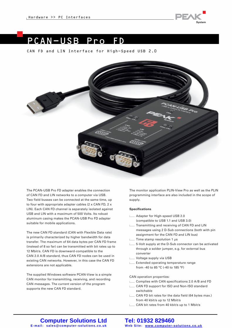
PCAN-USB Pro FD
Hardware >> PC Interfaces
CAN FD and LIN Interface for High-Speed USB 2.0
www.peak-system.com Products 2015
The monitor application PLIN-View Pro as well as the PLIN
programming interface are also included in the scope of
supply.
Specifications
Adapter for High-speed USB 2.0
(compatible to USB 1.1 and USB 3.0)
Transmitting and receiving of CAN FD and LIN
messages using 2 D-Sub connections (both with pin
assignment for the CAN FD and LIN bus)
Time stamp resolution 1 µs
5-Volt supply at the D-Sub connector can be activated
through a solder jumper, e.g. for external bus
converter
Voltage supply via USB
Extended operating temperature range
from -40 to 85 °C (-40 to 185 °F)
CAN operation properties:
Complies with CAN specifications 2.0 A/B and FD
CAN FD support for ISO and Non-ISO standard
switchable
CAN FD bit rates for the data field (64 bytes max.)
from 40 kbit/s up to 12 Mbit/s
CAN bit rates from 40 kbit/s up to 1 Mbit/s
The PCAN-USB Pro FD adapter enables the connection
of CAN FD and LIN networks to a computer via USB.
Two field busses can be connected at the same time, up
to four with appropriate adapter cables (2 x CAN FD, 2 x
LIN). Each CAN FD channel is separately isolated against
USB and LIN with a maximum of 500 Volts. Its robust
aluminum casing makes the PCAN-USB Pro FD adapter
suitable for mobile applications.
The new CAN FD standard (CAN with Flexible Data rate)
is primarily characterized by higher bandwidth for data
transfer. The maximum of 64 data bytes per CAN FD frame
(instead of 8 so far) can be transmitted with bit rates up to
12 Mbit/s. CAN FD is downward-compatible to the
CAN 2.0 A/B standard, thus CAN FD nodes can be used in
existing CAN networks. However, in this case the CAN FD
extensions are not applicable.
The supplied Windows software PCAN-View is a simple
CAN monitor for transmitting, receiving, and recording
CAN messages. The current version of the program
supports the new CAN FD standard.
12
Computer Solutions LtdE-mai l : sales@computer - solut ions. co.uk
Tel: 01932 829460W eb Si te: www.computer -solut ions.co.uk

Hardware >> PC Interfaces
www.peak-system.com Products 2015
Designation Part No.
PCAN-USB Pro FD IPEH-004061
Scope of supply
PCAN-USB Pro FD in aluminum casing
CAN FD interface drivers for Windows 8.1, 7, Vista
and Linux (32/64 bit)
LIN interface drivers for Windows 8.1, 7, Vista
(32/64 bit)
PCAN-View CAN monitor for Windows
(details on page 85)
PLIN-View Pro LIN monitor for Windows
(details on page 86)
PCAN-Basic programming interface consisting of
an interface DLL, examples, and header files for
all common programming languages
(details on page 76)
PLIN-API programming interface consisting of an
interface DLL, an example, and header files for all
common programming languages
Manual in PDF format
Please note: The PCAN-USB Pro FD can be used
alternatively for the PCAN-USB Pro, because this CAN
interface is no longer manufactured!
The PCAN-USB Pro FD behaves identically concerning
the CAN and LIN functionality.
Ordering information
D-Sub Pin Pin assignment1 Not connected / optional +5V2 CAN-L3 CAN-GND4 LIN5 LIN-GND6 LIN-GND7 CAN-H8 Not connected9 VBAT
FPGA implementation of the CAN FD controller
NXP TJA1044GT CAN transceiver
Each CAN FD channel is separately opto-decoupled
against USB and LIN up to 500 V
CAN termination can be activated through a
solder jumper
Measurement of bus load including error frames and
overload frames on the physical bus
Induced error generation for incoming and outgoing
CAN messages
LIN operation properties:
Bit rates from 1 kbit/s up to 20 kbit/s
TJA1021/20 LIN transceiver
Both LIN channels (common ground) are opto-
decoupled against USB and CAN FD
Can be used as a LIN master or slave
(1 ms master task resolution)
Automatic bit rate, frame length, and checksum type
recognition
Autonomous scheduler with support for
unconditional, event, and sporadic frames
Hardware can work through a schedule table
(up to 8 schedule tables can be configured with a total
of 256 slots)
13
Computer Solutions LtdE-mai l : sales@computer - solut ions. co.uk
Tel: 01932 829460W eb Si te: www.computer -solut ions.co.uk

Using CAN
PEAK CAN ControllersThe Peak range of CAN interfaces provides simple and cost effective connections between PCsand CAN-networks and includes routers, extenders and adapters to the many CAN variants.
PCAN interfaces support both 11 bit ID and 29 bit ID CAN specifications with a maximum speedof 1Mbaud. They use the SJA1000 CAN-controller and the 82C251 driver. The CAN-bus connection isvia a 9-pin SUB-D plug, whose pin assignments conform to the CiA recommendation. No termination isincluded in the interfaces. Optoisolated versions are available if required and most interfaces can besupplied with one or two ports.
Drivers and supporting DLL’s are included to allowoperation under XP, Vista, Windows 7 and Linux in32 and 64* bit modes. CE6.x support* for ARMand x86 is also available. (* most interfaces).Language support is provided for C++, C#,C++/CLR, Delphi, VB.NET, Java and Python 2.6.
A Windows package PCAN-View is included withall interfaces to allow the user to view messages onthe CAN bus. All data is displayed in Hex andmessages are timed and counted. A trace bufferallows messages to be recorded and saved to disk.Errors such as over-run and baud rate problemsare reported. Messages can be user created and
then sent as one-shot, repeating periodically or in response to a remote request (RTR).
Industrial I/O ModulesThese Industrial I/O modules are available in a number of usefulconfigurations including signal conditioning and termination in an industrialcase. Up to 8 10 bit analogue inputs, 4 PWM/frequency outputs (to 20KHz)and 8 digital ins and outs are available. At 51 x 60 x 20mm, they are suitablefor a wide variety of applications. The electrical connections provide snap-intermination; with a screw connection as an option. A windows package isprovided so that the user can set message ID and data layouts andconversion constants as well as setting report rates or reporting on change.
CAN Open firmware is also available if required.
USB
PC/104
PCMCIA PARALLEL PORT
ISA
PCI
Computer Solutions LtdE-mai l : sales@computer - solut ions. co.uk
Tel: 01932 829460W eb Si te: www.computer -solut ions.co.uk

PCAN-ExplorerThis tool can be used as an advanced CAN bus
traffic monitor. It provides the following features:
Message identifiers can be given names avoiding
having to remember each messages HEX value.
Message data can be displayed in a wide range
of formats including text, hex, signed, unsigned
and floating point.
An extensive conditional macro language allows
complex tests and simulations to be performed.
Optional packages provide sophisticated
graphing, CANdb data exchange, a visual GUI to
control and display CAN data collection and a full
J1939 symbol database simplifying control of
ECU’s.
PCAN-FMS ToolkitA special software package is available to support FMS and Bus-FMS standards. It logs andtranslates the CAN messages in real time providing the user with a “Dashboard display”. The log canbe replayed to a CAN bus or values can be set manually from a convenient Windows display forsystem simulation.
Data Acquisition SystemsPeak have a growing range of units designed to suite a variety of data acquisition requirements such asmulti Thermocouple, A/D and D/A conversions and digital I/O. As well as data logging and mobile GPRSlinks there are also CAN Routers and filters. Some have full C programmability others only need simplewindows configuration.
CAN MicroMod BoardsA flexible, small format, Analogue and Digital I/O board with a CAN-Businterface.
The PCAN-MicroMod board can be plugged into an application to providecontrol and monitoring services via the CAN-Bus. It provides the following
8 analogue inputs, 10-bits resolution, Vref 5 V
8 digital inputs & 8 digital outputs
4 PWM / frequency outputs, with a range 1 Hz-20 kHz
The integrated firmware provides simple configuration of the target system via a Windows utility program,the configuration data being sent to the board via CAN. No embedded programming skills are requiredto set up a system. Up to 32 PCAN-MicroMod boards can be put onto a single CAN network.
An optional evaluation board simplifies development of user designed carrier boards and also makes theMicroMod an ideal CAN evaluation tool.
Call or email us with your requirements.
Computer Solutions LtdE-mai l : sales@computer - solut ions. co.uk
Tel: 01932 829460W eb Si te: www.computer -solut ions.co.uk

59
PCAN-Explorer 5 Comprehensive CAN Monitor for Windows
Software >> PCAN-Explorer & Add-ins
www.peak-system.com Products 2011 / 2012
PCAN-Explorer is a universal tool for monitoring data
traffic on a CAN network. For easy and clear allocation
of the individual messages, these can be identified as
so-called symbols. The integrated VBScript support
allows the creation of macros to automate complex
tasks. The integrated data logger means that the data
traffic of a bus can be recorded, analyzed, and stored.
PCAN-Explorer is designed as automation server and
can therefore be remote controlled through scripts.
Features
All files and elements can be managed and saved
in projects
Project components such as CAN connections,
symbol files and macros are clearly displayed and
laid out in the project browser
The new start page allows fast access to the most
recently opened projects or files
Simultaneous connections with multiple networks/
CAN interfaces of the same hardware type
Connection window with an overview of all
connections, complete with status, error counters,
bus load, etc.
All parameters of all elements in the user interface
can be examined using a property window and
edited if necessary.
Multiple flexible filters can be configured and, for
example, assigned to the transmit/receive window
or the various different tracers
Tabs to switch between the different Windows
Flexible arrangement of the user interface using
the dockable windows
User-defined column display and arrangement in
transmit/receive window
J1939 support with the relevant add-in
Display of received messages showing the ID,
length, data bytes, number of messages received
and receiving interval
Simultaneous hexadecimal and symbolic
representation of the details
Display of remote frames, status reports of the
CAN controller and, as option, CAN-bus error
frames also
Logging of time-outs
Sending of messages at fixed intervals of time,
manually or as reply to remote frames
Computer Solutions LtdE-mai l : sales@computer - solut ions. co.uk
Tel: 01932 829460W eb Si te: www.computer -solut ions.co.uk

60
Software >> PCAN-Explorer & Add-ins
www.peak-system.com Products 2011 / 2012
Messages can be created as send lists, stored and
loaded as desired, in order to e. g. emulate CAN
nodes
Periodical sending with up to 1 ms precision
Easy creation of symbol files and macros using the
integrated text editor with syntax highlighting
User-friendly real-time monitoring of several
signals via the watch window
Extensive improvements to user guidance and
interface compared to PCAN-Explorer version 4
User interface language can be switched
(German/English)
Simple integration of external tools
Integration of Add-Ins to upgrade functionality
Properties of the integrated, configurable PCAN-
Explorer data logger:
Operation of multiple tracers at the same time
Variable buffer size
Optional linear buffer or circular buffer
Representation of the logged messages with time
stamp, type, ID, length and data bytes
Logging of errors that have occurred is possible
Flexible storage possibility for the logged data in
text form for importing into Excel or similar
Filtering of the messages for logging through
symbol definitions
Subsequent examination of the logged data in the
buffer via different symbol files
Computer Solutions LtdE-mai l : sales@computer - solut ions. co.uk
Tel: 01932 829460W eb Si te: www.computer -solut ions.co.uk

61
Function upgrade of the PCAN-Explorer with the
integrated VBScript language:
Creation of macros in VBScript with the integrated
text editor
Access with macros and scripts to almost all
program elements via the PCAN-Explorer object
model
Ideal for creating test tools to implement or
develop CAN systems
Examples: sending of e-mails when a temperature
is exceeded, starting of a test tool when a
particular message is received, opening of an
Excel sheet when an event occurs and saving of
data in the individual cells
Assignment of function keys with individual send
messages or macros
VBS scripts run in the background even without
the PCAN-Explorer interface
www.peak-system.com Products 2011 / 2012
Software >> PCAN-Explorer & Add-ins
Designation Art. No.
PCAN-Explorer 5 IPES-005028
Scope of supply
PCAN-Explorer installation CD including
PCAN-Explorer Line Writer Add-in
PCAN Symbol Editor for Windows
(details on page 62)
Documentation in HTML help format
System requirements
Windows 7/Vista/XP (32/64-bit)
At least 512 MB RAM and 1 GHz CPU
Ordering information
Computer Solutions LtdE-mai l : sales@computer - solut ions. co.uk
Tel: 01932 829460W eb Si te: www.computer -solut ions.co.uk

63
Software >> PCAN-Explorer & Add-ins
Optional Function Upgrades for PCAN-Explorer
PCAN-Explorer Add-ins
Designation Art. No.
J1939 Add-in IPES-005089
Scope of supply
J1939 Add-in software
Documentation in HTML help format
System requirements
PCAN-Explorer 5
Windows 7/Vista/XP (32/64-bit)
At least 512 MB RAM and 1 GHz CPU
Ordering informationJ1939 Add-in
The SAE J1939 network protocol describes
communication on a CAN bus in utility vehicles for
the transmission of diagnostics data and control
information. It contains a complete network definition
using 29-bit CAN-IDs (CAN 2.0B Extended Frame).
The J1939 add-in for PCAN-Explorer 5 supports all
definitions established by the standard’s parameter
groups and provides a simple means of accessing the
parameters. A complete database of all the definitions
and the parameters contained is also supplied.
Features
Support for all functions of the SAE J1939 network
protocol
CAN messages can be sent in broadcast form or
targeted to individual control units (ECUs)
Addressing of up to 254 ECUs
Supports multi-packet messages
www.peak-system.com Products 2011 / 2012 Computer Solutions LtdE-mai l : sales@computer - solut ions. co.uk
Tel: 01932 829460W eb Si te: www.computer -solut ions.co.uk

64
PCAN-Explorer Add-insOptional Function Upgrades for PCAN-Explorer
Software >> PCAN-Explorer & Add-ins
Designation Art. No.
Plotter Add-in 2 IPES-005087
Scope of supply
PCAN-Plotter Add-in software
System requirements
PCAN-Explorer 5
Windows 7/Vista/XP (32/64-bit)
At least 512 MB RAM and 1 GHz CPU
Ordering information
Plotter Add-in 2
The plotter allows the graphical representation of CAN
data using any number of channels.
Features
Real-time display
Unlimited number of channels
Unlimited number of Y-axes
X-axis and Y-axes can be zoomed and scrolled
quite freely, even during recording
Labelling of time axis with absolute or relative
time stamps
Facility for automatic adaptation of axes to plots
Reversible Y-axes
Logarithmic scales
Cursor display for plot measurement
Export to EMF-, PNG-, BMP-, JPEG graphical
formats
Data import from the PCAN-Explorer Tracer
www.peak-system.com Products 2011 / 2012
Representation of limiting values and value ranges
Comprehensive formatting options for
representing the curves, axes and the plotter
layout
Computer Solutions LtdE-mai l : sales@computer - solut ions. co.uk
Tel: 01932 829460W eb Si te: www.computer -solut ions.co.uk

65
PCAN-Explorer Add-insOptional Function Upgrades for PCAN-Explorer
Software >> PCAN-Explorer & Add-ins
Designation Art. No.
CANdb Import Add-in 3 IPES-005086
Scope of supply
CANdb Import Add-in software
Documentation in HTML help format
System requirements
PCAN-Explorer 5
Windows 7/Vista/XP (32/64-bit)
At least 512 MB RAM and 1 GHz CPU
Ordering information
www.peak-system.com Products 2011 / 2012
CANdb Import Add-in 3
The CANdb format is a common data description
format for CAN bus information in the car industry.
CANdb Import allows the import of CANdb files. This
is a useful function for all those who do not want to
manually transcribe their database into the
PCAN-Explorer symbol file format.
Features
Opening of CANdb files (.dbc)
Selecting of the messages for importing in a
CANdb file
Saves data using the project administration
function in PCAN-Explorer
Storing in the PCAN-Explorer symbol file format
Computer Solutions LtdE-mai l : sales@computer - solut ions. co.uk
Tel: 01932 829460W eb Si te: www.computer -solut ions.co.uk

66
PCAN-Explorer Add-insOptional Function Upgrades for PCAN-Explorer
Software >> PCAN-Explorer & Add-ins
www.peak-system.com Products 2011 / 2012
Instruments Panel Add-in 3
The Instruments Panel Add-in allows the graphical
representation of digital and analog signals using
different display instruments. The integrated input
options and controllers mean that signals can also be
produced on the CAN bus, allowing easy simulation of
complex CAN applications.
Free positioning of the instruments using
drag & drop, or numerical inputs for spot-on
positioning
Loading and storing of complete panel
configurations
Features
Representation of analog and digital signals from
received CAN messages using different display
instruments
In addition to potentiometers, switches, and
sliding controllers input fields can be used to
generate CAN messages
Selection and configuration of multiple elements
at the same time
Extensive configuration of the properties of one or
more elements using the new property window
The new Instruments Panel object model enables
complete automation using COM and scripts
Representation of different scenes on the same
panel during running time
Signal-dependent display of image lists and
scenes
Designation Art. No.
Instruments Panel Add-in 3 IPES-005088
Scope of supply
Instruments Panel Add-in software
Documentation in HTML help format
System requirements
PCAN-Explorer 5
Windows 7/Vista/XP (32/64-bit)
At least 512 MB RAM and 1 GHz CPU
Ordering information
Computer Solutions LtdE-mai l : sales@computer - solut ions. co.uk
Tel: 01932 829460W eb Si te: www.computer -solut ions.co.uk

58
PCAN-TraceComprehensive Data Logger for CAN Messages
Software >> Application Software
Designation Art. No.
PCAN-Trace IPES-002027
Scope of supply
PCAN-Trace installation CD
(in English)
Documentation in HTML help format
System requirements
Windows 7/Vista/XP (32-bit)
At least 512 MB RAM and 1 GHz CPU
Ordering information
The PCAN-Trace program is a data logger for up to
9,999,000 CAN messages. It enables CAN messages
to be quickly recorded, saved, and even played back
on the CAN bus. The program displays the number
of received messages, and identifies the types of the
messages (data frame, error frame, RTR frame).
CAN messages can be recorded or replayed in linear or
ring buffer mode. PCAN-Trace also provides an option
to play back CAN messages in single step mode.
You can also simplify analysis and tracing by setting
playback mode breakpoints.
www.peak-system.com Products 2011 / 2012
Features
Log facility for up to 9,999,000 CAN messages
Choice of linear buffer or ring buffer (in receive
and playback mode)
Displays number and type of received
CAN messages
Adjustable message filter
Support for 11-bit and 29-bit IDs
Facility to play back CAN messages that have
been recorded using PCAN-Explorer,
even in single-step mode
Breakpoints can be used in playback mode
Integrated online help
Received data can also be viewed in a text editor
Computer Solutions LtdE-mai l : sales@computer - solut ions. co.uk
Tel: 01932 829460W eb Si te: www.computer -solut ions.co.uk