CAN Data Concentrator Module - Horner Automation
22
User Manual for the HE693CDC300 CAN Data Concentrator Module Fourth Edition 24 November 2003 MAN0050-04
Transcript of CAN Data Concentrator Module - Horner Automation

User Manual for the HE693CDC300
CAN Data Concentrator Module
Fourth Edition
24 November 2003
MAN0050-04


PREFACE 24 NOV 2003 PAGE 3
PREFACE This manual explains how to use the Horner APG CAN Data Concentrator Module for use in Controller Area Networks. Copyright (C) 2003, Horner APG, LLC., 640 North Sherman Drive, Indianapolis, Indiana 46201-3899. All rights reserved. No part of this publication may be reproduced, transmitted, transcribed, stored in a retrieval system, or translated into any language or computer language, in any form by any means, electronic, mechanical, magnetic, optical, chemical, manual or otherwise, without the prior agreement and written permission of Horner APG, LLC. All software described in this document or media is also copyrighted material subject to the terms and conditions of the Horner APG Software License Agreement. Information in this document is subject to change without notice and does not represent a commitment on the part of Horner APG, LLC. LogicMaster 90 and Series 90-30 PLC are trademarks of GE Fanuc.

PAGE 4 24 NOV 2003 PREFACE
LIMITED WARRANTY AND LIMITATION OF LIABILITY Horner APG, LLC. ("HE-APG") warrants to the original purchaser that the CAN Data Concentrator Module manufactured by HE-APG is free from defects in material and workmanship under normal use and service. The obligation of HE-APG under this warranty shall be limited to the repair or exchange of any part or parts which may prove defective under normal use and service within two (2) years from the date of manufacture or eighteen (18) months from the date of installation by the original purchaser whichever occurs first, such defect to be disclosed to the satisfaction of HE-APG after examination by HE-APG of the allegedly defective part or parts. THIS WARRANTY IS EXPRESSLY IN LIEU OF ALL OTHER WARRANTIES EXPRESSED OR IMPLIED INCLUDING THE WARRANTIES OF MERCHANTABILITY AND FITNESS FOR USE AND OF ALL OTHER OBLIGATIONS OR LIABILITIES AND HE-APG NEITHER ASSUMES, NOR AUTHORIZES ANY OTHER PERSON TO ASSUME FOR HE-APG, ANY OTHER LIABILITY IN CONNECTION WITH THE SALE OF THIS CAN Data Concentrator Module. THIS WARRANTY SHALL NOT APPLY TO THIS MODULE OR ANY PART THEREOF WHICH HAS BEEN SUBJECT TO ACCIDENT, NEGLIGENCE, ALTERATION, ABUSE, OR MISUSE. HE-APG MAKES NO WARRANTY WHATSOEVER IN RESPECT TO ACCESSORIES OR PARTS NOT SUPPLIED BY HE-APG. THE TERM "ORIGINAL PURCHASER", AS USED IN THIS WARRANTY, SHALL BE DEEMED TO MEAN THAT PERSON FOR WHOM THE CAN Data Concentrator Module IS ORIGINALLY INSTALLED. THIS WARRANTY SHALL APPLY ONLY WITHIN THE BOUNDARIES OF THE CONTINENTAL UNITED STATES. In no event, whether as a result of breach of contract, warranty, tort (including negligence) or otherwise, shall HE-APG or its suppliers be liable of any special, consequential, incidental or penal damages including, but not limited to, loss of profit or revenues, loss of use of the products or any associated equipment, damage to associated equipment, cost of capital, cost of substitute products, facilities, services or replacement power, down time costs, or claims of original purchaser's customers for such damages. To obtain warranty service, return the product to your distributor with a description of the problem, proof of purchase, post paid, insured and in a suitable package. ABOUT PROGRAMMING EXAMPLES Any example programs and program segments in this manual or provided on accompanying diskettes are included solely for illustrative purposes. Due to the many variables and requirements associated with any particular installation, Horner APG cannot assume responsibility or liability for actual use based on the examples and diagrams. It is the sole responsibility of the system designer utilizing the CAN Data Concentrator Module to appropriately design the end system, to appropriately integrate the CAN Data Concentrator Module and to make safety provisions for the end equipment as is usual and customary in industrial applications as defined in any codes or standards which apply. Note: The programming examples shown in this manual are for
illustrative purposes only. Proper machine operation is the sole responsibility of the system integrator.

PREFACE 24 NOV 2003 PAGE 5
REVISIONS TO THIS MANUAL 1. Revised Section 3.1. 2. Revised Table 3.1 (%R41, %R49, and %R50). 3. Added new LED Sections 4.2 and Section 4.3.

PAGE 6 24 NOV 2003 PREFACE

PREFACE 24 NOV 2003 PAGE 7
TABLE OF CONTENTS PREFACE ................................................................................................................................................... 3 LIMITED WARRANTY AND LIMITATION OF LIABILITY........................................................................... 4 ABOUT PROGRAMMING EXAMPLES ...................................................................................................... 4 TABLE OF CONTENTS.............................................................................................................................. 7 CHAPTER 1: INTRODUCTION ................................................................................................................. 9
1.1 General ......................................................................................................................................... 9 1.3 Technical Assistance...................................................................................................................... 10
CHAPTER 2: INSTALLATION .................................................................................................................. 11 2.1 PLC Software Configuration....................................................................................................... 11
CHAPTER 3: PLC REGISTER MAP......................................................................................................... 13 3.1 General ....................................................................................................................................... 13
CHAPTER 4: WIRING............................................................................................................................... 17 4.1 CAN Wiring and Connector ........................................................................................................ 17
4.1.1 CAN Wiring Rules ............................................................................................................... 18 CHAPTER 5: LEDs .................................................................................................................................. 21
5.1 CDC300 LEDs ............................................................................................................................ 21 5.2 Additional LEDs (SER300 and TIM100)..................................................................................... 21

PAGE 8 24 NOV 2003 PREFACE
NOTES

CHAPTER 1: INTRODUCTION 24 NOV 2003 PAGE 9
CHAPTER 1: INTRODUCTION 1.1 General The HE693CDC300 is a CAN Data Concentrator (CDC300) I/O Module for the GE Fanuc Series 90-30 PLC. The CAN Data Concentrator receives data containing logged events from a Sequence of Events Recorder (HE693SER300) over the Control Area Network (CAN). A typical setup using the HE693CDC300 is described as follows: The HE693SER300 Sequence of Events Recorder Module (SER300) time-stamps and records events with a time resolution of one millisecond and resides in the CPU slot of a GE Fanuc 90-30 rack IC693CHS397 or IC693CHS391) Up to eight Sequence of Event Recorders (SERs) can be put on the network at one time. The SER300 module resides in the CPU slot of a Series 90-30 PLC rack and scans GE Fanuc Digital Input Modules located on the same rack. If any input connected to an input module changes state, the event is time-stamped and recorded in an event table internal to the SER. The event table and digital input data are made available to the CDC300 CAN Data Concentrator I/O Module via the CAN bus. In addition, GE Fanuc Digital Output Modules (located in a Series 90-30 rack with an SER300 in the CPU slot) can be controlled via CAN messages that are sent from a CDC300 module to the SER300 module. See the following diagram for a complete overview. Note: For additional information, consult the HE693SER300 user manual.
Table 1.1 - Specifications Required Power (Steady State) 120mA. @ 5VDC Relative Humidity 5 to 95% Non-condensing
Required Power (Inrush)
190mA. @ 5VDC for 3.1mS.
Operating Temperature
0° to 60° Celsius

PAGE 10 24 NOV 2003 CHAPTER 1: INTRODUCTION
1.3 Technical Assistance For assistance or to check for periodic manual updates, contact the following resources. North America: (317) 916-4274 www.heapg.com Europe: (+) 353-21-4321-266 www.horner-apg.com
1. GE Fanuc Input Modulesreceive inputs from various sensory equipment, etc.
2. The SER300s scan up to 256 input points of the I\O modules to look for events and to time stamp them. The SER300 notifies the CDC via a Fast Message format. When the CDC300 responds with instructions, the SER300 acknowledges the commands via a SMART Message format . The SER300 also provides updates to the Digital Output Modules if directed.
3. Upon detecting an event, the SER300 sends a Fast Message to the CDC300 to indicate that an event has occurred, etc. The CDC, then, notifies the GE Fanuc CPU. When the GE Fanuc CPU responds with instructions, the CDC300 sends them via a SMART Message to the SER300.
4. The GE Fanuc CPU sends instructions to the CDC300 indicating what it wants done such as obtaining an event or sending data to the GE Fanuc Output Modules.
CAN Bus
6. The GPS Time Server (TIM100) provides a 100 µsec. reference to keep the SER300s synchronized. The reference is sent on to the CAN Bus every one second.
HE500TIM100 GPS TIME SERVER
SER300
SER300
CDC300
IN IN OUT
IN IN OUT
GE FANUC CPU
GE FANUC I/O MODULES
SATELLITES5. Digital Output Modules are updated by the SER300 (if commanded by the GE Fanuc CPU) to allow broadcasting to remote equipment.
Figure 1.1 - Overview

CHAPTER 2: INSTALLATION 24 NOV 2003 PAGE 11
CHAPTER 2: INSTALLATION 2.1 PLC Software Configuration Before the HE693CDC300 Module may be used, it must be configured by using PLC Configuration Software or with a Hand Held Programmer (HHP). 1. Open the PLC Configuration Software and select the 90-30 Configuration Package
(Alt-F3 will select the 90-30, and F2 will select the Configuration Utility). 2. Choose a Program Folder or create a new one. 3. Press F1 to configure the I/O. 4. Select the slot that contains the CDC and press F8 for “Other”. Press F3 to select
“Foreign” for the module type, and press the Enter key. The following screen should appear.
Figure 2.1 – PLC Configuration Screen
PAGE 12 24 NOV 2003 CHAPTER 2: INSTALLATION
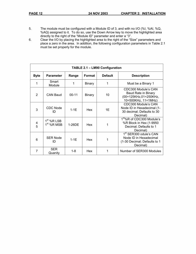
5. The module must be configured with a Module ID of 3, and with no I/O (%I, %AI, %Q,
%AQ) assigned to it. To do so, use the Down Arrow key to move the highlighted area directly to the right of the “Module ID” parameter and enter a “3”.
6. Clear the I/O by placing the highlighted area to the right of the “Size” parameters and place a zero in the area. In addition, the following configuration parameters in Table 2.1 must be set properly for the module.
TABLE 2.1 – LM90 Configuration
Byte Parameter Range Format Default Description
1 Smart Module 1 Binary 1 Must be a Binary 1
2 CAN Baud 00-11 Binary 10
CDC300 Module’s CAN Baud Rate in Binary
(00=125KHz,01=250KHz, 10=500KHz, 11=1MHz)
3 CDC Node ID 1-1E Hex 1E
CDC300 Module’s CAN Node ID in Hexadecimal (1-30 decimal; Defaults to 30
Decimal)
4 5
1st %R LSB 1st %R MSB
1-26DE Hex 1
1st%R of CDC300 Module’s %R Block in Hex (1-9950
Decimal; Defaults to 1 Decimal)
6 SER Node ID 1-1E Hex 1
1st SER300 odule’s CAN Node ID in Hexadecimal
(1-30 Decimal; Defaults to 1 Decimal)
7 SER Quanity 1-8 Hex 1 Number of SER300 Modules

CHAPTER 3: PLC REGISTER 24 NOV 2003 PAGE 13
CHAPTER 3: PLC REGISTER MAP 3.1 General The HE693SER300 modules make their data available to the HE693CDC300 module via the CAN bus. The HE693CDC300 then uses backplane mail to map this data into a block of %R PLC Registers. The 1st %R Register number of this block should be configured into the 1st %R configuration parameter described in Table 2-1. The size of the %R block is dependent on the number of HE693SER300’s on the network. %R Block Size = SER Quantity * 50 The SER Quantity configuration parameter is the number of HE693SER300 Modules assigned to the HE693CDC300. The assigned HE693SER300 Modules must have consecutive CAN Node IDs starting with the SER Node ID configuration parameter value. Within the HE693CDC300 Module’s block of %R PLC Registers, a 50-word block of %R PLC Registers is mapped to each of the assigned HE693SER300 Modules. The first 50 %R PLC Registers are mapped to the HE693SER300 Module with a matching CAN Node ID to the SER Node ID configuration parameter. The second 50 %R PLC Registers are mapped to the HE693SER300 Module with the next higher CAN Node ID, and so on. Table 3.1 shows how data is mapped into each of the 50-Word %R blocks and Items a –h describe functions. (Items a – h are described following Table 3.1.)

PAGE 14 24 NOV 2003 CHAPTER 3: PLC REGISTER
Table 3.1 – PLC Registers
NOTE: Refer to Table 3.2 for the item number indicated in the Register Column. Register(s) Value or Range Description See item a.
%R1
%R2 LSB %R2 MSB %R3 LSB %R3 MSB %R4 LSB %R4 MSB
0000-0999 00-60 00-59 00-23 01-31 01-12 00-99
New Event Millisecond in packed BCD New Event Seconds in packed BCD New Event Minute in packed BCD New Event Hour in packed BCD New Event Date in packed BCD
New Event Month in packed BCD New Event Year in packed BCD
See Item b.
%R5-R20 0 or 1 for each bit New Event Input Data in Binary (up to 256 digital input bits)
See item c.
%R21-R24 Same as R1-R4 Current Time in BCD (Update time set optional)
See item d.
%R25-R40 Same as R5-R20 Current Input Data in Binary (Updated on change of state)
See item e.
%R41
HE693SER300 Module Command Register, Bit 0 = Get Event, Bit 1 = Clear Events, Bit 2 = Enable Recording, Bit 3 = Get Status, Bit 4 = Update Status,
Bit 5 = Update Outputs, Bit 6 = Send Mask. See item e.
- %R42
Bit-Mapped
HE693SER300 Module Response Register Same encoding as R41
See item f.
%R43 Bit-Mapped
HE693SER300 Module Status Register Bit 0 = Event(s) Available, Bit 1 = IRIGB OK, Bit 2 =
Module Ok, Bit 3 = Buffer Full See item g.
%R44
0000-9999 HE693SER300Module Firmware Version Number in BCD
See item h.
%R45-%R48 0 or 1 for each bit New Output Data in Binary (up to 64 digital output bits)
%R49 0 to 31 Input Mask Word Index %R50 0 to FFFFh Input Mask
Refering to Table 3.1, if two or more nodes (SER racks) are used, the rack with the lowest CAN Node ID uses %R1-%R50, The next highest uses %R51-%R100, The next %R101-%R150, etc. The input mask allows inputs to be selectivly disable on the SER for change of state detection. This is usful to temporarly ignore an input that may be oscilating and causing large numbers of events to be recorded. To send the mask first set the “Input Mask Word Index”. This number selects which 16-bit block of inputs to mask. For example, for the first 16 inputs set the index to 0, for inputs 17 to 32 set the index to 1, for inputs 33 to 48 set the index to 2, and so on. Next set the Input mask. This defines which of the 16 inputs to ignore. Each bit in the register represents an input, with the least significant bit representing the first input. If the bit is set, the input is ignored, if the bit is cleared, the input functions normally. For example to mask the 3rd and 8th inputs set the input mask to 00000000 10000100 (binary) or 0084 (hex). The mask in the SER is not retentive and must be sent every time the SER is power cycled. Inputs that are masked are still recorded in the event recorder, but a masked input can not cause an event to be recorded.

CHAPTER 3: PLC REGISTER 24 NOV 2003 PAGE 15
Table 3.2 – Types of PLC Registers NOTE: This table is used inconjuction with Table 3.1.
Item r Description a. Event Time Stamp Registers (R1...R4)
These registers contain the time stamp associated with the event input data stored in R5...R20. Note that the time data is in packed Binary Coded Decimal (BCD[4 decimal digits per register]).
b. Event Input Data Registers (R5...R20)
The registers contain the state of the HE693SER300 module’s digital input data at the instant of the event.
c. Current Time Registers (R21...R24)
The registers contain the current time in the same format as the event time stamp (R1...R4). Note that the current time is updated once per second, so the milliseconds register (R21) will always be near zero. Also notice that the seconds value (LSB of R2) can be 60 if a leap second insertion occurs.
d. Current Input Data Registers (R25...R40)
The registers contain the current state of the HE693SER300 Module’s Digital Input Data and is updated each time one or more inputs change state.
e. Command/Response Registers (R41...R42)
The R41 and R42 registers provide command/response handshaking to control the HE693SER300 module which corresponds to this 50-Word block. With this command/response handshaking, the HE693SER300 may be instructed to send its next stored event, clear all its stored events, enable/disable event recording, send its status register and/or update its digital outputs. The following sequence describes the command/response handshaking:
1. The PLC modifies one or more command bits in R41.
2. The HE693CDC300 module executes the command(s) implied by the modified bits in R41.
3. The HE693CDC300 module modifies the response bits in R42 to match the command bits just serviced in R41.
The Enable Recording bits (bit 2) in R41 and R42 is be a value of “1” (enabled) at power-up.
f. Status Register (R43)
The register contains HE693SER300 module status information. The events available bit will be a “1” if the HE693SER300 module has any events stored. The IRIG-B OK bit will be a “1” if the HE693SER300 Module has established time sync with the GPS receiver. The “Module OK” bit will be a “1” if the HE693SER300 is communicating properly. The “Buffer Full” bit will be a “1” if the HE693SER300 has a full event buffer.
g. Version Number Register (R44)
The register contains the firmware version number of the code which was last downloaded into the HE693SER300. Note that the version number is stored in packed BCD format (4 decimal digits) with an implied decimal point between the 2nd and 3rd digits.
h. New Output Data Registers (R45...R48)
The registers should be loaded with the new desired state of the HE693SER300 module’s digital output data. This data will be sent to the HE693SER300 module when an “Update Outputs command” is executed.

PAGE 16 24 NOV 2003 CHAPTER 3: PLC REGISTER
NOTES
CHAPTER 4 WIRING 24 NOV 2003 PAGE 17
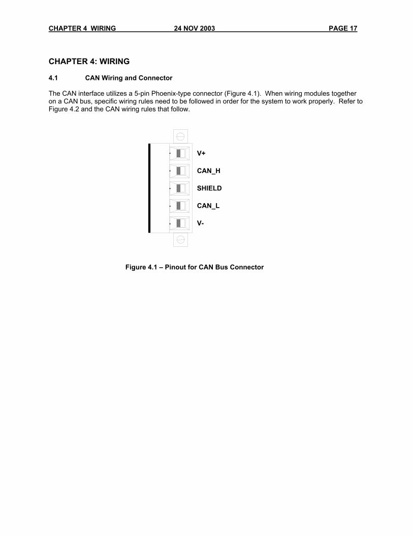
CHAPTER 4: WIRING 4.1 CAN Wiring and Connector The CAN interface utilizes a 5-pin Phoenix-type connector (Figure 4.1). When wiring modules together on a CAN bus, specific wiring rules need to be followed in order for the system to work properly. Refer to Figure 4.2 and the CAN wiring rules that follow.
V+ CAN_H SHIELD CAN_L V-
Figure 4.1 – Pinout for CAN Bus Connector
PAGE 18 24 NOV 2003 CHAPTER 4: WIRING
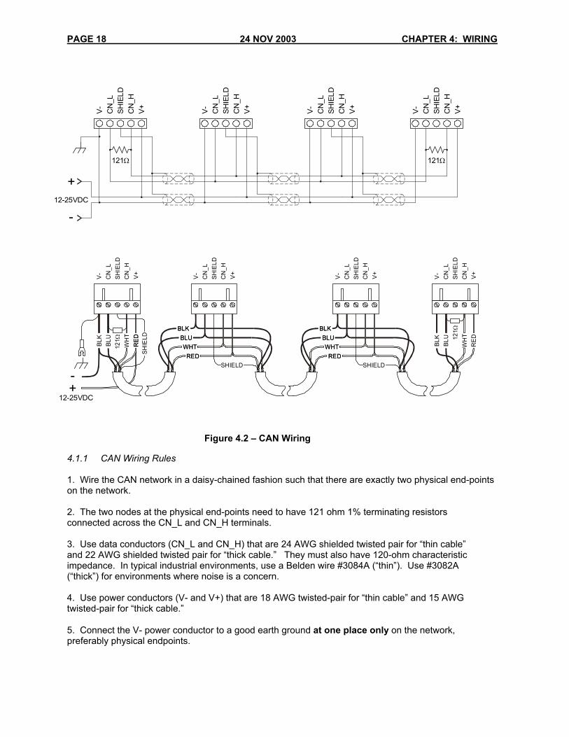
4.1.1 CAN Wiring Rules 1. Wire the CAN network in a daisy-chained fashion such that there are exactly two physical end-points on the network. 2. The two nodes at the physical end-points need to have 121 ohm 1% terminating resistors connected across the CN_L and CN_H terminals. 3. Use data conductors (CN_L and CN_H) that are 24 AWG shielded twisted pair for “thin cable” and 22 AWG shielded twisted pair for “thick cable.” They must also have 120-ohm characteristic impedance. In typical industrial environments, use a Belden wire #3084A (“thin”). Use #3082A (“thick”) for environments where noise is a concern. 4. Use power conductors (V- and V+) that are 18 AWG twisted-pair for “thin cable” and 15 AWG twisted-pair for “thick cable.” 5. Connect the V- power conductor to a good earth ground at one place only on the network, preferably physical endpoints.
Figure 4.2 – CAN Wiring
121Ω
V-
CN
_LSH
IELD
CN
_HV
+
V-
CN
_LSH
IELD
CN
_HV
+
V-
CN
_LSH
IELD
CN
_HV
+
121Ω
V-
CN
_LSH
IELD
CN
_HV
+
12-25VDC
+
-
REDWHT
SHIELD
BLUBLK
RE
DSH
IELD
REDWHT
BLUBLK
V+CN
_LV
-
SHIE
LD12
1 ΩC
N_H
V+CN
_LV
-
SHIE
LDC
N_H
RED
WH
T
BLU
BLK 12
1Ω
V+CN
_LV
-
SHIE
LDC
N_H
RED
WH
T
BLU
BLK
REDWHT
SHIELD
BLUBLK
REDWHT
BLUBLK
V+CN
_LV
-
SHIE
LDC
N_H
12-25VDC+-

CHAPTER 4 WIRING 24 NOV 2003 PAGE 19
6. For a section of cable between two nodes, the cable shield is connected to the cable shield input at one end of the cable only. 7. A CAN network (without repeaters) is limited to 64 nodes (with 63 cable segments) with a maximum cable length of 1500 ft. 8. Up to four CAN network segments, which adhere to the above rules, may be connected together using three CAN repeaters. In this manner, a CAN network may be extended to 253 nodes with a total cable distance of 6000 ft.

PAGE 20 24 NOV 2003 CHAPTER 4: WIRING
NOTES
CHAPTER 5: LEDs 24 NOV 2003 PAGE 21
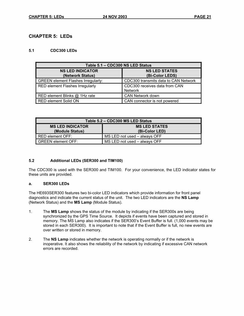
CHAPTER 5: LEDs 5.1 CDC300 LEDs
Table 5.1 – CDC300 NS LED Status NS LED INDICATOR
(Network Status) NS LED STATES (Bi-Color LEDS)
GREEN element Flashes Irregularly: CDC300 transmits data to CAN Network RED element Flashes Irregularly CDC300 receives data from CAN
Network RED element Blinks @ 1Hz rate CAN Network down RED element Solid ON CAN connector is not powered
Table 5.2 – CDC300 MS LED Status MS LED INDICATOR
(Module Status) MS LED STATES (Bi-Color LED)
RED element OFF: MS LED not used – always OFF GREEN element OFF: MS LED not used – always OFF
5.2 Additional LEDs (SER300 and TIM100) The CDC300 is used with the SER300 and TIM100. For your convenience, the LED indicator states for these units are provided. a. SER300 LEDs The HE693SER300 features two bi-color LED indicators which provide information for front panel diagnostics and indicate the current status of the unit. The two LED indicators are the NS Lamp (Network Status) and the MS Lamp (Module Status). 1. The MS Lamp shows the status of the module by indicating if the SER300s are being
synchronized by the GPS Time Source. It depicts if events have been captured and stored in memory. The MS Lamp also indicates if the SER300’s Event Buffer is full. (1,000 events may be stored in each SER300). It is important to note that if the Event Buffer is full, no new events are over written or stored in memory.
2. The NS Lamp indicates whether the network is operating normally or if the network is
inoperative. It also shows the reliability of the network by indicating if excessive CAN network errors are recorded.
PAGE 22 24 NOV 2003 CHAPTER 5: LEDs
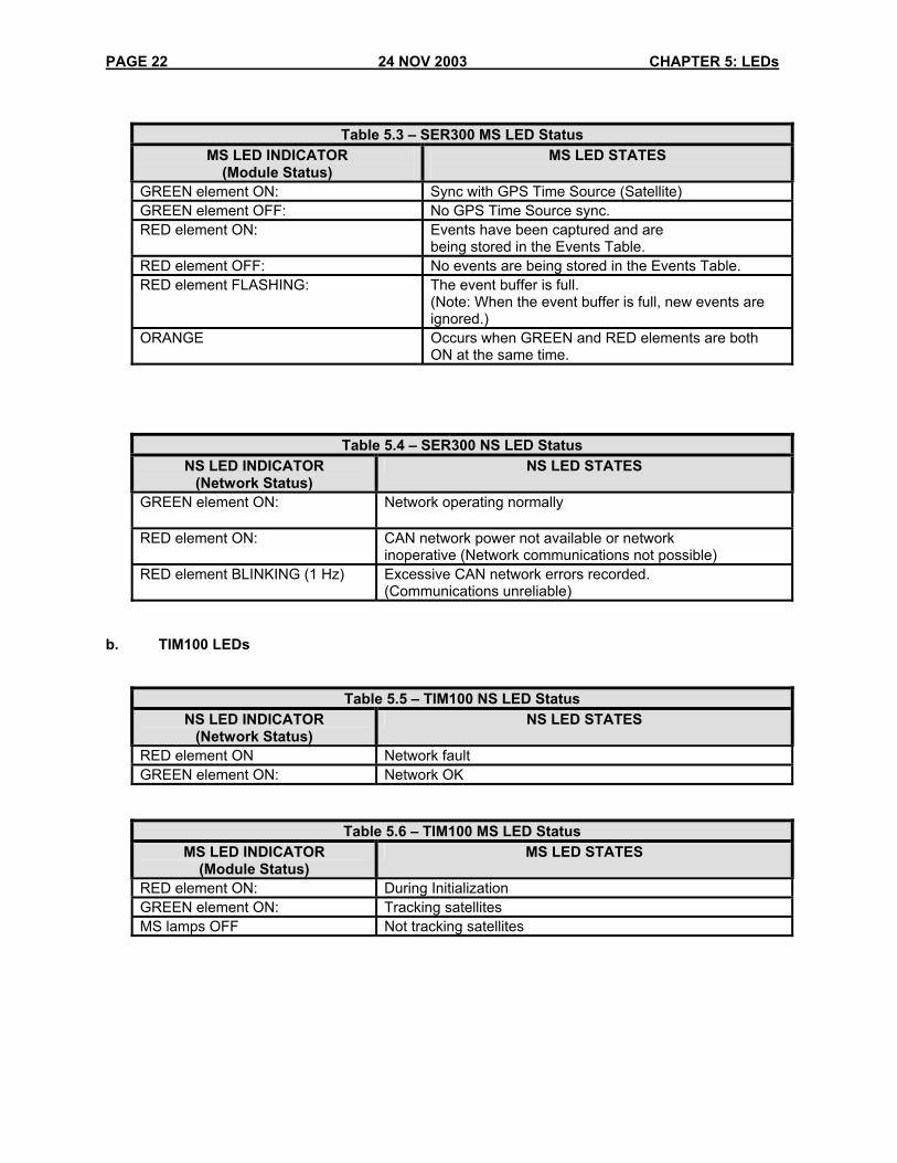
Table 5.3 – SER300 MS LED Status
MS LED INDICATOR (Module Status)
MS LED STATES
GREEN element ON: Sync with GPS Time Source (Satellite) GREEN element OFF: No GPS Time Source sync. RED element ON: Events have been captured and are
being stored in the Events Table. RED element OFF: No events are being stored in the Events Table. RED element FLASHING: The event buffer is full.
(Note: When the event buffer is full, new events are ignored.)
ORANGE Occurs when GREEN and RED elements are both ON at the same time.
Table 5.4 – SER300 NS LED Status NS LED INDICATOR
(Network Status) NS LED STATES
GREEN element ON: Network operating normally
RED element ON: CAN network power not available or network inoperative (Network communications not possible)
RED element BLINKING (1 Hz) Excessive CAN network errors recorded. (Communications unreliable)
b. TIM100 LEDs
Table 5.5 – TIM100 NS LED Status NS LED INDICATOR
(Network Status) NS LED STATES
RED element ON Network fault GREEN element ON: Network OK
Table 5.6 – TIM100 MS LED Status MS LED INDICATOR
(Module Status) MS LED STATES
RED element ON: During Initialization GREEN element ON: Tracking satellites MS lamps OFF Not tracking satellites