Camshaft Position Intake Actuator Replacement -...
21
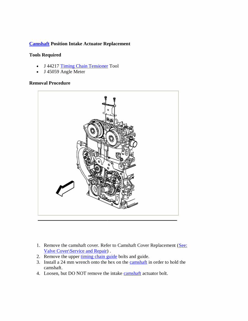
Camshaft Position Intake Actuator Replacement Tools Required J 44217 Timing Chain Tensioner Tool J 45059 Angle Meter Removal Procedure 1. Remove the camshaft cover. Refer to Camshaft Cover Replacement ( See: Valve Cover\Service and Repair ) . 2. Remove the upper timing chain guide bolts and guide. 3. Install a 24 mm wrench onto the hex on the camshaft in order to hold the camshaft. 4. Loosen, but DO NOT remove the intake camshaft actuator bolt.
-
Upload
phungtuyen -
Category
Documents
-
view
223 -
download
3
Transcript of Camshaft Position Intake Actuator Replacement -...
Camshaft Position Intake Actuator Replacement
Tools Required
J 44217 Timing Chain Tensioner Tool
J 45059 Angle Meter
Removal Procedure
1. Remove the camshaft cover. Refer to Camshaft Cover Replacement (See:
Valve Cover\Service and Repair) .
2. Remove the upper timing chain guide bolts and guide.
3. Install a 24 mm wrench onto the hex on the camshaft in order to hold the
camshaft.
4. Loosen, but DO NOT remove the intake camshaft actuator bolt.

Important: Ensure that the tips of the J 44217 are fully engaged into the timing
chain.
5. Install one of the tools (1) from the J 44217 to the exhaust camshaft side of the
timing chain assembly in order to retain the timing chain. Firmly tighten the
nuts.

Important: Ensure that the tips of the J 44217 are fully engaged into the timing
chain.
6. Install one of the tools (1) from the J 44217 to the intake camshaft side of the
timing chain assembly in order to retain the timing chain. Firmly tighten the
nuts.
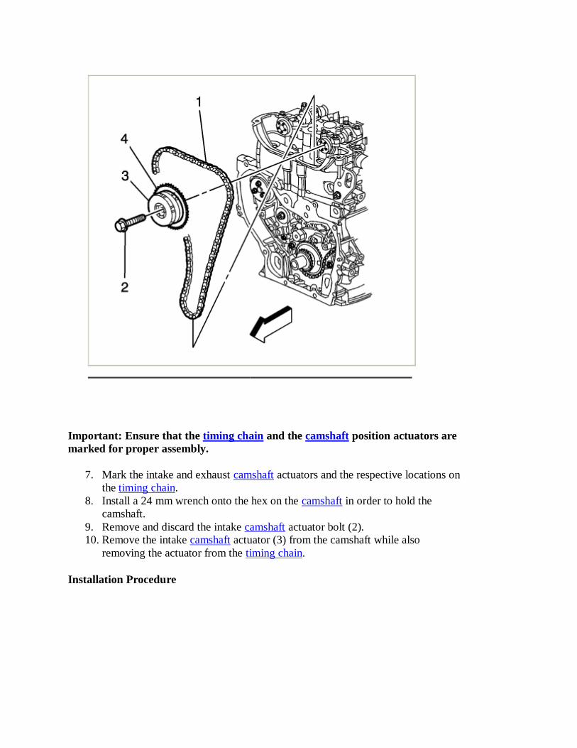
Important: Ensure that the timing chain and the camshaft position actuators are
marked for proper assembly.
7. Mark the intake and exhaust camshaft actuators and the respective locations on
the timing chain.
8. Install a 24 mm wrench onto the hex on the camshaft in order to hold the
camshaft.
9. Remove and discard the intake camshaft actuator bolt (2).
10. Remove the intake camshaft actuator (3) from the camshaft while also
removing the actuator from the timing chain.
Installation Procedure

Important: Ensure that the alignment mark made previously on the exhaust
camshaft actuator is still aligned properly with the mark on the timing chain.
1. Install the timing chain onto the intake camshaft actuator.
2. Align the intake camshaft actuator alignment mark made previously with the
timing chain mark and install the actuator onto the camshaft.
3. Install a NEW intake camshaft actuator bolt (2) until snug.

4. Remove the tool (1) from the intake camshaft side of the timing chain
assembly.

5. Remove the tool (1) from the exhaust camshaft side of the timing chain
assembly.
6. Install a 24 mm wrench onto the hex on the camshaft in order to hold the
camshaft.
Notice: Refer to Fastener Notice .
7. Tighten the NEW camshaft actuator bolt.
Tighten the bolt to 85 N.m (63 lb ft), plus an additional 30 degrees using the J
45059 .

8. Install the upper timing chain guide and bolts.
Tighten the bolts to 10 N.m (89 lb in).
9. Install the camshaft cover.
Camshaft Position Exhaust Actuator Replacement
Tools Required

J 44217 Timing Chain Tensioner Tool
J 45027 Tensioner Tool
J 45059 Angle Meter
Removal Procedure
1. Remove the camshaft cover. Refer to Camshaft Cover Replacement (See:
Valve Cover\Service and Repair) .
2. Remove the upper timing chain guide bolts and guide.

3. Remove the timing chain tensioner.
4. Install a 24 mm wrench onto the hex on the camshaft in order to hold the
camshaft.
5. Loosen, but DO NOT remove the exhaust camshaft actuator bolt.

Important: Ensure that the tips of the J 44217 are fully engaged into the timing
chain.
6. Install one of the tools (1) from the J 44217 to the exhaust camshaft side of the
timing chain assembly in order to retain the timing chain. Firmly tighten the
nuts.

Important: Ensure that the tips of the J 44217 are fully engaged into the timing
chain.
7. Install one of the tools (1) from the J 44217 to the intake camshaft side of the
timing chain assembly in order to retain the timing chain. Firmly tighten the
nuts.

Important: Ensure that the timing chain and the camshaft position actuators are
marked for proper assembly.
8. Mark the intake and exhaust camshaft actuators and the respective locations on
the timing chain.
9. Install a 24 mm wrench onto the hex on the camshaft in order to hold the
camshaft.
10. Remove and discard the exhaust camshaft actuator bolt (2).
11. Remove the exhaust camshaft actuator (3) from the camshaft while also
removing the actuator from the timing chain.
Installation Procedure

Important: Ensure that the alignment mark made previously on the intake
camshaft actuator is still aligned properly with the mark on the timing chain.
1. Install the timing chain onto the exhaust camshaft actuator.
2. Align the exhaust camshaft actuator alignment mark made previously with the
timing chain mark and install the actuator onto the camshaft.
3. Install a NEW exhaust camshaft actuator bolt (2) until snug.

4. Remove the tool (1) from the intake camshaft side of the timing chain
assembly.

5. Remove the tool (1) from the exhaust camshaft side of the timing chain
assembly.
6. Install a 24 mm wrench onto the hex on the camshaft in order to hold the
camshaft.
Notice: Refer to Fastener Notice .
7. Tighten the NEW camshaft actuator bolt.
Tighten the bolt to 85 N.m (63 lb ft), plus an additional 30 degrees using the J
45059 .

8. Remove the old oil from the timing chain tensioner.
9. Inspect the timing chain tensioner for scoring or free movement.
10. Inspect the timing chain washer and O-ring for damage. If damaged, replace
the timing chain tensioner.
11. Measure the timing chain tensioner assembly from end to end. A NEW
tensioner should be supplied in the fully compressed non-active state. A
tensioner in the compressed state will measure 72 mm (2.83 in) from end to end
(a). A tensioner in the active state will measure 85 mm (3.35 in) from end to
end (a).

12. If the timing chain tensioner is not in the compressed state, perform the
following steps:
1. Remove the piston assembly from the body of the timing chain tensioner by
pulling it out.
2. Install the J 45027-2 (2) into a vise.
3. Install the notch end of the piston assembly into the J 45027-2 (2).
4. Using the J 45027-1 (1), turn the ratchet cylinder into the piston.

13. Inspect the bore of the tensioner body for dirt, debris, and damage. If any
damage appears, replace the tensioner. Clean dirt or debris with a lint free
cloth.
14. Install the compressed piston assembly back into the timing chain tensioner
body until the assembly stops at the bottom of the bore. do not compress the
piston assembly against the bottom of the bore. If the piston assembly is
compressed against the bottom of the bore, the assembly will activate the
tensioner, which will then need to be reset again.
15. At the point the tension should measure approximately 72 mm (2.83 mm) from
end to end (a). If the tensioner does not measure 72 mm (2.83 mm) from end to
end (a) repeat steps 8.1 through 8.4.

16. Ensure that all dirt and debris is removed from the timing chain tensioner
threaded hole in the cylinder head.
17. Install the timing chain tensioner.
Tighten the tensioner to 75 N.m (66 lb ft).
18. The timing chain tensioner is released by compressing the tensioner 2 mm
(0.079 in) which will release the locking mechanism in the ratchet. To release
the timing chain tensioner, use a suitable tool with a rubber tip on the end. Feed
the tool down through the cam chest to rest on the timing chain, then give a
sharp jolt diagonally downwards to release the tensioner.

19. Install the upper timing chain guide and bolts.
Tighten the bolts to 10 N.m (89 lb in).
20. Install the camshaft cover.