Camlok Clamps Catalog (CMR-CAMLOK-0713)...
28
COLUMBUS McKINNON CORPORATION LIFTING CLAMPS VERTICAL PLATE HORIZONTAL PLATE NON-MARKING GIRDER PILE PINCHING HAND GRIP SCREW BEAM LIFTING LUGS
Transcript of Camlok Clamps Catalog (CMR-CAMLOK-0713)...

C O L U M B U S M c K I N N O N C O R P O R A T I O N
LIFTING CLAMPS
VERTICAL PLATE
HORIZONTAL PLATE
NON-MARKING
GIRDER
PILE PINCHING
HAND GRIP
SCREW
BEAM
LIFTING LUGS

2
Columbus McKinnon has been manufacturing material handling equipment for over 138 years. It is our goal to manufacture high quality, long lasting lifting products that will safely increase productivity.
Camlok lifting clamps are part of an extensive portfolio of rigging and below-the-hook attachments from Columbus McKinnon. The Camlok line of clamps address a multitude of application needs and provide secure lifts for a variety of loads including:
Structural Steel Plate Stainless Steel Iron Aluminum Girders & Beams Sheet Plates Steel Piles Rolled Steel Joists Manhole Pipes Shipping Containers

3
Mechanics of a Clamp ........................ 4
How to Select the Proper Clamp.......... 5
CZ Vertical Plate Clamp ....................... 6
CY & CX Hinged Plate Clamp .............. 8
LJ Non-Marking Clamp ...................... 10
TTR Girder Clamp .............................. 11
CH Horizontal Plate Clamp ................ 12
THK Horizontal Plate Clamp............... 13
CP Pile Pinching Clamp ..................... 14
HGC Hand Grip Clamp ....................... 15
THS Horizontal Plate Clamp ............... 16
TSH Screw Clamp .............................. 17
HG Vertical Plate Clamp ..................... 18
CG Girder Turning Clamp ................... 19
TTG Horizontal Girder Clamp ............. 20
BTG Groundworks .............................. 21
Screwlok Beam Clamp with Shackle ....................................... 22
SC Twin Beam Clamp......................... 23
CLB Lifting Lug ................................... 24
CLB Lifting Lug Safety ....................... 25
92 Series & C2 Spare Parts ................ 26
CY & CX Spare Parts .......................... 27
INDEX

4
MECHANICS OF A CLAMPThe maximum load imposed on a device determines the structure and size of a plate clamp. The manufacturer will design the internal components of the clamp to cope with these forces in consideration to the expected mechanical losses of the system.
Most Camlok clamps use sharp teeth to bite into the plate being lifted. Once a clamp has bitten into the plate, it effectively becomes one with the plate and therefore the plate can be safely lifted. The design of the clamp is such that the load applied to the hook ring is magnified through a system of links to give a high gripping force to push the jaw teeth into the lifted plate. This gripping force is directly proportional to the load applied and self actuating (i.e. the higher the load applied, the higher the gripping force). This is known as the primary action.
A secondary force generated by movement in the lifted plate supplements the primary gripping force, if the plate starts to slip from the clamp, the moving jaw is turned with the plate and the cam shape of the jaw increases the gripping force.
Plate lifting clamps are simple machines. Like all machines with mechanisms they are subjected to naturally occurring phenomenon that reduce efficiency. The phenomenons include:
Friction between moving parts. This will reduce the forces transmitted through the mechanism. Inertia of the components. This will assert a degree of drag into the system slowing the reaction to changing inputs.
The system of links and pivots in a plate clamp are simple, lightweight, and move over a small distance when in operation. The bearings in a plate clamp are generally simple “metal on metal” type, have large forces acting through them, and have poor lubrication. Therefore, the friction loss can be significant if the clamp is poorly maintained and suffering wear.
The mechanism of the plate clamp is not static during operation but the movements are small. The inertia and friction of the mechanism can have a significant effect on the performance of the clamp when lifting material from the horizontal to the vertical position. The imposed load on the clamp fluctuates from 50% of the load being lifted to zero and then to 100% at the “top dead center” position. (The point when the center of gravity of the plate passes over the pivot point contact on the floor and is then lifted clear.)
The amount a tooth penetrates into the lifted plate is dependent on a number of factors:
The gripping force The hardness of the plate being lifted. The shaped of the clamp tooth
In simple terms, a tooth will penetrate into the material until the gripping force divided by the projected area of the tooth contact equals the indent stress of the material.
LOAD
LOAD
NO LOAD
NO RESISTANCE TO PIVOTING
LOAD
RESISTANCE TO PIVOTING
SQUARE VS. ROUND PADS
SQUARE ROUND
Pivoting Resistance Excellent Poor
Teeth Wear Excellent Average
Full Surface Contact Excellent Poor
Load Distribution Excellent Poor
Pad Bolt Stress Low High
CAMLOK LIFTING PAD & JAW DESIGN
SQUARE PADS Unlike round pads on the market, Camlok uses a wide spacing or square pad layout. The wide spacing and layout of the teeth on the Camlok square pad help prevent pivoting of the plate and clamp during lifting. This protects the straight teeth on the moving jaw. All the teeth on the square pad can be considered to lift the load therefore maximizing efficiency. The pads are marked with the maximum material hardness.
ROUND PADS On round pads the gripping force must push all the teeth into the material. However, only the top and bottom quarter of the pad can be considered to effectively lift the load, thus reducing the efficiency of the pad. There is no resistance to pivoting and straight teeth on the jaw suffer rotational stress and wear.
CAMLOK JAW The prevention of load twisting by the wide pad and teeth layout on the Camlok clamp eliminates any twisting or pivoting load on the jaws. This helps prevent any unnecessary wear or damage on the teeth.
The force of the load on the Camlok clamp is distributed through the pad directly to the clamp housing. This means there is no load stress on the pad bolts and reduces the possibility of pad bolt failure during lifting.
Figure 1. When the load on round pads twists, the narrow jaw resists it. This places very high loads on the edge of the jaw which is not designed to sustain this pivoting load.
FIGURE 1

5
HOW TO SELECT THE RIGHT CLAMP FOR YOUR APPLICATIONFor efficient, reliable, and secure operation of a lifting clamp, the selection of the correct clamp for the job is of paramount importance. Clamps can be used on most types and grades of steel up to a surface hardness of 300 Brinell (32HRc), and are suitable for certain grades of aluminum sheet and brass. Clamps are not suitable for steel over 300 Brinell (32HRc), stainless steel, lead, certain grades of copper and materials over 120ºC or 250ºF surface temperature.
DETERMINING PROPER SIZE The working load limit (WLL) of the clamp should be as close as possible to the actual load to be lifted. This ensures the clamp is working at maximum efficiency, reduce wear, and increase the clamp’s service life. The maximum jaw capacity of the clamp should also be as close as possible to the plate thickness being lifted. The spring will be stretched to its maximum and will be providing the maximum amount of initial grip to the lift.
Excessive wear and a reduction in working life can be caused if a clamp is continuously used to lift the same thickness material. With this type of application, the teeth of the clamp’s moving jaw where the wear is concentrated must be inspected regularly. Scheduled or periodic rotation of duties, will increase the operational life of a company’s inventory of clamps. Speciality clamps can be manufactured for specific needs as well.
DETERMINING PROPER TYPE For lifting thin light sheets, operators should choose a narrow throat clamp. The pad side of a narrow throat clamp is closer to the moving jaw, thus increases the initial grip of the clamp by causing the spring to be stretched.
For lifting thick, but small, plates, the best solution is larger clamps where the pad side is further away from the moving jaw.
For lifting loads of made of hardened steel, the operator should avoid using clamps with teeth which may damage the load. Non-marking clamps should be used instead.
CHOOSE AN ACCREDITED & EXPERIENCED SOURCE Camlok is accredited by BSI (British Standards) and is a member of the Lifting Equipment Engineers Association (LEEA). Our clamps are designed in accordance with ISO9002. Whether you need a single clamp or a complete lifting system that include forged rigging attachments, hoists and overhead cranes, count on the decades of engineering and application-driven experience provided by Columbus McKinnon and Camlok.

6
CZ SERIES Vertical Plate Clamps
The CZ & 92 series of plate clamps can be used on all hot rolled structural steel plates and sections up to a
surface hardness of 300 Brinell (32HRc). They can be used to lift plate from the horizontal to vertical position
and vice versa through 180º. This series is fitted with a hold open and lock closed device. To initiate the self
actuating force, a spring is incorporated into the clamp to give an initial bite on the material. If the plate should
start to slip during lifting, the cam shape of the jaw turns with the material and increases the gripping force.
The cam handle has been ergonomically designed with a flat surface to allow ease of operation while wearing
protective gloves. The cam handle connects to the cam via a robust square drive.
Unlike other clamps, Camlok plate clamps are designed with a sloping slot, which increases the grip on the
load when the clamp is in the horizontal position.
Used on all hot rolled structural steel plates and sections up to a surface hardness of 300 Brinell (32HRc)
Available in capacities of ½ ton up to 33 tons
Jaw capacities available up to maximum of 5-1/8"
Lifts plates from horizontal to vertical position and vice versa through 180º
Clamp has serrated teeth and will mark plate
Select a clamp with a working load limit as close as possible to the actual load being lifted and the maximum jaw capacity should be as close as possible to the plate thickness
Repair centers available to service your products
Replacement parts available for clamps

7
Min MaxA B C D E F G H
lb. in. in. in. in. in. in. in. in. in. lb.92 500 120 1,100 0 to 5/8 3.898 7.677 1.142 1.299 1.850 1.969 1.890 0.433 3.392 1500 350 3,300 0 to 3/4 4.961 8.858 1.969 1.929 2.756 3.228 2.165 0.472 6.692 2000 450 4,400 0 to 1-1/4 7.559 12.283 3.150 2.953 3.780 3.937 3.189 0.787 17.692 3000 675 6,600 0 to 1-1/4 7.559 12.283 3.150 2.953 3.780 3.937 3.189 1.181 22.0CZ4 1,100 8,800 0 to 1-1/4 7.756 14.606 3.150 2.677 3.661 5.079 0.787 1.181 26.5CZ4L* 1,100 8,800 1-1/8 to 2-3/8 8.976 15.354 3.150 2.677 3.661 5.079 0.787 1.181 39.7CZ6 1,600 13,200 0 to 2 11.535 19.055 3.504 3.740 5.630 5.079 0.984 1.378 46.3CZ8 2,150 17,600 0 to 2 11.535 19.370 3.504 3.740 5.630 5.079 0.984 1.654 57.3CZ8L* 2,150 17,600 2 to 4 14.252 20.630 3.504 4.488 5.630 5.079 0.984 1.654 70.5CZ10 3,350 22,000 0 to 2 11.535 21.457 4.331 3.740 5.630 5.472 0.984 1.772 66.1CZ10L 3,350 22,000 2 to 4 14.252 21.457 4.331 4.488 5.630 5.472 0.984 1.772 81.6CZ15* 6,650 33,000 0 to 2 14.173 24.134 5.118 4.921 6.378 8.031 1.772 2.165 165.3
CZ20* 8,850 44,000 0 to 2-1/2 18.189 29.724 5.118 6.496 8.268 9.252 1.772 2.559 271.2CZ20L* 8,850 44,000 2-1/2 to 5 22.047 31.693 5.118 7.677 8.268 9.252 1.772 2.559 299.8CZ30* 13,250 66,000 0 to 2-1/2 18.189 28.819 2.362 6.496 8.268 11.614 2.559 - 429.9
Weight
Dimensions
ModelJaw
Capacity
lb.
WorkingLoad Limit
Dont’s
E
A
D F
B
C
G
H
DO NOT side load clamp more than 15º - use type CY or CX clamp for side loading
DO NOT lift plates with a temperature of 120ºC/ or 250ºF
DO NOT use to lift stainless steel, lead, and copper. For stainless steel plate, use LJ or HG Clamp.
DO NOT use on a double, triple, or quad sling. When using two clamps to lift a steel plate, a lifting beam must be used between the two clamps, so the clamps operate in a vertical position. Use a CY or CX clamp for slings with more than one leg.
CZ SERIES Vertical Plate Clamps
Weight of plate to lift
Hardness of plate to lift
Type of material to lift
Position of plate to lift
Can plate be marked, is a non marking clamp required?
Things to Remember
SPECIFICATIONS
* Products available upon request

8
Used on all hot rolled structural steel plates and sections up to a surface hardness of 300 Brinell (32HRc)
Available in capacities of 1 ton up to 10 tons
Jaw capacities available up to maximum of 4"
Lifts plates from horizontal to vertical position and vice versa through 180º
Clamps can be used with 2 leg slings
Clamp has serrated teeth and will mark plate
Select a clamp with a working load limit as close as possible to the actual load being lifted and the maximum jaw capacity should be as close as possible to the plate thickness
Repair centers available to service your products
Replacement parts available for clamps
The CY series of plate clamps can be used on all structural steel plates up to surface hardness of 300 Brinell.
These clamps are designed to be used with two leg chain sling for lifting longer plates. With the swiveling hook
ring, the CY series of clamps can be fitted to a steel plate in any position. These clamps can turn a plate from
the horizontal to vertical lift over the edge. Sufficient clamping of the load is achieved by this special shape of
the hook ring.
The CX series clamps are a more robust heavy duty model of the CY clamp. The CX clamp has a reinforced
plate at the top of the mouth, and a heavy duty hook ring. The CX clamp is more suitable for turning vertically
racked plates.
CY & CX SERIES Hinged Plate Clamps
CY SERIES
CX SERIES
Dont’s DO NOT lift loads less than 20% of Working Load Limit of clamp
DO NOT lift plates with a temperature of 120ºC/ or 250ºF
DO NOT use to lift stainless steel, lead, and copper. For stainless steel plate, use LJ or HG Clamp.

9
Min MaxA B C D E F G H I
lb. lb. in. in. in. in. in. in. in. in. in. in. lb.CY1 450 2,200 0 to 3/4 4.961 10.630 1.969 1.929 2.756 3.740 2.480 0.472 0.906 10.1CY2 900 4,400 0 to 1-1/4 7.559 15.039 3.150 2.953 3.780 5.197 3.622 0.787 1.181 26.5CY3 1,350 6,600 0 to 1-1/4 7.559 15.039 3.150 2.953 3.780 5.197 3.622 0.787 1.181 30.9
Weight
Dimensions
ModelJaw
Capacity
WorkingLoad Limit
Min MaxA B C D E F G H I
lb. in. in. in. in. in. in. in. lb.CX3000 1,000 6,600 0 to 1-1/4 7.756 20.276 2.638 5.433 0.748 2.677 3.661 3.189 4.331 26.5CX6000 2,650 13,200 0 to 2 11.496 29.016 3.740 6.929 1.102 3.740 5.630 5.394 7.402 83.8CX6000L* 2,650 13,200 2 to 4 14.449 30.906 3.858 7.087 1.102 4.528 5.630 5.315 7.402 105.8CX8000* 3,550 17,600 0 to 2 11.496 29.016 3.858 6.929 1.102 3.740 5.630 5.354 8.268 86.0CX8000L* 3,550 17,600 2 to 4 14.449 30.906 3.858 7.087 1.102 4.528 5.630 5.354 8.268 112.4CX10000* 4,400 22,000 0 to 2 14.173 35.551 4.331 7.677 1.299 4.921 6.378 6.693 8.780 134.5CX10000L* 4,400 22,000 2 to 4 17.559 36.260 4.409 7.677 1.299 6.614 6.378 6.693 8.780 167.5
Weight
Dimensions
ModelJaw
Capacity
lb. in. in. in.
WorkingLoad Limit
E
AD
G
B
C
FH
I E
A
D
F
B
G
H
C
I
CY & CX SERIES Hinged Plate Clamps
CY SPECIFICATIONS
CX SPECIFICATIONS
CY CX
120
90
30
LOAD
CY1 CY2 CY3
degrees lb. lb. lb.0-30 4,400 8,800 13,200
30-90 2,200 4,400 6,600
90-120 1,100 2,200 3,300
Imperial
AngleModel Code
CY SERIESCX SERIES

10
The LJ clamp can be used on all structural plates, stainless steel, iron, timber, and aluminum without marring or damaging the surface. Lifts plates from the horizontal to vertical position and vice versa through 180º.
Suitable for steel with a surface hardness above 300 Brinell (32HRc)
Available in capacities up to 1-1/2 tons
The LJ clamp can be used on thin plates. Minimum load will not affect the LJ clamps as they do not have teeth for bite. However some load is required to combat friction in the clamp. Extra care must be taken when lifting plates in the lower 20% of their rated capacity. Thin plates are best lifted with the fixed jaw on top when performing a horizontal to vertical lift.
Repair centers available to service your products
Replacement parts available for clamp
The Camlok LJ series of plate clamps can be used to lift and turn all structural steel plates including
stainless steel, iron, and aluminum without marking or damaging the surface. The clamp may not be suitable
for lifting highly polished plates where the polish process may leave lubricating compounds. The performance
on the leather jaws is not affected by standing water so the clamp can be used with submerged plasma cutting
machines. The LJ clamp is suitable for surface hardness greater than 300 Brinell (32HRc).
Min MaxA B C D E F
lb. lb. in. in. in. in. in. in. in. lb.LJ500 60 1,100 0 to 3/8 5.000 7.874 2.165 2.047 2.717 2.992 7.7LJ1500 400 3,300 0 to 3/4 8.465 13.583 3.346 2.953 5.315 4.646 26.5
Weight
Dimensions
ModelJaw
CapacityWorking
Load Limit
E
A
DF
B
C
Always remember, your non marring clamps need care in use because you are relying on friction to grip the load.
LJ SERIES Non Marking Clamps
SPECIFICATIONS
Do’s & Dont’s DO NOT use the clamp on plates with surface contamination (dirt, grease, scale, etc...). Minimize dirt and dust on the surface to be lifted. Pads can tolerate surface water on the plate but shall not be submerged under water.
DO NOT use on smooth polished surfaces. The polished surfaces leave behind lubricating compounds. The leather pads need to surround the irregularities in the surface to grip the load effectively.
DO clean the leather pads regularly, clean in water only and use a brass suede brush to rough up the surface.
DO NOT use solvents to clean the jaw lining as this may affect the bond between the surface material and the metal of the jaw.
DO inspect the clamp before each use. Make sure the pads are clean. If pads are cut or worn, or can not be cleaned, take clamp out of service and replace pads. When in doubt, remove clamp from service.
11
Used to lift and transport structural beams up to a surface hardness of 300 Brinell (32HRc) with the flanges in the up right position
Available in capacities up to 3 tons
Jaw capacities available up to maximum of 1-1/8"
Short beams may be lifted with a single clamp, longer beams should use 2 clamps and a spreader beam
Repair centers available to service your products
Replacement parts available for clamps
No special tools required for repairs
The TTR clamps can be used on girders and rolled steel joists up to a surface hardness of 300 Brinell (32HRc).
This range of clamps has been developed for handling structural beams with the flange in a vertical position,
or “H” position. Girders can be lifted and stacked horizontally. The hook rings are designed to be as a near to
the center of gravity as possible, resulting in a near horizontal lift. For short beams a single clamp can be used.
For longer beams, two clamps should be used in combination with a lifting beam. Various sizes and lifting
capacities are available. The TTR is a versatile tool for transporting girders and joists. This clamp is fitted with
a cam operated locking mechanism.
Min MaxA B C D E F
lb. lb. in. in. in. in. in. in. in. lb.TTR750 90 1,600 1/4 to 5/8 5.375 7.500 2.000 1.750 2.375 3.500 7.7TTR1500 350 3,300 1/4 to 1 7.500 10.625 2.625 2.625 3.000 4.875 22.0TTR3000* 700 6,600 1/4 to 1 8.250 9.875 3.500 2.625 3.375 5.000 26.5
Weight
Dimensions
Model Flange Working
Load Limit
E
A
D
F
B
C
TTR SERIES Girder Clamps
SPECIFICATIONS
* Products available upon request
Dont’s DO NOT lift plates with a temperature of 120ºC/ or 250ºF
DO NOT use to lift stainless steel, lead and copper

12
CH clamps must be used in pairs
Available in pair capacities of 1 ton up to 10 tons
Jaw capacities available up to maximum of 6"
CH clamps have smooth teeth and can be used on all types of material
A single pair of CH clamps can be used with a 2 leg sling
CH clamps can be furnished with serrated teeth
When serrated teeth are used, maximum hardness of material to lift should not exceed 300 Brinell
Integral shackle on the CH clamp designed to accept relevant size chain sling hook
CH clamps can be designed to suit any load or plate thickness
Repair centers available to service your products
Replacement parts available for clamps
The CH clamps are sold in pairs and can be used on all types of materials in plate form, providing the plate
can withstand the forces imposed. Standard CH clamps are supplied with smooth jaws. The clamps are
suitable for lifting one plate at a time, or bundles of plates provided the plates are the same width, have straight
square sides, and are thicker than 10% of the maximum jaw capacity of the clamp. CH clamps should never
be side loaded. The smooth jaws can be replaced with serrated hardened steel teeth and used on material up
to 300 Brinell (32HRc).
A B C D E F G
lb. in. in. in. in. in. in. in. lb.CH1 2,200 1/4 to 1-1/4 1.181 3.228 2.362 3.937 1.260 1.732 0.512 13.2CH2 4,400 1/4 to 1-1/4 1.181 3.228 2.362 3.937 1.969 2.874 0.709 24.3CH2/L 4,400 3/4 to 2 1.181 3.228 2.362 3.937 1.969 2.874 0.709 26.5CH4 8,800 1/4 to 1-1/4 1.575 4.409 3.150 3.937 2.520 3.622 0.984 37.5CH4/L 8,800 2 to 4 1.575 4.409 3.150 3.937 2.520 3.622 0.984 50.7CH6 13,200 1/4 to 3 2.165 6.772 3.937 5.118 3.543 5.118 1.378 101.4CH6/L 13,200 2 to 5 2.165 6.772 3.937 5.118 3.543 5.118 1.378 123.5CH8 17,600 1/4 to 3 2.165 6.772 4.134 5.118 3.543 5.118 1.378 116.8
CH8/L 17,600 2 to 5 2.165 6.772 4.134 5.118 3.543 5.118 1.378 132.3CH10 22,000 1/4 to 4 2.559 8.465 4.724 5.906 4.488 5.118 1.378 209.4CH10/L 22,000 2 to 6 2.559 8.465 4.724 5.906 4.488 5.118 1.378 238.1HH8* 17,600 1/4 to 2 2.165 6.614 4.134 5.118 4.134 5.118 3.543 46.3HH8/L 17,600 2 to 4 2.165 6.614 4.134 5.118 3.543 4.488 1.378 61.7
WeightDimensions
ModelWorking
Load Limit JawCapacity
in.
(per pair) (per pair)
CH SERIES Horizontal Plate Clamps
SPECIFICATIONS
* Products available upon request
Dont’s DO NOT use CH clamps for side loading

13
THK clamps must be used in pairs
Available in pair capacities of 3/4 ton up to 9 tons
Jaw capacities available up to maximum of 2-1/4"
Clamp has serrated teeth and will mark plate
A single pair of THK clamps can be used with a 2 leg sling
CH clamps can be furnished with serrated teeth
Maximum hardness of material to lift should not exceed 300 Brinell (32HRc)
Repair centers available to service your products
Replacement parts available for clamps
The THK Series Clamp has a jaw that pivots in the reverse direction to our normal horizontal clamps and is
designed to lift and handle thin sheet plate that tends to sag when being lifted. The reverse jaw feature ensures
that the grip of the clamp increases the more the plate deflects under its own self weight. Clamps are used
in pairs with a two legged chain sling. Two pairs of clamps supported from a lifting beam must be used when
handling long plates. Single plates only can be lifted.
Min MaxA B C D E F
lb. lb. in. in. in. in. in. in. in. lb.THK750 90 1,600 0 to 1 4.625 5.375 0.750 1.000 2.875 3.125 6.6THK1500 200 3,300 0 to 1-3/8 5.375 6.625 1.000 1.250 3.125 3.500 13.2THK4500* 500 9,900 0 to 1-3/4 8.625 8.625 1.750 4.000 4.375 4.375 35.3THK6000* 700 13,200 0 to 2-3/8 8.375 10.500 1.375 1.875 4.875 4.375 50.7THK9000 1,000 19,800 0 to 2-3/8 8.750 11.375 1.625 2.250 4.500 5.500 77.2
WeightDimensions
Model Plate(per pair)
WorkingLoad Limit(per pair)
EA
D
F
B
C
30º 30º
SPECIFICATIONS
THK SERIES Horizontal Plate Clamps
* Products available upon request
Dont’s DO NOT use THK clamps with 3 or 4 leg slings, use a spreader beam

14
Designed specifically for pitching sheet steel piling
Ideal clamp for heavy construction
Rope is fitted for easy release from the ground
Available up to 5 ton capacity
Repair centers available to service your products
Replacement parts available for clamps
The CP clamps are designed specifically for pitching sheet steel and have the advantage of an attached rope
for easy release from the ground. The rope presents a quicker method than the laborious procedure of release
using a standard shackle. Piles must be prepared with a pitching hole of correct dimensions. These clamps are
not designed to extract a driven pile and must not be used to remove piles under any circumstances. For pile
removal use the PP series clamps.
A B C D E F
lb. in. in. in. in. in. in. lb.CP2 4,400 8.976 0.787 2.000 0.787 16.750 8.500 41.9CP3 6,600 8.976 1.024 2.500 1.181 17.875 8.875 50.7CP5 11,000 8.976 1.378 3.250 1.181 19.875 9.500 72.8
Weight
Dimensions
ModelWorking
Load Limit
E
A
D
F
B
C
CP SERIES Pile Pinching Clamps
SPECIFICATIONS

15
Designed for manual lifts
Maximum working load limit 500 lbs.
Pre-tensioned serrated teeth for secure grip
Suitable for material thickness up to 3/8"
Excellent clamp for workshop use
Prevents plate slippage
Maximum hardness of material to lift should not exceed 300 Brinell (32HRc)
Repair centers available to service your products
Replacement parts available for clamps
The Camlok hand grip clamp is designed to carry or pull any object that will fit into the jaws. It can be
used on all structural steel plates and sections up to a surface hardness of 300 Brinell. This clamp is not
suitable for steel over 300 Brinell (32HRc), stainless steel, lead, copper and materials over 120ºC/ 250ºF surface
temperature. The hand clamp is used to manually lift and carry material in a workshop environment. The
innovative design enables the operator to open and attach the clamp to sheet material by depressing the lifting
handle. Two pre-tensioned hardened serrated toothed jaws grip the sheet securely when the handle is released.
A B C D E F G H
lb. in. in. in. in. in. in. in. in. lb.HGC 500 0 to 3/8 4.25 7.25 3.875 1.875 2.125 0.875 0.375 5.125 2.0
WeightModel Plate
Dimensions
in.
WorkingLoad Limit
B
G
C
H
A
D
F = Thickness
HGC SERIES Hand Grip Clamps
SPECIFICATIONS
Dont’s DO NOT lift plates with a temperature of 120ºC/ or 250ºF
DO NOT use to lift stainless steel, lead and copper

16
The Camlok THS series of horizontal plate clamps can be used single or with two leg slings with a
maximum angle of 60º. The clamps are designed to be used on structural steel plates up to a surface hardness
of 300 Brinell (32HRc) providing the plate can withstand the forces imposed. The clamps have a spring/lever
operated mechanism which securely locks the clamp onto the horizontally positioned plate. The ability to lock
the clamp onto the plate enables a single operator to quickly set up the plate for lifting. The design allows you to
lift and handle single sheet steel plates in a horizontal position. They are particularly useful for loading plates into
guillotines, presses, punching machines and folding press. Caution should be used so that maximum single
angle is not exceeded.
A B C D E F G H
lb. in. in. in. in. in. in. in. lb.THS750 1,600 0 to 3/4 10.039 3.819 1.969 0.591 2.756 3.150 0.472 0.591 6.6THS1500 3,300 0 to 1-3/8 13.189 4.724 2.756 0.787 3.150 3.543 0.591 0.669 13.2THS3 9,900 0 to 1-3/4 17.717 7.717 3.543 2.323 4.331 4.331 0.787 1.181 37.5
Weight
Dimensions
Model
WorkingLoad Limit Jaw
Capacity
in. in.
Min Max
90175500
E
A
D
F
B
G
HC
THS SERIES Horizontal Plate Clamps
SPECIFICATIONS
Dont’s DO NOT use with endless or 3 or 4 leg slings
DO NOT exceed 60º angle when lifting
DO NOT lift plates with a temperature of 120ºC/ or 250ºF
DO NOT use to lift stainless steel, lead, and copper
Available in capacities up to 3 tons
Handles plates up to 1-1/2" thick
Spring lever for locking into place
Can be used in single or 2 leg slings
Maximum hardness of material to lift should not exceed 300 Brinell (32HRc)
Use lifting beams for longer plates
Repair centers available to service your products
Replacement parts available for clamps

17
Available in capacities up to 5 tons
Jaw capacity up to 3" thick
Outstanding means of holding and securing loads
High force screw threads
Hardened steel jaws
Swivel jaws increase grip if plate moves
Maximum hardness of material to lift should not exceed 300 Brinell (32HRc)
NOT recommended for lifting applications
The TSH clamps are designed for pulling and holding sheet metal, girders, and related steel objects. The
clamps are supplied complete with an alloy shackle that allows for pulling 180º. Screw cam pulling clamps are
primarily used as anchor points to allow fabrications to be pulled together and positioned during assembly or
prior to welding. These clamps have a screw cam pad. When load is applied to the clamp, the circular toothed
pad pivots in a cam action, gripping the load. The clamps are attached by turning the screwed threaded axle.
A B C D E F G H
lb. in. in. in. in. in. in. in. lb.TSH1500 3,300 0 to 1-1/4 5.118 10.039 2.559 4.528 2.953 5.000 1.024 3.701 15.4TSH3000 6,600 0 to 2 6.693 11.417 2.913 4.921 3.346 5.669 1.181 4.646 24.3TSH5000 11,000 0 to 3-1/8 10.039 18.504 5.118 6.890 5.315 9.449 1.969 6.890 59.5
Weight
Dimensions
Model WorkingLoad Limit
JawCapacity
in. in.
A
F
B
GC
E
H
D
TSH SERIES Screw Clamps
SPECIFICATIONS
COMMON LEVER TOOL PROBLEM
Dont’s DO NOT lift plates with a temperature of 120ºC/ or 250ºF
DO NOT use to lift stainless steel, lead, and copper
DO NOT over torque the threaded axle, this could cause damage to the pad

18
Can be used on hot rolled structural steel plates and sections up to a surface hardness of 376 Brinell. If over 376 Brinell (40 HRc) use LJ clamp.
Can be used to lift Stainless Steel Plates or plates with harden surfaces due to cold rolling
Lift plates from horizontal to vertical position and vice versa through 180º
Clamp has serrated teeth and will mark plate
Available in capacities up to 4 tons
Jaw capacities up to 3/4"
Smaller jaw range means more efficient for thinner steel
Repair centers available to service your products
Replacement parts available for clamps
The Camlok High Grip clamps are designed to give additional grip forces to products during lifting. The High
Grip has an additional lever in the clamping mechanism thus asserting a higher gripping force on the plate
being lifted. The clamp has been designed to lift plates with harder surfaces as well as for use with stainless
steel plates. The HG series is suitable for hardness up to 371 Brinell (40 HRc). Clamps can be used for lifting
and turning plates from the horizontal to vertical position or vice versa. The standard clamp is fitted with a hook
ring but can be alternatively supplied with a short length of chain. Clamps will mark the surface of the material
being lifted.
Min MaxA B C E F G
lb. lb. in. in. in. in. in. in. in. lb.HG500 100 1,100 0 to 3/8 1.654 9.055 5.827 2.165 3.110 1.969 11.0HG1000 150 2,000 0 to 5//8 3.661 11.698 8.268 2.638 4.488 2.638 26.5HG2000 450 4,400 0 to 3/4 4.331 16.378 12.008 4.016 6.260 3.150 48.5HG3000* 700 6,600 0 to 3/4 4.331 16.378 12.008 4.016 6.260 3.150 59.5HG4000* 900 8,800 0 to 3/4 4.724 13.189 12.008 4.016 6.220 3.150 70.5
Weight
Dimensions
ModelJaw
Capacity
WorkingLoad Limit
A
F
B
G
C
E
HG SERIES Vertical Plate Clamps
SPECIFICATIONS
* Products available upon request
Dont’s DO NOT side load clamp more than 15º
DO NOT lift plates with a temperature of 120ºC/ 250ºF or Higher
DO NOT use clamps on a double chain sling, when using two clamps to lift a steel plate, a lifting beam must be used between the two clamps to allow clamps to hang vertical

19
Available in capacities up to 4 tons
Jaw capacities up to 2”
Can be used on beams, fabrications, channels, rolled steel joists
This clamp can lift and turn beams up to 90º
Can land beam in vertical or horizontal position
Clamp is fitted with a cam/spring operated safety lock
Use 2 clamps when lifting long lengths of beam
These clamps can turn girders up to 90º
Repair centers available to service your products
Replacement parts available for clamps
The CG clamps are general purpose clamps and can be used on rolled steel joists, beams, and fabrications up
to a surface hardness of 300 Brinell (32HRc). This clamp can lift and turn girders through 90º and is designed to
meet the requirements of the heavy steel industry. The clamp is designed to land the beam in either vertical or
horizontal position. It incorporates a positive lock onto one of the uppermost edges, which will allow the beam
to be set down with the flange vertical. For long girders, fabrications, and welded structures, two clamps and
a lifting beam may be required.
Min MaxA B C D E F G H I
lb. lb. in. in. in. in. in. in. in. in. in. in. lb.CG1 250 2,200 0 to 5/8 8.307 3.543 1.969 0.512 1.693 10.354 2.520 13.780 13.268 13.2CG2 450 4,400 0 to 1-1/4 11.417 5.512 3.150 0.787 2.362 12.480 3.937 18.307 17.126 30.9CG4 900 8,800 0 to 1-1/4 11.417 6.339 3.504 0.787 3.031 12.835 4.252 20.591 18.976 41.9CG6 1,350 13,200 7/16 to 2 13.268 6.732 3.504 0.984 4.055 14.764 5.709 21.693 20.630 81.6
Weight
Dimensions
ModelJaw
Capacity
WorkingLoad Limit
EA
D
F
B
G
H
C
I
SPECIFICATIONS
CG SERIES Girder Turning Clamps
Dont’s DO NOT lift plates with a temperature of 120ºC/ 250ºF or Higher

20
Available in capacities up to 7.5 tons
Available to fit flanges up to 1-3/4"
Used to transport girders with flanges in the horizontal position
Maximum hardness of material to lift should not exceed 300 Brinell (32HRc)
For short beams, a single clamp can be used
Longer beams should be lifted using 2 clamps and a lift beam with clamps located on opposite sides
Repair centers available to service your products
Replacement parts available for clamps
The TTG clamps are designed to lift and transport structural steel beams in the vertical position. The
flanges are transported in the horizontal position. The clamps are fitted with a Camlok spring operated
safety lock and is operated by pulling the locking handle upwards. Long beams should be lifted with two
clamps attached on opposite beam flanges.
E
A
D
F
B
C
Min MaxA B C D E F
lb. lb. in. in. in. in. in. in. in. lb.TTG1500 200 3,300 0 to 1-1/8 9.000 10.875 3.750 1.750 2.750 4.000 12.1TTG3000 350 6,600 0 to 1-3/8 11.125 11.625 3.125 2.125 2.875 4.500 24.3TTG4500* 1,000 9,900 0 to 1-1/2 12.375 13.250 3.500 2.375 3.000 4.625 32.0TTG7500* 1,650 16,500 0 to 1-3/4 14.500 15.000 4.375 2.500 3.625 6.625 61.7
Weight
Dimensions
Model PlateWorking
Load Limit
TTG SERIES Horizontal Girder Clamps
SPECIFICATIONS
* Products available upon request
Dont’s DO NOT lift plates with a temperature of 120ºC/ 250ºF or Higher

21
The BTG clamps are designed to lift and handle concrete manhole pipes in the vertical position. These clamps
enable the manhole trench size to be minimized and facilitate accurate positioning of pipes on top of each
other. These clamps are sold in sets of three. Attachment and removal of the clamps from the pipes is
extremely easy due to the simple and straight forward design.
A B C D E(Mouth)
F(Pressure Line)
lb. in. in. in. in. in. in. in. lb.BTG1500/3 3,300 1-1/2 to 4-3/4 5.315 5.315 0.709 7.087 6.496 3.937 75.0BTG3000/3 6,600 2 to 7 6.890 3.937 1.024 12.205 9.646 6.890 132.3BTG3000L/3 6,600 3-1/2 to 8-5/8 6.890 3.937 1.024 12.205 9.646 6.890 172.0
WeightModelWorking
Load Limit(Per set of 3)
Jaw Capacity (Z)
Dimensions
Available in capacities up to 3-3/4 tons
Available jaw width up to 8-1/2"
Solid construction design
Sold in sets of 3 (Chain Sling not included)
Simple handling
Large jaw capacity
Light weight design
Service friendly
Made in China
BTG SERIES Groundworks
SPECIFICATIONS
Note: Chain Sling not included
22
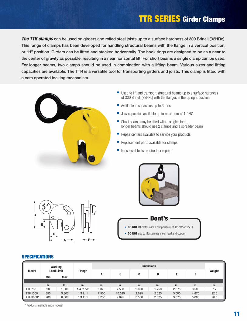
Available in capacities up to 10 tons
Available jaw width up to 12"
Shackle furnished for quick and easy component attachment
Available in single or double clamps
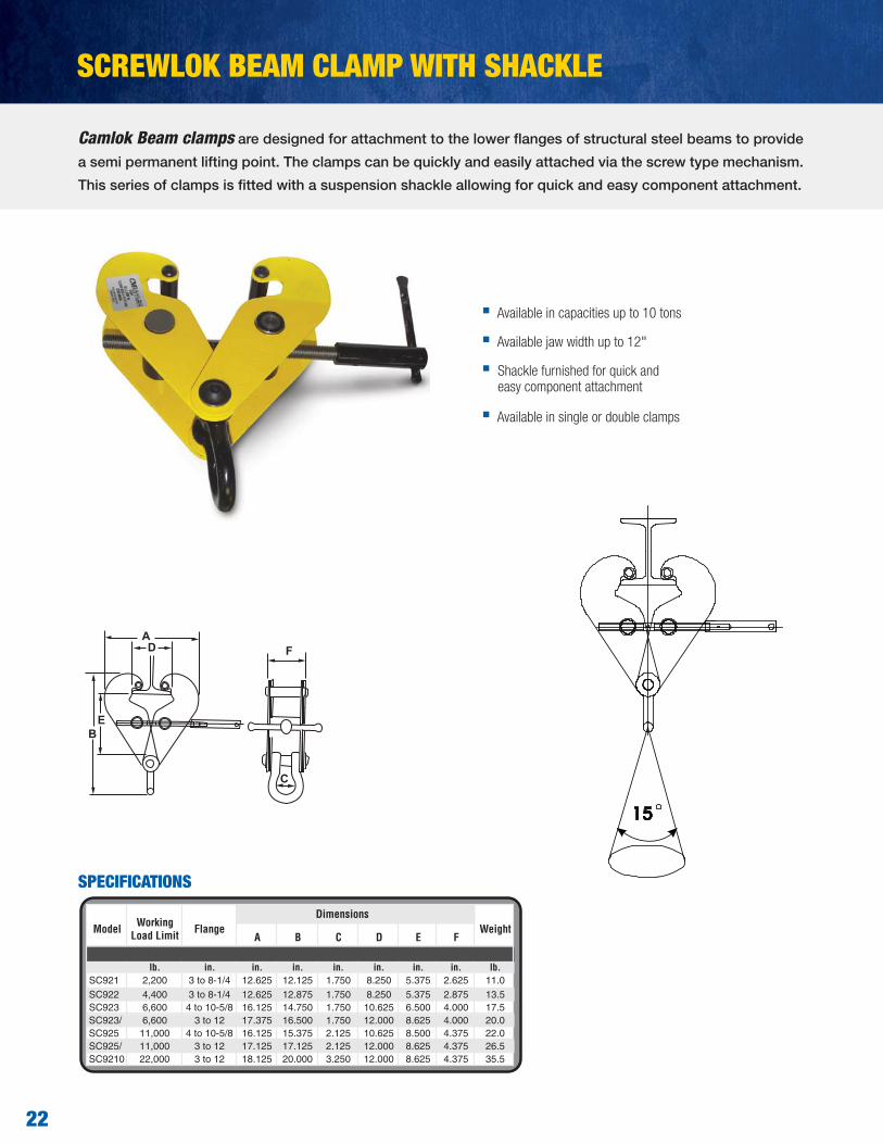
A B C D E F
lb. in. in. in. in. in. in. in. lb.SC921 2,200 3 to 8-1/4 12.625 12.125 1.750 8.250 5.375 2.625 11.0SC922 4,400 3 to 8-1/4 12.625 12.875 1.750 8.250 5.375 2.875 13.5SC923 6,600 4 to 10-5/8 16.125 14.750 1.750 10.625 6.500 4.000 17.5SC923/ 6,600 3 to 12 17.375 16.500 1.750 12.000 8.625 4.000 20.0SC925 11,000 4 to 10-5/8 16.125 15.375 2.125 10.625 8.500 4.375 22.0SC925/ 11,000 3 to 12 17.125 17.125 2.125 12.000 8.625 4.375 26.5SC9210 22,000 3 to 12 18.125 20.000 3.250 12.000 8.625 4.375 35.5
WeightModel Working Load Limit Flange
Dimensions
EB
AD F
C
SCREWLOK BEAM CLAMP WITH SHACKLE
SPECIFICATIONS
Camlok Beam clamps are designed for attachment to the lower flanges of structural steel beams to provide
a semi permanent lifting point. The clamps can be quickly and easily attached via the screw type mechanism.
This series of clamps is fitted with a suspension shackle allowing for quick and easy component attachment.

23
Minimum Maximum
lb. in. in. lb.SC922T 4,400 2.995 8.387 28.7SC923T 6,600 3.994 10.783 35.3
SC923/LT 6,600 2.995 12.181 44.1SC925/T 11,000 3.994 10.783 50.7
SC925/LT* 11,000 2.995 12.181 59.5
WeightModel
Flange WidthWorkingLoad Limit
Available in capacities up to 5 tons
Available to fit flanges up to 12.181"
The SC Series Twin Beam clamps enable one beam to be suspended beneath another. The clamps quickly
and easily attach to the beams using the screw type mechanizm. These clamps should be used for supporting
vertical loads only.
SC SERIES TWIN BEAM CLAMP
SPECIFICATIONS

24
CLB SERIES Lifting Lugs
Spring loaded bolt to prevent accidental release
Mounted at the side of the container in either upper or lower holes
Easy installation and removal, simple insert and turn installation
Designed to eliminate the dangerous use of standard hooks
Lugs cannot drop out when slings become slack
Lugs can be used left hand or right hand turns
For maximum capacity use a lifting beam in conjunction with the CLB lifting lugs
A B C D E F G
lb. in. in. in. in. in. in. lb.CLB32 70,500 5.984 7.126 1.772 1.457 2.874 2.953 1.575 39.7CLB40 88,100 5.984 7.126 1.772 1.457 2.874 2.953 1.575 39.7
Imperial
WeightDimensions
ModelWorking Load
Limit(Per set of 4)
in.
The CLB container lugs are supplied in sets of four. They are available with a total capacity of 56 tons. The
CLB series serve as flexible lashing points for the transportation of containers. The CLB lugs are mounted
horizontally to the side of the container at either the top or bottom fixing holes. This model has a spring loaded
bolt to prevent accidental release.
E
A F
B
C
D
G
20
SPECIFICATIONS
40T40T
32T
36º
50º
50TVertical
Angle of lift must be specified when ordering CLB lifting lugs
REDUCTION OF WORKING LOAD LIMIT
Designed to eliminate the use of standard hooks as attachments.
CLB DESIGN

25
CLB SAFETY INFORMATION
DO NOT USE
1. Spreader beam adds stability to lift.
2. CLB lugs can be used in the top fitting also.
3. Un-symmetrically loaded containers can be handled by using lifting beams and shortening chain slings.
1. Bottom side 2. Top side 3. Bottom end
For maximum load capacity a lifting frame can be used with the lugs attached as above.
NOTE: Minimum angle will depend on W.L.L. Required
FOR FURTHER INFORMATION CONTACT CUSTOMER SERVICE AT 800-888-0985
XXXXXXXXXXXXXXXXXXXXXXXXXXXXXXXXXXXXXXXXXXXXXXXXXXXXXXXXXXXXXXXXXXXXXXXXXXXXXXXXXXXXXX XXXXXXXXXXXXXXXXXXXXXXXXXXXXXXXXXXXXXXXXXXXXXXXX XXXXXXXXXXXXXXXXXXXXXXXXXXXXXXXXXXXXXXXXXXXXXXXXXXXXXXXXXXXXXXXXXXXXXXXXXXXXXXXXXXXXXXXXXXXXXXXXXXXXXXXXXXXXXXXXXXXXXXXXXXXXXXXXXXXXXXLifting frames offer little stability.
NOT recommended, sling may damage container.

26
CAMLOK SPARE PARTS
‘92 SERIES - VERTICAL PLATE LIFTING CLAMPSNo special tools are required to repair clamps. Heat may be required to release the bonding compound on some screws.
After repair use STUDLOCK on all screws removed.
Always quote clamp serial number, part description and model when ordering spares.
CZ - VERTICAL PLATE LIFTING CLAMPSNo special tools are required to repair clamps. Heat may be required to release the bonding compound on some screws.
After repair use STUDLOCK on all screws removed.
Always quote clamp serial number, part description and model when ordering spares.
Reference Description
10 Shell welded assembly
20 Internal assembly
27 Spring
31 Hook ring
32 Hook ring pin
40 Cam assembly and lever
41 Cam
47 Locking lever and pin
50 Pad assembly
60 Jaw bolt assembly
ONLY USE GENUINE CAMLOK SPARE PARTS
31
32
50
4140
47 10
16
20
27
17
10
31
32
50
4140
47
10 20
27
60
Reference Description
10 Shell plates (set of 4)
16 Shell pins (set of 3)
17 Shell screws (6 off)
20 Internal assembly
27 Spring
31 Hook ring
32 Hook ring pin
40 Cam assembly
41 Cam
47 Locking lever and pin
50 Pad assembly
ONLY USE GENUINE CAMLOK SPARE PARTS

27
CY - “HINGED” VERTICAL PLATE CLAMPSNo special tools are required to repair clamps. Heat may be required to release the bonding compound on some screws.
After repair use STUDLOCK on all screws removed.
Always quote clamp serial number, part description and model when ordering spares.
CX - “HINGED” VERTICAL PLATE CLAMPSNo special tools are required to repair clamps. Heat may be required to release the bonding compound on some screws.
After repair use STUDLOCK on all screws removed.
Always quote clamp serial number, part description and model when ordering spares.
Reference Description
10 Shell plates (set of 4)
16 Shell pins (2 each)
17 Shell screws (set of 4)
20 Internal assembly
27 Spring
32 Hook ring pin
34 Hook ring fork
35 Swivel hook ring
37 Eye bolt and nut
40 Cam assembly
41 Cam
47 Locking lever and pin
50 Pad Assembly
60 Jaw bolt assembly
Reference Description
10 Shell welded assembly
20 Internal assembly
27 Spring
32 Hook ring pin
34 Hook ring fork
35 Eye cam
37 Eye bolt and nut
40 Cam assembly
41 Cam
47 Locking lever and pin
50 Pad assembly
60 Jaw bolt assembly
35
32
50
4140
4760
16
20
27
17
10
3437
35
32
50
4140
47 60 20
27
10
3437
CAMLOK SPARE PARTS
ONLY USE GENUINE CAMLOK SPARE PARTS
ONLY USE GENUINE CAMLOK SPARE PARTS

In addition to the strong knowledge base exemplified by comprehensive training programs, Columbus McKinnon is one of the only manufacturers supplying complete lifting systems to satisfy unique material handling requirements of users in a variety of environments. From jib cranes and hoists to chain slings, clamps, and related attachments; systems include products that are matched specifically to the lifting needs of the application. Products may also be modified in order to ensure that the proper system is in place for the job.
Whether your needs call for a single Camlok clamp or a completely engineered system to outfit your production facility, Columbus McKinnon provides the products and expertise to keep your workforce productive and safe.
Phone (800) 888.0985 Fax: (716) 689.5644 www.cmworks.com © 2013 Columbus McKinnon Corporation. All Rights Reserved. Stock #CMR-CAMLOK-1213 EP 1000 BB
KNOW HOW...KNOW WHY Columbus McKinnon is a global leader in providing expertise and training in the proper use and inspection of rigging and overhead lifting equipment. With a range of comprehensive programs and seminars conducted at venues throughout North America, as well as on site at private companies and industries, Columbus McKinnon courses include:
Hoist Maintenance RiggingLoad Securement Safe HoistingCrane & Hoist Inspection Crane Operator TrainingRigging Gear Inspection
Classes are available at our Niagara Training Center and the state-of-the-art Hoist & Rigging Training Center of Excellence in the Center for Occupational Health and Automobile Manufacturing (COHAM) lab at The Ohio State University. The COHAM lab is a hands-on learning center which allows attendees to understand how to properly use and inspect overhead lifting equipment. This leading-edge training program is designed to increase workplace productivity and safety in a ergonomically friendly environment.