Camera Recti cation1 - University of Aucklandrklette/TeachAuckland...Recti cation Stereo Vision...
28
Rectification Stereo Vision Camera Rectification 1 Lecture 16 See Sections 6.3 and 7.3 in Reinhard Klette: Concise Computer Vision Springer-Verlag, London, 2014 ccv.wordpress.fos.auckland.ac.nz 1 See last slide for copyright information. 1 / 28
-
Upload
truongkhanh -
Category
Documents
-
view
214 -
download
1
Transcript of Camera Recti cation1 - University of Aucklandrklette/TeachAuckland...Recti cation Stereo Vision...
Rectification Stereo Vision
Camera Rectification1
Lecture 16
See Sections 6.3 and 7.3 inReinhard Klette: Concise Computer Vision
Springer-Verlag, London, 2014
ccv.wordpress.fos.auckland.ac.nz
1See last slide for copyright information.1 / 28

Rectification Stereo Vision
Agenda
1 Rectification of Stereo Image Pairs
2 Stereo Vision
2 / 28

Rectification Stereo Vision
Mapping into Canonical Stereo Geometry
Warp recorded image pairs such that it appears that they are recordedin canonical stereo geometry (CSG) by a pair of identical cameras
Optic axis of left camera Optic axis of right camera
P=(X,Y,Z)
Row y Row y
Left image Right image
Base distance b
xuL xuR
This process is called geometric rectification; it can be done by usingintrinsic and extrinsic parameters as obtained by camera calibration
3 / 28

Rectification Stereo Vision
Example 1: Two “non-CSG” Input Images
Recorded pair of images before and after rectificationRecording: b ≈ 10 m, different viewing directions, definitely not CSG
4 / 28

Rectification Stereo Vision
Example 2: Trinocular “CSG-Recording”
Three cameras installed with goal to match canonical stereo geometryBase distances: left to middle: ≈40 cm, middle to right: ≈30 cm
Rectified middle view shows on the left barrel transform correction5 / 28

Rectification Stereo Vision
Multi-Camera System
We do not restrict the discussion to just a left camera and a right camera
Consider general case of a Camera i or Camera j , where numbers i and jidentify different cameras in a multi-camera system
The Camera Matrix (for Camera i)
Defined by (examples of) intrinsic camera parameters
1. edge lengths exi and eyi of camera sensor cells (defining the aspectratio)
2. skew parameter si
3. coordinates of the principal point ci = (cxi , c
yi ) where the optical axis
of Camera i and image plane intersect
4. the focal length fi
6 / 28

Rectification Stereo Vision
Used Camera Model
We have a refined projection equation in 4D homogeneous coordinates,mapping a 3D point P = (Xw ,Yw ,Zw ) into the image coordinatespi = (xi , yi ) of the ith camera as follows:
k
xiyi1
=
fi/exi si cxi 0
0 fi/eyi cyi 0
0 0 1 0
[ Ri −R>i ti
0> 1
]Xw
Yw
Zw
1
= [Ki |0] · Ai · [Xw ,Yw ,Zw , 1]>
where Ri and ti denote the rotation matrix and translation vector in 3Dinhomogeneous world coordinates, and k 6= 0 is a scaling factor
7 / 28

Rectification Stereo Vision
Three Matrices
Equation on Page 7 defines
3×3 matrix Ki of intrinsic camera parameters
4×4 matrix Ai of extrinsic parameters (of affine transform) of Camera i
The 3×4 camera matrixCi = [Ki |0] · Ai
is defined by 11 parameters if we allow for an arbitrary scaling ofparameters; otherwise, it is 12
8 / 28

Rectification Stereo Vision
Common Viewing Direction
Illustration for calculating common viewing direction for Cameras i and j
9 / 28

Rectification Stereo Vision
Common Viewing Direction for Rectifying Cameras i and j
Identify a common viewing direction for Cameras i and j , replacing thegiven viewing directions along the optical axes of those two cameras
Let Π be a plane perpendicular to the baseline vector bij from theprojection centre of Camera i to the projection centre of Camera j
Project the unit vectors z◦i and z◦j of both optical axes into Π, whichresults in vectors ni and nj , respectively
Algebraic relations are as follows:
ni =(bij × z◦i
)× bij and nj =
(bij × z◦j
)× bij
Could also use bji in both equations, but then uniformly four times
10 / 28

Rectification Stereo Vision
Final Formula for Common Direction
Use bisector of ni and nj for defining the unit vector
z◦ij =ni + nj
‖ni + nj‖2
of the common direction
Consider unit vector x◦ij in the same direction as bij
x◦ij =bij
‖bij‖2
Unit vector y◦ij defined by the constraint of ensuring (say) a left-hand 3DCartesian coordinate system
y◦ij = zij × x◦ij = −x◦ij × zij
Note: for any vectors a and b, (a,b, a× b) defines a left-hand tripod11 / 28

Rectification Stereo Vision
Modification of Images
The two images of Camera i and Camera j need to be modified as thoughboth would have been taken in the direction Rij = (xijyijzij)
>, instead ofthe actually used directions Ri and Rj
Producing the Rectified Image Pair
Rotation matrices that rotate both cameras into their new (virtual)viewing direction are as follows:
R∗i = RijR>i and R∗j = RijR
>j
12 / 28
Rectification Stereo Vision
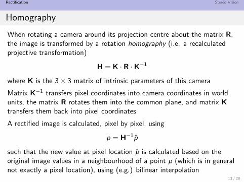
Homography
When rotating a camera around its projection centre about the matrix R,the image is transformed by a rotation homography (i.e. a recalculatedprojective transformation)
H = K · R ·K−1
where K is the 3× 3 matrix of intrinsic parameters of this camera
Matrix K−1 transfers pixel coordinates into camera coordinates in worldunits, the matrix R rotates them into the common plane, and matrix Ktransfers them back into pixel coordinates
A rectified image is calculated, pixel by pixel, using
p = H−1p̂
such that the new value at pixel location p̂ is calculated based on theoriginal image values in a neighbourhood of a point p (which is in generalnot exactly a pixel location), using (e.g.) bilinear interpolation
13 / 28

Rectification Stereo Vision
Creating an Identical Twin
We want to have the image of Camera j after rotation homography withrespect to the parameters of Camera i , i.e. we create an identical copy ofCamera i at the pose of Camera jFor this, apply the rotation homography
Hij = Ki · R∗j ·K−1j
which
1 first transforms by K−1j the points in the jth image plane into a
“normalized” coordinate system
2 then we apply R∗j to perform the desired rotation
3 finally, Ki for transforming the rotation result according to theparameters of Camera i
14 / 28
Rectification Stereo Vision
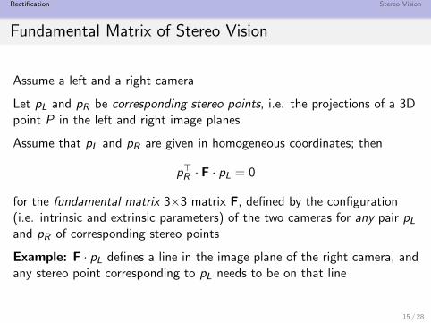
Fundamental Matrix of Stereo Vision
Assume a left and a right camera
Let pL and pR be corresponding stereo points, i.e. the projections of a 3Dpoint P in the left and right image planes
Assume that pL and pR are given in homogeneous coordinates; then
p>R · F · pL = 0
for the fundamental matrix 3×3 matrix F, defined by the configuration(i.e. intrinsic and extrinsic parameters) of the two cameras for any pair pL
and pR of corresponding stereo points
Example: F · pL defines a line in the image plane of the right camera, andany stereo point corresponding to pL needs to be on that line
15 / 28
Rectification Stereo Vision
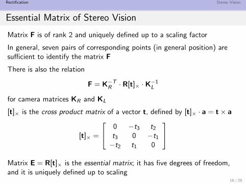
Essential Matrix of Stereo Vision
Matrix F is of rank 2 and uniquely defined up to a scaling factor
In general, seven pairs of corresponding points (in general position) aresufficient to identify the matrix F
There is also the relation
F = K−TR · R[t]× ·K−1L
for camera matrices KR and KL
[t]× is the cross product matrix of a vector t, defined by [t]× · a = t× a
[t]× =
0 −t3 t2
t3 0 −t1
−t2 t1 0
Matrix E = R[t]× is the essential matrix; it has five degrees of freedom,and it is uniquely defined up to scaling
16 / 28

Rectification Stereo Vision
Agenda
1 Rectification of Stereo Image Pairs
2 Stereo Vision
17 / 28
Rectification Stereo Vision
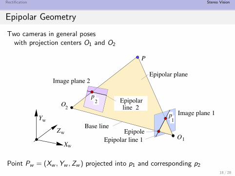
Epipolar Geometry
Two cameras in general poseswith projection centers O1 and O2
Zw
Yw
Xw
P
O
O2
1
Epipolar planeImage plane 2
Image plane 1
Epipolarline 2
Epipolar line 1
Base line
2
p
p
Epipole
1
Point Pw = (Xw ,Yw ,Zw ) projected into p1 and corresponding p2
18 / 28

Rectification Stereo Vision
Simplifying the Task of Stereo Correspondence Analysis
Starting at point p1 in Image 1,find the corresponding point p2 in Image 2
Three non-collinear points in 3D space define a plane
Points O1, O2 and point p1 define an epipolar plane
Epipolar line = intersection of an image plane with an epipolar plane
Observation
Search for point p2 can proceed along the epipolar line in Image 2
19 / 28

Rectification Stereo Vision
Canonical Epipolar Geometry
Given: Canonical stereo geometry with a left and a right camera
Visible 3D point P defines an epipolar plane which intersects both imageplanes in the same row
Epipolar Line = Same Image Row
In undistorted coordinates: Start at p1 = (xu, yu) in one camera, searchfor corresponding point in image row yu in the other camera
In image coordinates: E.g., start at a pixel pL = (xL, y) in the leftimage, search for corresponding pixel pR = (xR , y) in the right image
In this case: xR ≤ xL
20 / 28
Rectification Stereo Vision
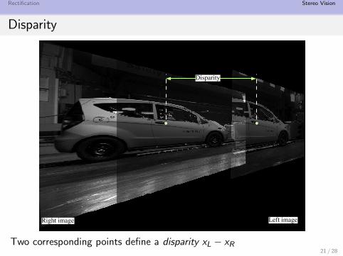
Disparity
Right image Left image
Disparity
Two corresponding points define a disparity xL − xR21 / 28

Rectification Stereo Vision
xL ≥ xR
A stereo pair recorded in the early 1990s with the goal to ensure CSG:
p pq
Corresponding point q to a point p in left imageis left of this point in the right image
22 / 28

Rectification Stereo Vision
Triangulation for Canonical Stereo Geometry
Now: We have all together for going from stereo-image input data torecovered 3D points P = (Xs ,Ys ,Zs) in camera coordinates
Have: Base distance b > 0 and unified focal length f
Central projection equations for left and right camera
puL = (xuL, yu) = (f · Xs
Zs,
f · Ys
Zs)
puR = (xuR , yu) = (f · (Xs − b)
Zs,
f · Ys
Zs)
23 / 28

Rectification Stereo Vision
The Triangle
24 / 28

Rectification Stereo Vision
Solution
Eliminate Zs from both equations
Zs =f · Xs
xuL=
f · (Xs − b)
xuR
Solve for Xs
Xs =b · xuL
xuL − xuR
By using Xs we also obtain
Zs =b · f
xuL − xuR
By using Zs we also derive that
Ys =b · yu
xuL − xuR
with yu = yuL = yuR25 / 28
Rectification Stereo Vision
Summary
Observation
Two corresponding pixels (xL, y) = (xuL + cxL, yu + cyL) and(xR , y) = (xuR + cxR , yu + cyR)
identify its joint pre-image P = (Xs ,Ys ,Zs) in 3D space using thetriangulation formulas on the page before
Examples
Disparity xuL − xuR = 0 then pre-image P = (Xs ,Ys ,Zs) is “at infinity”
The larger the disparity xuL − xuR the closer is P to the cameras
Integer coordinates in images, thus integer disparities xuL − xuR as well
26 / 28
Rectification Stereo Vision
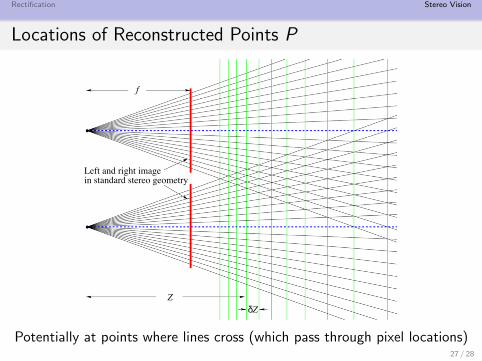
Locations of Reconstructed Points P
f
Left and right imagein standard stereo geometry
ZδZ
Potentially at points where lines cross (which pass through pixel locations)27 / 28
Rectification Stereo Vision
Copyright Information
This slide show was prepared by Reinhard Klettewith kind permission from Springer Science+Business Media B.V.
The slide show can be used freely for presentations.However, all the material is copyrighted.
R. Klette. Concise Computer Vision.c©Springer-Verlag, London, 2014.
In case of citation: just cite the book, that’s fine.
28 / 28