CAMERA CONTROL UNIT CCU-900 CCU-900P ... CONTROL UNIT CCU-900 CCU-900P DIGITAL INTERFACE UNIT...
58
CAMERA CONTROL UNIT CCU-900 CCU-900P DIGITAL INTERFACE UNIT BKP-9330 INSTALLATION AND MAINTENANCE MANUAL 1st Edition (Revised 2) Serial No. 10001 and Higher: CCU-900 (UC) Serial No. 30001 and Higher: CCU-900 (J) Serial No. 40001 and Higher: CCU-900P (CE) Serial No. 10001 and Higher: BKP-9330 (SY)
Transcript of CAMERA CONTROL UNIT CCU-900 CCU-900P ... CONTROL UNIT CCU-900 CCU-900P DIGITAL INTERFACE UNIT...
CAMERA CONTROL UNIT
CCU-900CCU-900PDIGITAL INTERFACE UNITBKP-9330
INSTALLATION AND MAINTENANCE MANUAL1st Edition (Revised 2)Serial No. 10001 and Higher: CCU-900 (UC)Serial No. 30001 and Higher: CCU-900 (J)Serial No. 40001 and Higher: CCU-900P (CE)Serial No. 10001 and Higher: BKP-9330 (SY)
CCU-900/900P IMM
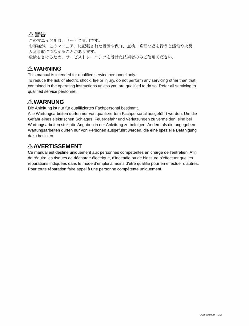
! WARNINGThis manual is intended for qualified service personnel only.To reduce the risk of electric shock, fire or injury, do not perform any servicing other than thatcontained in the operating instructions unless you are qualified to do so. Refer all servicing toqualified service personnel.
! WARNUNGDie Anleitung ist nur für qualifiziertes Fachpersonal bestimmt.Alle Wartungsarbeiten dürfen nur von qualifiziertem Fachpersonal ausgeführt werden. Um dieGefahr eines elektrischen Schlages, Feuergefahr und Verletzungen zu vermeiden, sind beiWartungsarbeiten strikt die Angaben in der Anleitung zu befolgen. Andere als die angegebenWartungsarbeiten dürfen nur von Personen ausgeführt werden, die eine spezielle Befähigungdazu besitzen.
! AVERTISSEMENTCe manual est destiné uniquement aux personnes compétentes en charge de l’entretien. Afinde réduire les risques de décharge électrique, d’incendie ou de blessure n’effectuer que lesréparations indiquées dans le mode d’emploi à moins d’être qualifié pour en effectuer d’autres.Pour toute réparation faire appel à une personne compétente uniquement.
CCU-900/900P IMM
CLASS 1LASER PRODUCT
LASER KLASSE 1PRODUKT
This camera control unit is classified as a CLASS 1LASER PRODUCT.The CLASS 1 LASER PRODUCT label is located on therear panel.
Laser Diode PropertiesMaterial : In GaAsPWave length : 1310 nmEmission duration : Pulse code modulationLaser output power: _8 dBm
SAFETY CHECK-OUT
After correcting the original service problem,perform the following safety checks beforereleasing the set to the customer :
Check the metal trim, “metallized” knobs, screws,and all other exposed metal parts for ACleakage. Check leakage as described below.
LEAKAGE TEST
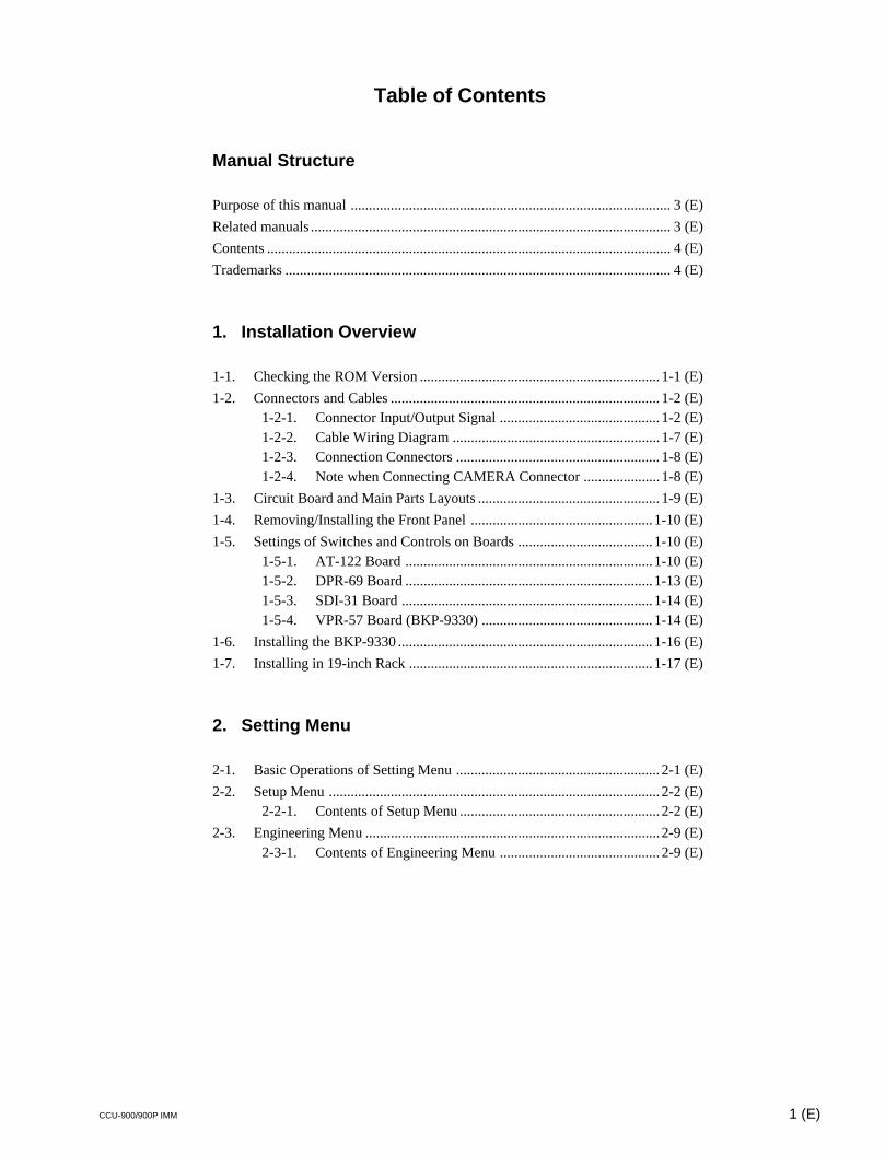
The AC leakage from any exposed metal part toearth ground and from all exposed metal parts toany exposed metal part having a return tochassis, must not exceed 3.5 mA. Leakagecurrent can be measured by any one of threemethods.
1. A commercial leakage tester, such as theSimpson 229 or RCA WT-540A. Follow themanufacturers’ instructions to use theseinstruments.
2. A battery-operated AC milliammeter. TheData Precision 245 digital multimeter issuitable for this job.
3. Measuring the voltage drop across a resistorby means of a VOM or battery-operated ACvoltmeter. The “limit” indication is 5.25 V, soanalog meters must have an accurate low-voltage scale. The Simpson 250 and SanwaSH-63Trd are examples of a passive VOMthat is suitable. Nearly all battery operateddigital multimeters that have a 20 V AC rangeare suitable. (See Fig. A)
To Exposed MetalParts on Set
Fig A. Using an AC voltmeter to check AC leakage.
ACvoltmeter(5.25V)
Earth Ground
0.15 µF 1.5 kZ
nThe cautions on this page are applied to CCU-900/900P.
1 (P)

1 (E)CCU-900/900P IMM
Table of Contents
Manual Structure
Purpose of this manual ........................................................................................ 3 (E)
Related manuals ................................................................................................... 3 (E)
Contents ............................................................................................................... 4 (E)
Trademarks .......................................................................................................... 4 (E)
1. Installation Overview
1-1. Checking the ROM Version .................................................................. 1-1 (E)
1-2. Connectors and Cables .......................................................................... 1-2 (E)1-2-1. Connector Input/Output Signal ............................................ 1-2 (E)1-2-2. Cable Wiring Diagram ......................................................... 1-7 (E)1-2-3. Connection Connectors ........................................................ 1-8 (E)1-2-4. Note when Connecting CAMERA Connector ..................... 1-8 (E)
1-3. Circuit Board and Main Parts Layouts .................................................. 1-9 (E)
1-4. Removing/Installing the Front Panel .................................................. 1-10 (E)
1-5. Settings of Switches and Controls on Boards .....................................1-10 (E)1-5-1. AT-122 Board .................................................................... 1-10 (E)1-5-2. DPR-69 Board .................................................................... 1-13 (E)1-5-3. SDI-31 Board ..................................................................... 1-14 (E)1-5-4. VPR-57 Board (BKP-9330) ............................................... 1-14 (E)
1-6. Installing the BKP-9330 ...................................................................... 1-16 (E)
1-7. Installing in 19-inch Rack ...................................................................1-17 (E)
2. Setting Menu
2-1. Basic Operations of Setting Menu ........................................................ 2-1 (E)
2-2. Setup Menu ........................................................................................... 2-2 (E)2-2-1. Contents of Setup Menu ....................................................... 2-2 (E)
2-3. Engineering Menu ................................................................................. 2-9 (E)2-3-1. Contents of Engineering Menu ............................................ 2-9 (E)
2 (E) CCU-900/900P IMM
3. System Setup
3-1. Audio System ........................................................................................ 3-1 (E)3-1-1. Setting the Intercom System ................................................ 3-1 (E)3-1-2. Setting the Microphone ........................................................ 3-3 (E)
3-2. Systems .................................................................................................3-4 (E)3-2-1. Setting the Tally System ...................................................... 3-4 (E)3-2-2. Setting the Camera Number ................................................. 3-4 (E)
3-3. Video Signal System ............................................................................. 3-5 (E)3-3-1. Selecting the Input/Output Signal ........................................ 3-5 (E)3-3-2. Resetting the Control Data ................................................... 3-5 (E)3-3-3. Adjusting the Signal Phase ................................................... 3-5 (E)3-3-4. Adjusting the Level of Signals for Waveform Monitor ....... 3-7 (E)3-3-5. Adjusting the Level of Signals for Picture Monitor ............. 3-9 (E)3-3-6. Setting the RETURN MATRIX ......................................... 3-10 (E)3-3-7. Setting the DUAL CAMERA MODE................................ 3-11 (E)3-3-8. Settings for the Signals of the Optional Boards ................. 3-13 (E)3-3-9. Mode Control Setting from the REMOTE Connector ....... 3-14 (E)
4. Service Overview
4-1. Cleaning of Connector/Cable ................................................................ 4-1 (E)
4-2. Recommended Replacement Parts ........................................................ 4-2 (E)4-2-1. DC Fans (Rear Panel) ........................................................... 4-2 (E)
3 (E)CCU-900/900P IMM
Purpose of this manualThis manual is the installation and maintenance manual of Camera Control UnitCCU-900/900P.This manual is intended for use by trained system and service engineers, anddescribes the information regarding the installation of the unit and the informationthat premises the service based on components replacement.
Related manualsBeside this Installation and Maintenance Manual, the following manuals are avail-able for the unit.
. Operation Manual (supplied with CCU-900/900P)This manual describes how to operate the CCU-900/900P.
. Maintenance Manual Vol. 1 (available on request)This manual intended for use by trained system and service engineers describes(the circuit overview, self-diagnosis, the main part replacements, electricalalignment, etc.) required for parts-level service.For obtaining, contact your local Sony Sales Office/Service Center.Part number: 9-968-569-0X
. Maintenance Manual Vol. 2 (available on request)This manual intended for use by trained system and service engineers describes(the parts list, semiconductor pin assignments, block diagrams, schematic dia-grams and board layouts) required for parts-level service.For obtaining, contact your local Sony Sales Office/Service Center.Part number: 9-968-570-0X
..... “Semiconductor Pin Assignments” CD-ROM (available on request)This “Semiconductor Pin Assignments” CD-ROM allows you to search forsemiconductors used in Communication System Solutions Network Companyequipment.Semiconductors that cannot be searched for on this CD-ROM are listed in themaintenance manual for the corresponding unit. The maintenance manual containsa complete list of all semiconductors and their ID Nos., and thus should be usedtogether with the CD-ROM.Part number: 9-968-546-XX
Manual Structure
4 (E) CCU-900/900P IMM
ContentsThe following is a summary of the sections of this manual.
Section 1 Installation OverviewDescribes how to checking the ROM version, connectors and cables, setting ofswitches and controls on boards, installing in 19-inch rack, etc.
Section 2 Setting MenuDescribes how to operate the setup menu and engineering menu.
Section 3 System SetupDescribes how to set and adjust when connecting the unit to the camera system.
Section 4 Service OverviewDescribes recommended replacement parts and how to cleaning connector/cables.
TrademarksTrademarks and registered trademarks used in this manual are follows.
. Clear-Com is a registered trademark of Clear-Com Intercom Systems.
. Accuride is a registered trademark of Accuride International Corporation.
1-1 (E)CCU-900/900P IMM
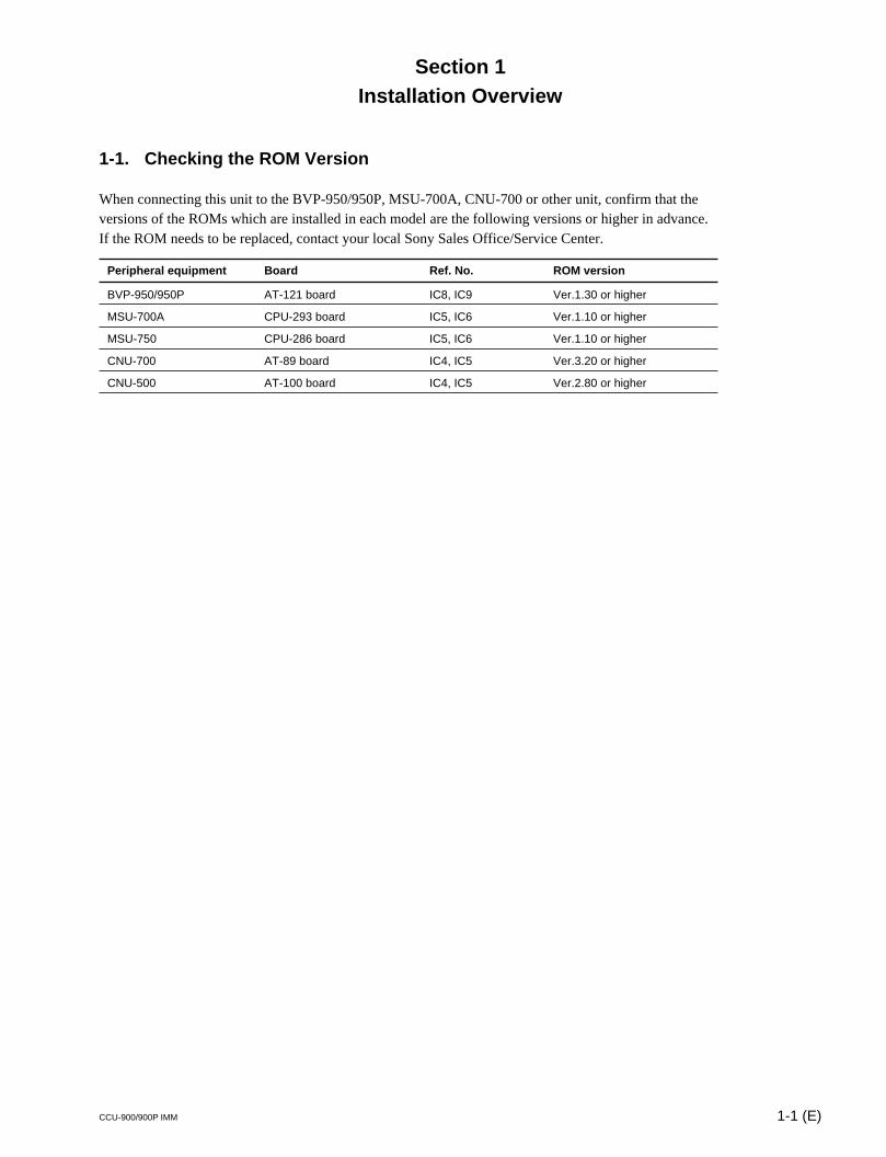
1-1. Checking the ROM Version
When connecting this unit to the BVP-950/950P, MSU-700A, CNU-700 or other unit, confirm that theversions of the ROMs which are installed in each model are the following versions or higher in advance.If the ROM needs to be replaced, contact your local Sony Sales Office/Service Center.
Peripheral equipment Board Ref. No. ROM version
BVP-950/950P AT-121 board IC8, IC9 Ver.1.30 or higher
MSU-700A CPU-293 board IC5, IC6 Ver.1.10 or higher
MSU-750 CPU-286 board IC5, IC6 Ver.1.10 or higher
CNU-700 AT-89 board IC4, IC5 Ver.3.20 or higher
CNU-500 AT-100 board IC4, IC5 Ver.2.80 or higher
Section 1Installation Overview
1-2 (E) CCU-900/900P IMM
1-2. Connectors and Cables
1-2-1. Connector Input/Output Signal
The connector input/output signals are as follows.
Rear panel
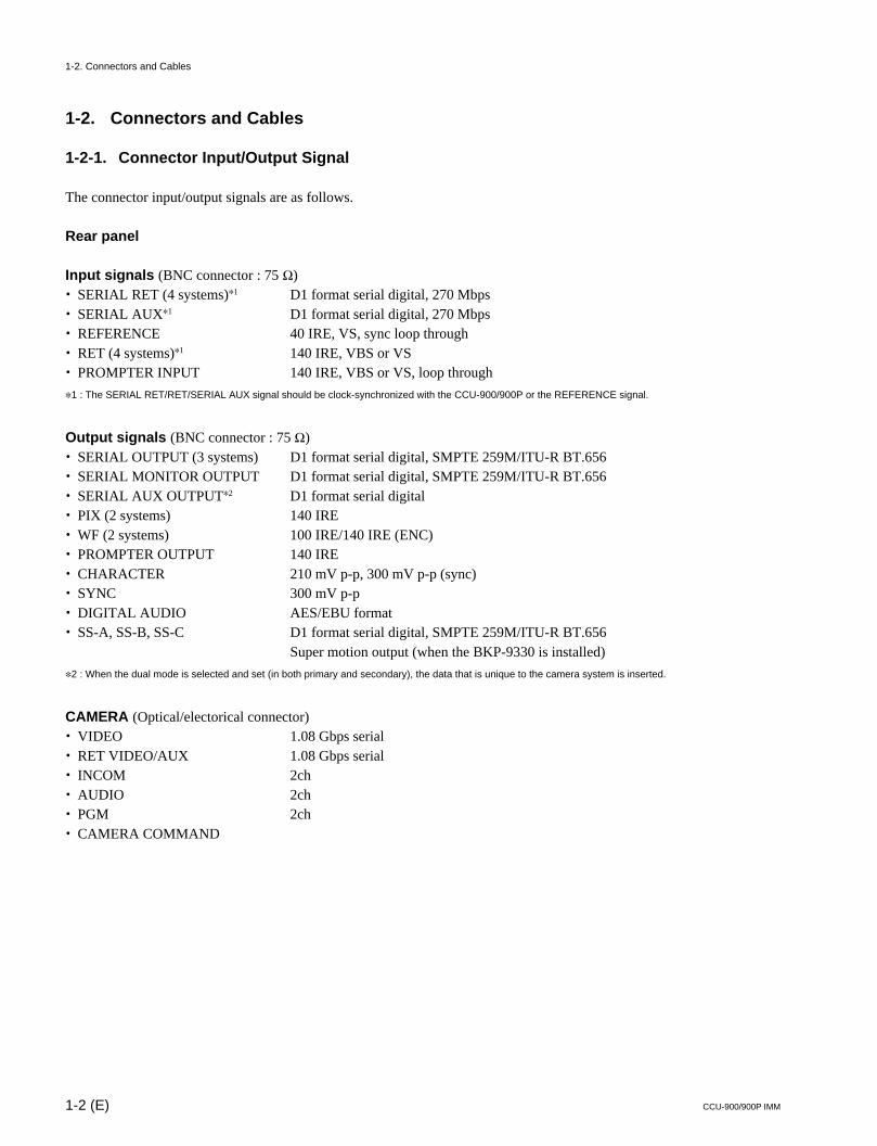
Input signals (BNC connector : 75 Z). SERIAL RET (4 systems)*1 D1 format serial digital, 270 Mbps. SERIAL AUX*1 D1 format serial digital, 270 Mbps. REFERENCE 40 IRE, VS, sync loop through. RET (4 systems)*1 140 IRE, VBS or VS. PROMPTER INPUT 140 IRE, VBS or VS, loop through
*1 : The SERIAL RET/RET/SERIAL AUX signal should be clock-synchronized with the CCU-900/900P or the REFERENCE signal.
Output signals (BNC connector : 75 Z). SERIAL OUTPUT (3 systems) D1 format serial digital, SMPTE 259M/ITU-R BT.656. SERIAL MONITOR OUTPUT D1 format serial digital, SMPTE 259M/ITU-R BT.656. SERIAL AUX OUTPUT*2 D1 format serial digital. PIX (2 systems) 140 IRE. WF (2 systems) 100 IRE/140 IRE (ENC). PROMPTER OUTPUT 140 IRE. CHARACTER 210 mV p-p, 300 mV p-p (sync). SYNC 300 mV p-p. DIGITAL AUDIO AES/EBU format. SS-A, SS-B, SS-C D1 format serial digital, SMPTE 259M/ITU-R BT.656
Super motion output (when the BKP-9330 is installed)
*2 : When the dual mode is selected and set (in both primary and secondary), the data that is unique to the camera system is inserted.
CAMERA (Optical/electorical connector). VIDEO 1.08 Gbps serial. RET VIDEO/AUX 1.08 Gbps serial. INCOM 2ch. AUDIO 2ch. PGM 2ch. CAMERA COMMAND
1-2. Connectors and Cables
1-3 (E)CCU-900/900P IMM
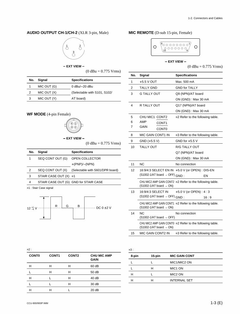
AUDIO OUTPUT CH-1/CH-2 (XLR 3-pin, Male)
_____ EXT VIEW _____
(0 dBu = 0.775 Vrms)
No. Signal Specifications
1 MIC OUT (G) 0 dBu/_20 dBu
2 MIC OUT (X) (Selectable with S101, S102/
3 MIC OUT (Y) AT board)
WF MODE (4-pin Female)
_____ EXT VIEW _____
(0 dBu = 0.775 Vrms)
No. Signal Specifications
1 SEQ CONT OUT (G) OPEN COLLECTOR
+(PNP)/_(NPN)
2 SEQ CONT OUT (X) (Selectable with S601/DPR board)
3 STAIR CASE OUT (X) *1
4 STAIR CASE OUT (G) GND for STAIR CASE
*1 : Stair Case signal
MIC REMOTE (D-sub 15-pin, Female)
_____ EXT VIEW _____
(0 dBu = 0.775 Vrms)
No. Signal Specifications
1 +5.5 V OUT Max. 500 mA
2 TALLY GND GND for TALLY
3 G TALLY OUT Q9 (NPN)/AT board
ON (GND) : Max 30 mA
4 R TALLY OUT Q17 (NPN)/AT board
ON (GND) : Max 30 mA
5 CHU MIC1 CONT2 *2 Refer to the following table.
6 AMP CONT17 GAIN
CONT0
8 MIC GAIN CONT1 IN *3 Refer to the following table.
9 GND (+5.5 V) GND for +5.5 V
10 TALLY OUT R/G TALLY OUT
Q7 (NPN)/AT board
ON (GND) : Max 30 mA
11 NC No connection
12 16:9/4:3 SELECT EN IN +5.0 V (or OPEN) : DIS-EN(S1002-1/AT board → OFF) GND : EN
CHU MIC2 AMP GAIN CONT2 *2 Refer to the following table.(S1002-1/AT board → ON)
13 16:9/4:3 SELECT IN +5.0 V (or OPEN) : 4 : 3(S1002-1/AT board → OFF) GND : 16 : 9
CHU MIC2 AMP GAIN CONT1 *2 Refer to the following table.(S1002-1/AT board → ON)
14 NC No connection(S1002-1/AT board → OFF)
CHU MIC2 AMP GAIN CONT0 *2 Refer to the following table.(S1002-1/AT board → ON)
15 MIC GAIN CONT2 IN *3 Refer to the following table.
*3 :
8-pin 15-pin MIC GAIN CONT
L L MIC1/MIC2 ON
L H MIC1 ON
H L MIC2 ON
H H INTERNAL SET
1 2
3
4 1
3 2
12 V+1_6
R G B DC 0 ±2 V
15 9
18
1-2. Connectors and Cables
*2 :
CONT0 CONT1 CONT2 CHU MIC AMPGAIN
H H H 60 dB
L H H 50 dB
H L H 40 dB
L L H 30 dB
H H L 20 dB
1-4 (E) CCU-900/900P IMM
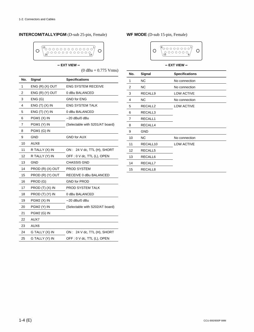
INTERCOM/TALLY/PGM (D-sub 25-pin, Female)
_____ EXT VIEW _____
(0 dBu = 0.775 Vrms)
No. Signal Specifications
1 ENG (R) (X) OUT ENG SYSTEM RECEIVE
2 ENG (R) (Y) OUT 0 dBu BALANCED
3 ENG (G) GND for ENG
4 ENG (T) (X) IN ENG SYSTEM TALK
5 ENG (T) (Y) IN 0 dBu BALANCED
6 PGM1 (X) IN _20 dBu/0 dBu
7 PGM1 (Y) IN (Selectable with S201/AT board)
8 PGM1 (G) IN
9 GND GND for AUX
10 AUX8
11 R TALLY (X) IN ON : 24 V dc, TTL (H), SHORT
12 R TALLY (Y) IN OFF : 0 V dc, TTL (L), OPEN
13 GND CHASSIS GND
14 PROD (R) (X) OUT PROD SYSTEM
15 PROD (R) (Y) OUT RECEIVE 0 dBu BALANCED
16 PROD (G) GND for PROD
17 PROD (T) (X) IN PROD SYSTEM TALK
18 PROD (T) (Y) IN 0 dBu BALANCED
19 PGM2 (X) IN _20 dBu/0 dBu
20 PGM2 (Y) IN (Selectable with S202/AT board)
21 PGM2 (G) IN
22 AUX7
23 AUX6
24 G TALLY (X) IN ON : 24 V dc, TTL (H), SHORT
25 G TALLY (Y) IN OFF : 0 V dc, TTL (L), OPEN
WF MODE (D-sub 15-pin, Female)
_____ EXT VIEW _____
No. Signal Specifications
1 NC No connection
2 NC No connection
3 RECALL9 LOW ACTIVE
4 NC No connection
5 RECALL2 LOW ACTIVE
6 RECALL3
7 RECALL1
8 RECALL4
9 GND
10 NC No connection
11 RECALL10 LOW ACTIVE
12 RECALL5
13 RECALL6
14 RECALL7
15 RECALL8
25 14
113
15 9
18
1-2. Connectors and Cables
1-5 (E)CCU-900/900P IMM
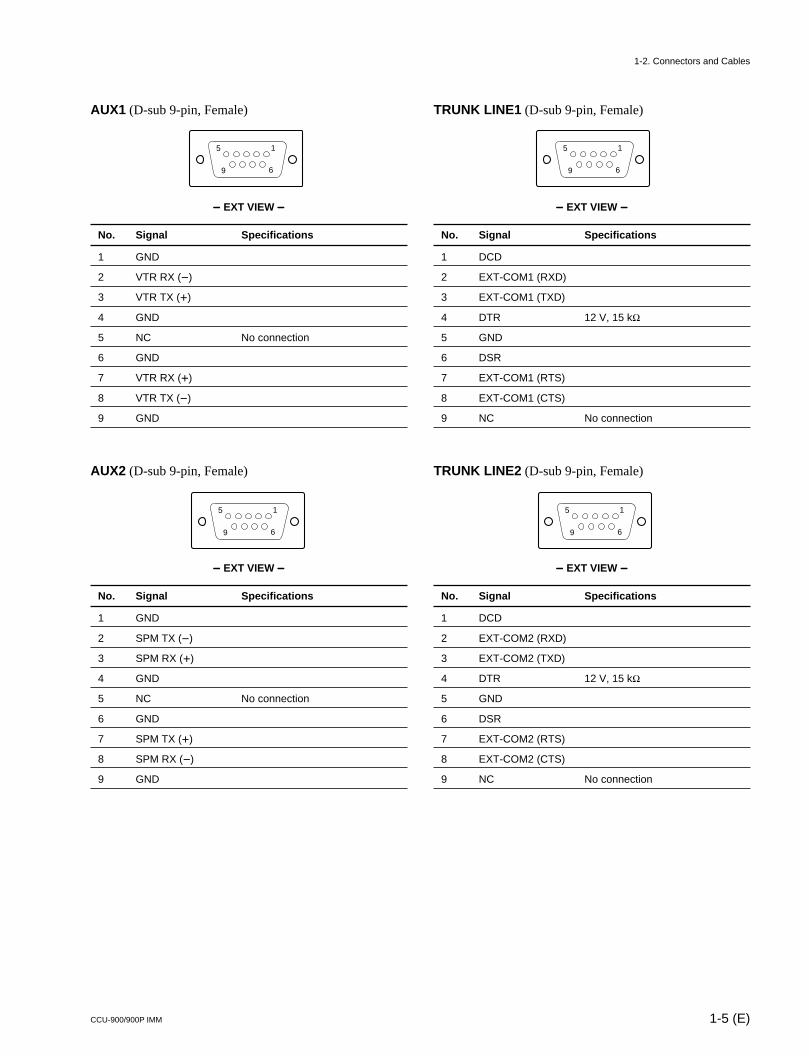
AUX1 (D-sub 9-pin, Female)
_____ EXT VIEW _____
No. Signal Specifications
1 GND
2 VTR RX (_)
3 VTR TX (+)
4 GND
5 NC No connection
6 GND
7 VTR RX (+)
8 VTR TX (_)
9 GND
AUX2 (D-sub 9-pin, Female)
_____ EXT VIEW _____
No. Signal Specifications
1 GND
2 SPM TX (_)
3 SPM RX (+)
4 GND
5 NC No connection
6 GND
7 SPM TX (+)
8 SPM RX (_)
9 GND
TRUNK LINE1 (D-sub 9-pin, Female)
_____ EXT VIEW _____
No. Signal Specifications
1 DCD
2 EXT-COM1 (RXD)
3 EXT-COM1 (TXD)
4 DTR 12 V, 15 kZ
5 GND
6 DSR
7 EXT-COM1 (RTS)
8 EXT-COM1 (CTS)
9 NC No connection
TRUNK LINE2 (D-sub 9-pin, Female)
_____ EXT VIEW _____
No. Signal Specifications
1 DCD
2 EXT-COM2 (RXD)
3 EXT-COM2 (TXD)
4 DTR 12 V, 15 kZ
5 GND
6 DSR
7 EXT-COM2 (RTS)
8 EXT-COM2 (CTS)
9 NC No connection
5
9 6
1
5
9 6
1
5
9 6
1
5
9 6
1
1-2. Connectors and Cables
1-6 (E) CCU-900/900P IMM
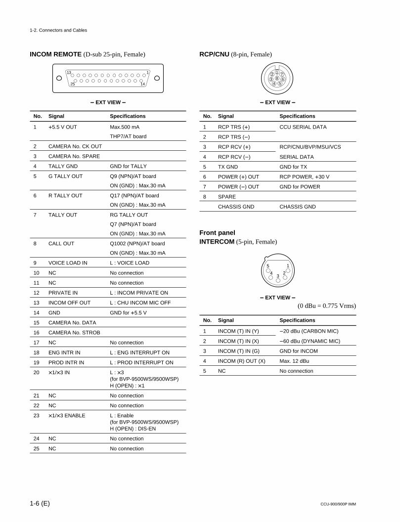
INCOM REMOTE (D-sub 25-pin, Female)
_____ EXT VIEW _____
No. Signal Specifications
1 +5.5 V OUT Max.500 mA
THP7/AT board
2 CAMERA No. CK OUT
3 CAMERA No. SPARE
4 TALLY GND GND for TALLY
5 G TALLY OUT Q9 (NPN)/AT board
ON (GND) : Max.30 mA
6 R TALLY OUT Q17 (NPN)/AT board
ON (GND) : Max.30 mA
7 TALLY OUT RG TALLY OUT
Q7 (NPN)/AT board
ON (GND) : Max.30 mA
8 CALL OUT Q1002 (NPN)/AT board
ON (GND) : Max.30 mA
9 VOICE LOAD IN L : VOICE LOAD
10 NC No connection
11 NC No connection
12 PRIVATE IN L : INCOM PRIVATE ON
13 INCOM OFF OUT L : CHU INCOM MIC OFF
14 GND GND for +5.5 V
15 CAMERA No. DATA
16 CAMERA No. STROB
17 NC No connection
18 ENG INTR IN L : ENG INTERRUPT ON
19 PROD INTR IN L : PROD INTERRUPT ON
20 x1/x3 IN L : x3(for BVP-9500WS/9500WSP)H (OPEN) : x1
21 NC No connection
22 NC No connection
23 x1/x3 ENABLE L : Enable(for BVP-9500WS/9500WSP)H (OPEN) : DIS-EN
24 NC No connection
25 NC No connection
RCP/CNU (8-pin, Female)
_____ EXT VIEW _____
No. Signal Specifications
1 RCP TRS (+) CCU SERIAL DATA
2 RCP TRS (_)
3 RCP RCV (+) RCP/CNU/BVP/MSU/VCS
4 RCP RCV (_) SERIAL DATA
5 TX GND GND for TX
6 POWER (+) OUT RCP POWER, +30 V
7 POWER (_) OUT GND for POWER
8 SPARE
CHASSIS GND CHASSIS GND
Front panelINTERCOM (5-pin, Female)
_____ EXT VIEW _____
(0 dBu = 0.775 Vrms)
No. Signal Specifications
1 INCOM (T) IN (Y) _20 dBu (CARBON MIC)
2 INCOM (T) IN (X) _60 dBu (DYNAMIC MIC)
3 INCOM (T) IN (G) GND for INCOM
4 INCOM (R) OUT (X) Max. 12 dBu
5 NC No connection
123
4 567
8
25 14
113
1
23
4
5
1-2. Connectors and Cables
1-7 (E)CCU-900/900P IMM
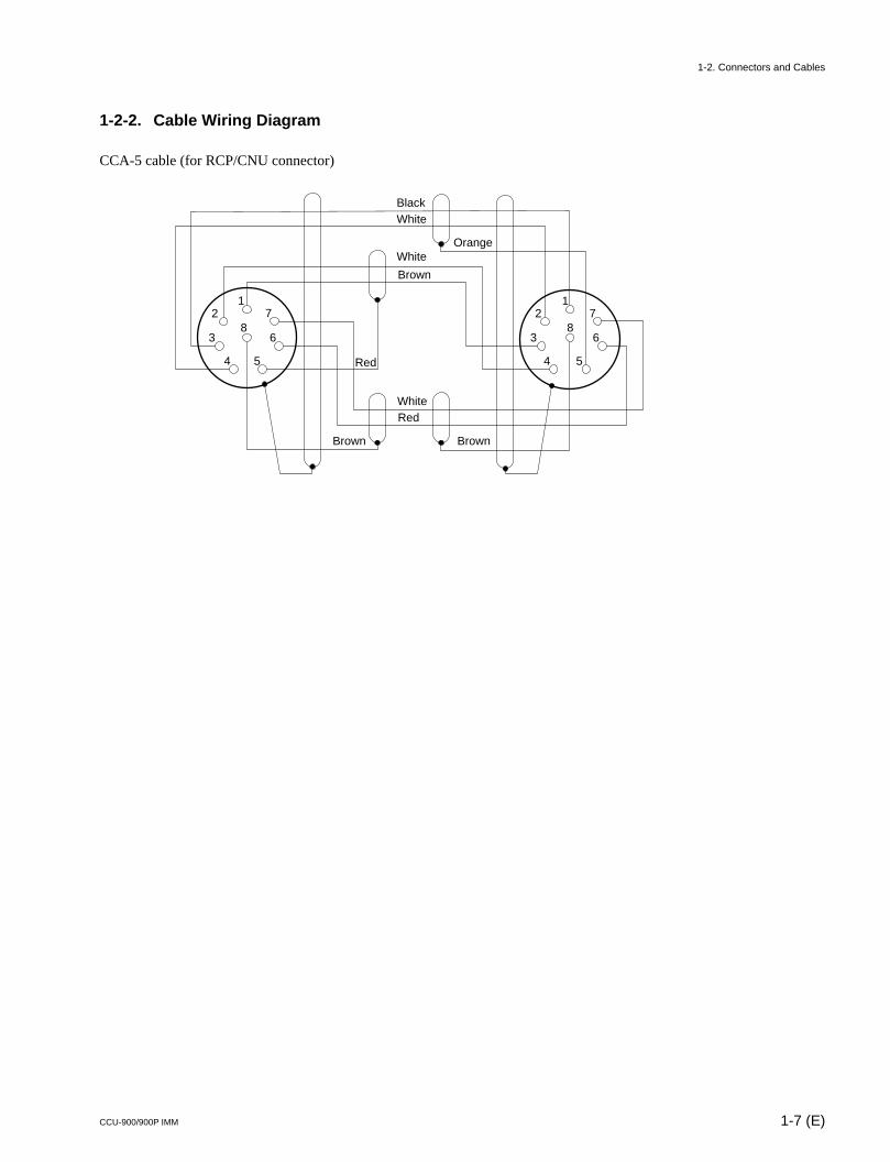
1-2-2. Cable Wiring Diagram
CCA-5 cable (for RCP/CNU connector)
BlackWhite
White
Brown
WhiteRed
Red
Brown Brown
Orange
12
3
4
8
5
6
71
2
3
4
8
5
6
7
1-2. Connectors and Cables
1-8 (E) CCU-900/900P IMM
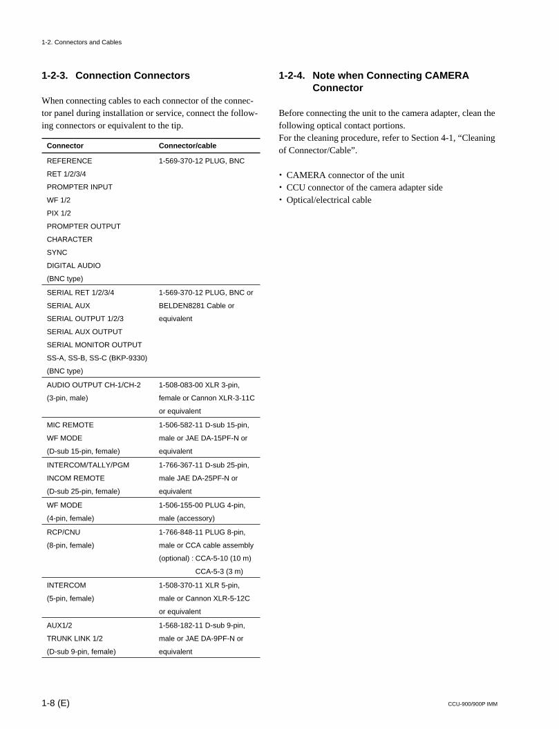
1-2-3. Connection Connectors
When connecting cables to each connector of the connec-tor panel during installation or service, connect the follow-ing connectors or equivalent to the tip.
Connector Connector/cable
REFERENCE 1-569-370-12 PLUG, BNC
RET 1/2/3/4
PROMPTER INPUT
WF 1/2
PIX 1/2
PROMPTER OUTPUT
CHARACTER
SYNC
DIGITAL AUDIO
(BNC type)
SERIAL RET 1/2/3/4 1-569-370-12 PLUG, BNC or
SERIAL AUX BELDEN8281 Cable or
SERIAL OUTPUT 1/2/3 equivalent
SERIAL AUX OUTPUT
SERIAL MONITOR OUTPUT
SS-A, SS-B, SS-C (BKP-9330)
(BNC type)
AUDIO OUTPUT CH-1/CH-2 1-508-083-00 XLR 3-pin,
(3-pin, male) female or Cannon XLR-3-11C
or equivalent
MIC REMOTE 1-506-582-11 D-sub 15-pin,
WF MODE male or JAE DA-15PF-N or
(D-sub 15-pin, female) equivalent
INTERCOM/TALLY/PGM 1-766-367-11 D-sub 25-pin,
INCOM REMOTE male JAE DA-25PF-N or
(D-sub 25-pin, female) equivalent
WF MODE 1-506-155-00 PLUG 4-pin,
(4-pin, female) male (accessory)
RCP/CNU 1-766-848-11 PLUG 8-pin,
(8-pin, female) male or CCA cable assembly
(optional) : CCA-5-10 (10 m)
CCA-5-3 (3 m)
INTERCOM 1-508-370-11 XLR 5-pin,
(5-pin, female) male or Cannon XLR-5-12C
or equivalent
AUX1/2 1-568-182-11 D-sub 9-pin,
TRUNK LINK 1/2 male or JAE DA-9PF-N or
(D-sub 9-pin, female) equivalent
1-2-4. Note when Connecting CAMERAConnector
Before connecting the unit to the camera adapter, clean thefollowing optical contact portions.For the cleaning procedure, refer to Section 4-1, “Cleaningof Connector/Cable”.
. CAMERA connector of the unit
. CCU connector of the camera adapter side
. Optical/electrical cable
1-2. Connectors and Cables
1-9 (E)CCU-900/900P IMM
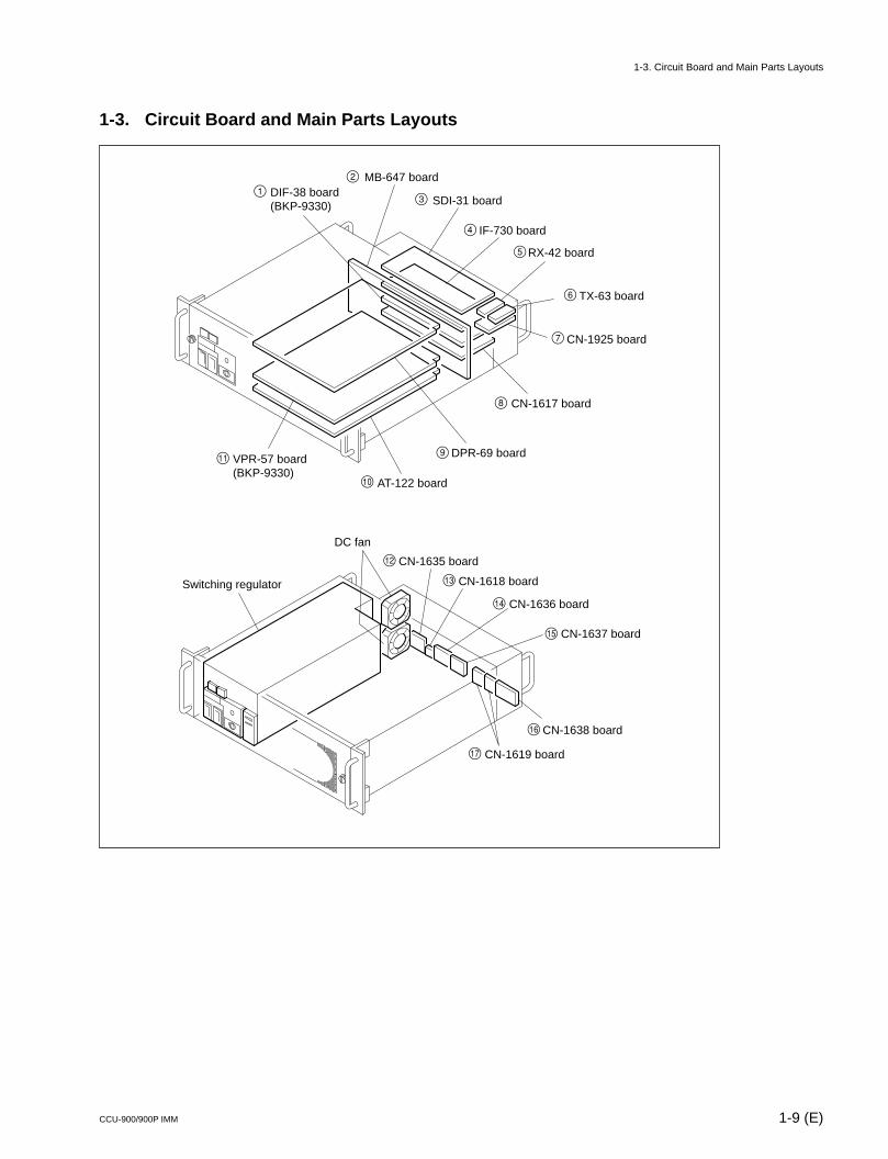
1-3. Circuit Board and Main Parts Layouts
TX-63 board
RX-42 board
CN-1925 board
CN-1617 board
DPR-69 board
AT-122 board
SDI-31 board
IF-730 board
MB-647 board
VPR-57 board(BKP-9330)
DIF-38 board(BKP-9330)
12
3
4
5
6
7
8
9
0
!-
Switching regulator
DC fan
CN-1618 board
CN-1619 board
CN-1635 board
CN-1636 board
CN-1637 board
CN-1638 board
!=
![
!]
!\
!;
!'
1-3. Circuit Board and Main Parts Layouts
1-10 (E) CCU-900/900P IMM
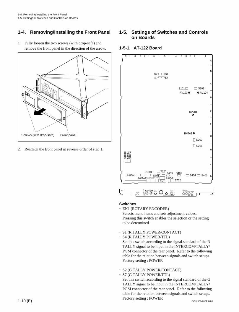
1-4. Removing/Installing the Front Panel
1. Fully loosen the two screws (with drop-safe) andremove the front panel in the direction of the arrow.
2. Reattach the front panel in reverse order of step 1.
1-5. Settings of Switches and Controlson Boards
1-5-1. AT-122 Board
Switches. EN1 (ROTARY ENCODER)
Selects menu items and sets adjustment values.Pressing this switch enables the selection or the settingto be determined.
. S1 (R TALLY POWER/CONTACT)
. S4 (R TALLY POWER/TTL)Set this switch according to the signal standard of the RTALLY signal to be input in the INTERCOM/TALLY/PGM connector of the rear panel. Refer to the followingtable for the relation between signals and switch setups.Factory setting : POWER
. S2 (G TALLY POWER/CONTACT)
. S7 (G TALLY POWER/TTL)Set this switch according to the signal standard of the GTALLY signal to be input in the INTERCOM/TALLY/PGM connector of the rear panel. Refer to the followingtable for the relation between signals and switch setups.Factory setting : POWER
Screws (with drop-safe) Front panel
1
11
1
S1003S1002
S1001
S10
10S
1011
S10
04
EN1
S701
S703S403 S401
S702S1006
S404 S402
S201
S202
RV703
RV704
RV104RV103
S1S4
S2S7
S101 S102
MIN
CH-1 CH-2
ON
ENTER CANCELENG PRODPRIVATE
OFFMIN
NORM NORMMIC LEVEL
POWER
MENU INCOMSELECT
PGMMIX
SIDETONE RTS
ENG PROD
CANCEL
123456789
A
B
C
D
E
F
G
H
J
K
1-4. Removing/Installing the Front Panel1-5. Settings of Switches and Controls on Boards
1-11 (E)CCU-900/900P IMM
. S701 (INPUT SELECT)Set this switch to 1ch (PROD), 2ch (PROD, ENG)according to the intercom system. When 1ch is set,PROD is fixed regardless of the setting of the ENG/PROD select switches of the camera and the CCU.Factory setting : 2ch
. S702 (INCOM SELECT)Select the line to which the intercom of the front panel isconnected.
PROD : Producer linePRIVATE : Private lineENG : Engineer line
Factory setting : PROD
. S703 (INCOM MIX)Select the line to which the intercom of the front panel isconnected.
ON : Connected to both of the producer line and theengineer line.
OFF : Depends on the setting of S702.Factory setting : OFF
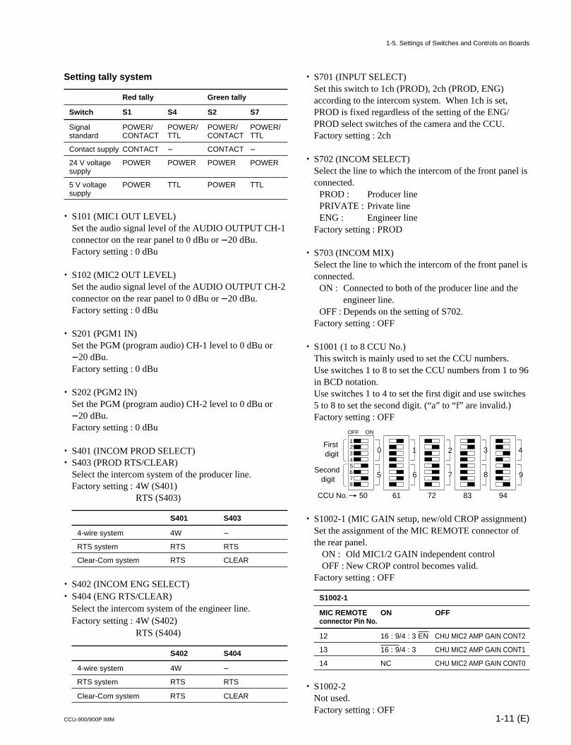
. S1001 (1 to 8 CCU No.)This switch is mainly used to set the CCU numbers.Use switches 1 to 8 to set the CCU numbers from 1 to 96in BCD notation.Use switches 1 to 4 to set the first digit and use switches5 to 8 to set the second digit. (“a” to “f” are invalid.)Factory setting : OFF
. S1002-1 (MIC GAIN setup, new/old CROP assignment)Set the assignment of the MIC REMOTE connector ofthe rear panel.
ON : Old MIC1/2 GAIN independent controlOFF : New CROP control becomes valid.
Factory setting : OFF
S1002-1
MIC REMOTE ON OFFconnector Pin No.
12 16 : 9/4 : 3 EN CHU MIC2 AMP GAIN CONT2
13 16 : 9/4 : 3 CHU MIC2 AMP GAIN CONT1
14 NC CHU MIC2 AMP GAIN CONT0
. S1002-2Not used.Factory setting : OFF
Setting tally system
Red tally Green tally
Switch S1 S4 S2 S7
Signal POWER/ POWER/ POWER/ POWER/standard CONTACT TTL CONTACT TTL
Contact supply CONTACT _ CONTACT _
24 V voltage POWER POWER POWER POWERsupply
5 V voltage POWER TTL POWER TTLsupply
. S101 (MIC1 OUT LEVEL)Set the audio signal level of the AUDIO OUTPUT CH-1connector on the rear panel to 0 dBu or _20 dBu.Factory setting : 0 dBu
. S102 (MIC2 OUT LEVEL)Set the audio signal level of the AUDIO OUTPUT CH-2connector on the rear panel to 0 dBu or _20 dBu.Factory setting : 0 dBu
. S201 (PGM1 IN)Set the PGM (program audio) CH-1 level to 0 dBu or_20 dBu.Factory setting : 0 dBu
. S202 (PGM2 IN)Set the PGM (program audio) CH-2 level to 0 dBu or_20 dBu.Factory setting : 0 dBu
. S401 (INCOM PROD SELECT)
. S403 (PROD RTS/CLEAR)Select the intercom system of the producer line.Factory setting : 4W (S401)
RTS (S403)
S401 S403
4-wire system 4W _
RTS system RTS RTS
Clear-Com system RTS CLEAR
. S402 (INCOM ENG SELECT)
. S404 (ENG RTS/CLEAR)Select the intercom system of the engineer line.Factory setting : 4W (S402)
RTS (S404)
S402 S404
4-wire system 4W _
RTS system RTS RTS
Clear-Com system RTS CLEAR
OFF ON
12345678
First digit
Second digit
CCU No.
0 1 2 3 4
5 6 7 8 9
50 61 72 83 94
1-5. Settings of Switches and Controls on Boards
1-12 (E) CCU-900/900P IMM
. S1002-3 (CB CAMERA POWER independent/interlock)Set whether color bars or gray pattern is output beforethe camera signal is output when the power of the CCUis turned on.
ON : Interlock (Outputs color bar or gray patternaccording to the setting of S1003-3.)
OFF : Independent (Not output.)Factory setting : OFF
. S1002-4 (MONI SEL system 1, 2 independent/interlock)Select a control system of the PIX1/2 and WF1/2connector output.
ON : Interlock (Controls PIX1 and PIX2, and WF1and WF2 simultaneously from MSU or RCP.)
OFF : Independent (Controls PIX1 and WF1 fromRCP and PIX2 and WF2 from MSU.)
Factory setting : OFF
. S1002-5 (board diagnosis display ON/OFF)When the CHARACTER button on the control panel ofRCP goes off, set whether the error message is displayedduring Auto Setup and Diagnosis (self-diagnosis).
ON : Does not display the error message.OFF : Normal mode (Displays the error message.)
Factory setting : OFF
. S1002-6Not used.Factory setting : OFF
. S1002-7 (CB CHARACTER OFF/ON)Set ON or OFF of the character signal that is super-imposed on the color-bars signal output from CCU.
ON : Character superimposedOFF : Character not superimposed
Factory setting: OFF
. S1002-8 (BACKUP data initialization)Use this switch to return all the set values to the factorysettings. Set the switch to ON and turn on the power ofthe CCU to return to the factory settings.nBe sure to set the switch to OFF after initialization.
Factory setting : OFF
. S1003-1Not used.Factory setting : OFF
. S1003-2 (No Light Gray)When the incident light level is lower than the specifiedlevel, gray pattern is output from the CCU.
ON : Function OFF (Gray pattern is not output)OFF : Function ON (Gray pattern is output)
Factory setting : OFF
. S1003-3 (CB/GRAY during CB interlock)Select the pattern that is output when S1002-2 is inter-locked.
ON : Gray patternOFF : Color bars
Factory setting: OFF
. S1003-4Not used.Factory setting : OFF
. S1003-5 (external TALLY/S-bus)Select whether the INTERCOM/TALLY/PGM connec-tor of the rear panel is used for TALLY control orwhether S-bus/CNU is used for TALLY control.
ON : S-busOFF : INTERCOM/TALLY/PGM connector
Factory setting : OFF
. S1003-6 (WFM PRESET reflection address)When S1002-3 is set to OFF, select whether the RE-CALL signal input from the WF MODE connector (D-sub 15-pin) is interlocked with RCP or MSU.
ON : MSUOFF : RCP
Factory setting : All OFF
. S1003-7 to 8Not used.Factory setting : All OFF
. S1004 (MENU ON/OFF)Use this switch to display the setup menu.
ON : Displays.OFF : Does not display.
. S1006 (MENU ENTER/CANCEL)When S1004 is set to ON, use this switch to select itemsfrom the setup menu, cancel the setting or return to thedefault setting.
1-5. Settings of Switches and Controls on Boards
1-13 (E)CCU-900/900P IMM
. S1010 (MIC CH-1 LEVEL)
. S1011 (MIC CH-2 LEVEL)Use these switches to switch AMP GAIN of MIC CH-1/CH-2 of the camera head using this unit. Set GAIN to60 dBu (NORMAL), 50 dBu, 40 dBu, 30 dBu or 20 dBu(MIN) according to MIC sensitivity and audio conditionsduring shooting.Factory setting : “NORM” (60 dBu)(0 dBu = 0.775 Vrms)
Controls. RV103 (MIC1 OUT LEVEL)
Set the output level of MIC OUTPUT 1.
. RV104 (MIC2 OUT LEVEL)Set the output level of MIC OUTPUT 2.
. RV703 (TALK LEVEL)Set the TALK level of the headset.
. RV704 (RECEIVE LEVEL)Set the RECEIVE level of the headset.
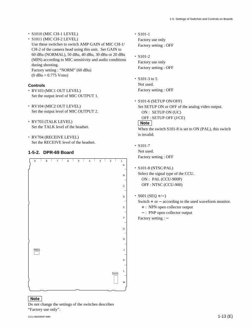
1-5-2. DPR-69 Board
nDo not change the settings of the switches describes“Factory use only”.
A
B
C
D
E
F
G
H
J
K
L
M
123456789
S101
S601
. S101-1Factory use onlyFactory setting : OFF
. S101-2Factory use onlyFactory setting : OFF
. S101-3 to 5Not used.Factory setting : OFF
. S101-6 (SETUP ON/OFF)Set SETUP ON or OFF of the analog video output.
ON : SETUP ON (UC)OFF : SETUP OFF (J/CE)
nWhen the switch S101-8 is set to ON (PAL), this switchis invalid.
. S101-7Not used.Factory setting : OFF
. S101-8 (NTSC/PAL)Select the signal type of the CCU.
ON : PAL (CCU-900P)OFF : NTSC (CCU-900)
. S601 (SEQ +/_)Switch + or _ according to the used waveform monitor.+ : NPN open collector output_ : PNP open collector output
Factory setting : _
1-5. Settings of Switches and Controls on Boards
1-14 (E) CCU-900/900P IMM
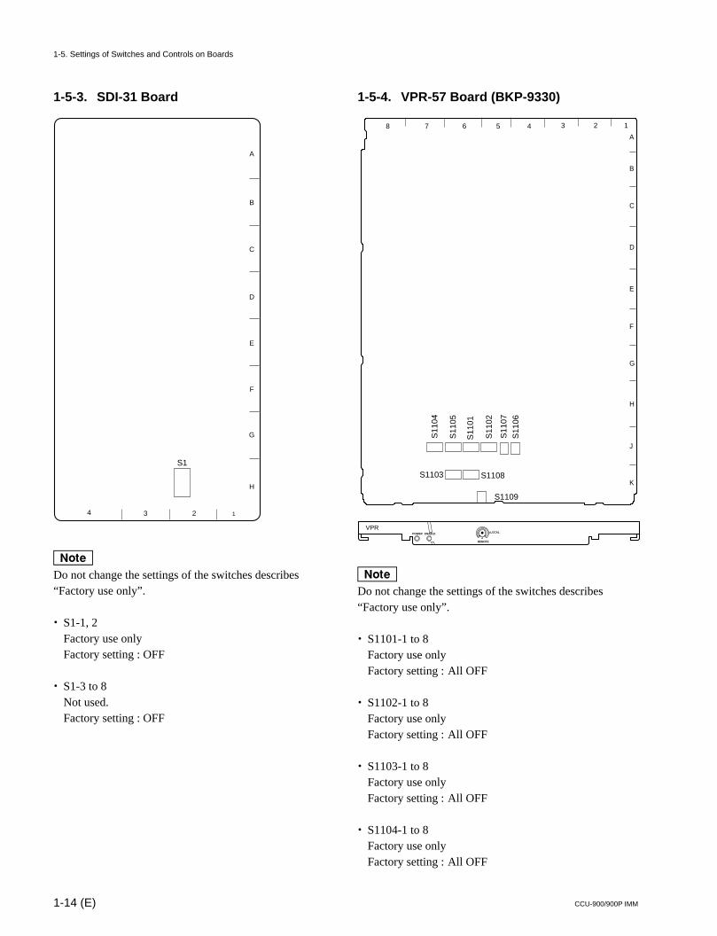
1-5-3. SDI-31 Board
nDo not change the settings of the switches describes“Factory use only”.
. S1-1, 2Factory use onlyFactory setting : OFF
. S1-3 to 8Not used.Factory setting : OFF
A
B
C
D
E
F
G
H
1234
S1
1-5. Settings of Switches and Controls on Boards
1-5-4. VPR-57 Board (BKP-9330)
POWER ENABLE
VPR
REMOTE
LOCAL
A
B
C
D
E
F
G
H
J
K
S11
01
S11
02
S1103
S11
04
S11
05
S11
06
S11
07
S1108
S1109
12345678
nDo not change the settings of the switches describes“Factory use only”.
. S1101-1 to 8Factory use onlyFactory setting : All OFF
. S1102-1 to 8Factory use onlyFactory setting : All OFF
. S1103-1 to 8Factory use onlyFactory setting : All OFF
. S1104-1 to 8Factory use onlyFactory setting : All OFF
1-15 (E)CCU-900/900P IMM
. S1105-1 to 8Factory use onlyFactory setting : All OFF
. S1106Factory use onlyFactory setting : 0
. S1107Factory use onlyFactory setting : 0
. S1108 (three-time speed output format)Select the format of the super motion video the SS-A,SS-B and SS-C connectors on the rear panel) outputfrom the DIF-38 board so that the output video signalformat agrees with that of the input format of therecording equipment connected to the CCU-900/900P.
MAV: Format conforming to multi-access videodisk recorder MAV-555 (when the optionalsuper motion input board BKMA-520SS isinstalled).
DISC2 : Format conforming to EAV SLMSDISC3 : Not used.
Factory setting : MAV
01
23
45 6
78
9
1-5. Settings of Switches and Controls on Boards
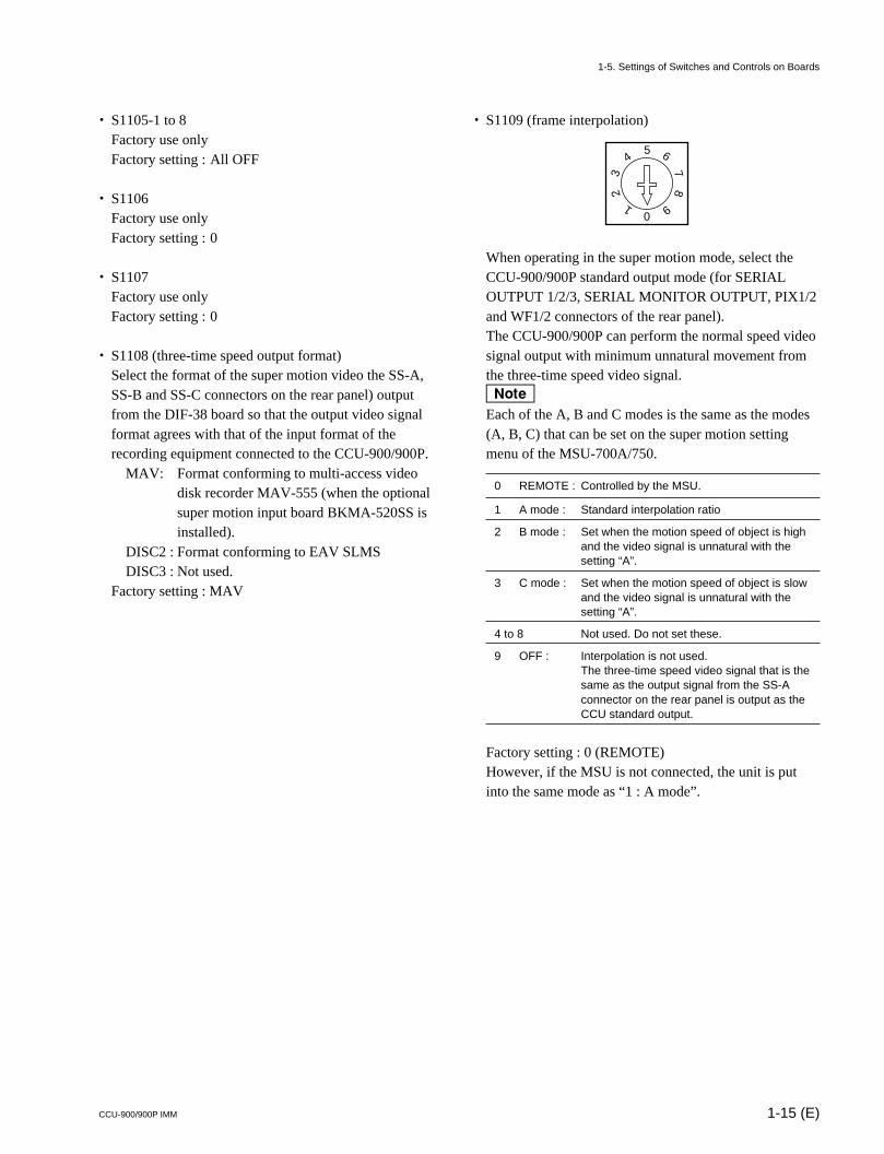
. S1109 (frame interpolation)
When operating in the super motion mode, select theCCU-900/900P standard output mode (for SERIALOUTPUT 1/2/3, SERIAL MONITOR OUTPUT, PIX1/2and WF1/2 connectors of the rear panel).The CCU-900/900P can perform the normal speed videosignal output with minimum unnatural movement fromthe three-time speed video signal.nEach of the A, B and C modes is the same as the modes(A, B, C) that can be set on the super motion settingmenu of the MSU-700A/750.
0 REMOTE : Controlled by the MSU.
1 A mode : Standard interpolation ratio
2 B mode : Set when the motion speed of object is highand the video signal is unnatural with thesetting “A”.
3 C mode : Set when the motion speed of object is slowand the video signal is unnatural with thesetting “A”.
4 to 8 Not used. Do not set these.
9 OFF : Interpolation is not used.The three-time speed video signal that is thesame as the output signal from the SS-Aconnector on the rear panel is output as theCCU standard output.
Factory setting : 0 (REMOTE)However, if the MSU is not connected, the unit is putinto the same mode as “1 : A mode”.
1-16 (E) CCU-900/900P IMM
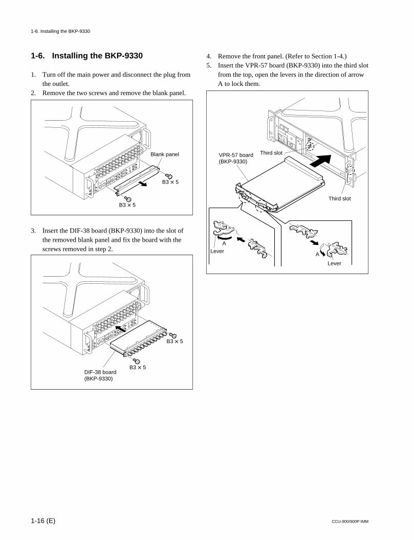
1-6. Installing the BKP-9330
1. Turn off the main power and disconnect the plug fromthe outlet.
2. Remove the two screws and remove the blank panel.
3. Insert the DIF-38 board (BKP-9330) into the slot ofthe removed blank panel and fix the board with thescrews removed in step 2.
4. Remove the front panel. (Refer to Section 1-4.)5. Insert the VPR-57 board (BKP-9330) into the third slot
from the top, open the levers in the direction of arrowA to lock them.
Blank panel
B3 x 5
B3 x 5
B3 x 5
B3 x 5DIF-38 board (BKP-9330)
Lever
Third slot
Third slot
LeverA
A
VPR-57 board (BKP-9330)
1-6. Installing the BKP-9330
1-17 (E)CCU-900/900P IMM
Manufacturer :UNITED STATES..... Accuride
12311 Shoemaker AvenueSanta Fe Springs, CA 90670TEL 213-903-0200FAX 213-903-0208
..... AccurideQuality DriveCharlotte, NC 28217TEL 704-588-5880FAX 704-588-6316
..... Accuride1930 Parco AvenueOntario, CA 91761TEL 714-923-9922FAX 714-947-8586
WEST GERMANY..... Standard-Praezision GmbH
Postfach 1464Werner-von-Siemens-Strasse 16-186252 Diez/Lahn West GermanyTEL 6432-6080FAX 6432-60820
UNITED KINGDOM..... Accuride Limited
Lilliput RoadBrackmills Industrial EstateNorthampton, NN4 OARUnited KingdomTEL 604-761111FAX 604-767190
1-7. Installing in 19-inch Rack
The unit can be mounted in a 19-inch EIA standard rack(height three unit).
w. To prevent turning over the rack, fix the rack on the
horizontal and firm floor securely using the bolts.. Do not install at a height of 1 m or higher from the floor.
If the rack falls, death or serious injury may result.When attaching the unit, be sure to fix the rack on thefloor and be careful not to attach at a height of 1 m orhigher from the floor.
Required Parts
cUse the specified rack mount rail.If not, injury could occur by drop of the unit becausestrength of rail is not enough.
. Slide rail : 1 setAccuride No.305A-18 (457 mm)
. Front brackets : 2 pcsSony P/N 2-142-214-01
. Rear brackets : 2 pcsSony P/N 2-142-215-01
. Screws (B4 x 8) : 14 pcs
. Screws (B5 x 8) : 8 pcs
. Plate nut : 1 pcSony P/N 3-651-812-00
. Screws for rack mounting (RK5 x 14) : 4 pcs
. Washers for rack mounting : 4 pcsSony P/N 2-297-913-01
1-7. Installing in 19-inch Rack
1-18 (E) CCU-900/900P IMM
Stopper
Inner rail
Outer rail
B4 x 8
B4 x 8
Inner rail
Inner rail
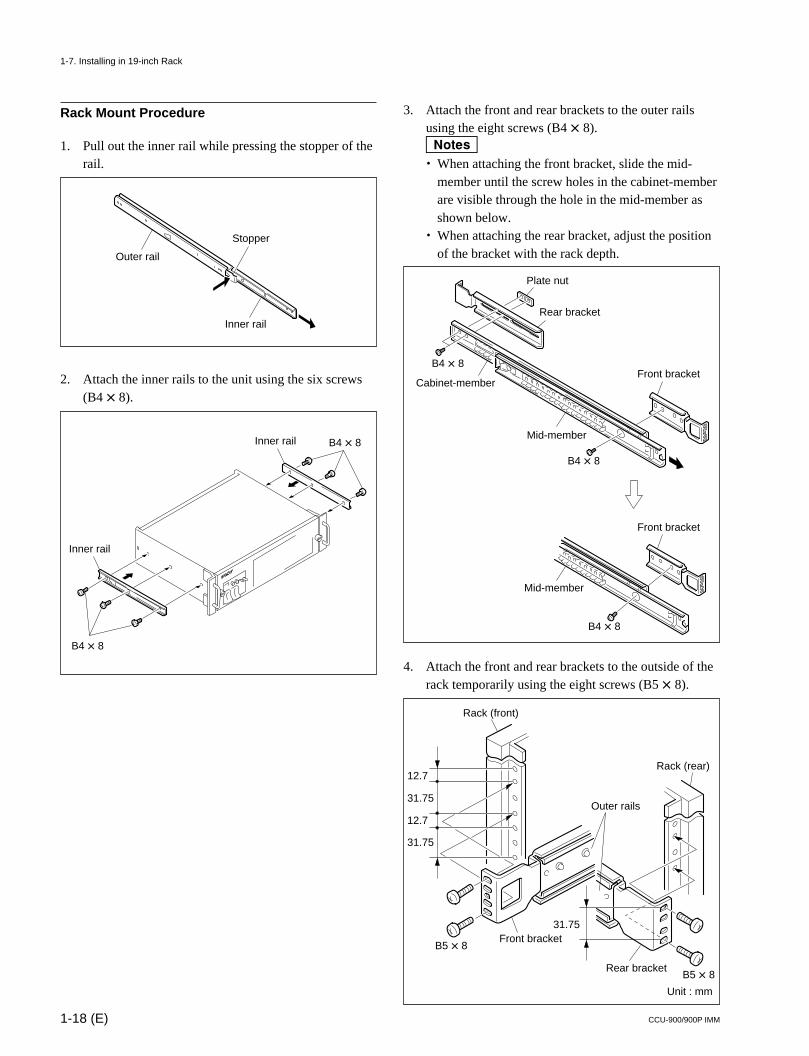
Rack Mount Procedure
1. Pull out the inner rail while pressing the stopper of therail.
2. Attach the inner rails to the unit using the six screws(B4 x 8).
3. Attach the front and rear brackets to the outer railsusing the eight screws (B4 x 8).m. When attaching the front bracket, slide the mid-
member until the screw holes in the cabinet-memberare visible through the hole in the mid-member asshown below.
. When attaching the rear bracket, adjust the positionof the bracket with the rack depth.
4. Attach the front and rear brackets to the outside of therack temporarily using the eight screws (B5 x 8).
12.7
31.75
12.7
31.75
31.75
Rack (front)
Rack (rear)
B5 x 8
B5 x 8
Front bracket
Rear bracket
Outer rails
Unit : mm
1-7. Installing in 19-inch Rack
B4 x 8
B4 x 8
Plate nut
Rear bracket
Front bracketCabinet-member
Mid-member
B4 x 8
Front bracket
Mid-member
1-19 (E)CCU-900/900P IMM
c. Mount the unit with more than two persons.
A one-man job may cause injury.. If you forget to fasten the screws of the rack angle, the
unit may slip and fall, causing injury.After rack mounting, be sure to fasten the screws.
. Install in a posture of stability.Injury could occur by drop of the unit in unbalancecondition of installation or removal. Install in a postureof stability and carefully.
. Be careful not to catch your finger or hand in rack mount rail.
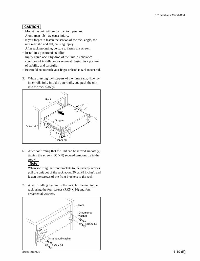
5. While pressing the stoppers of the inner rails, slide theinner rails fully into the outer rails, and push the unitinto the rack slowly.
6. After confirming that the unit can be moved smoothly,tighten the screws (B5 x 8) secured temporarily in thestep 4.nWhen securing the front brackets to the rack by screws,pull the unit out of the rack about 20 cm (8 inches), andfasten the screws of the front brackets to the rack.
7. After installing the unit in the rack, fix the unit to therack using the four screws (RK5 x 14) and fourornamental washers.
Rack
Outer rail
Inner rail
Stopper
Ornamental washer
RK5 x 14
Ornamental washer
RK5 x 14
Rack
1-7. Installing in 19-inch Rack

2-1 (E)CCU-900/900P IMM
Section 2Setting Menu
There is the setting menu consisting of the setup menu and the engineering menu. Various settings can beperformed in this setting menu.To use the setting menu, display it on the external monitor connected to the PIX1/2, SERIAL MONITORor CHARACTER connector on the rear panel of the unit.
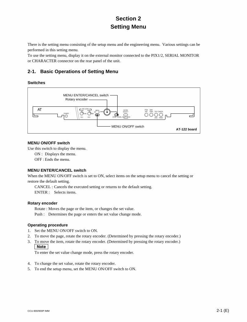
2-1. Basic Operations of Setting Menu
Switches
MENU ON/OFF switchUse this switch to display the menu.
ON : Displays the menu.OFF : Ends the menu.
MENU ENTER/CANCEL switchWhen the MENU ON/OFF switch is set to ON, select items on the setup menu to cancel the setting orrestore the default setting.
CANCEL : Cancels the executed setting or returns to the default setting.ENTER : Selects items.
Rotary encoderRotate : Moves the page or the item, or changes the set value.Push : Determines the page or enters the set value change mode.
Operating procedure1. Set the MENU ON/OFF switch to ON.2. To move the page, rotate the rotary encoder. (Determined by pressing the rotary encoder.)3. To move the item, rotate the rotary encoder. (Determined by pressing the rotary encoder.)
nTo enter the set value change mode, press the rotary encoder.
4. To change the set value, rotate the rotary encoder.5. To end the setup menu, set the MENU ON/OFF switch to ON.
MIN
CH-1 CH-2
ON
ENTER CANCEL ENG PRODPRIVATE
OFFMIN
NORM NORMMIC LEVEL
POWER
MENU INCOMSELECT
PGMMIX
SIDETONE RTS
ENG PROD
CANCEL
MENU ON/OFF switch
MENU ENTER/CANCEL switchRotary encoder
AT-122 board
2-2 (E) CCU-900/900P IMM
2-2. Setup Menu
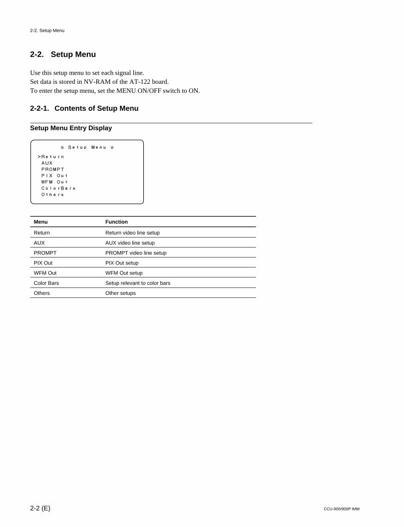
Use this setup menu to set each signal line.Set data is stored in NV-RAM of the AT-122 board.To enter the setup menu, set the MENU ON/OFF switch to ON.
2-2-1. Contents of Setup Menu
Setup Menu Entry Display
Menu Function
Return Return video line setup
AUX AUX video line setup
PROMPT PROMPT video line setup
PIX Out PIX Out setup
WFM Out WFM Out setup
Color Bars Setup relevant to color bars
Others Other setups
* Setup Menu *
>Return
AUX
PROMPT
PIX Out
WFM Out
ColorBars
Others
2-2. Setup Menu
2-3 (E)CCU-900/900P IMM
* Return *
>RET1 D-RET1 Active IN
RET2 D-RET2
RET3 A-RET1
RET4 A-RET2
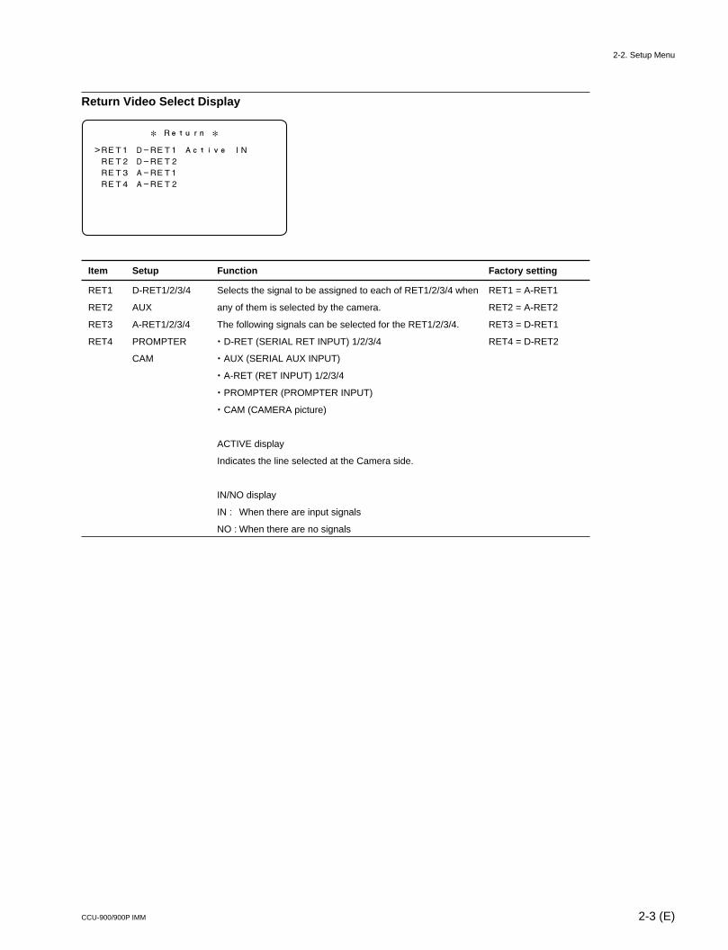
Return Video Select Display
Item Setup Function Factory setting
RET1 D-RET1/2/3/4 Selects the signal to be assigned to each of RET1/2/3/4 when RET1 = A-RET1
RET2 AUX any of them is selected by the camera. RET2 = A-RET2
RET3 A-RET1/2/3/4 The following signals can be selected for the RET1/2/3/4. RET3 = D-RET1
RET4 PROMPTER . D-RET (SERIAL RET INPUT) 1/2/3/4 RET4 = D-RET2
CAM . AUX (SERIAL AUX INPUT)
. A-RET (RET INPUT) 1/2/3/4
. PROMPTER (PROMPTER INPUT)
. CAM (CAMERA picture)
ACTIVE display
Indicates the line selected at the Camera side.
IN/NO display
IN : When there are input signals
NO : When there are no signals
2-2. Setup Menu
2-4 (E) CCU-900/900P IMM
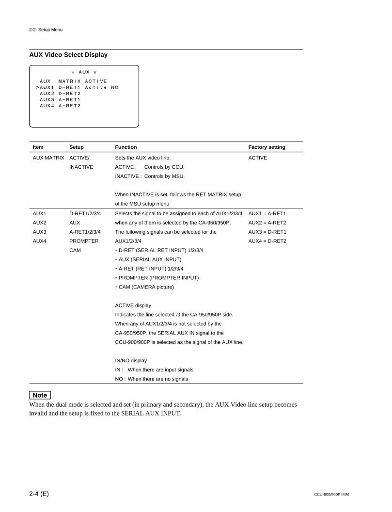
AUX Video Select Display
Item Setup Function Factory setting
AUX MATRIX ACTIVE/ Sets the AUX video line. ACTIVE
INACTIVE ACTIVE : Controls by CCU.
INACTIVE : Controls by MSU.
When INACTIVE is set, follows the RET MATRIX setup
of the MSU setup menu.
AUX1 D-RET1/2/3/4 Selects the signal to be assigned to each of AUX1/2/3/4 AUX1 = A-RET1
AUX2 AUX when any of them is selected by the CA-950/950P. AUX2 = A-RET2
AUX3 A-RET1/2/3/4 The following signals can be selected for the AUX3 = D-RET1
AUX4 PROMPTER AUX1/2/3/4 AUX4 = D-RET2
CAM . D-RET (SERIAL RET INPUT) 1/2/3/4
. AUX (SERIAL AUX INPUT)
. A-RET (RET INPUT) 1/2/3/4
. PROMPTER (PROMPTER INPUT)
. CAM (CAMERA picture)
ACTIVE display
Indicates the line selected at the CA-950/950P side.
When any of AUX1/2/3/4 is not selected by the
CA-950/950P, the SERIAL AUX IN signal to the
CCU-900/900P is selected as the signal of the AUX line.
IN/NO display
IN : When there are input signals
NO : When there are no signals
nWhen the dual mode is selected and set (in primary and secondary), the AUX Video line setup becomesinvalid and the setup is fixed to the SERIAL AUX INPUT.
* AUX *
AUX MATRIX ACTIVE
>AUX1 D-RET1 Active NO
AUX2 D-RET2
AUX3 A-RET1
AUX4 A-RET2
2-2. Setup Menu
2-5 (E)CCU-900/900P IMM
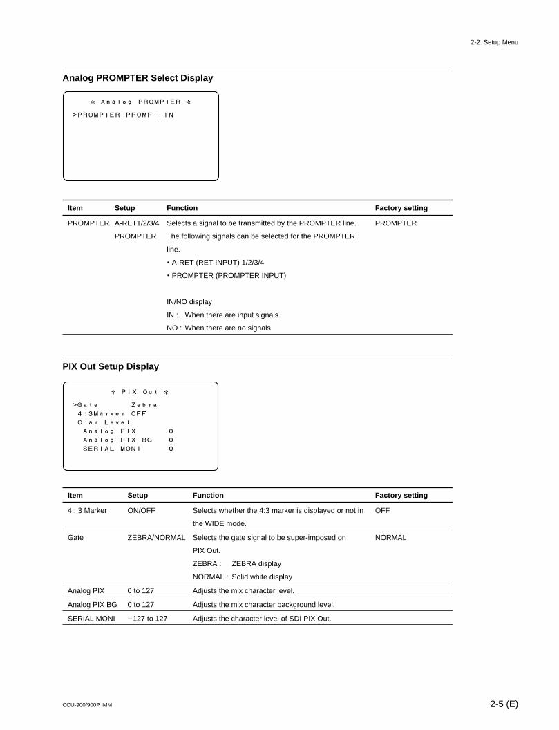
Analog PROMPTER Select Display
Item Setup Function Factory setting
PROMPTER A-RET1/2/3/4 Selects a signal to be transmitted by the PROMPTER line. PROMPTER
PROMPTER The following signals can be selected for the PROMPTER
line.
. A-RET (RET INPUT) 1/2/3/4
. PROMPTER (PROMPTER INPUT)
IN/NO display
IN : When there are input signals
NO : When there are no signals
PIX Out Setup Display
Item Setup Function Factory setting
4 : 3 Marker ON/OFF Selects whether the 4:3 marker is displayed or not in OFF
the WIDE mode.
Gate ZEBRA/NORMAL Selects the gate signal to be super-imposed on NORMAL
PIX Out.
ZEBRA : ZEBRA display
NORMAL : Solid white display
Analog PIX 0 to 127 Adjusts the mix character level.
Analog PIX BG 0 to 127 Adjusts the mix character background level.
SERIAL MONI _127 to 127 Adjusts the character level of SDI PIX Out.
* Analog PROMPTER *
>PROMPTER PROMPT IN
* PIX Out *
>Gate Zebra
4:3Marker OFF
Char Level
Analog PIX 0
Analog PIX BG 0
SERIAL MONI 0
2-2. Setup Menu
2-6 (E) CCU-900/900P IMM
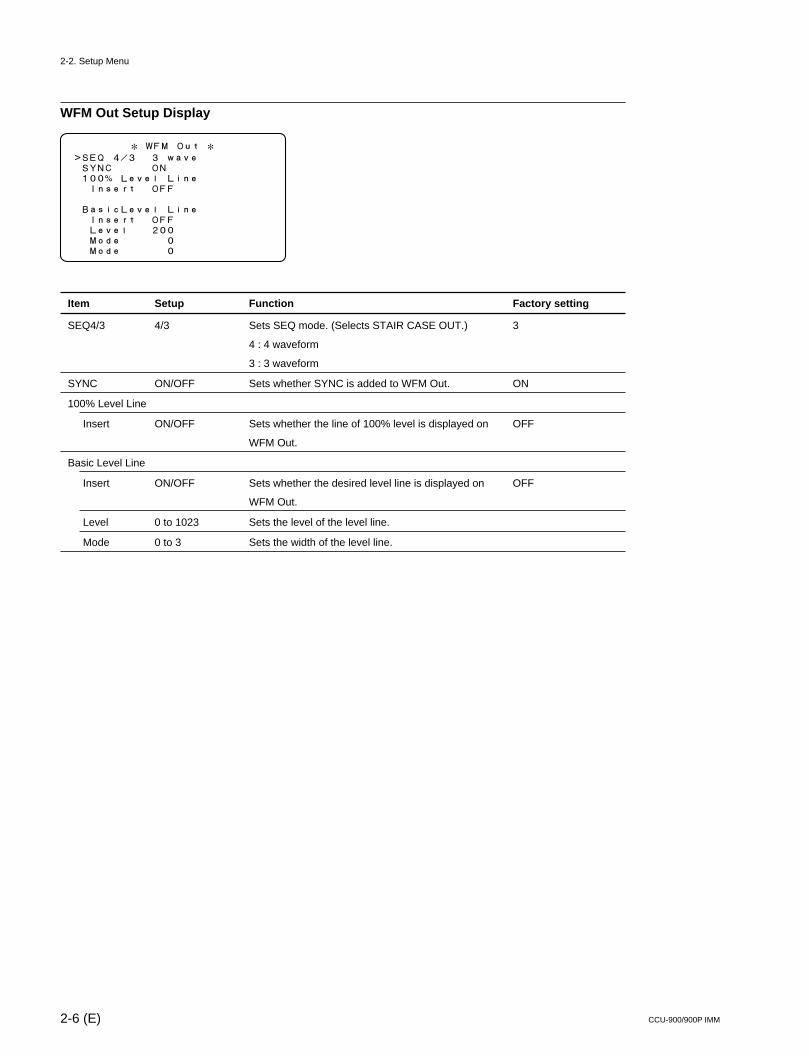
WFM Out Setup Display
Item Setup Function Factory setting
SEQ4/3 4/3 Sets SEQ mode. (Selects STAIR CASE OUT.) 3
4 : 4 waveform
3 : 3 waveform
SYNC ON/OFF Sets whether SYNC is added to WFM Out. ON
100% Level Line
Insert ON/OFF Sets whether the line of 100% level is displayed on OFF
WFM Out.
Basic Level Line
Insert ON/OFF Sets whether the desired level line is displayed on OFF
WFM Out.
Level 0 to 1023 Sets the level of the level line.
Mode 0 to 3 Sets the width of the level line.
* WFM Out *>SEQ 4/3 3 wave SYNC ON 100% Level Line Insert OFF
BasicLevel Line Insert OFF Level 200 Mode 0 Mode 0
2-2. Setup Menu
2-7 (E)CCU-900/900P IMM
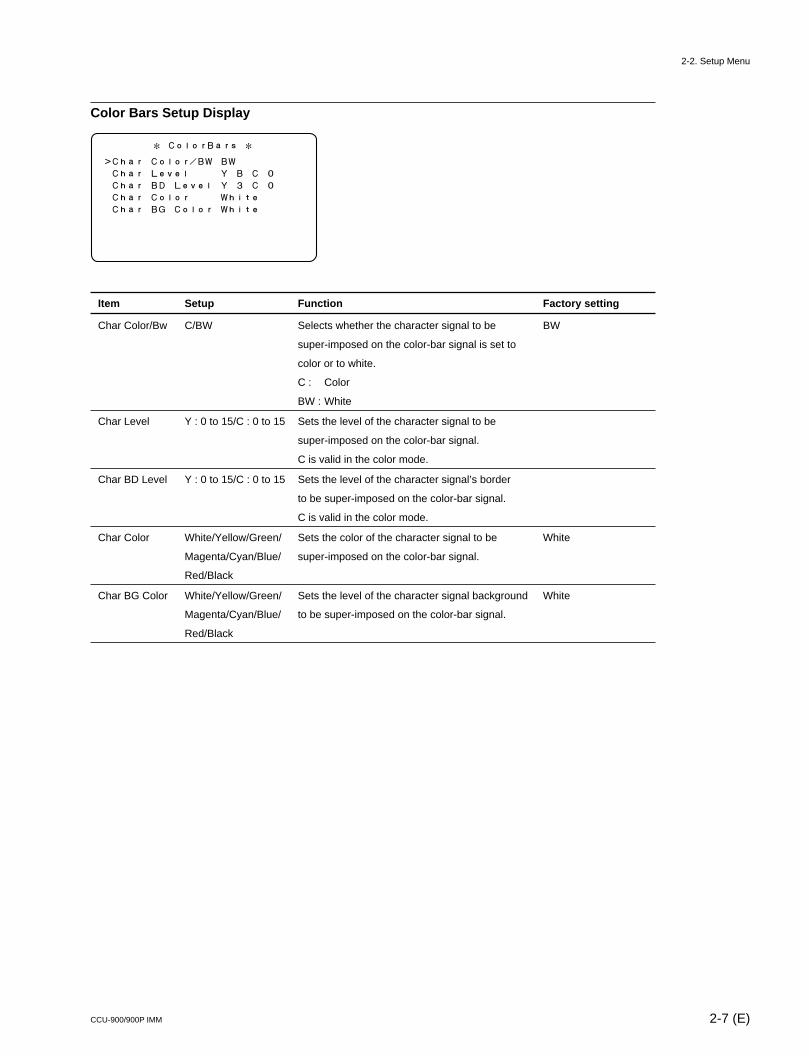
Color Bars Setup Display
Item Setup Function Factory setting
Char Color/Bw C/BW Selects whether the character signal to be BW
super-imposed on the color-bar signal is set to
color or to white.
C : Color
BW : White
Char Level Y : 0 to 15/C : 0 to 15 Sets the level of the character signal to be
super-imposed on the color-bar signal.
C is valid in the color mode.
Char BD Level Y : 0 to 15/C : 0 to 15 Sets the level of the character signal’s border
to be super-imposed on the color-bar signal.
C is valid in the color mode.
Char Color White/Yellow/Green/ Sets the color of the character signal to be White
Magenta/Cyan/Blue/ super-imposed on the color-bar signal.
Red/Black
Char BG Color White/Yellow/Green/ Sets the level of the character signal background White
Magenta/Cyan/Blue/ to be super-imposed on the color-bar signal.
Red/Black
* ColorBars *>Char Color/BW BW
Char Level Y B C 0
Char BD Level Y 3 C 0
Char Color White
Char BG Color White
2-2. Setup Menu
2-8 (E) CCU-900/900P IMM
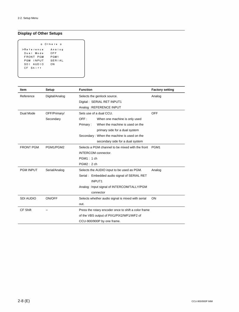
Display of Other Setups
Item Setup Function Factory setting
Reference Digital/Analog Selects the genlock source. Analog
Digital : SERIAL RET INPUT1
Analog : REFERENCE INPUT
Dual Mode OFF/Primary/ Sets use of a dual CCU. OFF
Secondary OFF : When one machine is only used
Primary : When the machine is used on the
primary side for a dual system
Secondary : When the machine is used on the
secondary side for a dual system
FRONT PGM PGM1/PGM2 Selects a PGM channel to be mixed with the front PGM1
INTERCOM connector.
PGM1 : 1 ch
PGM2 : 2 ch
PGM INPUT Serial/Analog Selects the AUDIO input to be used as PGM. Analog
Serial : Embedded audio signal of SERIAL RET
INPUT1
Analog : Input signal of INTERCOM/TALLY/PGM
connector
SDI AUDIO ON/OFF Selects whether audio signal is mixed with serial ON
out.
CF Shift _ Press the rotary encoder once to shift a color frame
of the VBS output of PIX1/PIX2/WF1/WF2 of
CCU-900/900P by one frame.
* Others *
>Reference Analog
Dual Mode OFF
FRONT PGM PGM1
PGM INPUT SERIAL
SDI AUDIO ON
CF Shift
2-2. Setup Menu
2-9 (E)CCU-900/900P IMM
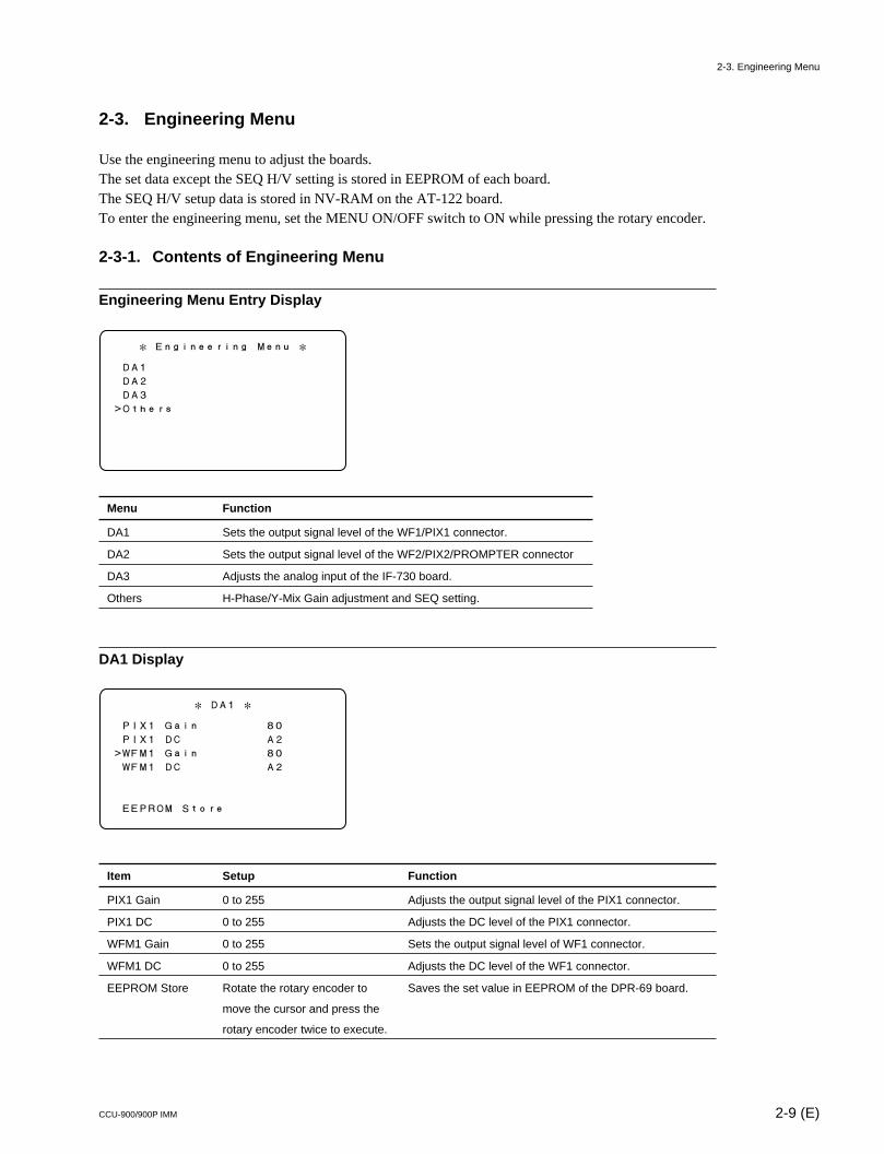
2-3. Engineering Menu
Use the engineering menu to adjust the boards.The set data except the SEQ H/V setting is stored in EEPROM of each board.The SEQ H/V setup data is stored in NV-RAM on the AT-122 board.To enter the engineering menu, set the MENU ON/OFF switch to ON while pressing the rotary encoder.
2-3-1. Contents of Engineering Menu
Engineering Menu Entry Display
Menu Function
DA1 Sets the output signal level of the WF1/PIX1 connector.
DA2 Sets the output signal level of the WF2/PIX2/PROMPTER connector
DA3 Adjusts the analog input of the IF-730 board.
Others H-Phase/Y-Mix Gain adjustment and SEQ setting.
DA1 Display
Item Setup Function
PIX1 Gain 0 to 255 Adjusts the output signal level of the PIX1 connector.
PIX1 DC 0 to 255 Adjusts the DC level of the PIX1 connector.
WFM1 Gain 0 to 255 Sets the output signal level of WF1 connector.
WFM1 DC 0 to 255 Adjusts the DC level of the WF1 connector.
EEPROM Store Rotate the rotary encoder to Saves the set value in EEPROM of the DPR-69 board.
move the cursor and press the
rotary encoder twice to execute.
* Engineering Menu *
DA1
DA2
DA3
>Others
* DA1 *
PIX1 Gain 80
PIX1 DC A2
>WFM1 Gain 80
WFM1 DC A2
EEPROM Store
2-3. Engineering Menu
2-10 (E) CCU-900/900P IMM
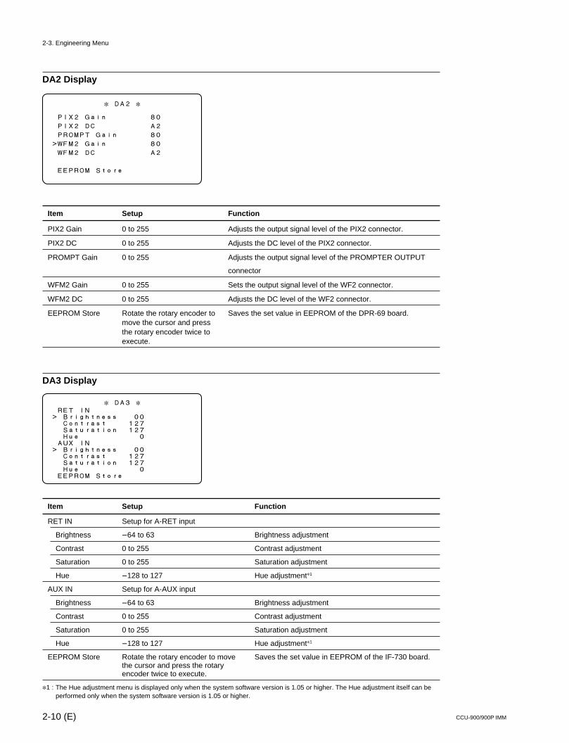
DA2 Display
Item Setup Function
PIX2 Gain 0 to 255 Adjusts the output signal level of the PIX2 connector.
PIX2 DC 0 to 255 Adjusts the DC level of the PIX2 connector.
PROMPT Gain 0 to 255 Adjusts the output signal level of the PROMPTER OUTPUT
connector
WFM2 Gain 0 to 255 Sets the output signal level of the WF2 connector.
WFM2 DC 0 to 255 Adjusts the DC level of the WF2 connector.
EEPROM Store Rotate the rotary encoder to Saves the set value in EEPROM of the DPR-69 board.move the cursor and pressthe rotary encoder twice toexecute.
DA3 Display
Item Setup Function
RET IN Setup for A-RET input
Brightness _64 to 63 Brightness adjustment
Contrast 0 to 255 Contrast adjustment
Saturation 0 to 255 Saturation adjustment
Hue _128 to 127 Hue adjustment*1
AUX IN Setup for A-AUX input
Brightness _64 to 63 Brightness adjustment
Contrast 0 to 255 Contrast adjustment
Saturation 0 to 255 Saturation adjustment
Hue _128 to 127 Hue adjustment*1
EEPROM Store Rotate the rotary encoder to move Saves the set value in EEPROM of the IF-730 board.the cursor and press the rotaryencoder twice to execute.
*1 : The Hue adjustment menu is displayed only when the system software version is 1.05 or higher. The Hue adjustment itself can beperformed only when the system software version is 1.05 or higher.
* DA2 *
PIX2 Gain 80
PIX2 DC A2
PROMPT Gain 80
>WFM2 Gain 80
WFM2 DC A2
EEPROM Store
* DA3 * RET IN> Brightness 00 Contrast 127 Saturation 127 Hue 0 AUX IN> Brightness 00 Contrast 127 Saturation 127 Hue 0 EEPROM Store
2-3. Engineering Menu
2-11 (E)CCU-900/900P IMM
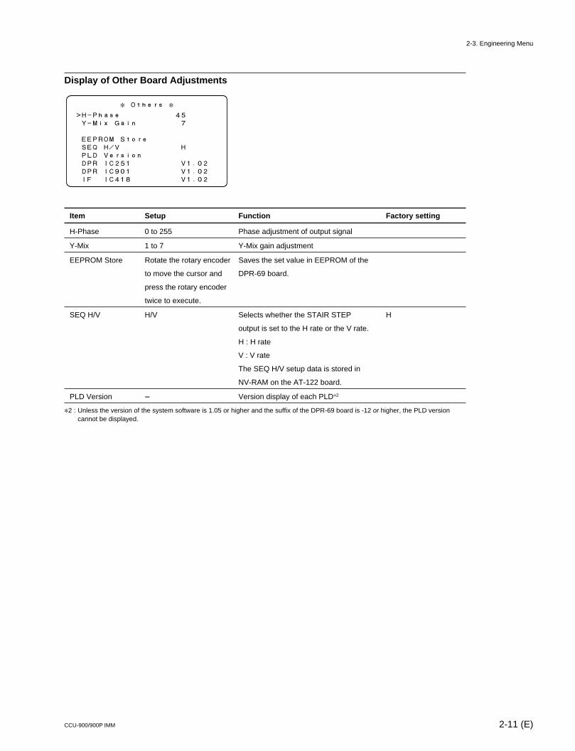
Display of Other Board Adjustments
Item Setup Function Factory setting
H-Phase 0 to 255 Phase adjustment of output signal
Y-Mix 1 to 7 Y-Mix gain adjustment
EEPROM Store Rotate the rotary encoder Saves the set value in EEPROM of the
to move the cursor and DPR-69 board.
press the rotary encoder
twice to execute.
SEQ H/V H/V Selects whether the STAIR STEP H
output is set to the H rate or the V rate.
H : H rate
V : V rate
The SEQ H/V setup data is stored in
NV-RAM on the AT-122 board.
PLD Version _ Version display of each PLD*2
*2 : Unless the version of the system software is 1.05 or higher and the suffix of the DPR-69 board is -12 or higher, the PLD versioncannot be displayed.
* Others *>H-Phase 45 Y-Mix Gain 7
EEPROM Store SEQ H/V H PLD Version DPR IC251 V1.02 DPR IC901 V1.02 IF IC418 V1.02
2-3. Engineering Menu

3-1 (E)CCU-900/900P IMM
Section 3System Setup
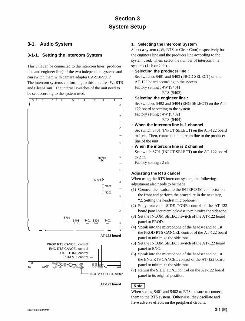
3-1. Audio System
3-1-1. Setting the Intercom System
This unit can be connected to the intercom lines (producerline and engineer line) of the two independent systems andcan switch them with camera adapter CA-950/950P.The intercom systems conforming to this unit are 4W, RTSand Clear-Com. The internal switches of the unit need tobe set according to the system used.
AT-122 board
AT-122 board
PGMMIX
SIDETONE RTS CANCEL
PRIVATE
MIN
CH-1 CH-2
ON
ENTER CANCELENG PROD
OFFMIN
NORM NORMMIC LEVEL
POWER
MENU INCOMSELECT
ENG PROD
INCOM SELECT switch
PROD RTS CANCEL controlENG RTS CANCEL control
SIDE TONE controlPGM MIX control
1. Selecting the Intercom SystemSelect a system (4W, RTS or Clear-Com) respectively forthe engineer line and the producer line according to thesystem used. Then, select the number of intercom linesystems (1 ch or 2 ch).. Selecting the producer line :
Set switches S401 and S403 (PROD SELECT) on theAT-122 board according to the system.Factory setting : 4W (S401)
RTS (S403). Selecting the engineer line :
Set switches S402 and S404 (ENG SELECT) on the AT-122 board according to the system.Factory setting : 4W (S402)
RTS (S404). When the intercom line is 1 channel :
Set switch S701 (INPUT SELECT) on the AT-122 boardto 1 ch. Then, connect the intercom line to the producerline of the unit.
. When the intercom line is 2 channel :Set switch S701 (INPUT SELECT) on the AT-122 boardto 2 ch.Factory setting : 2 ch
Adjusting the RTS cancelWhen using the RTS intercom system, the followingadjustment also needs to be made.(1) Connect the headset to the INTERCOM connector on
the front and perform the procedure in the next step,“2. Setting the headset microphone”.
(2) Fully rotate the SIDE TONE control of the AT-122board panel counterclockwise to minimize the side tone.
(3) Set the INCOM SELECT switch of the AT-122 boardpanel to PROD.
(4) Speak into the microphone of the headset and adjustthe PROD RTS CANCEL control of the AT-122 boardpanel to minimize the side tone.
(5) Set the INCOM SELECT switch of the AT-122 boardpanel to ENG.
(6) Speak into the microphone of the headset and adjustthe ENG RTS CANCEL control of the AT-122 boardpanel to minimize the side tone.
(7) Return the SIDE TONE control on the AT-122 boardpanel to its original position.
nWhen setting S401 and S402 to RTS, be sure to connectthem to the RTS system. Otherwise, they oscillate andhave adverse effects on the peripheral circuits.
11
S701S403 S401 S404 S402
S201
S202
RV703
RV704
123456789
A
B
C
D
E
F
G
H
J
K
3-2 (E) CCU-900/900P IMM
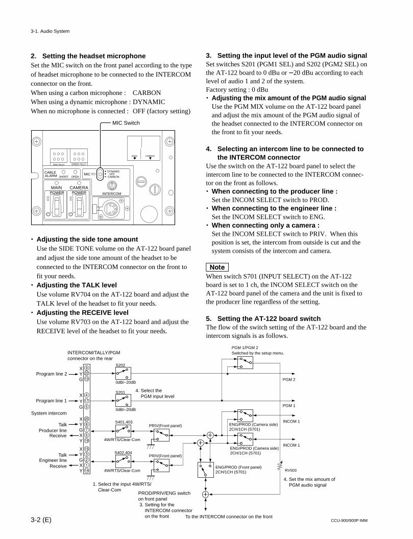
2. Setting the headset microphoneSet the MIC switch on the front panel according to the typeof headset microphone to be connected to the INTERCOMconnector on the front.When using a carbon microphone : CARBONWhen using a dynamic microphone : DYNAMICWhen no microphone is connected : OFF (factory setting)
. Adjusting the side tone amountUse the SIDE TONE volume on the AT-122 board paneland adjust the side tone amount of the headset to beconnected to the INTERCOM connector on the front tofit your needs.
. Adjusting the TALK levelUse volume RV704 on the AT-122 board and adjust theTALK level of the headset to fit your needs.
. Adjusting the RECEIVE levelUse volume RV703 on the AT-122 board and adjust theRECEIVE level of the headset to fit your needs.
DYNAMICOFF
CARBON
INTERCOM
CAMERA
MIC
POWERPOWERMAIN
CAMERAMAIN
RED TALLY GREEN TALLY
CABLEALARM SHORT OPEN
MIC Switch
3. Setting the input level of the PGM audio signalSet switches S201 (PGM1 SEL) and S202 (PGM2 SEL) onthe AT-122 board to 0 dBu or _20 dBu according to eachlevel of audio 1 and 2 of the system.Factory setting : 0 dBu. Adjusting the mix amount of the PGM audio signal
Use the PGM MIX volume on the AT-122 board paneland adjust the mix amount of the PGM audio signal ofthe headset connected to the INTERCOM connector onthe front to fit your needs.
4. Selecting an intercom line to be connected tothe INTERCOM connector
Use the switch on the AT-122 board panel to select theintercom line to be connected to the INTERCOM connec-tor on the front as follows.. When connecting to the producer line :
Set the INCOM SELECT switch to PROD.. When connecting to the engineer line :
Set the INCOM SELECT switch to ENG.. When connecting only a camera :
Set the INCOM SELECT switch to PRIV. When thisposition is set, the intercom from outside is cut and thesystem consists of the intercom and camera.
nWhen switch S701 (INPUT SELECT) on the AT-122board is set to 1 ch, the INCOM SELECT switch on theAT-122 board panel of the camera and the unit is fixed tothe producer line regardless of the setting.
5. Setting the AT-122 board switchThe flow of the switch setting of the AT-122 board and theintercom signals is as follows.
S201
S401,403
S402,404
0dB/–20dB
S202
0dB/–20dB
4W/RTS/Clear-Com
4W/RTS/Clear-Com
PRIV(Front panel)
PRIV(Front panel)
RV503ENG/PROD (Front panel)2CH/1CH (S701)
ENG/PROD (Camera side)2CH/1CH (S701)
ENG/PROD (Camera side)2CH/1CH (S701)
4X
5
@/875!.
!\321!]
YG
XYGXY
XYGXY
Program line 1
XYG
Program line 2
System intercom
TalkProducer line
Receive
Talk
Receive
INTERCOM/TALLY/PGM connector on the rear
4. Select the PGM input level
PGM 1
PGM 2
INCOM 1
INCOM 1
4. Set the mix amount of PGM audio signal
PROD/PRIV/ENG switch on front panel 3. Setting for the INTERCOM connector on the front
1. Select the input 4W/RTS/ Clear-Com
Engineer line
To the INTERCOM connector on the front
!'
9
!/@=
PGM 1/PGM 2Switched by the setup menu.
3-1. Audio System
3-3 (E)CCU-900/900P IMM
3-1-2. Setting the Microphone
This unit can output the two independent microphone lines(MIC 1, MIC 2) of video camera BVP-950/950P/9500WS/9500WSP and camera adapter CA-950/950P as it receivesthese MIC signals.
Controlling the Microphone Input Level from theRemote Control
This unit can adjust the input level of the MIC connector ofBVP-950/950P/9500WS/9500WSP and the input level ofthe MIC connector of CA-950/950P from the remotecontrol in 10 dBu steps in the range of _60 dBu to _20dBu using either of the following methods.
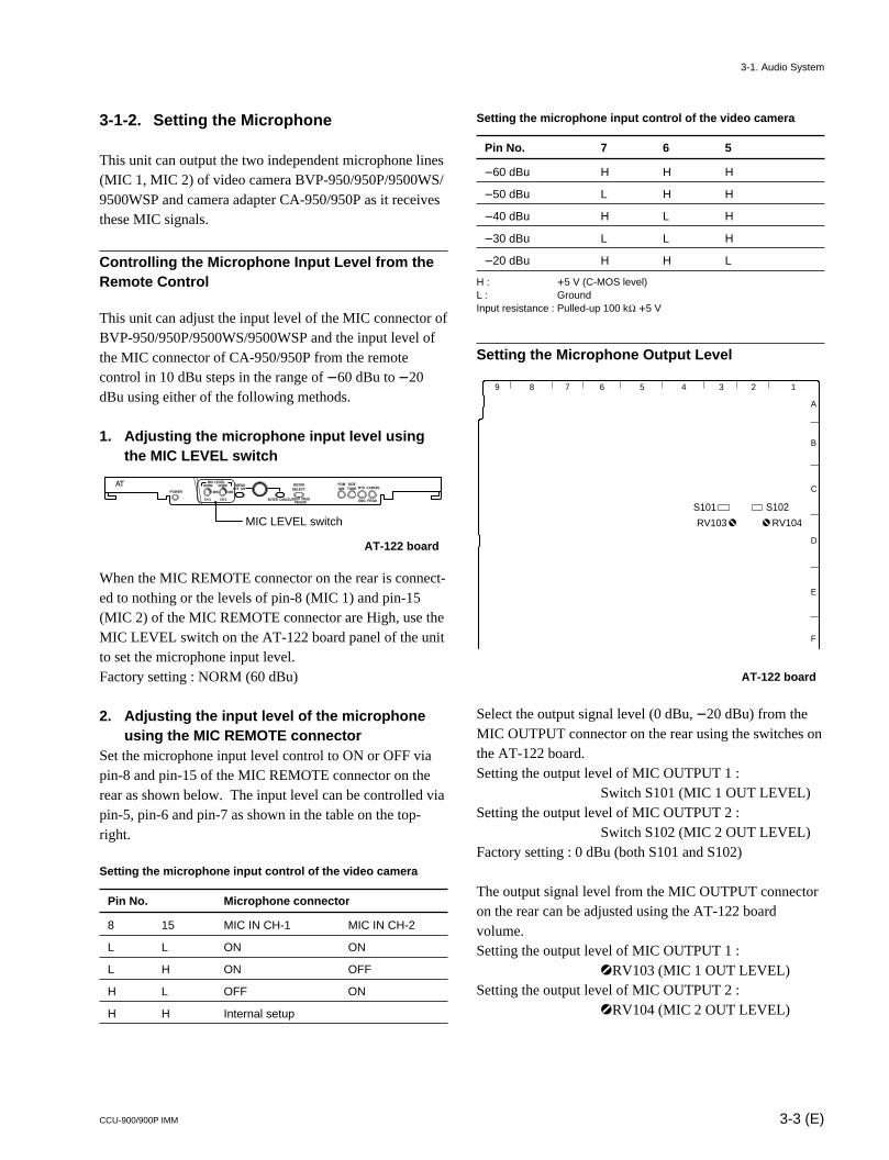
1. Adjusting the microphone input level usingthe MIC LEVEL switch
AT-122 board
When the MIC REMOTE connector on the rear is connect-ed to nothing or the levels of pin-8 (MIC 1) and pin-15(MIC 2) of the MIC REMOTE connector are High, use theMIC LEVEL switch on the AT-122 board panel of the unitto set the microphone input level.Factory setting : NORM (60 dBu)
2. Adjusting the input level of the microphoneusing the MIC REMOTE connector
Set the microphone input level control to ON or OFF viapin-8 and pin-15 of the MIC REMOTE connector on therear as shown below. The input level can be controlled viapin-5, pin-6 and pin-7 as shown in the table on the top-right.
Setting the microphone input control of the video camera
Pin No. Microphone connector
8 15 MIC IN CH-1 MIC IN CH-2
L L ON ON
L H ON OFF
H L OFF ON
H H Internal setup
Setting the microphone input control of the video camera
Pin No. 7 6 5
_60 dBu H H H
_50 dBu L H H
_40 dBu H L H
_30 dBu L L H
_20 dBu H H L
H : +5 V (C-MOS level)L : GroundInput resistance : Pulled-up 100 kZ +5 V
Setting the Microphone Output Level
AT-122 board
Select the output signal level (0 dBu, _20 dBu) from theMIC OUTPUT connector on the rear using the switches onthe AT-122 board.Setting the output level of MIC OUTPUT 1 :
Switch S101 (MIC 1 OUT LEVEL)Setting the output level of MIC OUTPUT 2 :
Switch S102 (MIC 2 OUT LEVEL)Factory setting : 0 dBu (both S101 and S102)
The output signal level from the MIC OUTPUT connectoron the rear can be adjusted using the AT-122 boardvolume.Setting the output level of MIC OUTPUT 1 :
1RV103 (MIC 1 OUT LEVEL)Setting the output level of MIC OUTPUT 2 :
1RV104 (MIC 2 OUT LEVEL)
PGMMIX
SIDETONE RTS CANCEL
PRIVATE
MIN
CH-1 CH-2
ON
ENTER CANCELENG PROD
OFFMIN
NORM NORMMIC LEVEL
POWER
MENU INCOMSELECT
ENG PROD
MIC LEVEL switch
3-1. Audio System
11
RV104RV103
S101 S102
123456789
A
B
C
D
E
F
3-4 (E) CCU-900/900P IMM
3-2. Systems
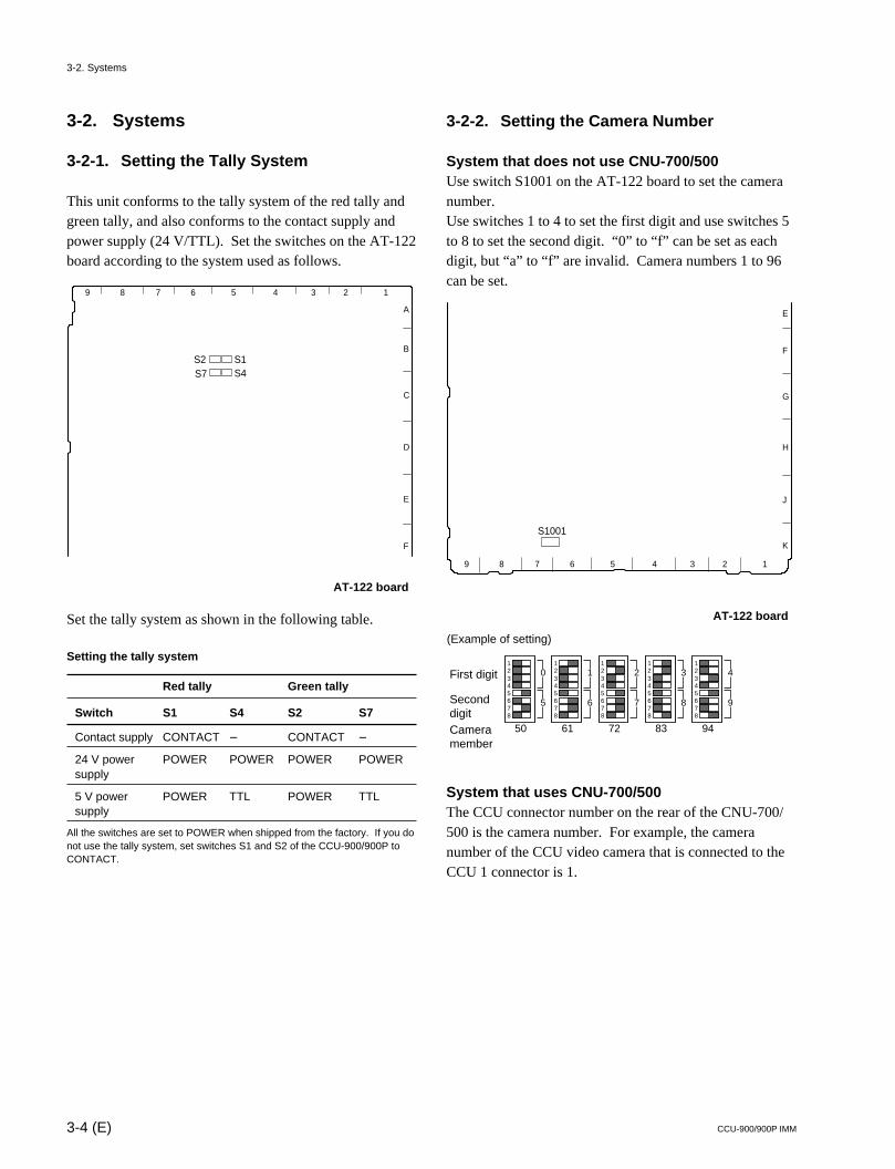
3-2-1. Setting the Tally System
This unit conforms to the tally system of the red tally andgreen tally, and also conforms to the contact supply andpower supply (24 V/TTL). Set the switches on the AT-122board according to the system used as follows.
AT-122 board
Set the tally system as shown in the following table.
Setting the tally system
Red tally Green tally
Switch S1 S4 S2 S7
Contact supply CONTACT _ CONTACT _
24 V power POWER POWER POWER POWERsupply
5 V power POWER TTL POWER TTLsupply
All the switches are set to POWER when shipped from the factory. If you donot use the tally system, set switches S1 and S2 of the CCU-900/900P toCONTACT.
3-2-2. Setting the Camera Number
System that does not use CNU-700/500Use switch S1001 on the AT-122 board to set the cameranumber.Use switches 1 to 4 to set the first digit and use switches 5to 8 to set the second digit. “0” to “f” can be set as eachdigit, but “a” to “f” are invalid. Camera numbers 1 to 96can be set.
AT-122 board
System that uses CNU-700/500The CCU connector number on the rear of the CNU-700/500 is the camera number. For example, the cameranumber of the CCU video camera that is connected to theCCU 1 connector is 1.
123456
0
78
50
5
123456
1
78
61
6
123456
2
78
72
7
123456
3
78
83
8
123456
4
78
94
9
(Example of setting)
First digit
Second digitCamera member
3-2. Systems
S1001
123456789
E
F
G
H
J
K
S1S4
S2S7
123456789
A
B
C
D
E
F
3-5 (E)CCU-900/900P IMM
3-3. Video Signal System
The equipment that is used for the BVP-900 series camerasystem and this unit were set to the specified level whenshipped from the factory. Before operating, check thesignal levels between each equipment and adjust them ifrequired. Some adjustments can be performed using themaintenance menu of the MSU-700A/750 instead of usingthe controls or switches on the board. Perform the basicadjustments on the board and perform the fine adjustmentson the maintenance menu.
3-3-1. Selecting the Input/Output Signal
Select the input/output terminal signal of the rear panelaccording to the video system to be installed.
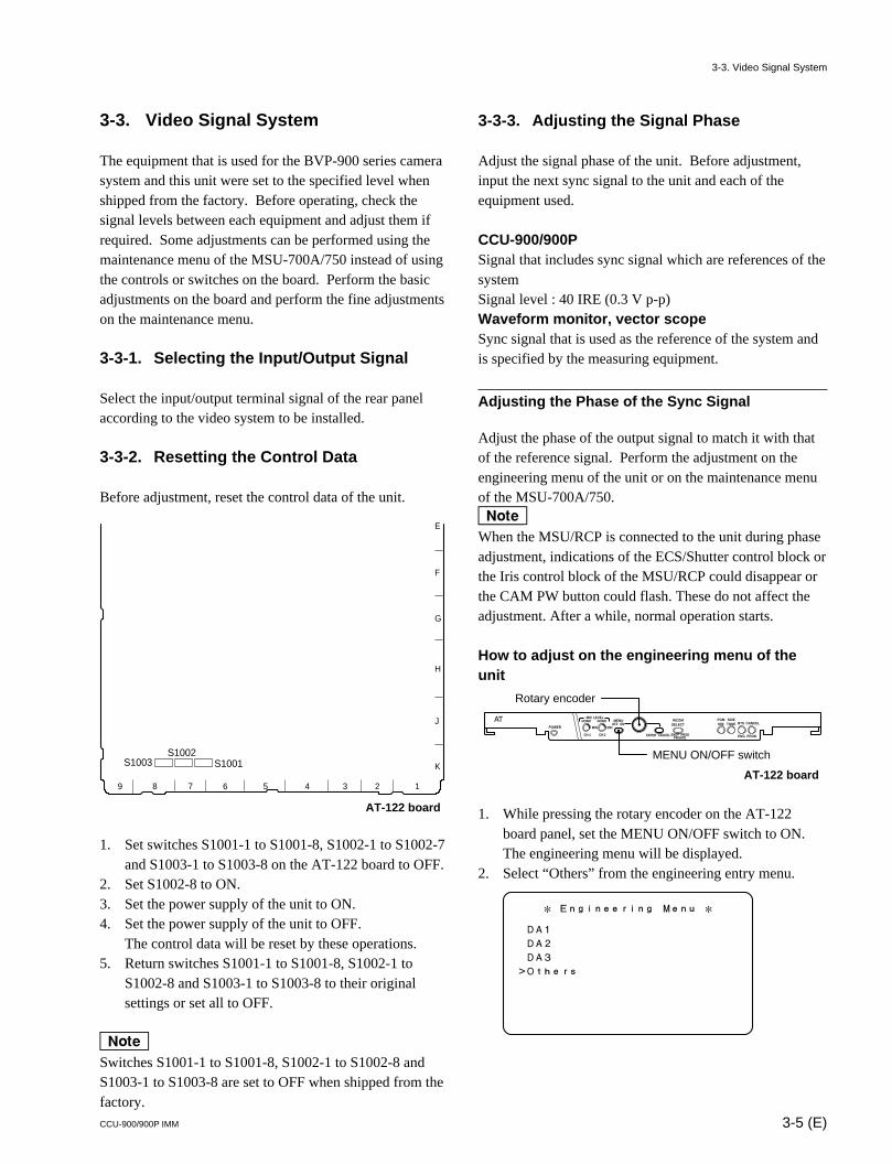
3-3-2. Resetting the Control Data
Before adjustment, reset the control data of the unit.
AT-122 board
1. Set switches S1001-1 to S1001-8, S1002-1 to S1002-7and S1003-1 to S1003-8 on the AT-122 board to OFF.
2. Set S1002-8 to ON.3. Set the power supply of the unit to ON.4. Set the power supply of the unit to OFF.
The control data will be reset by these operations.5. Return switches S1001-1 to S1001-8, S1002-1 to
S1002-8 and S1003-1 to S1003-8 to their originalsettings or set all to OFF.
nSwitches S1001-1 to S1001-8, S1002-1 to S1002-8 andS1003-1 to S1003-8 are set to OFF when shipped from thefactory.
3-3-3. Adjusting the Signal Phase
Adjust the signal phase of the unit. Before adjustment,input the next sync signal to the unit and each of theequipment used.
CCU-900/900PSignal that includes sync signal which are references of thesystemSignal level : 40 IRE (0.3 V p-p)Waveform monitor, vector scopeSync signal that is used as the reference of the system andis specified by the measuring equipment.
Adjusting the Phase of the Sync Signal
Adjust the phase of the output signal to match it with thatof the reference signal. Perform the adjustment on theengineering menu of the unit or on the maintenance menuof the MSU-700A/750.nWhen the MSU/RCP is connected to the unit during phaseadjustment, indications of the ECS/Shutter control block orthe Iris control block of the MSU/RCP could disappear orthe CAM PW button could flash. These do not affect theadjustment. After a while, normal operation starts.
How to adjust on the engineering menu of theunit
AT-122 board
1. While pressing the rotary encoder on the AT-122board panel, set the MENU ON/OFF switch to ON.The engineering menu will be displayed.
2. Select “Others” from the engineering entry menu.
MIN
CH-1 CH-2
ON
ENTER CANCEL ENG PRODPRIVATE
OFFMIN
NORM NORMMIC LEVEL
POWER
MENU INCOMSELECT
PGMMIX
SIDETONE RTS
ENG PROD
CANCEL
MENU ON/OFF switch
Rotary encoder
* Engineering Menu *
DA1
DA2
DA3
>Others
3-3. Video Signal System
S1003S1002
S1001
123456789
E
F
G
H
J
K
3-6 (E) CCU-900/900P IMM
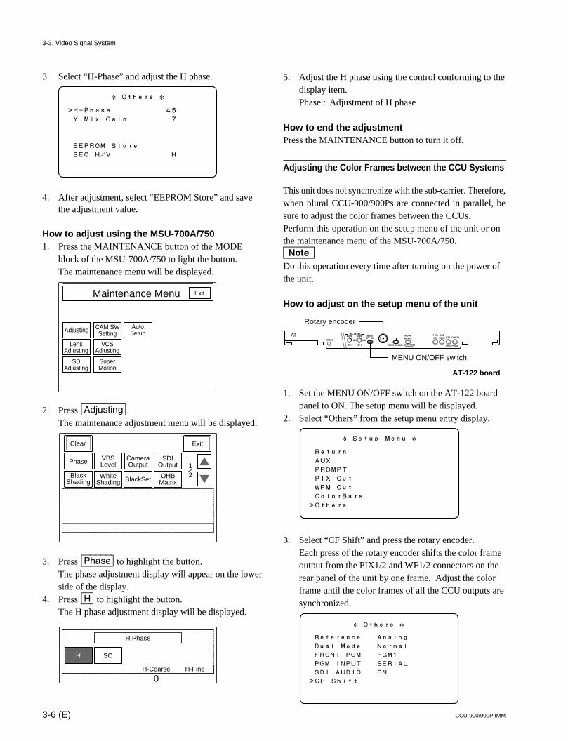
3. Select “H-Phase” and adjust the H phase.
4. After adjustment, select “EEPROM Store” and savethe adjustment value.
How to adjust using the MSU-700A/7501. Press the MAINTENANCE button of the MODE
block of the MSU-700A/750 to light the button.The maintenance menu will be displayed.
2. Press [Adjusting].The maintenance adjustment menu will be displayed.
3. Press [Phase] to highlight the button.The phase adjustment display will appear on the lowerside of the display.
4. Press [H] to highlight the button.The H phase adjustment display will be displayed.
Maintenance Menu
Adjusting CAM SWSetting
AutoSetup
Exit
LensAdjusting
VCSAdjusting
SDAdjusting
SuperMotion
Clear
Phase
BlackShading
VBSLevel
WhiteShading BlackSet
SDIOutput
Exit
12/
OHBMatrix
CameraOutput
SCH
H Phase
H-Coarse H-Fine
0
5. Adjust the H phase using the control conforming to thedisplay item.Phase : Adjustment of H phase
How to end the adjustmentPress the MAINTENANCE button to turn it off.
Adjusting the Color Frames between the CCU Systems
This unit does not synchronize with the sub-carrier. Therefore,when plural CCU-900/900Ps are connected in parallel, besure to adjust the color frames between the CCUs.Perform this operation on the setup menu of the unit or onthe maintenance menu of the MSU-700A/750.nDo this operation every time after turning on the power ofthe unit.
How to adjust on the setup menu of the unit
AT-122 board
1. Set the MENU ON/OFF switch on the AT-122 boardpanel to ON. The setup menu will be displayed.
2. Select “Others” from the setup menu entry display.
3. Select “CF Shift” and press the rotary encoder.Each press of the rotary encoder shifts the color frameoutput from the PIX1/2 and WF1/2 connectors on therear panel of the unit by one frame. Adjust the colorframe until the color frames of all the CCU outputs aresynchronized.
* Setup Menu *
Return
AUX
PROMPT
PIX Out
WFM Out
ColorBars
>Others
MIN
CH-1 CH-2
ON
ENTER CANCEL ENG PRODPRIVATE
OFFMIN
NORM NORMMIC LEVEL
POWER
MENU INCOMSELECT
PGMMIX
SIDETONE RTS
ENG PROD
CANCEL
MENU ON/OFF switch
Rotary encoder
* Others *
Reference Analog
Dual Mode Normal
FRONT PGM PGM1
PGM INPUT SERIAL
SDI AUDIO ON
>CF Shift
3-3. Video Signal System
* Others *
>H-Phase 45
Y-Mix Gain 7
EEPROM Store
SEQ H/V H

3-7 (E)CCU-900/900P IMM
How to adjust using the MSU-700A/7501. Press the MAINTENANCE button of the MODE
block of the MSU-700A/750 to light the button.The maintenance menu will be displayed.
2. Press [Adjusting].The maintenance adjustment menu will be displayed.
3. Press to display the maintenance adjustmentmenu 2/2.
4. Press [CF|Shift] once.The color frame output from the PIX1/2 and WF1/2connectors on the rear panel of the unit is shifted byone frame. Adjust the color frame until the colorframes of all the CCU outputs are synchronized.
CCU Monitor Output
4 : 3 Mod
4 : 3 Maker
CFShift
Mode LevelSkin Gate
Clear
MonitorOutput
Home
22/
Maintenance Menu
Adjusting CAM SWSetting
AutoSetup
Exit
LensAdjusting
VCSAdjusting
SDAdjusting
SuperMotion
Clear
Phase
BlackShading
VBSLevel
WhiteShading BlackSet
SDIOutput
Exit
12/
OHBMatrix
CameraOutput
3-3-4. Adjusting the Level of Signals forWaveform Monitor
The video output signal of this unit can be checked on thewaveform monitor connected to the WF output connector.Adjust the WF output signal level using the color-bar signal.In the system with the MSU-700A/750, CNU-700/500 andVCS-700, the video output signal can be checked on thewaveform monitor connected to the VCS-700. For moredetails, refer to the system manual or the VCS-700 mainte-nance manual.
Adjusting the WF Output Signal Level
AT-122 board
1. While pressing the rotary encoder on the AT-122board panel, set the MENU ON/OFF switch to ON.The engineering menu will be displayed.
2. Press the BAR button of the MSU-700A/750, RCP-740/741 or others and press the ENC button of theWAVEFORM MONITOR button (or the MONITORSELECT button) to display the color bars on thewaveform monitor.
3. Select “DA1” from the engineering menu entry display.
4. Select “WFM1 Gain” and adjust the color bar signal sothat it is within the specified levels.
5. Select “EEPROM Store” and save the adjustmentvalue.
MIN
CH-1 CH-2
ON
ENTER CANCEL ENG PRODPRIVATE
OFFMIN
NORM NORMMIC LEVEL
POWER
MENU INCOMSELECT
PGMMIX
SIDETONE RTS
ENG PROD
CANCEL
MENU ON/OFF switch
Rotary encoder
* Engineering Menu *
>DA1
DA2
DA3
Others
* DA1 *
PIX1 Gain 80
PIX1 DC A2
>WFM1 Gain 80
WFM1 DC A2
EEPROM Store
3-3. Video Signal System
3-8 (E) CCU-900/900P IMM
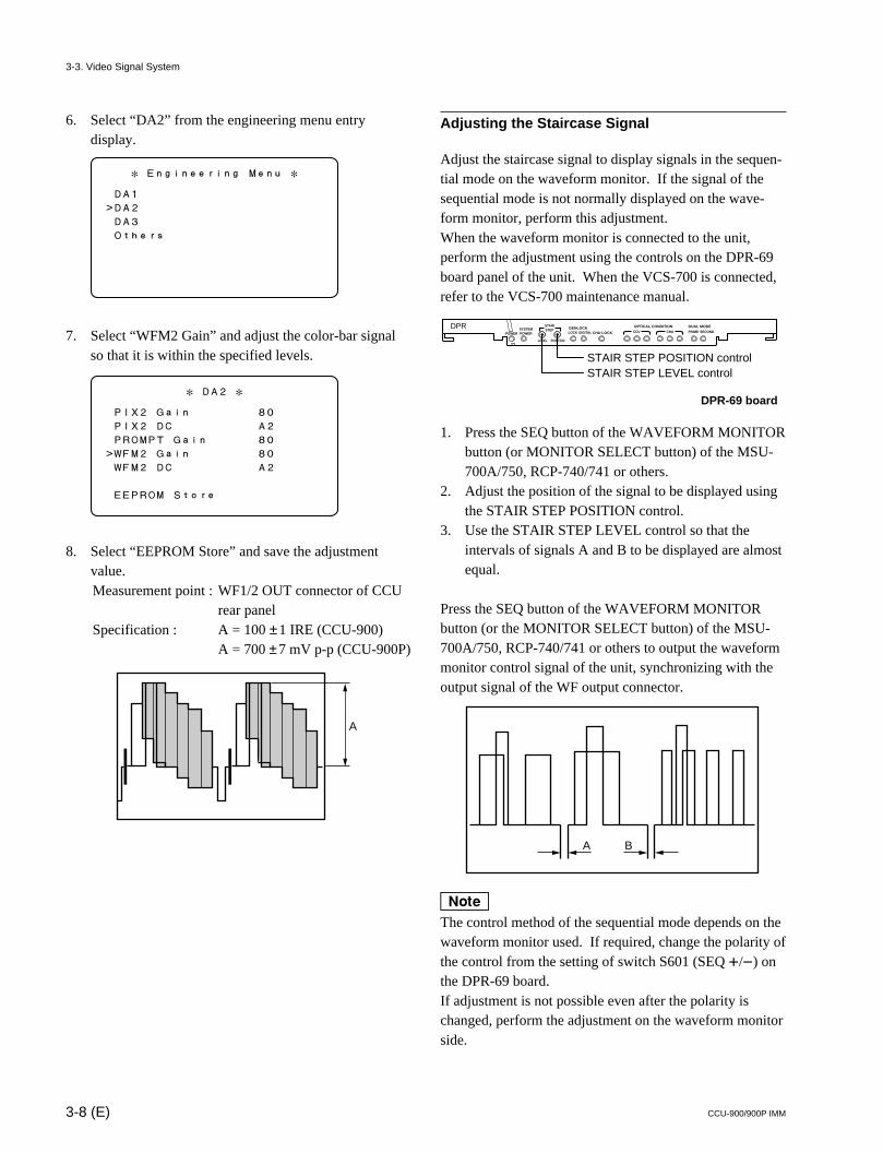
6. Select “DA2” from the engineering menu entrydisplay.
7. Select “WFM2 Gain” and adjust the color-bar signalso that it is within the specified levels.
8. Select “EEPROM Store” and save the adjustmentvalue.Measurement point : WF1/2 OUT connector of CCU
rear panelSpecification : A = 100 ±1 IRE (CCU-900)
A = 700 ±7 mV p-p (CCU-900P)
* Engineering Menu *
DA1
>DA2
DA3
Others
* DA2 *
PIX2 Gain 80
PIX2 DC A2
PROMPT Gain 80
>WFM2 Gain 80
WFM2 DC A2
EEPROM Store
A
Adjusting the Staircase Signal
Adjust the staircase signal to display signals in the sequen-tial mode on the waveform monitor. If the signal of thesequential mode is not normally displayed on the wave-form monitor, perform this adjustment.When the waveform monitor is connected to the unit,perform the adjustment using the controls on the DPR-69board panel of the unit. When the VCS-700 is connected,refer to the VCS-700 maintenance manual.
DPR-69 board
1. Press the SEQ button of the WAVEFORM MONITORbutton (or MONITOR SELECT button) of the MSU-700A/750, RCP-740/741 or others.
2. Adjust the position of the signal to be displayed usingthe STAIR STEP POSITION control.
3. Use the STAIR STEP LEVEL control so that theintervals of signals A and B to be displayed are almostequal.
Press the SEQ button of the WAVEFORM MONITORbutton (or the MONITOR SELECT button) of the MSU-700A/750, RCP-740/741 or others to output the waveformmonitor control signal of the unit, synchronizing with theoutput signal of the WF output connector.
nThe control method of the sequential mode depends on thewaveform monitor used. If required, change the polarity ofthe control from the setting of switch S601 (SEQ +/_) onthe DPR-69 board.If adjustment is not possible even after the polarity ischanged, perform the adjustment on the waveform monitorside.
POWERSYSTEMPOWER
DPR
LEVEL POSITION
STAIRSTEP GENLOCK
LOCK DIGITAL CHU LOCK CCU CHUOPTICAL CONDITION DUAL MODE
PRIME SECOND
STAIR STEP POSITION controlSTAIR STEP LEVEL control
A B
3-3. Video Signal System
3-9 (E)CCU-900/900P IMM
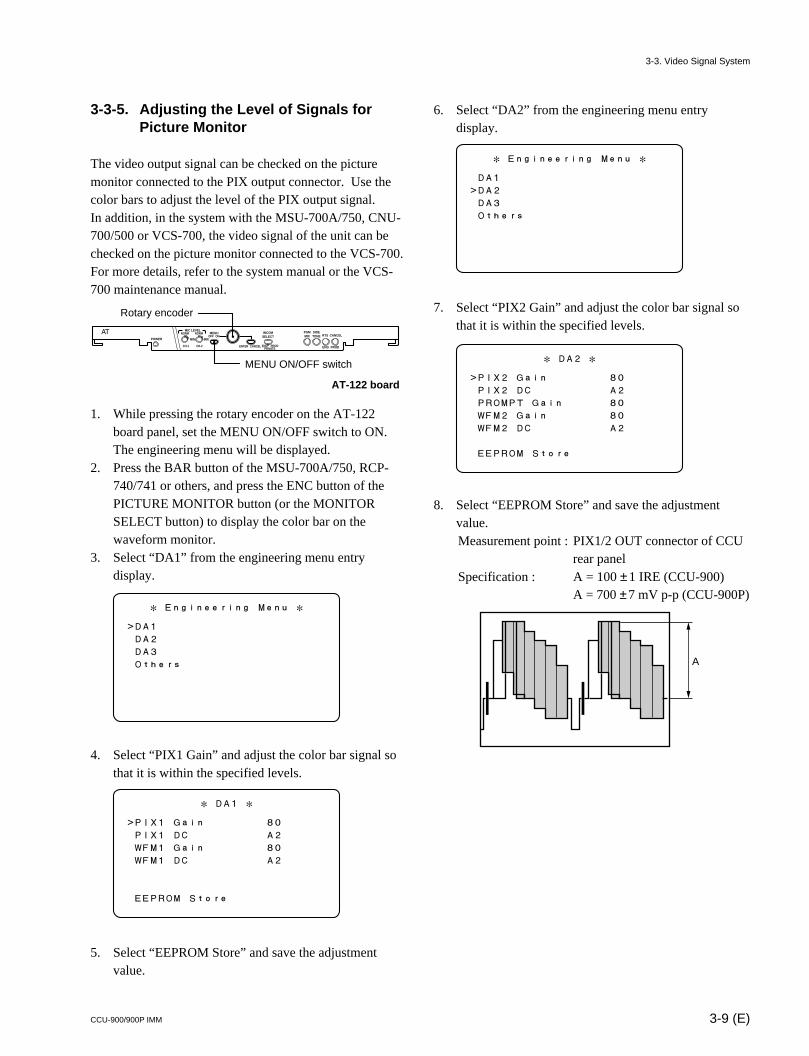
3-3-5. Adjusting the Level of Signals forPicture Monitor
The video output signal can be checked on the picturemonitor connected to the PIX output connector. Use thecolor bars to adjust the level of the PIX output signal.In addition, in the system with the MSU-700A/750, CNU-700/500 or VCS-700, the video signal of the unit can bechecked on the picture monitor connected to the VCS-700.For more details, refer to the system manual or the VCS-700 maintenance manual.
AT-122 board
1. While pressing the rotary encoder on the AT-122board panel, set the MENU ON/OFF switch to ON.The engineering menu will be displayed.
2. Press the BAR button of the MSU-700A/750, RCP-740/741 or others, and press the ENC button of thePICTURE MONITOR button (or the MONITORSELECT button) to display the color bar on thewaveform monitor.
3. Select “DA1” from the engineering menu entrydisplay.
4. Select “PIX1 Gain” and adjust the color bar signal sothat it is within the specified levels.
5. Select “EEPROM Store” and save the adjustmentvalue.
MIN
CH-1 CH-2
ON
ENTER CANCEL ENG PRODPRIVATE
OFFMIN
NORM NORMMIC LEVEL
POWER
MENU INCOMSELECT
PGMMIX
SIDETONE RTS
ENG PROD
CANCEL
MENU ON/OFF switch
Rotary encoder
A
* DA2 *
>PIX2 Gain 80
PIX2 DC A2
PROMPT Gain 80
WFM2 Gain 80
WFM2 DC A2
EEPROM Store
* DA1 *
>PIX1 Gain 80
PIX1 DC A2
WFM1 Gain 80
WFM1 DC A2
EEPROM Store
* Engineering Menu *
>DA1
DA2
DA3
Others
6. Select “DA2” from the engineering menu entrydisplay.
7. Select “PIX2 Gain” and adjust the color bar signal sothat it is within the specified levels.
8. Select “EEPROM Store” and save the adjustmentvalue.Measurement point : PIX1/2 OUT connector of CCU
rear panelSpecification : A = 100 ±1 IRE (CCU-900)
A = 700 ±7 mV p-p (CCU-900P)
* Engineering Menu *
DA1
>DA2
DA3
Others
3-3. Video Signal System
3-10 (E) CCU-900/900P IMM
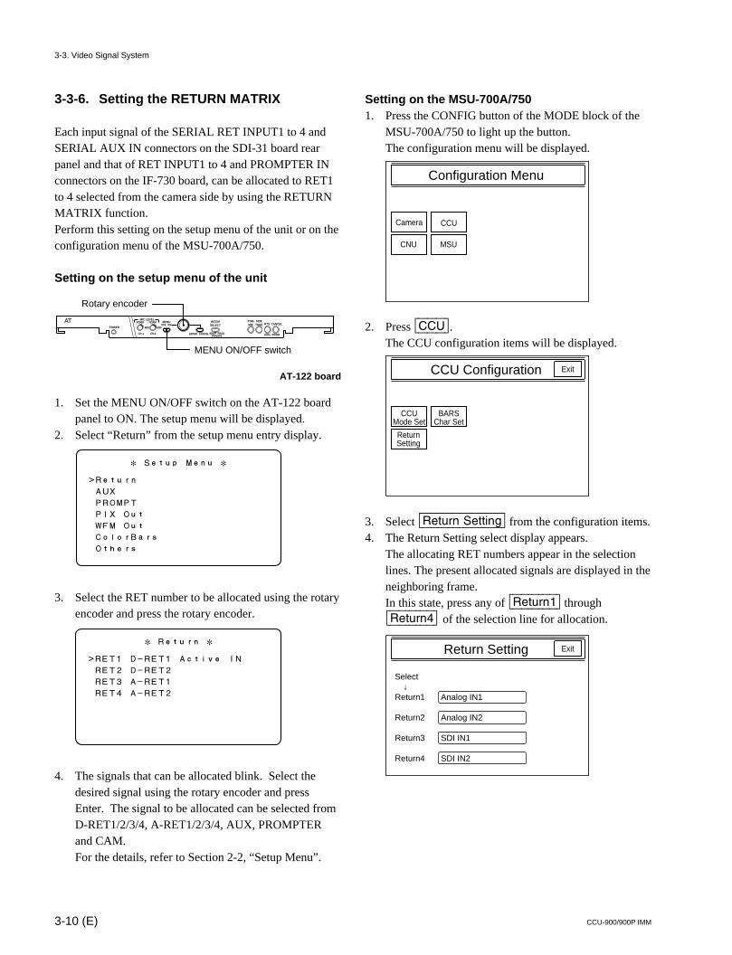
3-3-6. Setting the RETURN MATRIX
Each input signal of the SERIAL RET INPUT1 to 4 andSERIAL AUX IN connectors on the SDI-31 board rearpanel and that of RET INPUT1 to 4 and PROMPTER INconnectors on the IF-730 board, can be allocated to RET1to 4 selected from the camera side by using the RETURNMATRIX function.Perform this setting on the setup menu of the unit or on theconfiguration menu of the MSU-700A/750.
Setting on the setup menu of the unit
AT-122 board
1. Set the MENU ON/OFF switch on the AT-122 boardpanel to ON. The setup menu will be displayed.
2. Select “Return” from the setup menu entry display.
3. Select the RET number to be allocated using the rotaryencoder and press the rotary encoder.
4. The signals that can be allocated blink. Select thedesired signal using the rotary encoder and pressEnter. The signal to be allocated can be selected fromD-RET1/2/3/4, A-RET1/2/3/4, AUX, PROMPTERand CAM.For the details, refer to Section 2-2, “Setup Menu”.
Setting on the MSU-700A/7501. Press the CONFIG button of the MODE block of the
MSU-700A/750 to light up the button.The configuration menu will be displayed.
2. Press [CCU].The CCU configuration items will be displayed.
3. Select [Return|Setting] from the configuration items.4. The Return Setting select display appears.
The allocating RET numbers appear in the selectionlines. The present allocated signals are displayed in theneighboring frame.In this state, press any of [Return1] through[Return4] of the selection line for allocation.
3-3. Video Signal System
Configuration Menu
Camera CCU
CNU MSU
MIN
CH-1 CH-2
ON
ENTER CANCEL ENG PRODPRIVATE
OFFMIN
NORM NORMMIC LEVEL
POWER
MENU INCOMSELECT
PGMMIX
SIDETONE RTS
ENG PROD
CANCEL
MENU ON/OFF switch
Rotary encoder
* Setup Menu *
>Return
AUX
PROMPT
PIX Out
WFM Out
ColorBars
Others
* Return *
>RET1 D-RET1 Active IN
RET2 D-RET2
RET3 A-RET1
RET4 A-RET2
CCU Configuration
CCUMode Set
BARSChar Set
ReturnSetting
Exit
Return Setting
Select ↓Return1
Return2
Return3
Return4
Exit
Analog IN1
Analog IN2
SDI IN1
SDI IN2
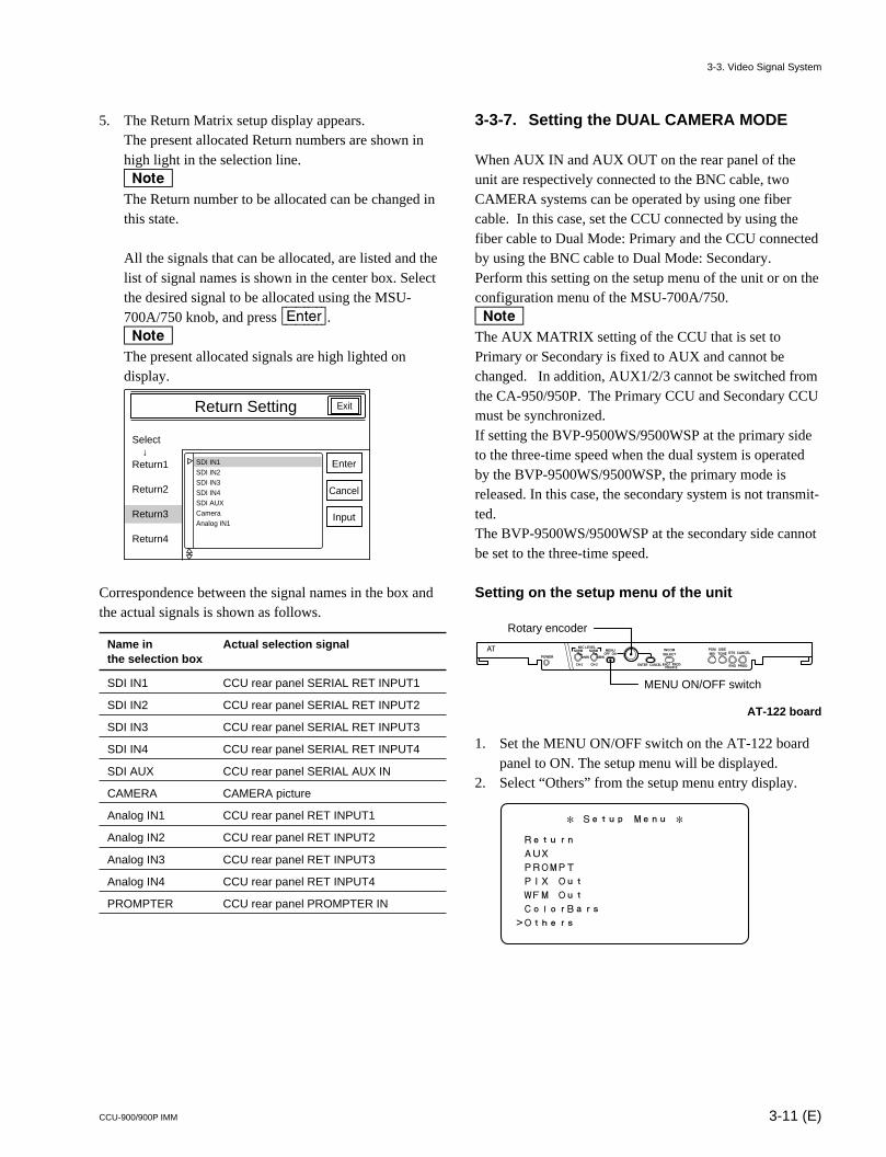
3-11 (E)CCU-900/900P IMM
5. The Return Matrix setup display appears.The present allocated Return numbers are shown inhigh light in the selection line.nThe Return number to be allocated can be changed inthis state.
All the signals that can be allocated, are listed and thelist of signal names is shown in the center box. Selectthe desired signal to be allocated using the MSU-700A/750 knob, and press [Enter].nThe present allocated signals are high lighted ondisplay.
Correspondence between the signal names in the box andthe actual signals is shown as follows.
Name in Actual selection signalthe selection box
SDI IN1 CCU rear panel SERIAL RET INPUT1
SDI IN2 CCU rear panel SERIAL RET INPUT2
SDI IN3 CCU rear panel SERIAL RET INPUT3
SDI IN4 CCU rear panel SERIAL RET INPUT4
SDI AUX CCU rear panel SERIAL AUX IN
CAMERA CAMERA picture
Analog IN1 CCU rear panel RET INPUT1
Analog IN2 CCU rear panel RET INPUT2
Analog IN3 CCU rear panel RET INPUT3
Analog IN4 CCU rear panel RET INPUT4
PROMPTER CCU rear panel PROMPTER IN
Return Setting
Select ↓Return1
Return2
Return3
Return4
Exit
Enter
Cancel
Input
SDI IN1SDI IN2SDI IN3SDI IN4SDI AUXCameraAnalog IN1
3-3. Video Signal System
3-3-7. Setting the DUAL CAMERA MODE
When AUX IN and AUX OUT on the rear panel of theunit are respectively connected to the BNC cable, twoCAMERA systems can be operated by using one fibercable. In this case, set the CCU connected by using thefiber cable to Dual Mode: Primary and the CCU connectedby using the BNC cable to Dual Mode: Secondary.Perform this setting on the setup menu of the unit or on theconfiguration menu of the MSU-700A/750.nThe AUX MATRIX setting of the CCU that is set toPrimary or Secondary is fixed to AUX and cannot bechanged. In addition, AUX1/2/3 cannot be switched fromthe CA-950/950P. The Primary CCU and Secondary CCUmust be synchronized.If setting the BVP-9500WS/9500WSP at the primary sideto the three-time speed when the dual system is operatedby the BVP-9500WS/9500WSP, the primary mode isreleased. In this case, the secondary system is not transmit-ted.The BVP-9500WS/9500WSP at the secondary side cannotbe set to the three-time speed.
Setting on the setup menu of the unit
AT-122 board
1. Set the MENU ON/OFF switch on the AT-122 boardpanel to ON. The setup menu will be displayed.
2. Select “Others” from the setup menu entry display.
MIN
CH-1 CH-2
ON
ENTER CANCEL ENG PRODPRIVATE
OFFMIN
NORM NORMMIC LEVEL
POWER
MENU INCOMSELECT
PGMMIX
SIDETONE RTS
ENG PROD
CANCEL
MENU ON/OFF switch
Rotary encoder
* Setup Menu *
Return
AUX
PROMPT
PIX Out
WFM Out
ColorBars
>Others
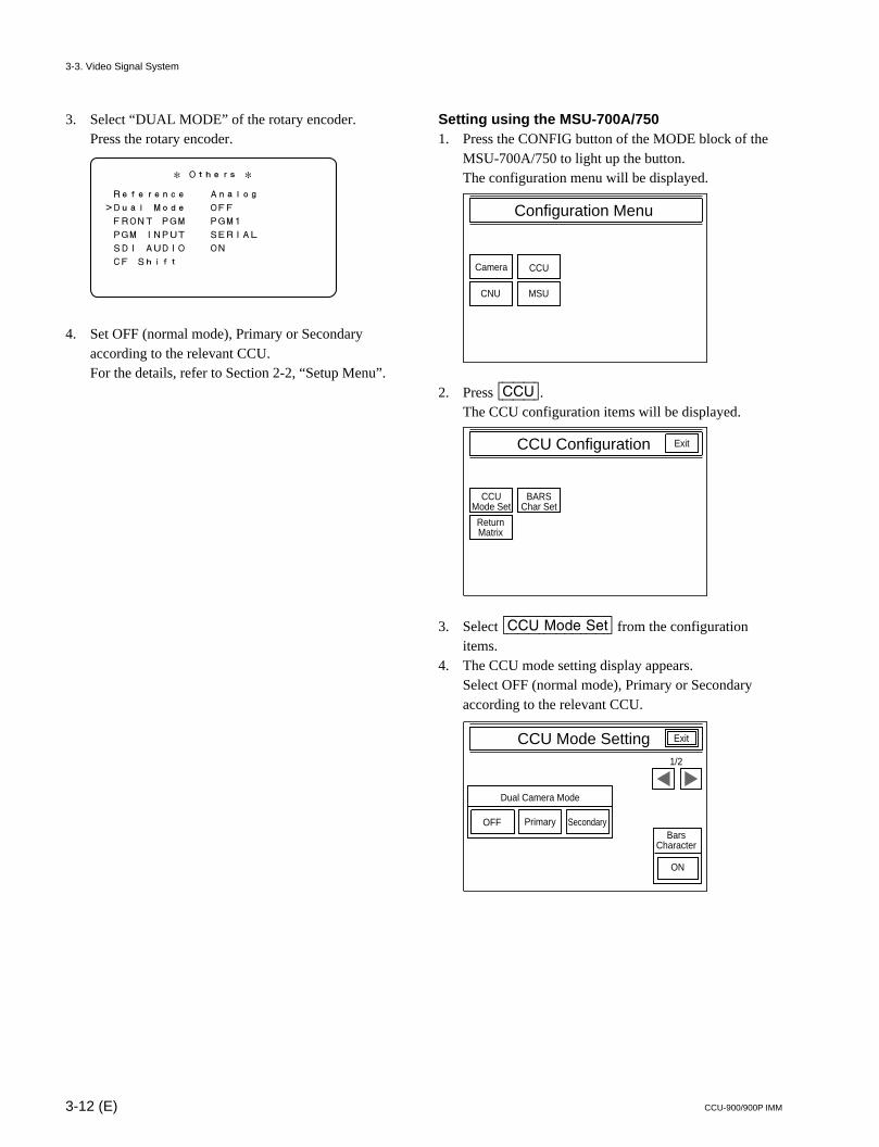
3-12 (E) CCU-900/900P IMM
3. Select “DUAL MODE” of the rotary encoder.Press the rotary encoder.
4. Set OFF (normal mode), Primary or Secondaryaccording to the relevant CCU.For the details, refer to Section 2-2, “Setup Menu”.
Setting using the MSU-700A/7501. Press the CONFIG button of the MODE block of the
MSU-700A/750 to light up the button.The configuration menu will be displayed.
2. Press [CCU].The CCU configuration items will be displayed.
3. Select [CCU|Mode|Set] from the configurationitems.
4. The CCU mode setting display appears.Select OFF (normal mode), Primary or Secondaryaccording to the relevant CCU.
3-3. Video Signal System
* Others *
Reference Analog
>Dual Mode OFF
FRONT PGM PGM1
PGM INPUT SERIAL
SDI AUDIO ON
CF Shift
Configuration Menu
Camera CCU
CNU MSU
CCU Configuration
CCUMode Set
BARSChar Set
ReturnMatrix
Exit
CCU Mode Setting
Secondary
Exit
OFF Primary
Dual Camera Mode
ON
BarsCharacter
1/2
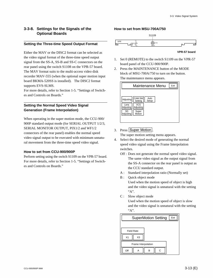
3-13 (E)CCU-900/900P IMM
3-3-8. Settings for the Signals of theOptional Boards
Setting the Three-time Speed Output Format
Either the MAV or the DISC2 format can be selected asthe video signal format of the three-time speed outputsignal from the SS-A, SS-B and SS-C connectors on therear panel using the switch S1108 on the VPR-57 board.The MAV format suits to the multi-access video diskrecorder MAV-555 (when the optional super motion inputboard BKMA-520SS is installed). The DISC2 formatsupports EVS-SLMS.For more details, refer to Section 1-5. “Settings of Switch-es and Controls on Boards.”
Setting the Normal Speed Video SignalGeneration (Frame Interpolation)
When operating in the super motion mode, the CCU-900/900P standard output mode (for SERIAL OUTPUT 1/2/3,SERIAL MONITOR OUTPUT, PIX1/2 and WF1/2connectors of the rear panel) enables the normal speedvideo signal output to be executed with minimum unnatu-ral movement from the three-time speed video signal.
How to set from CCU-900/900PPerform setting using the switch S1109 on the VPR-57 board.For more details, refer to Section 1-5. “Settings of Switch-es and Controls on Boards.”
3-3. Video Signal System
Maintenance Menu
Adjusting CAM SWSetting
AutoSetup
Exit
LensAdjusting
VCSAdjusting
SDAdjusting
SuperMotion
SuperMotion Setting Exit
X1 X3
Field Rate
Frame Interpolation
Off A B C
POWER ENABLE
VPR
REMOTE
LOCAL
S1109
How to set from MSU-700A/750
VPR-57 board
1. Set 0 (REMOTE) to the switch S1109 on the VPR-57board panel of the CCU-900/900P.
2. Press the MAINTENANCE button of the MODEblock of MSU-700A/750 to turn on the button.The maintenance menu appears.
3. Press [Super|Motion].The super motion setting menu appears.
4. Select the desired mode of generating the normalspeed video signal using the Frame Interpolationswitches.Off : Does not generate the normal speed video signal.
The same video signal as the output signal fromthe SS-A connector on the rear panel is output asthe CCU standard output.
A : Standard interpolation ratio (Normally set)B : Quick object mode
Used when the motion speed of object is highand the video signal is unnatural with the setting“A”.
C : Slow object modeUsed when the motion speed of object is slowand the video signal is unnatural with the setting“A”.
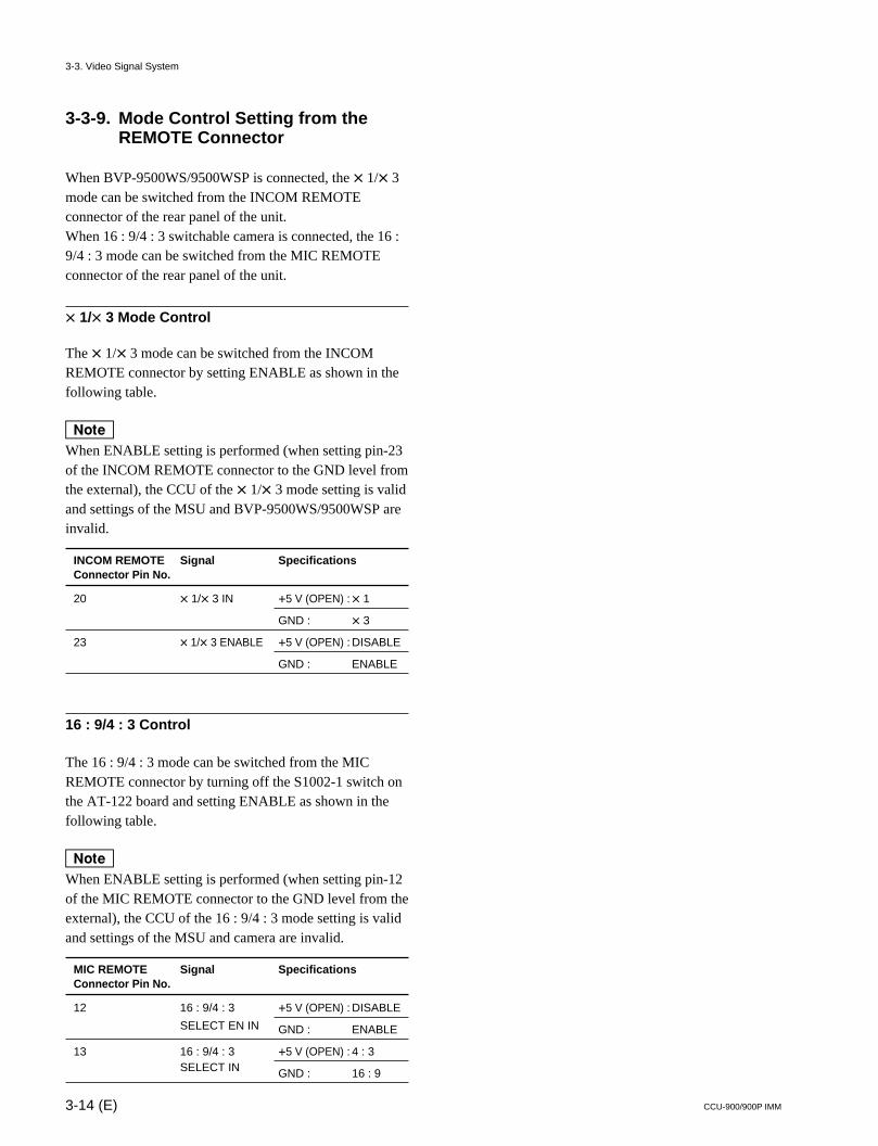
3-14 (E) CCU-900/900P IMM
3-3-9. Mode Control Setting from theREMOTE Connector
When BVP-9500WS/9500WSP is connected, the x 1/x 3mode can be switched from the INCOM REMOTEconnector of the rear panel of the unit.When 16 : 9/4 : 3 switchable camera is connected, the 16 :9/4 : 3 mode can be switched from the MIC REMOTEconnector of the rear panel of the unit.
x 1/x 3 Mode Control
The x 1/x 3 mode can be switched from the INCOMREMOTE connector by setting ENABLE as shown in thefollowing table.
nWhen ENABLE setting is performed (when setting pin-23of the INCOM REMOTE connector to the GND level fromthe external), the CCU of the x 1/x 3 mode setting is validand settings of the MSU and BVP-9500WS/9500WSP areinvalid.
INCOM REMOTE Signal SpecificationsConnector Pin No.
20 x 1/x 3 IN +5 V (OPEN) :x 1
GND : x 3
23 x 1/x 3 ENABLE +5 V (OPEN) : DISABLE
GND : ENABLE
16 : 9/4 : 3 Control
The 16 : 9/4 : 3 mode can be switched from the MICREMOTE connector by turning off the S1002-1 switch onthe AT-122 board and setting ENABLE as shown in thefollowing table.
nWhen ENABLE setting is performed (when setting pin-12of the MIC REMOTE connector to the GND level from theexternal), the CCU of the 16 : 9/4 : 3 mode setting is validand settings of the MSU and camera are invalid.
MIC REMOTE Signal SpecificationsConnector Pin No.
12 16 : 9/4 : 3 +5 V (OPEN) : DISABLE
SELECT EN IN GND : ENABLE
13 16 : 9/4 : 3 +5 V (OPEN) : 4 : 3SELECT IN GND : 16 : 9
3-3. Video Signal System
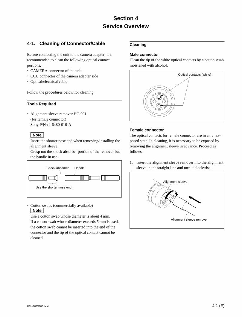
4-1 (E)CCU-900/900P IMM
Section 4Service Overview
4-1. Cleaning of Connector/Cable
Before connecting the unit to the camera adapter, it isrecommended to clean the following optical contactportions.. CAMERA connector of the unit. CCU connector of the camera adapter side. Optical/electrical cable
Follow the procedures below for cleaning.
Tools Required
. Alignment sleeve remover HC-001(for female connector)Sony P/N : J-6480-010-A
nInsert the shorter nose end when removing/installing thealignment sleeve.Grasp not the shock absorber portion of the remover butthe handle in use.
. Cotton swabs (commercially available)nUse a cotton swab whose diameter is about 4 mm.If a cotton swab whose diameter exceeds 5 mm is used,the cotton swab cannot be inserted into the end of theconnector and the tip of the optical contact cannot becleaned.
Use the shorter nose end.
Shock absorber Handle
Cleaning
Male connectorClean the tip of the white optical contacts by a cotton swabmoistened with alcohol.
Female connectorThe optical contacts for female connector are in an unex-posed state. In cleaning, it is necessary to be exposed byremoving the alignment sleeve in advance. Proceed asfollows.
1. Insert the alignment sleeve remover into the alignmentsleeve in the straight line and turn it clockwise.
Optical contacts (white)
Alignment sleeve
Alignment sleeve remover
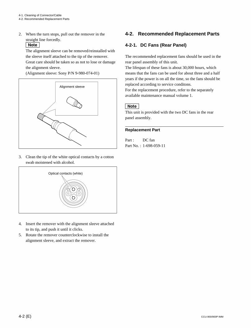
4-2 (E) CCU-900/900P IMM
2. When the turn stops, pull out the remover in thestraight line forcedly.nThe alignment sleeve can be removed/reinstalled withthe sleeve itself attached to the tip of the remover.Great care should be taken so as not to lose or damagethe alignment sleeve.(Alignment sleeve: Sony P/N 9-980-074-01)
3. Clean the tip of the white optical contacts by a cottonswab moistened with alcohol.
4. Insert the remover with the alignment sleeve attachedto its tip, and push it until it clicks.
5. Rotate the remover counterclockwise to install thealignment sleeve, and extract the remover.
Alignment sleeve
Optical contacts (white)
4-2. Recommended Replacement Parts
4-2-1. DC Fans (Rear Panel)
The recommended replacement fans should be used in therear panel assembly of this unit.The lifespan of these fans is about 30,000 hours, whichmeans that the fans can be used for about three and a halfyears if the power is on all the time, so the fans should bereplaced according to service conditons.For the replacement procedure, refer to the separatelyavailable maintenance manual volume 1.
nThis unit is provided with the two DC fans in the rearpanel assembly.
Replacement Part
Part : DC fanPart No. : 1-698-059-11
4-1. Cleaning of Connector/Cable4-2. Recommended Replacement Parts
CCU-900/900P IMM
The material contained in this manual consists ofinformation that is the property of Sony Corporation.Sony Corporation expressly prohibits the duplication ofany portion of this manual or the use thereof for anypurpose other than the operation or maintenance of theequipment described in this manual without the expresswritten permission of Sony Corporation.
Le matériel contenu dans ce manuel consiste eninformations qui sont la propriété de Sony Corporation.Sony Corporation interdit formellement la copie dequelque partie que ce soit de ce manuel ou son emploipour tout autre but que des opérations ou entretiens del’équipement à moins d’une permission écrite de SonyCorporation.
Das in dieser Anleitung enthaltene Material besteht ausInformationen, die Eigentum der Sony Corporation sind.Die Sony Corporation untersagt ausdrücklich dieVervielfältigung jeglicher Teile dieser Anleitung oder denGebrauch derselben für irgendeinen anderen Zweck alsdie Bedienung oder Wartung der in dieser Anleitungbeschriebenen Ausrüstung ohne ausdrücklicheschriftliche Erlaubnis der Sony Corporation.

Printed in Japan
Sony Corporation 2000. 9 16
Communication System Solutions Network Company ©2000
CCU-900 (J, UC)
CCU-900P (CE)
BKP-9330 (SY) J, E
3-204-336-03