
Cambridge International Examinations Cambridge ... and Technology...Cambridge International...
20
This document consists of 19 printed pages and 1 blank page. DC (CW/SW) 115768/1 © UCLES 2016 [Turn over Cambridge International Examinations Cambridge International General Certificate of Secondary Education *7189222356* DESIGN AND TECHNOLOGY 0445/41 Paper 4 Systems and Control October/November 2016 1 hour Candidates answer on the Question Paper. No Additional Materials are required. READ THESE INSTRUCTIONS FIRST Write your Centre number, candidate number and name on all the work you hand in. Write in dark blue or black pen. You may use an HB pencil for any diagrams or graphs. Do not use staples, paper clips, glue or correction fluid. DO NOT WRITE IN ANY BARCODES. Section A Answer all questions in this section. Section B Answer one question in this section. You may use a calculator. At the end of the examination, fasten all your work securely together. The number of marks is given in brackets [ ] at the end of each question or part question. The total of the marks for this paper is 50.
Transcript of Cambridge International Examinations Cambridge ... and Technology...Cambridge International...

This document consists of 19 printed pages and 1 blank page.
DC (CW/SW) 115768/1© UCLES 2016 [Turn over
Cambridge International ExaminationsCambridge International General Certificate of Secondary Education
*7189222356*
DESIGN AND TECHNOLOGY 0445/41
Paper 4 Systems and Control October/November 2016
1 hour
Candidates answer on the Question Paper.
No Additional Materials are required.
READ THESE INSTRUCTIONS FIRST
Write your Centre number, candidate number and name on all the work you hand in.Write in dark blue or black pen.You may use an HB pencil for any diagrams or graphs.Do not use staples, paper clips, glue or correction fluid.DO NOT WRITE IN ANY BARCODES.
Section AAnswer all questions in this section.
Section BAnswer one question in this section.
You may use a calculator.
At the end of the examination, fasten all your work securely together.The number of marks is given in brackets [ ] at the end of each question or part question.The total of the marks for this paper is 50.
2
0445/41/O/N/16© UCLES 2016
Section A
Answer all questions in this section.
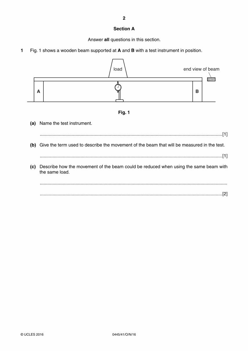
1 Fig. 1 shows a wooden beam supported at A and B with a test instrument in position.
end view of beamload
A B
Fig. 1
(a) Name the test instrument.
...............................................................................................................................................[1]
(b) Give the term used to describe the movement of the beam that will be measured in the test.
...............................................................................................................................................[1]
(c) Describe how the movement of the beam could be reduced when using the same beam with the same load.
...................................................................................................................................................
...............................................................................................................................................[2]
3
0445/41/O/N/16© UCLES 2016 [Turn over
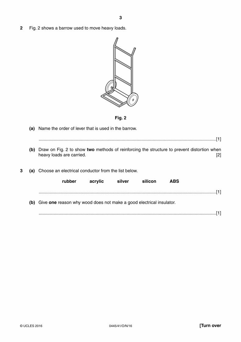
2 Fig. 2 shows a barrow used to move heavy loads.
Fig. 2
(a) Name the order of lever that is used in the barrow.
...............................................................................................................................................[1]
(b) Draw on Fig. 2 to show two methods of reinforcing the structure to prevent distortion when heavy loads are carried. [2]
3 (a) Choose an electrical conductor from the list below.
rubber acrylic silver silicon ABS
...............................................................................................................................................[1]
(b) Give one reason why wood does not make a good electrical insulator.
...............................................................................................................................................[1]
4
0445/41/O/N/16© UCLES 2016
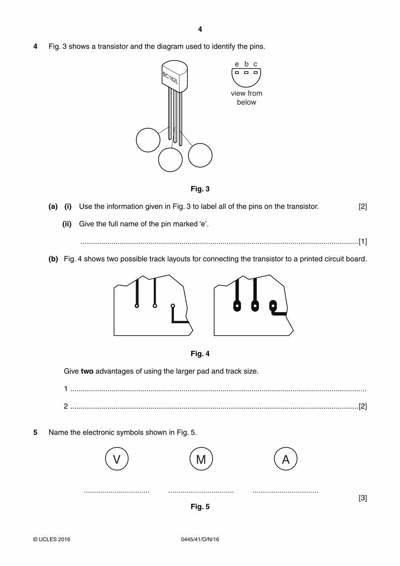
4 Fig. 3 shows a transistor and the diagram used to identify the pins.
view frombelow
e b c
Fig. 3
(a) (i) Use the information given in Fig. 3 to label all of the pins on the transistor. [2]
(ii) Give the full name of the pin marked ‘e’.
.......................................................................................................................................[1]
(b) Fig. 4 shows two possible track layouts for connecting the transistor to a printed circuit board.
Fig. 4
Give two advantages of using the larger pad and track size.
1 ................................................................................................................................................
2 ............................................................................................................................................[2]
5 Name the electronic symbols shown in Fig. 5.
V
................................
M
................................
A
................................ [3]
Fig. 5
5
0445/41/O/N/16© UCLES 2016 [Turn over
6 Name three power sources used to drive mechanical systems.
1 .......................................................................................................................................................
2 .......................................................................................................................................................
3 ...................................................................................................................................................[3]
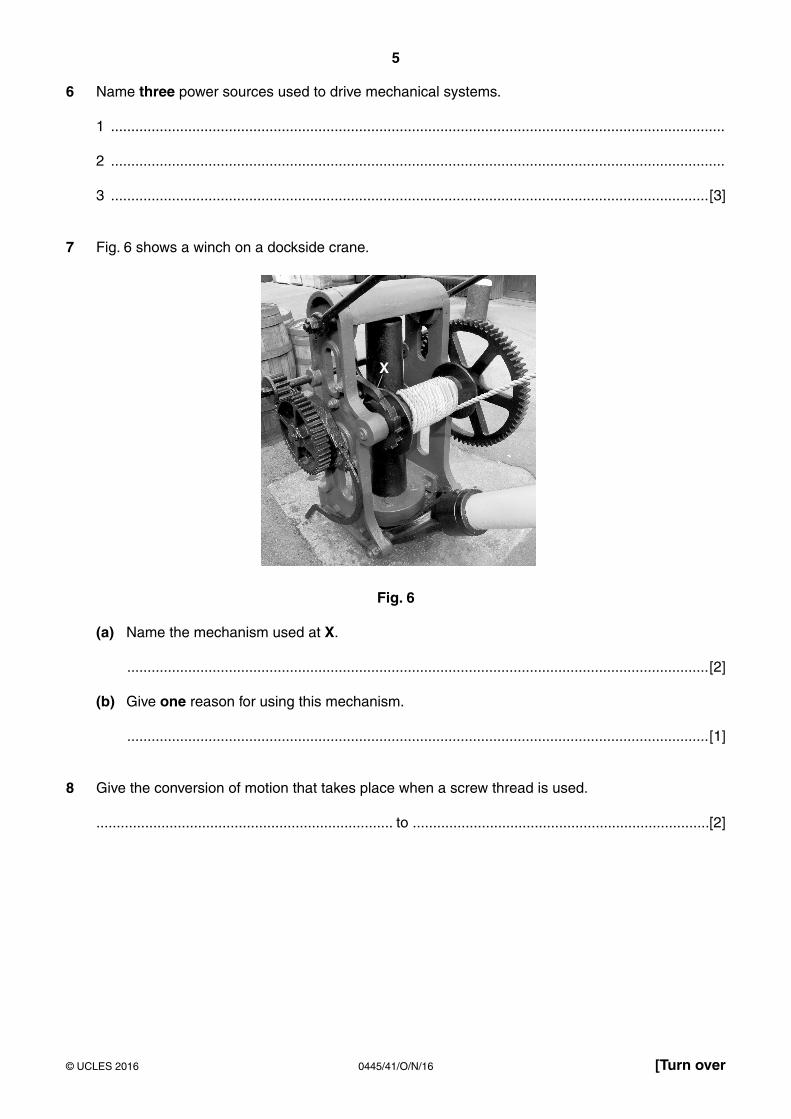
7 Fig. 6 shows a winch on a dockside crane.
X
Fig. 6
(a) Name the mechanism used at X.
...............................................................................................................................................[2]
(b) Give one reason for using this mechanism.
...............................................................................................................................................[1]
8 Give the conversion of motion that takes place when a screw thread is used.
......................................................................... to .........................................................................[2]
6
0445/41/O/N/16© UCLES 2016
Section B
Answer one question in this section.
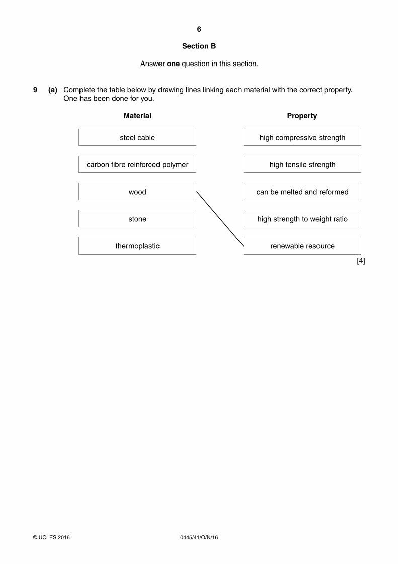
9 (a) Complete the table below by drawing lines linking each material with the correct property. One has been done for you.
Material Property
steel cable
high compressive strength
carbon fibre reinforced polymer
high tensile strength
wood
can be melted and reformed
stone
high strength to weight ratio
thermoplastic
renewable resource
[4]
7
0445/41/O/N/16© UCLES 2016 [Turn over
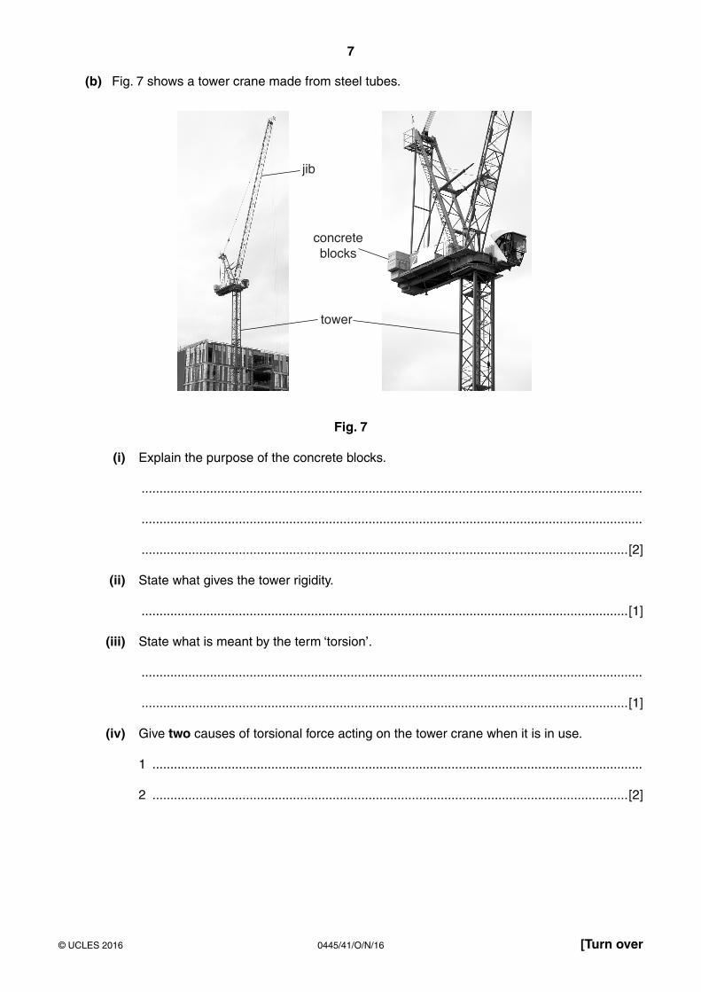
(b) Fig. 7 shows a tower crane made from steel tubes.
jib
tower
concreteblocks
Fig. 7
(i) Explain the purpose of the concrete blocks.
...........................................................................................................................................
...........................................................................................................................................
.......................................................................................................................................[2]
(ii) State what gives the tower rigidity.
.......................................................................................................................................[1]
(iii) State what is meant by the term ‘torsion’.
...........................................................................................................................................
.......................................................................................................................................[1]
(iv) Give two causes of torsional force acting on the tower crane when it is in use.
1 ........................................................................................................................................
2 ....................................................................................................................................[2]
8
0445/41/O/N/16© UCLES 2016
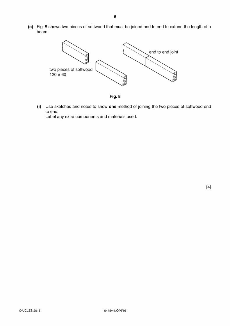
(c) Fig. 8 shows two pieces of softwood that must be joined end to end to extend the length of a beam.
end to end joint
two pieces of softwood120 × 60
Fig. 8
(i) Use sketches and notes to show one method of joining the two pieces of softwood end to end.
Label any extra components and materials used.
[4]
9
0445/41/O/N/16© UCLES 2016 [Turn over
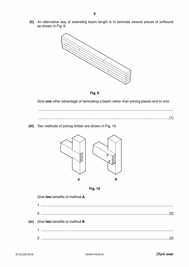
(ii) An alternative way of extending beam length is to laminate several pieces of softwoodas shown in Fig. 9.
Fig. 9
Give one other advantage of laminating a beam rather than joining pieces end to end.
...........................................................................................................................................
.......................................................................................................................................[1]
(iii) Two methods of joining timber are shown in Fig. 10.
A B
Fig. 10
Give two benefits of method A.
1 ........................................................................................................................................
2 ....................................................................................................................................[2]
(iv) Give two benefits of method B.
1 ........................................................................................................................................
2 ....................................................................................................................................[2]
10
0445/41/O/N/16© UCLES 2016
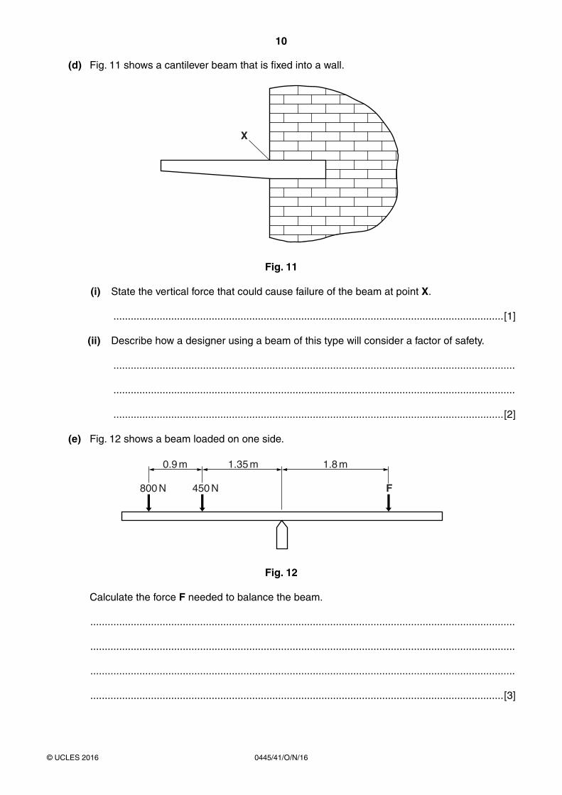
(d) Fig. 11 shows a cantilever beam that is fixed into a wall.
X
Fig. 11
(i) State the vertical force that could cause failure of the beam at point X.
.......................................................................................................................................[1]
(ii) Describe how a designer using a beam of this type will consider a factor of safety.
...........................................................................................................................................
...........................................................................................................................................
.......................................................................................................................................[2]
(e) Fig. 12 shows a beam loaded on one side.
0.9 m
800 N 450 N F
1.35 m 1.8 m
Fig. 12
Calculate the force F needed to balance the beam.
...................................................................................................................................................
...................................................................................................................................................
...................................................................................................................................................
...............................................................................................................................................[3]
11
0445/41/O/N/16© UCLES 2016 [Turn over
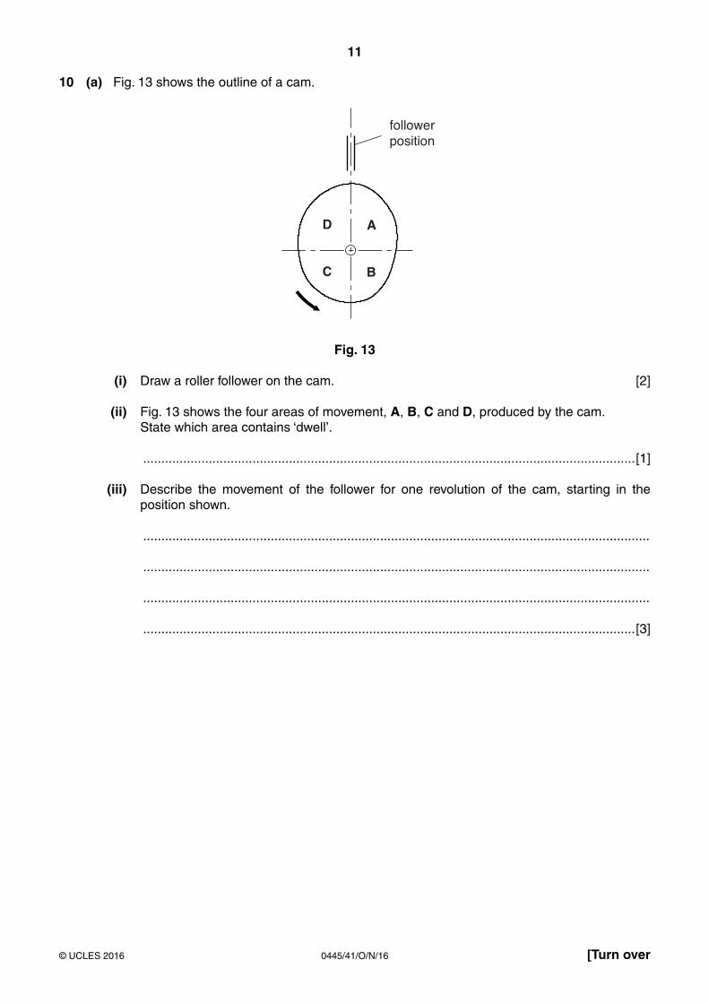
10 (a) Fig. 13 shows the outline of a cam.
followerposition
D A
C B
Fig. 13
(i) Draw a roller follower on the cam. [2]
(ii) Fig. 13 shows the four areas of movement, A, B, C and D, produced by the cam. State which area contains ‘dwell’.
.......................................................................................................................................[1]
(iii) Describe the movement of the follower for one revolution of the cam, starting in the position shown.
...........................................................................................................................................
...........................................................................................................................................
...........................................................................................................................................
.......................................................................................................................................[3]
12
0445/41/O/N/16© UCLES 2016
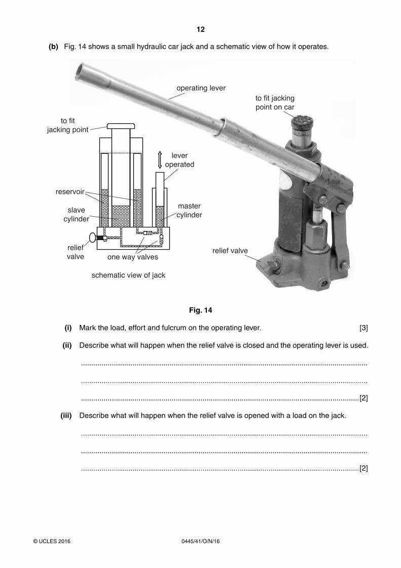
(b) Fig. 14 shows a small hydraulic car jack and a schematic view of how it operates.
mastercylinder
leveroperated
operating leverto fit jackingpoint on car
relief valve
to fitjacking point
reservoir
slavecylinder
reliefvalve one way valves
schematic view of jack
Fig. 14
(i) Mark the load, effort and fulcrum on the operating lever. [3]
(ii) Describe what will happen when the relief valve is closed and the operating lever is used.
...........................................................................................................................................
...........................................................................................................................................
.......................................................................................................................................[2]
(iii) Describe what will happen when the relief valve is opened with a load on the jack.
...........................................................................................................................................
...........................................................................................................................................
.......................................................................................................................................[2]
13
0445/41/O/N/16© UCLES 2016 [Turn over
(iv) Give two reasons why a pneumatic system would not be suitable for use in a car jack.
1 ........................................................................................................................................
2 ....................................................................................................................................[2]
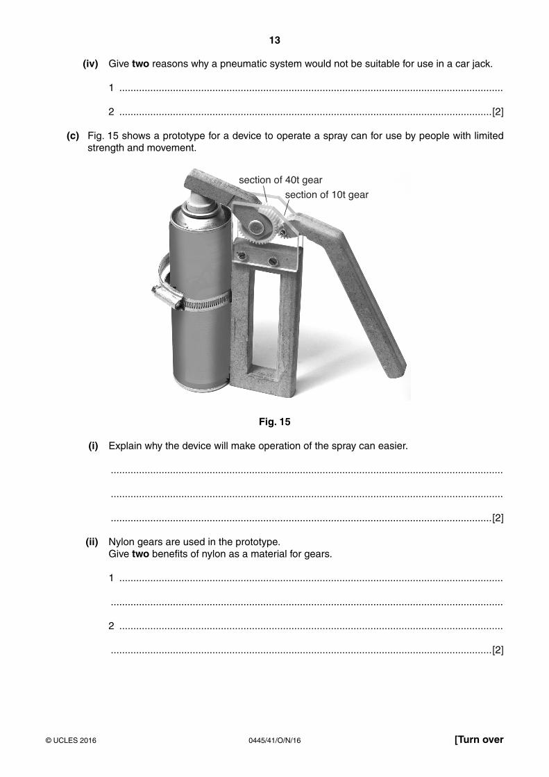
(c) Fig. 15 shows a prototype for a device to operate a spray can for use by people with limited strength and movement.
section of 40t gear
section of 10t gear
Fig. 15
(i) Explain why the device will make operation of the spray can easier.
...........................................................................................................................................
...........................................................................................................................................
.......................................................................................................................................[2]
(ii) Nylon gears are used in the prototype. Give two benefits of nylon as a material for gears.
1 ........................................................................................................................................
...........................................................................................................................................
2 ........................................................................................................................................
.......................................................................................................................................[2]
14
0445/41/O/N/16© UCLES 2016
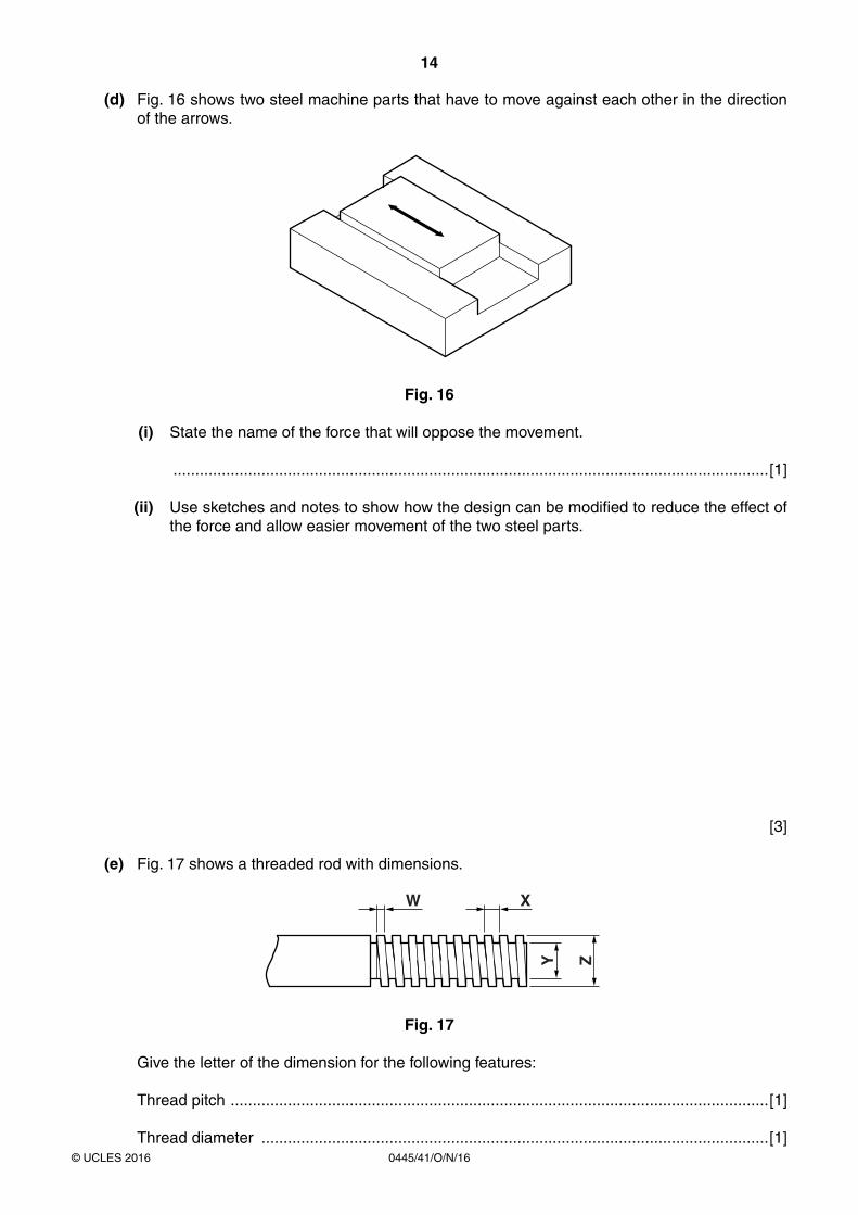
(d) Fig. 16 shows two steel machine parts that have to move against each other in the direction of the arrows.
Fig. 16
(i) State the name of the force that will oppose the movement.
.......................................................................................................................................[1]
(ii) Use sketches and notes to show how the design can be modified to reduce the effect of the force and allow easier movement of the two steel parts.
[3]
(e) Fig. 17 shows a threaded rod with dimensions.
W X
Y Z
Fig. 17
Give the letter of the dimension for the following features:
Thread pitch ..........................................................................................................................[1]
Thread diameter ...................................................................................................................[1]
15
0445/41/O/N/16© UCLES 2016 [Turn over
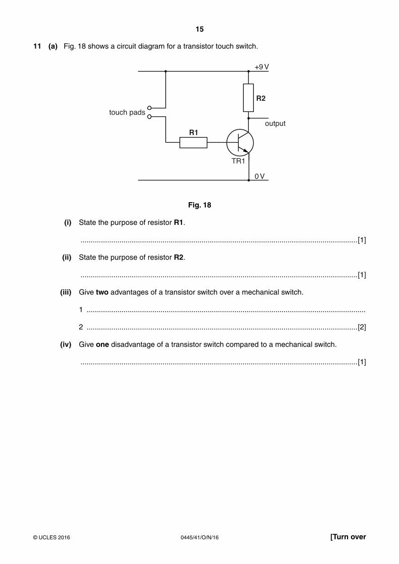
11 (a) Fig. 18 shows a circuit diagram for a transistor touch switch.
+9 V
0 V
TR1
output
touch pads
R2
R1
Fig. 18
(i) State the purpose of resistor R1.
.......................................................................................................................................[1]
(ii) State the purpose of resistor R2.
.......................................................................................................................................[1]
(iii) Give two advantages of a transistor switch over a mechanical switch.
1 ........................................................................................................................................
2 ....................................................................................................................................[2]
(iv) Give one disadvantage of a transistor switch compared to a mechanical switch.
.......................................................................................................................................[1]

16
0445/41/O/N/16© UCLES 2016
(v) Fig. 19 shows the colour bands on resistor R2. The resistor value is 15 kΩ 5% tolerance. Use the table to complete the colours on the bands of resistor R2.
R2...............................
..............................................................
...............................
First Band Second Band Multiplier Band Tolerance
SILVER ± 10%
GOLD ± 5%
BLACK – 0 BLACK – 0 BLACK – 0
BROWN – 1 BROWN – 1 BROWN – 1 BROWN ± 1%
RED – 2 RED – 2 RED – 2 RED ± 2%
ORANGE – 3 ORANGE – 3 ORANGE – 3
YELLOW – 4 YELLOW – 4 YELLOW – 4
GREEN – 5 GREEN – 5 GREEN – 5
BLUE – 6 BLUE – 6 BLUE – 6
VIOLET – 7 VIOLET – 7 VIOLET – 7
GREY – 8 GREY – 8 GREY – 8
WHITE – 9 WHITE – 9 WHITE – 9
[4]Fig. 19
17
0445/41/O/N/16© UCLES 2016 [Turn over
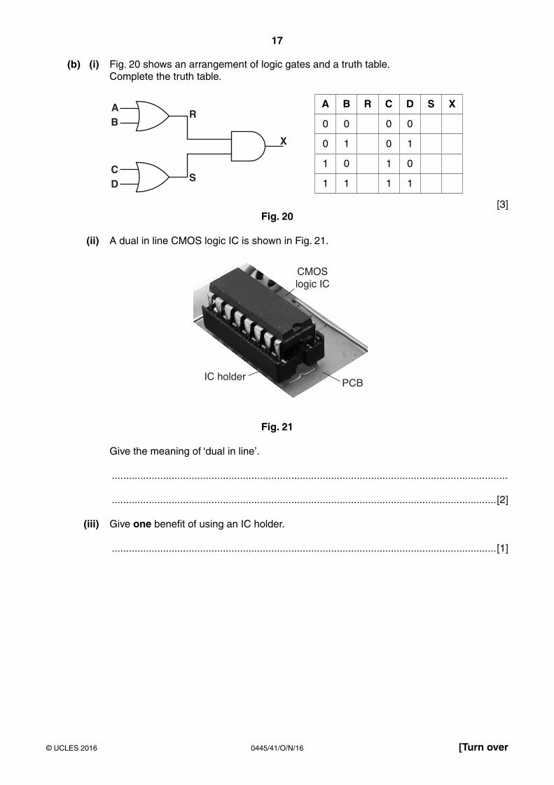
(b) (i) Fig. 20 shows an arrangement of logic gates and a truth table. Complete the truth table.
AR
S
X
B
CD
A B R C D S X
0 0 0 0
0 1 0 1
1 0 1 0
1 1 1 1
[3]Fig. 20
(ii) A dual in line CMOS logic IC is shown in Fig. 21.
CMOSlogic IC
PCBIC holder
Fig. 21
Give the meaning of ‘dual in line’.
...........................................................................................................................................
.......................................................................................................................................[2]
(iii) Give one benefit of using an IC holder.
.......................................................................................................................................[1]
18
0445/41/O/N/16© UCLES 2016
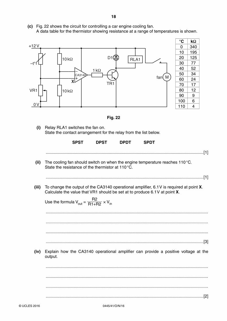
(c) Fig. 22 shows the circuit for controlling a car engine cooling fan. A data table for the thermistor showing resistance at a range of temperatures is shown.
M
D1
TR1
1 kCA3140–
+
10 k
10 k
RLA1
fanX
+12 V
0 V
VR1
–t°
°C kΩ0 340
10 19520 12530 7740 5250 3460 2470 1780 1290 9100 6110 4
Fig. 22
(i) Relay RLA1 switches the fan on. State the contact arrangement for the relay from the list below.
SPST DPST DPDT SPDT
.......................................................................................................................................[1]
(ii) The cooling fan should switch on when the engine temperature reaches 110 °C. State the resistance of the thermistor at 110 °C.
.......................................................................................................................................[1]
(iii) To change the output of the CA3140 operational amplifier, 6.1 V is required at point X. Calculate the value that VR1 should be set at to produce 6.1 V at point X.
Use the formula Vout = R2
R1+R2 × Vin
...........................................................................................................................................
...........................................................................................................................................
...........................................................................................................................................
.......................................................................................................................................[3]
(iv) Explain how the CA3140 operational amplifier can provide a positive voltage at the output.
...........................................................................................................................................
...........................................................................................................................................
...........................................................................................................................................
.......................................................................................................................................[2]
19
0445/41/O/N/16© UCLES 2016
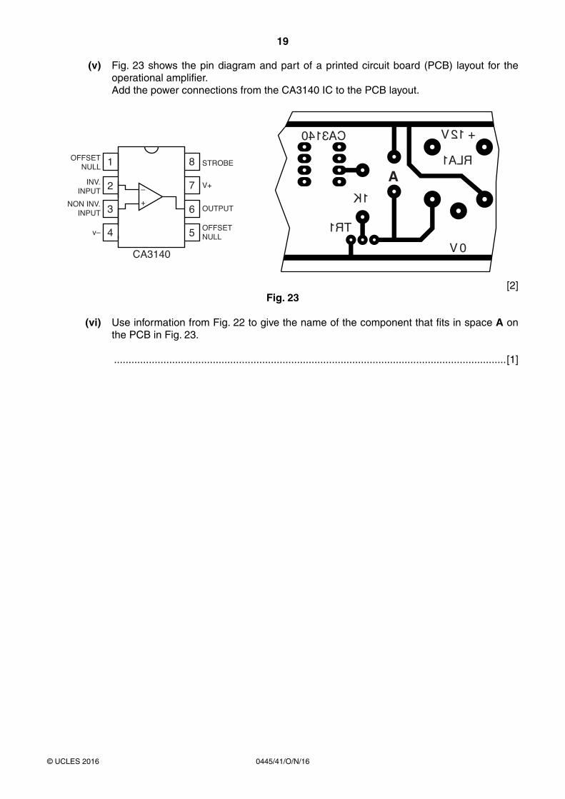
(v) Fig. 23 shows the pin diagram and part of a printed circuit board (PCB) layout for the operational amplifier.
Add the power connections from the CA3140 IC to the PCB layout.
1OFFSETNULL STROBE
V+
OUTPUT
CA3140
–
+
OFFSETNULL
INV.INPUT
NON INV.INPUT
v–
2
3
4 5
6
7
8
TR1
0 V
+ 12 V
RLA1A
1K
CA3140
[2]Fig. 23
(vi) Use information from Fig. 22 to give the name of the component that fits in space A on the PCB in Fig. 23.
.......................................................................................................................................[1]

20
0445/41/O/N/16© UCLES 2016
BLANK PAGE
Permission to reproduce items where third-party owned material protected by copyright is included has been sought and cleared where possible. Every reasonable effort has been made by the publisher (UCLES) to trace copyright holders, but if any items requiring clearance have unwittingly been included, the publisher will be pleased to make amends at the earliest possible opportunity.
To avoid the issue of disclosure of answer-related information to candidates, all copyright acknowledgements are reproduced online in the Cambridge International Examinations Copyright Acknowledgements Booklet. This is produced for each series of examinations and is freely available to download at www.cie.org.uk after the live examination series.
Cambridge International Examinations is part of the Cambridge Assessment Group. Cambridge Assessment is the brand name of University of Cambridge Local Examinations Syndicate (UCLES), which is itself a department of the University of Cambridge.