Camara de Espuma Contra Incendio
4
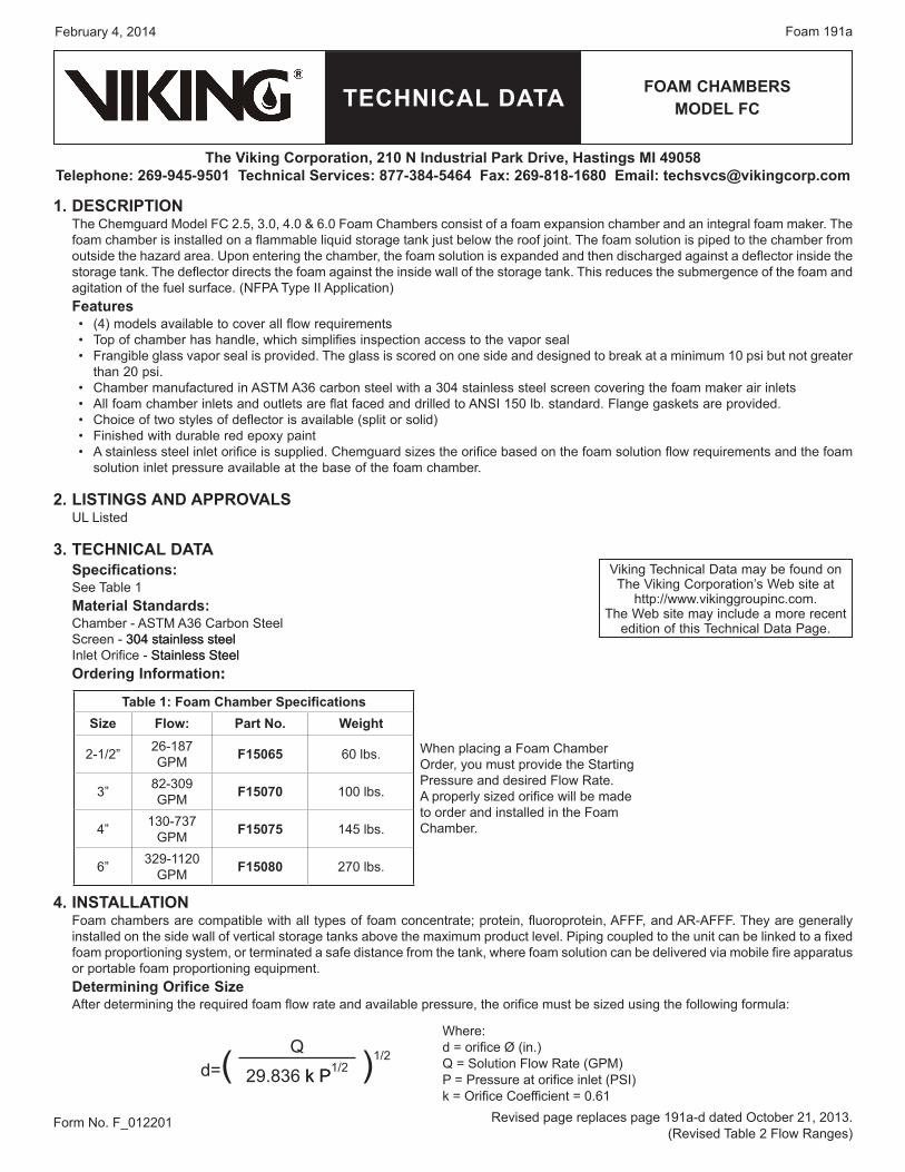
TECHNICAL DATA February 4, 2014 Foam 191a FOAM CHAMBERS MODEL FC The Viking Corporation, 210 N Industrial Park Drive, Hastings MI 49058 Telephone: 269-945-9501 Technical Services: 877-384-5464 Fax: 269-818-1680 Email: [email protected] 1. DESCRIPTION The Chemguard Model FC 2.5, 3.0, 4.0 & 6.0 Foam Chambers consist of a foam expansion chamber and an integral foam maker. The foam chamber is installed on a flammable liquid storage tank just below the roof joint. The foam solution is piped to the chamber from outside the hazard area. Upon entering the chamber, the foam solution is expanded and then discharged against a deflector inside the storage tank. The deflector directs the foam against the inside wall of the storage tank. This reduces the submergence of the foam and agitation of the fuel surface. (NFPA Type II Application) Features (4) models available to cover all flow requirements Top of chamber has handle, which simplifies inspection access to the vapor seal Frangible glass vapor seal is provided. The glass is scored on one side and designed to break at a minimum 10 psi but not greater than 20 psi. Chamber manufactured in ASTM A36 carbon steel with a 304 stainless steel screen covering the foam maker air inlets All foam chamber inlets and outlets are flat faced and drilled to ANSI 150 lb. standard. Flange gaskets are provided. Choice of two styles of deflector is available (split or solid) Finished with durable red epoxy paint A stainless steel inlet orifice is supplied. Chemguard sizes the orifice based on the foam solution flow requirements and the foam solution inlet pressure available at the base of the foam chamber. 2. LISTINGS AND APPROVALS UL Listed 3. TECHNICAL DATA Specifications: See Table 1 Material Standards: Chamber - ASTM A36 Carbon Steel Screen - 304 stainless steel 304 stainless steel Inlet Orifice - Stainless Steel Stainless Steel Ordering Information: 4. INSTALLATION Foam chambers are compatible with all types of foam concentrate; protein, fluoroprotein, AFFF, and AR-AFFF. They are generally installed on the side wall of vertical storage tanks above the maximum product level. Piping coupled to the unit can be linked to a fixed foam proportioning system, or terminated a safe distance from the tank, where foam solution can be delivered via mobile fire apparatus or portable foam proportioning equipment. Determining Orifice Size After determining the required foam flow rate and available pressure, the orifice must be sized using the following formula: • • • • • • • • Form No. F_012201 Viking Technical Data may be found on The Viking Corporation’s Web site at http://www.vikinggroupinc.com. The Web site may include a more recent edition of this Technical Data Page. Where: d = orifice Ø (in.) Q = Solution Flow Rate (GPM) P = Pressure at orifice inlet (PSI) k = Orifice Coefficient = 0.61 d=( Q ) 1/2 29.836 k P k P 1/2 Table 1: Foam Chamber Specifications When placing a Foam Chamber Order, you must provide the Starting Pressure and desired Flow Rate. A properly sized orifice will be made to order and installed in the Foam Chamber. Size Flow: Part No. Weight 2-1/2” 26-187 GPM F15065 60 lbs. 3” 82-309 GPM F15070 100 lbs. 4” 130-737 GPM F15075 145 lbs. 6” 329-1120 GPM F15080 270 lbs. Revised page replaces page 191a-d dated October 21, 2013. (Revised Table 2 Flow Ranges)
-
Upload
tomas-gaviria-martinez -
Category
Documents
-
view
75 -
download
4
Transcript of Camara de Espuma Contra Incendio
TECHNICAL DATA
February 4, 2014 Foam 191a
FoAm CHAmbErsmoDEL FC
The Viking Corporation, 210 N Industrial Park Drive, Hastings mI 49058Telephone: 269-945-9501 Technical services: 877-384-5464 Fax: 269-818-1680 Email: [email protected]
1. DEsCrIPTIoNThe Chemguard Model FC 2.5, 3.0, 4.0 & 6.0 Foam Chambers consist of a foam expansion chamber and an integral foam maker. The foam chamber is installed on a flammable liquid storage tank just below the roof joint. The foam solution is piped to the chamber from outside the hazard area. Upon entering the chamber, the foam solution is expanded and then discharged against a deflector inside the storage tank. The deflector directs the foam against the inside wall of the storage tank. This reduces the submergence of the foam and agitation of the fuel surface. (NFPA Type II Application)Features
(4) models available to cover all flow requirementsTop of chamber has handle, which simplifies inspection access to the vapor sealFrangible glass vapor seal is provided. The glass is scored on one side and designed to break at a minimum 10 psi but not greater than 20 psi.Chamber manufactured in ASTM A36 carbon steel with a 304 stainless steel screen covering the foam maker air inletsAll foam chamber inlets and outlets are flat faced and drilled to ANSI 150 lb. standard. Flange gaskets are provided.Choice of two styles of deflector is available (split or solid)Finished with durable red epoxy paintA stainless steel inlet orifice is supplied. Chemguard sizes the orifice based on the foam solution flow requirements and the foam solution inlet pressure available at the base of the foam chamber.
2. LIsTINGs AND APProVALsUL Listed
3. TECHNICAL DATAspecifications:See Table 1material standards:Chamber - ASTM A36 Carbon SteelScreen - 304 stainless steel304 stainless steelInlet Orifice - Stainless SteelStainless Steelordering Information::
4. INsTALLATIoNFoam chambers are compatible with all types of foam concentrate; protein, fluoroprotein, AFFF, and AR-AFFF. They are generally installed on the side wall of vertical storage tanks above the maximum product level. Piping coupled to the unit can be linked to a fixed foam proportioning system, or terminated a safe distance from the tank, where foam solution can be delivered via mobile fire apparatus or portable foam proportioning equipment.Determining orifice sizeAfter determining the required foam flow rate and available pressure, the orifice must be sized using the following formula:
•••
•••••
Form No. F_012201
Viking Technical Data may be found on The Viking Corporation’s Web site at
http://www.vikinggroupinc.com.The Web site may include a more recent
edition of this Technical Data Page.
Where: d = orifice Ø (in.)Q = Solution Flow Rate (GPM)P = Pressure at orifice inlet (PSI)k = Orifice Coefficient = 0.61
d=( Q )1/2
29.836 k Pk P1/2
Table 1: Foam Chamber specifications
When placing a Foam Chamber Order, you must provide the Starting Pressure and desired Flow Rate.A properly sized orifice will be made to order and installed in the Foam Chamber.
size Flow: Part No. Weight
2-1/2” 26-187 GPM F15065 60 lbs.
3” 82-309 GPM F15070 100 lbs.
4” 130-737 GPM F15075 145 lbs.
6” 329-1120 GPM F15080 270 lbs.
Revised page replaces page 191a-d dated October 21, 2013.(Revised Table 2 Flow Ranges)

TECHNICAL DATA
February 4, 2014Foam 191b
FoAm CHAmbErsmoDEL FC
The Viking Corporation, 210 N Industrial Park Drive, Hastings mI 49058Telephone: 269-945-9501 Technical services: 877-384-5464 Fax: 269-818-1680 Email: [email protected]
5. oPErATIoNThe Model FC Foam Chambers produce foam by introducing air into the foam solution stream. Foam solution can be delivered to the foam chamber in a variety of ways as previously noted. Air is drawn into the foam maker through a series of annular holes located around the integral foam maker. To prevent obstruction, the air inlet holes are protected by a stainless steel screen selected with a perforation size designed to exclude most known nesting birds and insects. The open area of the screen is designed to be not less than the total area of the foam maker air inlet holes.
6. INsPECTIoNs, TEsTs AND mAINTENANCENoTICE: The owner is responsible for maintaining the fire protection system and devices in proper operating condition. For minimum maintenance and inspection requirements, refer to recognized standards such as those produced by NFPA, LPC, and VdS which describe care and maintenance of sprinkler systems. In addition, the “Authority Having Jurisdiction” may have additional maintenance, testing and inspection requirements which must be followed.WArNING: Any system maintenance or testing which involves placing a control valve or detection system out of service may elimi-nate the Fire Protection of that system. Prior to proceeding, notify all Authorities Having Jurisdiction. Consideration should be given to employment of a Fire Patrol in the affected area.
7. AVAILAbILITyViking Foam Products are available through a network of domestic and international distributors. See the Viking web site for closest distributor or contact The Viking Corporation.
8. GuArANTEEFor details of warranty, refer to Viking’s current list price schedule or contact Viking directly.
Table 2: Accessoriessize Flow: Part No. Description Weight
2-1/2” 26-187 GPM
F15066 Solid Deflector 5 lbs.F15067 Split Deflector 5 lbs.F15068 Mounting Pad 15 lbs.F15069 Spare Vapor Seal Assembly 1 lbs.
3” 82-309 GPM
F15071 Solid Deflector 10 lbs.F15072 Split Deflector 10 lbs.F15073 Mounting Pad 20 lbs.F15074 Spare Vapor Seal Assembly 1 lbs.
4” 130-737 GPM
F15076 Solid Deflector 20 lbs.F15077 Split Deflector 20 lbs.F15078 Mounting Pad 35 lbs.F15079 Spare Vapor Seal Assembly 1 lbs.
6” 329-1120 GPM
F15081 Solid Deflector 30 lbs.F15082 Split Deflector 30 lbs.F15083 Mounting Pad 50 lbs.F15084 Spare Vapor Seal Assembly 2 lbs.

TECHNICAL DATA
February 4, 2014 Foam 191c
FoAm CHAmbErsmoDEL FC
The Viking Corporation, 210 N Industrial Park Drive, Hastings mI 49058Telephone: 269-945-9501 Technical services: 877-384-5464 Fax: 269-818-1680 Email: [email protected]
B
A
C
D
E
F
GH
I
SIDE VIEW
P Q
TOP VIEW
INLET FLANGE (E DETAIL)
ØK
ØL
ØJ
FC2.5, 3
OUTLET FLANGE (I DETAIL)
ØP
ØO
ØN
FC2.5, 3, 4
FC4, 6
ØL
ØK
ØJ
ØN
FC6
ØP
ØO
ØM
ØM
ØQ
ØQ
Figure 1 - Dimensions
FC2.5 FC 3 FC 4 FC 6A 26-13/16 32-1/16 35-13/16 42-7/8
b 15-1/4 19-9/16 20-13/16 25-7/16
C 15-5/8 12-3/4 14-3/4 18
D 7 9 10 12
E 2-1/2 3 4 6
F 3-1/4 4-1/4 5-3/8 6-3/8
G 6-1/2 8-1/2 10-1/2 12-1/2
H 8 9-1/2 11 12
I 4 6 8 10
J 1 2 2-1/2 3-1/2
K 5-1/2 6" 7-1/2 9-1/2
L 7 7-1/2 9 11
m 3/4 3/4 7/8 7/8
N 4-9/16 6-3/4 8-3/4 10-7/8
o 7-1/2 9-1/2 11-3/4 14-1/4
P 9 11 13-1/2 16
Q 3/4 7/8 7/8 1
r 8 12 16 20s 12 18 24 30
TECHNICAL DATA
February 4, 2014Foam 191d
FoAm CHAmbErsmoDEL FC
The Viking Corporation, 210 N Industrial Park Drive, Hastings mI 49058Telephone: 269-945-9501 Technical services: 877-384-5464 Fax: 269-818-1680 Email: [email protected]
50 60 70 80 90 100
110
120
130
140
150
160
170
40
50
60
70
80
90
100PSI
(2.76)
(3.45)
(4.14)
(4.83)
(5.52)
(6.21)
(6.89)(BAR)
GPM
(189
.3)
(227
.1)
(265
.0)
(302
.8)
(340
.7)
(378
.5)
(416
.4)
(454
.2)
(492
.1)
(530
.0)
(567
.8)
(605
.7)
(643
.5)
(LPM
)
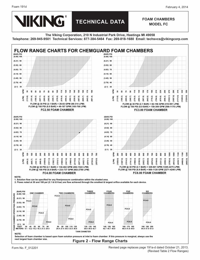
FLOW @ 30 PSI (2.1 BAR) = 26-83 GPM (98-314 LPM)FLOW @ 100 PSI (6.9 BAR) = 49-187 GPM (185-708 LPM)
FC2.50 FOAM CHAMBER
30 50 70 90 110
130
150
170
190
210
230
250
270
40
50
60
70
80
90
100PSI
(2.76)
(3.45)
(4.14)
(4.83)
(5.52)
(6.21)
(6.89)(BAR)
GPM
(113
.6)
(189
.3)
(265
.0)
(340
.7)
(378
.5)
(492
.1)
(567
.8)
(643
.5)
(719
.2)
(794
.9)
(870
.6)
(946
.3)
(102
2.1)
(LPM
)
FLOW @ 30 PSI (2.1 BAR) = 82-156 GPM (310-591 LPM)FLOW @ 100 PSI (6.9 BAR) = 158-309 GPM (598-1170 LPM)
FC3.00 FOAM CHAMBER
160
200
240
280
320
360
400
440
480
520
560
600
640
40
50
60
70
80
90
100PSI
(2.76)
(3.45)
(4.14)
(4.83)
(5.52)
(6.21)
(6.89)(BAR)
GPM
(605
.7)
(757
.1)
(908
.5)
(105
9.9)
(121
1.3)
(136
2.7)
(151
4.1)
(166
5.6)
(181
7.0)
(196
8.4)
(211
9.8)
(227
1.2)
(242
2.7)
(LPM
)
FLOW @ 30 PSI (2.1 BAR) = 130-402 GPM (492-1522 LPM)FLOW @ 100 PSI (6.9 BAR) = 233-737 GPM (882-2790 LPM)
FC4.00 FOAM CHAMBER
280
340
400
460
520
580
640
700
760
820
880
40
50
60
70
80
90
100PSI
(2.76)
(3.45)
(4.14)
(4.83)
(5.52)
(6.21)
(6.89)(BAR)
GPM
(105
9.9)
(128
7.0)
(151
4.2)
(174
1.3)
(196
8.4)
(219
5.5)
(242
2.7)
(264
9.8)
(287
6.9)
(310
4.0)
(333
1.2)
(LPM
)
FLOW @ 30 PSI (2.1 BAR) = 329-601 GPM (1245-2275 LPM)FLOW @ 100 PSI (6.9 BAR) = 600-1120 GPM (2271-4240 LPM)
FC6.00 FOAM CHAMBER
FLOW RANGE CHARTS FOR CHEMGUARD FOAM CHAMBERS
NOTE:1. Solution flow can be specified for any flow/pressure combination within the shaded area.2. Flows noted at 30 and 100 psi (2.1 & 6.9 bar) are flow achieved through the smallest & largest orifice available for each device.
40
50
60
70
80
90
100PSI
(2.76)
(3.45)
(4.14)
(4.83)
(5.52)
(6.21)
(6.89)(BAR)
30 40 50 60 70 80FEET9.1 12.2 15.2 18.3 21.3 24.4METERS
ONE CHAMBER
80 90 100 110 12024.4 27.4 30.5 33.5 36.6
TWO CHAMBERS
120 130 14036.6 39.6 42.7
CHAMBERSTHREE
140 150 16042.7 45.7 48.8
CHAMBERSFOUR
160 170 18048.8 51.8 54.9
CHAMBERSFIVE
180 190 20054.9 57.9 61.0
CHAMBERSSIX
NOTE:Selection of foam chamber is based upon foam solution pressure at inlet to foam chamber. If this pressure is marginal, always use thenext largest foam chamber size.
FOA
M C
HA
MB
ER O
PER
ATI
NG
PR
ESSU
RE
TANK DIAMETER
FC2.5
FC3.0
FC4.0
FC6.0
FC3.0
FC4.0
FC6.0
FC4.0
FC6.0
FC4.0
FC6.0
FC4.0
FC6.0
FC4.0
FC6.0
180
(681
.4)
680
(257
4.1)
30 40
(113
.6)
(151
.4)
30(2.1)
290
310
330
350
(109
7.8)
(117
3.5)
(124
9.2)
(132
4.9)
30(2.1)
120
(454
.2)
720
(272
5.5)
760
(287
6.9)
30(2.1) 30(2.1)
940
1000
1060
1120
1180
1240
(355
8.3)
(378
5.4)
(401
2.5)
(423
9.7)
(446
6.8)
(469
3.9)
30(2.1)
Figure 2 - Flow range ChartsForm No. F_012201 Revised page replaces page 191a-d dated October 21, 2013.
(Revised Table 2 Flow Ranges)