
CAM Tutorial CREO PARAMETRIC 1.0 week 1 Part 1 PART …polynet.dk/cad/exercises/UGE_1.pdf · CAM...
23
CAM Tutorial CREO PARAMETRIC 1.0 week 1 Part 1 Revised by Tomas Benzon DTU MEK March 2012 on basis of original COACH material Page 1 PART 1: BASIC MACHINING CREATING A MANUFACTURING MODEL In this Lesson you will create a Manufacturing Model by assembling the Design Model. The Design Model represents the finished part (after all of the machining takes place). You are actually going to start with a forging of this part and remove only a small amount of material in some areas. In this case, you are not going to assemble the forging (as a Workpiece). In later Lessons, you will learn how to utilize both the design part and the forging together. 1. Create a Manufacturing Model. ● Choose Home from the Menu bar ● Choose New Before starting this tutorial: Ensure that you have downloaded all CAM files from the write-protected drive (P:\Courses\41617-CAM) and placed them on your own drive (M:\) Set the Working Directory to the directory on your own drive where you placed the CAM files. Notice NC Assembly from the Subtype list is the default choice. Give it a name... Typically, let this be selected, (it controls whether you work in mm or in inches). When you initially open Creo on a new system, please make certain that it opens in mm. This should be checked for each file type. To verify which units the file is set up to, you can open top menu File / Prepare / Model Properties under the Materials paragraph. The Model Properties dialoque allows you to change units by choosing the change button to the right.
Transcript of CAM Tutorial CREO PARAMETRIC 1.0 week 1 Part 1 PART …polynet.dk/cad/exercises/UGE_1.pdf · CAM...

CAM Tutorial CREO PARAMETRIC 1.0 week 1 Part 1
Revised by Tomas Benzon DTU MEK March 2012 on basis of original COACH material Page 1
PART 1: BASIC MACHINING
CREATING A MANUFACTURING MODEL
In this Lesson you will create a Manufacturing Model by assembling the Design Model. TheDesign Model represents the finished part (after all of the machining takes place). You areactually going to start with a forging of this part and remove only a small amount of material insome areas. In this case, you are not going to assemble the forging (as a Workpiece). In laterLessons, you will learn how to utilize both the design part and the forging together.
1. Create a Manufacturing Model. ● Choose Home from the Menu bar ● Choose New
Before starting this tutorial:
Ensure that you have downloaded all CAM files from the write-protected drive (P:\Courses\41617-CAM) and placed them on your own drive (M:\)Set the Working Directory to the directory on your own drive where you placed the CAM files.
Notice NC Assembly from the Subtype list is the default choice.
Give it a name...
Typically, let this be selected, (it controls whether you work in mm or in inches). When you initially open Creo on a new system, please make certain that it opens in mm. This should be checked for each file type. To verify which units the file is set up to, you can open top menu File / Prepare / Model Properties under the Materials paragraph. The Model Properties dialoque allows you to change units by choosing the change button to the right.

CAM Tutorial CREO PARAMETRIC 1.0 week 1 Part 1
Revised by Tomas Benzon DTU MEK March 2012 on basis of original COACH material Page 2
● Choose Manufacturing from the Type list ●Type your initials_basic1 and hit ENTER or choose OK ● If you are able to choose units in this dialogue choose mmns
2. Assemble the Design Model. (Open the design model when you reside in the Manufacturing module) ● Set the graphic display to Shaded ● Click the Reference Model icon (not the text below with the arrow) ● In the dialoque box choose Profile1.prt and hit ENTER
Begin the NC Sequence by defining the minimum Operation data of a WorkCell Type.
1. Start the Sequence
● Click the Work Center icon on the top ribbon menu. The Milling Work Center dialogue will appear
● To constrain (place) the model press the Automatic button and choose default far down - This will position the model in the same 3D space as when constructed... ● The system may ask you to enter a Density value, just accept the suggested one, using ● Accept position by clicking
The Profile1.prt will appear on the screen - probably in a temporary state indicated by the dark purple color . If the model displays in white color (= automatic placement), you should skip the actions in the red frame under-neath. If you dont see anything on the screen, press CTRL+ D

CAM Tutorial CREO PARAMETRIC 1.0 week 1 Part 1
Revised by Tomas Benzon DTU MEK March 2012 on basis of original COACH material Page 3
The Milling Work Center displays...
Define An Operation ● On the top ribbon, choose the Operation icon ● A Machine Coordinate system (MCS) has to be defined. The system wants you to either create one or to point on an existing coordinate system. Here, one comes with the part:
OPERATION SETUP
The Work Center has now been defined. Now it is time to create an Operation. You need to do this before you can start defining NC sequences. Think of 1 operation = 1 clamping in the vice. An operation can contain one or several NC sequences.
You are now going to define the Machine Coordinate System (MCS). Whether you Select orCreate the Machine Zero coordi-nate system, you must always make sure that the Z Axis is pointing "up" towards the spindle on the NC Machine, and that the X Axis is pointing along thedefault tool motion. Remember, the tool axis is also going to be parallel to the Z Axis.
2. Define the Cell Type ● Choose Mill from the Machine Type option menu - Default choice... ● Choose 3 Axis from the Number of Axes option menu - Default choice... ● Choose OK - Yes, you didn’t change anything in this box, but this entry can’t be skipped.- You will notice that “MILL 01” now appears on the model tree .

CAM Tutorial CREO PARAMETRIC 1.0 week 1 Part 1
Revised by Tomas Benzon DTU MEK March 2012 on basis of original COACH material Page 4
The Menu Manager will appear on the right side of the sreen. Note that the Sequence Setup menu displays, showing you the required items: - Here you will have to fill out 4 dialogue boxes.
● With the Mill pane active, choose the grey Milling zone (Arrow)
● Choose Pocketing (meaning ”Digging holes”)
● Choose Done - The system will display the first of the four, Tools Setup window as shown next page:
● Now the Operation has been partially defined. It appears on the Model tree, and the Menu Manager pops up, requiring you to define the remaining variables:
● Select CSO by clicking it in the display window (provided you have turned on Csys Display). Please click on the CSO label and not on the 3D cross itself.(Arrow in bottom of page 3)
● Click on the accept icon. The system has now created a new csys (NC_CS0) to act as the MCS. (Machine Coordinate System) ● A new pane Mill has now appeared on the top Ribbon. By clicking it, a range of Milling options appears.

CAM Tutorial CREO PARAMETRIC 1.0 week 1 Part 1
Revised by Tomas Benzon DTU MEK March 2012 on basis of original COACH material Page 5
When you choose Done, the system will begin to offer you the menus to specify the required information....which in this case will be Tool, Parameters, Retract Surf, and Surfaces. These kinds of menus are known as "Walk Through" menus. You can manually add or remove entries, but stick to these four right now...
For unknown reasons, the Tools setup may be defined in Inlbs even when the manufacturing file is set to mm...
- A flat ended 25 mm/100 mm tool has now been defined
2. Define the Tool ● Choose End Mill ( Arrow)... ● Type 25 for diameter and 100 for height ( Arrows)...
● Verify that the units are Millimeters ( Arrow)... ● Choose Apply, followed by OK (more Arrows)

CAM Tutorial CREO PARAMETRIC 1.0 week 1 Part 1
Revised by Tomas Benzon DTU MEK March 2012 on basis of original COACH material Page 6
SPECIFYING PARAMETERS
The system now displays the Edit Parameters of Sequence window containing the minimum set of the parameters that are appropriate for the type of NC Sequence you are using.(pale yellow)
You should come back and explore more by changing the parameter values after playing the path and then notice the difference each parameter causes.
Alternatively, you can use the DOWN arrow key on the keyboard instead of clicking in the field...
● Click with the mouse cursor in the field to the right of the text CUT_FEED ●Type 75 and hit ENTER
Now to the second entry on the four-point list: Specify all of the required parameters, marked yellow:
● Click with the mouse cursor in the field to the right of the text STEP_DEPTH ● Type 6 and hit ENTER ● Click with the mouse cursor in the field to the right of the text STEP_OVER ● Type 6 and hit ENTER ● Click with the mouse cursor in the field to the right of the text CUT_ANGLE ● Type 90 and hit ENTER ● Click with the mouse cursor in the field to the right of the text SCAN_TYPE ● Click on TYPE_2 and hit ENTER
● Click with the mouse cursor in the field to the right of the text CLEAR_DIST ● Type 2.5 ● Click with the mouse cursor in the field to the right of the text SPINDLE_SPEED and type 500 ● Choose the All button located at the upper left in the window to display all parameters ● Find the POCKET_EXTEND option ● Change TOOL_ON to TOOL_TO ● Choose OK to exit the parameter setup window - The box closes, and a small third dialogue box , Retract Setup, comes next... ● Choose Done

Revised by Tomas Benzon DTU MEK March 2012 on basis of original COACH material Page 7
CAM Tutorial CREO PARAMETRIC 1.0 week 1 Part 1
MACHINING SURFACES
The Retract Plane defines the height above the Workpiece where the tool safely can hover around when moving from one job to another without crashing into the Workpiece.
The retract Plane distance is now 25 mm
The third point on the list: The system now wants you to define a Retract Plane and select the surfaces to be machined.The Retract Setup dialog has opened by it self and the brown grid shows its current distance from plane to model (=0)
●In the (Z Depth) Value text field type 25 and hit ENTER ●Choose the OK action button: The box closes. Now the tool will idle in a comfortable 25 mm Z distance from the Workpiece...

Revised by Tomas Benzon DTU MEK March 2012 on basis of original COACH material Page 8
CAM Tutorial CREO PARAMETRIC 1.0 week 1 Part 1
First this...
Followed by this...
It may appear red on your screen...
And then this...
Finally the system prompts you to specify which surfaces to be machined. ● Choose Model from the SURF PICK menu: Here the system wants you to choose some surfaces on the model for the purpose of milling these. ●Choose Done ●Select the green colored face shown below
● In the Select box, Choose OK ● Choose Done/ReturnPlay the tool path ● Choose Play Path ● Choose Screen Play ● Choose Play Forward Button
In the Play Path dialogue under “ View” there are various display settings for the tool, shaded, wireframe etc.

Revised by Tomas Benzon DTU MEK March 2012 on basis of original COACH material Page 9
CAM Tutorial CREO PARAMETRIC 1.0 week 1 Part 1
You may notice a few things about this tool path. The cutter moved in straight lines, parallel to the Y-Axis because the CUT_ANGLE is 90 degrees. The tool followed along the sides of the pocket to avoid cutting through the part. The tool cut around the protrusion or "island". This type of movement is a result of using the TYPE_2 - SCAN_TYPE. The path also retracts to the Retract Plane each time it must move to a new area. Retracts are automatically created in Creo/NC.
Here is the tool is shown shaded, the tool tip and the tool kerf is visible.
● Choose Close4. Save this tool path in memory. ● Choose Done Sec: - This step is important - it saves the whole operation ● Choose Done / Return
1. Begin a new sequence. ●Choose Pocketing - like you did at the upper middle of page 4
Now you will create a second NC Sequence to finish machine the pocket in the other side of the part.
Screen play with Play Path : This is how your first sequence will look.

Revised by Tomas Benzon DTU MEK March 2012 on basis of original COACH material Page 10
CAM Tutorial CREO PARAMETRIC 1.0 week 1 Part 1
The Menu Manager appears, and it only promts you for information on Parameters and Surfaces. Please notice that it in this new sequence the system reuses data from your previous sequense.(same Tool, MCS, and Retract plane)
● Choose Done - The Parameter dialogue box appears - Here too you can reuse data:
● Choose Edit / Copy from Step: A small dialogue box, Select Step, opens
● Close the Parameters box with the OK in the bottom of the box
● Choose the top line: 1: Pocket Milling, Operation: OP010, and close with an OK Now all the tool parameter data from the previous sequense will be reused.

Revised by Tomas Benzon DTU MEK March 2012 on basis of original COACH material Page 11
CAM Tutorial CREO PARAMETRIC 1.0 week 1 Part 1
Now the Menu Manager will appear and promt you for which surfaces you want milled: ● In the Menu Manager, under SURF PICK / MODEL, click Done
●Select the green colored face below
● Choose OK ● Choose Done/Return4. Play the tool path. ● Choose Play Path ● Choose Screen Play ● Choose Close
5. Save this tool path in memory. ● Choose Done Seq6. Take one more step. Play the entire Operation to see both pockets machined: Please remember: It takes one or more Sequences to define an Operation. One Clamping in the vice equals one operation
● Choose - in the top ribbon - the Manufacturing pane ● Click on the Rapid Fedrat icon: The Menu Manager opens

Revised by Tomas Benzon DTU MEK March 2012 on basis of original COACH material Page 12
CAM Tutorial CREO PARAMETRIC 1.0 week 1 Part 1
● In the Menu Manager choose Operation / OP010 / Done: The Play Path interface appears. ● Choose Play, let it run and notice that both sequences run in one continous movement
ATTENTION
The final step of the above exercise (The play of the whole operation) must be REVIEWED and APPROVED by your INSTRUCTOR to make you eligible for a signature on your approval sheet confirming your successful completion of this tutorial.
Leave this file open and continue to the next exercise. Before asking for review and approval please have both the completed exercises opened.

CAM Tutorial CREO PARAMETRIC 1.0 week 1 Part 2
Revised by Tomas Benzon DTU MEK March 2012 on basis of original COACH material Page 13
PART 2: VOLUME MILLINGDEFINING A VOLUME
Create a mill volume to rough remove material from a block of graphite which is used to form the EDM electrode shown below.
● Click on the arrow under the Workpiece icon ● Choose Create Workpiece ● Type stock_vol1 as the workpiece part name and hit ENTER ● In the Menu Manager choose Protrusion / Done ● Select NC_ASM_TOP as the Sketch Plane. You can select it on the screen or in the model tree. As son as the Sketch plane is chosen, the Sketcher ribbon appears. ● You can ignore the References dialogue.
2. Create a workpiece. This simulates a raw piece of material being milled. It is color coded green by default.
1. Create a manufacturing model using the NC Assembly manufacturing type and assemble the Ref Model called volume1.prt into it, similarly to the previous lesson - Remember to check that you work in mm. Accept the (Default) positioning of the Ref Model.

CAM Tutorial CREO PARAMETRIC 1.0 week 1 Part 2
Revised by Tomas Benzon DTU MEK March 2012 on basis of original COACH material Page 14
Project tool
Use Chain
Sketch Plane can be chosen here or here
The Workpiece (stock) has been created and, as you can see, contains the entire part.
Click on the edge, approximately here,
and then approximately here,
● In the Menu Manager click Accept - If the four edges do not want to chain, click Next to make it happen. ● click yes to the Loop question
● click the OK accept-sign
● Enter 85 for the protrusion Depth value and accept
● Choose the Project tool... ●In the Missing References dialogue chose Yes

CAM Tutorial CREO PARAMETRIC 1.0 week 1 Part 2
Revised by Tomas Benzon DTU MEK March 2012 on basis of original COACH material Page 15
Workpiece has been created
From this surface is where the Mill Volume will rise.(It is the deepest Z level the tool reaches) The Mill Volume will extend upward to the surface which you will specify.
3. Create the mill volume. ● Choose the Create Mill Volume tool
● Choose the Extrude tool
● Choose Placement, followed by Define- The Sketch Dialog box appears
● Right-click here repeatedly to highlight this face and left-click it to choose it as the sketch plane

CAM Tutorial CREO PARAMETRIC 1.0 week 1 Part 2
Revised by Tomas Benzon DTU MEK March 2012 on basis of original COACH material Page 16
TRIMMING A VOLUME
Trim the volume to the part.1. Perform the trim operation.
● Choose the Trim tool
● In the Menu Manager click Accept ● click yes to the Loop question ● click the OK accept-sign
● click the OK accept-sign.
The system has now created a volume that is a large block....in the next Segment, you will seehow to exclude the volume containing your part from this block. You will have to trim the Milling volume with the Ref Model. This is preferably done right after the creation of the Milling Volume...
● Choose the Extrude to tool, and select the top surface of the Workpiece
● Choose Sketch to begin sketching ● You don’t need references for this sketch ● Choose the Use Project tool, like before ● Choose Chain type ● Repeat the edge selection procedure you used before, when you drew the sketch for the Workpiece. The chain may be easyer to create if you select the bottom edges of the part (Arrow)
● Select VOLUME1.PRT in the viewport or in the model tree●Click OK...

CAM Tutorial CREO PARAMETRIC 1.0 week 1 Part 2
Revised by Tomas Benzon DTU MEK March 2012 on basis of original COACH material Page 17
● The Trim feature now appears in the Model tree
The Mill Volume in purple (Defining the material that has to be milled away) displayed in wireframe and shaded,(seen from below, design model and workpiece hidden)
3. Define a Work center ● Click the Work Center icon on the top ribbon menu. The Milling Work Center dialogue will appear4. Define the cell type. ● Choose Mill from the Machine Type list - Default setting ● Choose 3 Axis from the Number of Axes list - Default setting ● Choose OK from the Machine Tool Setup window - Yes, nothing was actually changed...
5. Define an Operation Setup and define Milling type. ● On the top ribbon, choose the operation icon ● Select the Coordinate System called CS0 ● Choose OK ● Choose the Mill Pane on the top ribbon ● Click on the Roughing icon, ● and below that, Click on the Volume Rough icon - The Volume Milling ribbon appears:
The dialogue above is a replacement of the Menu Manager walk-through menus. It contains sev-eral variables, which all must be defined in order to run an NC sequence. The yellow color signals which entries are still missing.
6. Define the Tool : ● Choose the Tool icon .The familiar Tools setup appears: ● For Type, choose End Mill (preselected ...) ● For tool length, type 100 ● For tool diameter, type 25 ● Verify that Tool specifications are in mm, and not in inches ● To exit, choose Apply, followed by OK - The profile Milling top dialog replaces the No Tool with 01: T0001 for Tool name

Revised by Tomas Benzon DTU MEK March 2012 on basis of original COACH material Page 18
9. Define the Clearance : - For defining the retract plane ● Choose the Parameters tab: The system now asks for a reference level in order to define a Z level where the tool can hover freely around without hitting anything: choose the top surface of the work piece as shown:
● To the right of the Value field type 15. = The Z distance between the tool tip and the work piece...
●Click the green Accept icon to save the Volume Milling sequence. 10. Play the Tool Path :
8. Define the Parameters :
● Choose the Parameters tab, and a small - scale version of the Parameter list appears: You can enter the full - scale version by clicking the icon in the bottom, but this is not necessary now... Focus on the yellow fields at this moment:
● To the right of CUT_FEED type 75 ● To the right of STEP_OVER type 6 ● To the right of ROUGH_STOCK_ALLOW type 1 ...This is not a yellow entry ● To the right of MAX_STEP_DEPTH type 25 ● To the right of ROUGH_OPTION Click on ROUGH_&_CLEAN_UP ...This is not a yellow entry ● To the right of CLEAR_DIST type 2.5 ● To the right of SPINDLE_SPEED type 500
7. Define the References : - The system needs to know what to mill away...
● Choose the Reference tab and, to the right of Machining Reference choose Select Items:
● Select the Milling volume on the screen:

CAM Tutorial CREO PARAMETRIC 1.0 week 1 Part 2
Revised by Tomas Benzon DTU MEK March 2012 on basis of original COACH material Page 19
Click here
Play Path View
You might be able to see that this is not a desirable path. Material was left around the outside of the volume and the outside of the part was not machined because the tool could not fit between the side walls of the part and the volume....To get an acceptable path, the Milling volume needs to be larger.
11. Play the NC/CHECK display. ● Before proceding, make sure that you can view the NC/CHECK simulation: Choose - in the upper left corner of the screen: File / Options. The Creo Parametric Options dialogue opens. Choose Configuration Editor (bottom left). On the long Config.pro list, being alphabetical, find nccheck_type. If the nccheck_type entry does not show, enter the Show field in the top of the dialogue:
● Choose the All options. Now the list gets very long, and nccheck_type will show. in the Value column verify that the nccheck (not Vericut ) option is selected. Leave with OK. ● Choose NC Check as shown: ● In the Model Tree, find the Volume Milling listing, right-click it, and choose this time Material Removal Simulation (Arrow)
● In the Menu Manager, at the bottom,Choose Run.
● Choose the Play Forward button ● Choose Close
● Set Display style to Wireframe. ● In the Model Tree, find the Volume Milling listing, right-click it and choose Play Path (Arrow)
NC CHECK display view. Colors may be different on your screen.

CAM Tutorial CREO PARAMETRIC 1.0 week 1 Part 2
OFFSETTING SURFACES
Modify the volume to allow the tool to travel beyond the part.1. Return to the PLAY PATH menu. ●Choose Done / Return from the NC CHECK menu 2. Modify the Mill volume by offsetting the walls. ● In the Model tree, right click the Trimmed Mill Volume from the feature list and choose Redefine Mill Volume
● Choose the Offset tool
●Choose The four vertical walls, one by one, using the mouse and the CTRL button
You are now editing the trimmed Mill Volume
Redefine Mill Volume
The system probably automatically pre - selects all the surfaces. Now you must manually choose which surfaces to offset

CAM Tutorial CREO PARAMETRIC 1.0 week 1 Part 2
Revised by Tomas Benzon DTU MEK March 2012 on basis of original COACH material Page 21
●Choose Value ● Check that Expand Feature is the chosen option ● Type 25 as the Distance
3. Replay the tool path ● In the Model Tree, right-click the 1. Volume Milling [OP010] and Choose Play Path ● Choose Screen Play ● Choose Play Forward icon
● Click the green accept icon below the Offset tab
● Click the following green accept icon below the Mill Volume tab
One wall has been chosen Four walls have been chosen
Theapp
The four walls have now been offset 25 mm outwards

CAM Tutorial CREO PARAMETRIC 1.0 week 1 Part 2
Revised by Tomas Benzon DTU MEK March 2012 on basis of original COACH material Page 22
● Choose Close4. Play the NC/CHECK display. ● In the Model Tree, right-click the 1. Volume Milling [OP010] post and choose Material Removal Simulation - The Menu Manager appears ● In the Menu Manager choose Run
5. Change the STEP_DEPTH value to allow for a more contoured rough tooling path.
● On the Model Tree, Single - click on 1. Volume Milling [OP010] post, to turn it active:
● verify that the Manufacturing pane is the active one, and open the Step Parameters dialogue
Both views show that the tool now has access to the Workpiece on all four sides
x
CAM Tutorial CREO PARAMETRIC 1.0 week 1 Part 2
Revised by Tomas Benzon DTU MEK March 2012 on basis of original COACH material Page 23
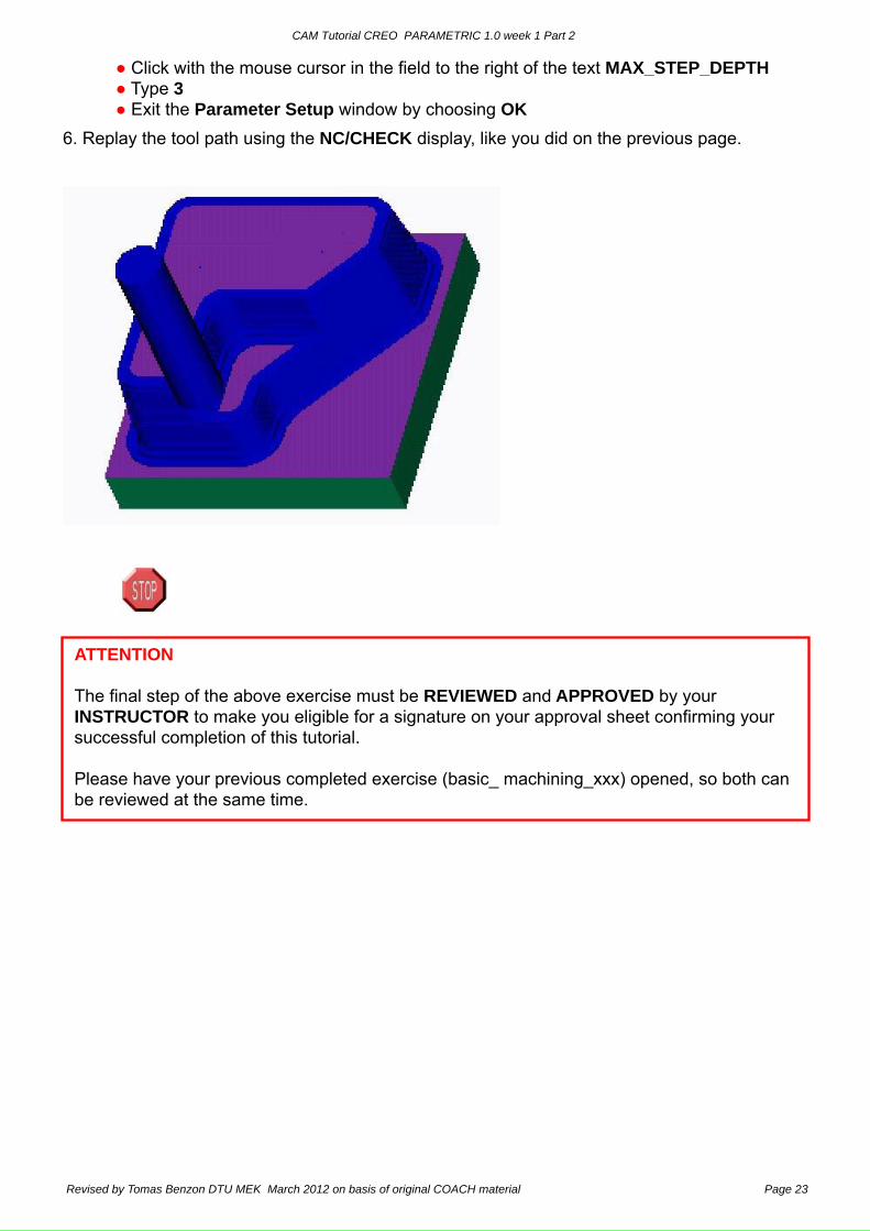
● Click with the mouse cursor in the field to the right of the text MAX_STEP_DEPTH ● Type 3 ● Exit the Parameter Setup window by choosing OK6. Replay the tool path using the NC/CHECK display, like you did on the previous page.
ATTENTION
The final step of the above exercise must be REVIEWED and APPROVED by your INSTRUCTOR to make you eligible for a signature on your approval sheet confirming your successful completion of this tutorial.
Please have your previous completed exercise (basic_ machining_xxx) opened, so both can be reviewed at the same time.


