
Cam Design and Manufac
141
ENGIN. LIBRARY IC-NRLF B 3 HE 353
-
Upload
joseph-h-finigan -
Category
Documents
-
view
220 -
download
0
Transcript of Cam Design and Manufac

8/6/2019 Cam Design and Manufac
http://slidepdf.com/reader/full/cam-design-and-manufac 1/140
ENGIN.LIBRARY
IC-NRLF
B 3 HE 353

8/6/2019 Cam Design and Manufac
http://slidepdf.com/reader/full/cam-design-and-manufac 2/140

8/6/2019 Cam Design and Manufac
http://slidepdf.com/reader/full/cam-design-and-manufac 3/140

8/6/2019 Cam Design and Manufac
http://slidepdf.com/reader/full/cam-design-and-manufac 4/140

8/6/2019 Cam Design and Manufac
http://slidepdf.com/reader/full/cam-design-and-manufac 5/140

8/6/2019 Cam Design and Manufac
http://slidepdf.com/reader/full/cam-design-and-manufac 6/140

8/6/2019 Cam Design and Manufac
http://slidepdf.com/reader/full/cam-design-and-manufac 7/140
CAM DESIGNAND MANUFACTURE

8/6/2019 Cam Design and Manufac
http://slidepdf.com/reader/full/cam-design-and-manufac 8/140

8/6/2019 Cam Design and Manufac
http://slidepdf.com/reader/full/cam-design-and-manufac 9/140
CAM DESIGNAND MANUFACTURE
BY
F. B. JACOBS
87 ILLUSTRATIONS
NEW YORK
D. VAN NOSTRAND COMPANYEIGHT WARREN STREET
1921

8/6/2019 Cam Design and Manufac
http://slidepdf.com/reader/full/cam-design-and-manufac 10/140
EngineeringLibrary
Copyright, 1921
By D. VAN NOSTRAND COMPANY
PRINTED IN THE UNITED STATES OF AMERICA

8/6/2019 Cam Design and Manufac
http://slidepdf.com/reader/full/cam-design-and-manufac 11/140
PREFACE
Cam movements are among the most useful that the
machine designer has at his command, for without them
many complicated motions could not be laid out and con-
structed. When cams are laid out by cut-and-try methods(which is often the case), they are noisy in operation,
create a vast amount of friction and are short-lived. On
the other hand, if the curves are properly laid out, giving
all possible time for the rises, the finished cams can be
run at high speeds with very little noise or friction.
Under these conditions, cams compare favorably in con-
struction cost and maintenance cost with more compli-cated mechanical movements used for the same purpose.
When it is considered that a practical knowledge of
cam design and manufacture is easily acquired, it mayseem strange that the majority of technical works on
machine design treat this subject lightly; or at least
from only a theoretical point of view. While it can not
be claimed that any one person knows the whole subject
thoroughly, it is certainly possible to explain some of the
methods that are in actual use for laying out and cutting
cams. The use of the various methods and appliances
that are described is not confined to any one locality, by
any means, as these methods and appliances have been
found in practically every manufacturing center of the
country.
In the description of the various methods, the writer
has avoided using complicated mathematical formulas as
it is well known that very few men actually engaged in
machine design and construction thoroughly understand
them. A working knowledge of geometry, algebra and

8/6/2019 Cam Design and Manufac
http://slidepdf.com/reader/full/cam-design-and-manufac 12/140

8/6/2019 Cam Design and Manufac
http://slidepdf.com/reader/full/cam-design-and-manufac 13/140
CONTENTS
CHAPTEE I
PAGE
MACHINE CAM DESIGN 1
CHAPTER II
GAS ENGINE CAM DESIGN 18
CHAPTER III
CAM FOLLOWERS 30
CHAPTER IV
MASTER CAMS 45
CHAPTER V
MACHINE WORK ON CAMS AND CAM CUTTERS 57
CHAPTER VI
CAM CUTTING 70
CHAPTER VII
CAM GRINDING . . 98
vn

8/6/2019 Cam Design and Manufac
http://slidepdf.com/reader/full/cam-design-and-manufac 14/140

8/6/2019 Cam Design and Manufac
http://slidepdf.com/reader/full/cam-design-and-manufac 15/140
CAM DESIGN AND MANUFACTURE
CHAPTER I
MACHINE CAM DESIGN
The majority of cam movements may be described as
devices for changing rotary motion into regular or inter-
mittent reciprocating motion. Other forms of cams,
are utilized for changing the direction of reciprocating
motions. The majority of cams used in machine con-
struction are of the first type, as seen on shoe and textile
machinery, printing presses, and other forms of auto-
matic machinery.
FIG. i
The two cams illustrated in Fig. 1 are called "opencams ' '
because the roll bears at only one point at a time.
"A" is a disk cam, the movement being developed on the
periphery. "B" is a drum cam, in which the movement
1

8/6/2019 Cam Design and Manufac
http://slidepdf.com/reader/full/cam-design-and-manufac 16/140
: DE&JG-N AND MANUFACTUEE
is developed on one side. These are sometimes called
barrel cams. An objection to open camsis
that a weight,or spring, has to be employed to keep the roll in position.
However, as cams of this type can often be cut without
a master they are frequently used for experimental pur-
FIG. 2.
poses. Again, they possessthe
advantageof
givingmore
abrupt rises than is possible with path cams, and for this
reason they are used on automatic screw machines, for
actuating gas engine valves, and for various other pur-
poses where rapid rises are desired.
The cams shown in Pig. 2 are called "path cams" be-
cause their rolls are confined to a path, or groove. They
aregenerally
seen in
placeswhere accurate movements
are required, and where it is not practicable to utilize a
weight, or spring, to keep the roll in contact. As these
cams are the hardest to lay out and cut, their use is gen-
erally confined to accurate machinery. Cams of this
type, however, possess one disadvantage; that is their
2

8/6/2019 Cam Design and Manufac
http://slidepdf.com/reader/full/cam-design-and-manufac 17/140
MACHINE CAM DESIGN
inability to take extremely rapid rises, the reasons for
which will be explained later on.
While both open and path cams can be of either type,
that is disk or drum, the disk type is the more popular
as it is easier to cut, runs with less friction, and has no
disadvantages worth mentioning. Drum cams create an
unnecessary amount of friction and wear on their rolls,
owing to the fact that the outer edge of the path has a
greater peripheral speed than the inner, due to the in-
crease in diameter.
FIG.
It can be said in favor of the drum cam that it is very
easily designed, as the development is laid out flat, and
in straight lines, instead of in converging lines and circles
as with disk cams. Again, it is often necessary to em-
ploy drum cams in cases where the movement runs par-
allel with the cam shaft.
In Fig. 3 is shown a form of cam called a wiping cam.
These are used in cases where a sudden drop is required.
3

8/6/2019 Cam Design and Manufac
http://slidepdf.com/reader/full/cam-design-and-manufac 18/140
CAM DESIGN AND MANUFACTURE
As the follower is a fixed piece in place of the usual roll,
cams of this
typeare short-lived : a
largeamount of fric-
tion being present, especially in cases where the operator
neglects to oil the movement frequently. Notwitstanding
this objection, this form of cam is frequently employed
as it gives a simple method of acquiring the desired
motion.
The cam illustrated in Fig. 4 is called an eccentric cam.
It
givesan
easymotion in cases where advances with
intermittent rests are desired. This type of cam is often
c
QFIG. 4
D
used foroperating
the valvegears
of the stern and side
wheel steamboats that are seen on the Mississippi River
and its tributaries.
Eccentric cams are also used in the construction of
accurate shoe machinery. When operated at moderate
speeds this type of cam works easily, is comparatively
4

8/6/2019 Cam Design and Manufac
http://slidepdf.com/reader/full/cam-design-and-manufac 19/140
MACHINE CAM DESIGN
long-lived, and calls for little attention, save for an occa-
sional adjustment of the plates that confine it. There
are many other forms and modifications of cams, includ-
. 5
ing plate cams, one of which is shown in Fig. 5, but the
cams above described are the types most frequently used.
The first step in laying out a cam is to consider the
motion required withthe intervals of action
and rest;it
being assumed that the type of cam whether open or
FIG. 6
path, disk or drum, has been decided upon. A chart, as
shown in Fig. 6, is now drawn. This shows by its ordi-
nates the rises and rests in their exact proportion as
5

8/6/2019 Cam Design and Manufac
http://slidepdf.com/reader/full/cam-design-and-manufac 20/140
CAM DESIGN AND MANUFACTUEE
they will appear in the finished cam. If the cam is to be
of the drum type the length of the chart should just equal
the circumference of the finished cam. If a disk cam is
to be used the length of the chart should equal approxi-
mately the smallest circumference of travel in the fin-
ished cam. This precaution is taken to avoid too abrupt
rises which would work hard, and in extreme cases lock.
FIG.
This is readily understood when we stop to consider
that the base and hypothenuse of the triangle, showing
the angle of motion, change as the circumference of the
cam is made greater or less, while the altitude, which
represents the stroke, is always fixed as it represents a
definite dimension. Thus, if Fig. 6 represents the cir-
cumference of a cam leader, from which a smaller cam is
to be cut, which is the generally accepted practice, it is
evident that the angle shown at "A" would be made
more abrupt as the circumference decreased. As it is an
angle of 45 at present, which is practically the limit for
fast and smooth running, it is evident that a sharper
6

8/6/2019 Cam Design and Manufac
http://slidepdf.com/reader/full/cam-design-and-manufac 21/140
MACHINE CAM DESIGN
angle would cause the cam to work very hard and under
some conditions to lockentirely.
Where several cams are to run on one shaft, or on
different shafts at the same speed, it is a good plan to
make a compound chart as illustrated in Fig. 7, taking
care that the lines representing the several circumfer-
ence are approximately the correct lengths. In a chart
of this kind, the lines representing the divisions of the
cam are diverted to
pass through corresponding pointsrepresenting equal degrees or divisions of a circle. By
referring to this chart the designer can see before him
all the motions for a machine in their correct relation to
each other. In many cases, this saves confusion in try-
ing to compare one cam motion with another, laid out on
a different chart. From the cam chart the leaders are
laid out, but beforetaking up
this
pointit
maybe well to
consider a few of the cam curves, which represent the
travel of the center of the cam roll, and a difficulty, often
met with, called"cutting back."
There are three varieties of cam curves in common use.
These are shown in Fig. 8. Illustration "A" is called
the uniform motion or regular rise and is used for con-
verting rotarymotion into
regular reciprocatingmotion.
This is a hard working movement as it starts and comes
to a rest with a decided shock, even when run at mod-
erate speeds. For this reason it should be avoided as
much as possible. As this motion is easily laid out,
either for a drum or disk cam, it is often used by inex-
perienced designers in cases where another motion would
serve the
purposeto better
advantage.In laying out this motion the base of the triangle
equals the division of the cam that is allowed for com-
pleting the stroke. The altitude equals the stroke of the
cam. The angle, which is not considered unless it is
steep enough to be detrimental to smooth running, is de-
7

8/6/2019 Cam Design and Manufac
http://slidepdf.com/reader/full/cam-design-and-manufac 22/140
CAM DESIGN AND MANUFACTUEE
termined by the altitude and time division of the cam
circle. It is necessary to draw curves at the start and
stop of this motion if the cam is to be of the path type.
c
FIG. 8
This is to avoid "cutting back," which will be explained
later.
In "B" is: illustrated a modified form of uniform
motion, the curves serving to reduce the shock of start-
ing and stopping. This motion can be used in cases
where it is necessary to have a uniform motion for the
greater part of the stroke, but where a little time can be
8

8/6/2019 Cam Design and Manufac
http://slidepdf.com/reader/full/cam-design-and-manufac 23/140
MACHINE CAM DESIGN
spared for getting under way and stopping. When pos-
sible,the radii of the curves that fill in the ends should
equal the diameter of the cam roll. Many designers
claim that this form of curve, which is an inclined plane
with the ends modified, is theoretically correct because
an inclined plane is one of the elementary mechanical
.powers put to actual use. Experience, however, has
proven that other forms of curves are more quiet in
operationand
longerlived. In cases where a uniform
motion is called for, this curve is an improvement over
the direct motion. This curve is drawn, as illustrated,
by bisecting the angles and filling in with curves whose
radii equal the diameter of the roll.
The crank motion, or harmonic curve, is shown at"C."
It is a well known fact that any machine part that is
actuatedby
a crank andconnecting
rod starts andstops
slowly, due to the angularity of the rod. The motion in
question, which is a modification of the above principle,
starts and stops without shock; the greater amount of
work being performed after the motion is well under
way. This motion can generally be used to advantage,
for in the majority of cases it is not necessary that the
partsactuated
bythe cam move with an absolute uni-
form motion.
This curve is laid out by drawing a circle, the diameter
of which is equal to the rise, and dividing it into any con-
venient number of equal parts. The line equaling the
motion of the cam is then divided into the same number
of equal parts. The curve passes through the intersec-
tions of the lines drawn from the motion line and the
circle.
Another motion, called the gravity curve, is sometimes
employed. It is developed in the same way as the har-
monic curve from an ellipse in place of the circle. The
major and minor axes have a relation of 11 to 8, the
9

8/6/2019 Cam Design and Manufac
http://slidepdf.com/reader/full/cam-design-and-manufac 24/140
CAM DESIGN AND MANUFACTURE
minor axis representing the stroke of the cam. In actual
practice, however,it has never been
definitely proven
FIG. 9
that the gravity curve works any easier, or is productive
of longer life, than the regular harmonic motion. For
this reason, together with the fact that it calls for more
10

8/6/2019 Cam Design and Manufac
http://slidepdf.com/reader/full/cam-design-and-manufac 25/140
MACHINE CAM DESIGN
attention in laying out, both on the drawing board and
on the camleader,
it is seldom used inpractice.
By referring to"A," Fig. 9, it is seen that the distance
between "EE" is greater than the width of the cam
path. In shop language, this is termed "cutting back"
and the principle is easily understood by glancing at
illustration "B," in which "G" represents the outline of
the milling center that has just completed the path"H."
Incutting
the
pathat "1" the cutter will cut
away partof the wall shown by the heavy line, thus making it im-
possible for the roll to fill the path completely at this
point.
This difficulty is overcome by drawing the circle "JJ"in illustration "C," with a radius equal to that of the
roll. The center of this milling cutter follows that part
of this circle "JJ" included between thepoints
of tan-
gency with the straight parts of its path. Here it is
seen that the roll completely fills the path at all points.
It is not necessary to lay out the circle "JJ" to develop
the point "L," as the cut back is automatically avoided
at this point, all the circles shown in "A" coming to the
point "K" just as they do at "L" in illustration "C"where the roll circles are drawn from
pointson the circle
"JJ" between its points of tangency with the straight
lines.
With open cams, cutting back does not have to be taken
into consideration, as it is only necessary for the roll to
have a bearing point on one side. This is the reason
why it is possible to obtain very abrupt rises with opencams.
Cutting back is always to be considered where very
sharp rises are required, and this factor often deter-
mines whether the cam shall be a path cam or an openone. This is explained in Fig. 10. Let it be assumed
that it is necessary to obtain the rise between the points
2 11

8/6/2019 Cam Design and Manufac
http://slidepdf.com/reader/full/cam-design-and-manufac 26/140
CAM DESIGN AND MANUFACTUEE
"A A" is the shortest possible time;which is determined
by the revolution time required for a cam to roll over a
given point. This may sound like a paradox, but a little
FIG. 10
study of Fig. 10 will impart the theory. Draw the line
of motion "BB." From points on this line the several
circles representing the roll are drawn. As they all
come together at the point "D," the center of the roll
may travel on the arc "EE" thus imparting the motion
"F F," in which the rise is accomplished in the time it
takes the cam to travel the distance represented by the
lines "GG." When we measure the distance between
the points "C" and "D" and compare it with the space
12

8/6/2019 Cam Design and Manufac
http://slidepdf.com/reader/full/cam-design-and-manufac 27/140
MACHINE CAM DESIGN
between the points "H" and "H," the width of the cam
path, we find that the cut back is very pronounced. Thus,as we desire to obtain the rise in the shortest possible
time, this cam would have
to be of the open type.
If this cam were to be of
the path type, it would be
necessary to develop the
line of motion on the two
arcs "JJ" to avoid cut-
ting back. In this case,
the rise would be accom-
plished in the time it takes
the cam to travel the dis-
tance represented by the
lines "KK," which is FIG. 11
greater than the distance
between the lines "GG," as the illustration shows.
Before proceeding any farther with the subject, it maybe of interest to consider several typical cam movements,
taking note of their outlines
as they will appear on the
finished cams.
Fig. 11 illustrates a regu-
lar rise and fall movement,
often called the ^heart-shaped
cam," wherein the rise is reg-
ular for a half-revolution,
followed by a drop wherein
the motion of the actuated
part is reversed. This motion
is used in place of a crank and connecting rod, in cases
where errors due to rod angularity would prove detri-
mental.
S+art
FIG. 12
13

8/6/2019 Cam Design and Manufac
http://slidepdf.com/reader/full/cam-design-and-manufac 28/140
CAM DESIGN AND MANUFACTURE
In Fig. 12 is shown a rise of 2" in
i rev.,followed
byadrop
of\"
in\
rev., next a rise of \" in-J rev., then
a drop of If" in f rev., which com-
pletes the circle.
Fig. 13 illustrates a rise of If" in
\ rev., a rest of \ rev., a drop of If"
in \ rev., and a rest of i rev. This
is an eccentric cam and can be usedfixed fol-
Start
FIG. 13
either with a
lower or a roll. It is some-
times called a four-throw
eccentric, because if placed
in a box that would con-
fine it on all sides it would
impart four movements.
It is symmetrical about
the vertical center line.
The movement shown in
Fig. 14 consists of a rest
of | rev., followed by four
FIG. 15
alternate drops and rises
of " in periods of-J
rev.
The motion shown in
Fig. 15 illustrates a rest
of iV rev., a rise of J" in iV
rev., a rest of-J rev., a drop
of J" in iV rev., a rest of-J
rev., a drop of f" in iV
rev., a rest of-J rev., and
a rise of f" in iV rev.
In Fig. 16 is shown a
drop of f" in iV rev., fol-
lowed by a rest of ^ rev.,
14

8/6/2019 Cam Design and Manufac
http://slidepdf.com/reader/full/cam-design-and-manufac 29/140
MACHINE CAM DESIGN
then a rise of f"in tV rev., \start
and a rest for the remain-
der of the circle. Cams of
this kind are sometimes
used for actuating feed
movements. Fig. 17 shows
the same movement re-
versed. As the sole ob-
ject is to move a lever a
given distance in a given
time, either cam will an-
swer the purpose.
Fig. 18 illustrates a wip-
ing cam having a sudden
dropof H" followed
bya rise of the same distance in f
rev. The remainder of the circle is a rest period. Wip-
FIG. 16
FIG. 17 FIG. 18
ing cams are generally"under-cut
"as the illustration
shows. This is to give the follower a free movement
without danger of cramping.
15

8/6/2019 Cam Design and Manufac
http://slidepdf.com/reader/full/cam-design-and-manufac 30/140
CAM DESIGN AND MANUFACTURE
A cam rocker, which is another form of wiping cam, is
shown in Fig. 19. These are used for various purposes,the one illustrated being of the type used for lifting the
FIG. 19
valves of the beam engines used on side-wheel steam
boats. These cams are generally laid out to impart a
r J
< Direction ofMotion
FIG. 20
uniform rise to the follower, which is a flat toe piece, as
the illustration shows. The method of generating this
curve is explained in Chapter Seven.
16

8/6/2019 Cam Design and Manufac
http://slidepdf.com/reader/full/cam-design-and-manufac 31/140
MACHINE CAM DESIGN
Fig. 20 illustrates a plate cam. These generally move
in a horizontal or vertical line, although they are some-
times used in connection with a sector, being actuated by
a rotary motion. The cam shown gives a rise of V dur-
ing a travel of 1", a rest of J", a drop of \" during a
travel of V and then a rest. The return stroke is the
reverse of this movement.
17

8/6/2019 Cam Design and Manufac
http://slidepdf.com/reader/full/cam-design-and-manufac 32/140
CHAPTER II
GAS ENGINE CAM DESIGN
In the design of cams for operating gas engine valves,
it is sometimes the practice to employ the cut-and-try
method, which consists of machining and filing an ex-
perimental cam until it imparts the desired motion to the
valve. More efficient results, however, can be obtained
by laying out the cam, as thereby the periods of rest
and motion can be exactly proportioned. This is quite
necessary as the cam shaft runs only half as fast as the
crank shaft, and this requires close adjustment of the
periods of rest and action.
In theory, the exhaust valve should open quickly at the
completion of the impulse stroke, and close quickly at the
completion of the exhaust stroke. In actual practice,
however, this is impossible, as the comparative slow
speed of the half-time shaft would necessitate steep cam
rises, which would cause the cams to be noisy and short-
lived.
The difficulty is overcome by starting to open the ex-
haust valve before the completion of the impulse stroke,
and closing it on, or after, the completion of the exhaust
stroke. On this same principle allowances are also made
for the opening and closing of the inlet valve. The de-
sign of cams for the comparatively slow running, hori-
zontal type of gas engine calls for practically the same
methods used in designing any machine cam. With auto-
mobile, airplane and some types of marine engines, how-
ever, a different method is employed, and for this reason
the two methods will be described separately.
18

8/6/2019 Cam Design and Manufac
http://slidepdf.com/reader/full/cam-design-and-manufac 33/140
GAS ENGINE CAM DESIGN
In Fig. 21 is illus-
trated the first step
that should be taken
in laying out the cams
for a horizontal gas
engine. This is an
angularity chart, giv-
ing the positions of
the piston and crank
pin for sixteen equal
parts of one half-
revolution. It is, of
course, necessary that
the stroke and length
of the connecting rod
shall have been deter-
mined, as changes in
either of these fac-
tors would give dif-
ferent movements,due to a change in
rod angularity. It is
not necessary to mark
off any more divi-
sions than a few at
the beginning and
completion of the
stroke, although in
this case they are all
shown with the idea
of making the prin-
ciple more easily un-
derstood. It is read-
ily seen that from a
chart of this kind the
12- inch Stroke
20-inchConnecting Rod
FIG. 21
19

8/6/2019 Cam Design and Manufac
http://slidepdf.com/reader/full/cam-design-and-manufac 34/140
CAM DESIGN AND MANUFACTTJEE
A
7
77
\
\
_
\
\
20

8/6/2019 Cam Design and Manufac
http://slidepdf.com/reader/full/cam-design-and-manufac 35/140
GAS ENGINE CAM DESIGN
amount of time that can be spared for the opening and
closingof the valves is
easilydetermined. Sixteen divi-
sions are not arbitary, by any means. Some designers
prefer to use some factor of 360, thereby representing
degrees instead of mere divisions.
A cam chart as shown in Fig. 22 is next drawn. On
this chart the line "A" gives the motion of the piston for
two strokes, the line "B" the motion of the exhaust
valve,and the line "C" the motion of the inlet valve. In
connection with the inlet valve, however, the line "A"
represents the intake and compression cycles, while with
respect to the exhaust valve it represents the impulse
and exhaust strokes. This eliminates the drawing of the
long chart which would otherwise be necessary, as the
cam shaft, generally spoken of as the"half-time
"shaft,
makes but one revolution to two of the crank shaft.
As the cam chart is to be used in connection with the
angularity chart, it is necessary that the number of divi-
sions for each stroke correspond. In determining the
amount of time to be allowed for the periods of rest and
motion, no two designers hold the same opinion. This
explains why we see some gas engines with easy riding,
quiet running cams,while others have
sharp rising, noisyones. The proportions here described, however, have
given excellent results in actual use.
By referring to Fig. 21 it is seen that the piston moves
slower at the outer end of the stroke than it does at the
start. For this reason, more time can be allowed for the
opening of the exhaust valve than can be spared for
closing it. In Fig. 22 the exhaust valve starts to rise at
division 13 of the out stroke and is wide open on division
14 of the back stroke, remaining open until division 3 of
the back stroke is reached. As the piston moves more
rapidly at the completion of the exhaust stroke than it
does at the completion of the impulse stroke, the cam
21
8/6/2019 Cam Design and Manufac
http://slidepdf.com/reader/full/cam-design-and-manufac 36/140
CAM DESIGN AND MANUFACTURE
must fall more rapidly than it rises. In Fig. 22 the ex-
haust valve is
fullyclosed when the
pistonis at the end
of the exhaust stroke. The inlet valve starts to open
while the piston is at the beginning of the intake stroke,
FIG. 23
and is wide open on division 5. It starts to close on
division 13, and is fully closed at the completion of the
intake stroke.
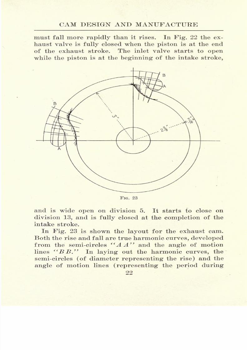
In Fig. 23 is shown the layout for the exhaust cam.
Both the rise and fall are true harmonic curves, developed
from the semi-circles "A A" and the angle of motion
lines "BB." In laying out the harmonic curves, the
semi-circles (of diameter representing the rise) and the
angle of motion lines (representing the period during
22
8/6/2019 Cam Design and Manufac
http://slidepdf.com/reader/full/cam-design-and-manufac 37/140
GAS ENGINE CAM DESIGN
which the rise occurs) are divided into the same number
of
equalparts. Straight lines are drawn from the divi-
sions of the semi-circles to their axes, and the curves
representing the travel of the center of the cam roll pass
through points where the concentric arcs drawn from
the axes and radial lines drawn from the angle of motion
line meet.
As before stated, the design of cams for the slow run-
ning, horizontal type of gas engine calls for practically
the same methods as those used in designing machine
cams. Designs for cams for automobile engines have,
however, been developed by experimenting with various
shaped cams, from which formulas were afterward stand-
ardized.
In determining the periods of rest and motion for
automobile engine cams, no two engineers agree. It is
common practice, however, to have the exhaust valve
start to open when the crank pin is approximately 25
from its lowest point on the impulse stroke, the valve not
fully closing until the crank pin has travelled 10 on the
intake stroke. This is shown in Fig. 21. The inlet valve
starts to open as soon as the exhaust valve is fully closed,
and closes at the completion of the intake stroke, or
sometimes a few degrees afterward. Anyone who has
had occasion to examine the valve motions of several
leading makes of automobile engines will admit that the
timing of the valves varies, sometimes to a considerable
extent.
In designing any automobile engine cam, the first step
is to decide upon the periods of rest and rise, as these
two factors determine the time that can be allowed for
rising, remaining open, and closing. As before stated,
it is common practice to open the exhaust valve 25 before
the completion of the impulse stroke, and to close it 10
after the completion of the exhaust stroke, or 10 on the
23

8/6/2019 Cam Design and Manufac
http://slidepdf.com/reader/full/cam-design-and-manufac 38/140
CAM DESIGN AND MANUFACTUBE
intake stroke, which is one and the same thing. By re-
ferring to Fig. 21 it is seen that the piston has very little
movement during the time in which the crank pin travels
over the degrees above mentioned;therefore very little,
if indeed any, power is wasted.
A B C^D E
FIG. 24
As an example, let it be assumed that the exhaust valve
is to open when the crank pin is within 25 of its lowest
point on the impulse stroke, and to close after the pin
has traveled 10 on the intake stroke, and that a valve
rise of 3*2" is necessary. In this case, the valve is closed
while the crank shaft travels over 170 of the intake
stroke, 180 of the compression stroke, and 155 of the
24

8/6/2019 Cam Design and Manufac
http://slidepdf.com/reader/full/cam-design-and-manufac 39/140
GAS ENGINE CAM DESIGN
impulse stroke, making 505 in all. As the half time
shaft travels
only
half as fast as the crank shaft, it is
evident that the cam should have a rest period of 252^.
The layout of this cam is illustrated in Fig. 24, the
lines "H H," defining the period of rest being spaced
252^ apart. The lines "JJ" are drawn at right angles
with the lines "HE" and therefore tangent to the circle
"K." The arc "L," which determines the rise of the
cam, is A" from the circle "K." The points where the
lines "MM" intersect the arc "L" determine the length
of time that the valve remains stationary while open,
which in this case is 27J. The same method is employed
in laying out the inlet valve cam, the only difference
being that the period of rest is longer, while the period
of action is shorter.
The cam above described is sometimes called a tan-
gential cam because its sides are tangent with its hub.
Although this type of cam is used extensively at the
present day, it is not modern by any means, as it was
used on the famous De Dion Bouton engines, over 20
years ago, in the days when automobiles were called
horseless carriages. By referring to the development of
this cam, it is seen that the rise is very easy; in fact, it
is not unlike the well known harmonic curve.
In laying out the development of this cam, the part of
the circle "K" that represents the angle of motion is
divided into six equal parts, marked "ABCDEF,"and radial lines from these divisions carried to the
periphery of the cam. (These lines point toward the
cam's center, which is necessary to obtain a true devel-
opment). Divisions the same distance apart are now
laid off in the lower diagram on the line "NN," or inner
line of cam face. The distance between the points "A,"
"B," "C," "D," "E," "F," is the same in both draw-
ings. A curve representing the line of cam face is drawn
25

8/6/2019 Cam Design and Manufac
http://slidepdf.com/reader/full/cam-design-and-manufac 40/140

8/6/2019 Cam Design and Manufac
http://slidepdf.com/reader/full/cam-design-and-manufac 41/140
GAS ENGINE CAM DESIGN
determined by the radius of the arc "C," which has its
center on the circumference of the main circle. The di-
mension "E" is the stroke of the cam, that is &".
FIG. 26
This is a poor design as the rise is not rapid enough.
Notwithstanding that the valve rises the required dis-
tance from its seat, it is not fully open long enough to
free the cylinder of the burned gas. Again, as it opens
slowly, owing to the fact that the arcs "B B" do not im-
part any noticeable lift to the valve when it starts to
open, the factor of "wire drawing" is present and will
cause excessive wear of both valve and seat. Further,
there is always some backlash between the push rod and
the valve stem, also between the cam roll and the stud,
especially in cases where the engine has been in use for
some time without due attention having been paid to
adjustments.
3 27

8/6/2019 Cam Design and Manufac
http://slidepdf.com/reader/full/cam-design-and-manufac 42/140
CAM DESIGN AND MANUFACTURE
The factor of backlash is overcome in the cam shown
in Fig. 26. Here the theoretical rest is shortened 40,
the arcs "A A" being drawn from points on the lines
"BB." Even with this change, the factor of excessive
wire drawing is not overcome because the valve still opens
FIG. 27
slowly ;in fact it is not open the required distance until
the cam is almost at full stroke.
Both objections referred to are overcome in the cam
illustrated in Fig. 27. Here the valve is raised to the
required distance after the cam has travelled 40 from
the actual period of rest. The terms actual and theo-
retical rest are here used to make allowance for back-
lash. The distance from the arc "A" to the top of the
28
8/6/2019 Cam Design and Manufac
http://slidepdf.com/reader/full/cam-design-and-manufac 43/140
GAS ENGINE CAM DESIGN
cam is, of course, over-travel. The object of this is two-
fold: It keeps the valve in continuous motion and tendsto eliminate wire drawing, as the arcs "B B" rise more
abruptly from the cam circle than do the arcs "A A" in
Fig. 26.
A continuous motion cam is claimed by some engi-
neers to be a better form than the tangential cam, in
which the valve starts and stops twice between the
periods of rest, whereas in the continuous motion, thevalve starts and stops but once. The only disadvantage
that the continuous motion cam is said to possess is that
the long stroke throws an undue strain on the exhaust
valve spring. If the springs are properly designed, how-
ever, and are of sufficient length, no serious trouble is
noticeable. The cam illustrated in Fig. 27 imparts a
very easy motion, as the development shows.
29

8/6/2019 Cam Design and Manufac
http://slidepdf.com/reader/full/cam-design-and-manufac 44/140

8/6/2019 Cam Design and Manufac
http://slidepdf.com/reader/full/cam-design-and-manufac 45/140
CAM FOLLOWEBS
but, as before stated, it is sometimes used in connection
with rolls. In cases where it is necessary to employ
FIG. 28
fixed followers, both the cam and follower, or followers,
should be case-hardened, if this is practicable, as fric-
tion is thereby greatly reduced.
31

8/6/2019 Cam Design and Manufac
http://slidepdf.com/reader/full/cam-design-and-manufac 46/140
CAM DESIGN AND MANUFACTURE
With the majority of cams, it is the accepted practice
to use roll followers. The simplest form of roll and studis shown at "E." As this type of roll and stud is de-
signed for use with a path cam it is not necessary to
provide means to prevent the roll from working off the
stud. The stud is fastened to the cam lever by means
of a drive fit.
The rolls shown at "F," "G," "H," "I," "J," are
designed to be used in connection with open cams. Inthis case it is necessary to provide means for keeping
the rolls in position on their studs. A simple means to
this end is shown at "F," the end of the stud being
headed over into a counter-sunk depression at the end
of the roll. This form of construction is simple and effi-
cient and is often seen in shoe and sewing machine con-
struction.
The form shown at "G," wherein the roll is held in
position by means of a screw, is sometimes used. This
form is more expensive to construct than the one just
described, and aside from the fact that the roll can
readily be removed if occasion should require, it posses-
ses no advantage. After a machine is once assembled
it is seldom necessary to remove the rolls from their
studs as the wear on each is about equal, thus necessitat-
ing a new stud as well as a new roll, when repairs are to
be made. For this reason, the form shown at "G" is
seldom preferred to the one illustrated at "F."
The form shown at "H" is often used in high grade
machine construction. As the roll pin is supported on
both sides at equal distances from the point of applied
power, unnecessary side strain is eliminated. This form
is very simple to construct as the stud is a straight pin,
held in position by means of a drive fit and two spring
cotters.
32

8/6/2019 Cam Design and Manufac
http://slidepdf.com/reader/full/cam-design-and-manufac 47/140
CAM FOLLOWEBS
The form shown at "I" is often seen but it can not be
claimed that this design possesses particular merit, andit is expensive to construct. In some cases, however,
where it is necessary to remove the stud from the lever,
for repairs or other purposes, there is authority for
using this design.
The form shown at "J," wherein the stud is screwed
into the lever, is expensive to construct, one reason for
this being that the lever must be tapped accurately,otherwise the roll will not have a true bearing on the cam
face. As the lock nut prevents the stud from working
loose under severe strains, these threaded studs are often
used. Unless limited space has to be taken into consid-
eration, none of the various forms used in connection
with open cams are as practicable as the one illustrated
at "JT."Cam rolls are sometimes made of tool steel, hardened
and drawn to a medium straw color. It is more econom-
ical, however, to make them of low carbon steel, carbon-
ized to a sufficient depth to insure reasonable wear. Theycan be formed on the screw machine by methods known
to any mechanic. One point should be given considera-
tion; that is, the ends should be counter-bored. Thisprecaution, simple as it may seem, is the means of pre-
venting the rolls from sticking to their studs, thereby
wearing flat. With the design shown at "E," it is nec-
essary to counter-bore one end only. With the other
designs shown it is necessary to machine both ends,
which calls for an extra setting in the screw machine.
The advantage gained, however,will offset
the extraproduction cost.
There are three methods in common use for finishing
the holes in cam rolls, vis.: lapping, grinding and grind-
ing followed by lapping to remove the wheel marks. The
amount to be left for lapping depends on the size of the
33

8/6/2019 Cam Design and Manufac
http://slidepdf.com/reader/full/cam-design-and-manufac 48/140
CAM DESIGN AND MANUFACTUEE
hole. For holes \" and under, 0.001" is sufficient, that is
if the holes have beenproperly
reamed.For
holes\"
to y 0.002" will be sufficient. With holes \" and over
it is best to finish by other methods.
Three forms of laps used for finishing cam rolls are
shown in Fig. 29. "A" illustrates a simple form of lap
made of copper or brass. This lap is split and provided
with a wooden wedge for expanding, to take up wear.
This is
notthe
best form of lapto
use, andit
will notgive the most efficient results, even in the hands of a
skilled workman.
FIG. 29
Another form of lap is shown at "B." This lap is
split by means of a milling saw, and it is provided with
a taper ended screw for expanding. A better form is
shown at "C." This lap is made of a composition of
three parts lead to one part tin. It is split for its whole
length andis
mounted on a tapered spindle. The wearis taken up by driving the lap up the spindle, thus ex-
panding it. The spindle has a half-round groove milled
on it to prevent the lap from turning.
Emery is the abrasive commonly used for lapping cam
rolls, as it is cheap and easily procured. Some of the
34

8/6/2019 Cam Design and Manufac
http://slidepdf.com/reader/full/cam-design-and-manufac 49/140
CAM FOLLOWERS
more recent, electrically-made alumina abrasives will
give better results, as they cut faster, owing to the factthat oxide of iron, one of the component parts of emery,
is practically eliminated.
Care should be exercised in lapping the rolls, other-
wise they will be bell-mouthed to such an extent as to
lower their wearing qualities. The rolls should be
washed in gasoline before testing with a size plug ;other-
wise a few grains of the abrasive would soon wear the
plug under-sized. In cases where it is not necessary
that the rolls be interchangeable it is only necessary to
lap them enough to make the holes smooth. Rolls of the
type shown at "F," Fig. 28, are seldom made inter-
changeable.
The holes can be finished very rapidly and accurately,
by grinding either on a universal grinder or on a regularinternal grinder. The latter
is to be preferred, as it is a
machine designed to do one
class of work in the most
efficient manner. It is com-
mon practice to hold the rolls
in an ordinary three jawchuck. While this method is
simple, the production cost is
unduly high as it is generally
necessary to true up each
roll to a certain extent, otherwise they will not fin-
ish out.
The fixture shown in Fig. 30, which screws on the head-stock-spindle, will give better results as the rolls can be
located instantly. Several fillers can be provided to ac-
commodate different diameters of rolls, and the time
saved in locating the work soon offsets the cost of pro-
viding the fixture.
35
FlG 30

8/6/2019 Cam Design and Manufac
http://slidepdf.com/reader/full/cam-design-and-manufac 50/140
CAM DESIGN AND MANUFACTURE
The allowance to be left for grinding depends on the
finish left in the holes asthey
come from the screw
machine and the accuracy of the outside diameter. If
some of the rolls are a little smaller than the internal
diameter of the filler in- which they are held in the grind-
ing operation, this will, of course, throw the hole a little
out of center. Under ordinary conditions, however, with
holes i" and under, an allowance of 0.003" to 0.005"
should be left forgrinding.
With holes from \" to 1",
0.005" to 0.010" will be sufficient. With larger holes, the
proportion can be increased with the diameter. Wheels
made of pure corundum were at one time considered the
best for internal grinding of cam rolls. Under present-
day conditions, however, several of the artificial alumina
abrasives have been known to give excellent results. The
grit
should be 60 to 70 and the
grademedium-soft to
soft. It is impossible to give exact rules for the selec-
tion of wheels for this work as local conditions have to
be considered in nearly every case.
If we examine with a microscope, any surface left by
a grinding wheel, no matter how fine, it is seen that the
surface presents innumerable scores that are left by the
grainsof the abrasive. For this reason,
manymanufac-
turers of high-grade machinery finish cam-roll holes by
lapping after grinding. The lap shown a,t"B," Fig. 29,
when used with abrasive in flour grit, will give good
results on this work. As it requires less than 0.0005"
to lap out the marks left by a wheel in 60 grit, this final
lapping consumes but little time, and the rolls thus fin-
ished are practically insured against roughing up on
their studs. Therefore, this practice is to be recom-
mended.
The outside of the rolls should always be finished by
grinding. The wheel used for this purpose should be of
the same material mentioned for internal grinding, but
36

8/6/2019 Cam Design and Manufac
http://slidepdf.com/reader/full/cam-design-and-manufac 51/140
CAM FOLLOWERS
it should not, as a general rule, be finer than 60 grit.
The grade used in this case is generally medium. Thework can be done on either a plain or universal grinder.
The rolls can be held on arbors as shown in Fig. 31.
FIG. 31
These arbors should have a slight taper for gripping the
work, and are provided with a driving pin that takes the
place of the usual dog.
The most efficient method for grinding cam rolls is to
use a wheel with a face slightly wider than the length of
the rolls to be ground. The wheel is trued carefully by
means of a diamond, fed past it automatically. In grind-
ing, the traverse feed is discarded entirely; the work
being fed directly to the wheel. It is, of course, neces-
sary to true the wheel once in a while; but if it is prop-
erly trued, one hundred or more rolls can be ground
after each dressing.
This method of grinding is still in its infancy owing
to the fact that until recently it was almost impossible
to secure satisfactory wheels to use in the manner de-
scribed. At the present time, owing to the fact that
keen competition has compelled grinding wheel manu-
facturers to furnish satisfactory wheels for difficult
37

8/6/2019 Cam Design and Manufac
http://slidepdf.com/reader/full/cam-design-and-manufac 52/140
CAM DESIGN AND MANUFACTUKE
grinding jobs, the above method of grinding is coming
into commonuse,
and the results aresatisfactory.
Koll studs can be finished in two ways : by grinding,
or filing in the speed lathe. Grinding is to be reccom-
mended in cases where interchangable parts are re-
quired, or in cases where it is necessary to reduce pro-
duction costs to a minimum. At the same time, we must
not loose sight of the fact that studs' and rolls can be
fitted in a
very satisfactory
mannerby filing,
if the work-
FIG. 32
man possesses the necessary skill. If the studs are to
be ground, the method described for grinding the rolls
can be used to advantage. It is, of course, necessary to
nick thework
at the shoulders to
provideaspace
for the
corner of the grinding wheel, otherwise a fillet would
result. About 0.005 should be left for grinding on all
sizes up to 1". For larger diameters, a more liberal
allowance should be made. If the studs are to be finished
by filing, care should be exercised to see that the finish-
38

8/6/2019 Cam Design and Manufac
http://slidepdf.com/reader/full/cam-design-and-manufac 53/140
CAM FOLLOWEBS
ing mill, used on the screw machine for forming the
studs,leaves
a smooth surface,about 0.002" oversize.
ANo. 4 safe-edge Swiss, or Swiss pattern, file should be
used as the workman should take enough time in fitting
to turn out reasonably accurate work.
The simplest method of converting cam motion into
reciprocating motion is by means of a rod or bar whose
center-line is in line with the center of the cam shaft.
Anillustration
of thisis
shown at "A," Fig. 32, which
FIG. 33
represents
a cam andpush
rod used on internal com-
bustion engines. This motion is apt to create unneces-
sary friction and is therefore short-lived, owing to the
fact that the cam throws a side strain on the push rod,
wearing its housing as shown at "B." This causes
pounding and also alters the timing, making the valve
39

8/6/2019 Cam Design and Manufac
http://slidepdf.com/reader/full/cam-design-and-manufac 54/140
CAM DESIGN AND MANUFACTUBE
late in rising. This disadvantage can be overcome by
interposing a swinging lever as shown at "C." The
cam should rotate in the direction shown by the arrow,
thus relieving the roll, stud, and lever fulcrum of undue
strain. If the cam were revolved in the opposite direc-
tion, a cramping effect would result.
Cam Rocker.
FIG. 34
Cam
The distance from the center of the lever to the center
of the cam shaft should equal the small radius of the
cam, plus one half the stroke. This lever can be made
of steel, malleable iron, or of a steel casting. The sur-
face that comes in contact with the push rod should be
40

8/6/2019 Cam Design and Manufac
http://slidepdf.com/reader/full/cam-design-and-manufac 55/140
CAM FOLLOWEBS
case-hardened to eliminate friction as much as possible.
This same principle can be employed to advantage onmachine cams of comparatively short strokes. An illus-
tration of this is shown in Fig. 33. Without the inter-
posed lever, an undue strain would be thrown on the
roll, stud, and the brackets that confine the cam rod.
The most common method of converting cam motion
into reciprocating motion is by means of levers of the
first, second, and third classes. An illustration of thesedifferent levers as applied to cams is shown in Fig. 34.
In this illustration, the letters "CM" stand for "con-
verted motion,"
taking the place of the letter "W,"which stands for weight in ordinary problems of lever-
age. The rocker shown at "D" is often employed as a
cam follower. Many designers speak of this rocker as
a lever but it can not strictly be called such as no force
is gained. It is a rocker for conveying and reversing
motion and nothing more.
In machine design, a mistake is often made in making
cam followers of any convenient shape that will conform
to the general design of the machine. The cam fol-
lowers should receive first consideration. Where cam
motions are necessary, the motion should be conveyed to
the parts to be actuated with as little friction as possible.
A common error is shown at "A," Fig. 35. This is
not a lever in the way it is used because the fulcrum is
too near the point where the power is applied. In a
machine running even at a moderate speed an undue
strain would be thrown on the cam and its roll and stud,
owing to the fact that the distance from the fulcrum to
the point of converted motion is greater than the dis-
tance from the fulcrum to the point where the power is
applied. The object of using this motion is to obtain a
greater travel than is given by the cam movement.
41

8/6/2019 Cam Design and Manufac
http://slidepdf.com/reader/full/cam-design-and-manufac 56/140
CAM DESIGN AND MANUFACTUEE
Where it is necessary to do this, it is considered better
practice to use a third-class lever.
A better form is shown at "B." This is a rocker
wherein the strain is evenly distributed, as the fulcrum
is midway between the point of applied power and con-
p- p
F-
F-
F-
CM- CM
FIG. 35
verted motion. A still better form is shown at "C,"
which is a lever of the first class. This design calls for
a greater cam travel to impart the desired motion, but
as friction on the cam path is thereby reduced, many
designers consider this form the most practicable, and
use it when possible. Generally speaking, cam levers
42

8/6/2019 Cam Design and Manufac
http://slidepdf.com/reader/full/cam-design-and-manufac 57/140
CAM FOLLOWEBS
can be of the class best suited to the general design of
the
machine,
but the third class lever should be used as
little as possible, and the error shown at "A," Fig. 35
should never be committed.
FIG. 36
In cases where it is necessary to offset the line of mo-
tion, a lever, as shown at "A," Fig. 36, is sometimes
used. This is another example of poor design. A bet-
ter way is shown at "B," in which the motion is con-
veyed in straight lines, which method eliminates cramp-
ing. In this case, the stud that forms the lever fulcrum
should be of sufficient dimensions to convert the motion
without undue side strain.
Another error sometimes seen is shown at "C." Here
the arm running from the fulcrum to the point of applied
power is offset, thus throwing an undue side strain on
the roll and cam path. Better results, in this case, would
4 43

8/6/2019 Cam Design and Manufac
http://slidepdf.com/reader/full/cam-design-and-manufac 58/140
CAM DESIGN AND MANUFACTURE
be obtained by using the design shown at "D," espe-
cially in cases where it is possible to support the ful-
crum stud at both ends.
The best general rule to follow in designing cam fol-
lowers is to take plenty of time at the drawing board,
working along known mechanical principles, with good,
every-day common sense. A few extra hours, or even
days, spent at the drawing board are often the means
of saving thousands of dollars, as expensive delays,
caused by the finished machines not coming up to expec-
tations, are thus eliminated.
There are no absolute rules for determining the pro-
portions of cam followers. An engineer can figure to a
nicety the velocity of the moving parts and the strength
of materials entering into construction, and, by includ-
ing a factor of safety, he can arrive at approximately
definite results. If the results do not come up to his ex-
pectations, he increases the factor of safety and re-
designs the parts that have proved to be of insufficient
strength.
Close-grained, gray iron is an ideal material for cam
levers. Good results can also be obtained by using mal-
leable iron. This material, however, possesses one dis-
advantage in that it cannot always be obtained promptly.
Steel castings make excellent cam levers if they are free
from blow holes.
44

8/6/2019 Cam Design and Manufac
http://slidepdf.com/reader/full/cam-design-and-manufac 59/140
CHAPTER IV
MASTER CAMS
The words master cam and leader are sometimes mis-
understood as both are often used to designate the same
thing, that is, a device used as a pattern in cutting cams.
According to some authorities there is a distinction, a
master cam being made by hand by a skilled workman,
while the leader is cut on the cam cutter, using the
master cam as a guide.
Sheet brass is the material commonly used for making
master cams as it is easily worked, as regards scribing
the lines and filing into shape. The lines can be seen
more readily if the metal is dipped in any of the well-
known solutions for blackening brass. In Fig. 37 is
shown the movement illustrated in Fig. 6 laid out on
sheet metal -" thick to form a master cam from which a
leader for a drum cam is to be cut. The movement is as
follows: First a rest of iV rev., then a rise of W in
A rev., next a rest of i rev., after this a rise of \" in
-J rev., followed by a rest of -fa rev., and a drop of iV in
f rev. Next comes another rest of iV rev., which com-
pletes the movement.
The master cam blank, after being cut to the correct
length to wrap around the drum that it is to be fastened
on, is divided into 32, or any other number of equal parts.
In this instance 32 divisions are used. The bottom should
be straight and the ends square. The skeleton outline
of motion is then drawn, and several screw holes, for
fastening the master cam in place on its drum, are drilled.
In laying out the harmonic curve for the first arise, a
semi-circle is drawn, as shown, lines from the divisions
45

8/6/2019 Cam Design and Manufac
http://slidepdf.com/reader/full/cam-design-and-manufac 60/140
CAM DESIGN AND MANUFACTURE
of which are connected
with lines drawn from
the motion line. The
curve is drawn through
the intersections of
these lines. For clear-
ness of illustration,
only four divisions of
the semi-circle are
used. In actual prac-
tice, however, it is bet-
ter to use eight or ten.
This will insure a cor-
rect curve. As the next
rise is very slight in
comparison to its
length, a uniform mo-
tion will be satisfac-
tory, care being taken
to draw an arc at the
start of the rise to
avoid cutting back.
The radius of this arc
should at least equal
the radius of the roll
that is to be used with
the master cam but it
is better to make a
more liberal allowance
whenpossible.
The last drop is laid
out in a harmonic
curve by the same
method used with the
first rise. The next

8/6/2019 Cam Design and Manufac
http://slidepdf.com/reader/full/cam-design-and-manufac 61/140
MASTER CAMS
step is to draw numerous arcs from the skeleton line at
all divisions that are laid out in curves. The radii ofthese arcs should be exactly the same as the radius of the
roll that is to be used in connection with the finished
master cam. This point, which is sometimes overlooked
by careless designers, is of the utmost importance, as the
skeleton outline represents the travel of the center of the
roll. At the periphery the motion is wholly different,
owing to rolling motions. Thus, these arcs are necessary
to preserve the true motion as decided upon at first. It is
also of equal importance that the roll which follows over
the master cam is of the correct diameter.
The superfluous metal can now be cut away by any con-
venient method that will not spring the master out of
shape. A sufficient amount should be left for finishing
by filing. This final finishing by hand calls for good eye-
sight, and plenty of time should be taken that a credit-
able job will result. The master should not be undercut
at any point and its finished development should be filed
square.
Two castings should be provided; one to fasten the
master on, from which the other, the leader, is cut. The
casting for the leader should be somewhat smaller in
diameter than the one for the master. The height, or
thickness of the casting for the master should be about
y less than the dimension marked "A A," Fig. 37. The
outline should be cast on the master blank and leader, as
this will save time in making them. These pieces are
chucked out and turned up in the regular way, care being
taken to see that the circumference of the master blank
will just permit the master meeting at the ends when
wrapped in place.
It is not as difficult as would be imagined to wrap the
master around its casting if the work is done as follows :
47

8/6/2019 Cam Design and Manufac
http://slidepdf.com/reader/full/cam-design-and-manufac 62/140
CAM DESIGN AND MANUFACTURE
First the holes in the center of the master should be
transferred to the casting. These are drilled and tapped
and the master fastened at this point with screws. Nowstart to bend the master around the casting, transferring
a line of holes at the right, then at the left, and so on
FIG. 38
until all the holes are transferred and the master fas-
tened at all places. The master cam is now ready for
cutting the leader.
In Fig. 38 is illustrated the motion previously de-
scribed, laid out as a master for a disk cam. The process
48

8/6/2019 Cam Design and Manufac
http://slidepdf.com/reader/full/cam-design-and-manufac 63/140
MASTEB CAMS
is much the same except that all rises and rests are laid
out in curves which have to be drawn correctly to impart
the desired motion. The diameter of this master cam
should, in all cases, be greater than the diameter of the
leader which will be cut from it. A good rule to follow
is to make the master cam J larger in proportion than the
leader, while the leader should be \ larger than the cams.
This practice tends to eliminate the factor of chattering,
as the angle of the rises are less abrupt as the diameter
increases. Thus, the larger in proportion the leader is,
the easier it will impart the desired motion in the cam
cutting operation.
In making this master, a square piece of sheet brass,
of dimensions somewhat greater than the size desired in
the finished master, is selected. In the center of this
piece, a hole of the correct size to fit the spindle of the
cam cutter head is drilled and reamed, after which the
piece is roughly cut in the form of a circle. A plug
should be provided to fit the center hole; this plug
having a center punch mark in its exact center. This
mark is used as a guide in scribing the dividing lines.
The master is now divided into the number of parts re-
quired to lay out the desired motion. In this case 32
divisions are used. For the sake of clearness, however,
they are not all shown in the illustration.
As a disk leader is very deceptive, extreme care has to
be used in laying out harmonic curves. At the first
glance the curve between the lines "A A" has the ap-
pearance of a uniform motion, as the reverse curve, seen
in this same motion on the master for the drum cam, is
lacking. The curve is harmonic, however, as it is drawn
through points where lines from the divisions of the de-
veloping arc and the equal divisions of the motion curve
The uniform rise between the lines "CC" is laid out
49
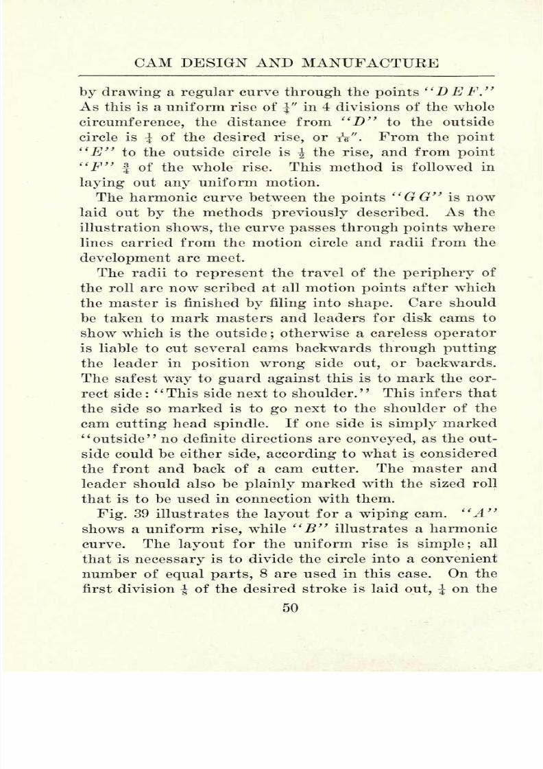
8/6/2019 Cam Design and Manufac
http://slidepdf.com/reader/full/cam-design-and-manufac 64/140
CAM DESIGN AND MANUFACTURE
by drawing a regular curve through the points "D E F."
As this is a uniform rise of J" in 4 divisions of the whole
circumference, the distance from "D" to the outside
circle is J of the desired rise, or iV". From the point
"E" to the outside circle is \ the rise, and from point
"F" f of the whole rise. This method is followed in
laying out any uniform motion.
The harmonic curve between the points "GG" is now
laid out by the methods previously described. As the
illustration shows, the curve passes through points where
lines carried from the motion circle and radii from the
development arc meet.
The radii to represent the travel of the periphery of
the roll are now scribed at all motion points after which
the master is finished
byfiling into shape. Care should
be taken to mark masters and leaders for disk cams to
show which is the outside;otherwise a careless operator
is liable to cut several cams backwards through putting
the leader in position wrong side out, or backwards.
The safest way to guard against this is to mark the cor-
rect side :
' '
This side next to shoulder.' '
This infers that
the side so marked is to
gonext to the shoulder of the
cam cutting head spindle. If one side is simply marked
"outside" no definite directions are conveyed, as the out-
side could be either side, according to what is considered
the front and back of a cam cutter. The master and
leader should also be plainly marked with the sized roll
that is to be used in connection with them.
Fig. 39 illustrates the layout for a wiping cam. "A"shows a uniform rise, while "B" illustrates a harmonic
curve. The layout for the uniform rise is simple; all
that is necessary is to divide the circle into a convenient
number of equal parts, 8 are used in this case. On the
first division | of the desired stroke is laid out, J on the
50

8/6/2019 Cam Design and Manufac
http://slidepdf.com/reader/full/cam-design-and-manufac 65/140
MASTEE CAMS
CO
I

8/6/2019 Cam Design and Manufac
http://slidepdf.com/reader/full/cam-design-and-manufac 66/140
CAM DESIGN AND MANUFACTURE
next division and so on. A regular curve drawn through
these points gives the line of motion.
The harmonic curve shown at "B" is laid out accord-
ing to the methods described with the master cam shown
in Fig. 38. The harmonic curve gives a very easy motion
to a wiping cam and, therefore, it should be used, unless
FIG. 40
it is necessary to have the follower rise with a uniform
motion. Where only a few wiping cams are to be madeit is, of course, not necessary to make a master as the
outline could be finished by filing, but in event of a large
number being required, a master should be made in the
regular way as previously described, and a leader cut
from it.
52

8/6/2019 Cam Design and Manufac
http://slidepdf.com/reader/full/cam-design-and-manufac 67/140
MASTEE CAMS
The layout for an eccentric cam is shown in Fig. 40,
whereinthe line
"A" equalsthe
stroke,the arcs "BB"
the periods of rest, and the divisions "CC" the periods
of action. This type of cam is readily laid out as it con-
FIG. 41
sists of four arcs only. The arcs representing the periods
of rest are drawn from the center, while the radii that
represent the periods of action are drawn from the points
"DD" where the periods of rest end. The period of
rest in any eccentric cam is determined by its stroke.
53
8/6/2019 Cam Design and Manufac
http://slidepdf.com/reader/full/cam-design-and-manufac 68/140
CAM DESIGN AND MANUFACTUEE
This is illustrated in Fig. 41, where six eccentric cams
of thesame outside diameter
areshown,
the strokes
ranging from"
to f ". As the illustration shows, the
period of rest is shortened as the stroke is increased.
In making masters for eccentric cams by the method
followed with ordinary machine cams, the process is long
and the results somewhat uncertain. In this case it
would be necessary to develop the line of motion by the
method shown inFig. 24, laying
out the master from the
outline thus obtained. More satisfactory results are ob-
tained by making the master of the size and shape desired
in the finished cam, as the method used in developing the
leader from the small master cam is simple and the re-
sults satisfactory. This method can also be used to ad-
vantage in making leaders for cutting automobile engine
cams.
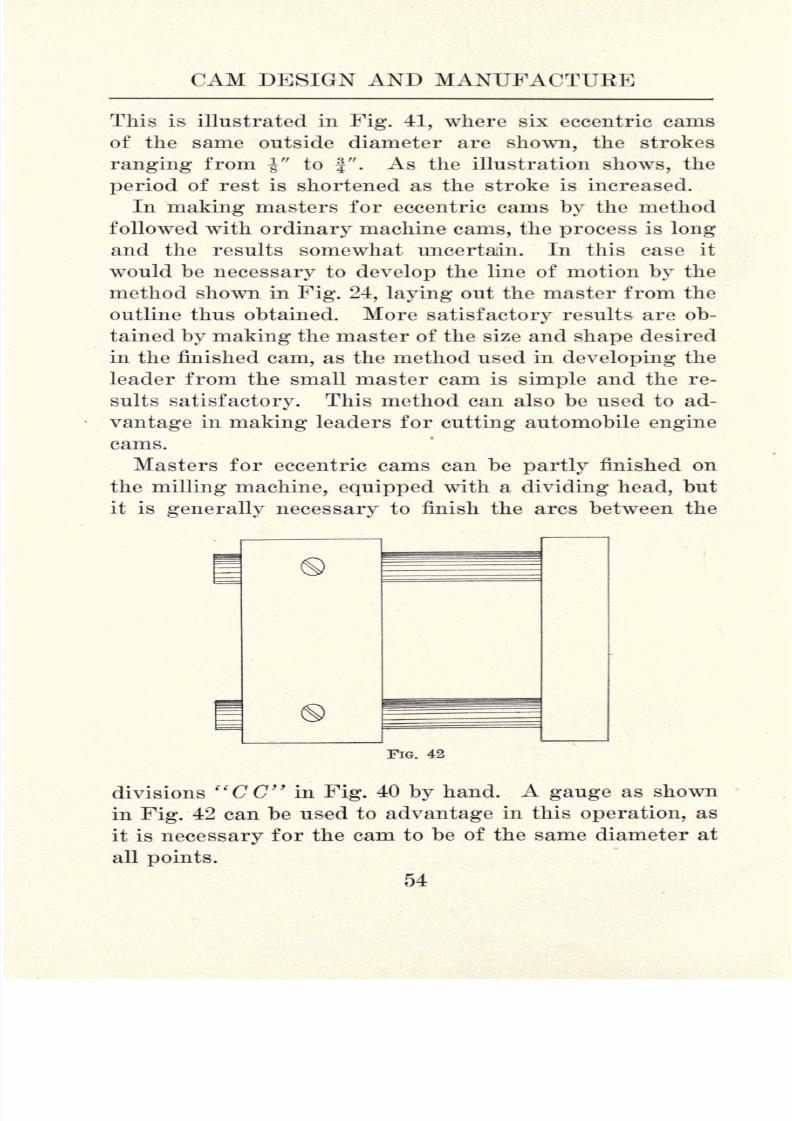
Masters for eccentric cams can be partly finished on
the milling machine, equipped with a dividing head, but
it is generally necessary to finish the arcs between the
FIG. 42
divisions "CC" in Fig. 40 by hand. A gauge as shown
in Fig. 42 can be used to advantage in this operation, as
it is necessary for the cam to be of the same diameter at
all points.
54

8/6/2019 Cam Design and Manufac
http://slidepdf.com/reader/full/cam-design-and-manufac 69/140
MASTER CAMS
Masters for tangential gas engine cams, which consist
of arcs andstraight
lines
only,
are readily made on a
vertical milling machine equipped with a revolving platen,
or by means of a dividing head used on a plain or uni-
versal milling machine. With cams of the type shown
F̂IG. 43
in Fig. 27 it is necessary to work out the greater part
of the outline by hand, which calls for the services of a
skilled workman.
In making a leader for cutting eccentric or automobile
55
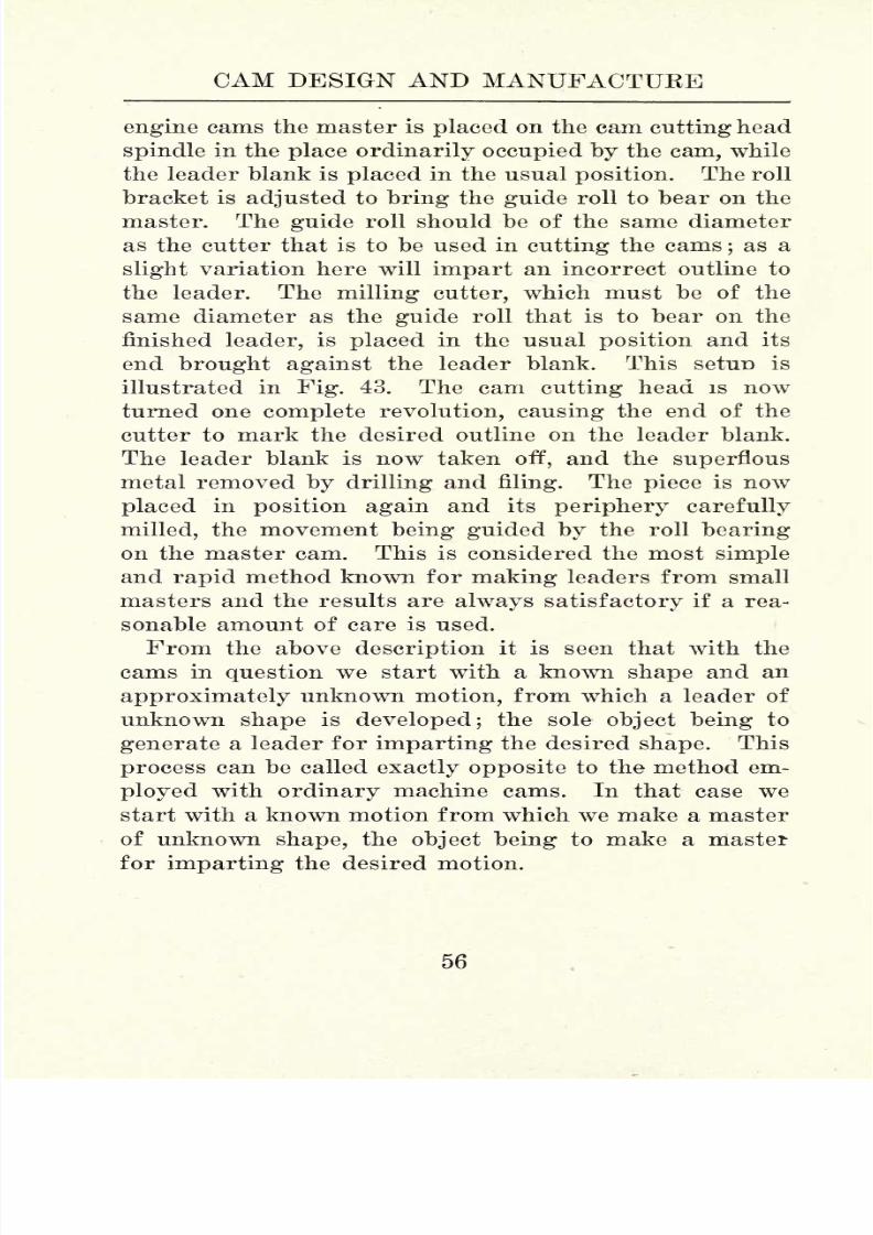
8/6/2019 Cam Design and Manufac
http://slidepdf.com/reader/full/cam-design-and-manufac 70/140
CAM DESIGN AND MANUFACTURE
engine cams the master is placed on the cam cutting head
spindle in the place ordinarily occupied by the cam, while
the leader blank is placed in the usual position. The roll
bracket is adjusted to bring the guide roll to bear on the
master. The guide roll should be of the same diameter
as the cutter that is to be used in cutting the cams;as a
slight variation here will impart an incorrect outline to
the leader. The milling cutter, which must be of the
same diameter as the guide roll that is to bear on the
finished leader, is placed in the usual position and its
end brought against the leader blank. This setun is
illustrated in Fig. 43. The cam cutting head is now
turned one complete revolution, causing the end of the
cutter to mark the desired outline on the leader blank.
The leader blank is now taken off, and the superflous
metal removed by drilling and filing. The piece is now
placed in position again and its periphery carefully
milled, the movement being guided by the roll bearing
on the master cam. This is considered the most simple
and rapid method known for making leaders from small
masters and the results are always satisfactory if a rea-
sonable amount of care is used.
From the above description it is seen that with the
cams in question we start with a known shape and an
approximately unknown motion, from which a leader of
unknown shape is developed; the sole object being to
generate a leader for imparting the desired shape. This
process can be called exactly opposite to the method em-
ployed with ordinary machine cams. In that case we
start with a known motion from which we make a master
of unknown shape, the object being to make a master
for imparting the desired motion.
56

8/6/2019 Cam Design and Manufac
http://slidepdf.com/reader/full/cam-design-and-manufac 71/140
CHAPTER V
MACHINE WORK PREPARATORY TO CUTTING AND
DIFFERENT TYPES OF CAM CUTTERS
Ordinary machine cams are made of various mate-
rials : Cast iron, malleable iron, gun iron, steel castings,
drop forgings, and sometimes from steel bar stock, in
cases where the cams are small and of the open type.
Close-grained cast iron is the material commonly used
as it is cheap, easily worked, and possesses good wear-
ing qualities. Malleable iron is sometimes used in cam
making, but it can not be claimed that this material
possesses any particular advantage. To be sure, malle-
able iron will withstand a greater bending strain than
cast iron, but cams, as a rule, are not subjected to bend-
ing strains, and for this reason cast iron is generally
preferred.
Gun iron is a good material to use in cam making as
it is stronger than cast iron and its cost is not prohib-
itive. Shoe machinery cams that have to remain accu-
rate under severe strains are often made of this material.
Steel castings and drop forgings are excellent materials,
for small cams that are to be hardened;the valve motion
cams on gas engines being a good example. Steel-bar
stock is a good material for small cams as it is readily
worked, and it can be case hardened. The methods used
for chucking out and turning up cast iron cams for ordi-
nary purposes are simple and need no explanation here
as they are known to every mechanic.
Automobile engine cams are generally made of drop
forgings, steel castings, or from bar-stock machinery
57
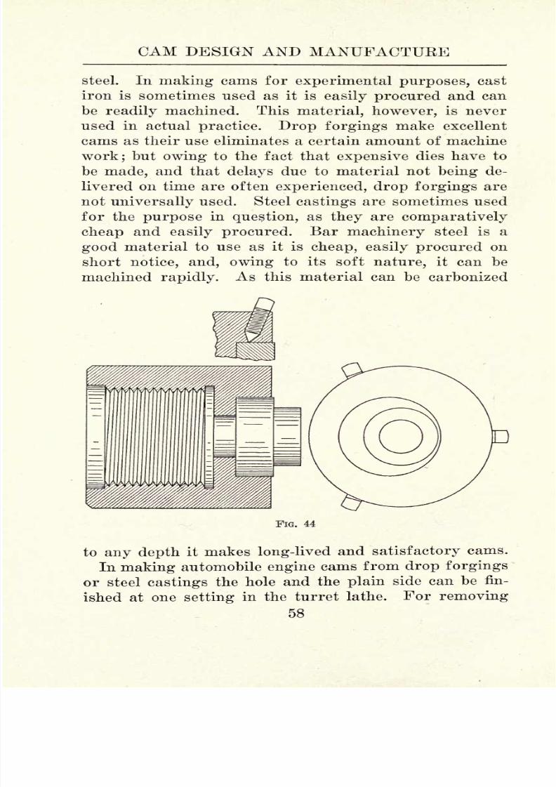
8/6/2019 Cam Design and Manufac
http://slidepdf.com/reader/full/cam-design-and-manufac 72/140
CAM DESIGN AND MANUFACTURE
steel. In making cams for experimental purposes, cast
iron is sometimes used as it is easily procured and can
be readily machined. This material, however, is never
used in actual practice. Drop forgings make excellent
cams as their use eliminates a certain amount of machine
work; but owing to the fact that expensive dies have to
be made, and that delays due to material not being de-
livered on time are often experienced, drop forgings are
not universally used. Steel castings are sometimes used
for the purpose in question, as they are comparatively
cheap and easily procured. Bar machinery steel is a
good material to use as it is cheap, easily procured on
short notice, and, owing to its soft nature, it can be
machined rapidly. As this material can be carbonized
FIG. 44
to any depth it makes long-lived and satisfactory cams.
In making automobile engine cams from drop forgings
or steel castings the hole and the plain side can be fin-
ished at one setting in the turret lathe. For removing
58

8/6/2019 Cam Design and Manufac
http://slidepdf.com/reader/full/cam-design-and-manufac 73/140
TYPES OF CAM CUTTEKS
the superflous stock from the other side, and from the
hub, good results can be obtained on the cam cutter bysubstituting a plain disk for the usual leader. As this
method calls for little attention, aside from changing the
pieces, it is used by many manufacturers.
In making cams from bar stock the material should
first be cut to nearly the required thickness;otherwise a
long bar of stock would have to be revolved eccentrically
in the turret lathe, which is not always practicable. Theturret-lathe tools for machining cams are quite simple
Q B Q 1
and can be made by any tool maker on short notice. Achuck for holding the blanks is illustrated in Fig. 44.
This fixture is screwed on the turret-lathe spindle. The
set screws for gripping the blanks are set at a slight
angle as the illustration shows, thus having a tendency
to hold the blank against its seat. The blank is spotted,
drilled, and reamed in the regular way, leaving a few
thousandths for finishing the hole by grinding after the
piece is hardened.
For cutting away the superfluous stock from the hub
of the cam, the tool shown in Fig. 45 can be used to good
5 59

8/6/2019 Cam Design and Manufac
http://slidepdf.com/reader/full/cam-design-and-manufac 74/140
CAM DESIGN AND MANUFACTURE
advantage. The head, which carries two cutters, is fas-
tened to the shankby
means of thetaper pin
"A." The
cutters should be made of high-speed steel. They are
held in position by the screws "B" and are adjusted by
the screwsUC." When the cutters become dull they can
be sharpened without taking them from the head. One
end of the shank "D" fits the hole previously chucked
in the cam and serves as a pilot for steadying the work.
This is
necessaryas the cut is
comparatively heavyand
off center.
The next point to consider is the manner in which the
cam is to be fastened to the cam shaft, as the means of
fastening are utilized as a locating point while shaping
the face of the cam. Keys, screws, or taper pins, as
FIG. 46
shown in Fig. 46 are used and all three methods, no
doubt, possess advantages. There is one important point
that should not be overlooked, viz.: all the cams of one
kind, that is inlet or exhaust, should be alike as regards
the relative position between the means of fastening and
the face of the cam. In cases where multiple-cylinder
engines are made this makes a reduction in production
costs while shaping the face of the cams. Again, the
necessity of carrying in stock cams for each cylinder of
multiple cylinder engines is eliminated. The differences
in position of the cams in relation to each other that are
necessary for timing the various valves are fixed by
60

8/6/2019 Cam Design and Manufac
http://slidepdf.com/reader/full/cam-design-and-manufac 75/140
TYPES OF CAM CUTTERS
spotting, keyseating, or drilling and taper-reaming the
camshaft,
as the case
may be,at the correct
placesto
give the proper timing.
Taper pins are considered satisfactory for locating
the cams and a simple jig for drilling and reaming the
cams is shown in Fg. 47. The cam blank slips over the
stud "A" and is located by the posts "B," which are
machined to fit the outline of the blank. After drilling,
thebushing "C"
is removed and the hole reamed to the
nA
ZD
FIG. 47
required depth by the reamer "D," which is provided
with a stop. This stop comes in contact with the lining
bushingand it is
adjustable;this
being necessaryas it
has to be re-set every time the reamer is sharpened.
The next point for consideration is the shaping of the
outline or contour of the sam. This can be done on the
cam cutter, or on a plain grinding machine equipped with
a suitable cam grinding attachment. On this point there
61

8/6/2019 Cam Design and Manufac
http://slidepdf.com/reader/full/cam-design-and-manufac 76/140
CAM DESIGN AND MANUFACTUEE
is a wide difference of opinion as to what is the best prac-
tice. With the modern, substantially built cam cuttingmachine, the cams can be readily formed from' round
stock as left by the screw machine. After hardening, the
contour can be finished on a disk grinder, thus insuring
a square face. Even if very slight irregularities in
contour result they will not be of enough importance to
effect the value motion materially.
On the other hand, the makers of grinding machinesclaim that grinding is an economical method to use for
roughing cam blanks from round stock and finishing
after hardening. Grinding with a disk wheel certainly
presents one objection in that the contour of the cam is
bound to change as the wheel wears away. When con-
fronted with the problem of installing machinery for
making automobile engine cams,it is
bestto
investigatethe various methods closely, and to be guided by good
common sense.
There are quite a few devices and special machines on
the market for cam cutting, and they all work on the
same principle : that is, the cam outline, or path, is gen-
erated by a follower bearing on the,periphery of a leader
which is cut from a master cam.A simple form of cam cutting attachment is illustrated
in Fig. 48. The spindle, which is driven by worm gear-
ing, is of ample dimensions and runs in bronze boxes
that are adjustable for wear. The cam and the leader
are held on an arbor that fits the spindle through the
medium of a tapered shank. The head carrying the
spindleis
bolted to the platenof the
attachmentand can
be set at right angles for cutting drum cams when occa-
sion requires. The roll bracket is adjustable to accom-
modate leaders of different diameters, and is bolted to
the inside of the base, as the illustration shows. For
cutting drum cams a different roll bracket is used. The
62

8/6/2019 Cam Design and Manufac
http://slidepdf.com/reader/full/cam-design-and-manufac 77/140
TYPES OF CAM CUTTERS
base of the attachment is fastened to the milling machine
platen in the regular way, and is provided with gibs for
FIG. 48
compensating for wear. This attachment was originally
designed to be fed by hand, but some enterprising me-
63
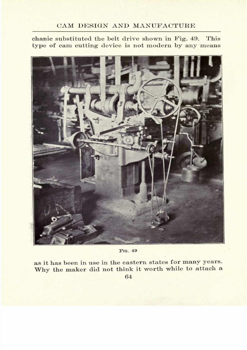
8/6/2019 Cam Design and Manufac
http://slidepdf.com/reader/full/cam-design-and-manufac 78/140
CAM DESIGN AND MANUFACTURE
chanic substituted the belt drive shown in Fig. 49. This
type of cam cutting device is not modern by any means
FIG. 49
as it has been in use in the eastern states for many years.
Why the maker did not think it worth while to attach a
64

8/6/2019 Cam Design and Manufac
http://slidepdf.com/reader/full/cam-design-and-manufac 79/140
TYPES OF CAM CUTTERS

8/6/2019 Cam Design and Manufac
http://slidepdf.com/reader/full/cam-design-and-manufac 80/140
CAM DESIGN AND MANUFACTURE
name plate to this product is a question of conjecture as
the attachment is efficient and not high in price.
Another practical cam cutting attachment is illustrated
in Fig. 50. This device is of the swing-frame type, the
frame being pivoted at its base. It is sometimes claimed
that this arrangement will not cut cams that are true to
the leader, owing to the swing motion. A little thought
will convince us that this assertion is not well grounded,
forif
the leaderis
cut onthis
machine from a masterthat is correct, any errors due to the swing motion can-
not develop. If, however, a leader should be cut on this
attachment and afterward used on a cam cutter of the
type previously described, a faulty contour in the finished
cam curve would result. The use of this device is limited
as it will cut face cams only.
The spindle is driven by a train of worm gearing, themain gear being enclosed in the frame casting. The
main gear is driven by the worm shaft "A," this in turn
being driven by the worm shaft "B" and worm wear
"E." The frame is pivoted at "F" and the leader is
held in contact with the guide roll "G" through the
medium of the lever "H" to which a weight is attached.
The handle "J" is for hand feeding, the automatic feed
being disengaged by the lock nut "K." The feed shaft
"B" is driven by a universal joint shaft actuated by the
feed mechanism of the milling machine on which the at-
tachment is used.
In Figs. 51 and 52 is illustrated a modern machine de-
signed and built by the Garvin Machine Company to
meet a popular demand for a minimum-sized cam cutting
machine. This machine is well adapted for cutting face
and drum cams, also for the use of lubricant, in cases
where cams are to be cut from steel. The general design
follows closely the standard as used on the Garviu
66

8/6/2019 Cam Design and Manufac
http://slidepdf.com/reader/full/cam-design-and-manufac 81/140
TYPES OF CAM CUTTERS
Machine Company's well-known 24" and 36" sized profile
machines.
The spindle slide is sensitive, running on large steel
balls in steel tracks. This feature insures exact duplica-
FIG. 51
tion of the desired contour as the factor of faulty con-
tact, owing to a hard working slide, is eliminated. The
drive is from an overhead counter-shaft through the
medium of a universal joint shaft.
67

8/6/2019 Cam Design and Manufac
http://slidepdf.com/reader/full/cam-design-and-manufac 82/140
CAM DESIGN AND MANUFACTUEE
The rail slide is nicely balanced, being operated by a
rotary nut equipped with a ball thrust. This feature
gives a rapid motion for the removal of the cutter and
guide roll at the completion of the cam cutting operation.
FIG. 52
While changing cams, the spindle slide is clamped, and
at the completion of the change the slide returns to a
positive micrometer stop. All the gears on this machine
are protected by adequate guards, thus conforming to
the laws passed in many states regarding the safeguard-
ing of machinery.
68

8/6/2019 Cam Design and Manufac
http://slidepdf.com/reader/full/cam-design-and-manufac 83/140
TYPES OF CAM CUTTEBS
The spindle bearings are of the type used on profile
machines and areprovided
with means forcompensating
for wear. The feed can be disengaged or reversed as
occasion requires. The fixtures for cutting face cams
can be readily removed and the attachment for drum
cams substituted. Fig. 51 shows the machine set for
cutting face cams, while Fig. 52 illustrates the drum cam
fixture in position.
This machine is
compact, occupyingless than a
squareyard of floor space. The design is a radical departure
from that commonly seen in cam-cutting practice as the
leader and cam are fastened to separate revolving tables.
This is, indeed, a decided improvement as, owing to the
secure support, the factor of chattering is practically
eliminated, thus making it possible to force the cutter to
its
maximum output.
69

8/6/2019 Cam Design and Manufac
http://slidepdf.com/reader/full/cam-design-and-manufac 84/140
CHAPTEE VI
CAM CUTTING
The cutters for machining cam contours do not differ
in design from ordinary end mills. The teeth may be
spiral or straight, the shanksstraight
or tapered, and
the material carbon or high-speed steel. High-speed
steel cutters are, of course, the most economical even at
their advanced cost as their use reduces production costs
to a minimum. Spiral cutters are preferred since their
use eliminates chattering. The spiral on a right-hand
cutter should be left hand. This feature insures smooth
cutting.
Whereright
hand cutters withright
hand
spirals are used, the tendency is to pull the cutter away
from its holder and, if tapered shank cutters are used,
broken cutters and spoiled work will often result. Three
of the cutters shown in Fig. 53 are right-hand cutters
with left-hand spirals. Although a left-hand spiral on a
right-hand cutter causes the end teeth to cut with a slight
drag,
this is of little
consequence.In Fig. 53, "A" illustrates an ordinary taper shank
cutter. This type possesses one advantage; that is, it
can be obtained from any supply house on short notice.
Otherwise no particular advantage is gained by its use.
A bevel-shank cutter is shown a,t"B." In making these
cutters, the shank beyond the bevel is left soft, the thread
beingfinished after the cutter is hardened. As the work
on the bevel, thread and teeth is finished on centers,
after the cutter is hardened, all parts are concentric.
This is of course necessary to insure good work.
Another form of bevel shank cutter is shown at "C."
The thread is of coarse pitch and fitted loosely to com-
70

8/6/2019 Cam Design and Manufac
http://slidepdf.com/reader/full/cam-design-and-manufac 85/140
CAM CUTTING
pensate for irregularities due to hardening. The bevel
and teeth are finished concentric
bygrinding. In re-
sharpening these cutters, they should be located from
the bevel in a holder provided for this purpose. If held
between centers, the teeth will not be concentric with the
bevel if the cutter happens to be sprung a little, which
is generally the case with cutters that have been in use
PIG. 53
for some time. A shell cutter is shown at "D." These
are easily and cheaply made but they are not reliable as
the thread that holds the cutter in position weakens both
the cutter and its arbor. A double fly-tooth cutter is
shown at "E." These are sometimes used for roughing
out cam paths. It is claimed that this design allows the
chips to work away from the cut readily. On the other
hand, the fact that there are only two teeth is taken by
many mechanics as a decided objection.
A teazel, or finishing cutter, is shown a.t"F." It is a
well known fact that ordinary cutters when used for
finishing wear undersize in a very short time. For this
reason the use of teazels is recommended on accurate
71
8/6/2019 Cam Design and Manufac
http://slidepdf.com/reader/full/cam-design-and-manufac 86/140
CAM DESIGN AND MANUFACTURE
cam paths. As the* teeth of the teazel are not relieved,
theyhold their size for a
longtime. Teazels can be
straight or spiral and both forms will give good results.
A spiral cut teazel is shown at "G." The teazel shown
at "H" is double cut, this design being popular in some
manufacturing centers.
FIG. 54
Anymechanic
whohas
attemptedto cut accurate
campaths in cast iron has experienced the annoyance that
develops while taking the finishing cut with an ordinary
spiral cutter. If the cutter is not perfectly ground it
will cause chattering, and, even under ideal conditions,
it will sometimes crawl, thus making the path over-size.
These difficulties are wholly overcome by the use of
teazels forfinishing
cuts.
Ateazel
removesstock
byscraping and, therefore, it should not be used directly
after a roughing cutter, but after a finishing cutter that
is from 0.002" to 0.005" under size.
An efficient holder for straight-shank cutters is shown
in Fig. 54 and Fig. 55, while Fig. 56 shows a few cutters
and teazels that are used in connection with it. The shell
"A," whichis
splitin
four places,is
compressed by thepressure brought to bear on its ends by the nut "B."
Thus it grips the cutter shank firmly. Several fillers of
different inside diameters are provided for various sized
cutter shanks. One of these fillers is shown at "C."
This cutter holder should be accurately made, and the
72

8/6/2019 Cam Design and Manufac
http://slidepdf.com/reader/full/cam-design-and-manufac 87/140
CAM CUTTING
FIG. 55
FIG. 56
73
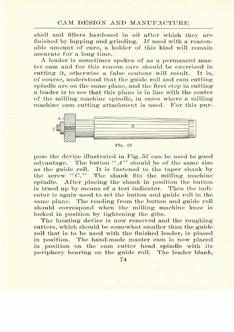
8/6/2019 Cam Design and Manufac
http://slidepdf.com/reader/full/cam-design-and-manufac 88/140
CAM DESIGN AND MANUFACTURE
shell and fillers hardened in oil after which they are
finished
by lappingand
grinding.If used with a reason-
able amount of care, a holder of this kind will remain
accurate for a long time.
A leader is sometimes spoken of as a permanent mas-
ter cam and for this reason care should be exercised in
cutting it, otherwise a false contour will result. It is,
of course, understood that the guide roll and cam cutting
spindle are on the same plane, and the first step in cutting
a leader is to see that this plane is in line with the center
of the milling machine spindle, in cases where a milling
machine cam cutting attachment is used. For this pur-
57
pose the device illustrated in Fig. 57 can be used to good
advantage. The button "A" should be of the same size
as the guide roll. It is fastened to the taper shank by
the screw "C." The shank fits the
milling
machine
spindle. After placing the shank in position the button
is trued up by means of a test indicator. Then the indi-
cator is again used to set the button and guide roll in the
same plane. The reading from the button and guide roll
should correspond when the milling machine knee is
locked in position by tightening the gibs.
Thelocating
device is now removed and the
roughingcutters, which should be somewhat smaller than the guide
roll that is to be used with the finished leader, is placed
in position. The hand-made master cam is now placed
in position on the cam cutter head spindle with its
periphery bearing on the guide roll. The leader blank,
74
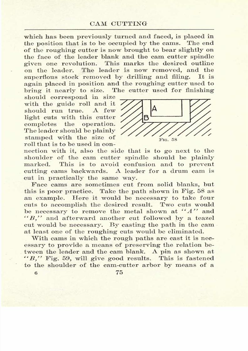
8/6/2019 Cam Design and Manufac
http://slidepdf.com/reader/full/cam-design-and-manufac 89/140
CAM CUTTING
FIG. 58
which has been previously turned and faced, is placed in
the position that is to be occupied by the cams. The end
of the roughing cutter is now brought to bear slightly on
the face of the leader blank and the cam cutter spindle
given one revolution. This marks the desired outline
on the leader. The leader is now removed, and the
superflous stock removed by drilling and filing. It is
again placed in position and the roughing cutter used to
bring it nearly to size. The cutter used for finishing
should correspond in size_
with the guide roll and it
should run true. A few
light cuts with this cutter
completes the operation.
The leader should be plainly
stamped with the size of
roll that is to be used in con-
nection with it, also the side that is to go next to the
shoulder of the cam cutter spindle should be plainly
marked. This is to avoid confusion and to prevent
cutting cams backwards. A leader for a drum cam is
cut in practically the same way.
Face cams are sometimes cut from solid blanks, but
this is poor practice. Take the path shown in Fig. 58 as
an example. Here it would be necessary to take four
cuts to accomplish the desired result. Two cuts would
be necessary to remove the metal shown at "A" and
"B," and afterward another cut followed by a teazel
cut would be necessary. By casting the path in the cam
at least one of the roughing cuts would be eliminated.
With cams in which the rough paths are cast it is nec-
essary to provide a means of preserving the relation be-
tween the leader and the cam blank. A pin as shown at
"B," Fig. 59, will give good results. This is fastened
to the shoulder of the cam-cutter arbor by means of a
6 75

8/6/2019 Cam Design and Manufac
http://slidepdf.com/reader/full/cam-design-and-manufac 90/140
CAM DESIGN AND MANUFACTURE
drive fit. It should be of sufficient diameter to avoid
shearing off and slightly undersize to allow it to enter
the locating hole in the cam. As both the leader and cam
are located by the same pin it is necessary that the locat-
FIG. 59
ing holes correspond, otherwise the contour on the leader
and the cast path in the cam will not be in the correct
relation. A good means for locating the hole in the cam
correctly is to have a spot cast on it for starting the
drill; the drilling to be done with the simple jig shown
76

8/6/2019 Cam Design and Manufac
http://slidepdf.com/reader/full/cam-design-and-manufac 91/140
CAM CUTTING
at "C." The jig is held in position by means of the
plug "D,"which fits the center hole of the cam, the
spot referred to serving to start the drill in the proper
place.
Many cams are made with multiple paths as shown at
"A." With these cams it is necessary that the locating
holes in the leaders be in the proper places to give the
correct timing in the finished cam. The locating hole in
the cam must also be correctly placed. To accomplish
this the following method will prove satisfactory. As
the relation between the two paths in the cam "A" is
known, the two leaders should be set one over the other
in relation to give the proper timing. This can be de-
rived from the original cam chart as laid out by the
draftsman. The two leaders are now drilled together
to fit the locating pin. The next step is to make a metal
pattern from which the cam castings are to be made. A
plain blank is used for this purpose. After turning and
facing to the desired dimensions a locating hole is drilled
with the jig previously mentioned. The blank is now
placed in position on the cam cutter and the paths cut.
The paths should be undersize enough to allow stock for
finishing, the amount to leave depending on the dimen-
sions of the cam. In spacing the paths the correct dis-
tance from the center, allowance for shrinkage should be
made. The paths should be cut with a tapered cutter to
allow for draft. This saves profanity on the part of the
molder and insures clean castings. The locating hole is
now plugged up and a spot made in the same place. This
spot is for starting the drill as previously described.
After correct patterns for casting the cams have been
made, and leaders for cutting them provided, the opera-
tion of cutting cams is quite simple and good results will
be obtained 'if the few important points that follow are
observed. Some of these suggestions have been pre-
77

8/6/2019 Cam Design and Manufac
http://slidepdf.com/reader/full/cam-design-and-manufac 92/140
CAM DESIGN AND MANUFACTUBE
viously referred to but it will do no harm to mention
them again.The machine should be properly oiled; not when the
operator happens to feel like it, but at regular intervals.
Once a day is not too often when the machine is in con-
stant use. If the operator allows the ways of the sliding-
table type of machine to become dry faulty cams are
liable to be the result.
Never use several hundred pounds of iron for a weightwhen fifty pounds are sufficient. Fig. 49 gives a good
illustration of this error. Excessive weight throws an
undue strain on the attachment as the guide roll is
always well to one side. Again, the combination of ex-
cessive weight and constant rolling contact is liable to
wear the leader out of true contour.
Make sure that the leaderis
placedin the correct
posi-
tion; for if placed on backwards, spoiled work will re-
sult. Leaders should always be marked to show which
side goes next to the shoulder;not in meaningless hiero-
glyphics that are understood by the operator only, but
in plain English that can be read at a glance. Care
should also be used to see that the guide roll is of the
correctdiameter,
as a variation here will
generatean
incorrect motion.
Don't drive the cam in position. If it does not fit,
there is, in all probability, a reamer in the tool room that
will correct the error. Driving cams on and off is a
waste of time, and generally ends in springing the arbor
out of shape. A sprung arbor will often prove the means
ofrendering
valueless several hundred cams before the
error is detected.
Use sharp cutters and make sure that they run true.
When cutters run out of true, an undue strain is forced
on the few teeth that do the cutting. Finishing cutters
should run true, for if they run out the path will be
78'

8/6/2019 Cam Design and Manufac
http://slidepdf.com/reader/full/cam-design-and-manufac 93/140
CAM CUTTING
larger at the bottom than it should be. Never attempt
to cut a full
pathfrom solid stock at one cut as chatter-
ing and a broken cutter will result.
In cases where very accurate paths are called for, a
teazel should be used for the final finishing, but do not
expect the teazel to do the work of a finishing cutter.
Owing to its design, a teazel will not remove more than
a few thousandths of an inch at best.
Whencutting
steel cams useplenty
of
lubricant,either
cutting oil or cutting compound. This should be deliv-
ered to the work by means of a drip feed not from an
oil can when the operator happens to think of it. Never
attempt to teazel steel cams this is uncalled for and it
is not practicable.
In cutting open cams in cases where accuracy of con-
tour is
necessary,use a
finishing
cutter of the same size
as the roll that is to be used with the finished cam as a
slight variation will often result in noticeable error.
79

8/6/2019 Cam Design and Manufac
http://slidepdf.com/reader/full/cam-design-and-manufac 94/140
CHAPTER VII
CAM CUTTING CONTINUED
UNUSUAL CAM PROBLEMS
The following unusual cam problems may be of inter-
est to those seeking general information on the subjectof cams. At "A" Fig. 60 is shown a sharp rise that is
FIG. 60
sometimes used in connection with open cams. The con-
stant action of the roll at this point soon wears the cam
as shown by the dotted line in "B." To overcome this
objection, the cam is reinforced at this point by means
of the hardened piece shown at "C." This piece can beheld in place by screws or rivets.
FIG. 61
Path cams are often reinforced on new as well as
repair work. An illustration of this is shown in Fig. 61.
80

8/6/2019 Cam Design and Manufac
http://slidepdf.com/reader/full/cam-design-and-manufac 95/140
CAM CUTTING
As it is not always good practice to make cams of this
typeof
steel, owingto the
high productioncost thus in-
curred, it is a good plan to reinforce the portion of the
path subjected to the most wear. The piece "A," which
is held in position by screws, is made of tool steel, and
FIG. 62
after being fitted in position, it is taken out and hard-
ened in cyanide and oil. These illustrations will, no
doubt, bringto the mind of the
practicalman
manyin-
stances wherein new as well as worn cams can be rein-
forced to advantage.
It is sometimes necessary to cut scroll cams as shown
in Fig. 62. A cam of this type, which often has a move-
ment of over one revolution, is generally actuated by a
81

8/6/2019 Cam Design and Manufac
http://slidepdf.com/reader/full/cam-design-and-manufac 96/140
CAM DESIGN AND MANUFACTURE
rack meshing with a gear on the cam shaft. The master
cam is made of brass in the regular way, but it should be
reinforced at the back as shown in Fig. 63, otherwise the
pressure of the roll would throw it out of shape. The
leader is made of cast iron, being cut from the master in
the usual way. As it resembles an ordinary path cam,
fU\ ^IT\ fU\ fV\ /A fU\

8/6/2019 Cam Design and Manufac
http://slidepdf.com/reader/full/cam-design-and-manufac 97/140

8/6/2019 Cam Design and Manufac
http://slidepdf.com/reader/full/cam-design-and-manufac 98/140
CAM DESIGN AND MANUFACTUBE
serted piece the guide roll and its stud and bracket would
receive a strain that
might injurethem.
A novel cam, sometimes used in sewing machine con-
struction is illustrated in "A" Fig. 65. This is a switch
cam, so called because the movement is changed every
-Follower
FIG. 65
revolution, two revolutions being necessary to complete
the full stroke of the cam. On first
thought,
it
appearsthat this type of cam would be difficult to cut, but in
reality the operation is simple. One leader, as shown
at"B" is used, and two cuts are made to complete the
continuous path. A fixed follower, as shown at "C" is
used with cams of this kind as a roll follower would be
84

8/6/2019 Cam Design and Manufac
http://slidepdf.com/reader/full/cam-design-and-manufac 99/140
CAM CUTTING
liable to become wedged at the crossing of the path.
This movement is inclined to be short-lived, owing to thefriction between the path and the fixed follower. Not-
withstanding this objection, however, cams of this type
can often be used to advantage.
E-
FIG. 66
An application of this cam movement to the valvemechanism of a single-cylinder, four-cycle, internal com-
bustion engine is illustrated in Fig. 66. In this case the
switch cam takes the place of the usual half-time shaft.
"A" is the crank shaft, "B" the exhaust cam, "C" its
follower, "D" the push rod, "E" the valve stem, "F"the switch cam, "G" its follower, "H" the follower shaft
housing, "I" the arm that is interposed between the
push rod and the valve stem, and "J" the sliding button
that transmits the motion of the push rod to the valve
stem. As the exhaust valve of a four-cycle engine is
operated but once every other revolution of the crank
shaft, the switch cam provides an end to this means as
85

8/6/2019 Cam Design and Manufac
http://slidepdf.com/reader/full/cam-design-and-manufac 100/140
CAM DESIGN AND MANUFACTURE
FIG. 67
the button "J" is moved from its position between the
push rod and valve stem every other revolution, thus
preventing the valve from being raised.
A simple plate-cam movement, as shown at "A" Fig.
86
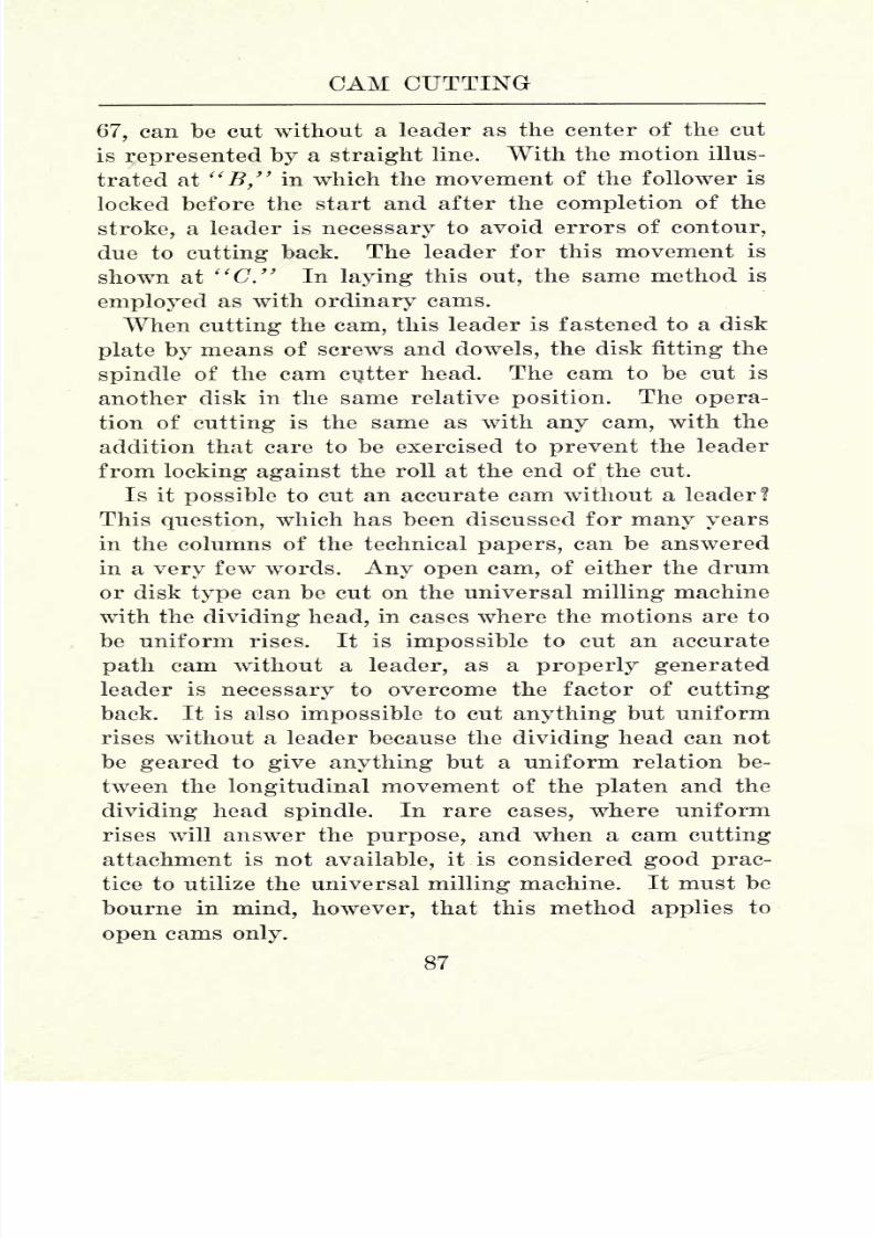
8/6/2019 Cam Design and Manufac
http://slidepdf.com/reader/full/cam-design-and-manufac 101/140
CAM CUTTING
67, can be cut without a leader as the center of the cut
is
represented byastraight
line. With the motion illus-
trated at "B," in which the movement of the follower is
locked before the start and after the completion of the
stroke, a leader is necessary to avoid errors of contour,
due to cutting back. The leader for this movement is
shown at "C." In laying this out, the same method is
employed as with ordinary cams.
When cutting the cam, this leaderis
fastenedto a disk
plate by means of screws and dowels, the disk fitting the
spindle of the cam cutter head. The cam to be cut is
another disk in the same relative position. The opera-
tion of cutting is the same as with any cam, with the
addition that care to be exercised to prevent the leader
from locking against the roll at the end of the cut.
Is it possible to cut an accurate cam without a leader?This question, which has been discussed for many years
in the columns of the technical papers, can be answered
in a very few words. Any open cam, of either the drum
or disk type can be cut on the universal milling machine
with the dividing head, in cases where the motions are to
be uniform rises. It is impossible to cut an accurate
path cam without a leader, as a properly generatedleader is necessary to overcome the factor of cutting
back. It is also impossible to cut anything but uniform
rises without a leader because the dividing head can not
be geared to give anything but a uniform relation be-
tween the longitudinal movement of the platen and the
dividing head spindle. In rare cases, where uniform
rises will answer the purpose, and when a cam cutting
attachment is not available, it is considered good prac-
tice to utilize the universal milling machine. It must be
bourne in mind, however, that this method applies to
open cams only.
87

8/6/2019 Cam Design and Manufac
http://slidepdf.com/reader/full/cam-design-and-manufac 102/140
CAM DESIGN AND MANUFACTURE
A movement that can be generated directly on the
milling machine is illustrated in
Fig.
68. The movement
. 68
is as follows : first a rest of 90, then a drop of \" in 50,followed by a rest of 40, next a rise of V in" 150, then
a drop of \" in 30. After the blank has been turned
and faced the move-
ment is laid out and
the superfluous stock re-
moved by drilling and
filing. The piece is now
placed between the di-
viding head centers, be-
ing securely held on a
work arbor. The mill-
ing should be done with
a half round convex
cutter of the same ra-
dius as the roll that is
to be used with the fin-
ished cam. The principle of the method in question is
shown in Fig. 69.
88

8/6/2019 Cam Design and Manufac
http://slidepdf.com/reader/full/cam-design-and-manufac 103/140
CAM CUTTING
In setting up the dividing head, a plate having a circle
of
eighteen
holes is used, two holes representing one de-
gree. In milling the cam 360 finishing cuts will be taken.
If the cam has been previously filed to say within iV" of
the desired size, roughing cuts can be dispensed with,
provided a fine feed is used.
After setting the cutter to the required depth, the first
90 of the contour are milled into 90 cuts. In milling
the drop of \" in 50 the platen is raised 0.10" before
taking each cut. The rest of 40 is finished by taking 40
cuts without disturbing the set of the platen. In milling
the rise of V in 150 the platen is dropped 0.006|"
before each cut. The platen should be dropped below
the desired setting and brought to position with an up
motion to eliminate errors that might arise through
backlash. In finishing the drop of \" in 30 the platen is
raised 0.16f"before each cut. This finishes the outline,
bringing the cutter to the starting point. The contour
of the cam now presents 360 slight ridges which can
readily be removed by filling.
Another method of cutting cams without leaders con-
sists of gearing up the dividing head to turn the desired
number of
degrees
while the platen advances the re-
quired distance to generate the rise. A drum cam can
be held between centers in the usual way. With a disk
cam, the dividing head is set at an angle of 90 with the
platen, the cam being held on a special arbor. In this
case the cutter is driven by a vertical milling attachment.
The method in question will give good results if the
operator uses extreme care, both in figuring out the
leads and in milling the rises. Where there is a cam
cutting attachment available it is best to use it, even if
only a few cams are wanted. A good mechanic, who
thoroughly understands laying out and cutting cams,
can often make a leader in the time that would be con-
89
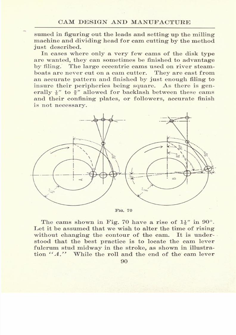
8/6/2019 Cam Design and Manufac
http://slidepdf.com/reader/full/cam-design-and-manufac 104/140
CAM DESIGN AND MANUFACTURE
sumed in figuring out the leads and setting up the milling
machine and dividing head for cam cutting by the method
just described.
In cases where only a very few cams of the disk type
are wanted, they can sometimes be finished to advantage
by filing. The large eccentric cams used on river steam-
boats are never cut on a cam cutter. They are cast from
an accurate pattern and finished by just enough filing to
insure their peripheries being square. As there is gen-
erally -J" to |" allowed for backlash between these cams
and their confining plates, or followers, accurate finish
is not necessary.
FIG. 70
The cams shown in Fig. 70 have a rise of 1-J" in 90.
Let it be assumed that we wish to alter the time of rising
without changing the contour of the cam. It is under-
stood that the best practice is to locate the cam lever
fulcrum stud midway in the stroke, as shown in illustra-
tion "A" While the roll and the end of the cam lever
90

8/6/2019 Cam Design and Manufac
http://slidepdf.com/reader/full/cam-design-and-manufac 105/140
CAM CUTTING
both move in arcs, as the illustration shows, the actual
timing, as cut on the cam contour, is accurately conveyedto the machine parts that are actuated. If, for experi-
mental or other purposes, it is desirable to alter the tim-
ing slightly without changing the cam, we can accom-
FIG. 71
plish this by offsetting the fulcrum stud as shown at
"B." Here the fulcrum is placed on a line with the
start of the cam rise. As the lever moves over its ful-
crum it draws the roll away from the center line of the
cam, thus the cam stroke in this particular case is com-
7 91

8/6/2019 Cam Design and Manufac
http://slidepdf.com/reader/full/cam-design-and-manufac 106/140
CAM DESIGN AND MANUFACTURE
pleted in 82 instead of 90, as originally laid out. Thus
the motion is shortened
by8. This
practiceincurs a
factor that is sometimes detrimental as the end of the
lever moves to one side of the line of converted motion.
If the cam were rotated in the opposite direction of that
shown by the arrow, the movement would be prolonged ;
that is, the stroke would be completed in 98. Offsetting
the fulcrum stud is sometimes advantageous while ex-
perimentingwith cam
movements, although
it cannot be
called good practice in the strictest sense of the word.
The machine designer is occasionally confronted with
the problem of providing a cam movement with a vari-
able rise. This can be accomplished by using the adjust-
able fulcrum stud illustrated in Fig. 71. The stud "A,"
which is slightly flattened on two sides, is held in posi-
tion in its slot
bythe nut "B." The stud bushing "C"
is also flattened, being locked in position in a slot in the
cam lever "D" by means of the nut "E." The bushing
is held in position on the stud by the nut "F." When
this nut is tightened the bushing must, of course, have
slight clearance to move freely on the stud. In chang-
ing the stroke, the two slots are first brought in line, as
shown in the illustration, and the nuts "B" and "E"
loosened. Then the stud is moved to a position in the
slots to impart the desired stroke, after which the nuts
are tightened. This feature is simple in construction
and efficient in results.
Sometimes occasions arise wherein it is desirable to
provide a cam having a variable timing. To accomplish
this an adjustable cam is necessary A cam of this type
is illustrated in Fig. 72. The movement consists of a
rest period of 180 followed by a drop of I" in 52|, a
rest of 75, and a rise of 1" in 52^. In this case the
problem is to provide means to shorten the 75 period of
rest. The cam is made in two pieces, the cam proper
92

8/6/2019 Cam Design and Manufac
http://slidepdf.com/reader/full/cam-design-and-manufac 107/140
CAM CUTTING
being provided with a hub over which the supplementary
piecerotates. The two sections are
clamped togetherby a stud and nut. The stud is fastened to the supple-
mentary piece by means of a drive fit, moving in the slot
in the cam proper. Both sections are cut at one opera-
tion, the stud being clamped in the position in the illus-
FIG. 72
tration. To shorten the stroke, the stud nut is loosened
and the cam rises brought toward each other to the de-
siredposition
wherethey
are heldby tightening
the stud
nut. One roll, long enough to cover both sections, is
used with this cam. The cam is shown at its full period
of rest of 75. By closing up the cam, this rest period
can be eliminated entirely. This, of course would
lengthen the long period of rest by 75. It is possible to
93

8/6/2019 Cam Design and Manufac
http://slidepdf.com/reader/full/cam-design-and-manufac 108/140
CAM DESIGN AND MANUFACTUEE
construct a great variety of adjustable cams but the one
described will serve to illustrate theprinciple.Two types of cam rockers are shown in Fig. 73. As
before stated, one use of these is to lift the valves of the
beam engines used on side-wheel steamboats. The move-
ment is driven by an eccentric on the paddle-wheel shaft
FIG. 73
through the medium of the rod "E." There are many
methods in use for generating the curves on these cam
rockers, all of which, no doubt, possess advantages. The
following methods, which are very simple have often
been used to advantage. The movement shown at "A"
gives the toe piece "C" a rist of 2" while the lever "D"travels through an arc of 45. To lay out this move-
ment, a chart, as shown in "A" Fig. 74, is drawn. This
represents the rise of 2" divided into eight equal parts
by the lines 1, 2, 3, 4, 5, 6, 7, and 8. Dimension "B"
corresponds to the distance from the rock shaft to the
rod carrying the toe piece, dimension "C" corresponds
to the radius of the rocker hub, while dimension "D"
94

8/6/2019 Cam Design and Manufac
http://slidepdf.com/reader/full/cam-design-and-manufac 109/140
CAM CUTTING
equals the distance from the center of the toe-piece rod
to the middle of the toe piece. "E" is a
templatemade
of heavy paper. Dimensions "H" and "C" correspond.
The desired angle of 45 is included between lines "0"
and "8" on the template. This angle is divided into
eight equal parts by the lines 0, 1, 2, 3, 4, 5, 6, 7, and 8.
The template is fastened in its correct relative position
by means of a thumb tack, the top line "F" coinciding
with line "0" on the chart. The template is now moved
until its line "1" is opposite line "G." Line "1" on
FIG. 74
the chart is now continued over the template. The tem-
plate is again moved until lines "2" and ".G" coincide
and line "2" of the chart carried over the template. This
process is continued until line "8" is drawn. The tem-
plate is now in the position shown in the illustration.
It is seen that a curve has been generated on the tem-
plate. This is the desired curve for the rocker.
While the above is an easy working motion it possesses
a disadvantage as practically all the bearing on the toe
95

8/6/2019 Cam Design and Manufac
http://slidepdf.com/reader/full/cam-design-and-manufac 110/140
CAM DESIGN AND MANUFACTUEE
piece is in the vicinity of the line "J." This can be
overcome by using the rocker shown at "B," Fig.73.
This rocker has a curve that bears on the toe piece with
a long, rocking motion. To lay out this curve we can
proceed as shown in Fig. 75. The lines "A A" equal
the desired rise, dimensions "B and C" being in the
U-B-
iFIG. 75
same relative position as those shown in Fig. 74. From
a point on the line "D" an arc is drawn that connects
the end of
upperline
"A"and the circle
representingthe radius of the rocker hub. By drawing the chart
"F," and making the template "G" which is pivoted in
the correct position by means of a thumb tack, it is a
simple matter to demonstrate that the bearing point
moves along the toe piece as it is raised. In this case,
96

8/6/2019 Cam Design and Manufac
http://slidepdf.com/reader/full/cam-design-and-manufac 111/140
CAM CUTTING
the point of applied power is changed as the toe piece
rises,and as the
leverageis decreased in like
proportion,more power is exerted at the completion of the stroke
than at the beginning. To avoid throwing an undue
strain on the eccentric and its rod, the lever "F," Fig,
73, should at least equal the distance from the end of the
toe piece to the point directly over the rocker shaft.
Cam rockers of the kind in question are never cut on a
cam cutter. Thetype
shown
at"A,"Fig. 73, is laid out
by means of a sheet metal template, made according to
the method described, and generally finished by filing,
care being exercised to make sure that the bearing sur-
face is square. As the rocker shown at "B," Fig. 73,
is nothing more or less than an arc, the piece can be
strapped to the face plate of the lathe, or the platen of
the boring mill, and the correct radius finished by
turning.
97

8/6/2019 Cam Design and Manufac
http://slidepdf.com/reader/full/cam-design-and-manufac 112/140
CHAPTER VIII
CAM GRINDING
Some years ago, in the days of fine-grit, close-bonded
emery wheels, cam grinding was practically unknown.
At the present time, however, owingto the
developmentof grinding machines and grinding wheels, cam grinding
has become common practice, especially in the auto-
mobile industry. Any open cam, whether hard or soft,
can be finished accurately by grinding if its surface does
not present concavaties or less radius than that of the
grinding wheel used.
The attachments,or
fixtures,for
cam grindingcan be
divided into two distinct types : Those employing regular
disk wheels, and those calling for the use of cup or
cylinder wheels. Where extreme accuracy as regards
contour is desired, it is necessary to use a cup or cylin-
der wheel, for when a disk wheel is used the contour of
the cams that are ground is bound to change slightly as
thewheel
wearsaway.
Thischange
is notvery
notice-
able, and it is of little importance with automobile engine
cams. With eccentric cams, however, where it is neces-
sary for the cam to fill the space between the followers
at all times, a cup or cylinder wheel is necessary.
The only important argument in favor of the disk
wheel for cam grinding is that it cuts faster than a cylin-
der wheel. Thisargument
is
opento
exceptions,how-
ever, as excellent results as regards cost production can
be obtained with the fixture shown in Fig. 76. This fix-
ture, which was designed for use on a vertical spindle
grinding machine, consists principally of a base on which
is mounted a swing-frame for carrying the leader and
98
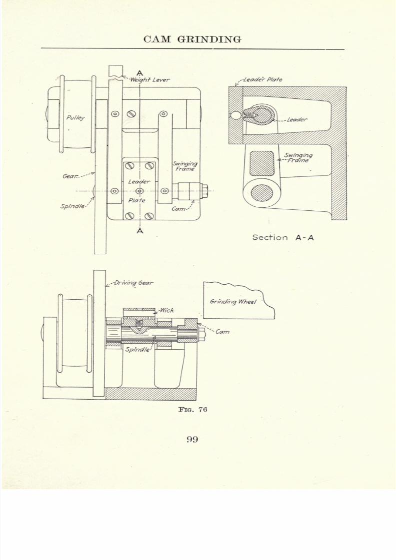
8/6/2019 Cam Design and Manufac
http://slidepdf.com/reader/full/cam-design-and-manufac 113/140
CAM GEINDING
Pulley
Gear--'"
Spindle*'
4--- ^
A'-Weight Lever
Leader
-4-Plate
SwingingFrame
Cam-'
Section A-A
FIG. 76
99

8/6/2019 Cam Design and Manufac
http://slidepdf.com/reader/full/cam-design-and-manufac 114/140
CAM DESIGN AND MANUFACTURE
cam spindle. This spindle is driven by a spur gear
which in turn is drivenby
apulley through
the medium
of a pinion. A hardened and ground plate takes the
place of the usual guide roll, the leader being held in
contact with this plate by means of a lever and weight.
The plate is provided with an oiling device consisting of
a chamber packed with wick, or felt. This keeps the face
of the leader lubricated at all times, thus eliminating un-
necessaryfriction.
While in use, this attachment should be protected by
a sheet metal cover, otherwise the centrifugal action of
the grinding wheel would throw grit into the working
parts. This fixture is simple and practical, and, if prop-
erly constructed, it will give entire satisfaction. It pos-
sesses one slight disadvantage that is, the surface speed
of thespindle
is
alternatelyretarded and accelerated
bythe planetary action of the driving gear over its pinion.
This, however, is not a serious detriment.
The grinding wheel should be of a coarse combination
grit and soft grade. For roughing out cams from soft
stock a combination grit with 16 for a base, or a straight
24 grit will give good results. For the finishing of cams
afterthey
have beenhardened,
the wheel should be of a
softer grade and somewhat finer in grit 20 or 24 for the
base of the combination. A combination grit will give
the best results for the finishing operation. These grits
may seem coarse to one who is not conversant with the
fundamental principles of grinding with a high speed
cylinder wheel. In this case it is the combination of
coarsegrit,
soft
grade,and
highwheel
speedthat
givesthe desired results.
While grinding, the cam should be rotated very slowly
8 to 15 revolutions per minute. A medium traverse
feed should be used iV advance for each revolution of
the work. While roughing out cams from soft stock, the
100

8/6/2019 Cam Design and Manufac
http://slidepdf.com/reader/full/cam-design-and-manufac 115/140
CAM GRINDING
wheel should be fed down as much as the work will stand
at each complete stroke of the platen. This has to bedetermined by experiment as local conditions have to be
given consideration in practically every case. For the
finishing operation, after the cams have been hardened,
a few light cuts only are necessary. Under ordinary con-
ditions, 0.010" should be an ample allowance. When
grinding cams that are to be held in position of their
shafts by means of a tapered pin,alocating key provided
w^ith a teat should be used. The key fits a slot milled in
the spindle for this purpose while the teat enters the
hole to be occupied by the tapered pin. If a tapered
pin were used for locating the cams on the fixture, the
spindle would become sprung in time, through driving
the pin in position.
The original master camis left soft and is used for
finishing a permanent hardened leader. The fixture in
question can be depended upon to finish with absolute
accuracy as regards contour. When the leader becomes
worn, a new one should be substituted. For finishing
new leaders from time to time, a hardened master, ground
from the original soft master should be preserved. This
master should beplainly
marked as a means of identifi-
cation. It is also necessary occasionally to face off the
hardened plate as it becomes worn in time through con-
tact with the leader.
A fixture for grinding accurate eccentric cams is illus-
trated in Fig. 77. The cams in question enter into the
construction of shoe machinery. The cam and its leader
are both mounted on an arbor that is held between cen-
ters, this arbor being driven by means of a worm gear
and worm. In this particular instance the cam is held in
position by means of a tapered pin. The fixture shown
is of the swing type, with the guide roll on the side away
from the grinding wheel. In this case a concaved leader
101

8/6/2019 Cam Design and Manufac
http://slidepdf.com/reader/full/cam-design-and-manufac 116/140
DESIGN AND MANUFACTURE
is necessary to generate a convex cam. When the leader
becomes worn it
should,
of
course,
be re-finished. The
method employed for this operation will be explained
later. It is claimed that the reversed, or concaved leader
is a very efficient design as it tends to eliminate chatter-
FIG. 77
ing without bringing an undue strain on the guide roll
and leader, which is sometimes the case when a heavy
weight is used.
The cams in question, two of which are shown in Fig.
78, are made of steel castings, case hardened. In grind-
ing them, a slow work speed is used 10 revolutions per
minute. Approximately 0.01" is left for finishing. The
platen is actuated by an automatic feed, advancing gV for
each revolution of the cam. The wheel is 46 grit, Kgrade, and is run at a surface speed of 5,000 feet per
102

8/6/2019 Cam Design and Manufac
http://slidepdf.com/reader/full/cam-design-and-manufac 117/140
CAM GRINDING
minute. As the illustration shows, the work is ground
dry whichcurtails
productionto some extent.
While the process of grinding these cams is simple and
readily comprehended by any mechanic, the method used
in generating the leader is novel and worthy of consid-
eration. By referring to Fig. 79 it is seen that the grind-
ing wheel is removed and that a guiding device is fas-
tened to the end of the wheel spindle. The outer plate
of this device is
adjustableand is set to bear on the face
of the master cam with medium pressure. This master
\
FIG. 78
cam, which is accurately made, fills the guide at all
points as it revolves. With the master cam and leader
blank in position on the arbor the desired outline is
scribed on the blank by means of a surface gauge. One
revolution of the leader accomplishes this. The scriber
of the surface gauge should be set central with the arbor.
While scribing this line the roll bracket is removed.
The leader is now removed, filled approximately to the
desired shape, and again placed in position. A teazel
103

8/6/2019 Cam Design and Manufac
http://slidepdf.com/reader/full/cam-design-and-manufac 118/140
CAM DESIGN AND MANUFACTUEE
made of high-speed steel is now placed in the position
occupied bythe
guideroll. This teazel is driven
byan
overhead belt as the illustration shows. As the swing
movement of the fixture is now controlled by the master
cam revolving between two fixed plates, the leader can
. 79
be brought in contact with the teazel by means of the
cross feed. By taking a few light cuts, the outline of the
leader is made to correspond to the motion generated by
the master. It is necessary for the teazel to be of the
same diameter as the roll used in connection with the
leader. In event of the loader becoming worn out of
shape through use, it can be corrected readily by the
method used in finishing a new leader. In Fig. 80 is
shown the teazel, which is made integral with its arbor,
104
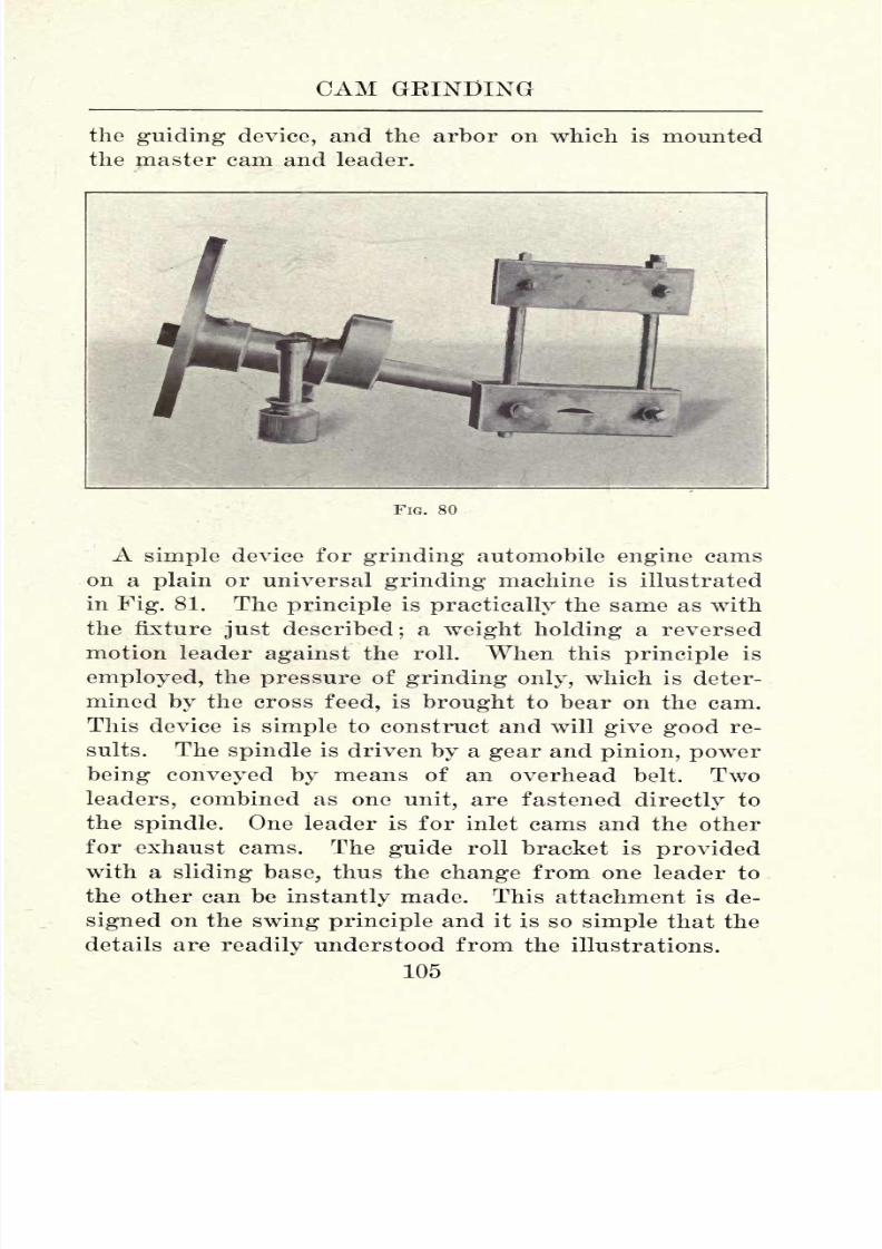
8/6/2019 Cam Design and Manufac
http://slidepdf.com/reader/full/cam-design-and-manufac 119/140
CAM GRINDING
the guiding device, and the arbor on which is mounted
the master cam and leader.
FIG. 80
A simple device for grinding automobile engine cams
on a plain or universal grinding machine is illustrated
in Fig. 81. The principle is practically the same as with
the fixture just described; a weight holding a reversed
motion leader against the roll. When this principle is
employed, the pressure of grinding only, which is deter-
mined by the cross feed, is brought to bear on the cam.
This device is simple to construct and will give good re-
sults. The spindle is driven by a gear and pinion, power
being conveyed by means of an overhead belt. Two
leaders, combined as one unit, are fastened directly to
the spindle. One leader is for inlet cams and the other
for exhaust cams. The guide roll bracket is provided
with a sliding base, thus the change from one leader to
the other can be instantly made. This attachment is de-
signed on the swing principle and it is so simple that the
details are readily understood from the illustrations.
105

8/6/2019 Cam Design and Manufac
http://slidepdf.com/reader/full/cam-design-and-manufac 120/140
CAM DESIGN AND MANUFACTURE

8/6/2019 Cam Design and Manufac
http://slidepdf.com/reader/full/cam-design-and-manufac 121/140
CAM GEINDING
With any cam grinding fixture it is necessary to pro-
vide means for
shapingthe leaders
accurately.
With
the fixture in question, the leaders are generated on the
milling machine;the principle employed being shown in
Fig. 82. The master cam is held in contact with the
master plate by means of a weight applied to the lever.
Master Cam
'Master 'Plate
FIG. 82
As the motion is the reverse of that used while grinding,
a cord running over an overhead pulley has to be used.
The master cam generates the motion over the master
plate, while the milling cutter, which is of the same size
as the guide roll, mills the correct contour on the leader.
While milling the leaders, the attachment should be fed
slowly by means of an overhead belt connected to the
driving pulley. The master plate is made of cast iron,
the contour being turned to the diameter of the grinding
wheel. The hole in the base is for convenience in strap-
ping to the milling maching platen.
Where extreme accuracy is desired, the master plate
can be re-turned to different radii to correspond to dif-
ferent wheel diameters. Thus, if leaders were to be gen-
erated to be used in connection with wheels of 18, 17, 16,
15, and 14 inches, we would have five sets of leaders.
After generating the first set for the 18" wheel, the mas-
8 107
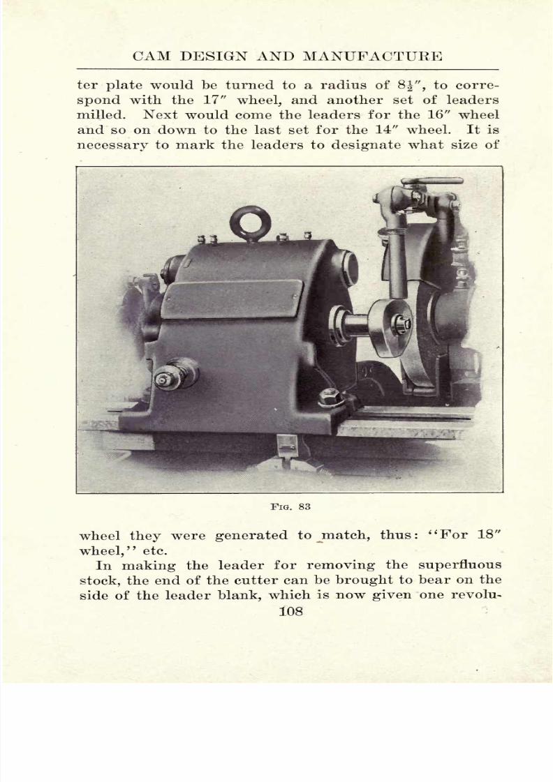
8/6/2019 Cam Design and Manufac
http://slidepdf.com/reader/full/cam-design-and-manufac 122/140
CAM DESIGN AND MANUFACTUKE
ter plate would be turned to a radius of 8", to corre-
spond with the 17" wheel, and another set of leadersmilled. Next would come the leaders for the 16" wheel
and so on down to the last set for the 14" wheel. It is
necessary to mark the leaders to designate what size of
FIG. 83
wheel they were generated to jnatch, thus :
i t For 18"
wheel/7
etc.
In making the leader for removing the superfluous
stock, the end of the cutter can be brought to bear on the
side of the leader blank, which is now given one revolu-
108
8/6/2019 Cam Design and Manufac
http://slidepdf.com/reader/full/cam-design-and-manufac 123/140
CAM GEINDING
tion which causes the cutter to mark the desired outline.
Thesuperfluous
stock can now be removedby
drilling
and filing, or directly on the milling machine by means
of several cuts. In finishing, light cuts should be taken
and the leader should be fed slowly. The cutter must be
of the same diameter as the roll to be used on the leaders.
Also, it must run true and be set to bring it central with
the spindle of the attachment, when it is at the highest
point of the ark caused by the swing motion.
FIG. 84
Another device for
grindingindividual cams is shown
in Fig. 83. This is a product of The Landis Tool Com-
pany and is designed for use with their plain and uni-
versal grinders. The device is constructed on the swing
principle, with the work and the leader on the same
spindle. A novel feature of this device is that it grinds
109

8/6/2019 Cam Design and Manufac
http://slidepdf.com/reader/full/cam-design-and-manufac 124/140
CAM DESIGN AND MANUFACTUEE
its own leaders from actual sized models, or masters.
This feature is worth careful consideration for two rea-
sons: It eliminates the roundabout process previously
described, and makes possible the construction of accu-
rate hardened leaders. In the cam grinding fixture under
consideration the leader operates against a stationary
guide, or shoe plate, instead of the customary roll. Sev-
eral guides are provided having radii to correspond to
different wheel diameters. When a new wheel is
mounted,say 18" diameter, a plate to correspond to this diameter
FIG. 85
is used. When the wheel is worn to a diameter of 17",
the 18"plate
is removed and one thatcorresponds
to the
17" wheel substituted. By this arrangement, errors in
contour due to wheel wear are eliminated.
While the general design of the device in question
are clearly shown in the illustration, the principle can
perhaps be better understood by referring to Pig. 84.
110

8/6/2019 Cam Design and Manufac
http://slidepdf.com/reader/full/cam-design-and-manufac 125/140
CAM GRINDINGlj
' :''' ' " '
The master cam, "A," and the leader to be generated,
"B,"are mounted on the shaft "C." The radius of the
master plate, "D," and the grinding wheel, "E," are the
same. It is evident that the master, running over the
master plate, is bound to impart the desired contour to
the leader.
For the actual grinding of the cams, the leader thus
generated is placed in the proper position against the
master plate as shown in Fig. 85. In this case large
leaders are generated from small masters. In commer-
cial cam grinding, however, better results are obtained
by employing large leaders to generate small cams. In
illustrating the principle used in compensating for wheel
wear, let it be assumed that the leader, "B," was gen-
erated on an 18" wheel, the motion being derived from a
master running over a master plate of 9" radius. After
the wheel has worn to a diameter of 17", for instance,
as shown by the dotted line, it is evident that a very
slight change in contour will result. Now, if we substi-
tute a plate having a contour to correspond to the wheel,
as the dotted line on the plate shows, it is obvious that
we have equalized conditions. It is readily seen that the
principle is not unlike that illustrated in the device for
use with the cylinder wheel as shown in Fig. 76. In the
first instance we work on planes, while in the second case,
radii are substituted.
"With the development of multiple-cylinder automobile
and airplane engines a demand arose for a grinding
device for finishing cams made integral with the cam
shaft. A means to this end is illustrated in the attach-
ment shown in Fig. 86. This is also a product of The
Landis Tool Company, being designed for use on their
plain and universal grinders.
This unit was designed to produce the necessary cam
contours demanded by automobile engineers for function-
Ill
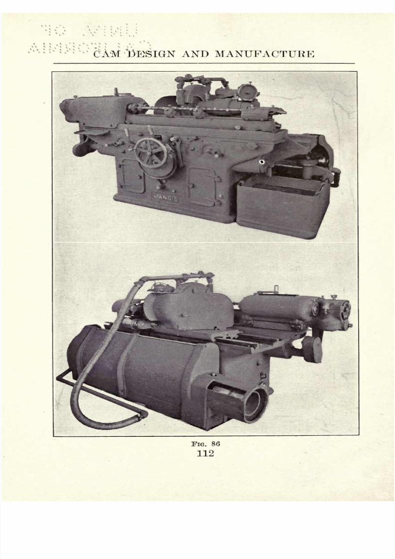
8/6/2019 Cam Design and Manufac
http://slidepdf.com/reader/full/cam-design-and-manufac 126/140
1
CAM 'DESIGN AND MANUFACTURE
FIG. 86
112

8/6/2019 Cam Design and Manufac
http://slidepdf.com/reader/full/cam-design-and-manufac 127/140
CAM GRINDING
ing the valves of internal combustion engines with a high
degreeof
efficiency.
Theswinging
bracket that contains
the master cams and their spindle is of tubular cross sec-
tion being supported directly under the master cams and
work centers, close to the machine bed. The object of
this construction is to balance the swing bracket so that
strains are eliminated. As the work is carried directly
over the fulcrum center, vertical movement and the
changeof
grindingcontact on the wheel
peripheryis
reduced to a minimum. Thus the difference in cam
contour caused by wheel wear is slight. The master cam
is mounted directly on the headstock spindle in line with
the work so that lost motion is eliminated. The master
cam is kept in contact with its roll through the medium
of compression springs, the tension being adjustable to
suitvarying
conditions.
Accurate work is assured when the grinding wheel is
of a diameter equal to that of the roll used in contact with
the model cam used to generate the contour on the master
cam. Errors in cam grinding due to wheel wear are
caused by the contact between the work and the grinding
wheel traveling above and below the wheel center. The
greater the variation of grinding wheel contact from thecenter, the more pronounced the variation in the contour
of cams ground with different sized wheels will be. In
the machine illustrated, the work is swung equal distances
from a point directly over the fulcrum center so that the
work moves practically in a horizontal plane.
In Fig. 87, the camshaft, A, is driven by the dog, B,
which in turn is driven by the driver, (7, mounted on the
spindle, E. This driver is adjustable to facilitate setting
the camshaft in the correct relation with the master cam.
The spindle, E, is driven by the worm wheel, F. The
master cams, G, are mounted directly on the spindle by
means of a taper and a nut. Roller, H, makes contact
113

8/6/2019 Cam Design and Manufac
http://slidepdf.com/reader/full/cam-design-and-manufac 128/140
CAM DESIGN AND MANUFACTURE
with the master cams and is moved from cam to cam by
thelever,
I. The relative
position
of the master cam
roll is designated by the pointer, J. Through the medium
of a cam on the shaft, K, the roll is disengaged from the
master cam by a half turn of the lever, 7. The roll is
shifted to the next cam by completing the turn of lever I.
FIG. 87
A brake, L, is provided on the master cam spindle with
the object of compensating for any lost motion which
would be transferred to the cam as the pressure is re-
versed when passing over the highest point of contour.
A cross section and end elevation of the device is shown
in Fig. 88.
The selection of wheels for cam grinding on a cylin-
drical grinding machine is a simple problem as we have
only two factors to consider : Whether we desire to rough
out soft cams, removing as much stock as possible in a
given length of time, or whether we desire to finish
hardened cams, removing only a few thousandths of an
inch.
We can take as an example the cams made from bar
stock as shown in Fig. 44. As these cams come from the
114

8/6/2019 Cam Design and Manufac
http://slidepdf.com/reader/full/cam-design-and-manufac 129/140
CAM GRINDING

8/6/2019 Cam Design and Manufac
http://slidepdf.com/reader/full/cam-design-and-manufac 130/140
CAM DESIGN AND MANUFACTURE
turret lathe they are in the form of eccentrics. The de-
sired contour can be formed on the grinder, before the
cam is hardened, in a rapid and efficient manner by using
a coarse, free-cutting wheel. A 24 straight grit wheel
in P grade will give excellent results. This grade mayseem rather hard to use on a cylindrical grinder, but it
must be taken into consideration that the operation is a
roughing one, wherein the wheel must be hard enough to
stand up well under a heavy cut. Plenty of water should
be used, and the cam fed directly to the wheel. The
traverse feed should be discarded altogether. Approxi-
mately 0.10" should be left for the final finishing after
hardening.
In grinding individual cams that have been hardened,
24 combination grit, L grade will be found satisfactory.
Here, a slight traverse feed should be used in connection
with a wide faced wheel. Thus, if we were finishing
cams having a V face, a wheel with a 2" face could be
used. The traverse feed should be just enough to allow
the edge of the wheel to overlap the edge of the cam a
slight distance, say iV.
Cams made integral with their shafts are drop forged
with a liberal allowance for finishing. Sometimes the
ends and the sections between the several cams are
roughed out in the lathe but equally good results are ob-
tained by using the roughing wheel above referred to,
grinding from the rough stock. The same wheel is then
used for roughing out the cam contours. These cam
shafts are carbonized, or pack hardened, after which they
are straightened to correct errors caused by the sudden
contraction in the cooling bath, while the piece was red
hot. In the final finishing, the ends and the sections be-
tween the cams should be ground enough to remove the
scale, leaving the work several thousandths of an inch
over size. Next the cams are ground to size, and last of
116

8/6/2019 Cam Design and Manufac
http://slidepdf.com/reader/full/cam-design-and-manufac 131/140
CAM GEINDING
all the straight portions are finished. The 24 combina-
tion grit, L grade wheel can be used for this purpose.
Occasionally, we find manufacturers who prefer an
extra final finishing of the cam contours by hand. In
FIG. 89.
this case a fine-grit abrasive cloth is used. This opera-
tion is illustrated in Fig. 89. While a semi-polished
117

8/6/2019 Cam Design and Manufac
http://slidepdf.com/reader/full/cam-design-and-manufac 132/140
CAM DESIGN AND MANUFACTURE
surface is imparted it is obvious that the amount of stock
removed is practically nil. Whether this final finishingis good practice is purely a question of conjecture and a
matter of personal taste. Grinding machine and grind-
ing wheel manufacturers inform us that the grinding
wheel alone imparts the necessary finish, and, to clinch
their argument, they cite numerous automobile manu-
facturers who follow this practice.
On the other hand, the photograph from which Fig. 89was reproduced was taken by the author in one of the
large automobile manufacturing (not assembling) plants
in Detroit, Mich. This final hand finishing, which calls
for the services of a skilled workman, imparts a super-
fine surface, to be sure, but whether this finish is neces-
sary from a practical point of view must be decided by
themanufacturer
himself.
Taken as a whole, cam grinding by any of the methods
described is a compartively simple operation, once the
operator thoroughly understands the fundamental prin-
ciples of the work. This is necessary, as no workman
should grope along in the dark as it were; he should
understand thoroughly every step of his work and the
reasonsfor the different
operations.It is
impossibleto
set any hard and fast rules, as every rule generally has
an exception, and local conditions have to be given con-
sideration in many cases.
118

8/6/2019 Cam Design and Manufac
http://slidepdf.com/reader/full/cam-design-and-manufac 133/140
INDEX
Abrasives for Cam Roll Lapping, 34
Advantages of Spiral Cutters, 70
Allowance for Grinding, 36
Altering Time of Cams, 90
Angularity Chart, 19
Arbor for Cam Eoll Grinding, 37
Attachment for Cam Cutting, 62
Automobile Engine Cam Grinding
Fixture, 105
Automotive Engine Cams, 23
Barrel Cams, 2
Cam,
Barrel, 2
Continuous Motion, 26
Disc, 1
Drum, 1
Eccentric, 4
Plate, 17
Switch, 84
Tangential, 25
Wiping, 3
Cams,
Automotive Engine, 23
Cutting without Leaders, 87
Drilling Jig for, 61
Filing to Size, 90
Hand Finishing of, 117
Laying Out, 5
Locating on Shaft, 60
Machining, 61
Master, 45
Material for Making, 57
Multiple Path, 77
Open, 1
Path, 2
Reinforced, 80
Scroll, 81
Typical, 13
Variable Timing of, 92
Cam Blank Chuck, 59
Cam Chart, 5
Compound, 7
For Gas Engine Valves, 21
Cam Curves, 7
Cam Cutter,
Feed for, 63
Garvin, 66
Swing Frame, 66
Cam Cutting,
Attachment, 62
Safety Device, 83
Suggestions for, 77
Tools, 70
Cam Fastenings, 60
Cam Followers, 30
Cam Gauge, 54
Cam Grinding, 98
Fixtures, 98
Selecting Wheels for, 114
Wheel Shapes, 98
Cam Leaders,
Principle of, 110
Teazling, 104
Cam Leavers, 41
Cam Problems, Unusual, 80
Cam Rocker, 16, 41
Machining, 94
Cam Roll Grinding, 35
Arbor for, 37
Cam Roll Lapping, Abrasives for, 34
Cam Roll Laps, 34
Cam Roll Studs, Finishing, 38
Cam Rolls, 33
Finishing of, 33
Method of Grinding, 37
119

8/6/2019 Cam Design and Manufac
http://slidepdf.com/reader/full/cam-design-and-manufac 134/140
INDEX
Cam Teazle, 71
Cam With Variable Rise, 92
Cast Cam Paths, 75
Chart, Angularity, 19
Chart, Cam, 5
Chuck for Cam Blanks, 59
Compound Cam Chart, 7
Continuous Motion Cam, 26
Curves, Cam, 7
Cutter Holder, 72
Cutting Back, 11
Cutting Cams Without Leaders, 87
Cutting Leaders, 74
Cutting Master Cams, 55
Cutting Plate Cams, 87
Disadvantages of Fixed Followers, 30
Disadvantages of Path Cams, 2
Disk Cam, 1
Master for, 48
Drilling Jig for Cams, 61
Drum Cam, 1
Master for, 45
Drum Cams, Wear of, 3
Eccentric Cam, 4
Grinding Fixture, 101
Laying Out, 53
Master for, 54Uses of, 4
Eccentric Cams,
Grinding, 102
Making Leaders for, 103
Exhaust Cam, Layout of, 22
Exhaust Valve Opening, Theory of,
18
Fastenings for Cams, 60
Feed for Cam Cutter, 63
Filing Cams to Size, 90
Finishing Cam Eoll Studs, 38
Finishing Cam Rolls, 33
Fixed Followers, Disadvantages of,
30
Fixture for Grinding,
Automobile Engine Cams, 106
Cam Rolls, 35
Eccentric Cams, 101
Fixtures for Cam Grinding, 98
Follower for Switch Cam, 84
Followers, Cam, 30
Garvin Cam Cutter, 66
Gas Engine Valves, Cam Chart for,
21
Gauge for Cams, 54
Generating Leaders for Automobile
Engine Cams, 107
Grinder for Individual Cams, Lan-
dis, 109
Grinder for Integral Cams, Landis,
111
Grinding Allowance, 36
Grinding of Cam Rolls, 35
Grinding Cams, 98
Grinding Eccentric Cams, 102
Grinding Fixture for Cam Rolls, 35
Hand Finishing of Cams, 117
Holder for Cutters, 72
Landis Cam Grinder for Individual
Cams, 109
Landis Grinder for Integral Cams,111
Lapping, Necessity of, 36
Laps for Cam Rolls, 34
Laying Off Rocker Cams, 94
Laying Out Cams, 5
Laying Out Eccentric Cams, 53
Layout of Exhaust Cam, 22
Leader for, Scroll Cam, 82
Switch Cam, 84Leaders for,
Automobile Engine Cams, Gen-
erating, 107
Cutting, 74
Eccentric Cams, Making, 103
Lever, Swinging, Use of, 40
120

8/6/2019 Cam Design and Manufac
http://slidepdf.com/reader/full/cam-design-and-manufac 135/140
INDEX
Levers, Cam, 41
Locating Cam on Shaft, 60
Machine Cams, 61
Machining Cam Rockers, 94
Master Cams, 45
Cutting, 55
Master for,
Disc Cam, 48
Drum Cam, 45
Eccentric Cam, 54
Wiping Cam, 50Materials for Cam Making, 57
Method of Grinding Cam Bolls, 37
Movement for Plate Cam, 86
Movement of Piston, 21
Multiple Path Cams, 77
Objections to Open Cams, 2
Open Cams, 1
Objections to, 2
Path Cams, Disadvantages of, 2
Piston Movement, 21
Plate Cam, 17
Movement, 86
Plate Cams, Cutting, 87
Principle of Cam Leaders, 110
Push Eod Wear, 39
Keinforced Cams, 80
Rocker, Cam, 16, 41
Rocker Cams,
Laying Off, 94
Steamboat, 94
Rolls, Cam, 33
Safety Device, Cam Cutting, 83
Scroll Cam, Leader for, 82
Scroll Cams, 81
Spiral Cutters, Advantages of, 70
Steamboat Rocker Cams, 94
Suggestions for Cam Cutting, 77
Swing Frame Cam Cutter, 66
Swinging Lever, Use of, 40
Switch Cam, 84
Switch Cam Follower, 84
Switch Cam Leader, 84
Switch Cam for Valve Motion, 85
Tangential Cams, 25
Teazel for Cams, 71
Teazling Cam Leaders, 104
Theory of Exhaust Valve Opening,
18
Time of Cams, Altering, 90
Tools for Cam Cutting, 70
Typical Cams, 13
Unusual Cam Problems, 80
Uses of Eccentric Cam, 4
Valve Motion Switch Cam, 84
Variable Rise Cam, 92
Variable Timing of Cams, 92
Wear of Drum Cams, 3Wear on Push Rods, 39
Wheel Shapes for Cam Grinding, 98
Wheels for Cam Grinding, Select-
ing, 114
Wiping Cam, 3
Wiping Cam, Master for, 50
121

8/6/2019 Cam Design and Manufac
http://slidepdf.com/reader/full/cam-design-and-manufac 136/140
THE LITERATURE OF THE
SCIENCES AND ENGINEERING
On our shelves is the most complete stock of
technical, industrial, engineering and scientific
books in the United States. The technical liter-
ature of every trade is well represented, as is also
the literature relating to the various sciences,
both the books useful for reference as well as
those fitted for students' use as textbooks.
A large number of these we publish and for an
ever increasing number we are the sole agents.
ALL INQUIRIES MADE OF US ARE CHEER-
FULLY AND CAREFULLY ANSWEREDAND COMPLETE CATALOGS AS WELL AS
SPECIAL LISTS SENT FREE ON REQUEST
D. VAN NOSTRAND COMPANY
Publishers and Booksellers
8 WARREN STREET NEW YORK

8/6/2019 Cam Design and Manufac
http://slidepdf.com/reader/full/cam-design-and-manufac 137/140

8/6/2019 Cam Design and Manufac
http://slidepdf.com/reader/full/cam-design-and-manufac 138/140
THIS BOOK IS DUE ON THE LAST DATESTAMPED BELOW
AN INITIAL FINE OF^25 CENTSWILL BE ASSESSED FOR FAILURE TO RETURNTHIS BOOK ON THE DATE DUE. THE PENALTYWILL INCREASE TO SO CENTS
ON THE FOURTHDAY AND TO $1.OO ON THE SEVENTH DAYOVERDUE.
ENGiNEEF

8/6/2019 Cam Design and Manufac
http://slidepdf.com/reader/full/cam-design-and-manufac 139/140
YC 33174
CQ32M3QS63
raiy
UNIVERSITY OF CALIFORNIA LIBRARY

8/6/2019 Cam Design and Manufac
http://slidepdf.com/reader/full/cam-design-and-manufac 140/140


