Call: Email - scafco.com · SCAFCO offers a series of high quality products to meet the emerging...
72
Transcript of Call: Email - scafco.com · SCAFCO offers a series of high quality products to meet the emerging...

www.SCAFCO.com
SCAFCO Spokane2800 E. Main AveSpokane, WA 99202509-343-9000
SCAFCO Stockton2525 S. Airport WayStockton, CA 95206209-670-8053
SCAFCO Steel FramingWith 60 years of manufacturing experience, SCAFCO has gained a worldwide reputation for high-quality products, great customer service, and strong corporate ethics. Our comprehensive team of engineers, administrative and office staff, and craftsmen focus on providing customer driven products. We currently have manufacturing facilities in Spokane, WA and Stockton, CA. We also feature press brakes and shears capable of making on demand, custom parts up to 24’ in length.
Engineering ServicesFor assistance with ordering or questions on your project, utilize SCAFCO Engineering Services:
Call: 509-789-8669Email: [email protected]
MANUFACTURING LOCATIONS
STEEL FRAMING CONNECTIONSCatalog 300

GENERAL PRODUCT INFORMATION
Table of Contents . . . . . . . . . . . . . . . . . . . . . . . . . . . . . . . . .2-3
Important Information and General Notes . . . . . . . . . . . . . 4
Thickness & Connection Capacities . . . . . . . . . . . . . . . . . . 5
Clip Comparison Table . . . . . . . . . . . . . . . . . . . . . . . . . . . . . 6
Certification of Materials . . . . . . . . . . . . . . . . . . . . . . . . . . . . 7
DEFLECTION CLIPS
PLC4 - Bypass Slab Slide Clip . . . . . . . . . . . . 8-10
PLC2 - Bypass Slab Slide Clip . . . . . . . . . . . . . 11
PLS3 - Bypass Slab Slide Strut . . . . . . . . . . . . . 12
PLS2 - Bypass Slab Slide Strut . . . . . . . . . . . . . 13
DPLC2 - Bypass Slab Drift Clip . . . . . . . . . . . . . 14
DPLS2 - Bypass Slab Drift Strut . . . . . . . . . . . . 15
ESC - Exterior Head-of-Wall . . . . . . . . . . . . . . . 16
DESC - Exterior Head-of-Wall Drift Clip . . . . . . 17
SSWT - Splicing Slide Clip & Rigid Wall Tie . . . 18
STP - Bypass Slab Top Plate . . . . . . . . . . . . . . . 19
DEFLECTION CLIPS (cont.)
FTDC - Float Track Deflection Clip . . . . . . . .20-21
SECURE CLIPS
AC - Bypass Slab Secure Clip . . . . . . . . . . . .22-23
AS - Load-Bearing Secure Strut . . . . . . . . . . . . 24
FA - Secure Floor Anchor Kit . . . . . . . . . . . . . . . 25
MA - Multi-Use Secure Clip . . . . . . . . . . . . . .26-27
MB - Multi-Use Secure Clip . . . . . . . . . . . . . .28-29
MC - Multi-Use Secure Clip . . . . . . . . . . . . . .30-31
BC - Secure Bridge Clip . . . . . . . . . . . . . . . . . . . 32
HG - Secure Header Gusset Plate . . . . . . . . . . 33
BACKING, BLOCKING, & STIFFENERS
WST - Web Stiffener Track . . . . . . . . . . . . . . . . 34
K - Kwik-Bridge Punch System . . . . . . . . . . . . . 35
2 ©2018 SCAFCO • Effective 06/15/18 and supersedes all previous information . • www .SCAFCO .com
Table of Contents
Steel Framing Catalog
Perfect Curve™ Products . . . . . . . . . . . . . . . . . . . . . . . .52-53
SLT - Slotted Leg Track . . . . . . . . . . . . . . . . . . . . . . . . . . .54-55
SDLT - Slotted Deep Leg Track . . . . . . . . . . . . . . . . . . . . .56-57
D - Seismic Drift Track . . . . . . . . . . . . . . . . . . . . . . . . . . . .58-59
DD - Deep Leg Seismic Drift Track . . . . . . . . . . . . . . . . . .60-61
TTDS - Track-in-Track Deflection System . . . . . . . . . . . . .62-63
ORDER FORMS
Header and Kwik-Jamb . . . . . . . . . . . . . . . . . . . . . . . . . . . . 64
Perfect Curve™ . . . . . . . . . . . . . . . . . . . . . . . . . . . . . . . . .65-70
TABLE OF CONTENTS
Index - Alphabetical by Product . . . . . . . . . . . . . . . . . . . . . . . 71
BACKING, BLOCKING, & STIFFENERS (cont.)
ELEV - Elevator Stud Clip . . . . . . . . . . . . . . .36-37
TB - Track Backing . . . . . . . . . . . . . . . . . . . . . . . 38
FTB - Fire Track Blocking (Shear Blocking) . . . 39
NS - Notched Stud Backing . . . . . . . . . . . . . .40-41
NT - Notched Track Backing . . . . . . . . . . . . . . . 42
KB - Kwik-Back Wall Support . . . . . . . . . . . . . . 43
SCAFCO SPECIALTY PRODUCTS
Ponywall Support . . . . . . . . . . . . . . . . . . . . . . . . . . . . . . . . . 44
Custom Brake Shapes . . . . . . . . . . . . . . . . . . . . . . . . . . . . . 45
Priceless Header and Kwik-Jamb System . . . . . . . . . 46-51
3©2018 SCAFCO • Effective 06/15/18 and supersedes all previous information . • www .SCAFCO .com
Steel Framing Catalog
Table of Contents
4 ©2018 SCAFCO • Effective 06/15/18 and supersedes all previous information . • www .SCAFCO .com
Important Information and General Notes
CredentialsSCAFCO offers a series of high quality products to meet the emerging needs of the steel framing industry . All products are manufactured from mill certified steel with hot-dipped galvanized coatings, which guarantees long-term durability and performance . SCAFCO also offers an extensive line of various clips and specialty products designed for floor framing, load bearing walls, curtain walls, and roof trusses .
The light gauge steel framing industry demands improved solutions for connection configurations . That is why SCAFCO products are engineered to ensure the most efficient load transfer paths . These provisions meet design requirements while maintaining profitable benefits for the contractor/owner . All products have undergone comprehensive assessments and field analyses to provide the most advanced product solutions for both the designer and installer .
Industry BenefitSCAFCO's line of connectors and specialty products is manufactured from mill certified prime steel . SCAFCO is capable of designing and manufacturing non-standard specialty products for any application .
SCAFCO delivers absolute satisfaction and improvement to the steel framing industry by:
• Providing top quality products
• Reducing labor and installation costs
• Reducing waste with precise product dimensions
• Guaranteeing long-term durability and quality
Terms and ConditionsProducts identified in this catalog are manufactured and designed for multiple purposes, and should only be used in applications as specified by a qualified architect or engineer . Product modifications or changes in installation procedures should only be implemented after consultation with a qualified architect or engineer . SCAFCO is not responsible for damages, claims, or losses resulting from improper installation or unapproved alterations of the product . Consult with your contractor and/or architect/engineer to obtain appropriate engineering and application specifications prior to the installation of any product .
Products and loads specified in this catalog are subject to the described specific applications and proper installation . Modified products, incorrect loading methods or installation procedures, or any other applications will affect the product's load capacities . Exposure of the product to chemicals, fertilizers, or other corrosive materials or environments may affect the galvanizing properties of the product . This catalog supersedes all information in previously published SCAFCO catalogs and technical reports . All previous SCAFCO publications regarding the products and their technical specifications should be discarded . SCAFCO reserves the right to make changes or corrections to this catalog and the products' specifications at any time . All product sales are subject to these Terms, Conditions, and Limited Warranty .
Patented Products and TechnologySCAFCO products and technology are protected by United States and international patent laws, including U .S . patent 5876006, 7478508, and patents pending .
Limited WarrantyFor a period of 90 days from purchase, SCAFCO warrants to the original owner that the products are free from defects in material and workmanship when used in compliance with SCAFCO's design limits and specified installation methods . This limited warranty does not cover defects in product resulting from: (i) the modification or alteration of the product; (ii) misapplication or improper use; (iii) improper installation; (iv) damage resulting from exposure to corrosive chemicals, corrosive fumes, condensation, water, or fire; or (v) accident, negligent operation, or improper maintenance . This SCAFCO Limited Warranty is non-transferable and only applies to products purchased from a SCAFCO-authorized dealer .
SCAFCO's sole obligation under this Limited Warranty is, at its option, to repair or replace the defective product, and in no event shall SCAFCO's warranty obligation exceed the original purchase price of the defective product . This warranty is in lieu of all other warranties, whether expressed, implied, or statutory, including but not limited to the implied warranties of merchantability and fitness for a particular purpose, non-infringement, or any implied warranty arising from the course of performance, course of dealing, or usage of trade . This warranty and performance hereunder shall be governed by and construed in accordance with the laws of the State of Washington without reference to its choice of law principles .
Return PolicySCAFCO will accept returns for refund or exchange within 30 days of purchase on stock product only . Returned material is subject to a 25% restocking fee . All merchandise will need to be accompanied by the original packaging, sales receipt or proper identification . SCAFCO shall not be liable for any damages attributable to product abuse, misuse, neglect or any other cause, which is not the fault of SCAFCO .
No allowances will be made for labor, repairs, or alterations performed by the Buyer without the Seller’s written consent.
Custom brake shapes and radius products are non-returnable – no credit for overages in length for radius products . Material cut or altered by customer is non-returnable . Custom length accessory items and track are non-returnable . SCAFCO reserves the right to refuse returns based on quantity . Non-standard steel products and non-standard lengths are non-returnable .
Return of standard steel product is subject to SCAFCOs prior written approval and subject to a restocking charge equal to 25% of the net order value or $25, whichever is greater . Returns of products with a value less than $25 (after applying the restocking charge) will not be credited .
General Product InformationGeneral Information

5©2018 SCAFCO • Effective 06/15/18 and supersedes all previous information . • www .SCAFCO .com
Thickness & Connection Capacities
Thickness - Steel Components
Screw Capacities
Weld Capacities
Table Notes1 . Minimum thickness represents 95 percent of the design thickness and is the minimum
acceptable thickness delivered to the jobsite based on Section A2 .4 of AISI S100-12 .2 . The values in this catalog are calculated based on inside corner radii listed in this
table . The inside corner radius is the maximum of 3/32 – t/2 or 1 .5t, truncated after the fourth decimal place (t = design thickness) . Centerline bend radius is calculated by adding half of the design thickness to the listed corner radius .
Steel Thickness TableDesignation
Thickness (mil)Minimum
Thickness (in)Design
Thickness (in)Design Inside Corner Radii
(in)Reference Only
Gauge No.18 0.0179 0.0188 0.0843 25
D20 0.0179 0.0188 0.0844 20-Drywall30EQD 0.0223 0.0235 0.0820 20-Drywall
30 0.0296 0.0312 0.0781 20 – Drywall33EQS 0.0280 0.0295 0.0790 20-Structural
33 0.0329 0.0346 0.0764 20 – Structural43EQS 0.0380 0.0400 0.0712 18
43 0.0428 0.0451 0.0712 1854 0.0538 0.0566 0.0849 1668 0.0677 0.0713 0.1069 1497 0.0966 0.1017 0.1525 12118 0.1180 0.1242 0.1863 10 - SSMA127 0.1270 0.1337 0.2005 10 - SCAFCO
Table Notes1 . Capacities are based on AISI S100-12 Section E2 .5 for fillet welds and E2 .6 for flare
groove welds .2 . When connecting materials of different steel thicknesses or tensile strengths, use the
values that correspond to the thinner or lower yield material .3 . Capacities are based on Allowable Strength Design (ASD) and include appropriate
safety factors .4 . Weld capacities are based on either 3/32" or ⅛" diameter E60 or E70 electrodes . For
thinner materials, 0 .030" to 0 .035" diameter wire electrodes may provide best results .5 . Parallel capacity is considered to be loading in the direction of the length of the weld .6 . For welds greater than 1", equations E2 .5-1 and E2 .5-2 must be checked .7 . For flare groove welds, the effective throat of weld is conservatively assumed to be
less than 2t .8 . *Flare groove weld capacity for material thicker than 0 .10" requires engineering
judgement to determine leg of welds (W1 and W2) .
Allowable Welds Capacity (lbs) for 1" Long WeldsThickness
(mil)Design
ThicknessFy Yield
(ksi)Fu
(ksi)Fillet Welds Flare Groove Welds
Parallel Perpendicular Parallel Perpendicular43EQS 0.0400 57 65 639 1106 696 849
43 0.0451 33 45 601 864 544 66354 0.0566 50 65 1188 1566 985 120268 0.0713 50 65 1562 1972 1241 151497 0.1017 50 65 1269 1269 -* -*118 0.1242 50 65 1550 1550 -* -*127 0.1337 50 65 1668 1668 -* -*
Table Notes1 . Capacities based on AISI S100 Section E4 . 2 . When connecting materials of different steel thicknesses or tensile strengths, use
the lowest values . Tabulated values assume two sheets of equal thickness are connected .
3 . Capacities are based on Allowable Strength Design (ASD) and include safety factor of 3 .0 .
4 . Where multiple fasteners are used, screws are assumed to have a center-to-center spacing of at least 3 times the nominal diameter (d) .
5 . Screws are assumed to have a center-of-screw to edge-of-steel dimension of at least 1 .5 times the nominal diameter (d) of the screw .
6 . Pull-out capacity is based on the lesser of pull-out capacity in sheet closest to screw tip or tension strength of screw .
7 . Pull-over capacity is based on the lesser of pull-over capacity for sheet closest to screw header or tension strength of screw .
8 . Values are for pure shear or tension loads . See AISI Section E4 .5 for combined shear and pull-over .
9 . Screw Shear (Pss), tension (Pts), diameter, and head diameter are from CFSEI Tech Note (F701-12) .
10 . Screw shear strength is the average value, and tension strength is the lowest value listed in CFSEI Tech Note (F701-12) .
11 . Higher values for screw strength (Pss, Pts) may be obtained by specifying screws from a specific manufacturer .
General Product Information
Allowable Screw Connection Capacity (lbs)
Thickness (Mils)
Design Thickness
Fy Yield (ksi)
Fu Tensile
(ksi)
#6 Screw #8 Screw #10 Screw #12 Screw ¼" Screw(Pss = 643 lbs, Pts = 419
lbs)(Pss= 1278 lbs, Pts =
586 lbs)(Pss= 1644 lbs, Pts =
1158 lbs)(Pss= 2330 lbs, Pts = 2325
lbs)(Pss= 3048 lbs, Pts = 3201
lbs)0.138" dia, 0.272" Head 0.164" dia, 0.272" Head 0.190" dia, 0.340" Head 0.216" dia, 0.340" Head 0.250" dia, 0.409" Head
Shear Pull-Out Pull-Over Shear Pull-Out Pull-
Over Shear Pull-Out Pull-Over Shear Pull-Out Pull-
Over Shear Pull-Out Pull-Over
18 0.0188 33 33 44 24 84 48 29 84 52 33 105 55 38 105 60 44 12730 0.0312 33 33 95 40 140 103 48 140 111 55 175 118 63 175 127 73 21133 0.0346 33 45 151 61 140 164 72 195 177 84 265 188 95 265 203 110 31843 0.0451 33 45 214 79 140 244 94 195 263 109 345 280 124 345 302 144 41554 0.0566 50 65 214 140 140 426 171 195 534 198 386 569 225 625 613 261 75268 0.0713 50 65 214 140 140 426 195 195 548 249 386 777 284 775 866 328 94897 0.1017 50 65 214 140 140 426 195 195 548 356 386 777 405 775 1,016 468 1,067118 0.1242 50 65 214 140 140 426 195 195 548 386 386 777 494 775 1,016 572 1,067D25 0.0155 50 65 111 1 39 137 111 1 47 137 111 1 54 171 - - - - - -D20 0.0188 57 65 142 1 48 140 150 1 57 166 164 1 66 208 109 75 208 - - -
30EQD 0.0235 57 65 174 1 60 140 184 1 71 195 236 1 82 260 152 93 260 - - -33EQD 0.0235 57 65 174 1 60 140 184 1 71 195 236 1 82 260 152 93 260 - - -33EQS 0.0295 57 65 171 75 140 187 89 195 201 103 326 214 117 326 231 136 39243EQS 0.0400 57 65 270 102 140 295 121 195 317 140 386 338 159 442 364 184 532
¹Values are based on testing using AISI S100 procedures.
6 ©2018 SCAFCO • Effective 06/15/18 and supersedes all previous information . • www .SCAFCO .com
SCAFCO Clip Comparison Table
General Product Information
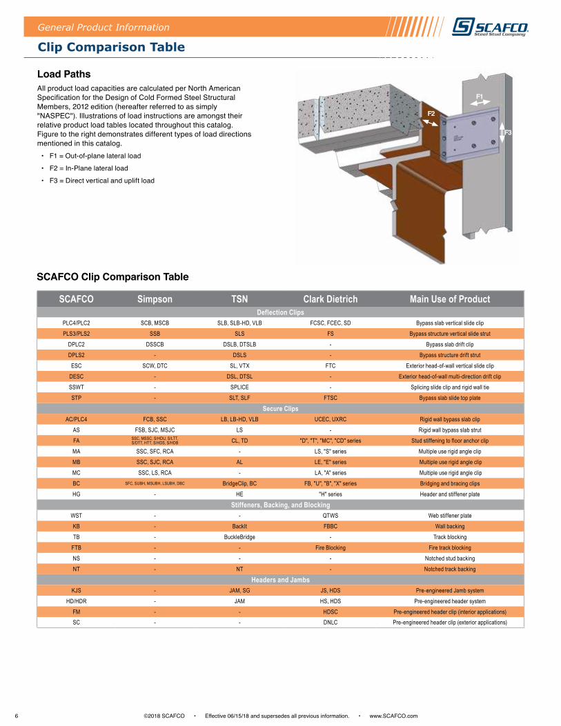
Load Paths All product load capacities are calculated per North American Specification for the Design of Cold Formed Steel Structural Members, 2012 edition (hereafter referred to as simply "NASPEC") . Illustrations of load instructions are amongst their relative product load tables located throughout this catalog . Figure to the right demonstrates different types of load directions mentioned in this catalog .
• F1 = Out-of-plane lateral load
• F2 = In-Plane lateral load
• F3 = Direct vertical and uplift load
F1
F2
F3
SCAFCO Simpson TSN Clark Dietrich Main Use of ProductDeflection Clips
PLC4/PLC2 SCB, MSCB SLB, SLB-HD, VLB FCSC, FCEC, SD Bypass slab vertical slide clip
PLS3/PLS2 SSB SLS FS Bypass structure vertical slide strut
DPLC2 DSSCB DSLB, DTSLB - Bypass slab drift clip
DPLS2 - DSLS - Bypass structure drift strut
ESC SCW, DTC SL, VTX FTC Exterior head-of-wall vertical slide clip
DESC - DSL, DTSL - Exterior head-of-wall multi-direction drift clip
SSWT - SPLICE - Splicing slide clip and rigid wall tie
STP - SLT, SLF FTSC Bypass slab slide top plate
Secure ClipsAC/PLC4 FCB, SSC LB, LB-HD, VLB UCEC, UXRC Rigid wall bypass slab clip
AS FSB, SJC, MSJC LS - Rigid wall bypass slab strut
FA SSC, MSSC, S/HDU, S/LTT, S/DTT, HTT, S/HDS, S/HDB CL, TD "D", "T", "MC", "CD" series Stud stiffening to floor anchor clip
MA SSC, SFC, RCA - LS, "S" series Multiple use rigid angle clip
MB SSC, SJC, RCA AL LE, "E" series Multiple use rigid angle clip
MC SSC, LS, RCA - LA, "A" series Multiple use rigid angle clip
BC SFC, SUBH, MSUBH, LSUBH, DBC BridgeClip, BC FB, "U", "B", "X" series Bridging and bracing clips
HG - HE "H" series Header and stiffener plate
Stiffeners, Backing, and BlockingWST - - QTWS Web stiffener plate
KB - BackIt FBBC Wall backing
TB - BuckleBridge - Track blocking
FTB - - Fire Blocking Fire track blocking
NS - - - Notched stud backing
NT - NT - Notched track backing
Headers and JambsKJS - JAM, SG JS, HDS Pre-engineered Jamb system
HD/HDR - JAM HS, HDS Pre-engineered header system
FM - - HDSC Pre-engineered header clip (interior applications)SC - - DNLC Pre-engineered header clip (exterior applications)
Clip Comparison Table
7©2018 SCAFCO • Effective 06/15/18 and supersedes all previous information . • www .SCAFCO .com
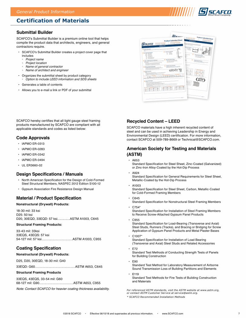
Submittal BuilderSCAFCO’s Submittal Builder is a premium online tool that helps compile the product data that architects, engineers, and general contractors require .
• SCAFCO’s Submittal Builder creates a project cover page that includes ◦ Project name ◦ Project location ◦ Name of general contractor ◦ Name of architect and engineer
• Organizes the submittal sheet by product category ◦ Option to include LEED information and SDS sheets
• Generates a table of contents
• Allows you to e-mail a link or PDF of your submittal
General Product Information
SCAFCO hereby certifies that all light gauge steel framing products manufactured by SCAFCO are compliant with all applicable standards and codes as listed below:
Code Approvals• IAPMO ER-0313
• IAPMO ER-0283
• IAPMO ER-0342
• IAPMO ER-0494
• UL ER3660-02
Design Specifications / Manuals• North American Specification for the Design of Cold-Formed
Steel Structural Members, NASPEC 2012 Edition S100-12
• Gypsum Association Fire Resistance Design Manual
Material / Product SpecificationNonstructural (Drywall) Products:
18-30 mil: 33 ksi D25: 50 ksi D20, 30EQD, 33EQD: 57 ksi…………ASTM A1003, C645
Structural Framing Products:
33-43 mil: 33ksi 33EQS, 43EQS: 57 ksi 54-127 mil: 57 ksi…………………………ASTM A1003, C955
Coating SpecificationNonstructural (Drywall) Products:
D25, D20, 30EQD, 18-30 mil: G40
33EQD: G60…………………………………ASTM A653, C645
Structural Framing Products
33EQS, 43EQS, 33-54 mil: G60 68-127 mil: G90……………………………ASTM A653, C955
Note: Contact SCAFCO for heavier coating thickness availability.
Recycled Content – LEEDSCAFCO materials have a high inherent recycled content of steel and can be used in achieving Leadership in Energy and Environmental Design (LEED) certification . For more information, contact SCAFCO at 509-789-8669 or Technical@SCAFCO .com .
American Society for Testing and Materials (ASTM)
• A653 Standard Specification for Steel Sheet, Zinc-Coated (Galvanized) or Zinc-Iron Alloy-Coated by the Hot-Dip Process
• A924 Standard Specification for General Requirements for Steel Sheet, Metallic-Coated by the Hot-Dip Process
• A1003 Standard Specification for Steel Sheet, Carbon, Metallic-Coated for Cold-Formed Framing Members
• C645 Standard Specification for Nonstructural Steel Framing Members
• C754* Standard Specification for Installation of Steel Framing Members to Receive Screw-Attached Gypsum Panel Products
• C955 Standard Specification for Load-Bearing (Transverse and Axial) Steel Studs, Runners (Tracks), and Bracing or Bridging for Screw Application of Gypsum Panel Products and Metal Plaster Bases
• C1007* Standard Specification for Installation of Load Bearing (Transverse and Axial) Steel Studs and Related Accessories
• E72 Standard Test Methods of Conducting Strength Tests of Panels for Building Construction
• E90 Standard Test Method for Laboratory Measurement of Airborne Sound Transmission Loss of Building Partitions and Elements
• E119 Standard Test Methods for Fire Tests of Building Construction and Materials
For referenced ASTM standards, visit the ASTM website at www.astm.org, or contact ASTM Customer Service at [email protected].* SCAFCO Recommended Installation Methods
Spokane Washington Manufacturing Facility
Stockton California Manufacturing Facility
2800 East Main Avenue, Spokane, WA 99202
2525 South Airport Way, Stockton, CA 95206
Phone: 509.343.9000 Fax: 509-343-9060
Phone: 209.670.8053 Fax: 209.670.8057Product Information
Steel Material Properties54 Mil Labeled Thickness3-5/8" Web Width
0.0566" Design Thickness3-1/2" Flange Height
0.0538" Minimum Thickness1" Return Length
57 ksi Yield Strength (Fy)65 ksi Tensile Strength (Fu)G60 Galvanize Coating ThicknessLEED - Possible Points for Certification
Recycled Content of Steel
ASTM and AISI Code Standards
SCAFCO Technical ServicesSection PropertiesTable Notes:
6. Vax is the allowable shear force parallel to the x-x axi. Vay is the allowable shear force parallel to the y-y axis.Area (in^2) Weight (lb/ft) Ix (in^4)
Rx (in) Iy
(in^4) Ry (in) Iy (in^4)Sy
(in^3)May
(in-k)
0.6912.350
1.2401.340 1.613
1.5281.484 0.671 22.89Distortional
Ix (+) (in^4) Sx (+) (in^3) Max (+) (in-k)Ix (-)
(in^4)Sx (-)
(in^3)Max (-) (in-k) May (in-k)
Vax (lb)
Vay (lb)
1.2060.556 18.980 1.153 0.589
20.12023.17 3600 7200
Clip Alowable LoadsTable Notes:
Vertical Horizontal
362KJS338-54 362FM350-54 44
955485
Product Submittal Sheet362HD350-54The Priceless Headers system is designed cut-to-length and ready to install. This precut assembly will help standardize the installation
process while eliminating labor intensive and expensive conventional methods. With individual section property tables included, this
unique header and jamb system creates simplicity for the architect, engineer, and contractor.
SCAFCO materials have a high inherent recycled content and can be used in achieving
LEED Certification.
• 9.4% Pre-Consumer Scrap Recycled Content• 24.3% Post-Consumer Scrap Recycled Content
Geometric Properties
• LEED Credit MR 2.1 & 2.2: Constr. Waste Mngmgt. (2 Possible Points)
• 34.9% Total Recycled Content
• LEED Credit MR 4.1 & 4.2: Recycled Content (2 Possible Points)
• LEED Credit MR 5.1 & 5.2: Regional Materials (2 Possible Points)
• ASTM A653/A653M, A924/A924M, A1003, C645, C754, C955, C1007
For additional information, visit www.SCAFCO.com or contact technical
services at 509-343-9000 or [email protected]
• AISI NASPEC 2007 Edition S100-07 (Supplement S2-10 for IBC 2012)
• 2012, 2015 International Building Codes and 2010, 2013 CBC
Effective Properties
Shear
1. Effective properties based on the "North american Specification for the Design of Cold-Formed Structural Members"
2. Effective Ixx, Iyy is the Moment of Inertia for delflection based on NASPEC 'Procedure 1'.
3. Allowable Moment (Max and May) of combined sections are based on a non-composite relative stiffness model.
4. Distortional buckling is based on Kf=05. Max-x is for bending about the x-x axis. May-y is for bendig about the y-y axis.
Gross Properties
Effective Properties y-y
1. In the case of varying thickness of header and jamb material, use the lowest of the two corresponding allowable loads listed.
2. For web widths not listed, use the next web width smaller in size(ex. For 4" members use 3.625" values)
3. Maximum gap between end of header member and vertical face of clip shall not exceed 3/8 inch
4. For the 4 fastener connection - screws are to be installed in corner pre-drilled hole locations.
For the 6 fastener connection - screws are to be installed in top and bottom rows of pre-drilled holesFlush Mount Clip Allowable LoadsJambClip
#10 Fasteners from Clip to
Header
#10 Fasterners from Clip to
Jamb
Allowable Sear Load(lbs)
Y
Y
XX
Track strength notincluded in thesection properties
13 / 31
ER 0313
Spokane Washington Manufacturing Facility Stockton California Manufacturing Facility
2800 East Main Avenue, Spokane, WA 99202 2525 South Airport Way, Stockton, CA 95206
Phone: 509.343.9000 Fax: 509-343-9060 Phone: 209.670.8053 Fax: 209.670.8057
Product Information
Steel Material PropertiesGeometric Properties
LEED - Possible Points for Certification Recycled Content of Steel
ASTM and AISI Code StandardsSCAFCO Technical Services
Section PropertiesTable Notes:
Area(in2)
Weight(lb/ft)
Ix(in4)
Sx(in3)
Rx(in)
Iy(in4)
Ry(in)
Ixe(in4)
Sxe(in3)
Mal(in-k)
Mad(in-k)
Vag(lb)
VaNet(lb)
Jx1000(in4)
Cw(in6)
Xo(in)
m(in)
Ro(in)
ß
0.556 1.89 2.860 0.953 2.267 0.180 0.570 2.860 0.916 30.33 25.90 2823 1947 0.594 1.337 -1.049 0.663 2.562 0.832 31.4
Limiting Wall HeightsTable Notes:
1. Listed wind pressures represent calculated designed wind pressure (1.0 W based on 2009 or 0.6 W based on 2012 IBC). For deflection calculations, listed wind pressures have been reduced
by 0.70 as allowed by IBC. The 5 psf pressure has not been reduced for deflection checks.
3. Studs are assumed to be adequately braced at a maximum spacing of Lu to develop full allowable moment.
Product Submittal Sheet
600S162-54
The structural stud is fabricated from prime mill certified steel with a true galvanized coating. Heavier coatings may be available upon
request.
54 Mil Labeled Thickness6" Web Width
0.0566" Design Thickness1-5/8" Flange Height
0.0538" Minimum Thickness1/2" Return Length
50 ksi Yield Strength (Fy)
65 ksi Tensile Strength (Fu)
G60 Galvanize Coating Thickness
• 2012, 2015 International Building Codes and 2010, 2013 CBC
Green Color Code (Painted Ends)
SCAFCO materials have a high inherent recycled content and can be used in achieving
LEED Certification.
• 9.4% Pre-Consumer Scrap Recycled Content
• 24.3% Post-Consumer Scrap Recycled Content
• LEED Credit MR 2.1 & 2.2: Constr. Waste Management (2 Possible Points) • 34.9% Total Recycled Content
• LEED Credit MR 4.1 & 4.2: Recycled Content (2 Possible Points)
• LEED Credit MR 5.1 & 5.2: Regional Materials (2 Possible Points)
• ASTM A653/A653M, A924/A924M, A1003, C645, C754, C955, C1007 For additional information, visit www.SCAFCO.com or contact
technical services at 509-343-9000 or [email protected]
• AISI S100-07 with supplement S2-10 per 2012 IBC, AISI S100-12 per 2015 IBC
punch-out adjacent to the support.
1. The centerline bend radius is based on inside corner radii.
2. Effective properties incorporate the strength increase from the cold work of forming as applicable per AISI S100 A7.2.
3. Tabulated gross properties are based on the full-unreduced cross section of the studs away from punch-out's.
4. For deflection calculations, use the effective moment of inertia.
5. Allowable moment is the lesser of Mal and Mad. Stud distortional buckling is based on an assumed Kφ = 0.
Section
Gross Properties Effective and Distortional Properties Torsional Properties Lu(in)
600S162-54
2. Studs must be braced against rotation and lateral movement at all supports.
4. Web crippling check is based on 1" of bearing at end supports and 3" of bearing at interior support.
5. Shear and web crippling capacity at end supports have not been reduced for punch-out's. Shear and web crippling capacity at interior support have been reduced for the presence of
L/3604. Combined bending and shear check at interior support is based on unreinforced web per AISI S100 (Eq. C3.3.1-1). Shear capacity and combined bending and shear check at interior
support have been reduced for the presence of punch-out's adjacent to support.
Stud Spacing (in)
Non-Composite Fully Braced (5 psf) Non-Composite Fully Braced (15 psf) Non-Composite Fully Braced (20 psf)
L/120 L/240
L/600
12" o.c. 42' 2" 33' 5" 29' 2"L/360 L/240 L/360 L/600 L/240
15' 6"
16" o.c. 38' 3" 30' 4" 26' 6" 21' 1" 18' 5" 15' 6" 19' 1" 16' 8"20' 3" 17' 1" 21' 1" 18' 5"23' 2"
12' 3"14' 1"
24" o.c. 33' 5" 26' 6" 23' 2" 18' 5" 16' 1" 13' 6" 16' 8" 14' 7"
ESR-3064P
Web
Wid
th
Return
Flange
Y
Y
XX
5 / 31
ER 0313
Certification of Materials

8 ©2018 SCAFCO • Effective 06/15/18 and supersedes all previous information . • www .SCAFCO .com
2 1/4"
0.28"
5 1/2"
5"
5"
5"
5"
3 1/2"
2 1/4"
1 1/8" O.C.
7 1/2"
2 1/4"
2 1/4"
R0.196"
9 1/2" 1 1/8"
PLC4 - Bypass Slab Slide Clip
Product Application The PLC4 bypass clip is a premium option for bypass curtain wall connections. The PLC4’s advanced design provides secure attachment to the main building structure while allowing seamless vertical deflection . The bypass clip has multiple features specifically designed to improve the user experience .
Premium Product• Quicker installation (custom screws)
• Safer material handling (coped corners)
• Increased load capacity
Profile Features The PLC4 Bypass Clip has been engineered to provide the greatest allowable loads in the industry . With input from the contractor, the clip is also designed to be user friendly and save labor . The following features help make this product the leader in the industry:
Movement
• Deflection slots ◦ 2¼" slots (allows for 2" of total deflection) ◦ 3 slots for multiple screw configurations
• Proprietary Screws ◦ Shouldered screws are provided for ease of installation
Strength
• Stiffening lips and ribs ◦ Increased compression strength for high wind loads ◦ Stiffened clip face for ease of installation
• Support gussets ◦ Support gussets for transfer of tension forces from connection
through the supporting structure
Versatility
• Secure attachment ◦ 4 pre-drilled holes for optional secure attachment ◦ One clip for multiple uses to save labor on the job site
• Pre-punched holes ◦ Pre-punched holes for multiple attachment methods to structure
Safety
• Coped corners ◦ Fewer sharp corners for reduced possibility of field injury
Material Composition• Mill certified steel
• ASTM A653/A653M
• Clip ◦ 68 mil material thickness ◦ 57 ksi yield strength ◦ 65 ksi tensile strength ◦ G90 galvanized coating
• Shouldered screw ◦ ASTM C1513 ◦ C1022 case hardened steel ◦ Zinc plated coating ◦ 1000 hours salt spray life ◦ Exceeds standard screw life by over 10X
Deflection ClipsDeflection Clips
PLC4-350
PLC4-550
PLC4-750
PLC4-950
#14 Shouldered Screw(included) IAPMO
UNIFORMER 0 4 9 4
IAPMOUNIFORMER 0 4 9 4

9©2018 SCAFCO • Effective 06/15/18 and supersedes all previous information . • www .SCAFCO .com
Part No. Width Qty / Stack Lbs / Stack
PLC4-350 3 ½" 35 19
PLC4-550 5 ½" 35 26
PLC4-750 7 ½" 35 34
PLC4-950 9 ½" 25 30
All PLC4 clips include shouldered screws . Additional lengths available upon request .
Quantity / Order Information
Part No.
Allowable Loads (lbs) F1/F2-Direction (See Illustration) Stud Properties 2 #14 Screws 3 #14 Screws
Thickness (mil) Gauge Fy (ksi) F1 (lbs) F2 (lbs) F1 (lbs) F2 (lbs)
PLC4550750950
33EQS 20 57 485 510 738 784
33 20 33 485 510 738 784
43EQS 18 57 601 621 950 1006
43 18 33 601 621 950 1006
54 16 50 928 935 1367 1411
68 14 50 1242 1086 1480 1986
97 12 50 1242 1086 1480 1986
118 10 50 1242 1086 1480 1986
Maximum Allowable Clip Capacity - Max F2 = 1986 lbs (Compression)
Part No.
Allowable Loads (lbs) F1/F2-Direction (See Illustration)Stud Properties 2 #14 Screws
Thickness (mil) Gauge Fy (ksi) F1 (lbs) F2 (lbs)
PLC4350
33EQS 20 57 485 510
33 20 33 485 510
43EQS 18 57 601 621
43 18 33 601 621
54 16 50 928 935
68 14 50 1242 1086
97 12 50 1242 1086
118 10 50 1242 1086
Maximum Allowable Clip Capacity - Max F1 = 1242 lbs (Tension)
Allowable Loads
Table Notes1 . SCAFCO proprietary #14 shouldered screws described in section 3 .2 .2 of IAPMO ER 0494 must be used
for allowable loads .2 . Allowable loads are minimum of ASD allowable loads from testing and 1/8" relative deflection service limit . 3 . Reference figures to the right for load direction: F1 - Loads shown indicate tension force resistance . F2 -
Loads shown indicate compression force resistance . 4 . Number of screws shall be designated by design professional to meet loading conditions .
For SI: 1 mil = 0 .0254 mm, 1 inch = 25 .4 mm, 1 lb = 4 .45N
Deflection Clips
PLC4 - Bypass Slab Slide Clip
Typical PLC4 Installation
Ten .
Com .
F1
F2
IAPMOUNIFORMER 0 4 9 4
IAPMOUNIFORMER 0 4 9 4
Typical Stud Offset from Structure Installation
Ten .
Com .
F1
10 ©2018 SCAFCO • Effective 06/15/18 and supersedes all previous information . • www .SCAFCO .com
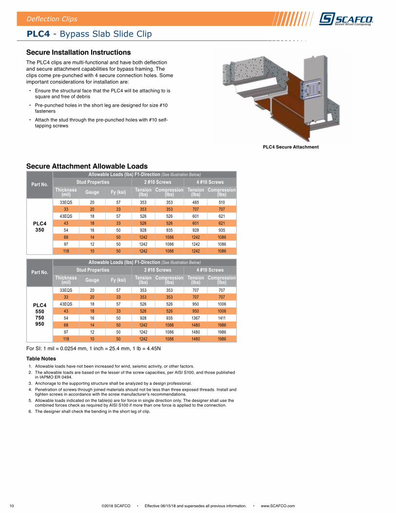
Secure Attachment Allowable Loads
Table Notes1 . Allowable loads have not been increased for wind, seismic activity, or other factors .2 . The allowable loads are based on the lesser of the screw capacities, per AISI S100, and those published
in IAPMO ER 0494 .3 . Anchorage to the supporting structure shall be analyzed by a design professional .4 . Penetration of screws through joined materials should not be less than three exposed threads . Install and
tighten screws in accordance with the screw manufacturer's recommendations .5 . Allowable loads indicated on the table(s) are for force in single direction only . The designer shall use the
combined forces check as required by AISI S100 if more than one force is applied to the connection .6 . The designer shall check the bending in the short leg of clip .
For SI: 1 mil = 0 .0254 mm, 1 inch = 25 .4 mm, 1 lb = 4 .45N
PLC4 Secure Attachment
PLC4 - Bypass Slab Slide Clip
Deflection Clips
Part No.
Allowable Loads (lbs) F1-Direction (See Illustration Below)
Stud Properties 2 #10 Screws 4 #10 ScrewsThickness
(mil) Gauge Fy (ksi) Tension (lbs)
Compression (lbs)
Tension (lbs)
Compression (lbs)
PLC4350
33EQS 20 57 353 353 485 51033 20 33 353 353 707 707
43EQS 18 57 526 526 601 62143 18 33 526 526 601 62154 16 50 928 935 928 93568 14 50 1242 1086 1242 108697 12 50 1242 1086 1242 1086118 10 50 1242 1086 1242 1086
Part No.
Allowable Loads (lbs) F1-Direction (See Illustration Below)
Stud Properties 2 #10 Screws 4 #10 ScrewsThickness
(mil) Gauge Fy (ksi) Tension (lbs)
Compression (lbs)
Tension (lbs)
Compression (lbs)
PLC4550750950
33EQS 20 57 353 353 707 70733 20 33 353 353 707 707
43EQS 18 57 526 526 950 100643 18 33 526 526 950 100654 16 50 928 935 1367 141168 14 50 1242 1086 1480 198697 12 50 1242 1086 1480 1986118 10 50 1242 1086 1480 1986
Secure Installation InstructionsThe PLC4 clips are multi-functional and have both deflection and secure attachment capabilities for bypass framing . The clips come pre-punched with 4 secure connection holes . Some important considerations for installation are:
• Ensure the structural face that the PLC4 will be attaching to is square and free of debris
• Pre-punched holes in the short leg are designed for size #10 fasteners
• Attach the stud through the pre-punched holes with #10 self-tapping screws

11©2018 SCAFCO • Effective 06/15/18 and supersedes all previous information . • www .SCAFCO .com
PLC2 - Bypass Slab Slide Clip
Product ApplicationThe PLC2 bypass slab slide clip secures the bypass curtain wall stud to the building structure, allowing for vertical deflection while maintaining lateral rigidity .
The insert is attached to the clip, making installation quick, easy, and efficient . Clips come packaged in durable buckets for convenient handling on the jobsite . Patent No . 7478508-B2 .
Features and Benefits • Insert allows for 1 ½" total vertical deflection
◦ Deflection greater than 1 ½" is available
• Loads based on #12 screw connection ◦ Screws are provided
• Large insert piece for easy installation
• Pre-punched guide holes
• Thicker steel for improved weld capacity to the structure
• Transfers horizontal load into structure
• Maintains lateral rigidity
Material Composition• Mill certified steel
• ASTM A653/A653M
• Clip ◦ 118 mil material thickness ◦ 57 ksi yield strength ◦ 65 ksi tensile strength ◦ G90 galvanized coating
• Insert ◦ 127 mil material thickness ◦ 57 ksi yield strength ◦ 65 ksi tensile strength ◦ G90 galvanized coating
Deflection Clips
Allowable Loads
Quantity / Order Information
Table Notes1 . Allowable loads have not been increased for wind, seismic activity, or other factors .2 . The allowable loads are based on the steel properties of the members being
connected, per AISI S100 .3 . The nominal strength of the screw must be at least 3 .75 times the allowable loads .4 . Penetration of screws through joined materials should not be less than three exposed
threads . Install and tighten screws in accordance with the screw manufacturer's recommendations .
5 . Screw shear capacities are based on allowable strength design (ASD) and include a safety factor of 3 .0 .
6 . Allowable loads indicated on the table(s) are for force in single direction only . The designer shall use the combined forces check as required by AISI S100 if more than one force is applied to the connection .
7 . The designer shall check the bending in the short leg of the clip .
F1
Part No. Width Qty / Bucket Lbs / Bucket
PLC2-550 5 ½" 30 54PLC2-750 7 ½" 25 54PLC2-950 9 ½" 20 50PLC2-1150 11 ½" 20 57
All PLC2 clips include insert. Additional lengths available upon request.
Part No. Stud Properties F1 Allowable Loads (lbs)Mil Gauge Fy (ksi) 2 #12 Screws 3 #12 Screws
PLC2550 750
33EQS 20 57 429 64333 20 33 377 565
43EQS 18 57 677 101543 18 33 561 84154 16 50 1139 170968 14 50 1610 197597 12 50 1975 1975118 10 50 1975 1975
Maximum Allowable Clip Capacity Max F1 = 1975 lbs
Part No. Stud Properties F1 Allowable Loads (lbs)Mil Gauge Fy (ksi) 2 #12 Screws 3 #12 Screws
PLC2950 1150
33EQS 20 57 429 64333 20 33 377 565
43EQS 18 57 677 101543 18 33 561 84154 16 50 1139 165068 14 50 1650 165097 12 50 1650 1650118 10 50 1650 1650
Maximum Allowable Clip Capacity Max F1 = 1650 lbs
5 ½"
Width
1 ½"Deflection

12 ©2018 SCAFCO • Effective 06/15/18 and supersedes all previous information . • www .SCAFCO .com
PLS3 - Bypass Slab Slide Strut
Product ApplicationThe PLS3 bypass slab slide strut secures the bypass curtain wall stud to the building structure, allowing for vertical deflection while maintaining lateral rigidity . The strut provides a non-frictional connection and prevents vertical load transfer into the curtain wall .
The insert is attached to the strut, making installation quick, easy, and efficient . Struts 12" in length or less come packaged in durable buckets for convenient handling on the jobsite .
Features and Benefits • Insert allows for 2" total vertical deflection
◦ Deflection of 1" up and 1" down
• Loads based on #12 screw connection ◦ Screws are provided
• Large insert piece for easy installation
• Pre-punched guide holes
• Transfers horizontal load into structure
• Maintains lateral rigidity
Material Composition• Mill certified steel
• ASTM A653/A653M
• Clip ◦ 68 mil material thickness ◦ 57 ksi yield strength ◦ 65 ksi tensile strength ◦ G90 galvanized coating
• Insert ◦ 86 mil material thickness ◦ 57 ksi yield strength ◦ 65 ksi tensile strength ◦ G90 galvanized coating
Deflection Clips
Part No. Left / Right Handed Width Qty / Bucket Lbs / Bucket
PLS3-900 Universal 9" 35 54PLS3-1200 Universal 12" 30 59PLS3-1500 Universal 15" - -PLS3-1800 Universal 18" - -PLS3-2000 Universal 20" - -
Part No. Stud Properties F1 Allowable Loads (lbs) Mil Gauge Fy (ksi) 2 #12 Screws 3 #12 Screws
PLS3
33EQS 20 57 429 64333 20 33 377 565
43EQS 18 57 677 101543 18 33 561 84154 16 50 1139 170968 14 50 1610 218097 12 50 2180 2180118 10 50 2180 2180
Maximum Allowable Clip Capacity Max F1 = 2180 lbs
Allowable Loads
Quantity / Order Information
Table Notes1 . Allowable loads have not been increased for wind, seismic activity, or other factors .2 . The allowable loads are based on the steel properties of the members being connected,
per AISI S100 .3 . The nominal strength of the screw must be at least 3 .75 times the allowable loads .4 . Penetration of screws through joined materials should not be less than three exposed
threads . Install and tighten screws in accordance with the screw manufacturer's recommendations .
5 . Screw shear capacities are based on allowable strength design (ASD) and include a safety factor of 3 .0 .
6 . Allowable loads indicated on the table(s) are for force in single direction only . The designer shall use the combined forces check as required by AISI S100 if more than one force is applied to the connection .
7 . The designer shall check the bending in the short leg of the clip .
F1
All PLS3 struts include insert. Additional lengths available upon request. Stiffening lip added for struts 20" in length and over.
6"
Width
2"Deflection

13©2018 SCAFCO • Effective 06/15/18 and supersedes all previous information . • www .SCAFCO .com
PLS2 - Bypass Slab Slide Strut
Product ApplicationThe PLS2 bypass slab slide strut secures the bypass curtain wall stud to the building structure, allowing for vertical deflection while maintaining lateral rigidity . The strut provides a non-frictional connection and prevents vertical load transfer into the curtain wall .
The insert is attached to the clip, making installation quick, easy, and efficient . Patent No . 7478508-B2
Features and Benefits • Insert allows for 1 ½" total vertical deflection
◦ Deflection greater than 1 ½" is available
• Loads based on #12 screws ◦ Screws are provided
• Large insert piece for easy installation
• Pre-punched guide holes
• Thicker steel for improved weld capacity to the structure
• Transfers horizontal load into structure
• Maintains lateral rigidity
Material Composition• Mill certified steel
• ASTM A653/A653M
• Clip ◦ 118 mil material thickness ◦ 57 ksi yield strength ◦ 65 ksi tensile strength ◦ G90 galvanized coating
• Insert ◦ 127 mil material thickness ◦ 57 ksi yield strength ◦ 65 ksi tensile strength ◦ G90 galvanized coating
Deflection Clips
Allowable Loads
Quantity / Order Information
Table Notes1 . Allowable loads have not been increased for wind, seismic activity, or other factors .2 . The allowable loads are based on the steel properties of the members being connected,
per AISI S100 .3 . The nominal strength of the screw must be at least 3 .75 times the allowable loads .4 . Penetration of screws through joined materials should not be less than three exposed
threads . Install and tighten screws in accordance with the screw manufacturer's recommendations .
5 . Screw shear capacities are based on allowable strength design (ASD) and include a safety factor of 3 .0 .
6 . Allowable loads indicated on the table(s) are for force in single direction only . The designer shall use the combined forces check as required by AISI S100 if more than one force is applied to the connection .
7 . The designer shall check the bending in the short leg of clip .
F1
Part No. Left / Right Handed Width Qty / Bucket Lbs / Bucket
PLS2-900 (L) or (R) 9" 20 53PLS2-1200 (L) or (R) 12" 15 51PLS2-1500 (L) or (R) 15" - -PLS2-1800 (L) or (R) 18" - -PLS2-2000 (L) or (R) 20" - -
All PLS2 struts include insert. Additional lengths available upon request.Stiffening lip added for struts 20" in length and over.
Part No. Stud Properties F1 Allowable Loads (lbs) Mil Gauge Fy (ksi) 2 #12 Screws 3 #12 Screws
PLS2
33EQS 20 57 429 64333 20 33 377 565
43EQS 18 57 677 101543 18 33 561 84154 16 50 1139 170968 14 50 1610 227597 12 50 2275 2275118 10 50 2275 2275
Maximum Allowable Clip Capacity Max F1 = 2275 lbs
*PLS2: Shown as Right Handed Strut .
*PLS2: Shown as Right Handed Strut .
5 ½"
Width
1 ½"Deflection
14 ©2018 SCAFCO • Effective 06/15/18 and supersedes all previous information . • www .SCAFCO .com
DPLC2 - Bypass Slab Drift Clip
Deflection Clips
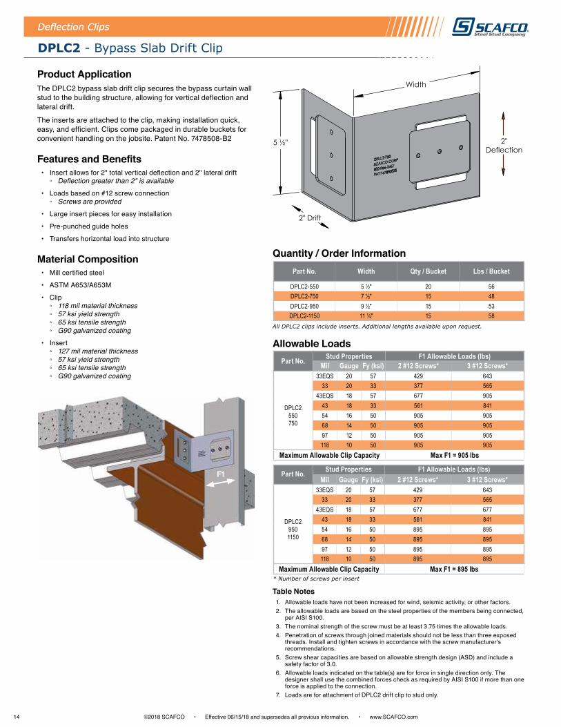
Product ApplicationThe DPLC2 bypass slab drift clip secures the bypass curtain wall stud to the building structure, allowing for vertical deflection and lateral drift .
The inserts are attached to the clip, making installation quick, easy, and efficient . Clips come packaged in durable buckets for convenient handling on the jobsite . Patent No . 7478508-B2
Features and Benefits • Insert allows for 2" total vertical deflection and 2" lateral drift
◦ Deflection greater than 2" is available
• Loads based on #12 screw connection ◦ Screws are provided
• Large insert pieces for easy installation
• Pre-punched guide holes
• Transfers horizontal load into structure
Material Composition• Mill certified steel
• ASTM A653/A653M
• Clip ◦ 118 mil material thickness ◦ 57 ksi yield strength ◦ 65 ksi tensile strength ◦ G90 galvanized coating
• Insert ◦ 127 mil material thickness ◦ 57 ksi yield strength ◦ 65 ksi tensile strength ◦ G90 galvanized coating
Deflection Clips
F1
Allowable Loads
Quantity / Order Information
Table Notes1 . Allowable loads have not been increased for wind, seismic activity, or other factors .2 . The allowable loads are based on the steel properties of the members being connected,
per AISI S100 .3 . The nominal strength of the screw must be at least 3 .75 times the allowable loads .4 . Penetration of screws through joined materials should not be less than three exposed
threads . Install and tighten screws in accordance with the screw manufacturer's recommendations .
5 . Screw shear capacities are based on allowable strength design (ASD) and include a safety factor of 3 .0 .
6 . Allowable loads indicated on the table(s) are for force in single direction only . The designer shall use the combined forces check as required by AISI S100 if more than one force is applied to the connection .
7 . Loads are for attachment of DPLC2 drift clip to stud only .
All DPLC2 clips include inserts. Additional lengths available upon request.
Part No. Width Qty / Bucket Lbs / Bucket
DPLC2-550 5 ½" 20 56DPLC2-750 7 ½" 15 48DPLC2-950 9 ½" 15 53DPLC2-1150 11 ½" 15 58
Part No. Stud Properties F1 Allowable Loads (lbs)Mil Gauge Fy (ksi) 2 #12 Screws* 3 #12 Screws*
33EQS 20 57 429 64333 20 33 377 565
DPLC2550 750
43EQS 18 57 677 90543 18 33 561 84154 16 50 905 90568 14 50 905 90597 12 50 905 905118 10 50 905 905
Maximum Allowable Clip Capacity Max F1 = 905 lbs
Part No. Stud Properties F1 Allowable Loads (lbs)Mil Gauge Fy (ksi) 2 #12 Screws* 3 #12 Screws*
33EQS 20 57 429 64333 20 33 377 565
DPLC2950 1150
43EQS 18 57 677 67743 18 33 561 84154 16 50 895 89568 14 50 895 89597 12 50 895 895118 10 50 895 895
Maximum Allowable Clip Capacity Max F1 = 895 lbs* Number of screws per insert
5 ½"
Width
2" Drift
2"Deflection
15©2018 SCAFCO • Effective 06/15/18 and supersedes all previous information . • www .SCAFCO .com
Deflection Clips
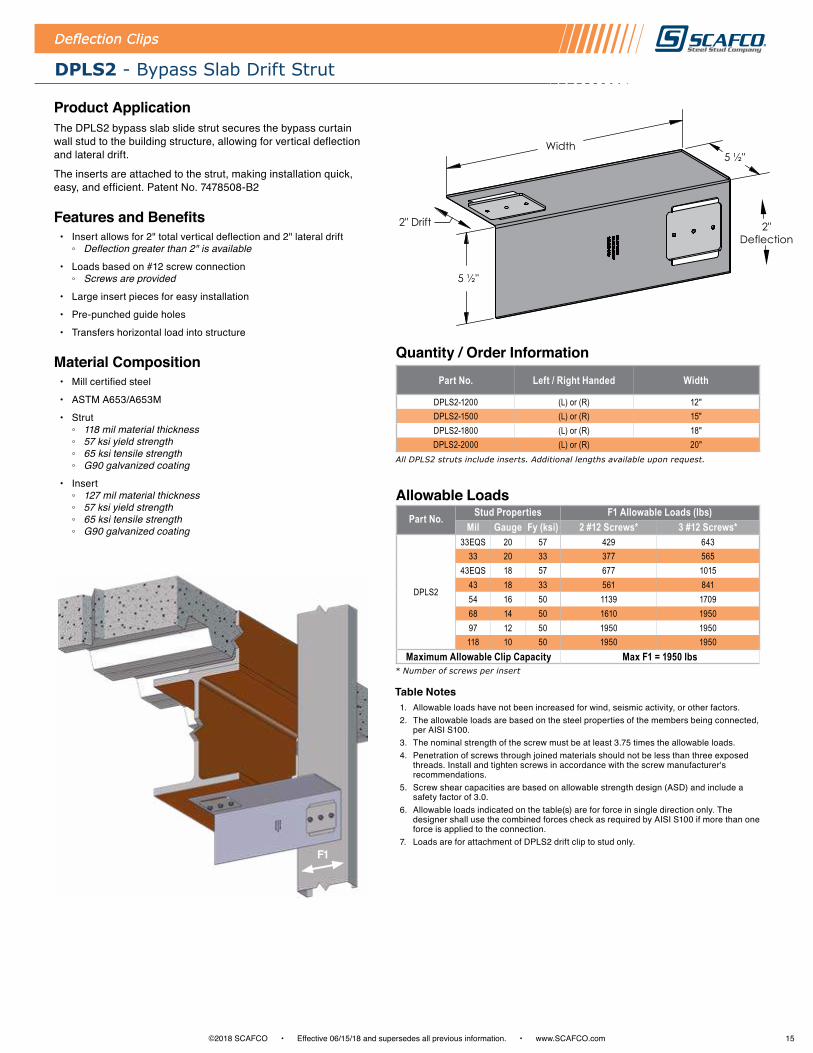
DPLS2 - Bypass Slab Drift Strut
Product ApplicationThe DPLS2 bypass slab slide strut secures the bypass curtain wall stud to the building structure, allowing for vertical deflection and lateral drift .
The inserts are attached to the strut, making installation quick, easy, and efficient . Patent No . 7478508-B2
Features and Benefits • Insert allows for 2" total vertical deflection and 2" lateral drift
◦ Deflection greater than 2" is available
• Loads based on #12 screw connection ◦ Screws are provided
• Large insert pieces for easy installation
• Pre-punched guide holes
• Transfers horizontal load into structure
Material Composition• Mill certified steel
• ASTM A653/A653M
• Strut ◦ 118 mil material thickness ◦ 57 ksi yield strength ◦ 65 ksi tensile strength ◦ G90 galvanized coating
• Insert ◦ 127 mil material thickness ◦ 57 ksi yield strength ◦ 65 ksi tensile strength ◦ G90 galvanized coating
Deflection Clips
Allowable Loads
Quantity / Order Information
Table Notes1 . Allowable loads have not been increased for wind, seismic activity, or other factors .2 . The allowable loads are based on the steel properties of the members being connected,
per AISI S100 .3 . The nominal strength of the screw must be at least 3 .75 times the allowable loads .4 . Penetration of screws through joined materials should not be less than three exposed
threads . Install and tighten screws in accordance with the screw manufacturer's recommendations .
5 . Screw shear capacities are based on allowable strength design (ASD) and include a safety factor of 3 .0 .
6 . Allowable loads indicated on the table(s) are for force in single direction only . The designer shall use the combined forces check as required by AISI S100 if more than one force is applied to the connection .
7 . Loads are for attachment of DPLS2 drift clip to stud only .F1
Part No. Left / Right Handed Width
DPLS2-1200 (L) or (R) 12"DPLS2-1500 (L) or (R) 15"DPLS2-1800 (L) or (R) 18"DPLS2-2000 (L) or (R) 20"
All DPLS2 struts include inserts. Additional lengths available upon request.
Part No. Stud Properties F1 Allowable Loads (lbs)Mil Gauge Fy (ksi) 2 #12 Screws* 3 #12 Screws*
DPLS2
33EQS 20 57 429 64333 20 33 377 565
43EQS 18 57 677 101543 18 33 561 84154 16 50 1139 170968 14 50 1610 195097 12 50 1950 1950118 10 50 1950 1950
Maximum Allowable Clip Capacity Max F1 = 1950 lbs* Number of screws per insert
5 ½"
Width
2" Drift
5 ½"
2"Deflection
16 ©2018 SCAFCO • Effective 06/15/18 and supersedes all previous information . • www .SCAFCO .com
Allowable Loads
Quantity / Order Information
Table Notes1 . Allowable loads have not been increased for wind, seismic activity, or other factors .2 . The allowable loads are based on the steel properties of the members being connected,
per AISI S100 .3 . The nominal strength of the screw must be at least 3 .75 times the allowable loads .4 . Penetration of screws through joined materials should not be less than three exposed
threads . Install and tighten screws in accordance with the screw manufacturer's recommendations .
5 . Screw shear capacities are based on allowable strength design (ASD) and include a safety factor of 3 .0 .
6 . Allowable loads indicated on the table(s) are for force in single direction only . The designer shall use the combined forces check as required by AISI S100 if more than one force is applied to the connection .
7 . The designer shall check the bending in the short leg of the clip .
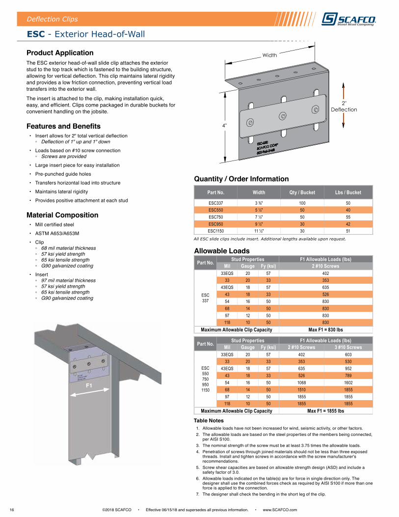
ESC - Exterior Head-of-Wall
Product ApplicationThe ESC exterior head-of-wall slide clip attaches the exterior stud to the top track which is fastened to the building structure, allowing for vertical deflection . This clip maintains lateral rigidity and provides a low friction connection, preventing vertical load transfers into the exterior wall .
The insert is attached to the clip, making installation quick, easy, and efficient . Clips come packaged in durable buckets for convenient handling on the jobsite .
Features and Benefits • Insert allows for 2" total vertical deflection
◦ Deflection of 1" up and 1" down
• Loads based on #10 screw connection ◦ Screws are provided
• Large insert piece for easy installation
• Pre-punched guide holes
• Transfers horizontal load into structure
• Maintains lateral rigidity
• Provides positive attachment at each stud
Material Composition• Mill certified steel
• ASTM A653/A653M
• Clip ◦ 68 mil material thickness ◦ 57 ksi yield strength ◦ 65 ksi tensile strength ◦ G90 galvanized coating
• Insert ◦ 97 mil material thickness ◦ 57 ksi yield strength ◦ 65 ksi tensile strength ◦ G90 galvanized coating
Deflection Clips
Part No. Width Qty / Bucket Lbs / Bucket
ESC337 3 ⅜" 100 50ESC550 5 ½" 50 40ESC750 7 ½" 50 55ESC950 9 ½" 30 42ESC1150 11 ½" 30 51
All ESC slide clips include insert. Additional lengths available upon request.
Part No. Stud Properties F1 Allowable Loads (lbs)Mil Gauge Fy (ksi) 2 #10 Screws 3 #10 Screws
ESC550 750 950 1150
33EQS 20 57 402 60333 20 33 353 530
43EQS 18 57 635 95243 18 33 526 78954 16 50 1068 160268 14 50 1510 185597 12 50 1855 1855118 10 50 1855 1855
Maximum Allowable Clip Capacity Max F1 = 1855 lbs
Part No. Stud Properties F1 Allowable Loads (lbs)Mil Gauge Fy (ksi) 2 #10 Screws
ESC337
33EQS 20 57 40233 20 33 353
43EQS 18 57 63543 18 33 52654 16 50 83068 14 50 83097 12 50 830118 10 50 830
Maximum Allowable Clip Capacity Max F1 = 830 lbs
F1
Width
2"Deflection
4"
17©2018 SCAFCO • Effective 06/15/18 and supersedes all previous information . • www .SCAFCO .com
Allowable Loads
Quantity / Order Information
Table Notes1 . Allowable loads have not been increased for wind, seismic activity, or other factors .2 . The allowable loads are based on the steel properties of the members being connected,
per AISI S100 .3 . The nominal strength of the screw must be at least 3 .75 times the allowable load .4 . Penetration of screws through joined materials should not be less than three exposed
threads . Install and tighten screws in accordance with the screw manufacturer's recommendations .
5 . Screw shear capacities are based on allowable strength design (ASD) and include a safety factor of 3 .0 .
6 . Allowable loads indicated on the table(s) are for force in single direction only . The designer shall use the combined forces check as required by AISI S100 if more than one force is applied to the connection .
7 . The designer shall check the bending in the structural attachment leg of the clip .
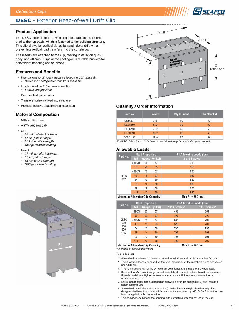
DESC - Exterior Head-of-Wall Drift Clip
Product ApplicationThe DESC exterior head-of-wall drift clip attaches the exterior stud to the top track, which is fastened to the building structure . This clip allows for vertical deflection and lateral drift while preventing vertical load transfers into the curtain wall .
The inserts are attached to the clip, making installation quick, easy, and efficient . Clips come packaged in durable buckets for convenient handling on the jobsite .
Features and Benefits • Insert allows for 2" total vertical deflection and 2" lateral drift
◦ Deflection / drift greater than 2" is available
• Loads based on #10 screw connection ◦ Screws are provided
• Pre-punched guide holes
• Transfers horizontal load into structure
• Provides positive attachment at each stud
Material Composition• Mill certified steel
• ASTM A653/A653M
• Clip ◦ 68 mil material thickness ◦ 57 ksi yield strength ◦ 65 ksi tensile strength ◦ G90 galvanized coating
• Insert ◦ 97 mil material thickness ◦ 57 ksi yield strength ◦ 65 ksi tensile strength ◦ G90 galvanized coating
Deflection Clips
Part No. Stud Properties F1 Allowable Loads (lbs)Mil Gauge Fy (ksi) 2 #10 Screws* 3 #10 Screws*
DESC550 750 950 1150
33EQS 20 57 402 60333 20 33 353 530
43EQS 18 57 635 79543 18 33 526 78954 16 50 795 79568 14 50 795 79597 12 50 795 795118 10 50 795 795
Maximum Allowable Clip Capacity Max F1 = 795 lbs* Number of screws per insert
Part No. Stud Properties F1 Allowable Loads (lbs)Mil Gauge Fy (ksi) 2 #10 Screws*
DESC337
33EQS 20 57 40233 20 33 353
43EQS 18 57 63543 18 33 52654 16 50 83068 14 50 83097 12 50 830118 10 50 830
Maximum Allowable Clip Capacity Max F1 = 380 lbs
Part No. Width Qty / Bucket Lbs / Bucket
DESC337 3 ⅜" 50 40DESC550 5 ½" 30 39DESC750 7 ½" 30 53DESC950 9 ½" 20 45DESC1150 11 ½" 20 54
All DESC slide clips include inserts. Additional lengths available upon request.
F1
4"
4"
Width
2"Deflection
2" Drift

18 ©2018 SCAFCO • Effective 06/15/18 and supersedes all previous information . • www .SCAFCO .com
Deflection Clips
SSWT - Splicing Slide Clip and Rigid Wall Tie
Product ApplicationThe SSWT splicing slide clip and rigid wall tie attach the bypass curtain wall stud to the building structure . This allows for vertical deflection while securely connecting another wall stud .
The insert is attached to the clip, making installation quick, easy, and efficient . Clips come packaged in durable buckets for convenient handling on the jobsite .
Features and Benefits • Unique insert allows for 2" total vertical deflection
◦ Deflection of 1" up and 1" down
• Pre-punched holes for #10 framing screws ◦ Screws are provided
• Maintains lateral rigidity
Material Composition• Mill certified steel
• ASTM A653/A653M
• Clip ◦ 68 mil material thickness ◦ 57 ksi yield strength ◦ 65 ksi tensile strength ◦ G90 galvanized coating
• Insert ◦ 97 mil material thickness ◦ 57 ksi yield strength ◦ 65 ksi tensile strength ◦ G90 galvanized coating
Allowable Loads
Quantity / Order Information
Table Notes1 . Allowable loads have not been increased for wind, seismic activity, or other factors .2 . The allowable loads are based on the steel properties of the members being connected,
per AISI S100 .3 . The nominal strength of the screw must be at least 3 .75 times the allowable load .4 . Penetration of screws through joined materials should not be less than three exposed
threads . Install and tighten screws in accordance with the screw manufacturer's recommendations .
5 . Screw shear capacities are based on allowable strength design (ASD) and include a safety factor of 3 .0 .
6 . Allowable loads indicated on the table(s) are for force in single direction only . The designer shall use the combined forces check as required by AISI S100 if more than one force is applied to the connection .
7 . The designer shall check the bending in the short leg of the clip .
All SSWT slide clips include inserts. Additional lengths available upon request.
Part No. Left / Right Handed Width Qty / Bucket Lbs / Bucket
SSWT-600 (L) or (R) 6" 25 42SSWT-800 (L) or (R) 8" 25 54SSWT-1000 (L) or (R) 10" 20 52
Part No.Stud Properties F1 Allowable Loads (lbs)
Mil Gauge Fy (ksi) 3 #10 Screws* 3 #10 Screws
(6) #10 Screws* 3 #10 Screws
SSWT
33EQS 20 57 603 60333 20 33 530 530
43EQS 18 57 952 95243 18 33 789 78954 16 50 1378 137868 14 50 1378 137897 12 50 1378 1378118 10 50 1378 1378
Maximum Allowable Clip Capacity Max F1 = 1378 lbs
Part No. Stud Properties F3 Allowable Loads (lbs) for Upper HalfMil Gauge Fy (ksi) 3 #10 Screws 6 #10 Screws
SSWT
33EQS 20 57 603 120633 20 33 530 1060
43EQS 18 57 952 190443 18 33 789 157854 16 50 1602 235068 14 50 2266 235097 12 50 2350 2350118 10 50 2350 2350
Maximum Allowable Clip Capacity Max F3 = 2350 lbs* Upper half screw quantity listed first.
F1
10"
Width
2"Deflection

19©2018 SCAFCO • Effective 06/15/18 and supersedes all previous information . • www .SCAFCO .com
STP - Bypass Slab Top Plate
Deflection Clips
Allowable Loads
Quantity / Order Information
Table Notes1 . Allowable loads have not been increased for wind, seismic activity, or other factors .2 . The allowable loads are based on the steel properties of the members being connected,
per AISI S100 .3 . The nominal strength of the screw must be at least 3 .75 times the allowable load .4 . Penetration of screws through joined materials should not be less than three exposed
threads . Install and tighten screws in accordance with the screw manufacturer's recommendations .
5 . Screw shear capacities are based on allowable strength design (ASD) and include a safety factor of 3 .0 .
6 . Allowable loads indicated on the table(s) are for force in single direction only . The designer shall use the combined forces check as required by AISI S100 if more than one force is applied to the connection .
7 . The designer shall check the bending in the structural attachment leg of the clip .
Product ApplicationThe STP bypass slab top plate attaches the bypass curtain wall stud to the building structure, allowing for vertical deflection while maintaining lateral rigidity . This slide strut provides a non-frictional connection and prevents vertical load transfers into the curtain wall .
The insert is attached to the clip, making installation quick, easy, and efficient .
Features and Benefits • Unique insert allows for 2" total vertical deflection
◦ Deflection of 1" up and 1" down
• Pre-punched holes for #12 framing screws
• Maintains lateral rigidity
Material Composition• Mill certified steel
• ASTM A653/A653M
• Clip ◦ 118 mil material thickness ◦ 57 ksi yield strength ◦ 65 ksi tensile strength ◦ G90 galvanized coating
• Insert ◦ 127 mil material thickness ◦ 57 ksi yield strength ◦ 65 ksi tensile strength ◦ G90 galvanized coating
* Number of screws per insert
Part No. Width
STP-900 9"STP-1200 12"STP-1500 15"STP-1800 18"STP-2000 20"
All STP struts include inserts. Additional lengths available upon request.
Part No. Stud Properties F1 Allowable Loads (lbs)Mil Gauge Fy (ksi) 2 #12 Screws*
STP900 1200 1500
33EQS 20 57 71033 20 33 710
43EQS 18 57 71043 18 33 71054 16 50 71068 14 50 71097 12 50 710118 10 50 710
Maximum Allowable Clip Capacity Max F1 = 710 lbs
Part No. Stud Properties F1 Allowable Loads (lbs)Mil Gauge Fy (ksi) 2 #12 Screws*
STP1800 2000
33EQS 20 57 67033 20 33 670
43EQS 18 57 67043 18 33 67054 16 50 67068 14 50 67097 12 50 670118 10 50 670
Maximum Allowable Clip Capacity Max F1 = 670 lbsF1
5" 3 ½"
Width
2"Deflection
2"Deflection
2 1/2"

20 ©2018 SCAFCO • Effective 06/15/18 and supersedes all previous information . • www .SCAFCO .com
Deflection Clips
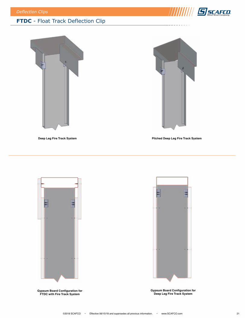
FTDC - Float Track Deflection Clip
Part No. Qty / Bucket Lbs / Bucket
FTDC - 33 250 15FTDC - 43 250 18FTDC - 54 230 22
Quantity / Order Information
Product ApplicationThe FTDC float track deflection clip attaches to the inside flange(s) of the ceiling track . These clips can be utilized to accommodate various track depths for different deflection needs, reinforcing stud-to-track connections without interfering with deflection .
FTDC clips can be used with any stud, gauge, or size of track .
Features and Benefits • Available in three thicknesses: 33mil, 43mil, and 54mil
• Attaches with #10 screws
• Maintains lateral rigidity through positive screw connection
• Packaged in durable buckets for convenient jobsite handling
Material Composition• Mill certified steel
• ASTM A653/A653M
• 33 mil ◦ 33 ksi yield strength ◦ 45 ksi tensile strength ◦ G60 galvanized coating
• 43 mil ◦ 33 ksi yield strength ◦ 45 ksi tensile strength ◦ G60 galvanized coating
• 54 mil ◦ 57 ksi yield strength ◦ 65 ksi tensile strength ◦ G60 galvanized coating
Deep Leg Deflection Track
1 ½"
2 ⅛"
1 ½"
.712"
21©2018 SCAFCO • Effective 06/15/18 and supersedes all previous information . • www .SCAFCO .com
FTDC - Float Track Deflection Clip
Deflection Clips
Deep Leg Fire Track System Pitched Deep Leg Fire Track System
Gypsum Board Configuration for Deep Leg Fire Track System
Gypsum Board Configuration for FTDC with Fire Track System

22 ©2018 SCAFCO • Effective 06/15/18 and supersedes all previous information . • www .SCAFCO .com
Secure Clips
AC - Bypass Slab Secure Clip
Product ApplicationThe AC bypass slab secure clip connects an exterior wall stud to the building structure . Depending on the material properties of the structure and the proposed design, the AC secure clip may be attached to the structure with either an approved fastener or a weld .
AC secure clips are designed to resist horizontal and vertical loads . Clips come packaged in durable buckets for convenient handling on the jobsite .
Features and Benefits • Variety of lengths available
• Ribbed legs for additional strength
• Loads based on #10 screws ◦ Screws are provided
• Pre-punched guide holes
• Transfers horizontal load into structure
• Maintains lateral rigidity
Material Composition• Mill certified steel
• ASTM A653/A653M
• 68 mil ◦ 57 ksi yield strength ◦ 65 ksi tensile strength ◦ G90 galvanized coating
Screw Pattern ConfigurationsNot all detailed screw locations have pre-punched holes . Please refer to clip drawing for pre-punched hole configurations .
Quantity / Order InformationPart No. Width Qty / Bucket Lbs / Bucket
AC250 2 ½" 50 23AC350 3 ½" 50 29AC550 5 ½" 50 41AC750 7 ½" 50 52AC950 9 ½" 35 45
2 Screws 3 Screws 4 Screws2 Screws 4 Screws 6 Screws 8 Screws
8 Screws
AC250, AC350, and AC550 AC750
AC750 with 2" offset AC950 with 2" offset
6 Screws 6 Screws
8 Screws
4 Screws 4 Screws
2 ¾" ¾" 2 ¾" ¾"
2 ¾" ¾"2 ¾"
1"4 2/3" 1"2 1/3" 2 1/3"
2 1/3" 2 1/3" 1"
F1
F3
Secure Clips
6"
Width

23©2018 SCAFCO • Effective 06/15/18 and supersedes all previous information . • www .SCAFCO .com
AC - Bypass Slab Secure Clip Allowable Loads
Secure Clips
Part No. Stud Properties F1 Allowable Loads (lbs) F3 Allowable Loads (lbs)Mil Gauge Fy (ksi) 2 #10 Screws 3 #10 Screws 4 #10 Screws 2 #10 Screws 3 #10 Screws 4 #10 Screws
AC250 350 550
33EQS 20 57 402 603 804 402 603 80433 20 33 353 530 707 353 530 707
43EQS 18 57 635 952 1269 635 952 126943 18 33 526 789 1052 526 789 105254 16 50 1068 1602 1940 1068 1602 194068 14 50 1510 1940 1940 1510 1940 194097 12 50 1585 1940 1940 1940 1940 1940118 10 50 1585 1940 1940 1940 1940 1940
Maximum Allowable Clip Capacity Max F1 = 1940 lbs Max F3 = 1940 lbs
Part No. Stud Properties F1 Allowable Loads (lbs) F3 Allowable Loads (lbs)Mil Gauge Fy (ksi) 4 #10 Screws 6 #10 Screws 8 #10 Screws 4 #10 Screws 6 #10 Screws 8 #10 Screws
AC 750
33EQS 20 57 804 1206 1608 804 1206 160833 20 33 707 1060 1414 707 1060 1414
43EQS 18 57 1269 1903 1940 1269 1903 194043 18 33 1052 1578 1940 1052 1578 194054 16 50 1940 1940 1940 1940 1940 194068 14 50 1940 1940 1940 1940 1940 194097 12 50 1940 1940 1940 1940 1940 1940118 10 50 1940 1940 1940 1940 1940 1940
Maximum Allowable Clip Capacity Max F1 = 1940 lbs Max F3 = 1940 lbs
Part No. Stud Properties F1 Allowable Loads (lbs) F3 Allowable Loads (lbs)Mil Gauge Fy (ksi) 4 #10 Screws 6 #10 Screws 8 #10 Screws 4 #10 Screws 6 #10 Screws 8 #10 Screws
AC750
with 2" offset
33EQS 20 57 804 1206 1550 804 1206 155033 20 33 707 1060 1414 707 1060 1414
43EQS 18 57 1269 1550 1550 1269 1550 155043 18 33 1052 1550 1550 1052 1550 155054 16 50 1550 1550 1550 1550 1550 155068 14 50 1550 1550 1550 1550 1550 155097 12 50 1550 1550 1550 1550 1550 1550118 10 50 1550 1550 1550 1550 1550 1550
Maximum Allowable Clip Capacity Max F1 = 1550 lbs Max F3 = 1550 lbs
Part No. Stud Properties F1 Allowable Loads (lbs) F3 Allowable Loads (lbs)Mil Gauge Fy (ksi) 4 #10 Screws 6 #10 Screws 8 #10 Screws 4 #10 Screws 6 #10 Screws 8 #10 Screws
AC950
with 2" offset
33EQS 20 57 804 1030 1030 804 1030 103033 20 33 707 1030 1030 707 1030 1030
43EQS 18 57 1030 1030 1030 1030 1030 103043 18 33 1030 1030 1030 1030 1030 103054 16 50 1030 1030 1030 1030 1030 103068 14 50 1030 1030 1030 1030 1030 103097 12 50 1030 1030 1030 1030 1030 1030118 10 50 1030 1030 1030 1030 1030 1030
Maximum Allowable Clip Capacity Max F1 = 1030 lbs Max F3 = 1030 lbs
Table Notes 1 . Allowable loads have not been increased for wind, seismic activity, or other factors . 2 . The allowable loads are based on the steel properties of the members being
connected, per AISI S100 .3 . The nominal strength of the screw must be at least 3 .75 times the allowable load .4 . Penetration of screws through joined materials should not be less than three exposed
threads . Install and tighten screws in accordance with the screw manufacturer's recommendations .
5 . Screw shear capacities are based on allowable strength design (ASD) and include a safety factor of 3 .0 .
6 . Allowable loads indicated on the table(s) are for force in single direction only . The designer shall use the combined forces check as required by AISI S100 if more than one force is applied to the connection .
7 . The designer shall check the bending in the short leg of the clip .

24 ©2018 SCAFCO • Effective 06/15/18 and supersedes all previous information . • www .SCAFCO .com
AS - Secure Strut 20" and GreaterArea (in2)
Ixx (in4)
Iyy (in4)
Rx (in)
Ry (in)
Sxx (in3)
Syy (in3)
0.3804 0.4777 0.1270 1.1026 0.5778 0.4215 0.0803
AS - Secure Strut Less Than 20"Area (in2)
Ixx (in4)
Iyy (in4)
Rx (in)
Ry (in)
Sxx (in3)
Syy (in3)
0.3203 0.3392 0.0564 1.029 0.4198 0.3089 0.0461
Section Properties
X X
Y
Y
Part No. Width Qty / Bucket Lbs / Bucket
AS800 8" 50 36AS1000 10" 50 45AS1200 12" 50 54AS1500 15" - -AS2000 20" - -AS2400 24" - -
Quantity / Order Information
Additional lengths available upon request. Strengthening lip added for struts 20" in length and over.
1 ½"
3 ⅛"
< 20"2"
½"
3 ⅛"
≥ 20"
Secure Clips
AS - Load-Bearing Secure Strut
Product ApplicationThe AS load-bearing secure strut is used in various applications, but most commonly to connect an exterior wall stud that bypasses the building structure . Depending on the material properties of the structure and the proposed design, the AS secure strut may be attached to the structure with either an approved fastener or a weld . AS secure struts are designed to resist axial compression tension loads .
Features and Benefits • Variety of lengths available
• Transfers horizontal load into structure
• Maintains lateral rigidity
Material Composition• Mill certified steel
• ASTM A653/A653M
• 68 mil ◦ 57 ksi yield strength ◦ 65 ksi tensile strength ◦ G90 galvanized coating
3 ⅛"
Width

25©2018 SCAFCO • Effective 06/15/18 and supersedes all previous information . • www .SCAFCO .com
Part No. Width Qty / Bucket Lbs / Bucket
FA337-68 3 ⅜" 100 31FA550-68 5 ½" 50 26FA750-68 7 ½" 50 35FA950-68 9 ½" 50 44FA1150-68 11 ½" 50 53FA337-118 3 ⅜" 50 29FA550-118 5 ½" 50 47FA750-118 7 ½" 35 45FA950-118 9 ½" 25 41FA1150-118 11 ½" 25 50
Quantity / Order Information
FA - Secure Floor Anchor Kit
Secure Clips
Product ApplicationThe FA secure floor anchor clip connects a wall stud to the floor . Designed to resist torsional, horizontal, and vertical loads, the FA secure clip is provided in 68 mil and 118 mil to meet any design criteria .
Clips come packaged in durable buckets for convenient handling on the jobsite .
Features and Benefits • Available in 68 mil and 118 mil
• Variety of widths available
• Pre-punched guide holes
• Optional plate washer for heavy duty applications
Material Composition• Mill certified steel
• ASTM A653/A653M
• Small flange guide holes are 0 .220" in diameter (#12 fasteners)
• Medium flange guide holes are 0 .30" in diameter (¼" anchor)
• Center guide hole is 0 .5625" in diameter (½" anchor)
• 1 ¼" x 2" plate washer is 168 mil with ⅝" hole
• 68 mil ◦ 57 ksi yield strength ◦ 65 tensile strength ◦ G90 galvanized coating
• 118 mil ◦ 57 ksi yield strength ◦ 65 ksi tensile strength ◦ G90 galvanized coating
PW-168 Plate Washer
3 ¼"
Width 1 ½"
2" 1 ¼"
0.1680" Thick
26 ©2018 SCAFCO • Effective 06/15/18 and supersedes all previous information . • www .SCAFCO .com
Secure Clips
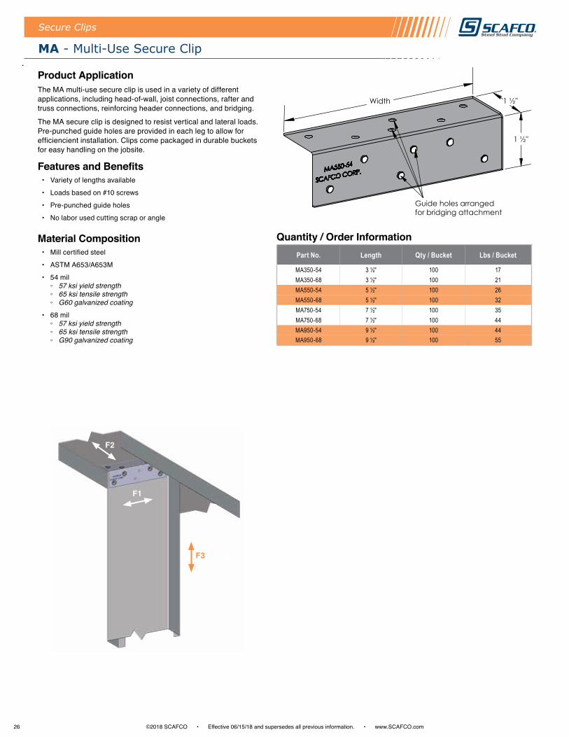
MA - Multi-Use Secure Clip
Product ApplicationThe MA multi-use secure clip is used in a variety of different applications, including head-of-wall, joist connections, rafter and truss connections, reinforcing header connections, and bridging .
The MA secure clip is designed to resist vertical and lateral loads . Pre-punched guide holes are provided in each leg to allow for efficiencient installation . Clips come packaged in durable buckets for easy handling on the jobsite .
Features and Benefits • Variety of lengths available
• Loads based on #10 screws
• Pre-punched guide holes
• No labor used cutting scrap or angle
Material Composition• Mill certified steel
• ASTM A653/A653M
• 54 mil ◦ 57 ksi yield strength ◦ 65 ksi tensile strength ◦ G60 galvanized coating
• 68 mil ◦ 57 ksi yield strength ◦ 65 ksi tensile strength ◦ G90 galvanized coating
Part No. Length Qty / Bucket Lbs / Bucket
MA350-54 3 ½" 100 17MA350-68 3 ½" 100 21MA550-54 5 ½" 100 26MA550-68 5 ½" 100 32MA750-54 7 ½" 100 35MA750-68 7 ½" 100 44MA950-54 9 ½" 100 44MA950-68 9 ½" 100 55
Quantity / Order Information
F1
F3
F2
1 ½"
Width 1 ½"
Guide holes arranged for bridging attachment

27©2018 SCAFCO • Effective 06/15/18 and supersedes all previous information . • www .SCAFCO .com
MA - Multi-Use Secure Clip Allowable Loads
Secure Clips
1 . Allowable loads have not been increased for wind, seismic activity, or other factors . 2 . The allowable loads are based on the steel properties of the members being
connected, per AISI S100 .3 . The nominal strength of the screw must be at least 3 .75 times the allowable load .4 . Screw shear capacities are based on allowable strength design (ASD) and include a
safety factor of 3 .0 .
5 . Penetration of screws through joined materials should not be less than three exposed threads . Install and tighten screws in accordance with the screw manufacturer's recommendations .
6 . Allowable loads indicated on the table(s) are for force in single direction only . The designer shall use the combined forces check as required by AISI S100 if more than one force is applied to the connection .
Part No. Stud Properties F1 Allowable Loads (lbs) F2 Allowable Loads (lbs) F3 Allowable Loads (lbs)Mil Gauge Fy (ksi) 2 #10 Screws 5 #10 Screws 9 #10 Screws 2 #10 Screws 5#10 Screws 9 #10 Screws 2 #10 Screws 5 #10 Screws 9 #10 Screws
MA950
33EQS 20 57 402 1005 1809 206 516 929 206 516 92933 20 33 353 884 1590 168 419 754 168 419 754
43EQS 18 57 635 1587 2856 280 700 1260 280 700 126043 18 33 526 1315 2367 219 547 984 219 547 98454 16 50 1068 2671 4807 396 991 1740 396 991 174068 14 50 1510 3776 6100 499 1248 1740 499 1248 174097 12 50 2261 5652 6100 712 1740 1740 712 1740 1740
Maximum Allowable Clip Capacity Max F1 = 6100 lbs Max F2 = 1740 lbs Max F3 = 1740 lbs
Part No. Stud Properties F1 Allowable Loads (lbs) F2 Allowable Loads (lbs) F3 Allowable Loads (lbs)Mil Gauge Fy (ksi) 2 #10 Screws 4 #10 Screws 7 #10 Screws 2 #10 Screws 4 #10 Screws 7 #10 Screws 2 #10 Screws 4 #10 Screws 7 #10 Screws
MA750
33EQS 20 57 402 804 1407 206 413 722 206 413 72233 20 33 353 707 1237 168 335 597 168 335 597
43EQS 18 57 635 1269 2221 280 560 980 280 560 98043 18 33 526 1052 1841 219 437 765 219 437 76554 16 50 1068 2136 3739 396 792 1387 396 792 138768 14 50 1510 3021 5286 499 998 1740 499 998 174097 12 50 2261 4521 6100 712 1424 1740 712 1424 1740
Maximum Allowable Clip Capacity Max F1 = 6100 lbs Max F2 = 1740 lbs Max F3 = 1740 lbs
Part No. Stud Properties F1 Allowable Loads (lbs) F2 Allowable Loads (lbs) F3 Allowable Loads (lbs)Mil Gauge Fy (ksi) 2 #10 Screws 4 #10 Screws 5 #10 Screws 2 #10 Screws 4 #10 Screws 5 #10 Screws 2 #10 Screws 4 #10 Screws 5 #10 Screws
MA550
33EQS 20 57 402 804 1005 206 413 516 206 413 51633 20 33 353 707 884 168 335 419 168 335 419
43EQS 18 57 635 1269 1587 280 560 700 280 560 70043 18 33 526 1052 1315 219 437 547 219 437 54754 16 50 1068 2136 2671 396 792 855 396 792 85568 14 50 1510 2980 2980 499 855 855 499 855 85597 12 50 2261 2980 2980 712 855 855 712 855 855
Maximum Allowable Clip Capacity Max F1 = 2980 lbs Max F2 = 855 lbs Max F3 = 855 lbs
Part No. Stud Properties F1 Allowable Loads (lbs) F2 Allowable Loads (lbs) F3 Allowable Loads (lbs)Mil Gauge Fy (ksi) 2 #10 Screws 3 #10 Screws 2 #10 Screws 3 #10 Screws 2 #10 Screws 3 #10 Screws
MA350
33EQS 20 57 402 603 206 310 206 31033 20 33 353 530 168 251 168 251
43EQS 18 57 635 952 280 420 280 42043 18 33 526 789 219 328 219 32854 16 50 1068 1602 396 594 396 59468 14 50 1510 2266 499 749 499 74997 12 50 2261 2420 712 965 712 965
Maximum Allowable Clip Capacity Max F1 = 2420 lbs Max F2 = 965 lbs Max F3 = 965 lbs
Table Notes
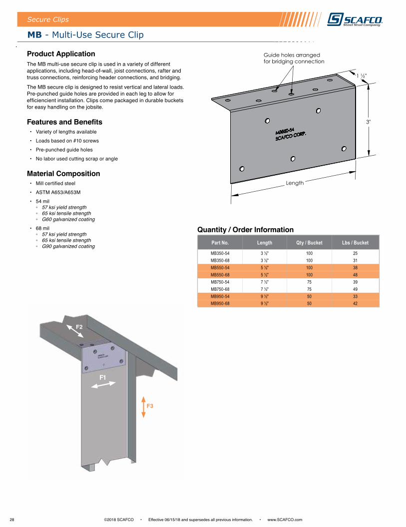
28 ©2018 SCAFCO • Effective 06/15/18 and supersedes all previous information . • www .SCAFCO .com
Secure Clips
MB - Multi-Use Secure Clip
Product ApplicationThe MB multi-use secure clip is used in a variety of different applications, including head-of-wall, joist connections, rafter and truss connections, reinforcing header connections, and bridging .
The MB secure clip is designed to resist vertical and lateral loads . Pre-punched guide holes are provided in each leg to allow for efficiencient installation . Clips come packaged in durable buckets for easy handling on the jobsite .
Features and Benefits • Variety of lengths available
• Loads based on #10 screws
• Pre-punched guide holes
• No labor used cutting scrap or angle
Material Composition• Mill certified steel
• ASTM A653/A653M
• 54 mil ◦ 57 ksi yield strength ◦ 65 ksi tensile strength ◦ G60 galvanized coating
• 68 mil ◦ 57 ksi yield strength ◦ 65 ksi tensile strength ◦ G90 galvanized coating
Quantity / Order InformationPart No. Length Qty / Bucket Lbs / Bucket
MB350-54 3 ½" 100 25MB350-68 3 ½" 100 31MB550-54 5 ½" 100 38MB550-68 5 ½" 100 48MB750-54 7 ½" 75 39MB750-68 7 ½" 75 49MB950-54 9 ½" 50 33MB950-68 9 ½" 50 42
F1
F3
F2
3"
Length
1 ½"
Guide holes arranged for bridging connection
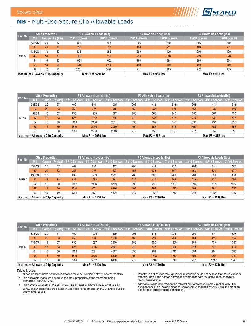
29©2018 SCAFCO • Effective 06/15/18 and supersedes all previous information . • www .SCAFCO .com
MB - Multi-Use Secure Clip Allowable Loads
Secure Clips
1 . Allowable loads have not been increased for wind, seismic activity, or other factors . 2 . The allowable loads are based on the steel properties of the members being
connected, per AISI S100 .3 . The nominal strength of the screw must be at least 3 .75 times the allowable load .4 . Screw shear capacities are based on allowable strength design (ASD) and include a
safety factor of 3 .0 .
5 . Penetration of screws through joined materials should not be less than three exposed threads . Install and tighten screws in accordance with the screw manufacturer's recommendations .
6 . Allowable loads indicated on the table(s) are for force in single direction only . The designer shall use the combined forces check as required by AISI S100 if more than one force is applied to the connection .
Part No. Stud Properties F1 Allowable Loads (lbs) F2 Allowable Loads (lbs) F3 Allowable Loads (lbs)Mil Gauge Fy (ksi) 2 #10 Screws 5 #10 Screws 9 #10 Screws 2 #10 Screws 5#10 Screws 9 #10 Screws 2 #10 Screws 5 #10 Screws 9 #10 Screws
MB950
33EQS 20 57 402 1005 1809 206 516 929 206 516 92933 20 33 353 884 1590 168 419 754 168 419 754
43EQS 18 57 635 1587 2856 280 700 1260 280 700 126043 18 33 526 1315 2367 219 547 984 219 547 98454 16 50 1068 2671 4807 396 991 1740 396 991 174068 14 50 1510 3776 6100 499 1248 1740 499 1248 174097 12 50 2261 5652 6100 712 1740 1740 712 1740 1740
Maximum Allowable Clip Capacity Max F1 = 6100 lbs Max F2 = 1740 lbs Max F3 = 1740 lbs
Part No. Stud Properties F1 Allowable Loads (lbs) F2 Allowable Loads (lbs) F3 Allowable Loads (lbs)Mil Gauge Fy (ksi) 2 #10 Screws 4 #10 Screws 7 #10 Screws 2 #10 Screws 4 #10 Screws 7 #10 Screws 2 #10 Screws 4 #10 Screws 7 #10 Screws
MB750
33EQS 20 57 402 804 1407 206 413 722 206 413 72233 20 33 353 707 1237 168 335 597 168 335 597
43EQS 18 57 635 1269 2221 280 560 980 280 560 98043 18 33 526 1052 1841 219 437 765 219 437 76554 16 50 1068 2136 3739 396 792 1387 396 792 138768 14 50 1510 3021 5286 499 998 1740 499 998 174097 12 50 2261 4521 6100 712 1424 1740 712 1424 1740
Maximum Allowable Clip Capacity Max F1 = 6100 lbs Max F2 = 1740 lbs Max F3 = 1740 lbs
Part No. Stud Properties F1 Allowable Loads (lbs) F2 Allowable Loads (lbs) F3 Allowable Loads (lbs)Mil Gauge Fy (ksi) 2 #10 Screws 4 #10 Screws 5 #10 Screws 2 #10 Screws 4 #10 Screws 5 #10 Screws 2 #10 Screws 4 #10 Screws 5 #10 Screws
MB550
33EQS 20 57 402 804 1005 206 413 516 206 413 51633 20 33 353 707 884 168 335 419 168 335 419
43EQS 18 57 635 1269 1587 280 560 700 280 560 70043 18 33 526 1052 1315 219 437 547 219 437 54754 16 50 1068 2136 2671 396 792 855 396 792 85568 14 50 1510 2980 2980 499 855 855 499 855 85597 12 50 2261 2980 2980 712 855 855 712 855 855
Maximum Allowable Clip Capacity Max F1 = 2980 lbs Max F2 = 855 lbs Max F3 = 855 lbs
Part No. Stud Properties F1 Allowable Loads (lbs) F2 Allowable Loads (lbs) F3 Allowable Loads (lbs)Mil Gauge Fy (ksi) 2 #10 Screws 3 #10 Screws 2 #10 Screws 3 #10 Screws 2 #10 Screws 3 #10 Screws
MB350
33EQS 20 57 402 603 206 310 206 31033 20 33 353 530 168 251 168 251
43EQS 18 57 635 952 280 420 280 42043 18 33 526 789 219 328 219 32854 16 50 1068 1602 396 594 396 59468 14 50 1510 2266 499 749 499 74997 12 50 2261 2420 712 965 712 965
Maximum Allowable Clip Capacity Max F1 = 2420 lbs Max F2 = 965 lbs Max F3 = 965 lbs
Table Notes

30 ©2018 SCAFCO • Effective 06/15/18 and supersedes all previous information . • www .SCAFCO .com
Secure Clips
MC - Multi-Use Secure Clip
Product ApplicationThe MC multi-use secure clip is used in a variety of different applications, including head-of-wall, joist connections, rafter and truss connections, and reinforcing header connections .
MC secure clips are designed to resist vertical and lateral loads . There are pre-punched guide holes provided in each leg to allow for efficiencient installation . Clips come packaged in durable buckets for easy handling on the jobsite .
Features and Benefits • Variety of lengths available
• Loads based on #10 screws
• Pre-punched guide holes
• No labor used cutting scrap or angle
Material Composition• Mill certified steel
• ASTM A653/A653M
• 54 mil ◦ 57 ksi yield strength ◦ 65 ksi tensile strength ◦ G60 galvanized coating
• 68 mil ◦ 57 ksi yield strength ◦ 65 ksi tensile strength ◦ G90 galvanized coating
Quantity / Order InformationPart No. Length Qty / Bucket Lbs / Bucket
MC350-54 3 ½" 100 33MC350-68 3 ½" 100 41MC550-54 5 ½" 100 51MC550-68 5 ½" 75 48MC750-54 7 ½" 50 35MC750-68 7 ½" 50 44MC950-54 9 ½" 50 44MC950-68 9 ½" 50 55
Length
3" 3"

31©2018 SCAFCO • Effective 06/15/18 and supersedes all previous information . • www .SCAFCO .com
MC - Multi-Use Secure Clip Allowable Loads
Secure Clips
1 . Allowable loads have not been increased for wind, seismic activity, or other factors . 2 . The allowable loads are based on the steel properties of the members being
connected, per AISI S100 .3 . The nominal strength of the screw must be at least 3 .75 times the allowable load .4 . Screw shear capacities are based on allowable strength design (ASD) and include a
safety factor of 3 .0 .
5 . Penetration of screws through joined materials should not be less than three exposed threads . Install and tighten screws in accordance with the screw manufacturer's recommendations .
6 . Allowable loads indicated on the table(s) are for force in single direction only . The designer shall use the combined forces check as required by AISI S100 if more than one force is applied to the connection .
Part No. Stud Properties F1 Allowable Loads (lbs) F2 Allowable Loads (lbs) F3 Allowable Loads (lbs)Mil Gauge Fy (ksi) 2 #10 Screws 5 #10 Screws 9 #10 Screws 2 #10 Screws 5#10 Screws 9 #10 Screws 2 #10 Screws 5 #10 Screws 9 #10 Screws
MC950
33EQS 20 57 402 1005 1809 206 516 929 206 516 92933 20 33 353 884 1590 168 419 754 168 419 754
43EQS 18 57 635 1587 2856 280 700 1260 280 700 126043 18 33 526 1315 2367 219 547 984 219 547 98454 16 50 1068 2671 4807 396 991 1740 396 991 174068 14 50 1510 3776 6100 499 1248 1740 499 1248 174097 12 50 2261 5652 6100 712 1740 1740 712 1740 1740
Maximum Allowable Clip Capacity Max F1 = 6100 lbs Max F2 = 1740 lbs Max F3 = 1740 lbs
Part No. Stud Properties F1 Allowable Loads (lbs) F2 Allowable Loads (lbs) F3 Allowable Loads (lbs)Mil Gauge Fy (ksi) 2 #10 Screws 4 #10 Screws 7 #10 Screws 2 #10 Screws 4 #10 Screws 7 #10 Screws 2 #10 Screws 4 #10 Screws 7 #10 Screws
MC750
33EQS 20 57 402 804 1407 206 413 722 206 413 72233 20 33 353 707 1237 168 335 597 168 335 597
43EQS 18 57 635 1269 2221 280 560 980 280 560 98043 18 33 526 1052 1841 219 437 765 219 437 76554 16 50 1068 2136 3739 396 792 1387 396 792 138768 14 50 1510 3021 5286 499 998 1740 499 998 174097 12 50 2261 4521 6100 712 1424 1740 712 1424 1740
Maximum Allowable Clip Capacity Max F1 = 6100 lbs Max F2 = 1740 lbs Max F3 = 1740 lbs
Part No. Stud Properties F1 Allowable Loads (lbs) F2 Allowable Loads (lbs) F3 Allowable Loads (lbs)Mil Gauge Fy (ksi) 2 #10 Screws 4 #10 Screws 5 #10 Screws 2 #10 Screws 4 #10 Screws 5 #10 Screws 2 #10 Screws 4 #10 Screws 5 #10 Screws
MC550
33EQS 20 57 402 804 1005 206 413 516 206 413 51633 20 33 353 707 884 168 335 419 168 335 419
43EQS 18 57 635 1269 1587 280 560 700 280 560 70043 18 33 526 1052 1315 219 437 547 219 437 54754 16 50 1068 2136 2671 396 792 855 396 792 85568 14 50 1510 2980 2980 499 855 855 499 855 85597 12 50 2261 2980 2980 712 855 855 712 855 855
Maximum Allowable Clip Capacity Max F1 = 2980 lbs Max F2 = 855 lbs Max F3 = 855 lbs
Part No. Stud Properties F1 Allowable Loads (lbs) F2 Allowable Loads (lbs) F3 Allowable Loads (lbs)Mil Gauge Fy (ksi) 2 #10 Screws 3 #10 Screws 2 #10 Screws 3 #10 Screws 2 #10 Screws 3 #10 Screws
MC350
33EQS 20 57 402 603 206 310 206 31033 20 33 353 530 168 251 168 251
43EQS 18 57 635 952 280 420 280 42043 18 33 526 789 219 328 219 32854 16 50 1068 1602 396 594 396 59468 14 50 1510 2266 499 749 499 74997 12 50 2261 2420 712 965 712 965
Maximum Allowable Clip Capacity Max F1 = 2420 lbs Max F2 = 965 lbs Max F3 = 965 lbs
Table Notes
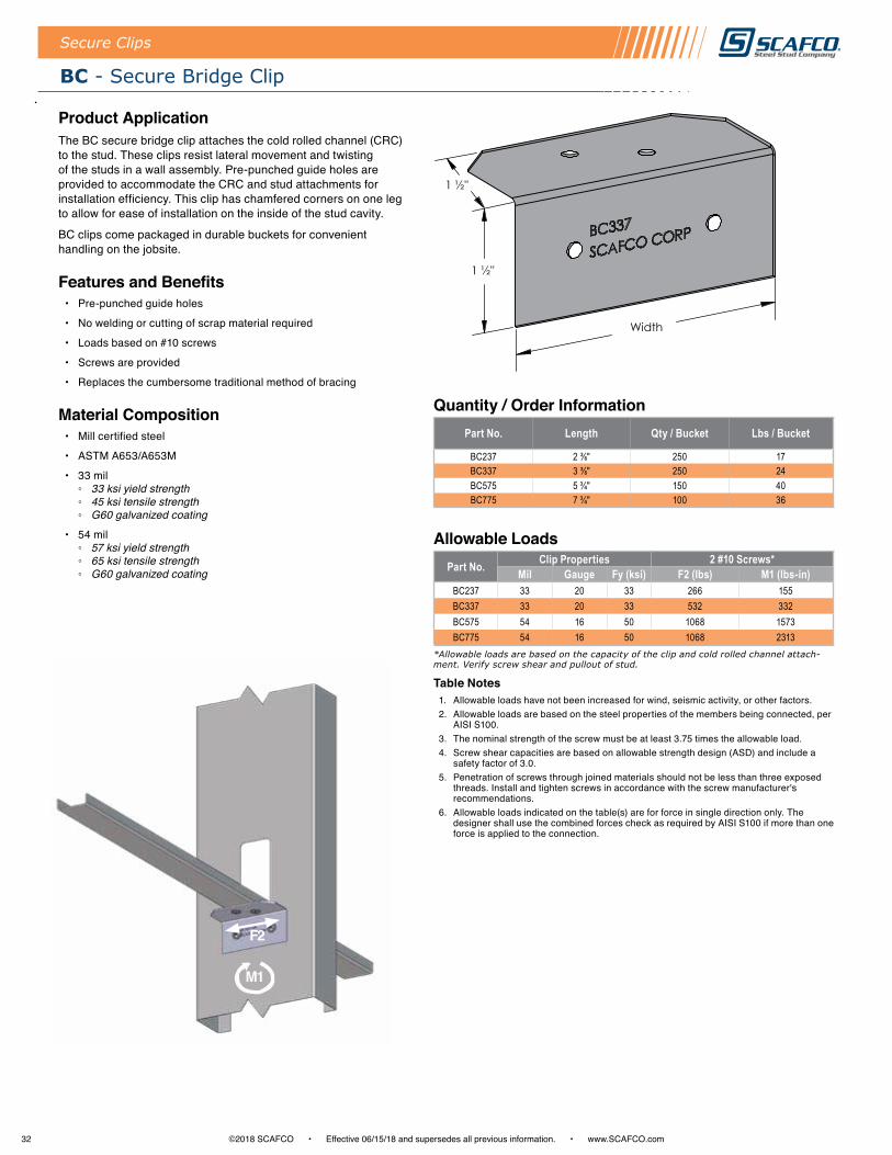
32 ©2018 SCAFCO • Effective 06/15/18 and supersedes all previous information . • www .SCAFCO .com
Allowable Loads
Part No. Length Qty / Bucket Lbs / Bucket
BC237 2 ⅜" 250 17BC337 3 ⅜" 250 24BC575 5 ¾" 150 40BC775 7 ¾" 100 36
Quantity / Order Information
Secure Clips
BC - Secure Bridge Clip
Product ApplicationThe BC secure bridge clip attaches the cold rolled channel (CRC) to the stud . These clips resist lateral movement and twisting of the studs in a wall assembly . Pre-punched guide holes are provided to accommodate the CRC and stud attachments for installation efficiency . This clip has chamfered corners on one leg to allow for ease of installation on the inside of the stud cavity .
BC clips come packaged in durable buckets for convenient handling on the jobsite .
Features and Benefits • Pre-punched guide holes
• No welding or cutting of scrap material required
• Loads based on #10 screws
• Screws are provided
• Replaces the cumbersome traditional method of bracing
Material Composition• Mill certified steel
• ASTM A653/A653M
• 33 mil ◦ 33 ksi yield strength ◦ 45 ksi tensile strength ◦ G60 galvanized coating
• 54 mil ◦ 57 ksi yield strength ◦ 65 ksi tensile strength ◦ G60 galvanized coating Part No. Clip Properties 2 #10 Screws*
Mil Gauge Fy (ksi) F2 (lbs) M1 (lbs-in)BC237 33 20 33 266 155BC337 33 20 33 532 332BC575 54 16 50 1068 1573BC775 54 16 50 1068 2313
*Allowable loads are based on the capacity of the clip and cold rolled channel attach-ment. Verify screw shear and pullout of stud.
Table Notes1 . Allowable loads have not been increased for wind, seismic activity, or other factors . 2 . Allowable loads are based on the steel properties of the members being connected, per
AISI S100 .3 . The nominal strength of the screw must be at least 3 .75 times the allowable load .4 . Screw shear capacities are based on allowable strength design (ASD) and include a
safety factor of 3 .0 .5 . Penetration of screws through joined materials should not be less than three exposed
threads . Install and tighten screws in accordance with the screw manufacturer's recommendations .
6 . Allowable loads indicated on the table(s) are for force in single direction only . The designer shall use the combined forces check as required by AISI S100 if more than one force is applied to the connection .
F2
M1
1 ½"
1 ½"
Width
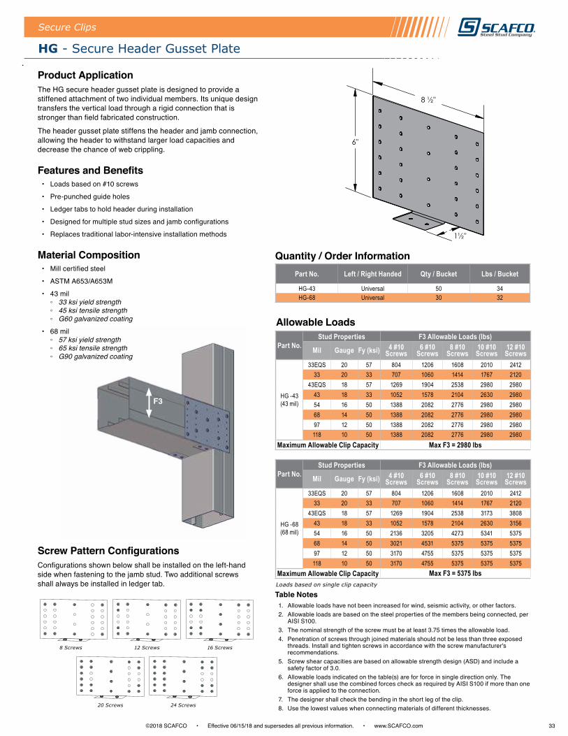
33©2018 SCAFCO • Effective 06/15/18 and supersedes all previous information . • www .SCAFCO .com
Allowable Loads
Part No. Left / Right Handed Qty / Bucket Lbs / Bucket
HG-43 Universal 50 34HG-68 Universal 30 32
Quantity / Order Information
Secure Clips
HG - Secure Header Gusset Plate
Product ApplicationThe HG secure header gusset plate is designed to provide a stiffened attachment of two individual members . Its unique design transfers the vertical load through a rigid connection that is stronger than field fabricated construction .
The header gusset plate stiffens the header and jamb connection, allowing the header to withstand larger load capacities and decrease the chance of web crippling .
Features and Benefits • Loads based on #10 screws
• Pre-punched guide holes
• Ledger tabs to hold header during installation
• Designed for multiple stud sizes and jamb configurations
• Replaces traditional labor-intensive installation methods
Material Composition• Mill certified steel
• ASTM A653/A653M
• 43 mil ◦ 33 ksi yield strength ◦ 45 ksi tensile strength ◦ G60 galvanized coating
• 68 mil ◦ 57 ksi yield strength ◦ 65 ksi tensile strength ◦ G90 galvanized coating
Part No.Stud Properties F3 Allowable Loads (lbs)
Mil Gauge Fy (ksi) 4 #10 Screws
6 #10 Screws
8 #10 Screws
10 #10 Screws
12 #10 Screws
HG -43 (43 mil)
33EQS 20 57 804 1206 1608 2010 241233 20 33 707 1060 1414 1767 2120
43EQS 18 57 1269 1904 2538 2980 298043 18 33 1052 1578 2104 2630 298054 16 50 1388 2082 2776 2980 298068 14 50 1388 2082 2776 2980 298097 12 50 1388 2082 2776 2980 2980118 10 50 1388 2082 2776 2980 2980
Maximum Allowable Clip Capacity Max F3 = 2980 lbs
Part No.Stud Properties F3 Allowable Loads (lbs)
Mil Gauge Fy (ksi) 4 #10 Screws
6 #10 Screws
8 #10 Screws
10 #10 Screws
12 #10 Screws
HG -68 (68 mil)
33EQS 20 57 804 1206 1608 2010 241233 20 33 707 1060 1414 1767 2120
43EQS 18 57 1269 1904 2538 3173 380843 18 33 1052 1578 2104 2630 315654 16 50 2136 3205 4273 5341 537568 14 50 3021 4531 5375 5375 537597 12 50 3170 4755 5375 5375 5375118 10 50 3170 4755 5375 5375 5375
Maximum Allowable Clip Capacity Max F3 = 5375 lbsLoads based on single clip capacity
Screw Pattern ConfigurationsConfigurations shown below shall be installed on the left-hand side when fastening to the jamb stud . Two additional screws shall always be installed in ledger tab .
8 Screws 12 Screws 16 Screws
24 Screws20 Screws
F3
Table Notes1 . Allowable loads have not been increased for wind, seismic activity, or other factors . 2 . Allowable loads are based on the steel properties of the members being connected, per
AISI S100 .3 . The nominal strength of the screw must be at least 3 .75 times the allowable load .4 . Penetration of screws through joined materials should not be less than three exposed
threads . Install and tighten screws in accordance with the screw manufacturer's recommendations .
5 . Screw shear capacities are based on allowable strength design (ASD) and include a safety factor of 3 .0 .
6 . Allowable loads indicated on the table(s) are for force in single direction only . The designer shall use the combined forces check as required by AISI S100 if more than one force is applied to the connection .
7 . The designer shall check the bending in the short leg of the clip .8 . Use the lowest values when connecting materials of different thicknesses .
6"
8 ½"
1½"
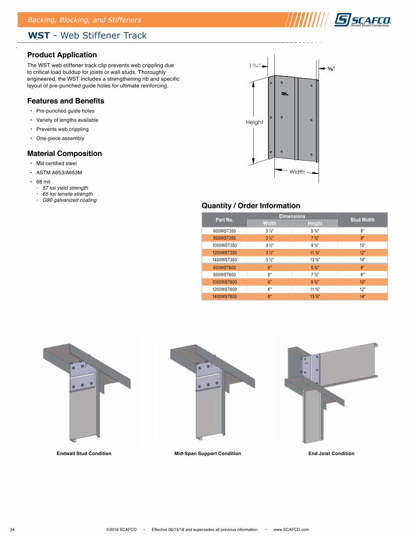
34 ©2018 SCAFCO • Effective 06/15/18 and supersedes all previous information . • www .SCAFCO .com
Quantity / Order Information
Backing, Blocking, and Stiffeners
WST - Web Stiffener Track
Product ApplicationThe WST web stiffener track clip prevents web crippling due to critical load buildup for joists or wall studs . Thoroughly engineered, the WST includes a strengthening rib and specific layout of pre-punched guide holes for ultimate reinforcing .
Features and Benefits • Pre-punched guide holes
• Variety of lengths available
• Prevents web crippling
• One-piece assembly
Material Composition• Mill certified steel
• ASTM A653/A653M
• 68 mil ◦ 57 ksi yield strength ◦ 65 ksi tensile strength ◦ G90 galvanized coating
End Joist ConditionEndwall Stud Condition Mid-Span Support Condition
Part No. Dimensions Stud WidthWidth Height600WST350 3 ½" 5 ⅝" 6"800WST350 3 ½" 7 ⅝" 8"1000WST350 3 ½" 9 ⅝" 10"1200WST350 3 ½" 11 ⅝" 12"1400WST350 3 ½" 13 ⅝" 14"600WST600 6" 5 ⅝" 6"800WST600 6" 7 ⅝" 8"1000WST600 6" 9 ⅝" 10"1200WST600 6" 11 ⅝" 12"1400WST600 6" 13 ⅝" 14"
Backing, Blocking, and Stiffeners
Height
Width
1 " ⅝"

35©2018 SCAFCO • Effective 06/15/18 and supersedes all previous information . • www .SCAFCO .com
Product ApplicationThe Kwik-Bridge Punch System is a unique patented design that incorporates a tab into the punchout of the stud, resulting in a clean connection and reduced labor . The Kwik-Bridge Punch System eliminates extra components required in traditional bridging installation and can be used with regular cold roll channel (CRC) .
The CRC is installed through the stud punchouts perpendicular to the framing and at a pre-determined spacing along the height of the wall . Once the channel is positioned horizontally within the wall cavity, a method of securing the channel to each individual stud will be selected according to the design criteria for the assembly .
Typically, positive attachment is achieved through welding or by using angle clips and screws . The Kwik-Bridge Punch System serves as an alternative method of achieving positive attachment of the cold rolled channel to the steel stud . Patent No . 5943838 .
Features and Benefits • Eliminates use of clip angles, bridging clips, and welding
• No pre-determined stud layout required
• Faster installation, saving up to 40% in combined labor and material costs
• Bend tabs to 90° and attach cold roll channel with only 2 screws
• Contact Technical@SCAFCO .com for allowable loads
Material Composition• Mill certified steel
• ASTM A653/A653M
• Available mil thicknesses ◦ 18, D20, 30EQD, 33EQD, 33EQS, 43EQS, 30, 33, 43, and 54
(not available in D25, 68, 97, or 118)
• Available web widths ◦ 3 ½", 3 ⅝", 4", 5 ½", and 6"
(not available in 1 ⅝", 2 ½", or 8" and over)
Nomenclature ExampleThe Kwik-Bridge Punch System uses the standard SSMA/SSFSA nomenclature, but adds a letter "K" at the end of the product identification . Use the following example when ordering studs with the Kwik-Bridge Punch System .
K - Kwik-Bridge Punch System
Backing, Blocking, and Stiffeners
600 162 43 KS 10
6" Web Width1 ⅝"
Leg Width Length in ft
43 mil Kwik-BridgePunch System
Stud
- -

36 ©2018 SCAFCO • Effective 06/15/18 and supersedes all previous information . • www .SCAFCO .com
Backing, Blocking, and Stiffeners
ELEV - Elevator Stud Clip
Product ApplicationThe ELEV elevator stud clip is used to join two shorter stud members into one long member for jobsites where elevator transportation limits the allowable stud length .
Features and Benefits • Available in widths of 3 .5" to 6"
◦ Other widths available upon request
• Available in standard 24" lengths
• Pre-punched guide holes
• Customizes lengths without additional cutting
• Splice design calculations available, contact Technical@SCAFCO .com
Material Composition• Mill certified steel
• ASTM: A653/A653M
• 33 mil ◦ 33 ksi yield strength ◦ 45 ksi tensile strength ◦ G60 galvanized coating
Nomenclature Example
Table Notes 1 . ELEV Clips come in 24" standard length . Custom length available upon request .2 . ELEV Clips come with standard 1½" legs . Longer legs available upon request .
150ELEV600 33
Part Designation Thickness
Flange Width
Web Width
-Part No. Stud Dimensions
Width * Flange350ELEV150-33 3 ½" 150362ELEV150-33 3 ⅝" 150400ELEV150-33 4" 150550ELEV150-33 5 ½" 150600ELEV150-33 6" 150
Quantity / Order Information
Elevator Stud Splice Track Clip Near Head of Wall
Elevator Stud Splice Track Clip at Midpoint
24"
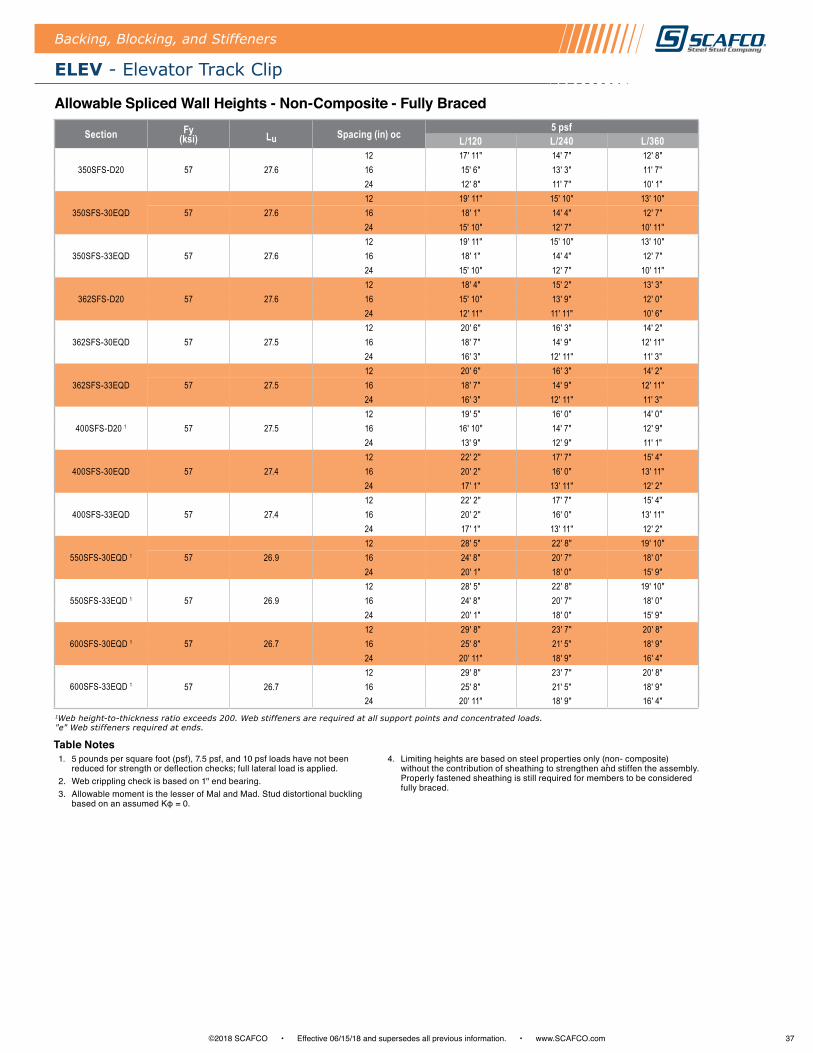
37©2018 SCAFCO • Effective 06/15/18 and supersedes all previous information . • www .SCAFCO .com
ELEV - Elevator Track Clip
Backing, Blocking, and Stiffeners
Section Fy (ksi) Lu Spacing (in) oc 5 psf
L/120 L/240 L/360
350SFS-D2012 17' 11" 14' 7" 12' 8"
57 27.6 16 15' 6" 13' 3" 11' 7"24 12' 8" 11' 7" 10' 1"
350SFS-30EQD12 19' 11" 15' 10" 13' 10"
57 27.6 16 18' 1" 14' 4" 12' 7"24 15' 10" 12' 7" 10' 11"
350SFS-33EQD12 19' 11" 15' 10" 13' 10"
57 27.6 16 18' 1" 14' 4" 12' 7"24 15' 10" 12' 7" 10' 11"
362SFS-D2012 18' 4" 15' 2" 13' 3"
57 27.6 16 15' 10" 13' 9" 12' 0"24 12' 11" 11' 11" 10' 6"
362SFS-30EQD12 20' 6" 16' 3" 14' 2"
57 27.5 16 18' 7" 14' 9" 12' 11"24 16' 3" 12' 11" 11' 3"
362SFS-33EQD12 20' 6" 16' 3" 14' 2"
57 27.5 16 18' 7" 14' 9" 12' 11"24 16' 3" 12' 11" 11' 3"
400SFS-D20 1
12 19' 5" 16' 0" 14' 0"57 27.5 16 16' 10" 14' 7" 12' 9"
24 13' 9" 12' 9" 11' 1"
400SFS-30EQD12 22' 2" 17' 7" 15' 4"
57 27.4 16 20' 2" 16' 0" 13' 11"24 17' 1" 13' 11" 12' 2"
400SFS-33EQD12 22' 2" 17' 7" 15' 4"
57 27.4 16 20' 2" 16' 0" 13' 11"24 17' 1" 13' 11" 12' 2"
550SFS-30EQD 1
12 28' 5" 22' 8" 19' 10"57 26.9 16 24' 8" 20' 7" 18' 0"
24 20' 1" 18' 0" 15' 9"
550SFS-33EQD 1
12 28' 5" 22' 8" 19' 10"57 26.9 16 24' 8" 20' 7" 18' 0"
24 20' 1" 18' 0" 15' 9"
600SFS-30EQD 1
12 29' 8" 23' 7" 20' 8"57 26.7 16 25' 8" 21' 5" 18' 9"
24 20' 11" 18' 9" 16' 4"
600SFS-33EQD 1
12 29' 8" 23' 7" 20' 8"57 26.7 16 25' 8" 21' 5" 18' 9"
24 20' 11" 18' 9" 16' 4"
Table Notes 1 . 5 pounds per square foot (psf), 7 .5 psf, and 10 psf loads have not been
reduced for strength or deflection checks; full lateral load is applied .2 . Web crippling check is based on 1" end bearing .3 . Allowable moment is the lesser of Mal and Mad . Stud distortional buckling
based on an assumed Kφ = 0.
4 . Limiting heights are based on steel properties only (non- composite) without the contribution of sheathing to strengthen and stiffen the assembly . Properly fastened sheathing is still required for members to be considered fully braced .
1Web height-to-thickness ratio exceeds 200. Web stiffeners are required at all support points and concentrated loads. "e" Web stiffeners required at ends.
Allowable Spliced Wall Heights - Non-Composite - Fully Braced

38 ©2018 SCAFCO • Effective 06/15/18 and supersedes all previous information . • www .SCAFCO .com
Backing, Blocking, and Stiffeners
TB - Track Backing
Product ApplicationTB solid track blocking provides horizontal bracing for studs and joists . Solid track blocking is thoroughly engineered for 12", 16", and 24" stud layouts .
Features and Benefits • Available in 12", 16", and 24" stud spacing
• Custom lengths available upon request
• Pre-punched guide holes
• One-piece assembly
Material Composition• Mill certified steel
• ASTM A653/A653M
• 54 mil ◦ 57 ksi yield strength ◦ 65 ksi tensile strength ◦ G60 galvanized coating
Nomenclature Example
162362TB S24 54
Stud Web Width Spacing 24" oc
*Stud Flange Length
Track Blocking
54 mil
-- -
Quantity / Order Information
Part No. Stud DimensionsWidth * Flange Spacing
TB250-*-S12-54 2 ½" 125/162/200 12" TB250-*-S16-54 2 ½" 125/162/200 16"TB250-*-S24-54 2 ½" 125/162/200 24"TB350-*-S12-54 3 ½" 125/162/200 12" TB350-*-S16-54 3 ½" 125/162/200 16"TB350-*-S24-54 3 ½" 125/162/200 24"TB362-*-S12-54 3 ⅝" 125/162/200 12" TB362-*-S16-54 3 ⅝" 125/162/200 16"TB362-*-S24-54 3 ⅝" 125/162/200 24"TB400-*-S12-54 4" 125/162/200 12" TB400-*-S16-54 4" 125/162/200 16"TB400-*-S24-54 4" 125/162/200 24"
Part No. Stud DimensionsWidth * Flange Spacing
TB600-*-S12-54 6" 125/162/200 12" TB600-*-S16-54 6" 125/162/200 16"TB600-*-S24-54 6" 125/162/200 24"TB800-*-S12-54 8" 125/162/200 12" TB800-*-S16-54 8" 125/162/200 16"TB800-*-S24-54 8" 125/162/200 24"TB1000-*-S12-54 10" 125/162/200 12" TB1000-*-S16-54 10" 125/162/200 16"TB1000-*-S24-54 10" 125/162/200 24"TB1200-*-S12-54 12" 125/162/200 12" TB1200-*-S16-54 12" 125/162/200 16"TB1200-*-S24-54 12" 125/162/200 24"
Stud Spacing
Pre-Punched Guide Holes
Width

39©2018 SCAFCO • Effective 06/15/18 and supersedes all previous information . • www .SCAFCO .com
FTB - Fire Track Blocking (Shear Blocking)
Backing, Blocking, and Stiffeners
Product ApplicationFTB fire track blocking provides horizontal bracing for studs and joists . Fire track blocking is thoroughly engineered for 12", 16", and 24" stud layouts with a precut flange to fit inside the stud cavity for quick installation .
FTB is also a great option for shear wall blocking and prevention of issues with in-plane load transfer . FTB provides full bearing between the wall stud webs along the shear wall .
Features and Benefits • Available in 12", 16", and 24" stud spacing
• Custom lengths available upon request
• Pre-punched guide holes
• One-piece assembly
• Fills the whole stud cavity
Material Composition• Mill certified steel
• ASTM A653/A653M
• 54 mil ◦ 57 ksi yield strength ◦ 65 ksi tensile strength ◦ G60 galvanized coating
Nomenclature Example
162362FTB S24 54
Stud Web Width Spacing 24" oc
*Stud Flange Length
Fire Track Blocking
54 mil
-- -
Quantity / Order Information
Part No. Stud DimensionsWidth * Flange Spacing
FTB250-*-S12-54 2 ½" 125/162/200 12" FTB250-*-S16-54 2 ½" 125/162/200 16"FTB250-*-S24-54 2 ½" 125/162/200 24"FTB350-*-S12-54 3 ½" 125/162/200 12" FTB350-*-S16-54 3 ½" 125/162/200 16"FTB350-*-S24-54 3 ½" 125/162/200 24"FTB362-*-S12-54 3 ⅝" 125/162/200 12" FTB362-*-S16-54 3 ⅝" 125/162/200 16"FTB362-*-S24-54 3 ⅝" 125/162/200 24"FTB400-*-S12-54 4" 125/162/200 12" FTB400-*-S16-54 4" 125/162/200 16"FTB400-*-S24-54 4" 125/162/200 24"FTB600-*-S12-54 6" 125/162/200 12" FTB600-*-S16-54 6" 125/162/200 16"FTB600-*-S24-54 6" 125/162/200 24"FTB800-*-S12-54 8" 125/162/200 12" FTB800-*-S16-54 8" 125/162/200 16"FTB800-*-S24-54 8" 125/162/200 24"FTB1000-*-S12-54 10" 125/162/200 12" FTB1000-*-S16-54 10" 125/162/200 16"FTB1000-*-S24-54 10" 125/162/200 24"FTB1200-*-S12-54 12" 125/162/200 12" FTB1200-*-S16-54 12" 125/162/200 16"FTB1200-*-S24-54 12" 125/162/200 24"
Stud Spacing
Pre-Punched Guide Holes
Width
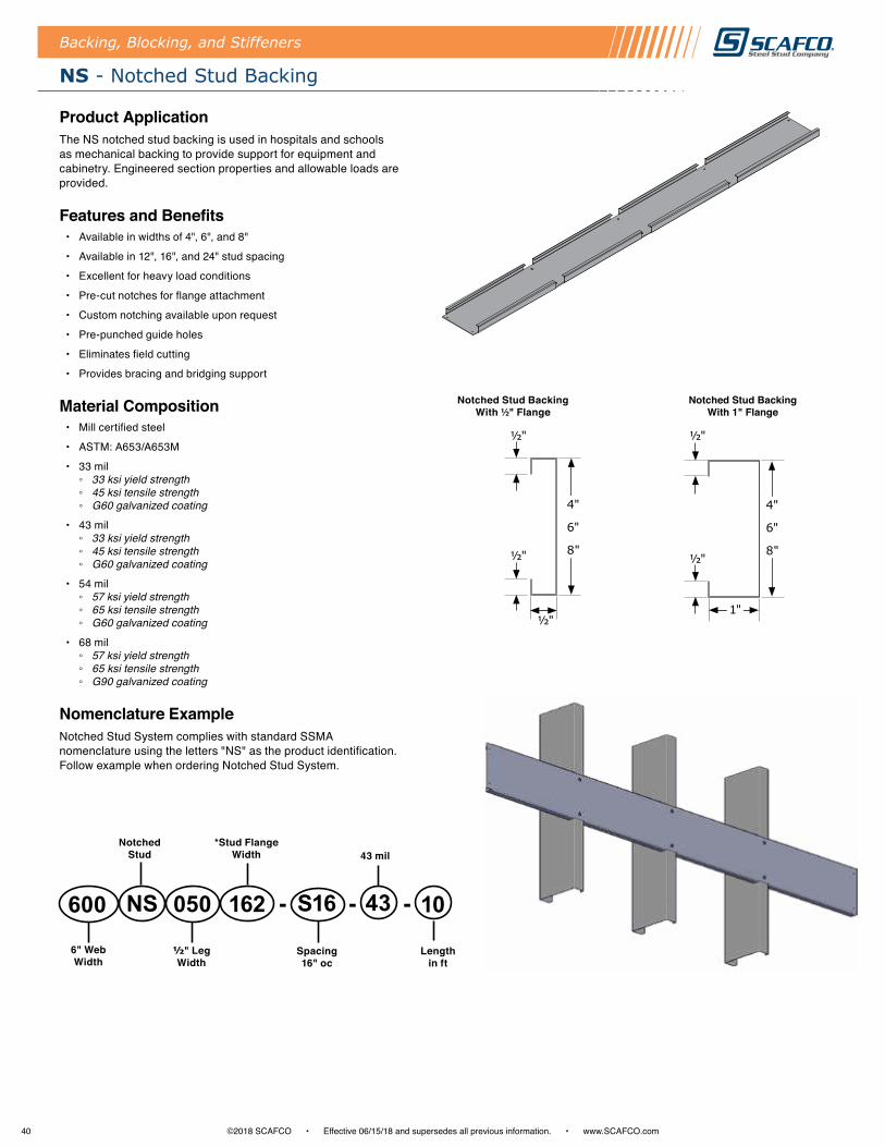
40 ©2018 SCAFCO • Effective 06/15/18 and supersedes all previous information . • www .SCAFCO .com
Backing, Blocking, and Stiffeners
NS - Notched Stud Backing
Product ApplicationThe NS notched stud backing is used in hospitals and schools as mechanical backing to provide support for equipment and cabinetry . Engineered section properties and allowable loads are provided .
Features and Benefits • Available in widths of 4", 6", and 8"
• Available in 12", 16", and 24" stud spacing
• Excellent for heavy load conditions
• Pre-cut notches for flange attachment
• Custom notching available upon request
• Pre-punched guide holes
• Eliminates field cutting
• Provides bracing and bridging support
Material Composition• Mill certified steel
• ASTM: A653/A653M
• 33 mil ◦ 33 ksi yield strength ◦ 45 ksi tensile strength ◦ G60 galvanized coating
• 43 mil ◦ 33 ksi yield strength ◦ 45 ksi tensile strength ◦ G60 galvanized coating
• 54 mil ◦ 57 ksi yield strength ◦ 65 ksi tensile strength ◦ G60 galvanized coating
• 68 mil ◦ 57 ksi yield strength ◦ 65 ksi tensile strength ◦ G90 galvanized coating
Nomenclature ExampleNotched Stud System complies with standard SSMA nomenclature using the letters "NS" as the product identification . Follow example when ordering Notched Stud System .
050600 NS S16162 43 10
Notched Stud
Spacing 16" oc
*Stud Flange Width
½" Leg Width
6" Web Width
43 mil
Length in ft
-- -
Notched Stud Backing With ½" Flange
½"
½"
½"
4"
6"
8"
Notched Stud Backing With 1" Flange
½"
½"
1"
4"
6"
8"

41©2018 SCAFCO • Effective 06/15/18 and supersedes all previous information . • www .SCAFCO .com
Backing, Blocking, and Stiffeners
NS - Notched Stud Backing
Part No. Depth (in)
Flange (in) * Vertical Stud Flange Properties
Ixe (min) (in4) Sxe (min) (in3) Iye (min) (in4) Sye (min) (in3)400NS050-*-S??-33 4 0.50 125/162/200 0.386 0.193 0.007 0.018400NS050-*-S??-43 4 0.50 125/162/200 0.495 0.248 0.008 0.022400NS050-*-S??-54 4 0.50 125/162/200 0.603 0.301 0.009 0.025400NS050-*-S??-68 4 0.50 125/162/200 0.728 0.364 0.011 0.029600NS050-*-S??-33 6 0.50 125/162/200 1.085 0.357 0.007 0.018600NS050-*-S??-43 6 0.50 125/162/200 1.416 0.472 0.009 0.022600NS050-*-S??-54 6 0.50 125/162/200 1.736 0.579 0.010 0.026600NS050-*-S??-68 6 0.50 125/162/200 2.116 0.705 0.012 0.030800NS050-*-S??-33 8 0.50 125/162/200 2.214 0.526 0.007 0.018800NS050-*-S??-43 8 0.50 125/162/200 2.989 0.738 0.009 0.022800NS050-*-S??-54 8 0.50 125/162/200 3.727 0.932 0.011 0.026800NS050-*-S??-68 8 0.50 125/162/200 4.569 1.142 0.012 0.030400NS100-*-S??-33 4 1.00 125/162/200 0.522 0.261 0.033 0.046400NS100-*-S??-43 4 1.00 125/162/200 0.672 0.336 0.041 0.058400NS100-*-S??-54 4 1.00 125/162/200 0.823 0.411 0.050 0.070400NS100-*-S??-68 4 1.00 125/162/200 1.003 0.501 0.059 0.082600NS100-*-S??-33 6 1.00 125/162/200 1.371 0.445 0.036 0.047600NS100-*-S??-43 6 1.00 125/162/200 1.816 0.605 0.046 0.060600NS100-*-S??-54 6 1.00 125/162/200 2.236 0.745 0.056 0.072600NS100-*-S??-68 6 1.00 125/162/200 2.742 0.914 0.066 0.085800NS100-*-S??-331 8 1.00 125/162/200 2.687 0.626 0.037 0.047800NS100-*-S??-43 8 1.00 125/162/200 3.610 0.872 0.048 0.060800NS100-*-S??-54 8 1.00 125/162/200 4.492 1.092 0.058 0.072800NS100-*-S??-68 8 1.00 125/162/200 5.690 1.423 0.070 0.086
Part No. Stud Properties Vertical Pmax (lb) Spacing # of Screws Required for Vertical Pmax Spacing Horizontal Pmax (lb) Spacing # of Screws Required for
Horizontal Pmax SpacingMil Gauge Fy (ksi) 12" 16" 24" 12" 16" 24" 12" 16" 24" 12" 16" 24"
400NS050-*-S??-33 33 20 33 976 933 622 6 6 4 112 84 56 2 2 2400NS050-*-S??-43 43 18 33 1740 1593 1062 7 7 5 144 108 72 2 2 2400NS050-*-S??-54 54 16 50 3372 2934 1956 7 6 4 248 186 124 2 2 2400NS050-*-S??-68 68 14 50 4716 3537 2358 10 8 5 284 213 142 2 2 2600NS050-*-S??-33 33 20 33 638 638 638 4 4 4 112 84 56 2 2 2600NS050-*-S??-43 43 18 33 1416 1416 1416 6 6 6 140 105 70 2 2 2600NS050-*-S??-54 54 16 50 2823 2823 2706 6 6 6 248 186 124 2 2 2600NS050-*-S??-68 68 14 50 5350 5268 3512 11 11 8 284 213 142 2 2 2800NS050-*-S??-33 33 20 33 474 474 474 3 3 3 112 84 56 2 2 2800NS050-*-S??-43 43 18 33 1051 1051 1051 3 4 4 144 108 72 2 2 2800NS050-*-S??-54 54 16 50 2091 2091 2091 5 5 5 252 189 126 2 2 2800NS050-*-S??-68 68 14 50 4221 4221 4221 9 9 9 288 216 144 2 2 2400NS100-*-S??-33 33 20 33 976 976 860 6 6 5 288 216 144 4 3 2400NS100-*-S??-43 43 18 33 1739 1739 1280 7 7 5 372 279 186 4 3 2400NS100-*-S??-54 54 16 50 3372 3372 2398 7 7 5 680 510 340 4 3 2400NS100-*-S??-68 54 16 50 4871 4533 3022 10 10 7 816 612 408 4 3 2600NS100-*-S??-33 33 20 33 638 638 638 4 4 4 288 216 144 4 3 2600NS100-*-S??-43 43 18 33 1416 1416 1416 6 6 6 376 282 188 4 3 2600NS100-*-S??-54 54 16 50 2823 2823 2823 6 6 6 688 516 344 4 3 2600NS100-*-S??-68 68 14 50 5350 5350 4554 11 11 10 828 621 414 4 3 2800NS100-*-S??-33 33 20 33 474 474 474 3 3 3 292 219 146 4 3 2800NS100-*-S??-43 43 18 33 1051 1051 1051 4 4 4 380 285 190 4 3 2800NS100-*-S??-54 54 16 50 2091 2091 2091 4 4 4 692 519 346 4 3 2800NS100-*-S??-68 54 16 50 4221 4221 4221 9 9 9 832 624 416 4 3 2
S?? Represents the vertical stud spacing. Allowable Section Properties - Per AISI Design Criteria
Table Notes 1 . Web height to thickness ratio exceeds 200 . Web stiffeners are required at all support
points and for concentrated loads .2 . Maximum point load, Pmax, is determined based on the minimum of the shear capacity
or the bending capacity of the blocking/Part No ., or the number of screws with proper edge distance/spacing that may be installed . Load assumed to act at mid-span through centroid of Part No ., based on a span of 24" . For stud spacing of 16" oc, above tables may be used conservatively .
3 . Number of screws determined by dividing Pmax by capacity of #10 screw and rounding up . Screw manufacturer shall confirm that their screws meet the code-allowable capacity indicated in the table .
4 . Screw capacity based on stud material with thickness and yield strength equal to the blocking/Part No . Minimum screw spacing and edge distance shall not be less than 3 times the nominal screw diameter (per SSMA) . For #10 screw, 3 x d = 3 x 0 .190" = 0 .57" .
5 . The properties indicated in the table have been calculated using CFS version 5 .0 .2 (RSG Software Inc .) .
6 . Tabulated values do not consider stud capacity . Studs designed by others .7 . All calculations based on 2012 AISI .
Allowable Loads

42 ©2018 SCAFCO • Effective 06/15/18 and supersedes all previous information . • www .SCAFCO .com
NT - Notched Track Backing
Backing, Blocking, and Stiffeners
Product ApplicationThe NT is used in hospitals, schools, and other projects as mechanical backing that provides superior support for equipment and cabinetry .
Features and Benefits • Available in widths of 4", 6", and 8"
• Available in 12", 16", and 24" stud spacing
• Pre-cut notches for flange attachment
• Eliminates field cutting
Material Composition• Mill certified steel
• ASTM: A653/A653M
• 33 mil ◦ 33 ksi yield strength ◦ 45 ksi tensile strength ◦ G60 galvanized coating
• 43 mil ◦ 33 ksi yield strength ◦ 45 ksi tensile strength ◦ G60 galvanized coating
• 54 mil ◦ 57 ksi yield strength ◦ 65 ksi tensile strength ◦ G60 galvanized coating
• 68 mil ◦ 57 ksi yield strength ◦ 65 ksi tensile strength ◦ G90 galvanized coating
Nomenclature ExampleNotched track system complies with standard SSMA nomenclature using the letters "NT" as the product identification . Use the following example when ordering notched track system .
600 162 S24 10NT 43
*Stud Flange Width 43mil
Length in ft
Notched Track
- -
6" Web Width
Spacing 24" oc
*Notch opening will be ⅛" larger than the stud flange width.
Width
12", 16", and 24"Stud Spacing

43©2018 SCAFCO • Effective 06/15/18 and supersedes all previous information . • www .SCAFCO .com
Part No. Width Qty / Bucket Lbs / Bucket
KB162 1 ¼" to 1 ⅝" 100 25KB200 2" 100 27
Quantity / Order Information
KB - Kwik-Back Wall Support
Backing, Blocking, and Stiffeners
Product ApplicationKwik-Back clips are the most cost effective, labor saving solution to create superior backing support for wall shelving, cabinetry, heavy wall hangings, and other equipment .
Installation is simplified by using 2 or 3 screws to attach the clip to the stud flange . No pre-determined stud layout is required and ledge tabs are added for easy alignment . Attach 2" x 6" structure grade lumber (#1 or better) as required by code or specification .
Features and Benefits • Loads based on #8 screws
• Screws are provided
• Pre-punched guide holes
• Folded tabs for consistent wood positioning
Material Composition• Mill certified steel
• ASTM A653/A653M
• 33 mil ◦ 33 ksi yield strength ◦ 45 ksi tensile strength ◦ G60 galvanized coating
Table Notes1 . Allowable loads have not been increased for wind, seismic activity, or other factors . 2 . The allowable loads are based on the steel properties of the members being connected,
per AISI S100 .3 . The nominal strength of the screw must be at least 3 .75 times the allowable loads .4 . Screw shear capacities are based on allowable strength design (ASD) and include a
safety factor of 3 .0 .5 . Penetration of screws through joined materials should not be less than three exposed
threads . Install and tighten screws in accordance with the screw manufacturer's recommendations .
6 . Allowable loads indicated on the table(s) are for force in single direction only . The designer shall use the combined forces check as required by AISI S100 if more than one force is applied to the connection .
7 . Designer shall check screw capacity to wood backing material .
Part No.Stud Properties F1 Allowable Loads (lbs) F3 Allowable Loads (lbs)
Mil Gauge Fy (ksi) 2 #8 Screws
3 #8 Screws
2 #8 Screws
3 #8 Screws
KB
18 25 33 79 118 132 197D20 20 57 114 170 190 285
30EQD 20 57 142 213 266 39830 20 33 130 196 281 422
33EQS 20 (S) 57 178 267 373 56033 20 (S) 33 145 217 328 493
43EQS 18 57 242 342 460 68943 18 33 189 283 460 68954 16 50 342 342 460 689
Allowable Loads
F3
F1
Stud flange size
5"
Folded tabs for wood support

44 ©2018 SCAFCO • Effective 06/15/18 and supersedes all previous information . • www .SCAFCO .com
SCAFCO Specialty Products
Product ApplicationSCAFCO's ponywall supports are manufactured from prime domestic steel and assembled with certified welds, providing superior strength and durability . Its unique rigid design and ease of installation makes it the preferred choice over conventional ponywall construction methods . Ponywall supports are stocked in 34", 48", and 60" heights but can be special ordered to meet required design specifications .
Features and Benefits • Pre-punched guide holes
• Standard heights are 34", 48", and 60"
• Custom heights available
• Welded construction
Material Composition• Mill certified steel
• ASTM A653/A653M
• Support stud ◦ 97 mil ◦ 57 ksi yield strength ◦ 65 ksi tensile strength ◦ G90 galvanized coating
• Base plate ◦ 168 mil ◦ 57 ksi yield strength ◦ 65 ksi tensile strength ◦ G115 galvanized coating ◦
• Contact technical@SCAFCO .com for allowable loads
Ponywall Support
The upright support stud is made from a 362S250-97 stud centered and welded to the base plate .
3 ⅜"⅝"
14"
SCAFCO Specialty Products
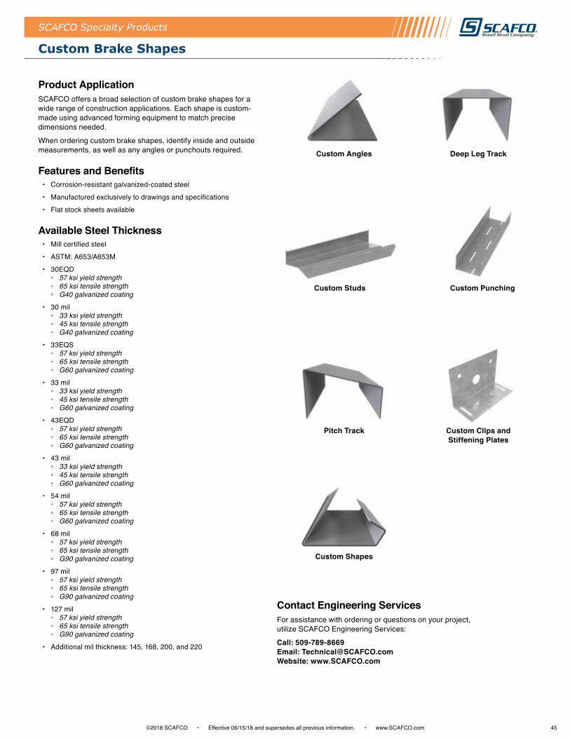
45©2018 SCAFCO • Effective 06/15/18 and supersedes all previous information . • www .SCAFCO .com
Custom Brake Shapes
SCAFCO Specialty Products
Custom Angles Deep Leg Track
Custom Shapes
Custom Clips and Stiffening Plates
Pitch Track
Custom PunchingCustom Studs
Product ApplicationSCAFCO offers a broad selection of custom brake shapes for a wide range of construction applications . Each shape is custom-made using advanced forming equipment to match precise dimensions needed .
When ordering custom brake shapes, identify inside and outside measurements, as well as any angles or punchouts required .
Features and Benefits • Corrosion-resistant galvanized-coated steel
• Manufactured exclusively to drawings and specifications
• Flat stock sheets available
Available Steel Thickness• Mill certified steel
• ASTM: A653/A653M
• 30EQD ◦ 57 ksi yield strength ◦ 65 ksi tensile strength ◦ G40 galvanized coating
• 30 mil ◦ 33 ksi yield strength ◦ 45 ksi tensile strength ◦ G40 galvanized coating
• 33EQS ◦ 57 ksi yield strength ◦ 65 ksi tensile strength ◦ G60 galvanized coating
• 33 mil ◦ 33 ksi yield strength ◦ 45 ksi tensile strength ◦ G60 galvanized coating
• 43EQD ◦ 57 ksi yield strength ◦ 65 ksi tensile strength ◦ G60 galvanized coating
• 43 mil ◦ 33 ksi yield strength ◦ 45 ksi tensile strength ◦ G60 galvanized coating
• 54 mil ◦ 57 ksi yield strength ◦ 65 ksi tensile strength ◦ G60 galvanized coating
• 68 mil ◦ 57 ksi yield strength ◦ 65 ksi tensile strength ◦ G90 galvanized coating
• 97 mil ◦ 57 ksi yield strength ◦ 65 ksi tensile strength ◦ G90 galvanized coating
• 127 mil ◦ 57 ksi yield strength ◦ 65 ksi tensile strength ◦ G90 galvanized coating
• Additional mil thickness: 145, 168, 200, and 220
Contact Engineering ServicesFor assistance with ordering or questions on your project, utilize SCAFCO Engineering Services:
Call: 509-789-8669 Email: Technical@SCAFCO .com Website: www .SCAFCO .com
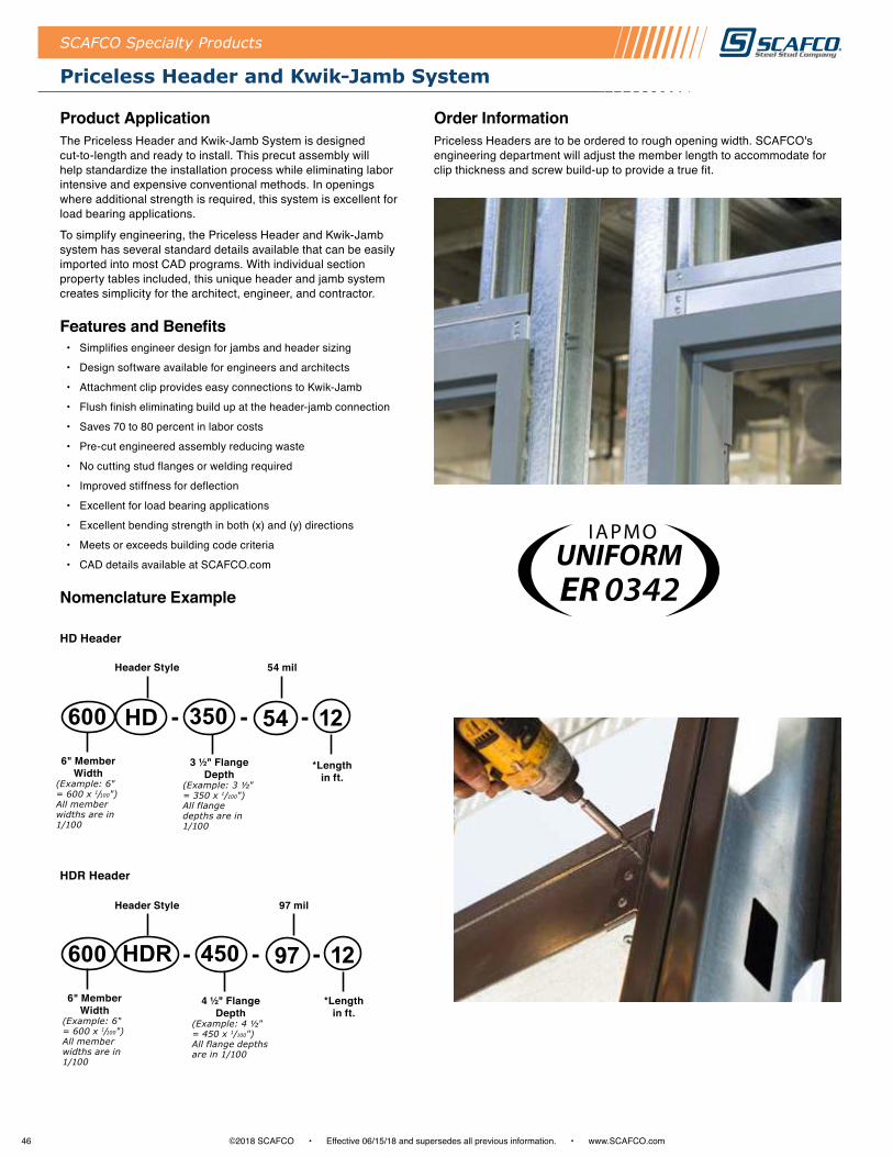
46 ©2018 SCAFCO • Effective 06/15/18 and supersedes all previous information . • www .SCAFCO .com
Priceless Header and Kwik-Jamb System
SCAFCO Specialty Products
Product ApplicationThe Priceless Header and Kwik-Jamb System is designed cut-to-length and ready to install . This precut assembly will help standardize the installation process while eliminating labor intensive and expensive conventional methods . In openings where additional strength is required, this system is excellent for load bearing applications .
To simplify engineering, the Priceless Header and Kwik-Jamb system has several standard details available that can be easily imported into most CAD programs . With individual section property tables included, this unique header and jamb system creates simplicity for the architect, engineer, and contractor .
Features and Benefits • Simplifies engineer design for jambs and header sizing
• Design software available for engineers and architects
• Attachment clip provides easy connections to Kwik-Jamb
• Flush finish eliminating build up at the header-jamb connection
• Saves 70 to 80 percent in labor costs
• Pre-cut engineered assembly reducing waste
• No cutting stud flanges or welding required
• Improved stiffness for deflection
• Excellent for load bearing applications
• Excellent bending strength in both (x) and (y) directions
• Meets or exceeds building code criteria
• CAD details available at SCAFCO .com
Nomenclature Example
HD Header
HDR Header
350HD600 54 12
Header Style
Header Style
54 mil
97 mil
3 ½" Flange Depth
(Example: 3 ½" = 350 x 1/100") All flange depths are in 1/100
6" Member Width
(Example: 6" = 600 x 1/100") All member widths are in 1/100
*Length in ft .
-- -
450HDR600 97 12
4 ½" Flange Depth
(Example: 4 ½" = 450 x 1/100") All flange depths are in 1/100
6" Member Width
(Example: 6" = 600 x 1/100") All member widths are in 1/100
*Length in ft .
-- -
Order InformationPriceless Headers are to be ordered to rough opening width . SCAFCO's engineering department will adjust the member length to accommodate for clip thickness and screw build-up to provide a true fit .
ER 0342
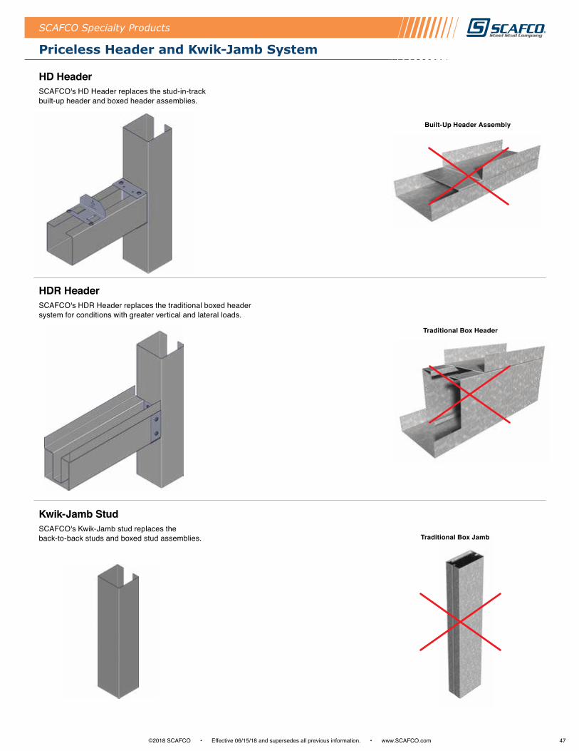
47©2018 SCAFCO • Effective 06/15/18 and supersedes all previous information . • www .SCAFCO .com
Priceless Header and Kwik-Jamb System
SCAFCO Specialty Products
Built-Up Header Assembly
Traditional Box Header
HD HeaderSCAFCO's HD Header replaces the stud-in-track built-up header and boxed header assemblies .
HDR HeaderSCAFCO's HDR Header replaces the traditional boxed header system for conditions with greater vertical and lateral loads .
Kwik-Jamb StudSCAFCO's Kwik-Jamb stud replaces the back-to-back studs and boxed stud assemblies . Traditional Box Jamb
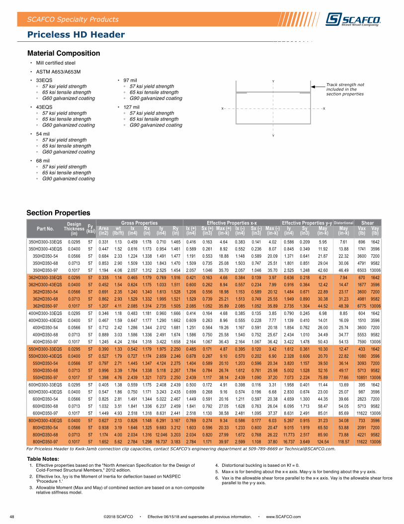
48 ©2018 SCAFCO • Effective 06/15/18 and supersedes all previous information . • www .SCAFCO .com
SCAFCO Specialty Products
Priceless HD Header
Section Properties
Part No.Design
Thickness (in)
Fy (ksi)
Gross Properties Effective Properties x-x Effective Properties y-y Distortional ShearArea (in2)
wt (lb/ft)
Ix (in4)
Rx (in)
Iy (in4)
Ry (in)
Ix (+) (in4)
Sx (+) (in3)
Max (+) (in-k)
Ix (-) (in4)
Sx (-) (in3)
Max (-) (in-k)
Iy (in4)
Sy (in3)
May (in-k)
May (in-k)
Vax (lb)
Vay (lb)
350HD300-33EQS 0.0295 57 0.331 1.13 0.459 1.178 0.710 1.465 0.416 0.163 4.64 0.383 0.141 4.02 0.586 0.209 5.95 7.61 696 1642350HD300-43EQS 0.0400 57 0.447 1.52 0.616 1.173 0.954 1.461 0.589 0.261 8.92 0.552 0.236 8.07 0.845 0.349 11.92 13.88 1741 3596
350HD350-54 0.0566 57 0.684 2.33 1.224 1.338 1.491 1.477 1.191 0.553 18.88 1.148 0.589 20.09 1.371 0.641 21.87 22.32 3600 7200350HD350-68 0.0713 57 0.853 2.90 1.509 1.330 1.843 1.470 1.509 0.735 25.08 1.503 0.747 25.51 1.801 0.851 29.04 30.06 4791 9582350HD350-97 0.1017 57 1.194 4.06 2.057 1.312 2.525 1.454 2.057 1.046 35.70 2.057 1.046 35.70 2.525 1.248 42.60 46.49 6503 13006
362HD300-33EQS 0.0295 57 0.335 1.14 0.465 1.179 0.769 1.516 0.421 0.163 4.66 0.384 0.139 3.97 0.636 0.218 6.21 7.94 670 1642362HD300-43EQS 0.0400 57 0.452 1.54 0.624 1.175 1.033 1.511 0.600 0.262 8.94 0.557 0.234 7.99 0.916 0.364 12.42 14.47 1677 3596
362HD350-54 0.0566 57 0.691 2.35 1.240 1.340 1.613 1.528 1.206 0.556 18.98 1.153 0.589 20.12 1.484 0.671 22.89 23.17 3600 7200362HD350-68 0.0713 57 0.862 2.93 1.529 1.332 1.995 1.521 1.529 0.739 25.21 1.513 0.749 25.55 1.949 0.890 30.38 31.23 4981 9582362HD350-97 0.1017 57 1.207 4.11 2.085 1.314 2.735 1.505 2.085 1.052 35.89 2.085 1.052 35.89 2.735 1.304 44.52 48.39 6775 13006
400HD300-33EQS 0.0295 57 0.346 1.18 0.483 1.181 0.960 1.666 0.414 0.164 4.68 0.385 0.135 3.85 0.790 0.245 6.98 8.85 604 1642400HD300-43EQS 0.0400 57 0.467 1.59 0.647 1.177 1.290 1.662 0.609 0.263 8.96 0.555 0.228 7.77 1.139 0.410 14.01 16.09 1510 3596
400HD350-54 0.0566 57 0.712 2.42 1.286 1.344 2.012 1.681 1.251 0.564 19.26 1.167 0.591 20.18 1.854 0.762 26.00 25.74 3600 7200400HD350-68 0.0713 57 0.889 3.03 1.586 1.336 2.491 1.674 1.586 0.750 25.58 1.540 0.752 25.67 2.434 1.010 34.49 34.77 5553 9582400HD350-97 0.1017 57 1.245 4.24 2.164 1.318 3.422 1.658 2.164 1.067 36.43 2.164 1.067 36.42 3.422 1.478 50.43 54.13 7590 13006
550HD300-33EQS 0.0295 57 0.390 1.33 0.542 1.179 1.975 2.250 0.485 0.171 4.87 0.395 0.120 3.42 1.612 0.361 10.30 12.47 433 1642550HD300-43EQS 0.0400 57 0.527 1.79 0.727 1.174 2.659 2.246 0.678 0.267 9.10 0.570 0.202 6.90 2.328 0.606 20.70 22.82 1080 3596
550HD350-54 0.0566 57 0.797 2.71 1.445 1.347 4.124 2.275 1.404 0.589 20.10 1.203 0.596 20.34 3.820 1.157 39.50 36.14 3093 7200550HD350-68 0.0713 57 0.996 3.39 1.784 1.338 5.118 2.267 1.784 0.784 26.74 1.612 0.761 25.98 5.002 1.528 52.16 49.17 5713 9582550HD350-97 0.1017 57 1.398 4.76 2.439 1.321 7.073 2.250 2.439 1.117 38.14 2.439 1.090 37.20 7.073 2.224 75.89 77.66 10851 13006
600HD300-33EQS 0.0295 57 0.405 1.38 0.559 1.175 2.408 2.439 0.500 0.172 4.91 0.398 0.116 3.31 1.958 0.401 11.44 13.69 395 1642600HD300-43EQS 0.0400 57 0.547 1.86 0.750 1.171 3.243 2.435 0.699 0.268 9.16 0.574 0.196 6.68 2.830 0.674 23.00 25.07 987 3596
600HD350-54 0.0566 57 0.825 2.81 1.491 1.344 5.022 2.467 1.449 0.591 20.16 1.211 0.597 20.38 4.659 1.300 44.35 39.66 2823 7200600HD350-68 0.0713 57 1.032 3.51 1.841 1.336 6.237 2.459 1.841 0.792 27.05 1.628 0.763 26.04 6.095 1.713 58.47 54.05 5713 9582600HD350-97 0.1017 57 1.449 4.93 2.518 1.318 8.631 2.441 2.518 1.130 38.58 2.481 1.095 37.37 8.631 2.491 85.01 85.69 11622 13006
800HD300-43EQS 0.0400 57 0.627 2.13 0.826 1.148 6.291 3.167 0.769 0.274 9.34 0.586 0.177 6.03 5.267 0.915 31.23 34.08 733 3596800HD350-54 0.0566 57 0.938 3.19 1.646 1.325 9.683 3.212 1.603 0.596 20.33 1.233 0.600 20.47 9.015 1.919 65.50 53.88 2091 7200800HD350-68 0.0713 57 1.174 4.00 2.034 1.316 12.046 3.203 2.034 0.820 27.99 1.672 0.768 26.22 11.773 2.517 85.90 73.88 4221 9582800HD350-97 0.1017 57 1.652 5.62 2.784 1.298 16.737 3.183 2.784 1.171 39.97 2.599 1.108 37.80 16.737 3.649 124.54 118.57 11622 13006
Table Notes:1 . Effective properties based on the "North American Specification for the Design of
Cold-Formed Structural Members," 2012 edition .2 . Effective Ixx, Iyy is the Moment of Inertia for deflection based on NASPEC
'Procedure 1 .'3 . Allowable Moment (Max and May) of combined section are based on a non-composite
relative stiffness model .
4 . Distortional buckling is based on Kf = 0 .5 . Max-x is for bending about the x-x axis . May-y is for bending about the y-y axis .6 . Vax is the allowable shear force parallel to the x-x axis . Vay is the allowable shear force
parallel to the y-y axis .
For Priceless Header to Kwik-Jamb connection clip capacities, contact SCAFCO's engineering department at 509-789-8669 or [email protected].
Material Composition• Mill certified steel
• ASTM A653/A653M• 33EQS
◦ 57 ksi yield strength ◦ 65 ksi tensile strength ◦ G60 galvanized coating
• 43EQS ◦ 57 ksi yield strength ◦ 65 ksi tensile strength ◦ G60 galvanized coating
• 54 mil ◦ 57 ksi yield strength ◦ 65 ksi tensile strength ◦ G60 galvanized coating
• 68 mil ◦ 57 ksi yield strength ◦ 65 ksi tensile strength ◦ G90 galvanized coating
• 97 mil ◦ 57 ksi yield strength ◦ 65 ksi tensile strength ◦ G90 galvanized coating
• 127 mil ◦ 57 ksi yield strength ◦ 65 ksi tensile strength ◦ G90 galvanized coating
Y
Y
XX
Y
Y
XX
Y
Y
XX
Track strength not included in the section properties

49©2018 SCAFCO • Effective 06/15/18 and supersedes all previous information . • www .SCAFCO .com
Priceless HDR Header
SCAFCO Specialty Products
Section Properties
Part No.Design
Thickness (in)
Fy (ksi)
Gross Properties Effective Properties x-x Effective Properties y-y Distortional ShearArea (in2)
wt (lb/ft)
Ix (in4)
Rx (in)
Iy (in4)
Ry (in)
Ix (+) (in4)
Sx (+) (in3)
Max (+) (in-k)
Ix (-) (in4)
Sx (-) (in3)
Max (-) (in-k)
Iy (in4)
Sy (in3)
May (in-k)
May (in-k)
Vax (lb)
Vay (lb)
350HDR200-33EQS 0.0295 57 0.541 1.842 0.419 0.880 0.854 1.256 0.321 0.150 5.1 0.389 0.226 7.72 0.707 0.340 11.59 11.75 1195 4330350HDR350-54 0.0566 57 1.368 4.654 2.597 1.378 2.146 1.253 2.514 0.907 31.0 2.599 1.080 36.87 1.944 0.913 31.15 31.55 5519 15712350HDR350-68 0.0713 57 1.710 5.817 3.205 1.369 2.658 1.247 3.242 1.201 41.0 3.284 1.372 46.83 2.492 1.183 40.39 42.82 7097 21837350HDR350-97 0.1017 57 2.400 8.165 4.375 1.350 3.660 1.235 4.510 1.889 64.5 4.510 1.889 64.49 3.548 1.774 60.56 65.10 9614 30185
362HDR200-33EQS 0.0295 57 0.549 1.868 0.430 0.885 0.933 1.304 0.329 0.152 5.2 0.402 0.231 7.88 0.777 0.360 12.30 12.46 1161 4378362HDR350-54 0.0566 57 1.382 4.702 2.650 1.385 2.345 1.303 2.564 0.917 31.3 2.642 1.087 37.09 2.133 0.967 32.99 33.14 5580 15812362HDR350-68 0.0713 57 1.727 5.878 3.270 1.376 2.906 1.297 3.307 1.215 41.5 3.351 1.386 47.32 2.731 1.253 42.75 45.00 7470 21981362HDR350-97 0.1017 57 2.425 8.252 4.468 1.357 4.003 1.285 4.606 1.930 65.9 4.606 1.930 65.87 3.889 1.876 64.02 69.05 10132 30022
400HDR200-33EQS 0.0295 57 0.571 1.943 0.460 0.897 1.196 1.447 0.352 0.159 5.4 0.426 0.236 8.05 1.010 0.425 14.52 14.39 1070 4506400HDR350-54 0.0566 57 1.424 4.846 2.802 1.403 3.008 1.453 2.707 0.945 32.3 2.764 1.107 37.77 2.761 1.135 38.74 38.00 5749 16087400HDR350-68 0.0713 57 1.781 6.060 3.460 1.394 3.730 1.447 3.496 1.252 42.7 3.517 1.416 48.33 3.526 1.468 50.10 51.67 8605 21802400HDR350-97 0.1017 57 2.501 8.511 4.735 1.376 5.146 1.434 4.880 1.988 67.9 4.880 1.988 67.85 5.027 2.192 74.80 80.54 11713 29596
550HDR200-33EQS 0.0295 57 0.659 2.244 0.560 0.921 2.663 2.010 0.425 0.177 6.0 0.506 0.253 8.65 2.315 0.719 24.54 21.99 809 4637550HDR350-54 0.0566 57 1.594 5.424 3.328 1.445 6.692 2.049 3.203 1.032 35.2 3.179 1.165 39.76 6.247 1.882 64.25 58.03 5477 15540550HDR450-68 0.0713 57 2.280 7.758 7.220 1.779 9.692 2.062 7.236 2.055 70.1 7.061 2.199 75.04 8.842 2.498 85.24 83.46 9874 24432550HDR450-97 0.1017 57 3.213 10.934 9.976 1.762 13.456 2.046 10.199 3.202 109.3 10.199 3.202 109.29 12.800 3.780 129.02 132.53 18071 36991550HDR450-127 0.1337 57 4.170 14.191 12.675 1.743 17.185 2.030 13.040 4.130 141.0 13.040 4.130 140.97 16.831 5.189 177.10 184.98 22550 46189
600HDR200-33EQS 0.0295 57 0.689 2.344 0.588 0.924 3.313 2.193 0.445 0.181 6.2 0.528 0.258 8.80 2.896 0.828 28.27 24.54 748 4572600HDR350-54 0.0566 57 1.651 5.617 3.480 1.452 8.309 2.244 3.346 1.055 36.0 3.296 1.179 40.24 7.774 2.155 73.56 64.83 5073 15290600HDR450-68 0.0713 57 2.351 8.001 7.534 1.790 12.030 2.262 7.547 2.097 71.6 7.304 2.223 75.88 10.992 2.865 97.80 93.31 10071 24048600HDR450-97 0.1017 57 3.315 11.280 10.419 1.773 16.724 2.246 10.650 3.266 111.5 10.592 3.249 110.89 15.933 4.336 147.98 148.89 20283 36505600HDR450-127 0.1337 57 4.304 14.646 13.248 1.754 21.389 2.229 13.632 4.216 143.9 13.632 4.216 143.89 20.975 5.940 202.75 208.33 25468 45817
800HDR250-43EQS 0.04 57 1.173 3.990 1.418 1.100 10.158 2.943 1.205 0.415 14.2 1.274 0.512 17.46 9.322 1.984 67.71 55.02 1405 7554800HDR350-54 0.0566 57 1.877 6.387 3.996 1.459 16.912 3.002 3.831 1.124 38.3 3.689 1.220 41.66 15.905 3.355 114.52 92.48 3911 14578800HDR450-68 0.0713 57 2.637 8.971 8.624 1.809 24.410 3.043 8.621 2.229 76.1 8.131 2.295 78.33 22.386 4.487 153.15 133.38 7977 22907800HDR450-97 0.1017 57 3.722 12.664 11.950 1.792 34.065 3.025 12.209 3.468 118.4 11.877 3.373 115.14 32.582 6.781 231.44 216.29 21515 34910800HDR450-127 0.1337 57 4.839 16.466 15.228 1.774 43.750 3.007 15.676 4.482 153.0 15.676 4.482 152.98 43.028 9.231 315.07 305.28 36407 447631000HDR250-54 0.0566 57 1.877 6.387 2.165 1.074 24.835 3.637 2.052 0.674 23.0 2.017 0.767 26.18 24.228 4.482 152.99 114.68 3227 108381000HDR450-68 0.0713 57 2.922 9.942 9.502 1.803 42.063 3.794 9.485 2.322 79.3 8.782 2.342 79.92 38.673 6.333 216.15 174.07 6493 221591000HDR450-97 0.1017 57 4.129 14.048 13.181 1.787 58.850 3.775 13.463 3.608 123.2 12.871 3.450 117.74 56.424 9.554 326.09 285.79 19146 338141000HDR450-127 0.1337 57 5.374 18.286 16.816 1.769 75.789 3.755 17.317 4.667 159.3 17.085 4.605 157.17 74.641 12.941 441.70 406.41 37650 435151200HDR250-54 0.0566 57 2.103 7.157 2.321 1.051 39.181 4.316 2.194 0.693 23.7 2.142 0.780 26.64 38.367 5.565 189.96 139.23 2711 106351200HDR450-68 0.0713 57 3.207 10.912 10.225 1.786 65.559 4.521 10.196 2.391 81.6 9.313 2.374 81.04 60.471 8.398 286.64 214.95 5471 216341200HDR450-97 0.1017 57 4.535 15.433 14.193 1.769 91.891 4.501 14.494 3.712 126.7 13.669 3.501 119.50 88.271 12.634 431.22 356.18 16121 330231200HDR450-127 0.1337 57 5.909 20.105 18.120 1.751 118.575 4.480 18.663 4.804 164.0 18.199 4.684 159.88 116.884 17.045 581.79 510.06 36349 42568
Table Notes:1 . Effective properties based on the "North American Specification for the Design of
Cold-Formed Structural Members," 2012 edition .2 . Effective Ixx, Iyy is the Moment of Inertia for deflection based on NASPEC
'Procedure 1 .'3 . Allowable Moment (Max and May) of combined section are based on a non-composite
relative stiffness model .
4 . Distortional buckling is based on Kf = 0 .5 . Max-x is for bending about the x-x axis . May-y is for bending about the y-y axis .6 . Vax is the allowable shear force parallel to the x-x axis . Vay is the allowable shear force
parallel to the y-y axis .
For Priceless Header to Kwik-Jamb connection clip capacities, contact SCAFCO's engineering department at 509-789-8669 or [email protected].
Y
Y
XX
Y
Y
XX
Y
Y
XX
Material Composition• Mill certified steel
• ASTM A653/A653M
• 33EQS ◦ 57 ksi yield strength ◦ 65 ksi tensile strength ◦ G60 galvanized coating
• 43EQS ◦ 57 ksi yield strength ◦ 65 ksi tensile strength ◦ G60 galvanized coating
• 54 mil ◦ 57 ksi yield strength ◦ 65 ksi tensile strength ◦ G60 galvanized coating
• 68 mil ◦ 57 ksi yield strength ◦ 65 ksi tensile strength ◦ G90 galvanized coating
• 97 mil ◦ 57 ksi yield strength ◦ 65 ksi tensile strength ◦ G90 galvanized coating
• 127 mil ◦ 57 ksi yield strength ◦ 65 ksi tensile strength ◦ G90 galvanized coating
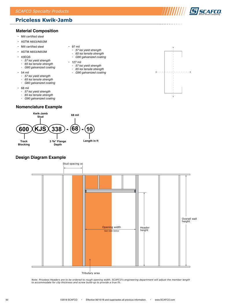
50 ©2018 SCAFCO • Effective 06/15/18 and supersedes all previous information . • www .SCAFCO .com
SCAFCO Specialty Products
Priceless Kwik-Jamb
Material Composition• Mill certified steel
• ASTM A653/A653M• Mill certified steel
• ASTM A653/A653M
• 43EQS ◦ 57 ksi yield strength ◦ 65 ksi tensile strength ◦ G60 galvanized coating
• 54 mil ◦ 57 ksi yield strength ◦ 65 ksi tensile strength ◦ G60 galvanized coating
• 68 mil ◦ 57 ksi yield strength ◦ 65 ksi tensile strength ◦ G90 galvanized coating
• 97 mil ◦ 57 ksi yield strength ◦ 65 ksi tensile strength ◦ G90 galvanized coating
• 127 mil ◦ 57 ksi yield strength ◦ 65 ksi tensile strength ◦ G90 galvanized coating
338KJS600 68 10
Kwik-Jamb Stud 68 mil
3 ⅜" Flange Depth
Track Blocking
Length in ft
- -
Nomenclature Example
Design Diagram Example
Opening widthSee note below
Tributary area
Stud spacing oc
Headerheight
Overall wallheight
Note: Priceless Headers are to be ordered to rough opening width. SCAFCO's engineering department will adjust the member length to accommodate for clip thickness and screw build-up to provide a true fit.
Y
Y
XX
Y
Y
XX
Y
Y
XX
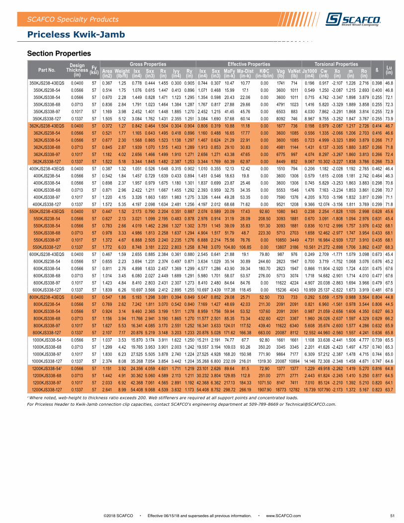
51©2018 SCAFCO • Effective 06/15/18 and supersedes all previous information . • www .SCAFCO .com
Priceless Kwik-Jamb
SCAFCO Specialty Products
Part No.Design
Thickness (in)
Fy (ksi)
Gross Properties Effective Properties Torsional Propertiesß Lu
(in)Area (in2)
Weight (lb/ft)
Ixx (in4)
Sxx (in3)
Rx (in)
Iyy (in4)
Ry (in)
Ixx (in4)
Sxx (in3)
MaFy (in-k)
Ma-Dist (in-k)
KΦC (in-lb/in)
Vag (lb)
VaNet (lb)
Jx1000 (in4)
Cw (in6)
Xo (in)
m (in)
Ro (in)
350KJS238-43EQS 0.0400 57 0.367 1.25 0.778 0.444 1.455 0.300 0.905 0.744 0.307 10.47 10.77 0.00 1741 714 0.196 0.917 -2.107 1.226 2.716 0.398 46.8350KJS238-54 0.0566 57 0.514 1.75 1.076 0.615 1.447 0.413 0.896 1.071 0.468 15.99 17.1 0.00 3600 1011 0.549 1.250 -2.087 1.215 2.693 0.400 46.8350KJS338-54 0.0566 57 0.670 2.28 1.449 0.828 1.471 1.123 1.295 1.354 0.598 20.43 22.06 0.00 3600 1011 0.715 4.742 -3.347 1.898 3.879 0.255 72.1350KJS338-68 0.0713 57 0.836 2.84 1.791 1.023 1.464 1.384 1.287 1.767 0.817 27.88 29.66 0.00 4791 1023 1.416 5.820 -3.329 1.889 3.858 0.255 72.3350KJS338-97 0.1017 57 1.169 3.98 2.452 1.401 1.448 1.885 1.270 2.452 1.215 41.45 45.76 0.00 6503 883 4.030 7.862 -3.291 1.868 3.814 0.255 72.9350KJS338-127 0.1337 57 1.505 5.12 3.084 1.762 1.431 2.355 1.251 3.084 1.690 57.68 60.14 0.00 8092 746 8.967 9.755 -3.252 1.847 3.767 0.255 73.9
362KJS238-43EQS 0.0400 57 0.372 1.27 0.842 0.464 1.504 0.304 0.904 0.806 0.319 10.88 11.18 0.00 1677 736 0.198 0.979 -2.087 1.217 2.726 0.414 46.7362KJS238-54 0.0566 57 0.521 1.77 1.165 0.643 1.495 0.418 0.896 1.160 0.488 16.65 17.77 0.00 3600 1085 0.556 1.335 -2.066 1.206 2.703 0.416 46.6362KJS338-54 0.0566 57 0.677 2.30 1.568 0.865 1.523 1.138 1.297 1.467 0.624 21.29 22.91 0.00 3600 1085 0.723 4.999 -3.323 1.890 3.879 0.266 71.7362KJS338-68 0.0713 57 0.845 2.87 1.939 1.070 1.515 1.403 1.289 1.913 0.853 29.10 30.83 0.00 4981 1144 1.431 6.137 -3.305 1.880 3.857 0.266 71.8362KJS338-97 0.1017 57 1.182 4.02 2.656 1.466 1.499 1.910 1.271 2.656 1.271 43.38 47.65 0.00 6775 997 4.074 8.297 -3.267 1.860 3.813 0.266 72.4362KJS338-127 0.1337 57 1.522 5.18 3.344 1.845 1.482 2.387 1.253 3.344 1.769 60.39 62.97 0.00 8449 852 9.067 10.302 -3.227 1.838 3.766 0.266 73.3
400KJS238-43EQS 0.0400 57 0.387 1.32 1.051 0.526 1.648 0.315 0.902 1.010 0.355 12.13 12.42 0.00 1510 794 0.206 1.182 -2.028 1.192 2.765 0.462 46.4400KJS238-54 0.0566 57 0.542 1.84 1.457 0.729 1.639 0.433 0.894 1.451 0.546 18.63 19.8 0.00 3600 1306 0.579 1.615 -2.008 1.181 2.742 0.464 46.3400KJS338-54 0.0566 57 0.698 2.37 1.957 0.979 1.675 1.180 1.301 1.837 0.699 23.87 25.46 0.00 3600 1306 0.745 5.829 -3.253 1.863 3.883 0.298 70.6400KJS338-68 0.0713 57 0.871 2.96 2.422 1.211 1.667 1.455 1.292 2.393 0.959 32.75 34.35 0.00 5553 1546 1.476 7.163 -3.234 1.853 3.861 0.298 70.7400KJS338-97 0.1017 57 1.220 4.15 3.326 1.663 1.651 1.983 1.275 3.326 1.444 49.28 53.35 0.00 7590 1376 4.205 9.703 -3.196 1.832 3.817 0.299 71.1400KJS338-127 0.1337 57 1.572 5.35 4.197 2.098 1.634 2.481 1.256 4.197 2.012 68.68 71.62 0.00 9521 1208 9.366 12.074 -3.156 1.811 3.769 0.299 71.8
550KJS238-43EQS 0.0400 57 0.447 1.52 2.173 0.790 2.204 0.351 0.887 2.074 0.589 20.09 17.43 92.60 1080 943 0.238 2.254 -1.828 1.105 2.998 0.628 45.6550KJS238-54 0.0566 57 0.627 2.13 3.021 1.099 2.195 0.483 0.878 2.976 0.914 31.19 28.09 208.50 3093 1881 0.670 3.091 -1.808 1.094 2.976 0.631 45.4550KJS338-54 0.0566 57 0.783 2.66 4.019 1.462 2.266 1.327 1.302 3.751 1.145 39.09 35.83 151.30 3093 1881 0.836 10.112 -2.996 1.757 3.976 0.432 68.1550KJS338-68 0.0713 57 0.978 3.33 4.986 1.813 2.258 1.637 1.294 4.904 1.517 51.79 48.7 223.30 5713 2703 1.658 12.462 -2.977 1.747 3.954 0.433 68.1550KJS338-97 0.1017 57 1.372 4.67 6.888 2.505 2.240 2.235 1.276 6.888 2.214 75.56 76.76 0.00 10850 3449 4.731 16.984 -2.939 1.727 3.910 0.435 68.1550KJS338-127 0.1337 57 1.772 6.03 8.748 3.181 2.222 2.803 1.258 8.748 3.070 104.80 106.85 0.00 13807 3186 10.561 21.272 -2.898 1.706 3.862 0.437 68.3
600KJS238-43EQS 0.0400 57 0.467 1.59 2.655 0.885 2.384 0.361 0.880 2.545 0.641 21.88 19.1 79.80 987 976 0.249 2.709 -1.771 1.079 3.098 0.673 45.4600KJS238-54 0.0566 57 0.655 2.23 3.694 1.231 2.374 0.497 0.871 3.634 1.029 35.14 30.89 244.60 2823 1947 0.700 3.719 -1.752 1.068 3.076 0.676 45.2600KJS338-54 0.0566 57 0.811 2.76 4.898 1.633 2.457 1.369 1.299 4.577 1.286 43.90 39.34 180.70 2823 1947 0.866 11.904 -2.920 1.724 4.031 0.475 67.6600KJS338-68 0.0713 57 1.014 3.45 6.080 2.027 2.449 1.689 1.291 5.980 1.701 58.07 53.57 276.00 5713 3074 1.718 14.682 -2.901 1.714 4.010 0.477 67.6600KJS338-97 0.1017 57 1.423 4.84 8.410 2.803 2.431 2.307 1.273 8.410 2.480 84.64 84.76 0.00 11622 4224 4.907 20.038 -2.863 1.694 3.966 0.479 67.5600KJS338-127 0.1337 57 1.839 6.26 10.697 3.566 2.412 2.895 1.255 10.697 3.439 117.38 118.45 0.00 15236 4043 10.959 25.137 -2.822 1.673 3.919 0.481 67.6
800KJS238-43EQS 0.0400 57 0.547 1.86 5.193 1.298 3.081 0.394 0.849 5.047 0.852 29.08 25.71 52.50 733 733 0.292 5.059 -1.579 0.988 3.564 0.804 44.8800KJS238-54 0.0566 57 0.769 2.62 7.242 1.811 3.070 0.542 0.840 7.169 1.427 48.69 42.03 211.30 2091 2091 0.821 6.960 -1.561 0.978 3.544 0.806 44.5800KJS338-54 0.0566 57 0.924 3.14 9.460 2.365 3.199 1.511 1.278 8.959 1.756 59.94 53.52 137.60 2091 2091 0.987 21.059 -2.656 1.606 4.350 0.627 66.3800KJS338-68 0.0713 57 1.156 3.94 11.766 2.941 3.190 1.865 1.270 11.577 2.501 85.35 73.34 432.60 4221 3367 1.960 26.026 -2.637 1.597 4.329 0.629 66.2800KJS338-97 0.1017 57 1.627 5.53 16.341 4.085 3.170 2.551 1.252 16.341 3.633 124.01 117.52 439.40 11622 6340 5.608 35.674 -2.600 1.577 4.286 0.632 65.9800KJS338-127 0.1337 57 2.107 7.17 20.876 5.219 3.148 3.203 1.233 20.876 5.028 171.62 166.38 663.00 20087 8112 12.552 44.960 -2.560 1.557 4.241 0.636 65.81000KJS338-54 0.0566 57 1.037 3.53 15.870 3.174 3.911 1.622 1.250 15.211 2.191 74.77 67.7 92.80 1661 1661 1.108 33.638 -2.441 1.506 4.777 0.739 65.51000KJS338-68 0.0713 57 1.299 4.42 19.765 3.953 3.901 2.003 1.242 19.557 3.194 109.03 93.26 350.20 3345 3345 2.201 41.626 -2.423 1.497 4.757 0.740 65.31000KJS338-97 0.1017 57 1.830 6.23 27.525 5.505 3.878 2.740 1.224 27.525 4.928 168.20 150.98 771.90 9864 7177 6.309 57.212 -2.387 1.478 4.715 0.744 65.01000KJS338-127 0.1337 57 2.374 8.08 35.268 7.054 3.854 3.442 1.204 35.268 6.800 232.09 216.01 1319.30 20087 10894 14.146 72.308 -2.348 1.458 4.671 0.747 64.61200KJS338-541 0.0566 57 1.151 3.92 24.356 4.059 4.601 1.711 1.219 23.101 2.626 89.64 81.5 72.90 1377 1377 1.229 49.918 -2.262 1.419 5.270 0.816 64.81200KJS338-68 0.0713 57 1.442 4.91 30.362 5.060 4.589 2.113 1.211 30.232 3.804 129.85 112.8 251.00 2771 2771 2.443 61.824 -2.245 1.410 5.250 0.817 64.51200KJS338-97 0.1017 57 2.033 6.92 42.368 7.061 4.565 2.891 1.192 42.368 6.362 217.13 184.33 1071.50 8147 7411 7.010 85.124 -2.210 1.392 5.210 0.820 64.11200KJS338-127 0.1337 57 2.641 8.99 54.408 9.068 4.539 3.632 1.173 54.408 8.752 298.72 266.19 1907.90 18773 12782 15.739 107.790 -2.173 1.372 5.167 0.823 63.7
Section Properties
1 Where noted, web-height to thickness ratio exceeds 200. Web stiffeners are required at all support points and concentrated loads.For Priceless Header to Kwik-Jamb connection clip capacities, contact SCAFCO's engineering department at 509-789-8669 or [email protected].

52 ©2018 SCAFCO • Effective 06/15/18 and supersedes all previous information . • www .SCAFCO .com
SCAFCO Specialty Products
Perfect Curve™ Products
Product Application• High-quality and time saving
• Guaranteed accuracy through CAD software, designed and manufactured directly from project plans
• Assembled with steel rivets or welding; reducing built-in stresses
• Eliminates field modified standard framing members; no more flat spots or weak sections from field cutting and crimping
• Delivered ready to install
Features and Benefits • Curved products are fabricated from mill certified prime steel
and conform to all applicable ASTM specifications using precise, computer-controlled processes .
• Curved products are available in a variety of thicknesses, from 30mil to 97 mil .
• SCAFCO promises a perfect curved wall with structural strength and no flat spots .
• SCAFCO offers quick installation which will decrease layout time, considerably reducing your project schedule .
◦ Once Perfect Curve Products are delivered, simply set them in place and anchor them down.
◦ Perfect Curve eliminates labor-intensive crimping or cutting of the track at job sites.
◦ Match your curve's top and bottom track within 1/32 inch in 12 feet.
• Optional end tabs are available for splicing pieces together .
• When used in a structural application, the Perfect Curve products shall be reviewed and approved by the Architect or Engineer of record .
Material Composition• Mill certified steel• ASTM A653/A653M• 30 mil
◦ 33 ksi yield strength ◦ 45 ksi tensile strength ◦ G40 galvanized coating ◦ Steel rivet assembly only
• 33 mil ◦ 33 ksi yield strength ◦ 45 ksi tensile strength ◦ G60 galvanized coating ◦ Steel rivet assembly only
• 43 mil ◦ 33 ksi yield strength ◦ 45 ksi tensile strength ◦ G60 galvanized coating ◦ Steel rivet or welded assembly
• 54 mil ◦ 57 ksi yield strength ◦ 65 ksi tensile strength ◦ G60 galvanized coating ◦ Steel rivet or welded assembly
• 68 mil ◦ 57 ksi yield strength ◦ 65 ksi tensile strength ◦ G90 galvanized coating ◦ Steel rivet or welded assembly
• 97 mil ◦ 57 ksi yield strength ◦ 65 ksi tensile strength ◦ G90 galvanized coating ◦ Welded assembly only
Using Perfect-Curve Wall Products assures the architect's vision is delivered while saving the contractor an immense amount of time over traditional methods.

53©2018 SCAFCO • Effective 06/15/18 and supersedes all previous information . • www .SCAFCO .com
Perfect Curve™ Products
SCAFCO Specialty Products
Perfect Curve™ Wall Track Where curved walls and suspended walls are required, Perfect Curve is the best solution available today . Turning curved track on its side allows uses in domes and barreled ceilings, offering durability and ease of installation .
Perfect Curve™ Z-TrackWhere curved walls and suspended walls are required, Perfect Curve is the best solution available today . Turning curved track on its side allows uses in domes and barreled ceilings, offering durability and ease of installation .
Perfect Curve™ Slotted Track Built to accommodate vertical deflection in curved walls . Available in multiple radii with the option of larger slots for additional movement .
Perfect Curve™ Arch TrackDesigned for constructing arched openings, vaulted ceilings, and one-piece soffit faces in ceilings and extruded illuminated ceiling panes . *Shown as Arched Track Leg-Out
Perfect Curve™ Angle Intended for construction of smooth, curved soffit edges and dropped circular ceilings . *Shown as Curved Angle Leg-In
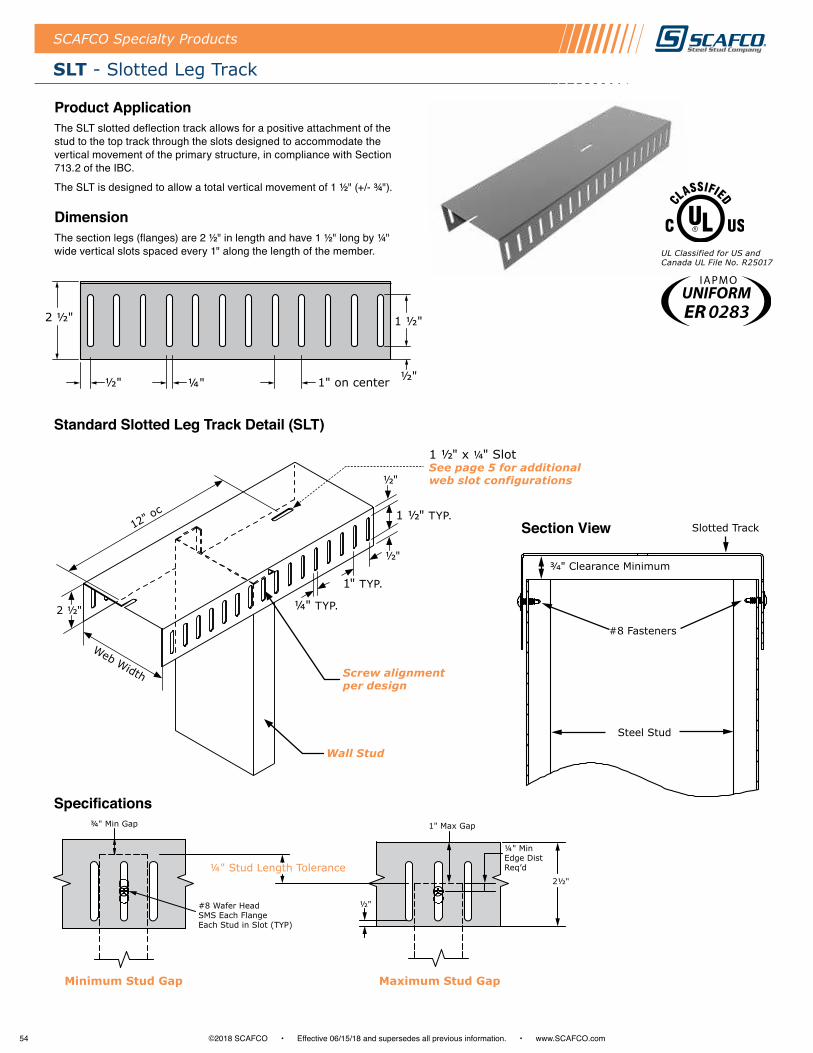
54 ©2018 SCAFCO • Effective 06/15/18 and supersedes all previous information . • www .SCAFCO .com
SCAFCO Specialty Products
SLT - Slotted Leg Track
Product ApplicationThe SLT slotted deflection track allows for a positive attachment of the stud to the top track through the slots designed to accommodate the vertical movement of the primary structure, in compliance with Section 713 .2 of the IBC .
The SLT is designed to allow a total vertical movement of 1 ½" (+/- ¾") .
DimensionThe section legs (flanges) are 2 ½" in length and have 1 ½" long by ¼" wide vertical slots spaced every 1" along the length of the member .
Slotted Track
#8 Fasteners
Steel Stud
Section View
UL Classified for US and Canada UL File No. R25017
2 ½"
½" ½"¼"
1 ½"
1" on center
Standard Slotted Leg Track Detail (SLT)
Specifications
12" oc
2 ½"
Web Width
Wall Stud
Screw alignment per design
¼" TYP.
1" TYP.
½"
½"
1 ½" TYP.
1 ½" x ¼" SlotSee page 5 for additional web slot configurations
¾" Min Gap
Minimum Stud Gap
1" Max Gap
¼" Stud Length Tolerance
#8 Wafer Head SMS Each Flange Each Stud in Slot (TYP)
½"
Maximum Stud Gap
¼" MinEdge DistReq’d
2½"
ER 0283
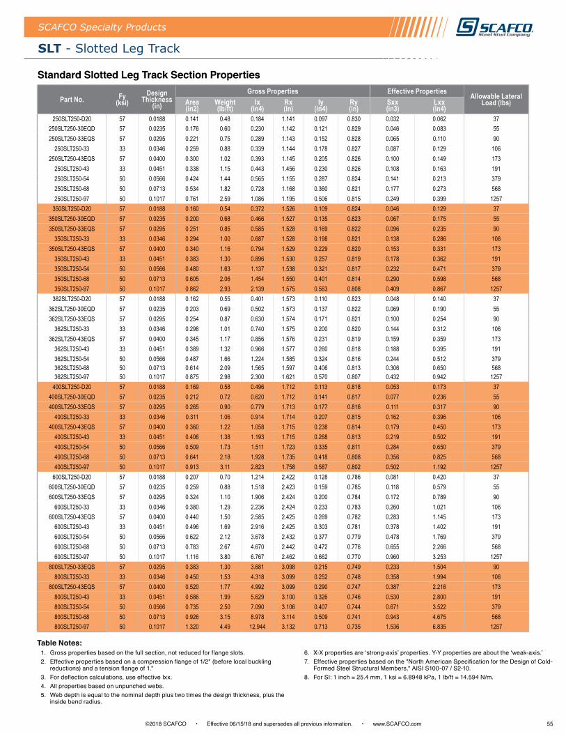
55©2018 SCAFCO • Effective 06/15/18 and supersedes all previous information . • www .SCAFCO .com
SLT - Slotted Leg Track
SCAFCO Specialty Products
Standard Slotted Leg Track Section Properties
Part No. Fy (ksi)
Design Thickness
(in)
Gross Properties Effective Properties Allowable Lateral Load (lbs)Area
(in2)Weight (lb/ft)
Ix (in4)
Rx (in)
Iy (in4)
Ry (in)
Sxx (in3)
Lxx (in4)
250SLT250-D20 57 0.0188 0.141 0.48 0.184 1.141 0.097 0.830 0.032 0.062 37250SLT250-30EQD 57 0.0235 0.176 0.60 0.230 1.142 0.121 0.829 0.046 0.083 55250SLT250-33EQS 57 0.0295 0.221 0.75 0.289 1.143 0.152 0.828 0.065 0.110 90
250SLT250-33 33 0.0346 0.259 0.88 0.339 1.144 0.178 0.827 0.087 0.129 106250SLT250-43EQS 57 0.0400 0.300 1.02 0.393 1.145 0.205 0.826 0.100 0.149 173
250SLT250-43 33 0.0451 0.338 1.15 0.443 1.456 0.230 0.826 0.108 0.163 191250SLT250-54 50 0.0566 0.424 1.44 0.565 1.155 0.287 0.824 0.141 0.213 379250SLT250-68 50 0.0713 0.534 1.82 0.728 1.168 0.360 0.821 0.177 0.273 568250SLT250-97 50 0.1017 0.761 2.59 1.086 1.195 0.506 0.815 0.249 0.399 1257
350SLT250-D20 57 0.0188 0.160 0.54 0.372 1.526 0.109 0.824 0.046 0.129 37350SLT250-30EQD 57 0.0235 0.200 0.68 0.466 1.527 0.135 0.823 0.067 0.175 55350SLT250-33EQS 57 0.0295 0.251 0.85 0.585 1.528 0.169 0.822 0.096 0.235 90
350SLT250-33 33 0.0346 0.294 1.00 0.687 1.528 0.198 0.821 0.138 0.286 106350SLT250-43EQS 57 0.0400 0.340 1.16 0.794 1.529 0.229 0.820 0.153 0.331 173
350SLT250-43 33 0.0451 0.383 1.30 0.896 1.530 0.257 0.819 0.178 0.362 191350SLT250-54 50 0.0566 0.480 1.63 1.137 1.538 0.321 0.817 0.232 0.471 379350SLT250-68 50 0.0713 0.605 2.06 1.454 1.550 0.401 0.814 0.290 0.598 568350SLT250-97 50 0.1017 0.862 2.93 2.139 1.575 0.563 0.808 0.409 0.867 1257
362SLT250-D20 57 0.0188 0.162 0.55 0.401 1.573 0.110 0.823 0.048 0.140 37362SLT250-30EQD 57 0.0235 0.203 0.69 0.502 1.573 0.137 0.822 0.069 0.190 55362SLT250-33EQS 57 0.0295 0.254 0.87 0.630 1.574 0.171 0.821 0.100 0.254 90
362SLT250-33 33 0.0346 0.298 1.01 0.740 1.575 0.200 0.820 0.144 0.312 106362SLT250-43EQS 57 0.0400 0.345 1.17 0.856 1.576 0.231 0.819 0.159 0.359 173
362SLT250-43 33 0.0451 0.389 1.32 0.966 1.577 0.260 0.818 0.188 0.395 191362SLT250-54 50 0.0566 0.487 1.66 1.224 1.585 0.324 0.816 0.244 0.512 379362SLT250-68 50 0.0713 0.614 2.09 1.565 1.597 0.406 0.813 0.306 0.650 568362SLT250-97 50 0.1017 0.875 2.98 2.300 1.621 0.570 0.807 0.432 0.942 1257
400SLT250-D20 57 0.0188 0.169 0.58 0.496 1.712 0.113 0.818 0.053 0.173 37400SLT250-30EQD 57 0.0235 0.212 0.72 0.620 1.712 0.141 0.817 0.077 0.236 55400SLT250-33EQS 57 0.0295 0.265 0.90 0.779 1.713 0.177 0.816 0.111 0.317 90
400SLT250-33 33 0.0346 0.311 1.06 0.914 1.714 0.207 0.815 0.162 0.396 106400SLT250-43EQS 57 0.0400 0.360 1.22 1.058 1.715 0.238 0.814 0.179 0.450 173
400SLT250-43 33 0.0451 0.406 1.38 1.193 1.715 0.268 0.813 0.219 0.502 191400SLT250-54 50 0.0566 0.509 1.73 1.511 1.723 0.335 0.811 0.284 0.650 379400SLT250-68 50 0.0713 0.641 2.18 1.928 1.735 0.418 0.808 0.356 0.825 568400SLT250-97 50 0.1017 0.913 3.11 2.823 1.758 0.587 0.802 0.502 1.192 1257
600SLT250-D20 57 0.0188 0.207 0.70 1.214 2.422 0.128 0.786 0.081 0.420 37600SLT250-30EQD 57 0.0235 0.259 0.88 1.518 2.423 0.159 0.785 0.118 0.579 55600SLT250-33EQS 57 0.0295 0.324 1.10 1.906 2.424 0.200 0.784 0.172 0.789 90
600SLT250-33 33 0.0346 0.380 1.29 2.236 2.424 0.233 0.783 0.260 1.021 106600SLT250-43EQS 57 0.0400 0.440 1.50 2.585 2.425 0.269 0.782 0.283 1.145 173
600SLT250-43 33 0.0451 0.496 1.69 2.916 2.425 0.303 0.781 0.378 1.402 191600SLT250-54 50 0.0566 0.622 2.12 3.678 2.432 0.377 0.779 0.478 1.769 379600SLT250-68 50 0.0713 0.783 2.67 4.670 2.442 0.472 0.776 0.655 2.266 568600SLT250-97 50 0.1017 1.116 3.80 6.767 2.462 0.662 0.770 0.960 3.253 1257
800SLT250-33EQS 57 0.0295 0.383 1.30 3.681 3.098 0.215 0.749 0.233 1.504 90800SLT250-33 33 0.0346 0.450 1.53 4.318 3.099 0.252 0.748 0.358 1.994 106
800SLT250-43EQS 57 0.0400 0.520 1.77 4.992 3.099 0.290 0.747 0.387 2.216 173800SLT250-43 33 0.0451 0.586 1.99 5.629 3.100 0.326 0.746 0.530 2.800 191800SLT250-54 50 0.0566 0.735 2.50 7.090 3.106 0.407 0.744 0.671 3.522 379800SLT250-68 50 0.0713 0.926 3.15 8.978 3.114 0.509 0.741 0.943 4.675 568800SLT250-97 50 0.1017 1.320 4.49 12.944 3.132 0.713 0.735 1.536 6.835 1257
1 . Gross properties based on the full section, not reduced for flange slots .2 . Effective properties based on a compression flange of 1/2" (before local buckling
reductions) and a tension flange of 1 ."3 . For deflection calculations, use effective Ixx . 4 . All properties based on unpunched webs . 5 . Web depth is equal to the nominal depth plus two times the design thickness, plus the
inside bend radius .
6 . X-X properties are ‘strong-axis’ properties. Y-Y properties are about the ‘weak-axis.’7 . Effective properties based on the "North American Specification for the Design of Cold-
Formed Steel Structural Members," AISI S100-07 / S2-10 . 8 . For SI: 1 inch = 25 .4 mm, 1 ksi = 6 .8948 kPa, 1 lb/ft = 14 .594 N/m .
Table Notes:
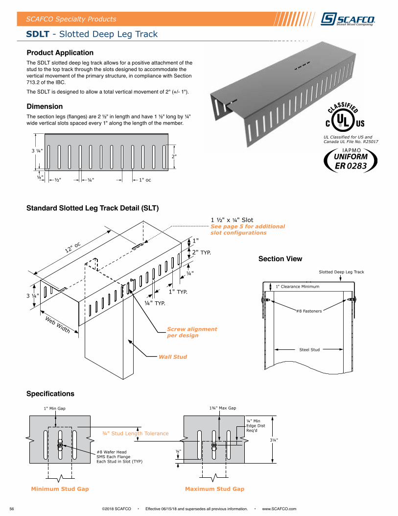
56 ©2018 SCAFCO • Effective 06/15/18 and supersedes all previous information . • www .SCAFCO .com
SCAFCO Specialty Products
SDLT - Slotted Deep Leg Track
UL Classified for US and Canada UL File No. R25017
3 ¼"
½"¼" ¼"
2"
1" oc
Product ApplicationThe SDLT slotted deep leg track allows for a positive attachment of the stud to the top track through the slots designed to accommodate the vertical movement of the primary structure, in compliance with Section 713 .2 of the IBC .
The SDLT is designed to allow a total vertical movement of 2" (+/- 1") .
DimensionThe section legs (flanges) are 2 ½" in length and have 1 ½" long by ¼" wide vertical slots spaced every 1" along the length of the member .
Section View
Standard Slotted Leg Track Detail (SLT)
Specifications
ER 0283
1" Min Gap
Minimum Stud Gap
1¾" Max Gap
¾" Stud Length Tolerance
#8 Wafer Head SMS Each Flange Each Stud in Slot (TYP)
¼"
Maximum Stud Gap
¼" MinEdge DistReq’d
3¼"
Slotted Deep Leg Track
#8 Fasteners
Steel Stud
1
Wall Stud
Screw alignment per design
12" oc
Web Width
3 ¼"¼" TYP.
1" TYP.
1"
¼"
2" TYP.
1 ½" x ¼" SlotSee page 5 for additional slot configurations
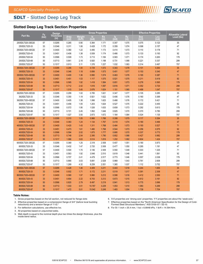
57©2018 SCAFCO • Effective 06/15/18 and supersedes all previous information . • www .SCAFCO .com
SDLT - Slotted Deep Leg Track
SCAFCO Specialty Products
Slotted Deep Leg Track Section Properties
Part No. Fy (ksi)
Design Thickness
(in)
Gross Properties Effective Properties Allowable Lateral Load (lbs)Area
(in2)Weight (lb/ft)
Ix (in4)
Rx (in)
Iy (in4)
Ry (in)
Sxx (in3)
Lxx (in4)
250SDLT325-33EQS 57 0.0295 0.265 0.90 0.364 1.171 0.307 1.075 0.075 0.123 35250SDLT325-33 33 0.0346 0.311 1.06 0.428 1.172 0.359 1.074 0.098 0.157 47
250SDLT325-43EQS 57 0.0400 0.360 1.22 0.495 1.173 0.414 1.073 0.110 0.178 71250SDLT325-43 33 0.0451 0.406 1.38 0.559 1.174 0.466 1.073 0.133 0.193 92250SDLT325-54 50 0.0566 0.509 1.73 0.713 1.184 0.583 1.071 0.174 0.263 179250SDLT325-68 50 0.0713 0.641 2.18 0.920 1.198 0.731 1.068 0.221 0.337 299250SDLT325-97 50 0.1017 0.913 3.11 1.376 1.227 1.032 1.063 0.314 0.497 707
350SDLT325-33EQS 57 0.0295 0.295 1.00 0.729 1.572 0.343 1.078 0.101 0.263 35350SDLT325-33 33 0.0346 0.346 1.18 0.856 1.573 0.401 1.077 0.153 0.340 47
350SDLT325-43EQS 57 0.0400 0.400 1.36 0.990 1.574 0.463 1.076 0.165 0.387 71350SDLT325-43 33 0.0451 0.451 1.53 1.117 1.575 0.521 1.075 0.211 0.419 92350SDLT325-54 50 0.0566 0.565 1.92 1.418 1.584 0.651 1.073 0.278 0.565 179350SDLT325-68 50 0.0713 0.712 2.42 1.816 1.597 0.816 1.071 0.352 0.720 299350SDLT325-97 50 0.1017 1.015 3.45 2.676 1.624 1.151 1.065 0.499 1.047 707
362SDLT325-33EQS 57 0.0295 0.299 1.02 0.785 1.621 0.347 1.077 0.105 0.285 35362SDLT325-33 33 0.0346 0.350 1.19 0.921 1.622 0.406 1.076 0.160 0.369 47
362SDLT325-43EQS 57 0.0400 0.405 1.38 1.066 1.623 0.468 1.076 0.172 0.421 71362SDLT325-43 33 0.0451 0.456 1.55 1.203 1.624 0.527 1.075 0.222 0.455 92362SDLT325-54 50 0.0566 0.572 1.95 1.526 1.633 0.659 1.073 0.292 0.613 179362SDLT325-68 50 0.0713 0.721 2.45 1.952 1.646 0.825 1.070 0.370 0.780 299362SDLT325-97 50 0.1017 1.027 3.50 2.873 1.672 1.164 1.064 0.524 1.135 707
400SDLT325-33EQS 57 0.0295 0.310 1.05 0.966 1.766 0.358 1.075 0.117 0.354 35400SDLT325-33 33 0.0346 0.363 1.24 1.134 1.767 0.419 1.074 0.180 0.466 47
400SDLT325-43EQS 57 0.0400 0.420 1.43 1.311 1.768 0.484 1.073 0.193 0.527 71400SDLT325-43 33 0.0451 0.473 1.61 1.480 1.768 0.544 1.073 0.256 0.575 92400SDLT325-54 50 0.0566 0.594 2.02 1.875 1.777 0.680 1.070 0.337 0.773 179400SDLT325-68 50 0.0713 0.748 2.54 2.395 1.790 0.852 1.068 0.427 0.982 299400SDLT325-97 50 0.1017 1.066 3.63 3.514 1.816 1.202 1.062 0.604 1.424 707
600SDLT325-33EQS 57 0.0295 0.369 1.25 2.319 2.508 0.407 1.051 0.180 0.873 35600SDLT325-33 33 0.0346 0.432 1.47 2.720 2.508 0.477 1.050 0.285 1.191 47
600SDLT325-43EQS 57 0.0400 0.500 1.70 3.146 2.509 0.550 1.049 0.303 1.325 71600SDLT325-43 33 0.0451 0.563 1.92 3.548 2.510 0.619 1.048 0.441 1.561 92600SDLT325-54 50 0.0566 0.707 2.41 4.479 2.517 0.773 1.046 0.557 2.038 179600SDLT325-68 50 0.0713 0.890 3.03 5.691 2.528 0.969 1.043 0.761 2.608 299600SDLT325-97 50 0.1017 1.269 4.32 8.259 2.551 1.365 1.037 1.112 3.752 707
800SDLT325-33EQS 57 0.0295 0.428 1.46 4.409 3.211 0.443 1.018 0.244 1.655 35800SDLT325-33 33 0.0346 0.502 1.71 5.172 3.211 0.519 1.017 0.391 2.308 47
800SDLT325-43EQS 57 0.0400 0.580 1.97 5.980 3.212 0.598 1.016 0.412 2.550 71800SDLT325-43 33 0.0451 0.654 2.22 6.743 3.212 0.673 1.015 0.612 3.161 92800SDLT325-54 50 0.0566 0.820 2.79 8.497 3.219 0.841 1.013 0.775 3.996 179800SDLT325-68 50 0.0713 1.033 3.51 10.767 3.229 1.053 1.010 1.083 5.269 299800SDLT325-97 50 0.1017 1.472 5.01 15.542 3.249 1.483 1.004 1.739 7.704 707
1 . Gross properties based on the full section, not reduced for flange slots2 . Effective properties based on a compression flange of 3/4" (before local buckling
reductions) and a tension flange of 1-1/2 ."3 . For deflection calculations, use effective Ixx . 4 . All properties based on unpunched webs . 5 . Web depth is equal to the nominal depth plus two times the design thickness, plus the
inside bend radius .
6 . X-X properties are ‘strong-axis’ properties. Y-Y properties are about the ‘weak-axis.’7 . Effective properties based on the "North American Specification for the Design of Cold-
Formed Steel Structural Members," AISI S100-07 / S2-10 .8 . For SI: 1 inch = 25 .4 mm, 1 ksi = 6 .8948 kPa, 1 lb/ft = 14 .594 N/m .
Table Notes:
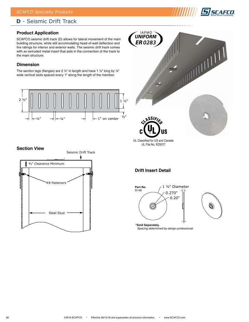
58 ©2018 SCAFCO • Effective 06/15/18 and supersedes all previous information . • www .SCAFCO .com
Seismic Drift Track
#8 Fasteners
Steel Stud
SCAFCO Specialty Products
D - Seismic Drift Track
Product ApplicationSCAFCO seismic drift track (D) allows for lateral movement of the main building structure, while still accomodating head-of-wall deflection and fire ratings for interior and exterior walls . The seismic drift track comes with an extruded metal insert that aids in the connection of the track to the main structure .
DimensionThe section legs (flanges) are 2 ½" in length and have 1 ½" long by ¼" wide vertical slots spaced every 1" along the length of the member .
Section View
Drift Insert Detail
UL Classified for US and Canada UL File No. R25017
ER 0283
2 ½"
½" ½"¼"
1 ½"
1" on center
Part No .DI-68
1 ½" Diameter
0.270"0.20"
*Sold Separately . Spacing determined by design professional.

59©2018 SCAFCO • Effective 06/15/18 and supersedes all previous information . • www .SCAFCO .com
D - Seismic Drift Track
SCAFCO Specialty Products
Section Properties
Part No. Fy (ksi)
Design Thickness
(in)
Gross Properties Effective Properties Allowable Lateral Load (lbs)Area
(in2)Weight (lb/ft)
Ix (in4)
Rx (in)
Iy (in4)
Ry (in)
Sxx (in3)
Lxx (in4)
250D250-D20 57 0.0188 0.141 0.48 0.184 1.141 0.097 0.83 0.032 0.062 37250D250-30EQD 57 0.0235 0.176 0.6 0.23 1.142 0.121 0.829 0.046 0.083 55250D250-33EQS 57 0.0295 0.221 0.75 0.289 1.143 0.152 0.828 0.065 0.11 90
250D250-33 33 0.0346 0.259 0.88 0.339 1.144 0.178 0.827 0.087 0.129 106250D250-43EQS 57 0.04 0.3 1.02 0.393 1.145 0.205 0.826 0.1 0.149 173
250D250-43 33 0.0451 0.338 1.15 0.443 1.456 0.23 0.826 0.108 0.163 191250D250-54 50 0.0566 0.424 1.44 0.565 1.155 0.287 0.824 0.141 0.213 379250D250-68 50 0.0713 0.534 1.82 0.728 1.168 0.36 0.821 0.177 0.273 568250D250-97 50 0.1017 0.761 2.59 1.086 1.195 0.506 0.815 0.249 0.399 1257
350D250-D20 57 0.0188 0.16 0.54 0.372 1.526 0.109 0.824 0.046 0.129 37350D250-30EQD 57 0.0235 0.2 0.68 0.466 1.527 0.135 0.823 0.067 0.175 55350D250-33EQS 57 0.0295 0.251 0.85 0.585 1.528 0.169 0.822 0.096 0.235 90
350D250-33 33 0.0346 0.294 1 0.687 1.528 0.198 0.821 0.138 0.286 106350D250-43EQS 57 0.04 0.34 1.16 0.794 1.529 0.229 0.82 0.153 0.331 173
350D250-43 33 0.0451 0.383 1.3 0.896 1.53 0.257 0.819 0.178 0.362 191350D250-54 50 0.0566 0.48 1.63 1.137 1.538 0.321 0.817 0.232 0.471 379350D250-68 50 0.0713 0.605 2.06 1.454 1.55 0.401 0.814 0.29 0.598 568350D250-97 50 0.1017 0.862 2.93 2.139 1.575 0.563 0.808 0.409 0.867 1257
362D250-D20 57 0.0188 0.162 0.55 0.401 1.573 0.11 0.823 0.048 0.14 37362D250-30EQD 57 0.0235 0.203 0.69 0.502 1.573 0.137 0.822 0.069 0.19 55362D250-33EQS 57 0.0295 0.254 0.87 0.63 1.574 0.171 0.821 0.1 0.254 90
362D250-33 33 0.0346 0.298 1.01 0.74 1.575 0.2 0.82 0.144 0.312 106362D250-43EQS 57 0.04 0.345 1.17 0.856 1.576 0.231 0.819 0.159 0.359 173
362D250-43 33 0.0451 0.389 1.32 0.966 1.577 0.26 0.818 0.188 0.395 191362D250-54 50 0.0566 0.487 1.66 1.224 1.585 0.324 0.816 0.244 0.512 379362D250-68 50 0.0713 0.614 2.09 1.565 1.597 0.406 0.813 0.306 0.65 568362D250-97 50 0.1017 0.875 2.98 2.3 1.621 0.57 0.807 0.432 0.942 1257
400D250-D20 57 0.0188 0.169 0.58 0.496 1.712 0.113 0.818 0.053 0.173 37400D250-30EQD 57 0.0235 0.212 0.72 0.62 1.712 0.141 0.817 0.077 0.236 55400D250-33EQS 57 0.0295 0.265 0.9 0.779 1.713 0.177 0.816 0.111 0.317 90
400D250-33 33 0.0346 0.311 1.06 0.914 1.714 0.207 0.815 0.162 0.396 106400D250-43EQS 57 0.04 0.36 1.22 1.058 1.715 0.238 0.814 0.179 0.45 173
400D250-43 33 0.0451 0.406 1.38 1.193 1.715 0.268 0.813 0.219 0.502 191400D250-54 50 0.0566 0.509 1.73 1.511 1.723 0.335 0.811 0.284 0.65 379400D250-68 50 0.0713 0.641 2.18 1.928 1.735 0.418 0.808 0.356 0.825 568400D250-97 50 0.1017 0.913 3.11 2.823 1.758 0.587 0.802 0.502 1.192 1257
600D250-D20 57 0.0188 0.207 0.7 1.214 2.422 0.128 0.786 0.081 0.42 37600D250-30EQD 57 0.0235 0.259 0.88 1.518 2.423 0.159 0.785 0.118 0.579 55600D250-33EQS 57 0.0295 0.324 1.1 1.906 2.424 0.2 0.784 0.172 0.789 90
600D250-33 33 0.0346 0.38 1.29 2.236 2.424 0.233 0.783 0.26 1.021 106600D250-43EQS 57 0.04 0.44 1.5 2.585 2.425 0.269 0.782 0.283 1.145 173
600D250-43 33 0.0451 0.496 1.69 2.916 2.425 0.303 0.781 0.378 1.402 191600D250-54 50 0.0566 0.622 2.12 3.678 2.432 0.377 0.779 0.478 1.769 379600D250-68 50 0.0713 0.783 2.67 4.67 2.442 0.472 0.776 0.655 2.266 568600D250-97 50 0.1017 1.116 3.8 6.767 2.462 0.662 0.77 0.96 3.253 1257
800D250-33EQS 57 0.0295 0.383 1.3 3.681 3.098 0.215 0.749 0.233 1.504 90800D250-33 33 0.0346 0.45 1.53 4.318 3.099 0.252 0.748 0.358 1.994 106
800D250-43EQS 57 0.04 0.52 1.77 4.992 3.099 0.29 0.747 0.387 2.216 173800D250-43 33 0.0451 0.586 1.99 5.629 3.1 0.326 0.746 0.53 2.8 191800D250-54 50 0.0566 0.735 2.5 7.09 3.106 0.407 0.744 0.671 3.522 379800D250-68 50 0.0713 0.926 3.15 8.978 3.114 0.509 0.741 0.943 4.675 568800D250-97 50 0.1017 1.32 4.49 12.944 3.132 0.713 0.735 1.536 6.835 1257
1 . Effective properties based on a compression flange of 1/2" (before local buckling reductions) and a tension flange of 1 ."
2 . For deflection calculations, use effective Ixx . 3 . All properties based on unpunched webs . 4 . Web depth is equal to the nominal depth plus two times the design thickness, plus the
inside bend radius .
5 . X-X properties are ‘strong-axis’ properties. Y-Y properties are about the ‘weak-axis.’6 . Effective properties based on the "North American Specification for the Design of Cold-
Formed Steel Structural Members," AISI S100-07 / S2-10 . 7 . For SI: 1 inch = 25 .4 mm, 1 ksi = 6 .8948 kPa, 1 lb/ft = 14 .594 N/m .
Table Notes:

60 ©2018 SCAFCO • Effective 06/15/18 and supersedes all previous information . • www .SCAFCO .com
SCAFCO Specialty Products
DD - Deep Leg Seismic Drift Track
Product ApplicationSCAFCO Deep Leg Seismic Drift Track (DD) allows for lateral movement of the main building structure, while still accomodating head-of-wall deflection and fire ratings for interior and exterior walls . The Deep Leg Seismic Drift Track comes with an extruded metal insert that aids in the connection of the track to the main structure .
DimensionThe section legs (flanges) are 3 ¼" in length and have 2" long by ¼" wide vertical slots spaced every 1" along the length of the member .
Section View
UL Classified for US and Canada UL File No. R25017
3 ¼"
½"¼" ¼"
2"
1" oc
Part No .DI-68
1 ½" Diameter
0.270"0.20"
Seismic Deep Leg Drift Track
#8 Fasteners
Steel Stud
1
Drift Insert Detail
*Sold Separately . Spacing determined by design professional.
ER 0283
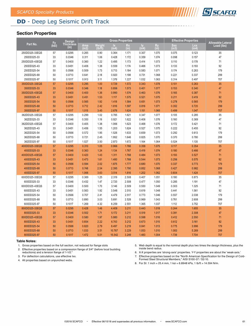
61©2018 SCAFCO • Effective 06/15/18 and supersedes all previous information . • www .SCAFCO .com
DD - Deep Leg Seismic Drift Track
SCAFCO Specialty Products
Section Properties
Part No. Fy (ksi)
Design Thickness
(in)
Gross Properties Effective Properties Allowable Lateral Load (lbs)Area
(in2)Weight (lb/ft)
Ix (in4)
Rx (in)
Iy (in4)
Ry (in)
Sxx (in3)
Lxx (in4)
250DD325-33EQS 57 0.0295 0.265 0.90 0.364 1.171 0.307 1.075 0.075 0.123 35250DD325-33 33 0.0346 0.311 1.06 0.428 1.172 0.359 1.074 0.098 0.157 47
250DD325-43EQS 57 0.0400 0.360 1.22 0.495 1.173 0.414 1.073 0.110 0.178 71250DD325-43 33 0.0451 0.406 1.38 0.559 1.174 0.466 1.073 0.133 0.193 92250DD325-54 50 0.0566 0.509 1.73 0.713 1.184 0.583 1.071 0.174 0.263 179250DD325-68 50 0.0713 0.641 2.18 0.920 1.198 0.731 1.068 0.221 0.337 299250DD325-97 50 0.1017 0.913 3.11 1.376 1.227 1.032 1.063 0.314 0.497 707
350DD325-33EQS 57 0.0295 0.295 1.00 0.729 1.572 0.343 1.078 0.101 0.263 35350DD325-33 33 0.0346 0.346 1.18 0.856 1.573 0.401 1.077 0.153 0.340 47
350DD325-43EQS 57 0.0400 0.400 1.36 0.990 1.574 0.463 1.076 0.165 0.387 71350DD325-43 33 0.0451 0.451 1.53 1.117 1.575 0.521 1.075 0.211 0.419 92350DD325-54 50 0.0566 0.565 1.92 1.418 1.584 0.651 1.073 0.278 0.565 179350DD325-68 50 0.0713 0.712 2.42 1.816 1.597 0.816 1.071 0.352 0.720 299350DD325-97 50 0.1017 1.015 3.45 2.676 1.624 1.151 1.065 0.499 1.047 707
362DD325-33EQS 57 0.0295 0.299 1.02 0.785 1.621 0.347 1.077 0.105 0.285 35362DD325-33 33 0.0346 0.350 1.19 0.921 1.622 0.406 1.076 0.160 0.369 47
362DD325-43EQS 57 0.0400 0.405 1.38 1.066 1.623 0.468 1.076 0.172 0.421 71362DD325-43 33 0.0451 0.456 1.55 1.203 1.624 0.527 1.075 0.222 0.455 92362DD325-54 50 0.0566 0.572 1.95 1.526 1.633 0.659 1.073 0.292 0.613 179362DD325-68 50 0.0713 0.721 2.45 1.952 1.646 0.825 1.070 0.370 0.780 299362DD325-97 50 0.1017 1.027 3.50 2.873 1.672 1.164 1.064 0.524 1.135 707
400DD325-33EQS 57 0.0295 0.310 1.05 0.966 1.766 0.358 1.075 0.117 0.354 35400DD325-33 33 0.0346 0.363 1.24 1.134 1.767 0.419 1.074 0.180 0.466 47
400DD325-43EQS 57 0.0400 0.420 1.43 1.311 1.768 0.484 1.073 0.193 0.527 71400DD325-43 33 0.0451 0.473 1.61 1.480 1.768 0.544 1.073 0.256 0.575 92400DD325-54 50 0.0566 0.594 2.02 1.875 1.777 0.680 1.070 0.337 0.773 179400DD325-68 50 0.0713 0.748 2.54 2.395 1.790 0.852 1.068 0.427 0.982 299400DD325-97 50 0.1017 1.066 3.63 3.514 1.816 1.202 1.062 0.604 1.424 707
600DD325-33EQS 57 0.0295 0.369 1.25 2.319 2.508 0.407 1.051 0.180 0.873 35600DD325-33 33 0.0346 0.432 1.47 2.720 2.508 0.477 1.050 0.285 1.191 47
600DD325-43EQS 57 0.0400 0.500 1.70 3.146 2.509 0.550 1.049 0.303 1.325 71600DD325-43 33 0.0451 0.563 1.92 3.548 2.510 0.619 1.048 0.441 1.561 92600DD325-54 50 0.0566 0.707 2.41 4.479 2.517 0.773 1.046 0.557 2.038 179600DD325-68 50 0.0713 0.890 3.03 5.691 2.528 0.969 1.043 0.761 2.608 299600DD325-97 50 0.1017 1.269 4.32 8.259 2.551 1.365 1.037 1.112 3.752 707
800DD325-33EQS 57 0.0295 0.428 1.46 4.409 3.211 0.443 1.018 0.244 1.655 35800DD325-33 33 0.0346 0.502 1.71 5.172 3.211 0.519 1.017 0.391 2.308 47
800DD325-43EQS 57 0.0400 0.580 1.97 5.980 3.212 0.598 1.016 0.412 2.550 71800DD325-43 33 0.0451 0.654 2.22 6.743 3.212 0.673 1.015 0.612 3.161 92800DD325-54 50 0.0566 0.820 2.79 8.497 3.219 0.841 1.013 0.775 3.996 179800DD325-68 50 0.0713 1.033 3.51 10.767 3.229 1.053 1.010 1.083 5.269 299800DD325-97 50 0.1017 1.472 5.01 15.542 3.249 1.483 1.004 1.739 7.704 707
1 . Gross properties based on the full section, not reduced for flange slots2 . Effective properties based on a compression flange of 3/4" (before local buckling
reductions) and a tension flange of 1-1/2 ."3 . For deflection calculations, use effective Ixx . 4 . All properties based on unpunched webs .
5 . Web depth is equal to the nominal depth plus two times the design thickness, plus the inside bend radius .
6 . X-X properties are ‘strong-axis’ properties. Y-Y properties are about the ‘weak-axis.’7 . Effective properties based on the "North American Specification for the Design of Cold-
Formed Steel Structural Members," AISI S100-07 / S2-10 .8 . For SI: 1 inch = 25 .4 mm, 1 ksi = 6 .8948 kPa, 1 lb/ft = 14 .594 N/m .
Table Notes:
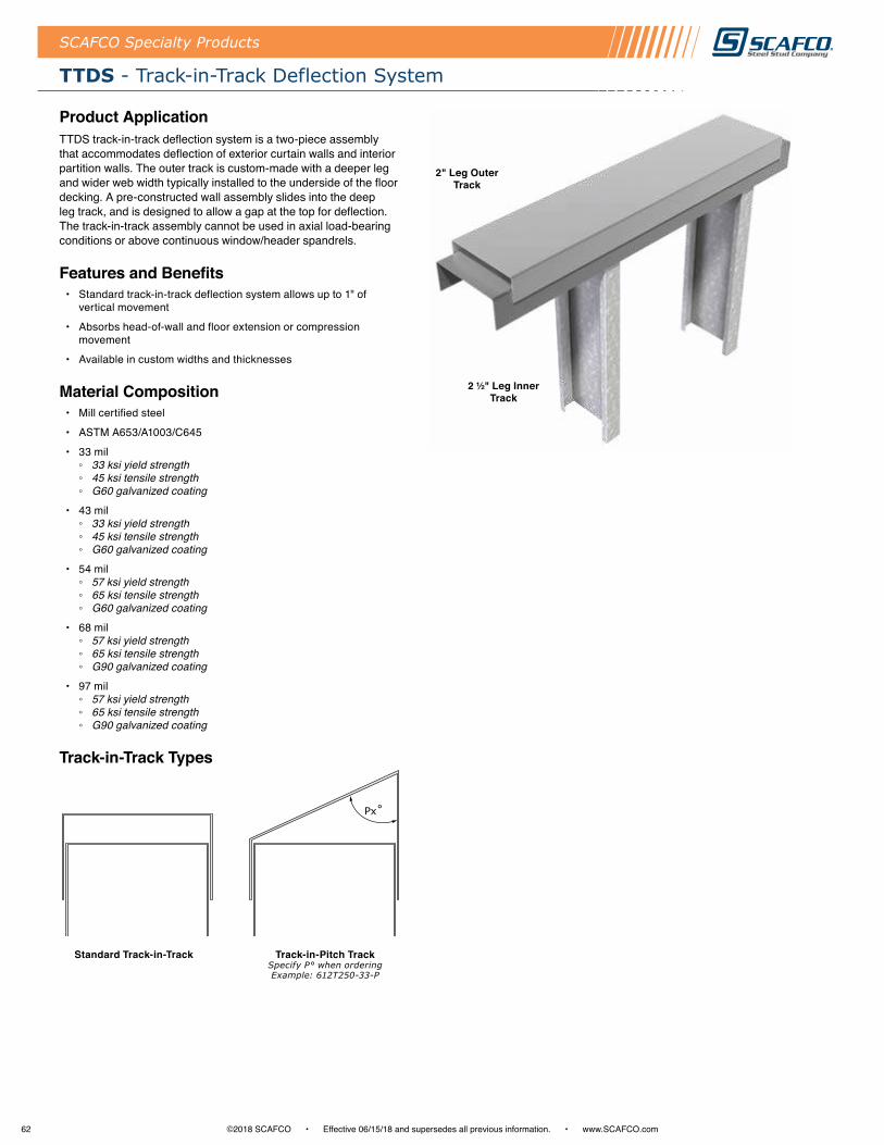
62 ©2018 SCAFCO • Effective 06/15/18 and supersedes all previous information . • www .SCAFCO .com
SCAFCO Specialty Products
TTDS - Track-in-Track Deflection System
Product ApplicationTTDS track-in-track deflection system is a two-piece assembly that accommodates deflection of exterior curtain walls and interior partition walls . The outer track is custom-made with a deeper leg and wider web width typically installed to the underside of the floor decking . A pre-constructed wall assembly slides into the deep leg track, and is designed to allow a gap at the top for deflection . The track-in-track assembly cannot be used in axial load-bearing conditions or above continuous window/header spandrels .
Features and Benefits • Standard track-in-track deflection system allows up to 1" of
vertical movement
• Absorbs head-of-wall and floor extension or compression movement
• Available in custom widths and thicknesses
Material Composition• Mill certified steel
• ASTM A653/A1003/C645
• 33 mil ◦ 33 ksi yield strength ◦ 45 ksi tensile strength ◦ G60 galvanized coating
• 43 mil ◦ 33 ksi yield strength ◦ 45 ksi tensile strength ◦ G60 galvanized coating
• 54 mil ◦ 57 ksi yield strength ◦ 65 ksi tensile strength ◦ G60 galvanized coating
• 68 mil ◦ 57 ksi yield strength ◦ 65 ksi tensile strength ◦ G90 galvanized coating
• 97 mil ◦ 57 ksi yield strength ◦ 65 ksi tensile strength ◦ G90 galvanized coating
Track-in-Track Types
Track-in-Pitch Track Specify P° when orderingExample: 612T250-33-P
Standard Track-in-Track
Px˚
2 ½" Leg Inner Track
2" Leg Outer Track
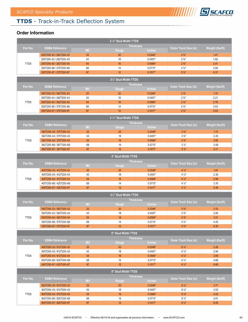
63©2018 SCAFCO • Effective 06/15/18 and supersedes all previous information . • www .SCAFCO .com
TTDS - Track-in-Track Deflection System
SCAFCO Specialty Products
Order Information2 ½" Stud Width TTDS
Part No. SSMA Reference Thickness Outer Track Size (in) Weight (lbs/ft)Mil Gauge Inches
TTDS
250T250-33 / 262T200-33 33 20 0.0346" 2 ⅝" 1.47250T250-43 / 262T200-43 43 18 0.0451" 2 ⅝" 1.92250T250-54 / 262T200-54 54 16 0.0566" 2 ⅝" 2.41250T250-68 / 275T200-68 68 14 0.0713" 2 ¾" 3.06250T250-97 / 275T200-97 97 12 0.1017" 2 ¾" 4.37
3 ⅝" Stud Width TTDS
Part No. SSMA Reference Thickness Outer Track Size (in) Weight (lbs/ft)Mil Gauge Inches
TTDS
362T250-33 / 375T200-33 33 20 0.0346" 3 ¾" 1.72362T250-43 / 375T200-43 43 18 0.0451" 3 ¾" 2.25362T250-54 / 375T200-54 54 16 0.0566" 3 ¾" 2.82362T250-68 / 387T200-68 68 14 0.0713" 3 ⅞" 3.58362T250-97 / 387T200-97 97 12 0.1017" 3 ⅞" 5.11
6" Stud Width TTDS
Part No. SSMA Reference Thickness Outer Track Size (in) Weight (lbs/ft)Mil Gauge Inches
TTDS
600T250-33 / 612T200-33 33 20 0.0346" 6 ⅛" 2.26600T250-43 / 612T200-43 43 18 0.0451" 6 ⅛" 2.94600T250-54 / 612T200-54 54 16 0.0566" 6 ⅛" 3.69600T250-68 / 625T200-68 68 14 0.0713" 6 ¼" 4.68600T250-97 / 625T200-97 97 12 0.1017" 6 ¼" 6.68
3½" Stud Width TTDS
Part No. SSMA Reference Thickness Outer Track Size (in) Weight (lbs/ft)Mil Gauge Inches
TTDS
350T250-33 / 362T200-33 33 20 0.0346" 2 ⅝" 1.70350T250-43 / 362T200-43 43 18 0.0451" 2 ⅝" 2.21350T250-54 / 362T200-54 54 16 0.0566" 2 ⅝" 2.78350T250-68 / 375T200-68 68 14 0.0713" 2 ¾" 3.53350T250-97 / 375T200-97 97 12 0.1017" 2 ¾" 5.03
5½" Stud Width TTDS
Part No. SSMA Reference Thickness Outer Track Size (in) Weight (lbs/ft)Mil Gauge Inches
TTDS
550T250-33 / 562T200-33 33 20 0.0346" 5 ⅝" 2.15550T250-43 / 562T200-43 43 18 0.0451" 5 ⅝" 2.80550T250-54 / 562T200-54 54 16 0.0566" 5 ⅝" 3.51550T250-68 / 575T200-68 68 14 0.0713" 5 ¾" 4.45550T250-97 / 575T200-97 97 12 0.1017" 5 ¾" 6.35
4" Stud Width TTDS
Part No. SSMA Reference Thickness Outer Track Size (in) Weight (lbs/ft)Mil Gauge Inches
TTDS
400T250-33 / 412T200-33 33 20 0.0346" 4 ⅛" 1.81400T250-43 / 412T200-43 43 18 0.0451" 4 ⅛" 2.36400T250-54 / 412T200-54 54 16 0.0566" 4 ⅛" 2.96400T250-68 / 425T200-68 68 14 0.0713" 4 ¼" 3.76400T250-97 / 425T200-97 97 12 0.1017" 4 ¼" 5.36
8" Stud Width TTDS
Part No. SSMA Reference Thickness Outer Track Size (in) Weight (lbs/ft)Mil Gauge Inches
TTDS
800T250-33 / 812T200-33 33 20 0.0346" 8 ⅛" 2.71800T250-43 / 812T200-43 43 18 0.0451" 8 ⅛" 3.53800T250-54 / 812T200-54 54 16 0.0566" 8 ⅛" 4.43800T250-68 / 825T200-68 68 14 0.0713" 8 ¼" 5.61800T250-97 / 825T200-97 97 12 0.1017" 8 ¼" 8.00
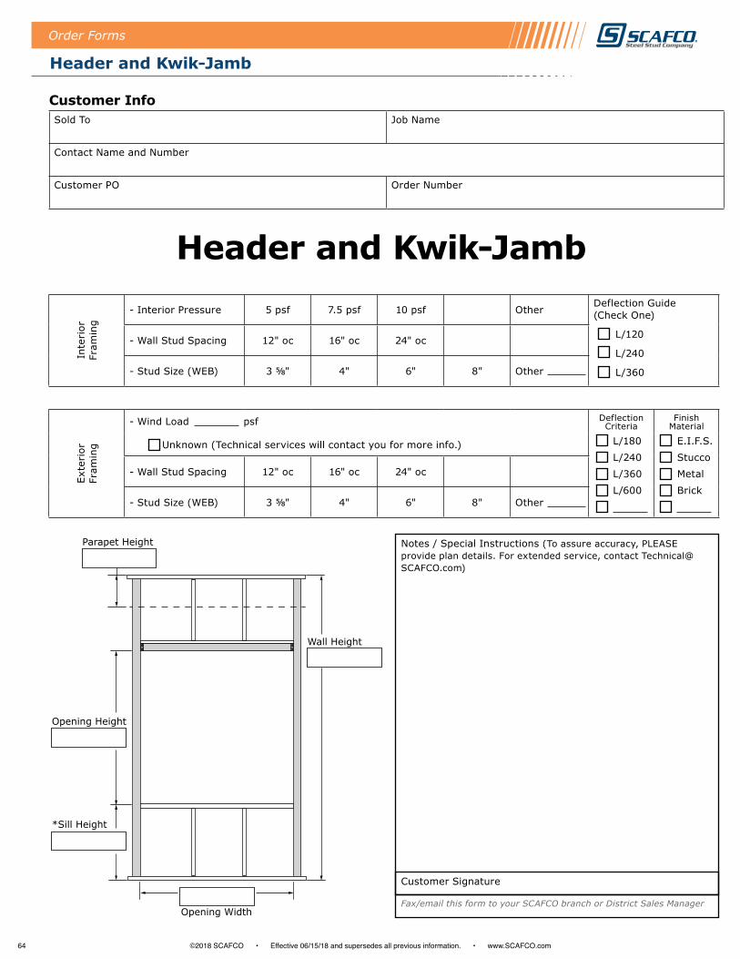
64 ©2018 SCAFCO • Effective 06/15/18 and supersedes all previous information . • www .SCAFCO .com
Order Forms
Header and Kwik-Jamb
Customer InfoSold To Job Name
Contact Name and Number
Customer PO Order Number
Header and Kwik-Jamb
Inte
rior
Fr
amin
g
- Interior Pressure 5 psf 7.5 psf 10 psf OtherDeflection Guide (Check One)
L/120
L/240
L/360
- Wall Stud Spacing 12" oc 16" oc 24" oc
- Stud Size (WEB) 3 ⅝" 4" 6" 8" Other
Exte
rior
Fr
amin
g
- Wind Load psf Deflection Criteria
Finish Material
Unknown (Technical services will contact you for more info.)
- Wall Stud Spacing 12" oc 16" oc 24" oc
- Stud Size (WEB) 3 ⅝" 4" 6" 8" Other
Parapet Height
Opening Width
*Sill Height
Opening Height
Wall Height
L/180
L/240
L/360
L/600
E.I.F.S.
Stucco
Metal
Brick
Notes / Special Instructions (To assure accuracy, PLEASE provide plan details. For extended service, contact [email protected])
Fax/email this form to your SCAFCO branch or District Sales Manager
Customer Signature
Order Forms

65©2018 SCAFCO • Effective 06/15/18 and supersedes all previous information . • www .SCAFCO .com
Perfect Curve™
Order Forms
Customer InfoSold To Job Name
Contact Name and Number
Customer PO Order Number
Item No.
Splice Tabs Welded No. of
PiecesThickness
(Mil)Length
(L)Web Depth
(W)Leg Height
(H)Inside Radius
(IR)Outside Radius
(OR)Part No.
(Office Use)
1.
2.
3.
4.
5.
6.
Notes / Special Instructions (To assure accuracy, PLEASE provide plan details. For extended service, contact [email protected])
Customer Signature Fax/email this form to your SCAFCO branch or District Sales Manager
W
H
L
IROR
Connection Rivets
Optional Splicing Tab
Standard Components *1½" Leg Height (H) *Steel Rivets 4" oc *10' Lengths (12' Max) *1⅝" Web Min. (W)
Curved Track

66 ©2018 SCAFCO • Effective 06/15/18 and supersedes all previous information . • www .SCAFCO .com
Order Forms
Perfect Curve™
Customer InfoSold To Job Name
Contact Name and Number
Customer PO Order Number
Item No.
Leg Splice Tabs Welded No. of
PiecesThickness
(Mil)Length
(L)Web Depth
(W)Leg Height
(H)Inside Radius
(IR)Outside Radius
(OR)Part No.
(Office Use) In Out1.
2.
3.
4.
5.
6.
Notes / Special Instructions (To assure accuracy, PLEASE provide plan details. For extended service, contact [email protected])
Customer Signature Fax/email this form to your SCAFCO branch or District Sales Manager
OptionalSplicing Tab
ConnectionRivets
IR OR
L
IR OR
Leg In Leg Out
H
W
H
W
Standard Components *1½" Leg Height (H) *Steel Rivets 4" oc *10' Lengths (12' Max)
L
Arched Track
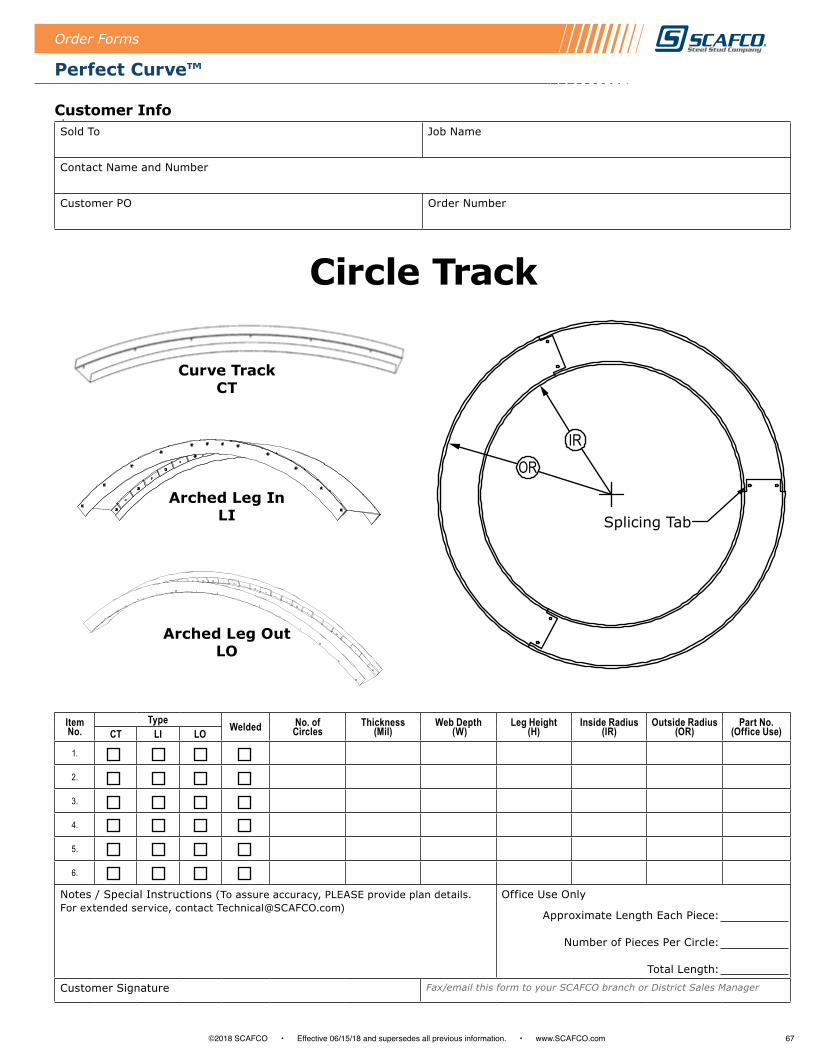
67©2018 SCAFCO • Effective 06/15/18 and supersedes all previous information . • www .SCAFCO .com
Perfect Curve™
Order Forms
Item No.
Type Welded No. of Circles
Thickness (Mil)
Web Depth (W)
Leg Height (H)
Inside Radius (IR)
Outside Radius (OR)
Part No. (Office Use)CT LI LO
1.
2.
3.
4.
5.
6.
Notes / Special Instructions (To assure accuracy, PLEASE provide plan details. For extended service, contact [email protected])
Office Use Only
Approximate Length Each Piece:
Number of Pieces Per Circle:
Total Length:
Customer Signature Fax/email this form to your SCAFCO branch or District Sales Manager
Splicing Tab
IROR
Curve TrackCT
Arched Leg InLI
Arched Leg OutLO
Customer InfoSold To Job Name
Contact Name and Number
Customer PO Order Number
Circle Track

68 ©2018 SCAFCO • Effective 06/15/18 and supersedes all previous information . • www .SCAFCO .com
Order Forms
Perfect Curve™
Item No.
Leg Welded No. of Pieces
Thickness (Mil)
Length (L)
Leg Height (H1)
Leg Height (H2)
Inside Radius (IR)
Outside Radius (OR)
Part No. (Office Use)In Out
1.
2.
3.
4.
5.
6.
Notes / Special Instructions (To assure accuracy, PLEASE provide plan details. For extended service, contact [email protected])
Customer Signature Fax/email this form to your SCAFCO branch or District Sales Manager
Leg Out
ConnectionRivets
IR OR
L
Leg InH2
H1
H2
H1
ORIR
L
Standard Components *1½" Leg Height (H) *Steel Rivets 4" oc *10' Lengths (12' Max)
Customer InfoSold To Job Name
Contact Name and Number
Customer PO Order Number
Curved Angle
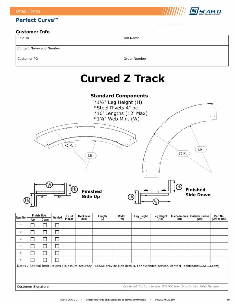
69©2018 SCAFCO • Effective 06/15/18 and supersedes all previous information . • www .SCAFCO .com
Perfect Curve™
Order Forms
Customer Info
Item No. Finish Side Welded No. of Pieces
Thickness (Mil)
Length (L)
Width (W)
Leg Height (H1)
Leg Height (H2)
Inside Radius (IR)
Outside Radius (OR)
Part No. (Office Use)Up Down
1.
2.
3.
4.
5.
6.
Notes / Special Instructions (To assure accuracy, PLEASE provide plan details. For extended service, contact [email protected])
Customer Signature Fax/email this form to your SCAFCO branch or District Sales Manager
IR
OR
LStandard Components *1½" Leg Height (H) *Steel Rivets 4" oc *10' Lengths (12' Max) *1⅝" Web Min. (W)
FinishedSide Up
WH2
H1
FinishedSide Down
W
H2
H1
Sold To Job Name
Contact Name and Number
Customer PO Order Number
Curved Z Track
O.R.I.R.
FINISH SIDE UPFINISH SIDE DOWN
O.R.
I.R.
IR
OR
LStandard Components *1½" Leg Height (H) *Steel Rivets 4" oc *10' Lengths (12' Max) *1⅝" Web Min. (W)
FinishedSide Up
WH2
H1
FinishedSide Down
W
H2
H1
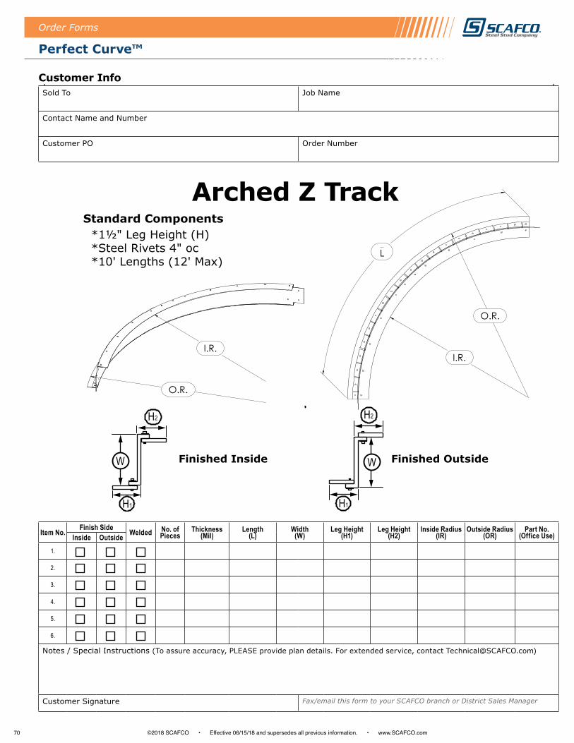
70 ©2018 SCAFCO • Effective 06/15/18 and supersedes all previous information . • www .SCAFCO .com
Perfect Curve™
Order Forms
Customer Info
Item No. Finish Side Welded No. of Pieces
Thickness (Mil)
Length (L)
Width (W)
Leg Height (H1)
Leg Height (H2)
Inside Radius (IR)
Outside Radius (OR)
Part No. (Office Use)Inside Outside
1.
2.
3.
4.
5.
6.
Notes / Special Instructions (To assure accuracy, PLEASE provide plan details. For extended service, contact [email protected])
Customer Signature Fax/email this form to your SCAFCO branch or District Sales Manager
IR
OR
L
Standard Components *1½" Leg Height (H) *Steel Rivets 4" oc *10' Lengths (12' Max)
Finished InsideW
H2
H1
Finished Outside
H2
H1
W
Sold To Job Name
Contact Name and Number
Customer PO Order Number
Arched Z TrackFINISH OUT
HEIGHT
LEG 1
LEG 2
FINISH IN
HEIGHT
LEG 1
LEG 2
FINISH IN OUT
HEIGHT
LEG 2
LEG 1
I.R.
L
O.R.
FINISH IN OUT
HEIGHT
LEG 1
LEG 2
I.R.
O.R.
IR
OR
L
Standard Components *1½" Leg Height (H) *Steel Rivets 4" oc *10' Lengths (12' Max)
Finished InsideW
H2
H1
Finished Outside
H2
H1
W

71©2018 SCAFCO • Effective 06/15/18 and supersedes all previous information . • www .SCAFCO .com
Table of Contents
Index - Alphabetical By Product
AC - Bypass Slab Secure Clip . . . . . . . . . . . . . . . . . . . . . . . 22-23
AS - Load-Bearing Secure Strut . . . . . . . . . . . . . . . . . . . . . . . . . 24
BC - Secure Bridge Clip . . . . . . . . . . . . . . . . . . . . . . . . . . . . . . . 32
Certification of Materials . . . . . . . . . . . . . . . . . . . . . . . . . . . . . . . . 7
Clip Comparison Table . . . . . . . . . . . . . . . . . . . . . . . . . . . . . . . . . 6
Custom Brake Shapes . . . . . . . . . . . . . . . . . . . . . . . . . . . . . . . . 45
DD - Deep Leg Seismic Drift Track . . . . . . . . . . . . . . . . . . . 60-61
DESC - Exterior Head-of-Wall Drift Clip . . . . . . . . . . . . . . . . . . 17
DPLC2 - Bypass Slab Drift Clip . . . . . . . . . . . . . . . . . . . . . . .14-15
D - Seismic Drift Track . . . . . . . . . . . . . . . . . . . . . . . . . . . . . 58-59
ELEV - Elevator Stud Clip . . . . . . . . . . . . . . . . . . . . . . . . . . 36-37
ESC - Exterior Head-of-Wall . . . . . . . . . . . . . . . . . . . . . . . . . . . 16
FA - Secure Floor Anchor Kit . . . . . . . . . . . . . . . . . . . . . . . . . . . 25
FTB - Fire Track Blocking (Shear Blocking) . . . . . . . . . . . . . . . 39
FTDC - Float Track Deflection Clip . . . . . . . . . . . . . . . . . . . 20-21
Header and Kwik-Jamb . . . . . . . . . . . . . . . . . . . . . . . . . . . . . . . 64
HG - Secure Header Gusset Plate . . . . . . . . . . . . . . . . . . . . . . . 33
Important Information and General Notes . . . . . . . . . . . . . . . . . . 4
KB - Kwik-Back Wall Support . . . . . . . . . . . . . . . . . . . . . . . . . . . 43
K - Kwik-Bridge Punch System . . . . . . . . . . . . . . . . . . . . . . . . . 35
MA - Multi-Use Secure Clip . . . . . . . . . . . . . . . . . . . . . . . . . 26-27
MB - Multi-Use Secure Clip . . . . . . . . . . . . . . . . . . . . . . . . . 28-29
MC - Multi-Use Secure Clip . . . . . . . . . . . . . . . . . . . . . . . . . 30-31
NS - Notched Stud Backing . . . . . . . . . . . . . . . . . . . . . . . . . 40-41
NT - Notched Track Backing . . . . . . . . . . . . . . . . . . . . . . . . . . . 42
Order Forms Perfect Curve™ . . . . . . . . . . . . . . . . . . . . . . . . .65-70
Perfect Curve™ Products . . . . . . . . . . . . . . . . . . . . . . . . . . . 52-53
PLC2 - Bypass Slab Slide Clip . . . . . . . . . . . . . . . . . . . . . . . . . . 11
PLC4 - Bypass Slab Slide Clip . . . . . . . . . . . . . . . . . . . . . . . . .8-10
PLS2 - Bypass Slab Slide Strut . . . . . . . . . . . . . . . . . . . . . . . . . 13
PLS3 - Bypass Slab Slide Strut . . . . . . . . . . . . . . . . . . . . . . . . . 12
Ponywall Support . . . . . . . . . . . . . . . . . . . . . . . . . . . . . . . . . . . . 44
Priceless HD Header . . . . . . . . . . . . . . . . . . . . . . . . . . . . . . . . . 48
Priceless HDR Header . . . . . . . . . . . . . . . . . . . . . . . . . . . . . . . . 49
Priceless Header and Kwik-Jamb System . . . . . . . . . . . . . . 46-47
Priceless Kwik-Jamb . . . . . . . . . . . . . . . . . . . . . . . . . . . . . . 50-51
SDLT - Slotted Deep Leg Track . . . . . . . . . . . . . . . . . . . . . . 56-57
SLT - Slotted Leg Track . . . . . . . . . . . . . . . . . . . . . . . . . . . . 54-55
SSWT - Splicing Slide Clip and Rigid Wall Tie . . . . . . . . . . . . . 18
STP - Bypass Slab Top Plate . . . . . . . . . . . . . . . . . . . . . . . . . . . 19
Table of Contents . . . . . . . . . . . . . . . . . . . . . . . . . . . . . . . . . . . .2-3
TB - Track Backing . . . . . . . . . . . . . . . . . . . . . . . . . . . . . . . . . . . 38
Thickness & Connection Capacities . . . . . . . . . . . . . . . . . . . . . . 5
TTDS - Track-in-Track Deflection System . . . . . . . . . . . . . . 62-63
WST - Web Stiffener Track . . . . . . . . . . . . . . . . . . . . . . . . . . . . . 34
Contact Engineering ServicesFor assistance with ordering or questions on your project, utilize SCAFCO Engineering Services:
Call: 509-789-8669 Email: Technical@SCAFCO .com Website: www .SCAFCO .com

www.SCAFCO.com
SCAFCO Spokane2800 E. Main AveSpokane, WA 99202509-343-9000
SCAFCO Stockton2525 S. Airport WayStockton, CA 95206209-670-8053
SCAFCO Steel FramingWith 60 years of manufacturing experience, SCAFCO has gained a worldwide reputation for high-quality products, great customer service, and strong corporate ethics. Our comprehensive team of engineers, administrative and office staff, and craftsmen focus on providing customer driven products. We currently have manufacturing facilities in Spokane, WA and Stockton, CA. We also feature press brakes and shears capable of making on demand, custom parts up to 24’ in length.
Engineering ServicesFor assistance with ordering or questions on your project, utilize SCAFCO Engineering Services:
Call: 509-789-8669Email: [email protected]
MANUFACTURING LOCATIONS
STEEL FRAMING CONNECTIONSCatalog 300