California Your Unk to ISO DOCKETdocketpublic.energy.ca.gov/PublicDocuments/Regulatory/Non...
43
California Independent @ California ISO Your Unk to Powor System Operator Corpa DOCKET June 15.2007 Michael King Panoche Energy Center, LLC kr I 7 mot 6229 White Alder Avon, IN 46123 Subject: lnterconnection Facilities Re-Study Report for Panoche Energy Center Project Dear Mr. King: Attached is the lnterconnection Facilities Re-Study (IFAR) Report for the interconnection of the proposed 401 MW Panoche Energy Center Project (Project)to the Pacific Gas & Electric Company's (PG&E) Panoche 230 kV Substation. The IFAR was performed by PG&E under the direction of the California ISO. The Project's proposed Commercial Operation Date is September 30, 2009. This IFAR confirms the results of the lnterconnection System Impact Re-study (a report issued on December 12,2006) and provides mitigation measures for the overloaded circuits along with their estimated cost. The IFAR also provides an option to employ Special Protection System (SPS) as a means to mitigate Category C overloads. The cost of lnterconnection Facilities (Direct Assignment Cost) to interconnect the project to Panoche Substation is approximately $2.72 million. The cost of Network Upgrades attributed to this project is approximately $8.18 million. Thus, the total cost responsibility for this project to reliably interconnect to the CAlSO Controlled Grid is $10.9 milllon. The project also exasperates loading on several other transmission circuits that are already found overloaded due to higher queued projects. The CAlSO has attributed the cost responsibility to those higher queued projects for such circuits. However, if any of those higher queued projects are withdrawn from the CAlSO queue, the cost responsibility will be re-allocated based on revised studies. It is very likely that Panoche Energy Center project may have to pick up additional cost in such a scenario. The CAlSO also performed a Deliverability Assessment for this project pursuant to LGlP section 3.3.3 and found that the project is 100% deliverable without assigning any additional upgrades to the proiect. Therefore. based on this study. 100% of the output of the project would be eligible to sell ~ e s o u r c e - ~ d e q u a c ~ The study resulk and ~a~acrt);. assumptions for this Deliverability Assessment are posted on our website at This project is now approved to interconnect to the CAlSO Controlled Grid after making the required system upgrades and be eligible to deliver the project's output using available transmission. The IFAR results meeting will be coordinated and scheduled by the CAlSO Project Manager Ed Fishback (916) 608-5836 (-)w i th i n 10 business days following receipt of the lnterconnection Facilities Re-Study Report. CAlSO 151 Blue Ravine Road Folsom, Caliiornia 95630 Page 1 (916) 351400
Transcript of California Your Unk to ISO DOCKETdocketpublic.energy.ca.gov/PublicDocuments/Regulatory/Non...

California Independent @ California ISOYour Unk to Powor System Operator Corpa
DOCKET June 15.2007
Michael King Panoche Energy Center, LLC k r I 7 mot6229 White Alder Avon, IN 46123
Subject: lnterconnection Facilities Re-Study Report for Panoche Energy Center Project
Dear Mr. King:
Attached is the lnterconnection Facilities Re-Study (IFAR) Report for the interconnection of the proposed 401 MW Panoche Energy Center Project (Project) to the Pacific Gas & Electric Company's (PG&E) Panoche 230 kV Substation. The IFAR was performed by PG&E under the direction of the California ISO. The Project's proposed Commercial Operation Date is September 30, 2009.
This IFAR confirms the results of the lnterconnection System Impact Re-study (a report issued on December 12,2006) and provides mitigation measures for the overloaded circuits along with their estimated cost. The IFAR also provides an option to employ Special Protection System (SPS) as a means to mitigate Category C overloads.
The cost of lnterconnection Facilities (Direct Assignment Cost) to interconnect the project to Panoche Substation is approximately $2.72 million. The cost of Network Upgrades attributed to this project is approximately $8.18 million. Thus, the total cost responsibility for this project to reliably interconnect to the CAlSO Controlled Grid is $10.9 milllon.
The project also exasperates loading on several other transmission circuits that are already found overloaded due to higher queued projects. The CAlSO has attributed the cost responsibility to those higher queued projects for such circuits. However, if any of those higher queued projects are withdrawn from the CAlSO queue, the cost responsibility will be re-allocated based on revised studies. It is very likely that Panoche Energy Center project may have to pick up additional cost in such a scenario.
The CAlSO also performed a Deliverability Assessment for this project pursuant to LGlP section 3.3.3 and found that the project is 100% deliverable without assigning any additional upgrades to the proiect. Therefore. based on this study. 100% of the output of the project would be eligible to sell ~esource-~dequac~ The study resulk and ~a~acr t ) ; . assumptions for this Deliverability Assessment are posted on our website at
This project is now approved to interconnect to the CAlSO Controlled Grid after making the required system upgrades and be eligible to deliver the project's output using available transmission.
The IFAR results meeting will be coordinated and scheduled by the CAlSO Project Manager Ed Fishback (916) 608-5836 (-)within 10 business days following receipt of the lnterconnection Facilities Re-Study Report.
CAlSO 151 Blue Ravine Road
Folsom, Caliiornia 95630 Page 1 (916) 351400

CAISO 151 Blue Ravine Road
Folsom, California 95630 Page 2 (916) 351-4400
Should you have questions regarding the Study, please contact Nisar Shah at (916) 608-7376 ([email protected]) or myself at (916) 608-5880 ([email protected]). Sincerely, Gary DeShazo Director of Regional Transmission - North DP/GD:dd Attachment cc: Gary Chandler President, Panoche Energy Center, LLC P O Box 95592 South Jordan, UT 84095-0592 [email protected] via e-mail: Art McAuley (PG&E) ([email protected]) Madeline Aldridge, (PG&E) ([email protected]) Mark Esguerra (PG&E) ([email protected]) Chris Gillis (PG&E) ([email protected]) Albert Wong (PG&E) ([email protected]) CAISO via email: Ed Fishback ([email protected]) Dennis Peters ([email protected]) Nisar Shah ([email protected]) ISO Regional Transmission North & South

InterconnectionFacilities Re-studyReportGeneration Interconnection
Panoche Energy Center, LLC
Panoche Energy CenterProject
June14,2007

TableofContents
1. Executive Summary...................................................................................................................1
2. Project Information and Interconnection Plan ..........................................................................3
3. Cost Summary and Schedule ...................................................................................................4
3.1 Direct Assignment Cost..............................................................................................................4
3.2 Network Upgrades Costs...........................................................................................................5
3.3 Tentative Construction Schedule...............................................................................................6
4. Study Assumptions ....................................................................................................................7
5. Interconnection System Impact Re-study Results...................................................................7
6. Transmission Line Evaluation ...................................................................................................9
6.1 Direct Assignment Work Scope.................................................................................................9
6.2 Network Upgrade Work Scope..................................................................................................9
7. Substation Evaluation ................................................................................................................9
7.1 Direct Assignment Work Scope.................................................................................................9
7.2 Network Upgrade Work Scope............................................................................................... 10
8. Land Services Evaluation....................................................................................................... 10
8.1 Direct Assignment Work Scope.............................................................................................. 10
8.2 Network Upgrade Work Scope............................................................................................... 10
9. Environmental Evaluation/ Permitting.................................................................................... 11
9.1 CPUC General Order 131-D................................................................................................... 11
9.2 CPUC Section 851.................................................................................................................. 12
10. Study Updates......................................................................................................................... 12
11. Stand-by Power....................................................................................................................... 12
Appendices
A. Study PlanB. Substation Work ScopeC. Protection RequirementsD. Telecommunication Requirements

PANOCHE ENERGY CENTER, LLCPANOCHE ENERGY CENTER INTERCONNECTION FACILITIES RE-STUDY REPORT
JUNE 14, 2007
1
1. Executive Summary
Panoche Energy Center, LLC, an Interconnection Customer (IC), has submittedan Interconnection Facilities Re-study (IFAR) request to the CaliforniaIndependent System Operator Corporation (CAISO) for their Panoche EnergyCenter Project (Project). The maximum net output to the CAISO Controlled Gridis 401 MW. The expected in-service date is September 2009. The IC proposesto interconnect the Project onto Pacific Gas and Electric Company’s (PG&E) 230kV bus at Panoche Substation.
Under the direction of the CAISO, PG&E had performed an InterconnectionSystem Impact Re-study (ISIR) for this Project and issued an ISIR report onDecember 12, 2006. The ISIR revealed different system impacts to the CAISOControlled Grid as compared to what was determined in the originalInterconnection System Impact Study. The already issued Facilities Study (FS)report, dated February 13, 2006, was not reflecting the updated system impacts.Therefore, according to the FERC mandated Large Generator InterconnectionProcedures (LGIP), the CAISO directed PG&E to conduct a re-study, anInterconnection Facilities Re-study (IFAR), for the Project. This IFAR provides:
1. Work scope and cost estimates for the Direct Assignment facilities1 necessaryto interconnect the Project to the CAISO Controlled Grid at the Point ofInterconnection (POI), and
2. Work scope and cost estimates for the Network Upgrade facilities2 necessaryto interconnect the Project to the CAISO Controlled Grid beyond the POI andto mitigate the impact of the Project under various system conditions.
The Direct Assignment facilities work scope consists of the following items:
Provide transmission interconnection from the Project to the POI
Install a new 230 kV breaker at Panoche Substation to interconnect theProject
Install a fully redundant, double-pilot current differential scheme
Provide pre-parallel inspection, testing, SCADA, EMS setup, engineeringsupport, etc.
The Network Upgrade facilities work scope consists of the following items:
Reconfigure the existing 230 kV bus to accommodate the Project
Re-conductor the Wilson-Gregg 230 kV Line Section between Storey 1and Gregg (about 1 mile)
1 The transmission facilities necessary to physically and electrically interconnect the Project to the Point ofInterconnection of the CAISO Controlled Grid
2 The transmission facilities necessary to interconnect the Project safely and reliably to the CAISO Controlled Grid,beyond the Point of Interconnection

PANOCHE ENERGY CENTER, LLCPANOCHE ENERGY CENTER INTERCONNECTION FACILITIES RE-STUDY REPORT
JUNE 14, 2007
2
Install associated relays/equipment at Panoche Substations for protectionand communication, and
Install special protection schemes (SPS) required to mitigate facilityoverloads under Category ”C” contingencies.
The cost of the Direct Assignment facilities to interconnect the Project isapproximately $2.72 million which includes ITCC3.
The cost of the Network upgrade facilities to interconnect the Project isapproximately $8.18 million (excluding the land cost).
The total interconnection cost of the Project is approximately $10.9 million.
Currently PG&E has a reliability project, the Modular Protection AutomationControl (MPAC) Project, for the 230 kV bus at Panoche Substation. Thisproject is under the management’s review, and the scheduled completiondate is December 2008. The work scope of the MPAC Project includessome of the work scope as identified in the IFAR. Should the MPAC Projectbe implemented, these identified generation interconnection work scopewill not be required by the generation interconnection. However, if theMPAC Project does not materialize, the generation interconnection will beresponsible for these work scope items.
Note that the above cost estimates are including the work scope items thatalso covered by the MPAC Project.
3 Income Tax Component of Contribution (currently at 36%)

PANOCHE ENERGY CENTER, LLCPANOCHE ENERGY CENTER INTERCONNECTION FACILITIES RE-STUDY REPORT
JUNE 14, 2007
3
2. Project Information and Interconnection Plan
The Project consists of four gas turbine generators rated for 410 MW with a plantauxiliary load of 9 MW. The maximum net output to the grid will be 401 MW.Each generator will have one 13.8/230 kV, 125 MVA step-up transformer. TheProject will connect to the 230 kV bus at PG&E’s Panoche Substation via agenerator tie line to be built by the IC.
A conceptual one-line diagram of the Project is shown in Figure 2-1. Figure 2-2shows the approximate location of the Project and transmission facilities in thearea.
Figure 2-1: Conceptual Project One Line Diagram
102.5 MW
Panoche-Kearney230 kV
Los Banos-Panoche #2230kV
Coburn-Panoche230 kV
Los Banos-Panoche #1230 kV
Dos AmigosPP-Panoche230kV
PANOCHE SUBSTATION
230 kV Bus
230 kV Bus
102.5 MW 102.5 MW
PANOCHE ENERGYCENTER PROJECT
x
Point ofInterconnection
Generator Tie Line
102.5 MW
Gates-Panoche#1 230 kV
Gates-Panoche#2 230 kV
Panoche-Helm230 kV
Moss Landing-Panoche #2230kV
115 kV Bus
125MVA
New Bus Extension (2 bays)Relocate the Gates-Panoche#1 & 2 230 kV lines
125MVA
125MVA
125MVA
322312
NEW
202 282
242 232
272
252 262 332 212 222
Load
Install a new busParallel breakerin a spare bay
Add two new sectionalizingbreakers (utilize the bayvacated by the Gates-Panoche #1 230 kV line)
NEW
NEW
NEW
Add a new breaker for the interconnection (utilizethe bay vacated by the Gates-Panoche #2 230 kV line)
102.5 MW
Panoche-Kearney230 kV
Los Banos-Panoche #2230kV
Coburn-Panoche230 kV
Los Banos-Panoche #1230 kV
Dos AmigosPP-Panoche230kV
PANOCHE SUBSTATION
230 kV Bus
230 kV Bus
102.5 MW 102.5 MW
PANOCHE ENERGYCENTER PROJECT
x
Point ofInterconnection
Generator Tie Line
102.5 MW
Gates-Panoche#1 230 kV
Gates-Panoche#2 230 kV
Panoche-Helm230 kV
Moss Landing-Panoche #2230kV
115 kV Bus
125MVA
New Bus Extension (2 bays)Relocate the Gates-Panoche#1 & 2 230 kV lines
125MVA
125MVA
125MVA
322312
NEW
202 282
242 232
272
252 262 332 212 222
Load
Install a new busParallel breakerin a spare bay
Add two new sectionalizingbreakers (utilize the bayvacated by the Gates-Panoche #1 230 kV line)
NEW
NEW
NEW
Add a new breaker for the interconnection (utilizethe bay vacated by the Gates-Panoche #2 230 kV line)

PANOCHE ENERGY CENTER, LLCPANOCHE ENERGY CENTER INTERCONNECTION FACILITIES RE-STUDY REPORT
JUNE 14, 2007
4
Figure 2-2: Location Map
3. Cost Summary and Schedule
A cost summary is provided in Table 3-1, with more detailed Direct Assignmentand Network Upgrade facilities costs provided in Subsection 3.1 and Subsection3.2. Costs provided are not final and will need to be reconciled with actual costsupon completion of the Project.
Table 3-1 Cost Estimate SummaryTotal Direct Assignment Cost $2,000,000ITCC Tax @ 36 % $720,000Total Direct Assignment Facilities Cost with ITCC $ 2,720,000
Total Network Upgrade Cost $8,180,000Total Network Upgrade Facilities Cost $ 8,180,000
Total Project Interconnection Cost $ 10,900,000
3.1 Direct AssignmentCost
Cost estimates for the Direct Assignment facilities required to interconnect theProject is summarized in Table 3-2. These facilities are necessary tophysically and electrically interconnect the Project to the POI on the CAISOControlled Grid.
P A N O C H EW / O P A N O C H E R O A D . 2 M I E / O H W Y 5
M E N D O T A9 3 6 4 0
O w n e r : P G EG I S _ I D : 7 1 5 2 1
S A P F u n c t L o c # : E T S . 1 1 . 1 0 1 3 6
P A N O C H EW / O P A N O C H E R O A D . 2 M I E / O H W Y 5
M E N D O T A9 3 6 4 0
O w n e r : P G EG I S _ I D : 7 1 5 2 1
S A P F u n c t L o c # : E T S . 1 1 . 1 0 1 3 6
P A N O C H EW / O P A N O C H E R O A D . 2 M I E / O H W Y 5
M E N D O T A9 3 6 4 0
O w n e r : P G EG I S _ I D : 7 1 5 2 1
S A P F u n c t L o c # : E T S . 1 1 . 1 0 1 3 6
P A N O C H EW / O P A N O C H E R O A D . 2 M I E / O H W Y 5
M E N D O T A9 3 6 4 0
O w n e r : P G EG I S _ I D : 7 1 5 2 1
S A P F u n c t L o c # : E T S . 1 1 . 1 0 1 3 6
P A N O C H EW / O P A N O C H E R O A D . 2 M I E / O H W Y 5
M E N D O T A9 3 6 4 0
O w n e r : P G EG I S _ I D : 7 1 5 2 1
S A P F u n c t L o c # : E T S . 1 1 . 1 0 1 3 6
W E L L H E A D P O W E R P A N O C H E4 3 6 4 9 W P A N O C H E R O A DM E N D O T A9 3 6 4 0O w n e r : n o n P G EG I S _ I D : 7 2 4 6 1S A P F u n c t L o c # :
W E L L H E A D P O W E R P A N O C H E4 3 6 4 9 W P A N O C H E R O A DM E N D O T A9 3 6 4 0O w n e r : n o n P G EG I S _ I D : 7 2 4 6 1S A P F u n c t L o c # :
W E L L H E A D P O W E R P A N O C H E4 3 6 4 9 W P A N O C H E R O A DM E N D O T A9 3 6 4 0O w n e r : n o n P G EG I S _ I D : 7 2 4 6 1S A P F u n c t L o c # :
W E L L H E A D P O W E R P A N O C H E4 3 6 4 9 W P A N O C H E R O A DM E N D O T A9 3 6 4 0O w n e r : n o n P G EG I S _ I D : 7 2 4 6 1S A P F u n c t L o c # :
W E L L H E A D P O W E R P A N O C H E4 3 6 4 9 W P A N O C H E R O A DM E N D O T A9 3 6 4 0O w n e r : n o n P G EG I S _ I D : 7 2 4 6 1S A P F u n c t L o c # :
L OS
BAN
OS
-PA
NOCH
E#1 +
- 20074-
23 0kV
GAT
ES-PA
NO
CHE
#2- 2004 2-
230kV
P ANOC
H E-H
ELM+
-2 0109 -2 30
k V
CH
ENEY
# 1T AP
- 1025 5A -115
kV
P AN O C H E -ME N D O T A
- 10 25 5 -1 1 5 k V
PAN
OCHE
-OR
OL O
MA
- 10 256-1 15
kV
WP A N O C H E
R D
WP A N O C H E
R D
WP A N O C H E R D
WP A N O C H E
R D
WP A N O C H E
R D
PANOCHE ENERGYCENTER PROJECT
GENERATORTIE LINE
230 kV BUS
New bus extension & Relocate theGates-Panoche #1 & #2 230 kV lines
PANOCHESUBSTATION
P A N O C H EW / O P A N O C H E R O A D . 2 M I E / O H W Y 5
M E N D O T A9 3 6 4 0
O w n e r : P G EG I S _ I D : 7 1 5 2 1
S A P F u n c t L o c # : E T S . 1 1 . 1 0 1 3 6
P A N O C H EW / O P A N O C H E R O A D . 2 M I E / O H W Y 5
M E N D O T A9 3 6 4 0
O w n e r : P G EG I S _ I D : 7 1 5 2 1
S A P F u n c t L o c # : E T S . 1 1 . 1 0 1 3 6
P A N O C H EW / O P A N O C H E R O A D . 2 M I E / O H W Y 5
M E N D O T A9 3 6 4 0
O w n e r : P G EG I S _ I D : 7 1 5 2 1
S A P F u n c t L o c # : E T S . 1 1 . 1 0 1 3 6
P A N O C H EW / O P A N O C H E R O A D . 2 M I E / O H W Y 5
M E N D O T A9 3 6 4 0
O w n e r : P G EG I S _ I D : 7 1 5 2 1
S A P F u n c t L o c # : E T S . 1 1 . 1 0 1 3 6
P A N O C H EW / O P A N O C H E R O A D . 2 M I E / O H W Y 5
M E N D O T A9 3 6 4 0
O w n e r : P G EG I S _ I D : 7 1 5 2 1
S A P F u n c t L o c # : E T S . 1 1 . 1 0 1 3 6
W E L L H E A D P O W E R P A N O C H E4 3 6 4 9 W P A N O C H E R O A DM E N D O T A9 3 6 4 0O w n e r : n o n P G EG I S _ I D : 7 2 4 6 1S A P F u n c t L o c # :
W E L L H E A D P O W E R P A N O C H E4 3 6 4 9 W P A N O C H E R O A DM E N D O T A9 3 6 4 0O w n e r : n o n P G EG I S _ I D : 7 2 4 6 1S A P F u n c t L o c # :
W E L L H E A D P O W E R P A N O C H E4 3 6 4 9 W P A N O C H E R O A DM E N D O T A9 3 6 4 0O w n e r : n o n P G EG I S _ I D : 7 2 4 6 1S A P F u n c t L o c # :
W E L L H E A D P O W E R P A N O C H E4 3 6 4 9 W P A N O C H E R O A DM E N D O T A9 3 6 4 0O w n e r : n o n P G EG I S _ I D : 7 2 4 6 1S A P F u n c t L o c # :
W E L L H E A D P O W E R P A N O C H E4 3 6 4 9 W P A N O C H E R O A DM E N D O T A9 3 6 4 0O w n e r : n o n P G EG I S _ I D : 7 2 4 6 1S A P F u n c t L o c # :
L OS
BAN
OS
-PA
NOCH
E#1 +
- 20074-
23 0kV
GAT
ES-PA
NO
CHE
#2- 2004 2-
230kV
P ANOC
H E-H
ELM+
-2 0109 -2 30
k V
CH
ENEY
# 1T AP
- 1025 5A -115
kV
P AN O C H E -ME N D O T A
- 10 25 5 -1 1 5 k V
PAN
OCHE
-OR
OL O
MA
- 10 256-1 15
kV
WP A N O C H E
R D
WP A N O C H E
R D
WP A N O C H E R D
WP A N O C H E
R D
WP A N O C H E
R D
PANOCHE ENERGYCENTER PROJECT
GENERATORTIE LINE
230 kV BUS
New bus extension & Relocate theGates-Panoche #1 & #2 230 kV lines
PANOCHESUBSTATION

PANOCHE ENERGY CENTER, LLCPANOCHE ENERGY CENTER INTERCONNECTION FACILITIES RE-STUDY REPORT
JUNE 14, 2007
5
Table 3-2 Direct Assignment Cost EstimatesSubstation Work
Panoche SubstationInstall a new 230 kV breaker & associated
equipment $1,300,000
Perform pre-parallel inspection, testing,SCADA, EMS setup, Maintenance, etc. $300,000
The Project SitePerform pre-parallel inspection, testing,SCADA, EMS setup, Maintenance, etc. $200,000
Subtotal Substation Work $1,800,000
Transmission Line WorkProvide interconnection between generator tieline and the Switching Station $150,000
Subtotal Transmission Line Work $150,000
Land Services WorkLand engineering support, rights–of-way,property improvement, and permitting activitiesto support construction of the generator tie line
$50,000
Subtotal Land Services Work $50,000
Total Direct Assignment Cost before ITCC $2,000,000
3.2 Network Upgrades Costs
Cost Estimates for the Network Upgrade facilities required to interconnect theProject is summarized in Table 3-3. These facilities are necessary tophysically and electrically interconnect the Project on the CAISO ControlledGrid beyond the POI.

PANOCHE ENERGY CENTER, LLCPANOCHE ENERGY CENTER INTERCONNECTION FACILITIES RE-STUDY REPORT
JUNE 14, 2007
6
Table 3-3 Network Upgrade Cost EstimatesSubstation Work
Panoche SubstationInstall two 230 kV bus sectionalizing breakersand associated equipment* $1,600,000*
Extend the 230 kV bus for two bays and re-locate breakers for the Gates-Panoche #1and #2 230 kV lines*
$3,600,000*
Install a bus parallel breaker* $700,000*Gregg SubstationInstall two SPS $500,000
Sanger SubstationInstall one SPS $250,000
Subtotal Substation Work $6,650,000
Transmission Line WorkRelocate the Gates-Panoche #1 and #2 230kV lines* $970,000*
Re-conductor the Wilson-Gregg 230 kV Line(section between Storey 1 and Gregg Sub) $360,000
Subtotal Transmission LineWork
$1,330,000
Land Services WorkLand engineering support, rights–of-way andpermitting activities to support reconductoring $ 50,000
Land engineering support, rights–of-way, landacquisition property improvement, andpermitting activities to support bus extensionand transmission line work *
$150,000*
Subtotal Land Service Work $200,000
Total Network Upgrade Cost $8,180,000* These Work Scope and cost estimates are also in PG&E’s MPAC Project.
3.3 Tentative Construction Schedule
The tentative schedule to construct the Direct Assignment and NetworkUpgrade facilities based on the work scope outlined in this IFAS isapproximately between 24 and 36 months from the execution of the LargeGenerator Interconnection Agreement (LGIA) and payment of the estimatedDirect Assignment and Network Upgrade facilities costs. This schedulereflects only the time PG&E requires to engineer, design, schedule, procurematerials and construct the necessary facilities.
The construction schedule includes only the time required to obtain permitsanticipated in Section 8. Other permits that may be required by the CPUC,state, local, or federal agencies are described in Section 9. Additional permitsrequired beyond those anticipated will impact the Project’s schedule.

PANOCHE ENERGY CENTER, LLCPANOCHE ENERGY CENTER INTERCONNECTION FACILITIES RE-STUDY REPORT
JUNE 14, 2007
7
PG&E cannot guarantee that such interconnection can be completed bySeptember 2009, due to the potential work required for thisinterconnection. However, PG&E will work with the IC to achieve thatinterconnection as quickly as possible.
4. Study Assumptions
PG&E conducted the IFAR using the following assumptions:
1. The Project consists of four gas turbine generators, each rated for 102.5 MW.The maximum output is 410 MW with an expected plant load of 9 MW.Therefore, the maximum net output to the CAISO Controlled Grid is 401 MW.
2. The expected commercial operation date is September 2009.
3. The Project employs four step-up transformers, one for each generator. Eachtransformer is a three phase, 13.8/230 kV, rated at 75/100/125 MVA(OA/FA/FA), and with an impedance of 10% at 75 MVA base.
4. The IC will engineer, procure, construct, and maintain its project facility.
5. The IC will engineer, procure, and construct the generator tie line (from theProject’s switchyard to Panoche Substation). The generator tie line is about1,000 feet long with 795 ACSS conductor or equivalent conductors.
6. This study will take into account the planned generating facilities andtransmission projects, in PG&E’s service territory, whose schedule isconcurrent with or precede the Project’s schedule.
Currently PG&E has a reliability project, the Modular Protection AutomationControl (MPAC) Project, for the 230 kV bus at Panoche Substation. Thisproject is under the management’s review, and the scheduled completiondate is December 2008. The work scope of the MPAC Project includessome of the work scope as identified in the IFAR. Should the MPAC Projectbe implemented, these identified generation interconnection work scopewill not be required by the generation interconnection. However, if theMPAC Project does not materialize, the generation interconnection will beresponsible for these work scope items.
5. Interconnection System Impact Re-study Results
The ISIR issued on December 12, 2006 concluded that the Project would:
1) Exacerbate one normal pre-project overload:
The Borden-Gregg 230 kV Line - This line overloaded as a result of ageneration Project P0507 with a higher queue position and an earlieronline date. Project P0507 has been assigned the responsibility for

PANOCHE ENERGY CENTER, LLCPANOCHE ENERGY CENTER INTERCONNECTION FACILITIES RE-STUDY REPORT
JUNE 14, 2007
8
mitigating this overload. However, should this project not materialize, theIC may be responsible for mitigating this overload.
2) Cause one new Category B emergency overload:
TheWilson-Gregg 230 kV Line (section between Storey 1 and Greggsubstations) - The Project will provide mitigation.
3) Exacerbate five pre-project Category B emergency overloads. Projectscausing these pre-project overloads were assigned the responsibility formitigating these overloads. However, should these projects not materialize,the IC may be responsible for mitigating these overloads.
4) Cause three new Category C overloads:
The Coppermine-Tivy Valley 70 kV Line
The Herndon-Ashlan 230 kV Line (section between Figarden Tap 1 andAshlan)
The Wilson-Oro Loma 115 kV Line (section between LeGrand Jct andWilson)
The Project will install Special Protection Schemes (SPS) to mitigate theseoverloads.
5) Exacerbate eleven pre-project Category C emergency overloads. Projectscausing these pre-project overloads were assigned the responsibility formitigating these overloads. However, should these projects not materialize,the IC may be responsible for mitigating these overloads.
6) Overstress one 115 kV breaker (CB 112) and two 230 kV breakers (CB 222and 322) at Panoche Substation. A project with a higher queue position andan earlier online date is currently responsible for replacing these threebreakers. However, should this project not materialize, the IC may beresponsible for replacing these breakers.
7) Cause minimal adverse transient performance impacts on the transmissionsystem.
8) Require the Project to install a fully redundant, double-pilot current differentialscheme for the 230 kV generator tie line as well as replacement of fourcurrent transformers (CTs) and their associated protective relays on four 230kV breakers at Panoche Substation.
PANOCHE ENERGY CENTER, LLCPANOCHE ENERGY CENTER INTERCONNECTION FACILITIES RE-STUDY REPORT
JUNE 14, 2007
9
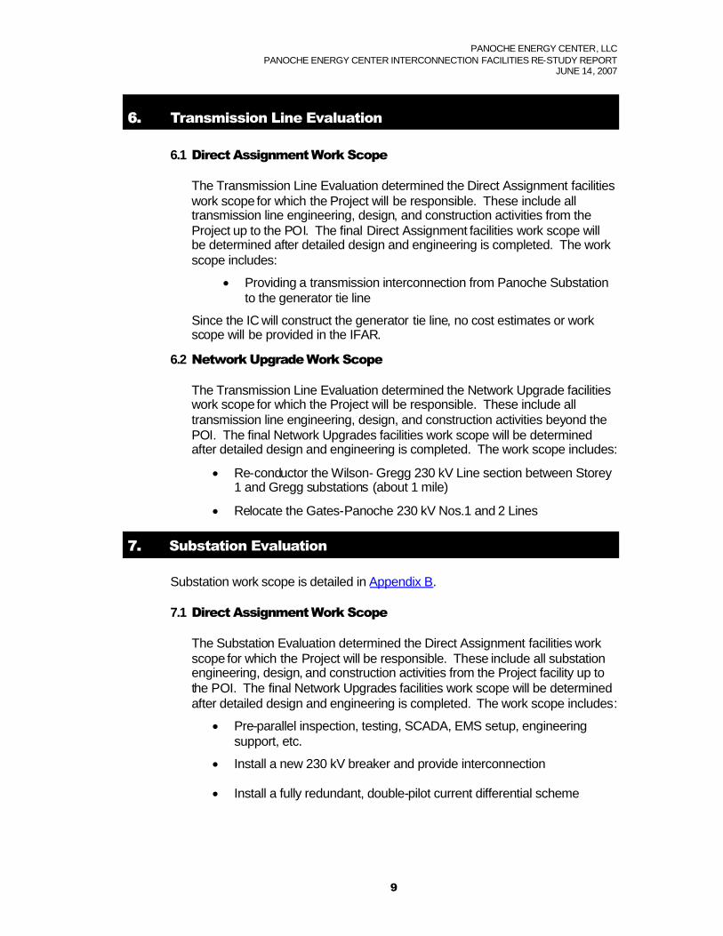
6. Transmission Line Evaluation
6.1 Direct AssignmentWork Scope
The Transmission Line Evaluation determined the Direct Assignment facilitieswork scope for which the Project will be responsible. These include alltransmission line engineering, design, and construction activities from theProject up to the POI. The final Direct Assignment facilities work scope willbe determined after detailed design and engineering is completed. The workscope includes:
Providing a transmission interconnection from Panoche Substationto the generator tie line
Since the IC will construct the generator tie line, no cost estimates or workscope will be provided in the IFAR.
6.2 Network UpgradeWork Scope
The Transmission Line Evaluation determined the Network Upgrade facilitieswork scope for which the Project will be responsible. These include alltransmission line engineering, design, and construction activities beyond thePOI. The final Network Upgrades facilities work scope will be determinedafter detailed design and engineering is completed. The work scope includes:
Re-conductor the Wilson- Gregg 230 kV Line section between Storey1 and Gregg substations (about 1 mile)
Relocate the Gates-Panoche 230 kV Nos.1 and 2 Lines
7. Substation Evaluation
Substation work scope is detailed in Appendix B.
7.1 Direct AssignmentWork Scope
The Substation Evaluation determined the Direct Assignment facilities workscope for which the Project will be responsible. These include all substationengineering, design, and construction activities from the Project facility up tothe POI. The final Network Upgrades facilities work scope will be determinedafter detailed design and engineering is completed. The work scope includes:
Pre-parallel inspection, testing, SCADA, EMS setup, engineeringsupport, etc.
Install a new 230 kV breaker and provide interconnection
Install a fully redundant, double-pilot current differential scheme

PANOCHE ENERGY CENTER, LLCPANOCHE ENERGY CENTER INTERCONNECTION FACILITIES RE-STUDY REPORT
JUNE 14, 2007
10
7.2 Network UpgradeWork Scope
The Substation Evaluation determined the Network Upgrade facilities workscope for which the Project will be responsible. These include all substationengineering, design, and construction activities beyond the POI. The finalNetwork Upgrades facilities work scope will be determined after detaileddesign and engineering is completed. The work scope includes:
Extend the 230 kV bus for two new bays
Re-locate two 230 kV breakers (for relocation of the Gates-PanocheNos. 1 and 2 230 kV lines)
Install two sectionalizing breakers
Install associated protection relays/equipment
Installation of SPS to mitigate the following three Category Cemergency overloads:
1. The Coppermine-Tivy Valley 70 kV Line (location: SangerSubstation)
2. The Herndon-Ashlan 230 kV Line section between Figarden Tap1 and Ashlan (location: Gregg Substation)
3. The Wilson-Oro Loma 115 kV Line section between LeGrand Jctand Wilson (location: Gregg and Gates substations)
The required leased circuits must be ordered and provided by the IC (seeAppendix B).
8. Land Services Evaluation
8.1 Direct AssignmentWork Scope
The Land Services Evaluation determined the Direct Assignment facilitieswork scope for which the Project will be responsible. These activities includeland engineering and real estate activities from the Project up to the POI. Thework scope includes:
Surveying, mapping, land or land rights acquisition activities requiredto assist the Project for constructing the generator tie line.
8.2 Network UpgradeWork Scope
The Land Services Evaluation determined the Network Upgrade facilitieswork scope for which the Project will be responsible. These activities includeland engineering and real estate activities beyond the POI. The work scopeincludes:
Surveying, mapping, land or land rights acquisition activities requiredto assist the Project for extending the 230 kV bus

PANOCHE ENERGY CENTER, LLCPANOCHE ENERGY CENTER INTERCONNECTION FACILITIES RE-STUDY REPORT
JUNE 14, 2007
11
Preparing and filing a Permit to Construct (PTC) in compliance withGeneral Order 131-D after the interconnection engineering and EMFstudies are completed. If the environmental review prepared by theIC for its CEC application is sufficient for CPUC review, PG&E will doan “expedited” PTC that will require approximately 6 months. TheGeneral Order 131-D approval process is not within PG&E’sscheduling control and is dependent upon intervener’s interest.
9. Environmental Evaluation/ Permitting
9.1 CPUC General Order 131-D
PG&E is subject to the jurisdiction of the California Public UtilitiesCommission (CPUC); and must comply with CPUC General Order 131-D(Order) on the construction, modification, alteration, or addition of all electrictransmission facilities (i.e., lines, substations, Switching Stations, etc.).These facilities include all facilities to be constructed by others and deededto PG&E. In most cases where PG&E’s electric facilities are under 200 kVand are part of a larger project (i.e., electric generation plant), the Orderexempts PG&E from obtaining an approval from the CPUC provided itsplanned facilities have been included in the larger project’s CaliforniaEnvironmental Quality Act (CEQA) review, the review has includedcirculation with the State Clearinghouse, and the project’s lead agency (i.e.,California Energy Commission) finds no significant unavoidableenvironmental impacts. PG&E or the project developer may proceed withconstruction once PG&E has filed notice with the CPUC and the public onthe project’s exempt status, and the public has had a chance to protestPG&E’s claim of exemption. If PG&E facilities are not included in the largerproject’s CEQA review, or if the project does not qualify for the exemption,PG&E may need to seek approval from the CPUC (i.e., Certificate of PublicConvenience and Necessity or Permit to Construct) taking as much as 18months or more since the CPUC would need to conduct its ownenvironmental evaluation (i.e., Negative Declaration or EnvironmentalImpact Report).
PG&E recommends that the project proponent includes PG&E facility workin its project description and application to the lead agency performingCEQA review on the project. The lead agency must consider theenvironmental impacts of the interconnection electric facility, whether builtby the developer with the intent to transfer ownership to PG&E or to be builtand owned by PG&E directly, and make a finding of no significantunavoidable environmental impacts from construction of those facilities.Once the project has completed the review process and the environmentaldocument (i.e., Negative Declaration or Environmental Impact Report) findsno significant unavoidable environmental impacts from PG&E’s work,PG&E would file an Advice Letter with the CPUC and publish public noticeof the proposed construction of the facilities. The noticing process takesabout 90 days if no protests are filed, but should be done as early aspossible so that a protest does not delay construction. PG&E has nocontrol over the time it takes the CPUC to respond when issues arise. If the

PANOCHE ENERGY CENTER, LLCPANOCHE ENERGY CENTER INTERCONNECTION FACILITIES RE-STUDY REPORT
JUNE 14, 2007
12
protest is granted, PG&E may then need to apply for a formal permit toconstruct the project (i.e., Certificate of Public Convenience and Necessityor Permit to Construct). Facilities built under this procedure must also bedesigned to include consideration of electric and magnetic field (EMF)mitigation measures pursuant to PG&E “EMF Design Guidelines of NewElectrical Facilities: Transmission, Substation and Distribution”.
Please see Section III, in General Order 131-D. This document can befound in the CPUC’s web page at:
http://www.cpuc.ca.gov/PUBLISHED/GENERAL_ORDER/589.htm
9.2 CPUC Section 851
Since PG&E is subject to the jurisdiction of the CPUC, it must also complywith Public Utilities Code Section 851. Among other things, this codeprovision requires PG&E to obtain CPUC approval of leases and licenses touse PG&E property, including rights-of-way granted to third parties forinterconnection facilities. Obtaining CPUC approval for a Section 851application can take several months, and requires compliance with theCalifornia Environmental Quality Act (CEQA). PG&E recommends thatSection 851 issues be identified as early as possible so that the necessaryapplication can be prepared and processed.
10. Study Updates
The IFAR was performed according to the assumptions shown in the Sectiontitled “Study Assumptions.” In the event that these assumptions are changed, are-study according to the LGIP may be required to re-evaluate the Project’simpact on CAISO Controlled Grid. The IC would be responsible for paying forany such study update.
11. Stand-by Power
The IFAR did not address any requirements for stand-by power that the Projectmay require. The IC should contact their Generation Interconnection Servicesrepresentative regarding this service.
Note: The IC is urged to contact their Generation Interconnection Services representativepromptly regarding stand-by service in order to ensure its availability for the Project’s start-update.

AppendixA
Interconnection Facilities Study Plan

InterconnectionFacilities Re-study PlanGeneration Interconnection
Panoche Energy Center, LLC
Panoche Energy Center Project
REVISION 1
April 2, 2007

Table of Contents
1. Introduction.................................................................................................................................1
2. Study Fee....................................................................................................................................1
3. Schedule.....................................................................................................................................2
4. Cost Estimates ...........................................................................................................................2
4.1 Direct Assignment Interconnection Costs.................................................................................2
4.2 Network Upgrades Costs...........................................................................................................2
5. Project and Interconnection Information...................................................................................2
6. Study Assumptions ....................................................................................................................4
7. System Impact Study Results ...................................................................................................4
8. Interconnection Facilities Re-study Scope...............................................................................5
8.1 Transmission Line Evaluation....................................................................................................5
8.2 Substation Evaluation.................................................................................................................6
8.3 Land Evaluation..........................................................................................................................7
9. Environmental Evaluation/Permitting........................................................................................7
9.1 CPUC General Order 131-D......................................................................................................7
9.2 CPUC Section 851.....................................................................................................................8
10. Re-study......................................................................................................................................8
11. Stand-by Power..........................................................................................................................9

REVISION 1 INTERCONNECTION FACILITIES RE-STUDY
PANOCHEENERGY CENTER
1
1. Introduction
Panoche Energy Center, LLC, an Interconnection Customer (IC), has submitted are-study request to the California Independent System Operator Corporation(CAISO) for the Panoche Energy Center Project (Project). The IC proposes tointerconnect four gas turbine generators onto Pacific Gas and Electric Company’s(PG&E) 230 kV bus at Panoche Substation. The maximum net output to CAISO’sControlled Grid is 401 MW. The in-service date is September 2009.
PG&E had performed an Interconnection System Impact Re-study (ISIR) for thisProject and issued ISIR report on December 12, 2006 that provided an analysis ofthe system impacts.
In accordance with FERC’s Large Generation Interconnection Procedures (LGIP),the IC, CAISO, and Pacific Gas & Electric Company (PG&E) have agreed that anInterconnection Facilities Re-study (IFAR) would be required to implement theinterconnection of the Project. This IFAR will provide:
1. Cost estimates and work scope for the Direct Assignment interconnectionfacilities necessary to interconnect the Project to the CAISO Controlled grid.
2. Cost estimates and work scope for the Network Upgrades facilities necessaryto mitigate the impact of the Project under various system conditions.
This IFAR Plan will supplement Facilities Study Agreement by defining the scope,content, assumptions, and terms of reference of the IFAR.
2. Study Fee
CAISO has estimated a study fee of $72,000 for performing the re-study of theIFAS. The final cost to complete the re-study of the IFAR will be based on actualcost.
Per the LGIP, Section 8.5:
Upon notification of the requirement for a re-study, the Interconnection Customershall provide the ISO within ten (10) Business Days a written request that the ISOeither (i) terminate the study and withdraw the Interconnection Request; or (ii)continue the study. If the Interconnection Customer requests the ISO to continuethe study, the Interconnection Customer shall pay the ISO a $10,000 deposit forthe re-study along with providing written notice for the ISO to continue.
If the IC fails to respond within ten (10) Business Days to either proceed orwithdraw the IR, the Project will be removed from the CAISO InterconnectionApplication Queue.
REVISION 1 INTERCONNECTION FACILITIES RE-STUDY
PANOCHEENERGY CENTER
2
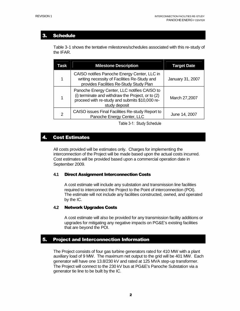
3. Schedule
Table 3-1 shows the tentative milestones/schedules associated with this re-study ofthe IFAR.
Task Milestone Description Target Date
1CAISO notifies Panoche Energy Center, LLC in
writing necessity of Facilities Re-Study andprovides Facilities Re-Study Study Plan
January 31, 2007
1
Panoche Energy Center, LLC notifies CAISO to(i) terminate and withdraw the Project, or to (2)proceed with re-study and submits $10,000 re-
study deposit
March 27,2007
2CAISO issues Final Facilities Re-study Report to
Panoche Energy Center, LLC June 14, 2007
Table 3-1: Study Schedule
4. Cost Estimates
All costs provided will be estimates only. Charges for implementing theinterconnection of the Project will be made based upon the actual costs incurred.Cost estimates will be provided based upon a commercial operation date inSeptember 2009.
4.1 Direct Assignment Interconnection Costs
A cost estimate will include any substation and transmission line facilitiesrequired to interconnect the Project to the Point of interconnection (POI).The estimate will not include any facilities constructed, owned, and operatedby the IC.
4.2 Network Upgrades Costs
A cost estimate will also be provided for any transmission facility additions orupgrades for mitigating any negative impacts on PG&E’s existing facilitiesthat are beyond the POI.
5. Project and Interconnection Information
The Project consists of four gas turbine generators rated for 410 MW with a plantauxiliary load of 9 MW. The maximum net output to the grid will be 401 MW. Eachgenerator will have one 13.8/230 kV and rated at 125 MVA step-up transformer.The Project will connect to the 230 kV bus at PG&E’s Panoche Substation via agenerator tie line to be built by the IC.

REVISION 1 INTERCONNECTION FACILITIES RE-STUDY
PANOCHEENERGY CENTER
3
Figure 5-1 provides the map for the Project and the transmission facilities in thevicinity. A conceptual one-line diagram of the Project is shown in Figure 5-2.
Figure 5-1: Map of the Project
Figure 5-2: Conceptual One-Line Diagram
P A N O C H EW / O P A N O C H E R O A D . 2 M I E / O H W Y 5
M E N D O T A9 3 6 4 0
O w n e r : P G EG I S _ I D : 7 1 5 2 1
S A P F u n c t L o c # : E T S . 1 1 . 1 0 1 3 6
P A N O C H EW / O P A N O C H E R O A D . 2 M I E / O H W Y 5
M E N D O T A9 3 6 4 0
O w n e r : P G EG I S _ I D : 7 1 5 2 1
S A P F u n c t L o c # : E T S . 1 1 . 1 0 1 3 6
P A N O C H EW / O P A N O C H E R O A D . 2 M I E / O H W Y 5
M E N D O T A9 3 6 4 0
O w n e r : P G EG I S _ I D : 7 1 5 2 1
S A P F u n c t L o c # : E T S . 1 1 . 1 0 1 3 6
P A N O C H EW / O P A N O C H E R O A D . 2 M I E / O H W Y 5
M E N D O T A9 3 6 4 0
O w n e r : P G EG I S _ I D : 7 1 5 2 1
S A P F u n c t L o c # : E T S . 1 1 . 1 0 1 3 6
P A N O C H EW / O P A N O C H E R O A D . 2 M I E / O H W Y 5
M E N D O T A9 3 6 4 0
O w n e r : P G EG I S _ I D : 7 1 5 2 1
S A P F u n c t L o c # : E T S . 1 1 . 1 0 1 3 6
W E L L H E A D P O W E R P A N O C H E4 3 6 4 9 W P A N O C H E R O A DM E N D O T A9 3 6 4 0O w n e r : n o n P G EG I S _ I D : 7 2 4 6 1S A P F u n c t L o c # :
W E L L H E A D P O W E R P A N O C H E4 3 6 4 9 W P A N O C H E R O A DM E N D O T A9 3 6 4 0O w n e r : n o n P G EG I S _ I D : 7 2 4 6 1S A P F u n c t L o c # :
W E L L H E A D P O W E R P A N O C H E4 3 6 4 9 W P A N O C H E R O A DM E N D O T A9 3 6 4 0O w n e r : n o n P G EG I S _ I D : 7 2 4 6 1S A P F u n c t L o c # :
W E L L H E A D P O W E R P A N O C H E4 3 6 4 9 W P A N O C H E R O A DM E N D O T A9 3 6 4 0O w n e r : n o n P G EG I S _ I D : 7 2 4 6 1S A P F u n c t L o c # :
W E L L H E A D P O W E R P A N O C H E4 3 6 4 9 W P A N O C H E R O A DM E N D O T A9 3 6 4 0O w n e r : n o n P G EG I S _ I D : 7 2 4 6 1S A P F u n c t L o c # :
L OS
BANO
S -PAN
OC
HE
#1 +- 200 74-
23 0kV
GAT
ES-P
ANO
CHE
#2- 2004 2-
230kV
PAN
OCH
E-H ELM
+-2 0109 -
2 30k V
CH
ENE
Y# 1
TAP
- 1025 5
A -1
15kV
P AN O C H E -ME N D O T A
- 10 25 5 - 1 1 5 k V
PAN
OC
HE
-ORO
L OM
A- 10
256-1 15
kV
WP A N O C H E R D
WP A N O C H E R D
WP A N O C H E
R D
WP A N O C H E
R D
WP A N O C H E R D
PANOCHE ENERGYCENTER PROJECT
GENERATORTIE LINE
230 kV BUS
New bus extension &Relocate the Panoche-Helm 230 kV line
P A N O C H EW / O P A N O C H E R O A D . 2 M I E / O H W Y 5
M E N D O T A9 3 6 4 0
O w n e r : P G EG I S _ I D : 7 1 5 2 1
S A P F u n c t L o c # : E T S . 1 1 . 1 0 1 3 6
P A N O C H EW / O P A N O C H E R O A D . 2 M I E / O H W Y 5
M E N D O T A9 3 6 4 0
O w n e r : P G EG I S _ I D : 7 1 5 2 1
S A P F u n c t L o c # : E T S . 1 1 . 1 0 1 3 6
P A N O C H EW / O P A N O C H E R O A D . 2 M I E / O H W Y 5
M E N D O T A9 3 6 4 0
O w n e r : P G EG I S _ I D : 7 1 5 2 1
S A P F u n c t L o c # : E T S . 1 1 . 1 0 1 3 6
P A N O C H EW / O P A N O C H E R O A D . 2 M I E / O H W Y 5
M E N D O T A9 3 6 4 0
O w n e r : P G EG I S _ I D : 7 1 5 2 1
S A P F u n c t L o c # : E T S . 1 1 . 1 0 1 3 6
P A N O C H EW / O P A N O C H E R O A D . 2 M I E / O H W Y 5
M E N D O T A9 3 6 4 0
O w n e r : P G EG I S _ I D : 7 1 5 2 1
S A P F u n c t L o c # : E T S . 1 1 . 1 0 1 3 6
W E L L H E A D P O W E R P A N O C H E4 3 6 4 9 W P A N O C H E R O A DM E N D O T A9 3 6 4 0O w n e r : n o n P G EG I S _ I D : 7 2 4 6 1S A P F u n c t L o c # :
W E L L H E A D P O W E R P A N O C H E4 3 6 4 9 W P A N O C H E R O A DM E N D O T A9 3 6 4 0O w n e r : n o n P G EG I S _ I D : 7 2 4 6 1S A P F u n c t L o c # :
W E L L H E A D P O W E R P A N O C H E4 3 6 4 9 W P A N O C H E R O A DM E N D O T A9 3 6 4 0O w n e r : n o n P G EG I S _ I D : 7 2 4 6 1S A P F u n c t L o c # :
W E L L H E A D P O W E R P A N O C H E4 3 6 4 9 W P A N O C H E R O A DM E N D O T A9 3 6 4 0O w n e r : n o n P G EG I S _ I D : 7 2 4 6 1S A P F u n c t L o c # :
W E L L H E A D P O W E R P A N O C H E4 3 6 4 9 W P A N O C H E R O A DM E N D O T A9 3 6 4 0O w n e r : n o n P G EG I S _ I D : 7 2 4 6 1S A P F u n c t L o c # :
L OS
BANO
S -PAN
OC
HE
#1 +- 200 74-
23 0kV
GAT
ES-P
ANO
CHE
#2- 2004 2-
230kV
PAN
OCH
E-H ELM
+-2 0109 -
2 30k V
CH
ENE
Y# 1
TAP
- 1025 5
A -1
15kV
P AN O C H E -ME N D O T A
- 10 25 5 - 1 1 5 k V
PAN
OC
HE
-ORO
L OM
A- 10
256-1 15
kV
WP A N O C H E R D
WP A N O C H E R D
WP A N O C H E
R D
WP A N O C H E
R D
WP A N O C H E R D
PANOCHE ENERGYCENTER PROJECT
GENERATORTIE LINE
230 kV BUS
New bus extension &Relocate the Panoche-Helm 230 kV line
102.5 MW
Panoche-Kearney230 kV
Los Banos-Panoche #2230kV
Coburn-Panoche230 kV
Los Banos-Panoche #1230 kV
Dos AmigosPP-Panoche230kV
PANOCHE SUBSTATION
230 kV Bus
230 kV Bus
102.5 MW 102.5 MW
PANOCHE ENERGYCENTER PROJECT
x
Point ofInterconnection
Generator Tie Line
102.5 MW
Gates-Panoche#1 230 kV
Gates-Panoche#2 230 kV
Panoche-Helm230 kV
Moss Landing-Panoche #2230kV
115 kV Bus
125MVA
New Bus Extension (2 bays)Relocate the Gates-Panoche#1 & 2 230 kV lines
125MVA
125MVA
125MVA
322312
NEW
202 282
242 232
272
252 262 332 212 222
Load
Install a new busParallel breakerin a spare bay
Add two new sectionalizingbreakers (utilize the bayvacated by the Gates-Panoche #1 230 kV line)
NEW
NEW
NEW
Add a new breaker for the interconnection (utilizethe bay vacated by the Gates-Panoche #2 230 kV line)
102.5 MW
Panoche-Kearney230 kV
Los Banos-Panoche #2230kV
Coburn-Panoche230 kV
Los Banos-Panoche #1230 kV
Dos AmigosPP-Panoche230kV
PANOCHE SUBSTATION
230 kV Bus
230 kV Bus
102.5 MW 102.5 MW
PANOCHE ENERGYCENTER PROJECT
x
Point ofInterconnection
Generator Tie Line
102.5 MW
Gates-Panoche#1 230 kV
Gates-Panoche#2 230 kV
Panoche-Helm230 kV
Moss Landing-Panoche #2230kV
115 kV Bus
125MVA
New Bus Extension (2 bays)Relocate the Gates-Panoche#1 & 2 230 kV lines
125MVA
125MVA
125MVA
322312
NEW
202 282
242 232
272
252 262 332 212 222
Load
Install a new busParallel breakerin a spare bay
Add two new sectionalizingbreakers (utilize the bayvacated by the Gates-Panoche #1 230 kV line)
NEW
NEW
NEW
Add a new breaker for the interconnection (utilizethe bay vacated by the Gates-Panoche #2 230 kV line)

REVISION 1 INTERCONNECTION FACILITIES RE-STUDY
PANOCHEENERGY CENTER
4
6. Study Assumptions
PG&E will conduct the IFAR using the following assumptions:
1. The Project consists of four gas turbine generators, and each is rated for 102.5MW. The total maximum total output is 410 MW with an expected total plantload of 9 MW. Therefore, the maximum net output to the grid is 401 MW.
2. The expected commercial operation date is September 2009.
3. The Project employs four step-up transformers and one for each generator.Each transformer is a three phase, 13.8/230 kV transformer, rated 75/100/125MVA (OA/FA/FA), and with an impedance of 10% at 75 MVA base.
4. The IC will engineer, procure, construct, and maintain its project facility.
5. The IC will engineer, procure, and construct the generator tie line (from theProject’s switchyard to Panoche Substation). The generator tie line is about1,000 feet long with 795 ACSS conductor or equivalent conductors.
6. This study will take into account the planned generating facilities andtransmission projects in PG&E’s service territory whose schedules areconcurrent with or precede the Project’s schedule.
7. System Impact Study Results
The ISIR issued on December 12, 2006 concluded that the Project would:
1) Exacerbate one normal pre-project overload:
The Borden-Gregg 230 kV Line
This line overloaded also as a result of a generation Project P0507with a superior queue position and an earlier online date. ProjectP0507 has been assigned the responsibility for mitigating thisoverload. However, should this project not materialize, the IC maybe responsible for mitigating this overload.
2) Cause one new Category B emergency overload:
The Wilson-Gregg 230 kV Line (section between Storey 1 andGregg).
The Project will provide mitigation.
3) Exacerbate five pre-project Category B emergency overloads.
4) Cause three new Category C overloads:

REVISION 1 INTERCONNECTION FACILITIES RE-STUDY
PANOCHEENERGY CENTER
5
The Coppermine-Tivy Valley 70 kV Line
The Herndon-Ashlan 230 kV Line (section between Figarden Tap 1and Ashlan)
The Wilson-Oro Loma 115 kV Line (section between LeGrand Jctand Wilson)
The Project will install Special Protection Schemes (SPS) to mitigate theseoverloads.
5) Exacerbate nine pre-project Category C emergency overloads
6) Overstress one 115 kV breaker (CB 112) and two 230 kV breakers (CB 222and 322) at Panoche Substation. A project with a superior queue positionand an earlier online date is currently responsible for replacing these threebreakers. However, should this project not materialize, the IC may beresponsible for replacing these breakers.
7) Cause minimal adverse transient performance impacts on the transmissionsystem.
8) Require the Project to install a fully redundant, double-pilot current differentialscheme for the 230 kV generator tie line as well as replacement of fourcurrents transformers (CTs) and their associated protective relays on four 230kV breakers at Panoche Substation.
8. Interconnection Facilities Re-study Scope
The IFAR will provide the cost estimates and work scope for: (1) Direct AssignmentFacilities required to interconnect the Project to the PG&E grid and (2) NetworkUpgrades to PG&E transmission facilities required to mitigate system impacts andinterconnect the Project. The specific studies conducted by the IFAR are:
8.1 Transmission Line Evaluation
8.1.1 Direct Assignment
The IC will construct its project facility and the generator tie line. Thetransmission line evaluation will provide work scope and cost estimatesfor the interconnection from the generator tie line to the 230 kV systemat Panoche Substation.
8.1.2 Network Upgrades
The transmission line evaluation will provide the work scope and costestimates for any required transmission line work that is beyond theInterconnection Point of the Project. This includes but is not limited tore-conductoring:

REVISION 1 INTERCONNECTION FACILITIES RE-STUDY
PANOCHEENERGY CENTER
6
the Wilson-Gregg 230 kV Line Section between Storey 1 andGregg (about 1 mile)
Relocate the Gates-Panoche #1 and #2 230 kV lines
8.2 Substation Evaluation
8.2.1 Direct Assignment
The Project’s substation will be constructed and owned by the IC,therefore, no cost estimates or work scope will be provided in the IFARfor this substation. The substation shall incorporate the requiredrelaying as specified in the PG&E interconnection handbook perSection G2.1. Note that there is a redundancy requirement for theapplication of multifunction relays. Direct assignment costs include, butare not limited to:
Install a new 230 kV breaker for the interconnection of theProject
Install a fully redundant, double-pilot current differentialscheme.
Pre-parallel inspection, testing, SCADA, EMS setup, andengineering support at the Project facility
8.2.2 Network Upgrades
The substation evaluation will provide the work scope and costestimates for any required substation work that is beyond theInterconnection Point of the Project. This includes but is not limited to:
Extend the 230 kV bus and relocate breakers for the Gates-Panoche #1 and #2 230 kV lines
Install two 230 kV bus sectionalization breakers
Replace four currents transformers (CTs) and their associatedprotective relays on four 230 kV breakers at PanocheSubstation
Install three SPSs to mitigate the Category C emergencyoverloads
Communication upgrade

REVISION 1 INTERCONNECTION FACILITIES RE-STUDY
PANOCHEENERGY CENTER
7
8.3 Land Evaluation
8.3.1 Direct Assignment
PG&E’s Corporate Real Estate Department will determine the newland rights required for the Project, and if any new land rights and/oreasements that might be required for the interconnection of the DirectAssignment facilities of the Project.
8.3.2 Network Upgrades
PG&E’s Corporate Real Estate Department will determine the newland rights required for the Project, and if any new land rights and/oreasements that might be required for the interconnection of theNetwork Upgrade facilities of the Project. This includes but is notlimited to:
Extend the 230 kV bus
Relocate the Gates-Panoche #1 and #2 230 kV lines
Reconductoring the Wilson-Gregg 230 kV Line Sectionbetween Storey 1 and Gregg
9. Environmental Evaluation/Permitting
9.1 CPUC General Order 131-D
PG&E is subject to the jurisdiction of the California Public UtilitiesCommission (CPUC); and must comply with CPUC General Order 131-D(Order) on the construction, modification, alteration, or addition of all electrictransmission facilities (i.e., lines, substations, switchyards, etc.). Thisincludes facilities to be constructed by others and deeded to PG&E. In mostcases where PG&E’s electric facilities are under 200 kV and are part of alarger project (i.e., electric generation plant), the Order exempts PG&E fromobtaining an approval from the CPUC provided its planned facilities havebeen included in the larger project’s California Environmental Quality Act(CEQA) review, the review has included circulation with the StateClearinghouse, and the project’s lead agency (i.e., California EnergyCommission) finds no significant unavoidable environmental impacts. PG&Eor the project developer may proceed with construction once PG&E has filednotice with the CPUC and the public on the project’s exempt status, and thepublic has had a chance to protest PG&E’s claim of exemption. If PG&Efacilities are not included in the larger project’s CEQA review, or if the projectdoes not qualify for the exemption, PG&E may need to seek approval fromthe CPUC (i.e., Certificate of Public Convenience and Necessity or Permit toConstruct) taking as much as 18 months or more since the CPUC wouldneed to conduct its own environmental evaluation (i.e., Negative Declarationor Environmental Impact Report).

REVISION 1 INTERCONNECTION FACILITIES RE-STUDY
PANOCHEENERGY CENTER
8
PG&E recommends that the project proponent include PG&E facility work inits project description and application to the lead agency performing CEQAreview on the project. The lead agency must consider the environmentalimpacts of the interconnection electric facility, whether built by the developerwith the intent to transfer ownership to PG&E or to be built and owned byPG&E directly, and make a finding of no significant unavoidableenvironmental impacts from construction of those facilities. Once the projecthas completed the review process and the environmental document (i.e.,Negative Declaration or Environmental Impact Report) finds no significantunavoidable environmental impacts from PG&E’s work, PG&E would file anAdvice Letter with the CPUC and publish public notice of the proposedconstruction of the facilities. The noticing process takes about 90 days if noprotests are filed, but should be done as early as possible so that a protestdoes not delay construction. PG&E has no control over the time it takes theCPUC to respond when issues arise. If the protest is granted, PG&E maythen need to apply for a formal permit to construct the project (i.e., Certificateof Public Convenience and Necessity or Permit to Construct). Facilities builtunder this procedure must also be designed to include consideration ofelectric and magnetic field (EMF) mitigation measures pursuant to PG&E“EMF Design Guidelines of New Electrical Facilities: Transmission,Substation and Distribution”.
Please see Section III, in General Order 131-D. This document can be foundin the CPUC’s web page at:
http://www.cpuc.ca.gov/PUBLISHED/GENERAL_ORDER/589.htm
9.2 CPUC Section 851
Because PG&E is subject to the jurisdiction of the CPUC, it must also complywith Public Utilities Code Section 851. Among other things, this codeprovision requires PG&E to obtain CPUC approval of leases and licenses touse PG&E property, including rights-of-way granted to third parties forinterconnection facilities. Obtaining CPUC approval for a Section 851application can take several months, and requires compliance with theCalifornia Environmental Quality Act (CEQA). PG&E recommends thatSection 851 issues be identified as early as possible so that the necessaryapplication can be prepared and processed.
10. Re-study
The IFAR was performed according to the assumptions shown in the Section titled“Study Assumptions.” In the event that these assumptions are changed, a re-studyaccording to the LGIP may be required to re-evaluate the Project’s impact onCAISO Controlled Grid. The IC would be responsible for paying for any such studyupdate.

REVISION 1 INTERCONNECTION FACILITIES RE-STUDY
PANOCHEENERGY CENTER
9
11. Stand-by Power
This study does not address any requirements for stand-by power that the Projectmay require. The IC should contact their Generation Interconnection Servicesrepresentative regarding this service.
Note: The IC is urged to contact their Generation Interconnection Services representative promptlyregarding stand-by service in order to ensure its availability for the Project’s start-up date

AppendixB
Panoche Energy Center ProjectSubstation Work Scope

APPENDIX B - 1
Preliminary Substation Work ScopeFor
Panoche Energy Center Project
5/10/07
Notes:
1. This proposed preliminary substation scope is based on the Facilities Re-study Plan,Protection Department’s protection requirements of 5/10/07
2. Forecast Power Plant in-service date is September, 2009
Panoche Substation
The existing 230kV system is a double-bus, single breaker configuration and currently has 11230kV line circuits without bus sectionalizing breakers. PG&E currently is initiating a reliabilityproject to install a new MPAC building to replace the existing control building and at the same timedo some upgrades or changes to the existing 230kV system. Depending on how much workPG&E will be able to do prior to this generation interconnection project, the scope of this generationproject may vary. The generation project scope may consist of Part 1 only, or both Part 1 and allor part of Part 2 as described below
Part 1:Part 1 scope covers the generation interconnection. Scope of Part 1 includes:
Install a new 230kV line breaker position at the location vacated by the re-location of Panoche-Gates Line No. 2.The new line breaker position is for the new generation-tie line.
Install the two levels of line current differential protection scheme specified by PG&E ProtectionEngineer. This protection scheme requires the installation of fiber for communication betweenPanoche Substation and the Panoche Energy Center
Part 2:Part 2 assumes that PG&E has installed an MPAC building to replace the existing control buildingand has also replaced or upgraded line protective relays at remote terminals. This Part 2 furtherassumes that the scope specified hereunder was not done prior to the start of this generationinterconnection project. The following is a description of the scope for Part 2
Purchase approx 320 ft x 300 ft of land on the SW side of the substation (MPAC Project Scope)
Extend the existing 230kV double buses by two bays to relocate Gates-Panoche 230kV Lines 1and 2. Installation will include
Eight (8) 230kV low profile bus support steel for new extended 230kV buses (MPAC ProjectScope)

APPENDIX B - 2
Four (4) 230kV bus selector switches each on a low profile support structure (MPAC ProjectScope)
Four (4) 230kV breaker disconnect switches each on a low profile support structure (MPACProject Scope)
Two (2) 55ft H x 50ft W pull off structure for the double busses (MPAC Project Scope) Two (2) 40ft H x 50ft W switch support and pulloff/dead-end structures, one for the relocated
Gates-Panoche Line #1 and the other, Gates-Panoche Line #2 (MPAC Project Scope) Two (2) new 230kV SF6 gas breakers (MPAC Project Scope) Two (2) 230kV line traps for the Gates-Panoche Lines #1 and #2 (MPAC Project Scope) Six (6) 230kV CCVT’s for the two lines and 12 230kV CCVT’s for the two bus sections (D and
E) on each bus. New protective relays inside the MPAC building per Protection Engineer’s requirements
Remove breaker CB 232 (Old Gates-Panoche Line #1), breaker disconnect and bypassswitches SW 235, 231, 233 and bus selector switches 237 and 239 and 230kV line trap tomake room for two bus sectionalizing breakers. Install in the bay so vacated two 230kV, 3000ACC, SF6 gas circuit breakers each with a pair of 3000 ACC disconnect switches, and a totalof 4 sets of 230kV CCVT’s (12 CCVT’s in all. Also these CCVT’s can be located along thebusses on more convenient spots). Note: the width of the bay is only 50 feet and it isextremely tight space because normally bus sectionalizing breakers require a width of 70 to 75feet.
After splitting the buses, install one 230kV bus parallel breaker on the section on the northside, using the existing spare bay. This installation includes: one breaker, five disconnectswitches (2 breaker disconnect, one bypass and two bus selector switches), one 55 ft tallswitch support structure and two low-profile switch support structures. And also protectiverelays inside the MPAC building. This parallel breaker should be installed in advance of thebus sectionalizing breakers.
Panoche Energy Center’s Switchyard
Review protection and revenue metering design and install revenue meter
Provide pre-parallel inspection and witness testing
Review SCADA and EMS design and provide telecom support for EMS telemetry and SCADA
PG&E’s ECC (Los Banos) and SFGO TOC
Install telecom equipment for EMS telemetry and SCADA

AppendixC
Panoche Energy Center ProjectProtection Requirements

APPENDIX C - 1
PANOCHE ENERGY CENTER PROJECT
SYSTEM IMPACT STUDY
FINAL PROTECTION REQUIREMENTS
REVISED 05-05-07
The following Protection Requirements are for estimating purposes only of the PanocheEnergy Center (Panoche EC) Project. The actual relays specified in the final protectionrequirements may differ from those outlined in this document.
Per Section G2.1 of the PG&E Interconnection Handbook, PG&E protectionrequirements are designed and intended to protect PG&E’s system only. GenerationEntity is responsible for the protection of its own system and equipment and must meetthe requirements in the PG&E Interconnection Handbook.
ASSUMPTIONS:
1) The Panoche EC will consist of four gas turbine generators each rated at 102.5MWwith a plant auxiliary load of 9 MW. Each generator will have its own GSU rated at125MVA. The maximum net output to the Grid will be 401 MW.
2) This generation will be connected to the 230kV bus at Panoche Substation viaapproximately 1000 feet of 795 ACSS conductor.
3) The existing Panoche 230kV bus configuration is a double bus single breakerconfiguration. It is proposed to install a 230KV MPAC Building at Panoche andrearrange the 230KV double bus to accommodate the new incoming 230kvline for the Panoche Energy Center.
4) Due to the very short length of the overhead 230kV interconnection betweenPanoche Substation and Panoche EC, a fully redundant, double-pilot currentdifferential protection scheme utilizing dual fiber optic communications will berequired to achieve coordination with all lines connected to the 230kV bus atPanoche Substation.
Note: PG&E does not recommend using over-current protection for this tie line. Tocoordinate with the lines into the 230 kV bus at Panoche Substation, it would benecessary to set the over-current relay with instantaneous protection. This relaywould operate instantaneously for faults on the generation tie line and in thegeneration facility. In case of faults within the facility, faults will be cleared by boththe facility protective devices and the remote tie line breaker resulting in theunnecessary loss of the whole generation facility. This will, also, prevent accuratefault location and cause delays in restoration of the generation facility for faults onthe tie line and within the facility.
5) The D60 and 311C relay requirements are Non-Integrated solutions; thus requiringdiscrete breaker failure and recloser relays to be installed.

APPENDIX C - 2
6) These protection requirements will not cover special protection set-ups fortemporary transmission line shoo-fly configurations that may be necessary tocomplete this project.
7) Line relays specified are per existing System Protection list of relays approved forpurchase. Existing Engineering Design Standards are associated with applicationof these relays.
8) Relay coordination was not reviewed for this study. Recoordination studies couldresult in the required replacement of relays that are determined to be out of rangeas a result of this interconnection.
9) Study is based upon existing information available, any changes to theinterconnection queue, connection point, or project information will result in arestudy of the area.
PROTECTION REQUIREMENTS
The Protection Requirements will consist of a fully redundant, double-pilot currentdifferential scheme utilizing dual fiber optic communications for the Panoche – PanocheEC 230KV Line. Due to the interconnection of the Panoche EC four terminals on thePanoche 230kV bus will require relay replacement due to CT Saturation. The detailsare as follows:
COMMUNICATIONS
Install dual redundant fiber optic cables between Panoche 230 kV substation andPanoche EC.
PANOCHE SUBSTATION
The interconnection of the Panoche EC to the Panoche 230kV bus will expose thefollowing Panoche 230 kV breakers (CB 212, CB 222, CB 332 and CB 322) to CTsaturation. These terminals will require the CTR to be raised and the relays to bereplaced. This may require replacement of relays at the remote terminals.
In addition, the Panoche 230kV breakers do not have Breaker Failure protection. Dueto this project remote terminal sensitivity will be decreased requiring all Panoche 230KVCBs to have Breaker Failure relays installed as part of this project. Due to theinstallation of a 230KV MPAC building at Panoche existing breaker CT saturationand resulting relay problems caused by the Panoche EC will be mitigated by theMPAC project. Please refer to the attached Preliminary MPAC ProtectionRequirements for the Panoche 230kV. However, if the MPAC Project iscancelled, the associated CT saturation and relay concerns would need to be theresponsibility of the Panoche EC. Breaker Failure, line protection, busprotection, are detailed in the end of this Appendix the MPAC Project Scope.
1. CB AAA: Panoche– Panoche EC 230KV Line
Line Length: Approximately 1000 feet

APPENDIX C - 3
CB AAA: Install one-230kV SF6 circuit breakers with bushing CTs rated3000/5 per PG&E specifications.
All CTs to be pulled into the control room.
Install G.E. L90 SET A current differential relay as one terminal of athree-terminal Panoche – Panoche EC pilot scheme using dual fiberoptic communication line. Per MPAC Standard.
Wire to outermost Bus-side CT.
Install SEL 311 L SET B current differential relay as one terminal of athree-terminal Panoche – Panoche EC pilot scheme using dual fiberoptic communication line. Per MPAC Standard.
Wire to innermost Bus-side CT.
All reclosing and breaker failure requirements are addressed in detailvia the MPAC protection requirements.
2. Parallel Breaker CB 202
If substitution for CB AAA is required by customer, PG&E will utilizeOvercurrent protection for the tie line. To coordinate with the lines into Panoche230kV substation, it would be necessary to set the Overcurrent relay withinstantaneous protection. This relay would operate instantaneously for faults onthe generation tie line and in the generation facility. In case of faults within thefacility, faults will be cleared by both the facility protective devices and theremote tie line breaker resulting in the unnecessary loss of the wholegeneration facility. This will, also, prevent accurate fault location and causedelays in restoration of the generation facility for faults on the tie line and withinthe facility. CB 202 will be installed per the 230kV MPAC Protectionrequirements.
PANOCHE EC FACILITY
1. CB BBB/CCC: Panoche– Panoche EC230KVLine
Line Length: Approximately 1000 feet
CB BBB: Install one-230kV SF6 circuit breakers with bushing CTs rated3000/5 per PG&E specifications.
CB CCC: Install one-230kV SF6 circuit breakers with bushing CTs rated3000/5 per PG&E specifications.
All CTs to be pulled into the control room.
Install two G.E. L90 SET A current differential relay, one dedicated toeach CB as two terminals of a three-terminal Panoche – Panoche ECpilot scheme using dual fiber optic communication line.
Wire to outermost Bank-side CT from both CBs.

APPENDIX C - 4
Install SEL 311 L SET B current differential relay, one dedicated to eachCB as two terminals of a three-terminal Panoche – Panoche EC pilotscheme using dual fiber optic communication line.
Wire to innermost Bank-side CT from both CBs.
Install Basler -BPR breaker failure relay on CB BBB
Install Basler -BPR breaker failure relay on CB CCC
Install three (3) line-side CCVTs to provide polarizing potentials for lineprotection and station automatics.
Install one (1) bank-side CCVTs on each transformer to providesynchronizing potential for station automatics
AppendixD
Panoche Energy Center ProjectTelecommunication Requirement

APPENDIX D - 1
Preliminary Panoche Energy Center ProjectTelecommunication Requirements
The following Information Systems and Technical Services (ISTS) requirements are forestimating purposes only for the Panoche Energy Center and are base on preliminaryprotection requirements dated 05/2007. The actual relays specified in the final protectionrequirements may differ from those outlined in this document.
GENERAL: PG&E shall design and install the communication system to implementtransfer trip schemes and line protection schemes. Any construction outside of PanocheSubstation will be the responsibility of the Panoche Energy Center.
F2.1 EMS/SCADA Telemetering
Telemetering signals must be transmitted via telephone company leased circuitsbetween the Panoche Energy Center and the responsible PG&E Electric ControlCenter (MPAC Building). With an output of 401 MW, the Panoche Energy Centerwill require a single SCADA circuit and redundant EMS circuits. Currently, there isa plan to install Modular Protection Automation Control (MPAC) Building atPanoche Substation prior to the connection of the Panoche Energy Center, and thedevelopment of the MPAC will include the necessary equipment needed to supportmost communication needs on the PG&E side.
As a significant note to any costing at this site is that there is an issue with any newtelephone pair requirements through AT&T. In order to meet any new AlternateEMS communication requirements there will need to be another project or studyestablished for the installation of microwave radio, fiber to California Department ofWater and Energy or a new commercial cable from AT&T. If the phone cableissues are resolved, any new EMS lease and modem could be terminated usingthe existing HVP equipment and RTU to provide telemetry data for the PanocheEnergy Center thereby eliminating the need for an additional RTU howeveradditional cards may have to be purchased.
REMOTE TERMINAL UNIT (RTU): PG&E will be responsible for the configurationof the RTU and will supervise the final functional testing of the RTU with the masterstation. The Panoche Energy Center shall be responsible for bringing in thecontrol, analog, and status inputs from the Panoche Energy Center circuit breakersto the RTU. If a new RTU is required it will be the responsibility of the PanocheEnergy Center to purchase and install that item.
F2.2 Protection
Preliminary protection requirements call for redundant fiber optic cables fromPanoche Substation to the Panoche Energy Center. Requirement is for two newfiber optic cables to be installed in two separated underground conduits by at leasta 10 foot separation (routes to be determined) between the Panoche EnergyCenter and Panoche Substation. This will ensure better survivability in the event ofa dig-in or other cable failure. Fiber optic cables entry into the substation and thePanoche Energy Center will use pull boxes.

APPENDIX D - 2
CONDUITS: Two communication conduits shall be 4-inch non metallic direct burial.The Panoche Energy Center will install two buried conduits 10’ apart from eachother from the Panoche Energy Center to Panoche Substation fence, place to bedesignated by PG&E. PG&E will install two conduits and two pull boxes from thefence line meeting position to the MPAC Building.
COMMUNICATION CABLES: PG&E will supply and the Panoche Energy Centerto install two fiber optic cables between outside the fence of Panoche Substationand the Panoche Energy Center. The fiber optic cables will be routed inside buriedconduits. PG&E shall pull fiber optic cables from their pull box to fiber distributionunit (FDU) inside the MPAC Building.
Fiber Optic Cable Termination/Testing: PG&E ISTS will test and terminate thefiber optic cables at both the Panoche Energy Center and the MPAC Building.
F2.3 Business Telephone
A business telephone is required at the locations of TT, telemetering, alarm, andmetering equipment, so that maintenance and repair work can be performedefficiently.
LEASE LINES: The Panoche Energy Center shall coordinate with AT&T toprovide telecom service to PG&E's metering. PG&E needs direct telecom servicefrom AT&T. A separate MPOE (Minimum Point of Entry) is needed for thePanoche Energy Center. The Panoche Center shall work with AT&T’s protectionengineers and outside plant engineers to ensure telecom entrance cable is properlyisolated against GPR voltages. A dedicated conduit route with pull boxes shall beapproved by AT&T and installed by the Panoche Energy Center. The PanocheEnergy Center shall provide ADC High voltage isolation jacks for AT&T cabletermination inside the PG&E metering shed. PG&E will provide and install SNCHigh Voltage isolation equipment in the metering shed. PG&E will install thecommunication cables between the PG&E metering shed and the PG&E controlroom or MPAC Building. PG&E will make the SCADA line connection to the RTUand provide the voice phone.
Contractor shall be responsible for placing orders for all required communicationlines as determined by PG&E. As a minimum there will be three business lines aprimary and alternate phone line supporting EMS data to Los Banos and one linefor voice communications.
G2.11 Remedial Action Scheme (RAS)
Equipment and related circuits required for participation in a RAS has not beenidentified nor included at this time.
ISTS Scope:
Panoche Energy Center
ISTS will assist with testing and acceptance of new Telephone Companyleased circuit.
ISTS will provide fiber optic cable specifications and installation requirements.

APPENDIX D - 3
ISTS will install fiber optic splice/patch panels, terminate, test and accept fiberoptic cables and jumpers used for protective relaying.
ISTS will install fiber interface for Tele-metering and connection to existingRTU.
ISTS will install SEL RS232 Fiber Transceivers and interconnection toexisting RTU.
ISTS will install new D20 Modem for Alternate EMS leased circuit. ISTS will assist with Database configuration.
Panoche Substation
ISTS will continue the installation of the underground Fiber Optic cable ISTS will install Fiber optic splice/patch panels, terminate, test and accept
fiber optic cables and jumpers used for protective relaying. Dual trenching is required and will be performed by substation department or
contractor for two conduit lines from fence to the new Panoche Energy Center
Los Banos Substation Switching Center
ISTS will assist with the RTSCADA Database configuration, testing andacceptance.
ISTS will assist with the installation, testing and acceptance of telephonecompany leased circuits.
ISTS will install telemetry modems, cabling and final connections to thePrimary and Alternate EMS systems.
ISTS will assist with the ESO EMS Database configuration, testing andacceptance.
Notes
There is a major issue with commercial phone service:
Commercial phone service is not easily available and may require AT&T to installanother multi pair cable down to the sub station; this expense is not in this study.Currently, there are about 12-15 circuit outages a year with the existing phone servicewith more than 24 hour downtime.
Alternative communications will be handled under a separate project request and isnot estimated under this study: Options include either Microwave communicationsapproximately $500K or fiber termination to California Department of Water andEnergy’s (the third party fiber) fiber network approximately $250K after negotiationsare settled.

APPENDIX D - 4
24 Strand Underground Fiber optic cableBuried and installed in independent conduit
24 Strand Underground Fiber optic cableBuried and installed in independent conduit
New Panoche EnergyCenter ,LLC, Cogen four
Turbine Generator
Fen
celine
divid
ingC
OG
EN
and
Pan
oche
New Panoche MPACBuilding
Approximately to planned site 1000' of fiberPurchased by PGE and installed by IC customer
Approx 200' to beinstalled by PGE
personnel and terminatedinto MPAC facility
Trenching is requiredRecommend two pull
boxes installed at fenceline
EM
SD
ata
Circ
uitt
ocl
oses
tsw
itchi
ngce
nter
Prim
ary
Lease lines from AT&T
Panoche Energy Center-Panoche SubProposed Protection & Telemetry
Communications
EMS
Dat
aC
ircui
tto
clos
ests
witc
hing
cent
erA
ltern
ate

APPENDIX D - 5

APPENDIX D - 6