California Underground Storage Tank Program - Facility ... Underground Storage Tank Program -...
23
UST Facility Compliance Inspection Handbook Part II - The Inspection [ Inspection ] [ Take Pictures ] [ Use a Checklist and Write a Field Inspection Report ] [ Include Esstential Elements in Your Inspection Report ] [ Looking at the Owner's Records ] [ What to Inspect at the Facility ] [ Automatic Tank Gauges (ATGs ] [ Galvanic System ] [ Impressed Current System ] [ Galvanic (sacrifical anode) Systems ] [ Impressed Current Systems ] [ Dispenser Areas ] [ Emergency Shut-off Switch [ Facility Plot Plan ] [ Ground Water Monitoring Wells ] [ Interstitial Monitors and Sump Sensors (including Dispenser Pan Sensor) ] [ Maintenance/Calibration Records ] [ Statistical Inventory Reconciliation (SIR) ] [ Dipsticking ] [ Manual Tank Gauging ] [ Monitoring Program ] [ Operating Permits ] [ Piping (Line) Leak Detection ] [ Pressurized Piping ] [ Suction Piping ] [ Both Suction and Pressurized Piping Systems ] [ Repair Records ] [ Emergency Response Plan ] [ Spill Containment and Overfill Prevention ] [ Overfill Prevention ] [ Audible and Visible Alarm ] Ball Float Valve or Float Vent Valve ] [ Automatic Shut-off Device ] [ Spill/Leak Reports ] [ Tank and Piping Integrity Tests ] [ For the Tank Test Part of the Report ] [ For the Piping Test Part of the Report ] [ Third-Party Evaluations ] Vapor or Vadose Zone Monitoring Wells ] California Underground Storage Tank Program - Facility Inspection Handbook - Part II - The Inspection file:///H|/ust/docs/handbook/part_2.html (1 of 23) [8/21/2000 1:46:20 PM]
Transcript of California Underground Storage Tank Program - Facility ... Underground Storage Tank Program -...
UST Facility Compliance Inspection HandbookPart II - The Inspection
[ Inspection ] [ Take Pictures ]
[ Use a Checklistand Write a FieldInspection Report
]
[ IncludeEsstential
Elements in YourInspection Report
]
[ Looking at the Owner's Records ][ What to Inspect at
the Facility ][ Automatic TankGauges (ATGs ]
[ GalvanicSystem ]
[ Impressed Current System ][ Galvanic (sacrifical
anode) Systems ][ Impressed
Current Systems ][ Dispenser Areas
]
[ Emergency Shut-off Switch [ Facility Plot Plan ][ Ground Water
Monitoring Wells]
[ InterstitialMonitors andSump Sensors
(includingDispenser Pan
Sensor) ]
[ Maintenance/Calibration Records ][ Statistical InventoryReconciliation (SIR) ]
[ Dipsticking ][ Manual Tank
Gauging ]
[ Monitoring Program ] [ Operating Permits ][ Piping (Line)
Leak Detection ][ Pressurized
Piping ]
[ Suction Piping ][ Both Suction andPressurized Piping
Systems ][ Repair Records ]
[ EmergencyResponse Plan ]
[ Spill Containment and OverfillPrevention ]
[ Overfill Prevention ][ Audible and
Visible Alarm ]
Ball Float Valveor Float Vent
Valve ]
[ Automatic Shut-off Device ] [ Spill/Leak Reports ][ Tank and PipingIntegrity Tests ]
[ For the TankTest Part of the
Report ]
[ For the Piping Test Part of the Report]
[ Third-PartyEvaluations ]
Vapor or Vadose Zone MonitoringWells ]
California Underground Storage Tank Program - Facility Inspection Handbook - Part II - The Inspection
file:///H|/ust/docs/handbook/part_2.html (1 of 23) [8/21/2000 1:46:20 PM]
Part II - THE INSPECTION
The whole point of doing an inspection is to find out if the tank owner is complying with USTregulations and to educate him about his responsibilities. Some of your inspections will be routine. Youknow the tank owner or operator. You know that he is interested in keeping his facility in order, and he’son the phone to you every week with a new question. You’ve been inspecting his facility regularly for 10years and he’s squeaky clean. It’s a pleasure having him in your jurisdiction.
But you also have problem facilities. These inspections may not be so routine. You’ll be on the lookoutfor disabled monitoring equipment, sloppy records, and general chaos that spells noncompliance. How doyou make a case that your district attorney will agree to pursue?
DocumentationTake Pictures
It’s hard to argue with the kind of evidence produced by a camera. Take some overall viewsand then take pictures of specific violations. As you take each picture, jot down in yournotebook the date, time, and the subject of the photo. Be sure to record these sequentially sothat when you have the photos developed, you won’t have trouble identifying each one.Transfer the information to labels, initial the labels, and then put them on the backs of thepictures. (By going this extra step, you avoid making pressure marks on your pictures.)
1.
Use a Checklist and Write a Field Inspection Report
Doing a thorough inspection without a checklist is not easy.
You may have been able to start filling out your list back at the office with informationabout the owner, address, phone, type of tanks, type of monitoring, etc. Then, when you’reat the facility, you can check your records against the owner’s records. You can use thechecklist as your final inspection report, or you can transfer the information from thechecklist to a formal report in narrative form. Use whatever works best for you and, at thesame time, gives you a complete inspection report.
We have included sample checklists at Appendix F. You may want to customize them to fityour needs or style, or you can contact other local agencies to see about using theirchecklists. Your agency may choose to develop a new checklist or use existing ones forprogram requirements. The use of a general checklist plus specific monitoring andconstruction checklists will enable even the most novice inspector to conduct a thoroughinspection.
2.
Include Esstential Elements in Your Inspection Report
Time and date■
Facility location, phone, and owner/operator name■
Upgrade compliance certificate number, operating permit number and expiration date■
Purpose of the inspection■
Names of people you interviewed and their titles or responsibilities (e.g., owner,■
3.
A.
California Underground Storage Tank Program - Facility Inspection Handbook - Part II - The Inspection
file:///H|/ust/docs/handbook/part_2.html (2 of 23) [8/21/2000 1:46:20 PM]
attendant, tank tester, etc.)
Type and size of tanks/piping and tank contents.■
Type of monitoring equipment.■
Dates monitoring equipment was serviced/calibrated.■
List of violations or areas where the owner is out of compliance. You can include thereferences to law or regulation or you can fill this in at the office.
■
Identification of previous violations and corrective action taken. You may want tonote these items only if your inspection is to see if previous violations have beencorrected.
■
Description of samples or evidence collected.■
Specific steps the owner must take to correct problems including deadlines forcompliance.
■
The time the inspection ended.■
Your signature.■
The signature of the person receiving a copy of the report. You may not always get asignature if you’ve just had a difficult inspection and interview. If the person youinterviewed refuses to sign your report, make a note: “Mr. Tank Operator refused tosign this report; a copy was left at the facility.”
■
It’s a good idea to make sure the tank owner receives a copy of your final inspection report -even if there were no violations.
Looking at the Owner’s Records [ H&SC 25293(a)and CCR 2712(b) ]
Finding out how well an operator is keeping his records is as important as inspecting hismonitoring equipment. You also need to see whether the information you were given matches theinformation kept by the operator. If you have the files with you or you filled out the inspectionchecklist back at the office, you’ll be able to find information gaps or other inconsistencies.
Owners are required to keep the operating permit and attachments (monitoring, response, and plotplans) on site. Monitoring, maintenance, repair, lining, and upgrade records may be onsite or atanother location (corporate office, for example.) Owners preferring to keep their records off siterequires that you plan ahead and schedule your visits.
To avoid misunderstandings, you might want to have the location of the records established in theoperating permit (this is not a regulatory requirement). If you permit off-site record keeping, besure to make an appointment for your inspections. Owners are allowed 36 hours to make theirrecords available to you.
Once you have the records, check to make sure the owner/operator has been implementing theapproved monitoring plan for the facility. For certain facilities, you will have to amend themonitoring plan because of new enhanced leak detection requirements for facilities located within1,000 feet of a well.
B.
California Underground Storage Tank Program - Facility Inspection Handbook - Part II - The Inspection
file:///H|/ust/docs/handbook/part_2.html (3 of 23) [8/21/2000 1:46:20 PM]
What to Inspect at the Facility
In this section, the records and equipment you may be looking at during an inspection are listedalphabetically. What you inspect will, of course, depend on the type of facility, tanks, product, andmonitoring equipment at the facility.
AUTOMATIC TANK GAUGES (ATGs) [ CCR 2643(b ]
ATGs are programmed to monitor volume changes in USTs. They consist of a panel on a wall andprobes that sense product level and temperature changes. (See Appendix F for checklist) ATGshave two modes: inventory mode and leak test mode.
When an ATG is in the inventory mode, it provides information about product level,volume, and temperature.
❍
When the ATG is in the leak test mode, it is checking for product level changes that mayindicate a leak.
❍
The ATG is normally in the inventory mode unless the operator is running a leak test.
Some ATGs are equipped with a software program to continuously collect product level andtemperature data from the tank. As soon as the system has gathered enough useable data, it willperform a leak test. These are referred to as Continuous Automatic Tank Gauges (CATG). Formore information on these refer to “A Guide to Understanding Automatic Tank Gauges”. CATGshave some hardware and some capabilities as ATGs.
Most ATGs come with alarms - leak detection alarms, high-product level alarms, low-productlevel alarms, high-water alarms, and theft alarms. ATGs can also be equipped with externalsensors (liquid and vapor), and line (piping) leak detectors.
Check the records for any alarms since your last inspection. If there is a record of alarms,what type of alarms were they? What action did the operator take?
❍
Check for frequent, unexplained high water alarms. This may indicate ground waterintrusion into the tank.
❍
Look for a monitoring box, typically located on an inside office wall, garage, or storagearea. Ask for a demonstration to see if it’s working. For example, ask to see a printout of thecurrent tank level for each tank.
❍
Look for the external part of the tank probe in an access manhole above each tank to seehow many tanks are hooked up to the ATG.
❍
Try to determine if someone has tampered with the system, preventing it from detecting aleak if one were to occur. Have the operator dispense a gallon of product from the tank tosee if the gallon loss registers on the monitoring box. Then have the operator add the g allonback into the tank to see if it registers.
❍
Ask enough questions to tell whether the owner/operator knows what the system does andhow it is supposed to work.
❍
C.
California Underground Storage Tank Program - Facility Inspection Handbook - Part II - The Inspection
file:///H|/ust/docs/handbook/part_2.html (4 of 23) [8/21/2000 1:46:20 PM]
Ask to see the manufacturer’s manual to see how the equipment is supposed to work, if youare uncertain about the system or the operator’s ability to use it. You could schedule ameeting with a maintenance person or vendor representative if you’re unsure about theequipment.
❍
Look to see if there is a leak test report for each tank for each month since your lastinspection. Did all the tanks pass? If not, what was done to investigate?
❍
Does the printout show time, date, tank identification number, fuel depth, water depth,temperature, liquid volume, length of the test, and calculated leak rate?
❍
Is the recorded leak rate on the printout (in gallons per hour) less than the ATG’s leakthreshold?
❍
Did the operator wait the appropriate amount of time after fuel delivery to begin the test?(See LG 113 for specification)
❍
Was the proper amount of product in the tank for the test? (See LG 113)❍
Was there any dispensing during the test? Check the beginning and ending product level tomake this determination. (See LG 113)
❍
The facility should have a written monitoring and maintenance plan that describes the equipmenttraining given to the operator at the time of installation. This would give you some idea of whattype of questions the operator should be able to answer.
Ask to see all of the monthly test results since your last inspection. The equipment could have hadproblems at some point in the interim. If so, repairs should have been made and the records shouldindicate this.
For an in-depth look at automatic tank gauges - how they work, what the regulatory requirementsare, what the maintenance requirements are - look at A Guide to Understanding Automatic TankGauges, published by the SWRCB. Fax your request for a copy to (916) 227-4349.
CATHODIC PROTECTION TESTING [ CCR 2635(a)(2), 2636(b) ]
Cathodic protection systems must be tested by cathodic protection testers within 6 months ofinstallation and then every 3 years.
A cathodic protection tester must re-evaluate the cathodic protection system within 6 months ofany construction on or within the vicinity of a cathodically-protected UST. This is to verify that nodamage was done to the electrical system.
Do the files contain evidence that the 3-year testing is being conducted for both the galvanicor impresses current systems? Is the rectifier for the impressed-current system checkedevery 60 days? Records pertaining to cathodic protection system maintenance must be kept6 1/2 years.
❍
Because cathodic testing reports completed by a cathodic protection tester are supposed to be keptin the facility’s file, some inspectors will rely on these reports to verify that corrosion protection
California Underground Storage Tank Program - Facility Inspection Handbook - Part II - The Inspection
file:///H|/ust/docs/handbook/part_2.html (5 of 23) [8/21/2000 1:46:20 PM]
exists and is working. Some hands-on inspectors who know about cathodic protection will checkthe system and perform structure-to-soil tests.
Definition of Cathodic Protection Tester
.....someone who can demonstrate an understanding of the principles and measurements ofcathodic protection systems... and who has education and experience in those systems as they
pertain to USTs.
CCR 2611(See LG 145)
There is no State certification for cathodic protection testers.
You won’t be able to verify the coating on the tank (because it’s buried), but you should be able toverify the type of cathodic protection used, whether there is electrical isolation between pump andpiping, and achievement of the -0.85 volt structure-to-soil performance criteria. Non-coateddispenser pans are usually protected by the piping CP system as long as there is electricalcontinuity between them.
Here’s what to look for during your inspection:
Every three years, the tester must perform the following evaluations for both galvanic andimpressed-current systems:
structure-to-soil voltage potential measurements1.
verification of isolation and continuity2.
Check test reports to see that cathodic protection monitoring has been performed by atrained cathodic protection tester every three years. (See Appendix G for test report form.)
■
GALVANIC SYSTEM (also known as sacrificial anode systems):
Structure-to-soil potential measurements must be taken every three years because they can changeduring the life of a UST.
Look for a test station where lead wires are accessible to you. Tank test stations should beover the top of each tank. In the absence of any test station, look for a lead wire at the fillpipe. At newer installations with spill containment, look near the submersible pump.
❍
To do the structure-to-soil test, use a volt meter and reference electrode to determinewhether the steel tank and piping meet -0.85 volts, the most commonly accepted standard ofcorrosion protection. Place the reference electrode in the soil or backfill. Measurementstaken through concrete or asphalt are inaccurate.
❍
Check for electrical isolation between the pump and piping; look for an isolating union. Ifthe galvanic cathodic protection system test records for piping are in order and there is no
❍
California Underground Storage Tank Program - Facility Inspection Handbook - Part II - The Inspection
file:///H|/ust/docs/handbook/part_2.html (6 of 23) [8/21/2000 1:46:20 PM]
electrical isolation, you might question those test results. Use a continuity tester to verifythat the pump and the piping are not electrically connected. For galvanic systems, the pumpand piping should be electrically isolated. And if the piping is steel, there should be anodesconnected to it for protection. The piping should also meet the -0.85 volt structure-to-soilcriteria.
If lead wires are nowhere to be found or if you can’t verify the cathodic protection testrecords, then require the owner to have the test done by a cathodic protection tester and theresults submitted to you within a reasonable period of time. Note on your checklist if youcan’t verify that the system is working.
❍
IMPRESSED CURRENT SYSTEM:
In addition to the 3-year evaluation performed by cathodic protection testers, rectifiers forimpressed-current cathodic protection systems must be checked at least every 60 days. Theregulations do not specify who does this 60-day inspection, so local agencies should have a policy.Will you allow an owner or operator to do the inspection as long as they know what they’re doing?Or will you require a maintenance person to do it? If appropriate, ask for a demonstration of theinspection process.
Look for a rectifier box on the office wall with a pilot light that indicates the electric currentis turned on.
❍
Check the voltage and amperage readings. Are they consistent with readings previouslyrecorded? Rectifiers usually contain volt meters and ammeters to monitor the system’sperformance. If the readings aren’t consistent, ask to see the service records and for anexplanation why the settings were changed.
❍
These readings should be recorded every 60 days (see Appendix G for a sample form for recordingthese readings).
Rectifier settings should be changed only by a corrosion engineer (or under his direction).Owners and operators should never move these dials or terminal connections.
TECHNICAL NOTES ON CATHODIC PROTECTION SYSTEMS
Galvanic (sacrificial anode) Systems
These systems are generally used on new double-wall steel coated USTs.
Pre-engineered galvanic cathodic protection systems have the following four interrelated methods
California Underground Storage Tank Program - Facility Inspection Handbook - Part II - The Inspection
file:///H|/ust/docs/handbook/part_2.html (7 of 23) [8/21/2000 1:46:20 PM]
for protecting the tank: dielectric coating, electrical isolation devices (e.g. nylon bushings andgaskets), sacrificial anodes, and test stations.
Sacrificial anodes make use of the natural difference of electrical potential between the anode andthe tank. These systems can protect only small areas of exposed metal and require separate anodesfor tank and piping (including dispenser containment).
Tanks protected with sacrificial anodes should be equipped with fittings for electrically isolatingthe different parts of the system (i.e., tank, piping, and especially the pump.) These fittings may benylon bushings, isolating unions, or bolted flanges. Without electrical isolation, the sacrificialanodes will attempt to protect anything that is electrically connected to the tank or piping, therebyshortening the life of the anodes.
Impressed Current Systems
This type of cathodic protection is generally applied to single-wall, steel USTs for upgrading.
The tank, piping and other components such as dispenser pans can be cathodically protected by animpressed current system in which the protective current is provided through the use of a rectifierwhich converts AC current to DC current. Impressed current systems can produce much largercurrent and can protect even bare steel tanks. For this reason, impressed current systems are mostcommonly used as a retrofit on existing bare steel tanks.
An impressed current system requires the same structure-to-soil measurement as a galvanicsystem. Good operating practice includes inspecting and recording the voltage and amperageoutputs of the rectifier every 60 days. (See Appendix G)
DISPENSER AREAS [ H&SC 25281.5 ]
Under every dispenser, the piping has a shut-off valve with a fusible link and a shear joint. (This isa Uniform Fire Code requirement.) These valves are known as “shear valves,” “impact valves,” or“earthquake valves.”
The name says it all. If the dispenser is jarred, these valves are supposed to shut off the flow ofproduct. If your agency’s policy allows hands-on inspections, you can check to see if the valveworks by flicking it open and closed while a customer is pumping fuel. (Let the operator and thecustomer know what you’re doing!)
Ask the operator to open all the panels on the front of the dispensers. They should be lockedand the operator should know where the keys are. California Air Resources Board inspectorsissue fines if keys are not available on site.
❍
California Underground Storage Tank Program - Facility Inspection Handbook - Part II - The Inspection
file:///H|/ust/docs/handbook/part_2.html (8 of 23) [8/21/2000 1:46:20 PM]
Look for leaks from fittings and elbows while a customer is filling his tank. Strong vapors orstained soil indicate there’s been leakage.
❍
Make sure any mechanical floats in secondary dispenser containment remain properlychained. (See Page 28)
❍
Dispenser calibration sticker - At retail stations, dispenser meter inspections are done bythe local Weights and Measures office. The inspector issues stickers to be placed on
dispensers that pass inspection. If the meter readings are off, the dispenser is tagged and theowner must have it calibrated before using it again. If the operator is monitoring his UST
using statistical inventory reconciliation and the meter readings are off, then the reconciliationwill be, too.
Dispensers at non-retail facilities should be checked by a qualified device repair person ifstatistical inventory reconciliation is used.
EMERGENCY SHUT-OFF SWITCH [ CCR 2632(d)(1) & 2711(a)(8) ]
The Uniform Fire Code requires every facility to have an electrical emergency shut-off switch.This electrical switch must be clearly labeled and installed within 25-75 feet of each dispenser.You can make sure the switch works properly by turning it on and off while someone dispensesfuel into a container or while a customer is pumping fuel. (Let the operator and the customer knowwhat you’re doing!)
FACILITY PLOT PLAN
When an owner prepares an operating permit application, he must include a plot plan of thefacility.
The diagram must include the location of the tanks and piping and any ancillary equipment.Ancillary equipment includes monitoring equipment and control panels, dispensers, overfillalarms, vent pipes, and fill pipes.
Check the operating permit and attached monitoring program (monitoring, response, andplot plan). Are they up to date?
❍
GROUND WATER MONITORING WELLS [ CCR 2648, 2649 ]
California Underground Storage Tank Program - Facility Inspection Handbook - Part II - The Inspection
file:///H|/ust/docs/handbook/part_2.html (9 of 23) [8/21/2000 1:46:20 PM]
Ground water monitoring detects the presence of product floating on the ground water. To ensurethat the system is suitable for the site, an assessment is required at installation. Geologic logs mustbe prepared by a professional geologist or civil engineer [CCR 2649(b)(1)(D)]. Wells are installedat strategic locations in the ground near the tank and along the piping runs. They should bechecked for the presence of free product by using a bailer at least every 30 days or by a permanentsensor that operates automatically and continuously.
Check the distribution of the monitoring wells. Are there enough wells to monitor the tanksand piping adequately? If it looks like the well distribution is sparse, ask to see a copy of thefacility site assessment used to determine the well locations.
❍
Check the monitoring records. If they look as if they were done all in one day, they probablywere.
❍
If wells are partially paved over or locks are rusted shut, the wells are obviously not beingsampled (a violation).
❍
Are the wells labeled clearly so that delivery truck drivers don’t mistakenly use them as fillpipes?
❍
Are the wells constructed to prevent contamination from surface runoff and infiltration?Water accumulating around the well is a good sign that the well is sealed. Be sure to bailthis water before you open the well.
❍
Check the well caps to see if they’re tight enough to keep out surface runoff.❍
Are the well caps secured to prevent tampering? If the caps are locked, is the key availableto the person responsible for monitoring?
❍
All monitoring well piping should be slotted. To verify this, you can run a narrow stick witha nail at the end along the inside of the pipe. Does it feel like there are slots? If there are noslots, ground water (and free product) can’t get into the pipe for monitoring.
❍
Check to make sure there is sufficient water in the well. An inch or two of water in the wellis not much use for monitoring purposes. On the other hand, if the water level is higher thanthe slots in the pipe, you will not detect free product.
❍
Ask if sampling is done by using a bailer or an automatic device. Verify that the properequipment is on site. Does the bailer look like it’s so new that it’s never been used? Ask theoperator for a demonstration, if necessary.
❍
If sampling is done by bailer, check the log to verify that it’s done at least weekly. If groundwater monitoring is done automatically check the control box (usually on the inside officewall) to be sure the power light is on and no alarm is indicated.
❍
It’s a good idea to have operators keep a log sheet next to the control box to record allalarms and the steps taken to clear them.
❍
INTERSTITIAL MONITORS AND SUMP SENSORS (INCLUDING DISPENSER PANSENSOR)[ CCR 2632(c)(2) ]
California Underground Storage Tank Program - Facility Inspection Handbook - Part II - The Inspection
file:///H|/ust/docs/handbook/part_2.html (10 of 23) [8/21/2000 1:46:20 PM]
Interstitial monitoring is any monitoring method that checks for leaks in the space between theprimary containment and the outer wall, or barrier. Product that leaks from the inner wall ofdouble-wall piping goes into the interstitial space and gathers in the sump, where an alarm goesoff. (See Appendix F for checklist)
Check the monitoring box in the office to see if the power light is on and the alarmindicators are off. Look for access boxes for the probes in the vicinity of the tanks and thepiping that are being monitored.
❍
To verify that double-walled piping is truly double-walled, check at both ends of the piping(pump sump end and dispenser end) to see if there are points where the piping increasessubstantially in size, or that piping and dispenser sumps are present.
❍
If the tank system has a liner with monitoring wells in the interstitial space (instead of adouble-walled tank), follow the same verification steps for monitoring wells listed under“Ground Water Monitoring Wells”.
❍
Look in all the piping sumps and under all dispensers. Sensors must be free of debris, dirt,and corrosion. Sumps and dispenser pan should be water-tight and sensors should be dry. Isthe sensor properly placed at the bottom of the low end of the sump or dispenser? If thesensor is set too high, leaked product could go undetected for a long time.
❍
If the sump sensor and dispenser pan sensor are the type that respond to liquid, you couldtake the sensor and dip it in hydrocarbon or water to see if the alarm triggers. If it is a floatsensor, you can turn it upside down to trigger the alarm. Or you could dip it in a container ofliquid (water or product) to see if the float moves up and triggers an alarm. There must be anaudible and visual alarm. Be sure to return the sensor to its proper position.
❍
If the sump sensor shuts down the turbine when a release is detected or if the monitoringsystem fails or is disconnected, no further monitoring is required. For more information onmonitoring requirements for double-walled piping see Table 11 of the UST guide on thewebsite http://www.swrcb.ca.gov/~cwphome/ust/
Some interstitial sensors are difficult to replace properly after you remove them, so becareful. You always have the option of having a maintenance person check the sensor whileyou watch. You could also have the operator do it if he’s been trained and knows what he’sdoing.
An alternative (a less reassuring one) to doing this yourself is to rely on annual certificationrecords. Often, the panel on the wall or a computer printout can give you the status ofsensors and alarm history. And, of course, you could always schedule a visit during annualcertification checks.
If you’re relying on records, you should still verify information by visually inspectingthe sensor line to make sure it’s running into the interstitial area of the tank.
■
❍
California Underground Storage Tank Program - Facility Inspection Handbook - Part II - The Inspection
file:///H|/ust/docs/handbook/part_2.html (11 of 23) [8/21/2000 1:46:20 PM]
Sumps and sensors installed after May5, 1994 must be third-party certified.
MAINTENANCE/CALIBRATION RECORDS [ H&SC 25293, CCR 2712(d), CCR2630(d) ]
Manufacturers of UST systems include recommended maintenance schedules in theiroperating manuals. These schedules must be maintained for five years from the date ofinstallation.
All records of routine maintenance and calibration must be kept on site in the facility’s filesfor at least three years.
Check to see if the owner is having his monitoring equipment serviced according tomanufacturer’s instructions. Regardless of the manufacturer’s schedule, check tomake sure the equipment is functioning properly as required once per year.
■
The annual certification must be done by properly trained personnel. Some manufacturerscertify their service people and recommend that only those people work on their systems.
Some local agency inspectors specify which maintenance companies may perform this typeof work.
Some local agency inspectors require the annual check to be performed in their presence.
STATISTICAL INVENTORY RECONCILIATION (SIR) [ CCR 2643(b)(3), 2646.1 ]
If the tank is monitored by statistical inventory reconciliation (SIR), the records should beon file. Inventory reconciliation records must be kept for three years. (See Appendix F forinspection checklist)
Check to see if the operator is gathering data correctly (daily pump meter readings,deliveries, and product level). Are his calculations accurate? Is he checking for waterdaily? Is there a drop tube in the fill pipe?
■
MIR is not allowed as a leak detection method (however, the operator may use it for1.
California Underground Storage Tank Program - Facility Inspection Handbook - Part II - The Inspection
file:///H|/ust/docs/handbook/part_2.html (12 of 23) [8/21/2000 1:46:20 PM]
his own inventory control).
Review monthly SIR results. Any reported failure requires a tank and/or piping test.Appendix D contains suggested SIR reporting forms. As indicated on the forms, testresults should be reported as, “pass,” “fail,” or “inconclusive”
Check to see if a tank integrity test has been performed within the last two years.
2.
See LGs 123-2, and 139-1 for more detailed information about SIR.
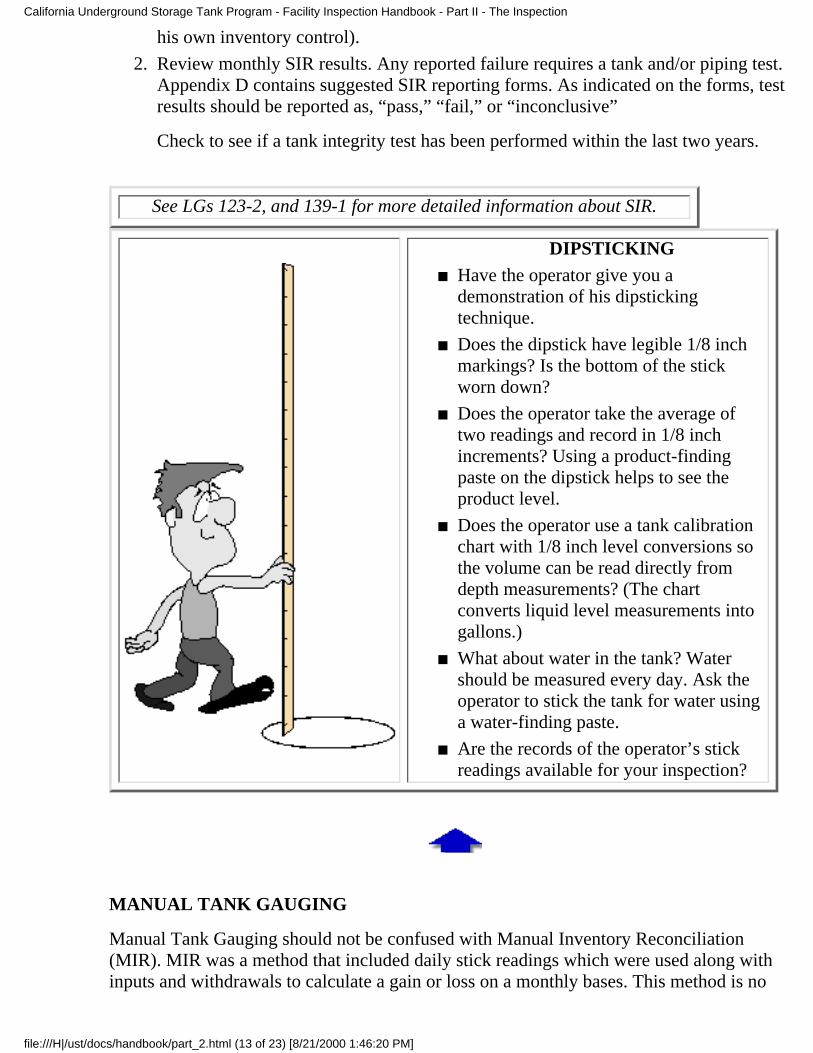
DIPSTICKINGHave the operator give you ademonstration of his dipstickingtechnique.
■
Does the dipstick have legible 1/8 inchmarkings? Is the bottom of the stickworn down?
■
Does the operator take the average oftwo readings and record in 1/8 inchincrements? Using a product-findingpaste on the dipstick helps to see theproduct level.
■
Does the operator use a tank calibrationchart with 1/8 inch level conversions sothe volume can be read directly fromdepth measurements? (The chartconverts liquid level measurements intogallons.)
■
What about water in the tank? Watershould be measured every day. Ask theoperator to stick the tank for water usinga water-finding paste.
■
Are the records of the operator’s stickreadings available for your inspection?
■
MANUAL TANK GAUGING
Manual Tank Gauging should not be confused with Manual Inventory Reconciliation(MIR). MIR was a method that included daily stick readings which were used along withinputs and withdrawals to calculate a gain or loss on a monthly bases. This method is no
California Underground Storage Tank Program - Facility Inspection Handbook - Part II - The Inspection
file:///H|/ust/docs/handbook/part_2.html (13 of 23) [8/21/2000 1:46:20 PM]
longer allowed.
The manual tank gauging method is done weekly after taking the tank out of service for acertain period of time. Liquid level readings (dipsticking) are taken at the beginning andending of the test period and compared with each other to see if the tank is leaking.
Tanks with a capacity up to and including 550 gallons may be monitored by thismethod alone.
■
Tanks with a capacity of 551 gallons up to and including 1,000 gallons may bemonitored by this method alone if the testing period is extended to 60 hours.
■
Manual tank gauging may not be used on piping or on tanks with secondarycontainment.
See LG 137-1, “Weekly Manual Tank Gauging” (a booklet for the tankowner) for more information.
■
Have the tank gauging readings (see dipsticking on page 32) been taken once a weekand over a minimum 36-hour period?
■
The tanks must be gauged twice and an average reading used in the calculations ofliquid volume. Are all these readings recorded? Is there a tank chart calibrated in 1/8inch increments?
■
Check the calculated differences in tank level readings: Are the weekly as well asmonthly average variations less than the allowable standards (Table 4.1 in Section2645 of the UST regulations)? If any of these readings are more than the allowablestandard, a leak is indicated.
■
MONITORING PROGRAM [ H&SC 25293, CCR 2632(b),(d), 2641(h) ]
When the owner originally applied for an operating permit, his application included awritten monitoring program.
The monitoring program consists of the
Monitoring plan■
Response plan■
Plot plan■
Each is required to be attached to or referenced in the operating permit. Referenceddocuments should be on-site and available to the facility employees.
Check the records for the monitoring program. They should be with the operatingpermit.
■
California Underground Storage Tank Program - Facility Inspection Handbook - Part II - The Inspection
file:///H|/ust/docs/handbook/part_2.html (14 of 23) [8/21/2000 1:46:20 PM]
See Appendix D for a sample monitoring program.
OPERATING PERMITS
Owners of USTs must have a facility operating permit that covers all tanks on a site. Thepermit must be kept at the facility for the operating life of the tank(s). All permit conditionsand attachments must be on site also. Some agencies require the permit to be posted.
Check the owner’s records for a copy of the operating permit. Does it look like theone in your records? Is it current or has it expired?
■
Has anything been changed (monitoring equipment, type of fuel being stored, name ofowner, etc.) that wasn’t reported to you or approved by you?
■
See Appendix B for a sample permit showing the required UST relatedinformation.
PIPING (LINE) LEAK DETECTION [ H&SC 25281.5, CCR 2636, 2643(c),(d),(e).2666 ]
There are two main types of piping systems: pressurized and suction. (See Appendix F orinspection checklist)
PRESSURIZED PIPING
Pressurized single-wall piping runs must have automatic line leak detection capable ofdetecting a release of 3.0 gph that shuts down the turbine if a release is detected or if thedetector fails or becomes disconnected. In addition, there must be a visual and audiblealarm. In addition to 3 gph, a monthly 0.2 gph or an annual 0.1 gph line test must also beperformed.
For each UST check for the presence of a line leak detector at the turbine head underthe manhole cover. This is the same place where you would find a sensing deviceassociated with a continuous alarm system. It should be on the turbine pump head orclosely adjacent on the outlet piping of the pump. While you’re there, check the soil
■
California Underground Storage Tank Program - Facility Inspection Handbook - Part II - The Inspection
file:///H|/ust/docs/handbook/part_2.html (15 of 23) [8/21/2000 1:46:20 PM]
for signs of staining or contamination if there is no sump containment box.
If the piping integrity test is performed by an electronic line leak detector, be sure toask for a printout from the console to confirm that the tests are being performed.
■
Is the line leak detector listed in LG 113?■
If the line leak detector is electronic, and if the panel on the wall has a printer, checkthe alarm history. Is the detector set up to shut off the pump in the event of a leak or ifthe system fails or is disconnected?
■
Check the records to see if the line leak detector has been checked annually to verifyproper operation. If the line leak detector is mechanical, review the annualcertification to see if the tank tester or maintenance person tested it on-line withoutremoving it from the turbine.
■
If annual tightness testing (by a licensed tester) is used in conjunction with the lineleak detector, check the piping tightness test results (see Tank and Piping IntegrityTests on page 46).
■
If the (electronic line leak detector) is used to perform the 0.2 gph monthly or 0.1 gphannual test, verify that these tests were performed according to the monitoring plan. Ifthere were any “fails,” determine whether proper action was taken.
■
Piping failure is the primary source of underground storage system releases.
SUCTION PIPINGSuction piping for some new systems includes a check valve under the dispenserpump (safe suction). While most check valves are readily visible, those encased in aunion may not be. If there is a check valve under the dispenser, and no other checkvalve in the line, no additional leak detection is required.
■
Check the suction pump in the dispenser for any signs of spillage or dripping,especially around the filter area. Also check the soil under the pump if there is nounder dispenser pan for signs of staining or saturation.
■
Check the records for piping tightness test results. On most old systems, the checkvalves were most often located over the top of the tank (angle check valve) or at thebottom of the suction pipe (foot valve). If this suction piping is single-walled, thentightness tests are required every three years.
■
Tank owners are required to observe the suction piping system for evidence ofleakage during dispensing. Is there a written log of these daily visual observations?(See Appendix I for a sample form.)
■
Check if the suction is a safe suction system in compliance with Section 2636 (a)(3)of the UST regulations. If it is in compliance, then neither secondary containment normonitoring is required; however, corrosion protection must be provided for steelpiping.
■
California Underground Storage Tank Program - Facility Inspection Handbook - Part II - The Inspection
file:///H|/ust/docs/handbook/part_2.html (16 of 23) [8/21/2000 1:46:20 PM]
BOTH SUCTION AND PRESSURIZED PIPING SYSTEMSIf groundwater monitoring or soil vapor monitoring is used, check to ensure that wellsare placed along the piping run and around the dispenser.
■
If there is double-wall piping, check to see how the outer wall of the piping isterminated at the dispenser and at the turbine sump. At the dispenser end, the pipingwill be single-walled at some point; look for some point where the piping increasessubstantially in size, or look for a pan under the dispenser. At the tank end, visuallyinspect the turbine sump. Look for secondary piping connections where the primarypiping enters the sump.
■
If a continuous monitoring method is used, check for sensors in the piping sumps ormonitoring wells.
■
Check for any signs of corrosion. Since the turbine head and leak detector are metal,hey can corrode.
■
Check to see that the test boots have been removed from the secondary piping inorder to allow a possible release from the primary piping to drain into the sump.
■
Since December 22, 1998, lineleak detectors on single-wallpiping must shut off the flow
of product - restricting theflow will not be adequate.
CCR2666(c)
For an in-depth look at line leakdetectors, refer to Understanding Line
Leak Detection Systems to be publishedsoon by the SWRCB. Fax your request
for a copy to: (916) 227-4349.
REPAIR RECORDS [ CCR 2660(j, 2661 ]
If any part of an UST system has been repaired, the records must be retained for theoperating life of the system.
The owner must let the local agency know how he plans to repair any part of his tank systemand he must have the local agency’s approval before beginning the repairs.
Are repair records in the file? Did the owner obtain prior approval?■
California Underground Storage Tank Program - Facility Inspection Handbook - Part II - The Inspection
file:///H|/ust/docs/handbook/part_2.html (17 of 23) [8/21/2000 1:46:20 PM]
EMERGENCY RESPONSE PLAN [ CCR 2632, 2641(h) ]
When the owner submitted an operating permit application, his response plan should havebeen included. The plan is part of the approved monitoring program and should be keptonsite with the permit (see Appendix D).
The main purpose of a response plan is to be prepared in case of emergencies (leaks, spills,and overfills). The response plan must identify the method and equipment to be used toremove and dispose of product. It also must include the name and title of the person whocan authorize work to be done.
Check the records to see if the response plan is there (it should be filed with theoperating permit).
■
Ask the operator and station attendant if they are familiar with the plan and what theywould do in case of a leak, spill, or overfill. What they tell you should match theresponse plan.
■
Does the response plan reference the use of absorbent material and rags to clean upsmall spills? Are these materials readily available and labeled or locked away? Is usedmaterial stored in disposal containers?
■
SPILL CONTAINMENT AND OVERFILL PREVENTION [ CCR 2635(b), 2665 ]
Spill containment
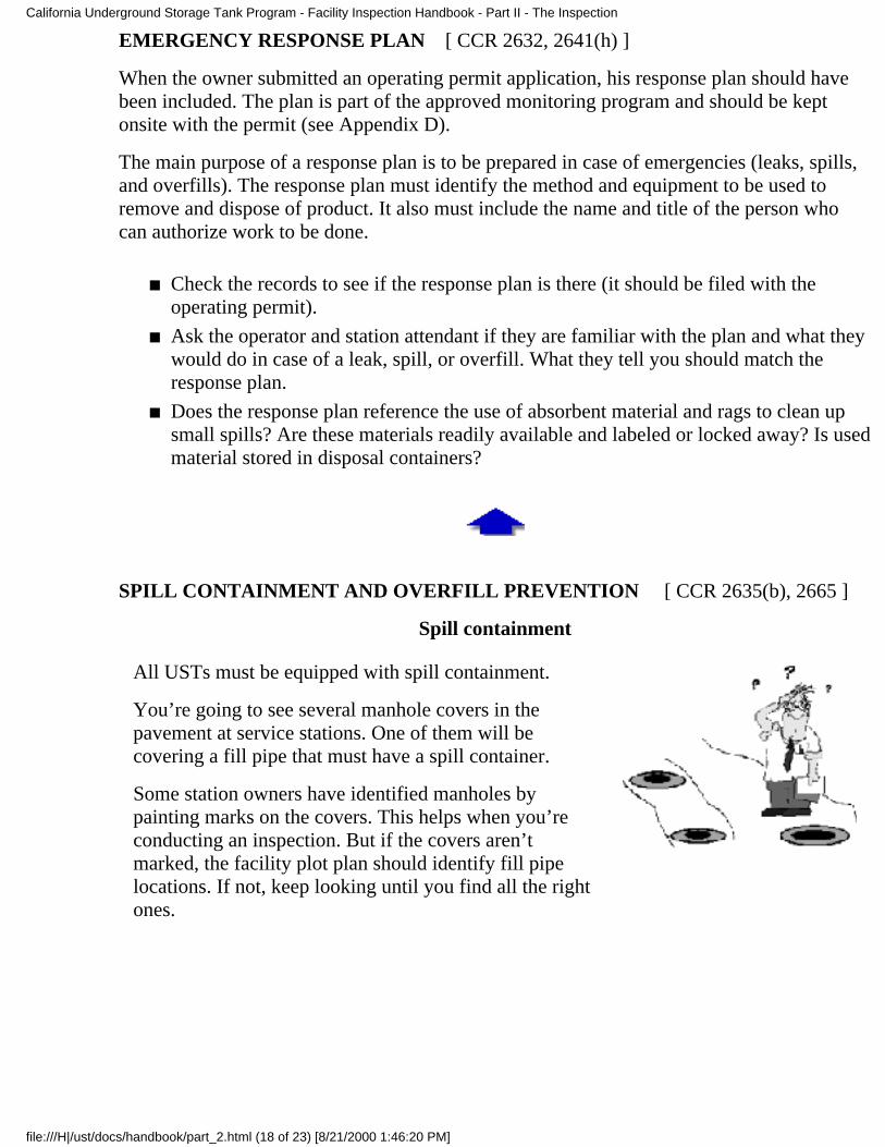
All USTs must be equipped with spill containment.
You’re going to see several manhole covers in thepavement at service stations. One of them will becovering a fill pipe that must have a spill container.
Some station owners have identified manholes bypainting marks on the covers. This helps when you’reconducting an inspection. But if the covers aren’tmarked, the facility plot plan should identify fill pipelocations. If not, keep looking until you find all the rightones.
California Underground Storage Tank Program - Facility Inspection Handbook - Part II - The Inspection
file:///H|/ust/docs/handbook/part_2.html (18 of 23) [8/21/2000 1:46:20 PM]
Once you’ve located all the fill pipes, check to seeif there is a spill container at each one. If you cansee dirt around the fill pipe there’s no spillcontainment.
■
Is the spill container empty or does it have water,product, or debris in it? The spill container will notbe effective if it’s allowed to sit there full.
■
You may see fuel around the fill pipe if the persondelivering the product has been sloppy. Withoutspill or overfill protection, a significant amount offuel could build up around the tank. You may wantto require sampling upon installation of the overfillprevention device, or note this for future referenceon the inspection report.
■
Is the spill container capable of holding aminimum of five gallons of product?
■
Is there a drain valve in the spill container anddoes it function properly? If there’s no drain valve,there must be either a pump installed in the spillcontainer or a manual pump on site. Drain valvesshould not be left open during delivery becauseharmful vapors can be emitted.
■
Is there a drop tube? Drop tubes reduce vapors andstatic electricity and help keep dipsticks verticalfor accurate product measurements.
■
The California Air Resources Board and/or the local AirQuality Management district require drop tubes in tanksstoring gasoline and they allow only drop tubes that arecertified by the Air Resources Board.
The SWRCB regulations require drop tubes if the tankowner uses statistical inventory reconciliation for leakdetection.
Overfill prevention
All USTs must be equipped with an overfill prevention system.
Check to see if there’s an overfill prevention system for all the USTs. If there is not,the facility is out of compliance.
■
California Underground Storage Tank Program - Facility Inspection Handbook - Part II - The Inspection
file:///H|/ust/docs/handbook/part_2.html (19 of 23) [8/21/2000 1:46:20 PM]
There are three types of overfill prevention:
Audible and visible alarm
High level alarms are typically connected to the automatic tank gauge and are set to alert theoperator by triggering an audible and visual alarm.
Check to see if the alarm is where the delivery driver and operator can see and hear it.■
Ball float valve or float vent valve
Usually, you’ll know if the system has a ball float valve because there will be an extractorfitting inside an access port in the ground. A ball float valve will restrict the flow of productinto the tank.
Look for it opposite the fill pipe.■
Ball float valves should not be used on suction piping systems, pressurized deliveries, loosefill connectors and spill containers in drain valves, or coaxial Stage I vapor recovery.
Automatic shut-off deviceLook down the fill pipe with your (explosion-proof) flashlight. You should be able tosee a small restriction in the fill pipe. If you don’t see the restriction, there is probablyno automatic shut-off device.
■
See LG 150, Ball Float Vent Valve vs. Fill Tube Positive Shutoff Valve, for moreinformation on overfill prevention.
Secondary containment for fill risers is not needed ifthere is an automatic shut off device installed or thecombination of a ball float valve (restricting the flow)and audible and visible alarm is used in accordance withSection 2635(b). Currently, there is no device orcombination of devices that will exempt waste oil tankrisers from secondary containment.
■
SPILL/LEAK REPORTS [ CCR 2651, 2652 ]
If the facility has had any reportable unauthorized releases, the information should be inyour files. And because you reviewed the file before the inspection, you know whether youwere given accurate information by comparing what you have in file to what the facilityfiles show.
Released product that stays inside the secondary containment (sumps and spill containers)and is removed within 8 hours must be recorded, but it does not have to be reported.However, other releases at dispensers, turbines, and fill pipes must be reported and
California Underground Storage Tank Program - Facility Inspection Handbook - Part II - The Inspection
file:///H|/ust/docs/handbook/part_2.html (20 of 23) [8/21/2000 1:46:20 PM]
investigated immediately - especially if the release reaches the environment. Dirty soil orsmells at turbine heads, leaking dispensers, or standing liquid in spill containers and sumpsoften indicate reportable releases.
Do the files contain reports of spills?■
If there was a spill, what caused it? What action did the operator take?■
If absorbent material was used, how was it disposed of?■
Were any repairs required?■
TANK AND PIPING INTEGRITY TESTS
The time to review tank test reports is when you receivethem. This has two advantages: 1) If the report indicates afailed test, you can make sure proper follow-up action istaken immediately; 2) If the test report is deficient, or thetest was not properly conducted, you can require a retest.If you are not checking tank test reports as you receivethem from tank owners, it is important to spend time onthem during your inspection.
Tank owners are required to give you 48-hours advancenotice before having their tanks tested unless you havewaived this notification requirement. You may want totake advantage of this 48-hour notice to be present for thetank test. Owners are required to submit their test resultsto your agency within 30 days.
Items to check for in a tank and piping test report (havingLGs 105 and 113 with you would come in handy here):
Check to see if the tester has a current license (LG105).
■
Check for the tester’s signature and license numberon the report.
■
Is the type of test equipment used listed in thereport?
■
Is the tester certified by the manufacturer to use theequipment (LG 105)?
■
Is the calculated leak rate less than the testingequipment’s leak threshold (LG 113)? (If thecalculated leak rate exceeds the threshold, the testresult is “fail.”)
■
California Underground Storage Tank Program - Facility Inspection Handbook - Part II - The Inspection
file:///H|/ust/docs/handbook/part_2.html (21 of 23) [8/21/2000 1:46:20 PM]
Did the tank tester wait the appropriate amount oftime to begin the test after fuel delivery/dispensing?
■
Was the test run for the right length of time and didthe tester take the proper number of readings?
■
Was there any dispensing during the test?■
FOR THE TANK TEST PART OF THE REPORT:Was the size of the tank consistent with the specifications for the test equipment (LG113)?
■
Were the tanks manifolded? If yes, were the tanks isolated for the test or were theytested together?
■
Was the in-tank water measured and reported at the beginning and end of the test?■
Did the tester determine and record depth to water table in the tank backfill?■
Did the tester compensate for the presence of water in the backfill (LG 113)?■
Was the product level in the tank during the test consistent with LG 113?■
Was the proper amount of pressure or vacuum applied to the tank (applies tononvolumetric and ullage tests)?
■
FOR THE PIPING TEST PART OF THE REPORT:Does the report specify the type of piping (suction, pressurized, or gravity flow)?■
Was the piping pressurized for the test? What was the pressure?■
Was the mechanical line leak detector removed to perform the test?■
Was the piping volume consistent with the specifications for the test?■
THIRD-PARTY EVALUATIONS [ CCR 2712(b), 2643(f) ]
The regulations refer to third-party evaluations as “performance claims” and ”performancestandards.”
Check to see that third-party evaluations for any monitoring equipment (includinginterstitial monitoring equipment and piping test equipment) are in file. They must bekept for 5 years.
■
Check to see that the equipment used is proper for the operating conditions of thefacility and the size of the tank.
■
California Underground Storage Tank Program - Facility Inspection Handbook - Part II - The Inspection
file:///H|/ust/docs/handbook/part_2.html (22 of 23) [8/21/2000 1:46:20 PM]
Any equipment or method that has been third-party certified and reviewed for compliancewith EPA’s requirements is listed in LG 113.
VAPOR OR VADOSE ZONEMONITORING WELLS
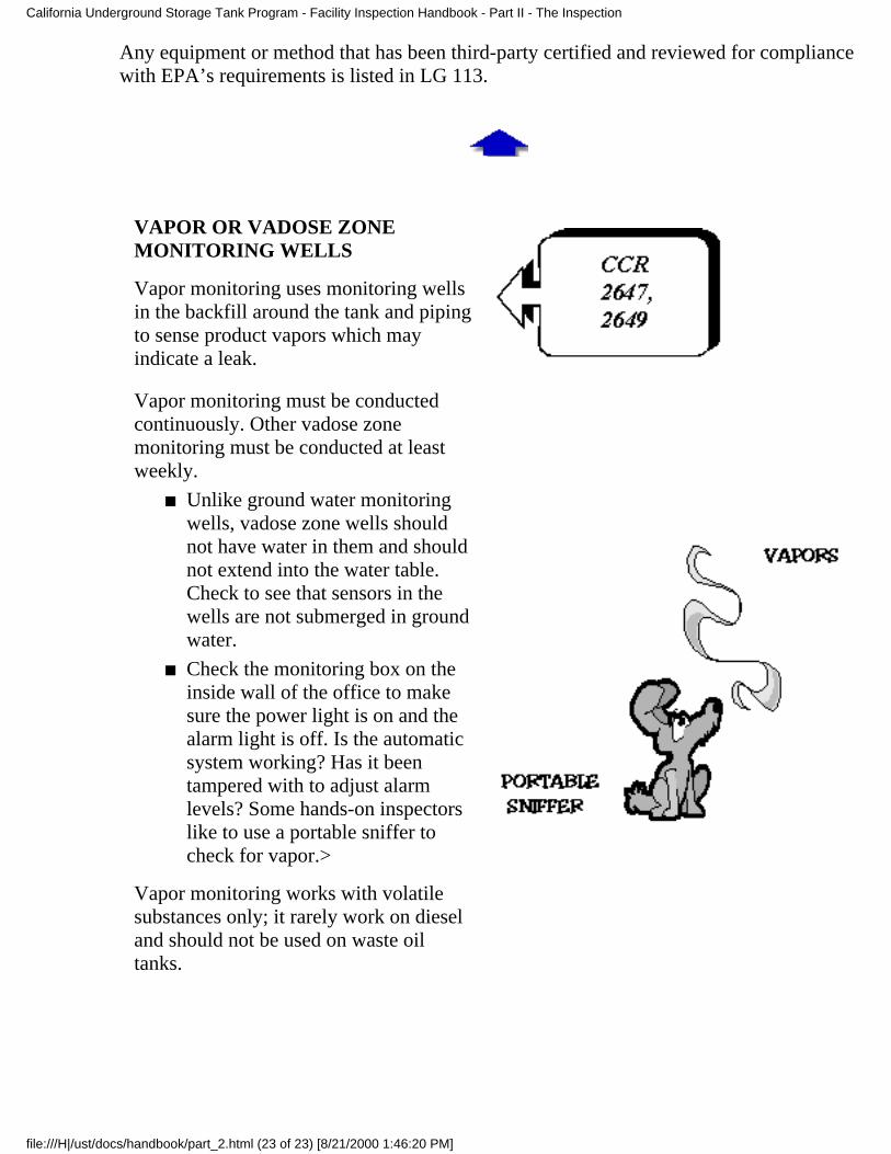
Vapor monitoring uses monitoring wellsin the backfill around the tank and pipingto sense product vapors which mayindicate a leak.
Vapor monitoring must be conductedcontinuously. Other vadose zonemonitoring must be conducted at leastweekly.
Unlike ground water monitoringwells, vadose zone wells shouldnot have water in them and shouldnot extend into the water table.Check to see that sensors in thewells are not submerged in groundwater.
■
Check the monitoring box on theinside wall of the office to makesure the power light is on and thealarm light is off. Is the automaticsystem working? Has it beentampered with to adjust alarmlevels? Some hands-on inspectorslike to use a portable sniffer tocheck for vapor.>
■
Vapor monitoring works with volatilesubstances only; it rarely work on dieseland should not be used on waste oiltanks.
California Underground Storage Tank Program - Facility Inspection Handbook - Part II - The Inspection
file:///H|/ust/docs/handbook/part_2.html (23 of 23) [8/21/2000 1:46:20 PM]