Calibration of Robot Tool Centre Point using Camera … · Calibration of Robot Tool Centre Point...
12
SERBIAN JOURNAL OF ELECTRICAL ENGINEERING Vol. 13, No. 1, February 2016, 9-20 9 Calibration of Robot Tool Centre Point using Camera-based System Zaviša Gordić 1 , Claudio Ongaro 2 Abstract: Robot Tool Centre Point (TCP) calibration problem is of great importance for a number of industrial applications, and it is well known both in theory and in practice. Although various techniques have been proposed for solving this problem, they mostly require tool jogging or long processing time, both of which affect process performance by extending cycle time. This paper presents an innovative way of TCP calibration using a set of two cameras. The robot tool is placed in an area where images in two orthogonal planes are acquired using cameras. Using robust pattern recognition, even deformed tool can be identified on images, and information about its current position and orientation forwarded to control unit for calibration. Compared to other techniques, test results show significant reduction in procedure complexity and calibration time. These improvements enable more frequent TCP checking and recalibration during production, thus improving the product quality. Keywords: Robot TCP calibration, Camera system, Smart factories. 1 Introduction Factories of today have made a big leap forward from factories a couple of decades ago. The role of human on hazardous, repetitive, or tedious tasks has been assigned to automated machines. Out of all machines on production and assembly lines, industrial robots offer greatest flexibility and adaptability. In order to improve working condition, efficiency, and quality of products, machines and robots will have to form an integrated and interconnected entity which will become increasingly independent from human intervention, slowly becoming Factories of the Future. It is not hard to imagine that many of those factories will utilize robots on various tasks, and a lot of research and development nowadays is going towards improving their performance, control algorithms, and design. Making robots more aware of their surroundings is one of the crucial things in automated production, and one of essential steps in that direction is giving them the information about the tool they work with. 1 ETF Robotics Laboratory, School of Electrical Engineering, University of Belgrade, Bulevar kralja Aleksandra 73, 11020 Belgrade, Serbia; E-mail: [email protected] 2 Advanced Automation Technologies srl, Via Martiri delle Foibe, 12, Conegliano TV, Italia; E-mail: [email protected] UDC: 004.896 DOI: 10.2298/SJEE1601009G
Transcript of Calibration of Robot Tool Centre Point using Camera … · Calibration of Robot Tool Centre Point...

SERBIAN JOURNAL OF ELECTRICAL ENGINEERING Vol. 13, No. 1, February 2016, 9-20
9
Calibration of Robot Tool Centre Point using Camera-based System
Zaviša Gordić1, Claudio Ongaro2
Abstract: Robot Tool Centre Point (TCP) calibration problem is of great importance for a number of industrial applications, and it is well known both in theory and in practice. Although various techniques have been proposed for solving this problem, they mostly require tool jogging or long processing time, both of which affect process performance by extending cycle time. This paper presents an innovative way of TCP calibration using a set of two cameras. The robot tool is placed in an area where images in two orthogonal planes are acquired using cameras. Using robust pattern recognition, even deformed tool can be identified on images, and information about its current position and orientation forwarded to control unit for calibration. Compared to other techniques, test results show significant reduction in procedure complexity and calibration time. These improvements enable more frequent TCP checking and recalibration during production, thus improving the product quality.
Keywords: Robot TCP calibration, Camera system, Smart factories.
1 Introduction
Factories of today have made a big leap forward from factories a couple of decades ago. The role of human on hazardous, repetitive, or tedious tasks has been assigned to automated machines. Out of all machines on production and assembly lines, industrial robots offer greatest flexibility and adaptability. In order to improve working condition, efficiency, and quality of products, machines and robots will have to form an integrated and interconnected entity which will become increasingly independent from human intervention, slowly becoming Factories of the Future. It is not hard to imagine that many of those factories will utilize robots on various tasks, and a lot of research and development nowadays is going towards improving their performance, control algorithms, and design. Making robots more aware of their surroundings is one of the crucial things in automated production, and one of essential steps in that direction is giving them the information about the tool they work with.
1ETF Robotics Laboratory, School of Electrical Engineering, University of Belgrade, Bulevar kralja Aleksandra 73, 11020 Belgrade, Serbia; E-mail: [email protected]
2Advanced Automation Technologies srl, Via Martiri delle Foibe, 12, Conegliano TV, Italia; E-mail: [email protected]
UDC: 004.896 DOI: 10.2298/SJEE1601009G

Z. Gordić, C. Ongaro
10
Robot Tool Centre Point (TCP) calibration presents an ordinary task which needs to be carried out in order to enable robot to perform any reasonable action with the tool. Although repeatability of modern robotic manipulators is satisfying, they still need an information about the TCP in relation to their coordinate system. Besides manual method, robots can be calibrated in automated ways.
Model-based calibration methods require four steps [1]. First, modeling the mechanism of the robot, followed by measuring some specific TCP positions. After that, it is needed to identify the true robot frame parameters, and then to compensate existing TCP positions. However, there are methods that do not exclusively rely on robot models.
One of automated solutions is offered by ABB in form of BullsEye system [2]. Calibration unit resembles an arc with light beam generator and detector on its opposing ends. During calibration process, robot moves the tool inside the calibration unit intersecting the light beam from different directions. Using this principle, 3 dimension TCP calibration can be performed.
Further improvement in performance, but using same principle was done by LEONI. Their advintec TCP-3D/5D unit is capable of up to 5-dimension TCP calibration. It uses two mutually perpendicular infrared beams, enabling it to increase number of dimensions it can calibrate, or decreasing the time and number of steps needed to perform calibration. Nevertheless, it still requires several steps to perform all the measurements, which increases calibration time.
One computer vision solution is presented in [3]. It uses an USB camera connected to a computer in order to acquire needed images. From those images, algorithms can perform a 6-dimension TCP calibration. In order to increase accuracy of this method, an iterative procedure was proposed by the author. While this approach offers a simple and affordable camera-based solution, it does not eliminate the effect of external influences, like lighting conditions or dust. Additionally, the algorithm looks for distinct points on the object, and can be confused when working with rotation symmetric tools.
The objective of this paper is to demonstrate an innovative camera-based calibration solution. Small area footprint and robust design of the calibration unit, explained in Section 2, enable easy installation in industrial environment and prove that it is practically orientated.
The main idea behind this calibration approach is to simultaneously acquire images of the tool from two orthogonal planes, and use them to determine tool's orientation and TCP position. Robot needs to introduce the tool into the image acquisition area of the calibration unit, after which it will receive feedback in form of angular offsets in two planes from the reference tool orientation. After correcting angular offsets, the robot will receive information about TCP position offsets in x, y and z axis from the reference point in image acquisition

Calibration of Robot Tool Centre Point using Camera-based System
11
area. The principle behind this approach is explained in Section 3 in more details.
Section 4 shows main observations based on initial test results. Data shows successful angle and position measurements, and prove that the calibration principle can perform well with selected optics and hardware. However, it is noted that the best performance is achieved when the robot tool is positioned closer to the centre of the image, where camera distortion is least prominent.
In Section 5, it is concluded that presented principle offers a simple and reliable solution for up to 5-dimension TCP calibration. It also provides great flexibility and significantly reduces calibration and overall cycle time. This enables more frequent recalibration checks, which leads to higher quality of product. It is also mentioned that the design might have potential application in Factories of the Future. Conclusion also offers directions for further development and improvements.
2 Calibration Unit Design
In order to make the calibration unit suitable for industrial use, all the necessary components are packed into a single unit. At the top of the unit an image acquisition area is located, in a form of a box with open top from where the robot can introduce the tool. Two neighboring vertical sides of the box are used as background panels and remaining two sides are transparent to enable image acquisition, as shown on Fig. 1.
Fig. 1 – Image acquisition area with mirrors, background panels and LED strips.
Background panels are illuminated with LED strips which can be triggered by camera. On the transparent sides of the acquisition area, two mirrors, placed at 45 degrees were introduced into system to reflect the image vertically downwards. As shown on Fig. 2, cameras are positioned pointing upwards towards mirrors, close to the bottom end of corresponding vertical sides of calibration unit. By choosing this layout, small area footprint of the calibration
Z. Gordić, C. Ongaro
12
unit was kept, while increasing the distance between cameras and the observed object, thus decreasing image distortion imposed by camera's lens. Mirrors are placed in sealed chambers to prevent contamination by dust or humidity. The camera used in the prototype is Basler acA2040-90uc USB 3.0 camera with the CMOSIS CMV4000 CMOS sensor. It is capable of delivering 90 frames per second at 4 MP resolution.
Power supply, fanless PC, cables and connectors are all located inside the calibration unit casing. Cover can be removed from one corner of the casing to enable easy access to internal components. The information about calibration unit is given in Table 1.
Fig. 2 – Overall layout of the calibration unit with access cover removed.
Table 1 Calibration unit information.
Camera type Basler acA2040-90uc
Distance of camera from the acquisition area 353 mm
External dimension of the unit (l × w × h) 300 mm × 300 mm × 635 mm
Dimension of image acquisition area (l × w × h) 95 mm × 95 mm × 80 mm
Calibration of Robot Tool Centre Point using Camera-based System
13
3 Calibration Principle
Calibration of robot TCP means providing the robot with information about position and orientation of TCP in robot's coordinate system. Usually, it is required that provided information is relative to the robot's flange. Coordinates of flange are available at any moment from the robot's side, so what is really needed is only information about the position and orientation of the tool.
The main working principle for this calibration approach is based on acquiring images of the robot tool from two orthogonal planes. With properly illuminated background, a dark contour of the tool can be recognized by the pattern recognizing algorithm. From that point on, the calibration algorithm has two steps. First, the angle between the current longitudinal axis of the tool and previously referenced axis is measured on each image, and forwarded to the control unit. If the current angle measurement is not satisfactory, robot can use provided information to make corrections in angle in order to match desired orientation. Second step is to measure the coordinates of the TCP on both image planes. Measured position in then compared with position of one point in space of image acquisition area, which represents desired position for the TCP. The offset between those two points is sent to the robot's control unit, in order to move the tool into desired position. Once the robot has guided the tool to match desired position and orientation, it remembers the position of its flange. Since coordinates of desired position in camera acquisition area are known, as well as coordinates of flange, parameters of the tool can easily be calculated and sent to the robot. The following text will provide the more detailed elaboration of the processes in described procedure.
The problem of identifying the tool and measuring the angle and position on the image is assigned to National Instruments' Image processing software, and it is not the subject of this paper.
First issue needed to overcome is related with determining the angles of rotation. After the images have been acquired, and angles on both images have been measured, it is needed to determine the angles at which the tool must be rotated to reach desired orientation. Namely, out of two measured angles, only one can be considered to be actual angle, in which case the second angle is the consequence of perspective distortion. If the goal is to lead the robot tool into desired angular position using two sequential rotations in corresponding image planes, than it is of crucial importance to determine the exact value of both angles, excluding the perspective distortion.
Perspective distortion of one angle value is a result of the fact that one of the rotations is not in plane that is parallel to the corresponding image plane. Let us consider that the measured angular position of the tool is a result of two sequential rotations in mutually orthogonal planes.
Z. Gordić, C. Ongaro
14
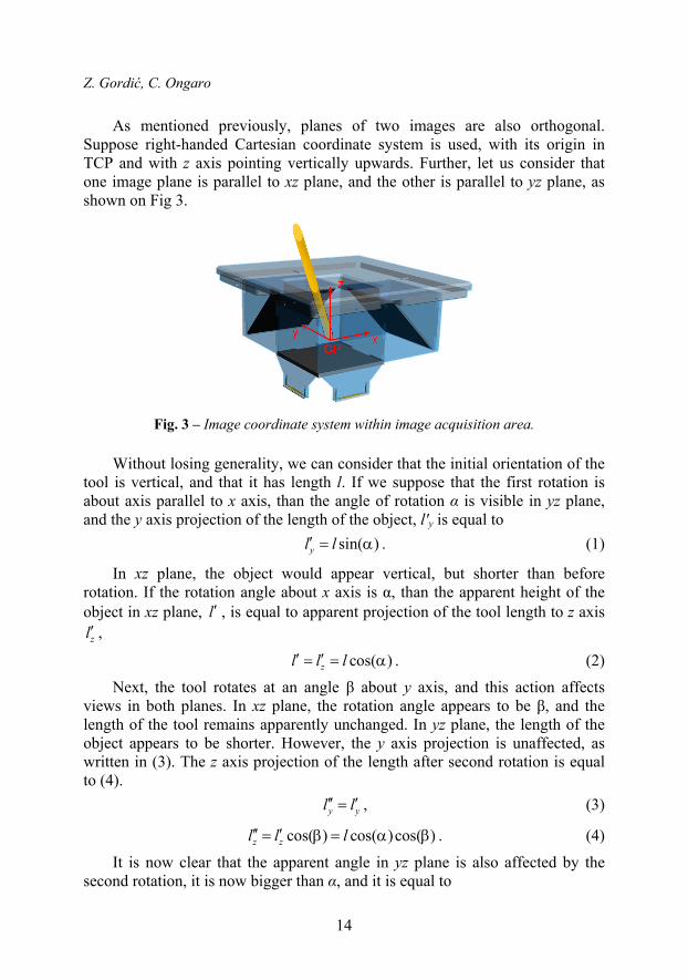
As mentioned previously, planes of two images are also orthogonal. Suppose right-handed Cartesian coordinate system is used, with its origin in TCP and with z axis pointing vertically upwards. Further, let us consider that one image plane is parallel to xz plane, and the other is parallel to yz plane, as shown on Fig 3.
Fig. 3 – Image coordinate system within image acquisition area.
Without losing generality, we can consider that the initial orientation of the tool is vertical, and that it has length l. If we suppose that the first rotation is about axis parallel to x axis, than the angle of rotation α is visible in yz plane, and the y axis projection of the length of the object, l′y is equal to
sin( )yl l . (1)
In xz plane, the object would appear vertical, but shorter than before rotation. If the rotation angle about x axis is α, than the apparent height of the object in xz plane, l , is equal to apparent projection of the tool length to z axis
zl ,
cos( )zl l l . (2)
Next, the tool rotates at an angle β about y axis, and this action affects views in both planes. In xz plane, the rotation angle appears to be β, and the length of the tool remains apparently unchanged. In yz plane, the length of the object appears to be shorter. However, the y axis projection is unaffected, as written in (3). The z axis projection of the length after second rotation is equal to (4).
y yl l , (3)
cos( ) cos( )cos( )z zl l l . (4)
It is now clear that the apparent angle in yz plane is also affected by the second rotation, it is now bigger than α, and it is equal to
Calibration of Robot Tool Centre Point using Camera-based System
15
sin( )
arctan arctancos( )cos( )
y
z
l
l
. (5)
Angles that would be seen by the pattern recognition algorithm are in yz plane and β in xz plane. The angle of second rotation remained unaffected by the perspective distortion. In an analogous way, it can be proved that if the rotations happened in different order, the angle α would stay unaffected, and the angle would be
sin( )
arctancos( )cos( )
. (6)
Having shown that the angles seen on image are not the real angles of rotation, but result of perspective distortion, it is now necessary to find a way of calculating real angles. In reality, the algorithm would not know which rotation happened first. Therefore, for every pair ( meas meas, ) of measured angles in xz
and yz plane respectively, two pairs of real angles exist, marked as ( meas , )
and ( meas, ).
According to (5), if the first rotation happened about x axis, the real angle α is not visible, but it can be calculated using (7).
arctan tan( )cos( ) . (7)
In similar way, formula for calculating angle can be derived from (6).
Having determined the real angle of the rotation, it is possible to position the tool vertically. Also, it is clear that by rotating the tool for the opposite angles, it can be brought to the initial position from vertical position. The situation where desired tool orientation is not vertical can be solved in different ways. One of the trivial solutions is to first measure the angles in desired position and calculate real angles of rotation. In that way, it is known how to move the tool from desired position to the vertical position, and vice versa. Then, for any other measured position, tool can be first brought to vertical position, and from that position rotated for the angles that bring it to desired position.
The process described above represents the first step of calibration procedure. Having orientated the object correctly, it is important to measure the translation offset of the TCP from the desired position of TCP. This operation is first done by measuring and remembering the desired TCP coordinates on both images, and then comparing it to the TCP position of the tool in every calibration check. If the measured TCP position does not match the desired position, robot can correct it using information provided by the calibration unit. Then, the robot receives TCP parameters calculated by the calibration unit

Z. Gordić, C. Ongaro
16
based on flange coordinates when TCP is in desired point, and previously known position of that desired point.
Theoretically, the calibration procedure can be performed without the movement which compensates the position. The solution would be to use offset information and flange coordinates in order to calculate what would be the flange coordinates in when TCP is in desired position. However, this action is not recommended because the accuracy of offset measurement cannot be guaranteed in every point of image acquisition space due to image distortion.
Because of camera distortion, formula given with (7) is absolutely applicable in situations where cameras with telecentric lenses are used. However, the size of telecentric lenses that can cover the needed field of view and their price are far too big to be practically useable in industrial applications. For example, the length of telecentric optics which have field of vision of 62 mm in diameter is more than 540 mm in length, which combined with other components would give total height of the calibration unit of more than one meter.
When using regular lenses, effects of camera distortion become less prominent as the distance from the observed object and camera increases, and theoretically decrease to zero as the distance increases to infinity. In order to increase the distance of the camera from the tool, cameras are positioned in the way explained previously within calibration unit design section. The described solution is a result of the trade-off between calibration unit dimensions and desirable distance.
4 Main Results and Discussion
Testing consisted of two phases. In first phase, image acquisition and pattern recognition algorithm were tested separately. Calibration unit was tested to check if the images are acquired with good quality and reliability, Special attention was dedicated to external influences analysis, which proved to be not significant.
Pattern recognition algorithm and (7) were first tested with images generated using a 3D modeling and rendering software. The advantage of these images is that the virtual tool can be rotated at any known angle, so the (7) can be tested to full extent. These tests also showed that the pattern recognition works accurately, and reliably. Angles obtained from the algorithm were measured with high accuracy and repeatability. Calculations of distorted angle matched those of the real rotation with similar accuracy.
Second phase was dedicated to testing the whole system, with real test objects and real environmental influences. Based on initial tests, it was concluded that the distortion effect is not significantly prominent and that (7) can be used with good results.
Calibration of Robot Tool Centre Point using Camera-based System
17
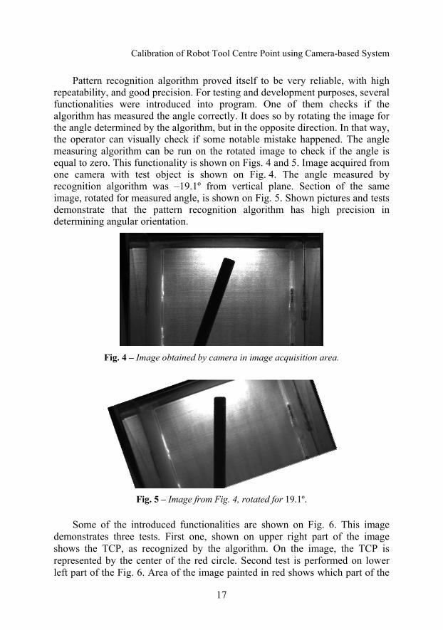
Pattern recognition algorithm proved itself to be very reliable, with high repeatability, and good precision. For testing and development purposes, several functionalities were introduced into program. One of them checks if the algorithm has measured the angle correctly. It does so by rotating the image for the angle determined by the algorithm, but in the opposite direction. In that way, the operator can visually check if some notable mistake happened. The angle measuring algorithm can be run on the rotated image to check if the angle is equal to zero. This functionality is shown on Figs. 4 and 5. Image acquired from one camera with test object is shown on Fig. 4. The angle measured by recognition algorithm was –19.1º from vertical plane. Section of the same image, rotated for measured angle, is shown on Fig. 5. Shown pictures and tests demonstrate that the pattern recognition algorithm has high precision in determining angular orientation.
Fig. 4 – Image obtained by camera in image acquisition area.
Fig. 5 – Image from Fig. 4, rotated for 19.1º.
Some of the introduced functionalities are shown on Fig. 6. This image demonstrates three tests. First one, shown on upper right part of the image shows the TCP, as recognized by the algorithm. On the image, the TCP is represented by the center of the red circle. Second test is performed on lower left part of the Fig. 6. Area of the image painted in red shows which part of the

Z. Gordić, C. Ongaro
18
image is recognized as part of the tool. The third check is visible on both upper and lower part of the Fig. 6 in form of a straight blue line. The line goes through the center of the tool, as determined by the algorithm.
Fig. 6 – Images used for algorithm verification.
These tests were performed on a number of test objects. Some of test objects were designed especially for testing purpose, such as one shown on Figs. 4 and 5, while some of them are every-day objects, such as screw shown on Fig. 6. All objects were held in place by a specially designed plate with drilled holes through which the test objects can be inserted into image acquisition area. The plate can be rotated to check if the algorithm measures angles symmetrically, and do both cameras see the same angle. For example, the angle measured on Fig. 4 was 70.9º from the horizontal plane, while the angle on Fig. 6 was 109.1º, which means that both of them are 19.1º in absolute value from the vertical plane. This demonstrates that the algorithm does not favour different areas of the image, and that the camera is positioned correctly, i.e. the camera does not introduce any angular error. Tests for camera in different plane were done with similar conclusion.
One of the testing phases also included testing of TCP identification in situations where it is not clearly visible. It can happen that, due to unfavourable orientation of the tool, the real TCP is not visible for the algorithm, as it is shown on Fig. 7 on example A. Therefore, it must be estimated. At this moment, such functionality of pattern recognition algorithm is not developed.

Calibration of Robot Tool Centre Point using Camera-based System
19
However, the longitudinal axis of the object can be recognized, and therefore tool can be oriented in a favourable way, in which the TCP can be properly identified.
During testing, it was noticed that the distortion is less prominent in the areas closer to the centre of the image. Also, it was noted that the angular measuring precision is greater if the tool is closer to vertical position. Therefore, in order to have optimal conditions regarding accuracy, it is recommended to set desired orientation to vertical, and desired TCP position in the centre of images, as it is shown on Fig. 7 on example B.
Pattern recognition was tested for robustness by deliberately damaging the shape of the images. This checks how the algorithm would behave in situations where tool is deformed, or the lighting conditions on image are not optimal. One other thing that was recognized as a potential source for errors were scratches, dirt specs, and other types of visual contaminations on transparent sides, or on background panels in the image acquisitions box. All listed disturbances were not able to introduce any significant error, thanks to the fact that the pattern recognition algorithm observes whole object, rather than only one section of it. This presents an important advantage compared to the methods where moving tool intersects light beams.
Fig. 7 – Test object: A - unfavourable orientation; B - favourable orientation.
5 Conclusion
The TCP calibration approach presented in this paper offers an innovative solution to well known industrial problem. It was shown that the principle can be used to successfully determine up to 5-dimension tool position. Relations between viewed and real angular orientation were derived, commented and tested. Mathematical relations solved the problem of perspective, while the calibration unit design reduced the influence of camera distortion. Calibration

Z. Gordić, C. Ongaro
20
procedure is greatly simplified and its duration is significantly reduced. Pattern recognition algorithm proved itself precise, reliable and robust, even when working with different shapes and deformed tools.
Calibration procedure and the system itself are designed to be fully automatic, making it ideal for automated facilities where presence of human is rarely required, after the installation of the system. The system can provide great flexibility not only when automatically changing tools in order to perform different operations, but also when introducing new tool. Maintenance is reduced to minimum, and it has potential to be fully integrated and shared between multiple robots and other machines in Factories of the Future. Theoretically speaking, there is no limit to the number of robots that could use one calibration unit, as long as it is in their working range.
Further work might also tackle design of a new pattern recognition algorithm which would be able to estimate the TCP even on images where it is not directly visible due to unfavourable orientation of the tool. Use of different background illuminators and appropriate camera filters can be implemented in order to reduce the influence of interference on neighbouring images.
7 Acknowledgment
During work on this paper, tests were made on calibration unit designed and built by ADAT srl. The solution is patent pending N.: TV2014A000165, as listed in [4].
6 References
[1] F.S. Cheng: Calibration of Robot Reference Frames for Enhanced Robot Positioning Accuracy (In Robot Manipulators), INTECH, Rijeka, Croatia, 2008.
[2] BullsEye Application Manual, Revision G. ABB Robotics, Vasteras, Sweden, 2012.
[3] J. Hallenberg: Robot Tool Center Point Calibration using Computer Vision, MSc Thesis, Linkoping University, Linkoping., Sweden, 2007.
[4] C. Ongaro: Device and Method for Calibrating of Torch Welding Robot, Pending Patent No. TV2014A000165, Nov. 2014. (In Italian).