Calibration of a Reusable Nonlinear Beam-Column Connection ...
12
Calibration of a Reusable Nonlinear Beam-Column Connection for Use in an Experimental Ground Motion Scaling Study A.P. O’Donnell, 1 Y.C. Kurama, 1 E. Kalkan, 2 A.A. Taflanidis 1 1 Civil Engin. and Geological Sci., Univ. of Notre Dame, 156 Fitzpatrick Hall, Notre Dame, IN 46556; E-mail: [email protected], [email protected], [email protected] 2 Earthquake Science Center, United States Geological Survey, 345 Middlefield Rd., Menlo Park, CA 94025; E-mail: [email protected] ABSTRACT Ground motion selection and scaling comprises one of the most important components of any seismic risk assessment study that involves response history analysis. The related research to date has been based on analytical studies of mostly single-degree-of-freedom systems, with fewer studies conducted using multi-degree- of-freedom systems. By contrast, the research effort described in this paper focuses on an experimental evaluation based on shake table tests of a small-scale six-story building frame specimen utilizing a calibrated, reusable, rotational, nonlinear beam- column connection. The paper focuses on the development and calibration of this connection and an associated analytical simulation to quantify the uncertainty introduced into the shake table results due to the variability in the calibrated strength of the connection. It is shown that the six-story frame structure outfitted with nonlinear connections at each beam end is effective in filtering the variability in the local connection behavior such that the uncertainty in the global response of the structure is often less than that of the connection. Ultimately, these results will be used in conjunction with the shake table test data from the six-story frame structure for the development of guidelines and procedures to achieve reliable demand estimates from nonlinear response history analysis in seismic design. INTRODUCTION Nonlinear response history analysis (RHA) is a powerful method for the performance- based seismic design and evaluation of building structures (e.g., for tall or irregular structures, structures with innovative structural systems and materials, and/or structures on soft soil). An important task in this rigorous analysis method is the selection and scaling of an appropriate suite of ground motion records for the site-specific hazard level(s) considered in the design [e.g., Maximum Considered Earthquake (MCE) level, Design Basis Earthquake (DBE) level]. With the availability of modern structural analysis packages and tools, the ground motion record itself has become the most important factor governing the outcome and amount of uncertainty from nonlinear RHA results. The input ground motion is also the single parameter with the least guidance provided in current building codes and provisions, resulting in the use of mostly subjective choices in the selection and scaling of ground motions for nonlinear RHA. Most of the research to date on ground motion scaling has been on single- degree-of-freedom systems (e.g., Baez and Miranda 2000; Chopra and Chinatanapakdee 2004; Luco and Cornell 2007; Martinez-Rueda 1998; Miranda
Transcript of Calibration of a Reusable Nonlinear Beam-Column Connection ...

Calibration of a Reusable Nonlinear Beam-Column Connection for Use in an Experimental Ground Motion Scaling Study
A.P. O’Donnell,1 Y.C. Kurama,1 E. Kalkan,2 A.A. Taflanidis1
1Civil Engin. and Geological Sci., Univ. of Notre Dame, 156 Fitzpatrick Hall, Notre Dame, IN 46556; E-mail: [email protected], [email protected], [email protected] 2Earthquake Science Center, United States Geological Survey, 345 Middlefield Rd., Menlo Park, CA 94025; E-mail: [email protected] ABSTRACT Ground motion selection and scaling comprises one of the most important components of any seismic risk assessment study that involves response history analysis. The related research to date has been based on analytical studies of mostly single-degree-of-freedom systems, with fewer studies conducted using multi-degree-of-freedom systems. By contrast, the research effort described in this paper focuses on an experimental evaluation based on shake table tests of a small-scale six-story building frame specimen utilizing a calibrated, reusable, rotational, nonlinear beam-column connection. The paper focuses on the development and calibration of this connection and an associated analytical simulation to quantify the uncertainty introduced into the shake table results due to the variability in the calibrated strength of the connection. It is shown that the six-story frame structure outfitted with nonlinear connections at each beam end is effective in filtering the variability in the local connection behavior such that the uncertainty in the global response of the structure is often less than that of the connection. Ultimately, these results will be used in conjunction with the shake table test data from the six-story frame structure for the development of guidelines and procedures to achieve reliable demand estimates from nonlinear response history analysis in seismic design. INTRODUCTION Nonlinear response history analysis (RHA) is a powerful method for the performance-based seismic design and evaluation of building structures (e.g., for tall or irregular structures, structures with innovative structural systems and materials, and/or structures on soft soil). An important task in this rigorous analysis method is the selection and scaling of an appropriate suite of ground motion records for the site-specific hazard level(s) considered in the design [e.g., Maximum Considered Earthquake (MCE) level, Design Basis Earthquake (DBE) level]. With the availability of modern structural analysis packages and tools, the ground motion record itself has become the most important factor governing the outcome and amount of uncertainty from nonlinear RHA results. The input ground motion is also the single parameter with the least guidance provided in current building codes and provisions, resulting in the use of mostly subjective choices in the selection and scaling of ground motions for nonlinear RHA.
Most of the research to date on ground motion scaling has been on single-degree-of-freedom systems (e.g., Baez and Miranda 2000; Chopra and Chinatanapakdee 2004; Luco and Cornell 2007; Martinez-Rueda 1998; Miranda
1993; Nau and Hall 1984; Vidic et al. 1994) with fewer studies on multi-degree-of-freedom systems (e.g., Kalkan and Chopra 2010, 2011; Kalkan and Kwong 2011; Alavi and Krawinkler 2000; Kurama and Farrow 2003; Shome and Cornell 1998). Furthermore, the previous research is based solely on numerical simulations, with no experimental data available for the validation of the results. Considering these issues, the research effort described in this paper is conducting a large number of small-scale shake table experiments of a re-configurable nonlinear multi-story building frame structure, depicted in Fig. 1, using an exhaustive set of ground motion records. These tests are performed in conjunction with a probabilistic analytical investigation to form a comprehensive, experimentally-validated study on dynamic response, considering a range of building periods (by changing the number of mass plates attached to the structure), lateral strengths (by changing the strength of the nonlinear beam-column connections), and ground motion records. More information on the six-story test structure as well as the ground motions suites and scaling methods investigated by the project can be found in O’Donnell et al. (2011)
Ultimately, the results from this project will be used to provide the experimental evidence needed for the evaluation of different ground motion scaling methods, including the effects of different structure characteristics on the accuracy (that is, ability to provide accurate estimates of the median seismic demands – e.g., peak roof displacement – as if a much larger set of records were used) and efficiency (that is, ability to minimize the number of records needed to reliably obtain these accurate median demand estimates) of the scaling methods. In accordance with this ultimate goal, the focus of the current paper is to discuss: 1) the design and calibration of a reusable, rotational nonlinear beam-column connection that was developed for the six-story frame specimen; and 2) an associated analytical simulation to quantify the uncertainty introduced into the shake table results due to the variability in the calibration of the beam-column connection. SIGNIFICANCE AND RELEVANCE OF RESEARCH The unique aspect of this investigation that sets it apart from previous research in the field of multi-degree-of-freedom nonlinear response history analysis and ground
(a) (b) Fig. 1. Six-story frame (nonlinear connections not shown):
(a) schematic; (b) test setup.
motion scaling is the use of a nonlinear building frame structure subjected to shake table tests. A rotational beam-column connection is developed to emulate the nonlinear behavior and energy dissipation that may be exhibited by building frame structures under earthquake loading. The connection is designed to be reusable (i.e., damage-free) allowing repeated shake table testing from essentially the same initial conditions of the frame specimen without the need to repair or replace any component of the structure under a series of ground motion records. Additionally, the connection can be calibrated to achieve different moment strengths, thus allowing structures with different lateral strengths to be investigated. Through an analytical simulation, this paper quantifies the uncertainty introduced into the shake table frame test results due to variability in the repeated use of the beam-column connection. FUNCIONALITY REQUIREMENTS FOR NONLINEAR CONNECTION The nonlinear connection was designed to emulate the behavior of a yielding beam-column joint region in a multi-story building frame structure. The connection should exhibit essentially linear-elastic behavior up to a “yield” moment, before becoming nonlinear and reaching a calibrated maximum strength. In the nonlinear range, the connection should continue to rotate in a ductile manner and dissipate energy under repeated loading cycles without undergoing strength loss. The connection should not add too much mass or stiffness to the six-story test frame (so that the building period is not affected) and be relatively easy to restore to its original condition upon undergoing nonlinear rotations during an earthquake.
Since the main overall objective of this research is to evaluate the changes in the seismic demands of a building (e.g., peak displacement demands) due to different ground motion scaling methods, the parameter of interest is the input ground motion while the building properties remain constant for each configuration. It is therefore important that the nonlinear connection exhibits consistency in its behavior so as not to introduce any significant variability into the results under repeated use. Further, the connection behavior must be predictable so that the lateral strength of the building can be reliably prescribed and a reliable analytical model of the structure can be built.
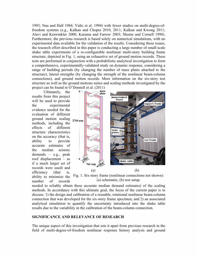
BACKGROUND FOR NONLINEAR CONNECTION DEVELOPMENT The design of the nonlinear beam-column connection was based on a rotational friction damper that was previously developed for unbonded post-tensioned precast concrete frame structures (Morgen and Kurama 2004). To supplement quasi-static precast beam-column subassembly test results, a series of isolated damper experiments were conducted under dynamic loading (Morgen and Kurama 2009) to determine the effects of loading displacement rate on the damper behavior. Frequency dependency tests, displacement amplitude dependency tests, as well as test sequences with different damper normal forces were conducted on two types of friction interfaces: (1) lead-bronze alloy against stainless steel; and (2) lead-bronze alloy against cast steel alloy. Sample results for the lead-bronze alloy against stainless steel friction interfaces can be seen in Fig. 2. The experiments showed that the dampers can provide predictable and consistent levels of strength and energy dissipation that is
largely independent of excitation displacement, frequency, and velocity for the ranges expected to occur during an earthquake. The results were used to determine the coefficient of friction, μ, for the dampers and to verify an analytical model for friction-damped precast concrete frame buildings.
Fig. 2. Characterization of lead-bronze alloy against stainless steel friction interfaces:
(a) coefficient of friction; (b) friction force versus slip displacement. NONLINEAR BEAM-COLUMN CONNECTION DESIGN General Features and Geometry. Based on the results from Morgen and Kurama (2004, 2009), a nonlinear beam-column connection utilizing sliding friction interfaces was chosen for the purposes of this research. The benefits of using friction include: (1) repeatable, damage-free behavior that is relatively independent of slip velocity and displacement amplitude; (2) close-to-rectangular force-displacement characteristics with large energy dissipation per cycle; and (3) large initial stiffness allowing slip to occur early in the response, and thus, providing energy dissipation beginning at small lateral displacements of the frame.
As shown in Fig. 3, the connection design consists of two components creating a total of 20 rotational friction interfaces. The connection component bolted to the beam end is fabricated out of stainless steel and the component bolted to the column is lead-bronze (brass) alloy. The use of lead-bronze alloy at the friction interfaces is desirable because the material “self-lubricates” when rubbing against an adjacent metal surface, which helps to reduce the phenomenon of stick-slip and results in a consistent value for the coefficient of friction that is relatively independent of velocity (a desirable characteristic for design and performance).
The moment strength of the connection is controlled by the normal force, Fn applied to the friction interfaces using a high-strength shoulder bolt. The normal force Fn generates the friction required to develop the moment resistance when the connection “teeth” are rotated with respect to one another. Belleville washers are used to maintain a consistent level of normal force during each test due to their spring-like behavior and consistency through many loading and unloading cycles.
The outside dimensions of the connection components were selected to be compatible with the 38-mm thickness and 102-mm width of the beam members of the six-story frame. A tooth thickness of 5.5-mm was used producing a connection with 21 teeth and 20 friction interfaces. This design ensured that the number of friction interfaces was adequate to achieve the desired moment strength of the connection without overstressing the shoulder bolt or washers, while allowing the teeth to
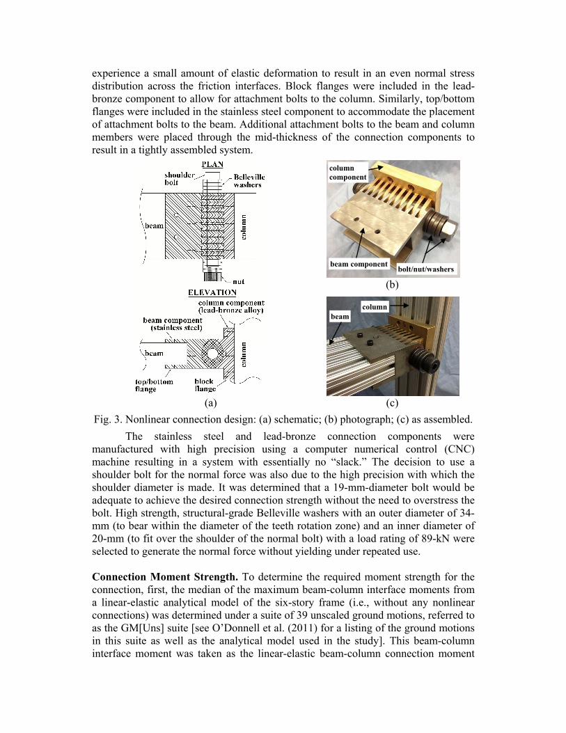
experience a small amount of elastic deformation to result in an even normal stress distribution across the friction interfaces. Block flanges were included in the lead-bronze component to allow for attachment bolts to the column. Similarly, top/bottom flanges were included in the stainless steel component to accommodate the placement of attachment bolts to the beam. Additional attachment bolts to the beam and column members were placed through the mid-thickness of the connection components to result in a tightly assembled system.
(b)
(a) (c) Fig. 3. Nonlinear connection design: (a) schematic; (b) photograph; (c) as assembled.
The stainless steel and lead-bronze connection components were manufactured with high precision using a computer numerical control (CNC) machine resulting in a system with essentially no “slack.” The decision to use a shoulder bolt for the normal force was also due to the high precision with which the shoulder diameter is made. It was determined that a 19-mm-diameter bolt would be adequate to achieve the desired connection strength without the need to overstress the bolt. High strength, structural-grade Belleville washers with an outer diameter of 34-mm (to bear within the diameter of the teeth rotation zone) and an inner diameter of 20-mm (to fit over the shoulder of the normal bolt) with a load rating of 89-kN were selected to generate the normal force without yielding under repeated use. Connection Moment Strength. To determine the required moment strength for the connection, first, the median of the maximum beam-column interface moments from a linear-elastic analytical model of the six-story frame (i.e., without any nonlinear connections) was determined under a suite of 39 unscaled ground motions, referred to as the GM[Uns] suite [see O’Donnell et al. (2011) for a listing of the ground motions in this suite as well as the analytical model used in the study]. This beam-column interface moment was taken as the linear-elastic beam-column connection moment
beam component
column component
bolt/nut/washers
beamcolumn
demand for the structure, Mcm,R=1, representing a response modification factor of R=1. Then, the required connection moment strengths corresponding to structures with lower lateral strengths (and thus, increased nonlinearity) were determined by dividing Mcm,R=1 with response modification factors of R=2 and 4 (for example, the connection moment strength for R=2 was determined as Mcm=Mcm,R=1/2). This process was repeated for two different mass (and thus, period) configurations for the six-story frame structure as follows:
• Frame2 – two mass plates at each floor and one plate at roof (see Fig. 1) • Frame4 – four mass plates at each floor and one plate at the roof
The required connection moment strengths were found as Mcm=0.12 (Frame2, R=4), 0.16 (Frame4, R=4), 0.25 (Frame2, R=2), and 0.33 kN-m (Frame4, R=2). Since it was not practical to incorporate a load cell into the design of the connection, the normal force applied on the friction interfaces had to be regulated through a means other than direct force measurement. Direct tension indicators were also deemed impractical since new indicators would have to be installed in the connections after each earthquake. Thus, the decision was made to use an electronic calibrated torque wrench to determine the amount of torque applied on the normal bolt and relate the measured torque to the moment strength of the connection. A similar method is often used in the construction of bolted connections in steel structures, where tighter torque values are attributed to tighter connections that are often referred to as “slip-critical.”
The inability to directly measure the connection moment or the normal bolt force introduces variability and uncertainty in the repeatability of the connection strength and behavior. To reduce the amount of this variability, multiple Belleville washers were used in series to increase the number of nut turns required to reach a given torque level. This increase in the number of nut turns makes calibration to a given torque less sensitive to the number of turns. More information on the calibration of the connection strength and behavior is discussed below.
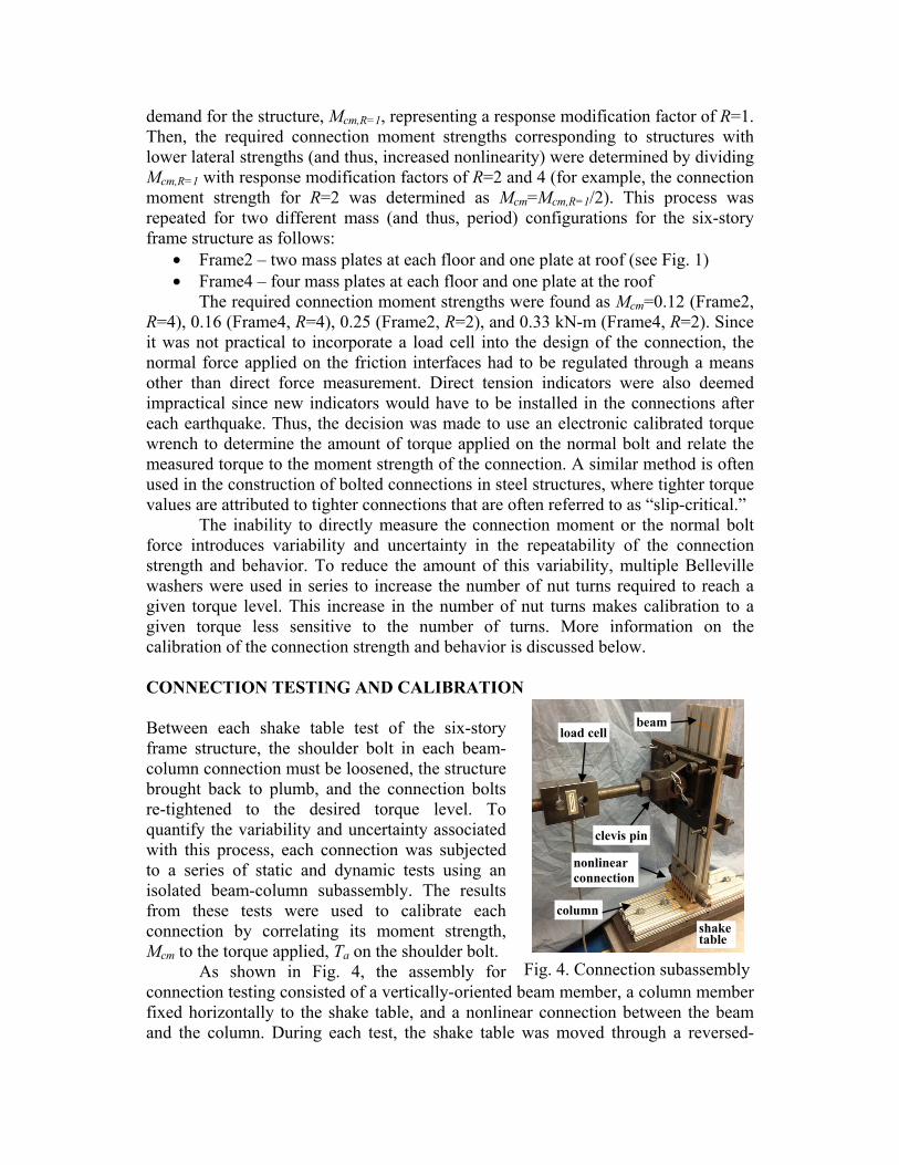
CONNECTION TESTING AND CALIBRATION Between each shake table test of the six-story frame structure, the shoulder bolt in each beam-column connection must be loosened, the structure brought back to plumb, and the connection bolts re-tightened to the desired torque level. To quantify the variability and uncertainty associated with this process, each connection was subjected to a series of static and dynamic tests using an isolated beam-column subassembly. The results from these tests were used to calibrate each connection by correlating its moment strength, Mcm to the torque applied, Ta on the shoulder bolt.
As shown in Fig. 4, the assembly for connection testing consisted of a vertically-oriented beam member, a column member fixed horizontally to the shake table, and a nonlinear connection between the beam and the column. During each test, the shake table was moved through a reversed-
Fig. 4. Connection subassembly
column
clevis pin
beam load cell
nonlinear connection
shaketable

cyclic displacement history at different excitation amplitudes and frequencies. A pin-ended threaded rod with an intermediate load cell was connected to the beam at a distance of 375 mm from the column face (which is close to the midspan location of the beams in the six-story structure). The other end of the threaded rod assembly was connected to a rigid steel reaction frame to keep the beam stationary while measuring the resulting force as the nonlinear connection was rotated through the displacements of the shake table. Displacement transducers mounted to an adjacent wall (isolated from the reaction frame) were used to measure the beam chord rotation, θb.
Each connection subassembly was first subjected to a slow quasi-static test with two displacement cycles at six different amplitudes up to a maximum beam chord rotation of θb=2.2% as shown in Fig. 5. The rotation of 2.2% was selected based on the largest beam chord rotation of 2.1% (taken from the column face to the beam midspan) from the linear-elastic analytical model of Frame2 subjected to the 39 ground motion records in Suite GM[Uns]. The median of the maximum beam chord rotation values from the 39 records was θ =0.74%.
The quasi-static tests were conducted using a constant velocity that corresponded to an excitation frequency range of 0.33 to 0.03 Hz during the applied loading history. To investigate the connection response under dynamic loading, a Fourier analysis was conducted on the beam chord rotation time histories from the linear-elastic model of Frame2 under Suite GM[Uns]. The dominant frequencies of beam chord rotation were determined to be 2.3, 3.8, 4.4, and 5.0 Hz, resulting in the dynamic testing combinations shown in Table 1. For each combination of beam chord rotation and excitation frequency in Table 1, the subassembly was subjected to 10 loading cycles, resulting in a loading sequence of 70 cycles. As shown in Fig. 5, this dynamic loading sequence was applied immediately following the quasi-static loading of each connection (i.e., total loading sequence of 12 quasi-static + 70 dynamic = 82 displacement cycles).
Sample connection moment, Mc versus beam chord rotation, θb behaviors from the beam-column subassembly tests are shown in Fig. 6. The connection moment in these plots was determined by multiplying the measured load cell force with the distance to the column face (375 mm). Fig. 6(a) shows the behavior under the full combined quasi-static and dynamic loading sequence of a connection with an applied torque of Ta=0.079 kN-m on the shoulder bolt. Similar results are shown in Fig. 6(b) for the same connection with an applied torque of Ta=0.164 kN-m. As is also shown in Fig. 6(c) for a series of quasi-static test results, the connection moment strength increases as the torque on the shoulder bolt is increased. The connection strength under quasi-static loading is larger than the strength under dynamic loading, which can be attributed to the greater static coefficient of friction, μstatic as compared with the kinetic friction, μkinetic [see Fig. 2(a)]. No difference can be observed in the moment-
Fig. 5. Combined test history.
Table 1: Dynamic tests. Beam ChordRotation (%)
Excitation Frequency (Hz)
0.27 2.3 - 4.35 -0.69 2.3 3.8 4.35 51.11 - - 4.35 -
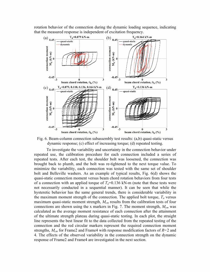
rotation behavior of the connection during the dynamic loading sequence, indicating that the measured response is independent of excitation frequency.
Fig. 6. Beam-column connection subassembly test results: (a,b) quasi-static versus
dynamic response; (c) effect of increasing torque; (d) repeated testing.
To investigate the variability and uncertainty in the connection behavior under repeated use, the calibration procedure for each connection included a series of repeated tests. After each test, the shoulder bolt was loosened, the connection was brought back to plumb, and the bolt was re-tightened to the next torque value. To minimize the variability, each connection was tested with the same set of shoulder bolt and Belleville washers. As an example of typical results, Fig. 6(d) shows the quasi-static connection moment versus beam chord rotation behaviors from four tests of a connection with an applied torque of Ta=0.136 kN-m (note that these tests were not necessarily conducted in a sequential manner). It can be seen that while the hysteretic behavior has the same general trends, there is considerable variability in the maximum moment strength of the connection. The applied bolt torque, Ta versus maximum quasi-static moment strength, Mcm results from the calibration tests of four connections are shown using the x markers in Fig. 7. The moment strength, Mcm was calculated as the average moment resistance of each connection after the attainment of the ultimate strength plateau during quasi-static testing. In each plot, the straight line represents the best linear fit to the data collected from the repeated testing of the connection and the red circular markers represent the required connection moment strengths, Mcm for Frame2 and Frame4 with response modification factors of R=2 and 4. The effects of the observed variability in the connection strength on the dynamic response of Frame2 and Frame4 are investigated in the next section.
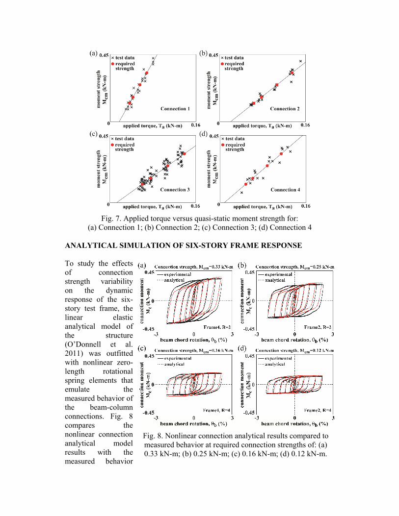
Fig. 7. Applied torque versus quasi-static moment strength for:
(a) Connection 1; (b) Connection 2; (c) Connection 3; (d) Connection 4 ANALYTICAL SIMULATION OF SIX-STORY FRAME RESPONSE To study the effects of connection strength variability on the dynamic response of the six-story test frame, the linear elastic analytical model of the structure (O’Donnell et al. 2011) was outfitted with nonlinear zero-length rotational spring elements that emulate the measured behavior of the beam-column connections. Fig. 8 compares the nonlinear connection analytical model results with the measured behavior
Fig. 8. Nonlinear connection analytical results compared to measured behavior at required connection strengths of: (a) 0.33 kN-m; (b) 0.25 kN-m; (c) 0.16 kN-m; (d) 0.12 kN-m.
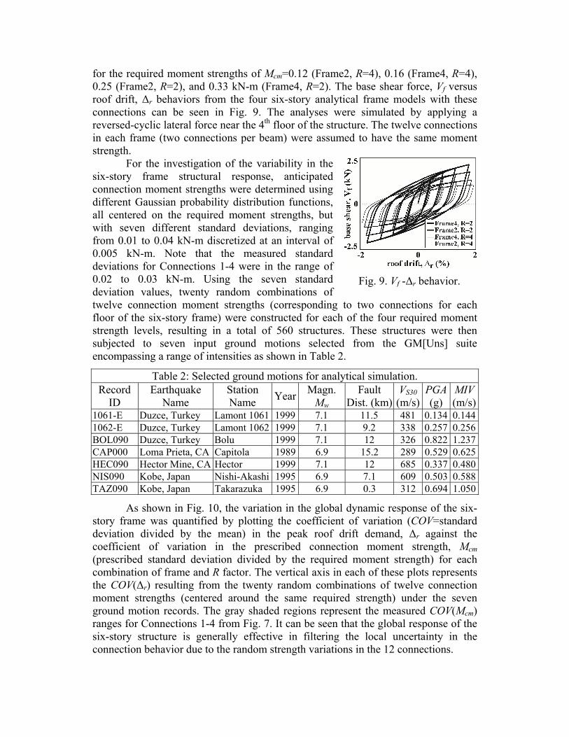
for the required moment strengths of Mcm=0.12 (Frame2, R=4), 0.16 (Frame4, R=4), 0.25 (Frame2, R=2), and 0.33 kN-m (Frame4, R=2). The base shear force, Vf versus roof drift, Δr behaviors from the four six-story analytical frame models with these connections can be seen in Fig. 9. The analyses were simulated by applying a reversed-cyclic lateral force near the 4th floor of the structure. The twelve connections in each frame (two connections per beam) were assumed to have the same moment strength.
For the investigation of the variability in the six-story frame structural response, anticipated connection moment strengths were determined using different Gaussian probability distribution functions, all centered on the required moment strengths, but with seven different standard deviations, ranging from 0.01 to 0.04 kN-m discretized at an interval of 0.005 kN-m. Note that the measured standard deviations for Connections 1-4 were in the range of 0.02 to 0.03 kN-m. Using the seven standard deviation values, twenty random combinations of twelve connection moment strengths (corresponding to two connections for each floor of the six-story frame) were constructed for each of the four required moment strength levels, resulting in a total of 560 structures. These structures were then subjected to seven input ground motions selected from the GM[Uns] suite encompassing a range of intensities as shown in Table 2.
Table 2: Selected ground motions for analytical simulation. Record
ID Earthquake
Name Station Name Year Magn.
Mw Fault
Dist. (km)VS30
(m/s) PGA (g)
MIV(m/s)
1061-E Duzce, Turkey Lamont 1061 1999 7.1 11.5 481 0.134 0.1441062-E Duzce, Turkey Lamont 1062 1999 7.1 9.2 338 0.257 0.256BOL090 Duzce, Turkey Bolu 1999 7.1 12 326 0.822 1.237CAP000 Loma Prieta, CA Capitola 1989 6.9 15.2 289 0.529 0.625HEC090 Hector Mine, CA Hector 1999 7.1 12 685 0.337 0.480NIS090 Kobe, Japan Nishi-Akashi 1995 6.9 7.1 609 0.503 0.588TAZ090 Kobe, Japan Takarazuka 1995 6.9 0.3 312 0.694 1.050
As shown in Fig. 10, the variation in the global dynamic response of the six-story frame was quantified by plotting the coefficient of variation (COV=standard deviation divided by the mean) in the peak roof drift demand, Δr against the coefficient of variation in the prescribed connection moment strength, Mcm (prescribed standard deviation divided by the required moment strength) for each combination of frame and R factor. The vertical axis in each of these plots represents the COV(Δr) resulting from the twenty random combinations of twelve connection moment strengths (centered around the same required strength) under the seven ground motion records. The gray shaded regions represent the measured COV(Mcm) ranges for Connections 1-4 from Fig. 7. It can be seen that the global response of the six-story structure is generally effective in filtering the local uncertainty in the connection behavior due to the random strength variations in the 12 connections.
Fig. 9. Vf -Δr behavior.

SUMMARY AND CONCLUSIONS
This paper describes the design and calibration of a reusable, rotational nonlinear beam-column connection as part of a small-scale six-story building frame specimen for use in an experimental ground motion scaling study. It is shown that the behavior of the connection is independent of excitation frequency and that it can be modeled using a simple zero-length spring element. The moment strength of the connection can be prescribed using the torque applied on the shoulder bolt; however, considerable variability in strength is observed under repeated use of the connection. Based on an analytical simulation, it is found that the multi-story frame structure is generally effective in filtering the uncertainty in the connection behavior such that the variation in the global response of the frame is often less than that of the connections.
ACKNOWLEDGEMENTS
This research is funded by the National Science Foundation (NSF) under Grant No. CMMI 0928662. The support of Dr. M.P Singh, former NSF Program Director, and Dr. K.I. Mehta, current NSF Program Director, is gratefully acknowledged. The authors would like to acknowledge the project advisory panel, which includes Paulo Bazzurro, AIR Worldwide Corporation; Sigmund Freeman, Wiss, Janney, Elstner Associates, Inc.; Vladimir Graizer, U.S. Nuclear Regulatory Commission; Farzad Naeim, John A. Martin and Associates, Inc.; and Thomas Sabol, Englekirk & Sabol Consulting Structural Engineers, Inc. The authors also thank Bob St. Henry of NEFF Engineering for his help in the design of the test frame. The opinions, findings, and
Fig. 10. Effect of variability in connection strength on the peak roof drift demands:
(a) Frame4, R=2; (b) Frame2, R=2; (c) Frame4, R=4; (d) Frame2, R=4.
conclusions in the paper are those of the authors and do not necessarily reflect the views of the organizations or individuals above. REFERENCES Alavi, B. and Krawinkler, H. “Consideration of near-fault ground motion effects in
seismic design,” 12th World Conference on Earthquake Engin., Paper No. 2665, Auckland, New Zealand, 2000.
Baez, J. and Miranda, E., “Amplification factors to estimate inelastic displacement demands for the design of structures in the near field,” 12th World Conference on Earthquake Engineering, Paper No. 1561, Auckland, New Zealand, 2000.
Chopra, A.K. and Chinatanapakdee, C., “Inelastic deformation ratios for design and evaluation of structures: single-degree-of-freedom bilinear systems,” J. of Structural Engineering, 130(9), 2004, 1304-1319.
Kalkan, E. and Chopra, A.K., “Practical guidelines to select and scale earthquake records for nonlinear response history analysis of structures,” U.S. Geological Survey Open-File Report 2010-1068, 2010, 126 pp. (available online at http://nsmp.wr.usgs.gov/ekalkan/MPS/index.html)
Kalkan, E. and Chopra, A.K., “Modal-pushover-based ground motion scaling procedure,” J. of Structural Engineering, 137(3), 2011, 298-310.
Kalkan, E. and Kwong, N.S., “Documentation for assessment of modal pushover-based scaling procedure for nonlinear response history analysis of “ordinary standard” bridges,” U.S. Geological Survey Open-File Report 2010-1328, 2011, 58 pp. (available online at http://pubs.usgs.gov/of/2010/1328/).
Kurama, Y. and Farrow, K., “Ground motion scaling methods for different site conditions and structure characteristics,” Earthquake Engineering & Structural Dynamics, 32(15), 2003, 2425-2450.
Luco, N. and Cornell, A., “Structure-specific scalar intensity measures for near-source and ordinary earthquake ground motions,” Earthquake Spectra, 23(2), 2007, 357-392.
Martinez-Rueda, J., “Scaling procedure for natural accelerograms based on a system of spectrum intensity scales,” Earthquake Spectra, 14, 1998, 135-152.
Miranda, E., “Evaluation of site-dependent inelastic seismic design spectra,” J. of Structural Engineering, 119(5), 1993, 1319-1338.
Morgen, B. and Kurama, Y., “Characterization of two friction interfaces for use in seismic damper applications,” Materials and Structures, 42(1), 2009, 35-49.
Morgen, B. and Kurama, Y., “A friction damper for post-tensioned precast concrete beam-to-column joints,” PCI J., 49(4), 2004, 112-133.
Nau, J. and Hall, W., “Scaling methods for earthquake response spectra,” J. of Structural Engineering, 110, 1984, 91-109.
O’Donnell, A., Beltsar, O., Kurama, Y., Kalkan, E., and Taflanidis, A., “Evaluation of ground motion scaling methods for analysis of structural systems,” ASCE Structures Congress, Las Vegas, Nevada, 2011.
Shome, N. and Cornell, C., “Normalization and scaling accelerograms for nonlinear structural analysis,” 6th U.S. National Conf. on Earthquake Engin., Seattle, WA, 1998. (CD-ROM)
Vidic, T., Fajfar, P., and Fischinger, M., “Consistent inelastic design spectra: strength and displacement,” Earthquake Engineering & Structural Dynamics, 23, 1994, 507-521.