
CAL_FAD
79
ISO/IEC 17025 Field Application Document Calibration Supplementary Requirements for Accreditation May 2012
-
Upload
leonardo-vence-ordonez -
Category
Documents
-
view
49 -
download
1
Transcript of CAL_FAD

ISO/IEC 17025 Field Application Document Calibration Supplementary Requirements for Accreditation May 2012

© Copyright National Association of Testing Authorit ies, Australia 2012 This publication is protected by copyright under the Commonwealth of Australia Copyright Act 1968. NATA’s accredited facilities or facilities seeking accreditation may use or copy this publication or print or email this publication internally for accreditation purposes. Individuals may store a copy of this publication for private non-commercial use or copy a reasonable portion of this publication in accordance with the fair dealing provisions in Part III Division 3 of the Copyright Act 1968. You must include this copyright notice in its complete form if you make a copy of this publication. Apart from these permitted uses, you must not modify, copy, reproduce, republish, frame, upload to a third party, store in a retrieval system, post, transmit or distribute this content in any way or any form or by any means without express written authority from NATA.

Calibration Field Application Document - Supplementary Requirements for Accreditation
May 2012 Page 3 of 79
Contents
SECTION 1: Introduction ............................. .................................................................................................................... 4 Scope ........................................................................................................................................................... 4 Applicability................................................................................................................................................... 5 Administration............................................................................................................................................... 5 Terminology and presentation ...................................................................................................................... 5 Legislation .................................................................................................................................................... 6 Safety ........................................................................................................................................................... 6
SECTION 2: Accreditation procedures................. .......................................................................................................... 6 The role of the authorised representative ..................................................................................................... 6 Facility contact person .................................................................................................................................. 7 Fees for services .......................................................................................................................................... 7 Preliminary steps .......................................................................................................................................... 7 Advisory visit................................................................................................................................................. 7 Document review.......................................................................................................................................... 7 Application for accreditation.......................................................................................................................... 8 Assessment .................................................................................................................................................. 8 Granting accreditation................................................................................................................................... 9 Scope of accreditation .................................................................................................................................. 9 After accreditation......................................................................................................................................... 9 Variations to scope of accreditation............................................................................................................ 10 Approved signatories .................................................................................................................................. 10 Delegation of signatory approval ................................................................................................................ 11 Signatory interviews.................................................................................................................................... 12 Reports and use of the NATA endorsement ............................................................................................... 12 Proficiency testing....................................................................................................................................... 12 Non-compliance with accreditation requirements ....................................................................................... 12 Provision of information on scope of accreditation and approved signatories ............................................ 13 Complaints and feedback ........................................................................................................................... 13 Confidentiality ............................................................................................................................................. 13 Privacy........................................................................................................................................................ 13 Authorised representative........................................................................................................................... 13 Facility contact ............................................................................................................................................ 14 Facility personnel........................................................................................................................................ 14 Disclosure of personal information by applicant and accredited facilities at assessments.......................... 14
SECTION 3: Supplementary requirements for accreditati on................................................. ..................................... 14
ANNEX 3.1: Acoustic and Vibration Measurement ....... .............................................................................................. 26
ANNEX 3.2: Mass and Related Quantities............. ....................................................................................................... 28
ANNEX 3.3: Dimensional Metrology ................... .......................................................................................................... 30
ANNEX 3.4: Electrical Metrology ..................... ............................................................................................................. 30
ANNEX 3.5: Temperature Metrology................... .......................................................................................................... 31
ANNEX 3.6: Optics and Radiometry ................... .......................................................................................................... 35
SECTION 4: Measurement traceability ................. ........................................................................................................ 48 Definitions................................................................................................................................................... 48 Calibration and checking intervals .............................................................................................................. 49 Equipment Table for Reference use ........................................................................................................... 50 General Equipment Table........................................................................................................................... 60
SECTION 5: Classes of test.......................... ................................................................................................................. 66
SECTION 6: References............................... .................................................................................................................. 76

Calibration Field Application Document - Supplementary Requirements for Accreditation
May 2012 Page 4 of 79
SECTION 1: Introduction
Scope
The general requirements for the competence of testing and calibration facilities are described in AS ISO/IEC 17025: 2005 General requirements for the competence of testing and calibration laboratories, hereafter referred to as ‘ISO/IEC 17025’. These requirements are designed to apply to all types of testing and calibration and therefore often need to be interpreted with respect to the type of calibration or testing concerned and the techniques involved. This Field Application Document (FAD) provides an explanation of the application of ISO/IEC 17025 for calibration facilities and includes a description of the NATA accreditation procedures applied in this field. Facilities must comply with this document, all relevant clauses of ISO/IEC 17025, the NATA Rules and relevant statutory requirements. Additional information relating to specific areas of testing, or changes or additions to accreditation requirements, or policies may be issued from time to time in the form of Technical or Policy Circulars. These shall supersede any previous requirements where indicated. The FAD must therefore be read in conjunction with all of these references and are included in the NATA Accreditation Requirements (NAR). The NATA Accreditation Requirements (NAR) are made up of a number of documents, which are available for download as a zipped file from the 'Accreditation Publications' section of the NATA website, www.nata.com.au. The documents comprising the NAR are: 1. The relevant standard (e.g. AS ISO/IEC 17025) for which accreditation is held or sought. This is not
supplied by NATA and must be obtained by the facility. The following table provides information about where to obtain the applicable standards or documents.
Standard/document Field/Program Organisation Websi te
AS ISO/IEC 17025 Laboratory Accreditation
Supplier of Australian standards
AS/NZS ISO/IEC 17020
Inspection Supplier of Australian standards
ISO 15189 Medical Testing Supplier of Australian standards
RANZCR Standards Medical Imaging RANZCR www.ranzcr.edu.au
ISO/IEC 17043 Proficiency Testing Scheme Providers
Supplier of ISO standards
ISO Guide 34 Reference Material Producers
Supplier of ISO standards
OECD Principles of Good Laboratory Practice
GLP Recognition OECD Environment Directorate Environmental Health and Safety Division
www.oecd.org/env/glp
2. Relevant field application document (FAD) i.e. this document, for the program/field in which accreditation is held or sought (available from the NATA website).
3. NATA Rules (available from the NATA website).
4. Current Policy/Technical Circulars (where relevant) (available from the NATA website).
5. Some fields/programs have additional documents that also form part of the accreditation requirements which are referenced in the relevant field application document (FAD).

Calibration Field Application Document - Supplementary Requirements for Accreditation
May 2012 Page 5 of 79
Technical Notes are also available to assist facilities in relation to particular technical matters. They are intended to provide guidance and therefore do not contain requirements for accreditation. Copies may be obtained from NATA offices or from our website. A copy of the NATA Accreditation Requirements must be readily available to staff working in a NATA accredited or applicant facility. Other informative documents are also available from the NATA website, such as: 1. About NATA and Accreditation
2. Information Papers
3. Proficiency Testing information
Applicability
The accreditation criteria are applicable to all facilities, irrespective of size, range of testing/calibration activities or number of personnel. It should, however, be noted that it is not possible to set rigid requirements for all aspects of a facility’s operation. Some flexibility is necessary so that each facility’s unique situation can be considered. The acceptability (or otherwise) of certain practices can therefore only be determined by assessment. Information on the assessment process is contained in Section 2. ISO/IEC 17025 Field Application Documents are available for all of NATA’s accreditation fields, as listed below. Biological Testing Information and Communications Technology Testing Chemical Testing Mechanical Testing Construction Materials Testing Non-destructive Testing Forensic Science Performance and Approvals Testing * Veterinary Testing * Previously Calibration and Performance & Approvals Testing were combined under the field of Measurement and Science Technology.
Application documents are also available for NATA’s other programs including accreditation for inspection, medical testing, medical imaging, proficiency testing scheme providers, reference materials producers and research & development. Additionally, an interpretation document is available for GLP recognition against the OECD principles.
Administration
NATA’s accreditation activities are administered, under the Board’s direction, by the relevant field/program Accreditation Advisory Committee. The current NATA Rules outline the functions of the Board and the Accreditation Advisory Committees.
Terminology and presentation
The clause numbers in Section 3 of this document follow those of ISO/IEC 17025 but since not all clauses require interpretation the numbering may not be continuous. It is recognised that not all testing or calibration activities are performed in a ‘laboratory’. Accordingly, the expression ‘facility’ is used throughout this document. The words ‘shall’ and ‘must’ are used interchangeably throughout this document and describe mandatory criteria for accreditation. The word ‘should’ is used where guidance is provided but does not preclude other acceptable practices. Where a smaller size font has been used i.e. a ‘Note’, this indicates a matter of an advisory or informative nature. Any references to the NATA Rules, Fee Schedule, Technical Policies etc imply the current version of such documents. Where the words ‘policy’ and ‘procedure’ are used in ISO/IEC 17025 it is possible that one document may meet the requirements of the standard. This will be determined at assessment.

Calibration Field Application Document - Supplementary Requirements for Accreditation
May 2012 Page 6 of 79
Legislation
It is the responsibility of each facility to ensure that it complies with all relevant legislation. Legislative requirements may take precedence over, or provide additional criteria to those detailed in this document. It is also strongly recommended that facilities hold copies of relevant legislation.
Safety
NATA does not define mandatory safety measures but does draw attention to any unsafe practices that are observed in the course of an assessment. Facilities are, however, encouraged to apply the relevant sections of AS2243 Safety in Laboratories. When clauses related to safety are written into test methods covered by the accreditation, these must be observed and are subject to assessment.
SECTION 2: Accreditation procedures
The following information is provided to assist facilities who seek or hold accreditation or wish to extend the scope of their accreditation. General information is also provided with regard to NATA’s policies and procedures. It should be noted that there are some differences between the fields/programs with regard to the order in which these steps are followed. Hence, this section may vary from other Application Documents which reflects relevant but different emphases in the various activities NATA accreditation covers, or limitations that have been placed on the NATA process by outside influences, such as regulatory or industry-specific requirements. Where an organisation may require accreditation in a number of different fields, every attempt is made to harmonise and coordinate accreditation activities. Where applications or accreditations are required that include non-testing/calibration NATA accreditation activities (such as the Reference Material Producers Accreditation Program, Proficiency Testing Scheme Providers Accreditation, Inspection Accreditation or GLP Recognition) every effort is also made to appropriately coordinate activities. Corporate accreditation is available in defined circumstances to assist this process. A Policy Circular is available explaining this process and can be obtained from our offices or the NATA website. There may also be a need to vary the steps detailed below in the case of applications from overseas facilities. Once again, every attempt is made to ensure the accreditation process is carried out in the most efficient and effective way for all parties concerned. Clause 1.6 of ISO/IEC 17025 states that facilities that comply with ISO/IEC 17025 meet the ‘principles of ISO 9001’. Facilities interested in making a statement regarding this issue for their customers should refer to the Joint ISO-ILAC-IAF Communiqué on the Management Systems Requirements of ISO/IEC 17025: 2005 available from the ‘Publications – International documents’ section of the NATA website. In conducting assessments, however, NATA cannot accept a facility’s ISO 9000 certification as the sole statement of compliance with the management requirements of ISO/IEC 17025. ISO 9001: 2008 is an outcome based standard and has fewer requirements for documented procedures and records. It is also necessary to consider how the system is applied at a technical level. Therefore, the management system requirements of ISO/IEC 17025 will still be assessed in these situations.
The role of the authorised representative
The authorised representative is the person nominated by the facility to be its representative in all matters relating to the application or accreditation and is the recognised official contact with NATA. Nomination is made in the appropriate place on the application form or when changes are required thereafter, on the ‘Nomination of New Authorised Representative’ form available for this purpose. The rights and legal obligations of the authorised representative are detailed in the NATA Rules. At a practical level, the authorised representative is normally a senior staff member who is in a position to make decisions regarding the facility’s accreditation and to effectively communicate with facility staff. The authorised representative may also choose to direct NATA to other facility personnel with whom relevant issues may be discussed.

Calibration Field Application Document - Supplementary Requirements for Accreditation
May 2012 Page 7 of 79
The authorised representative is required to notify NATA within 14 days if: • the name or ownership of the facility changes; • there are changes in duties or departures of key staff; or • significant changes occur to the functions or accommodation of the facility.
Facility contact person
Recognising that the authorised representative is not necessarily the most appropriate person to answer day to day and technical queries regarding an accredited facility’s activities, NATA provides facilities the opportunity to nominate a person to deal with technical and other enquiries. This person can, however, also be the authorised representative.
Fees for services
The various parts of the accreditation process where charges are levied are indicated in this document. Specific information on charges can be obtained from our current Fee Schedule (available from the NATA website) or by contacting a NATA office.
Preliminary steps
The facility is encouraged to hold discussions with relevant NATA technical staff prior to lodging a formal application for accreditation. When seeking accreditation, facility staff should also familiarise themselves with the NATA Accreditation Requirements (NAR). The NAR can be obtained from the NATA website.
Advisory visit
An advisory visit to the facility can be undertaken by a NATA technical staff officer (lead assessor) to further discuss the assessment process and to explain the significant requirements that relate to accreditation. Such a visit includes an informal review of the facility which can help determine its state of readiness for accreditation. It should, however, be remembered that the NATA lead assessor, whilst an experienced scientist, is not a technical assessor. Accordingly, the formal assessment (refer below) is the process whereby compliance with the accreditation requirements is determined. Following the visit, a written report is provided which summarises the key points of discussion. An advisory visit is usually conducted prior to an application for accreditation being submitted, however, the most appropriate timing for such a visit will be a matter for negotiation between the facility and the NATA lead assessor. While an advisory visit is not mandatory it is strongly recommended that facilities avail themselves of this service prior to applying for accreditation. There are of course cases in which facilities have good knowledge of NATA through existing contacts or accreditations. In such cases, the merits of an advisory visit should still be discussed with relevant NATA technical staff. Prior to an advisory visit, the facility will be asked to provide relevant documentation for review. The NATA lead assessor will advise exactly what information is required. This activity is known as 'document review' and is described below. A fee is levied for an advisory visit in accordance with NATA’s Fee Schedule.
Document review
Depending on the state of readiness of the facility for accreditation, it will be asked (either prior to an advisory visit or after an advisory visit, but before the formal on-site assessment), to submit a copy of its proposed scope of accreditation, current management system documentation, calibration and/or test procedures and information on staff so that a document review can be undertaken.

Calibration Field Application Document - Supplementary Requirements for Accreditation
May 2012 Page 8 of 79
A document review is most often conducted by the NATA lead assessor who will be involved in the assessment of the facility. The document review provides a comparison of the facility’s documentation and procedures with the accreditation requirements as detailed in the NAR. The NATA lead assessor also makes note of particular references within the facility’s documented system that require review at the assessment or areas that appear to require further explanation or investigation. Written feedback will be provided on the findings of the document review. Depending on the extent of the action required the facility may be asked to provide further information prior to the assessment or this information will be sought at the assessment. A fee is levied for the document review in accordance with NATA’s Fee Schedule.
Application for accreditation
Applications for accreditation may be made by any legally identifiable organisation and must be made on the prescribed application form. This form will be provided at an appropriate time with regard to the intended time of application. The application must be accompanied by the current application fee in accordance with NATA’s Fee Schedule.
Assessment
Compliance of an applicant with the accreditation requirements is determined primarily by an on-site assessment. The objective of an assessment is to establish whether the facility can competently perform the activities for which accreditation is being sought. The NATA assessment team is required to investigate the operation of the facility against the criteria detailed in the NATA Accreditation Requirements. The assessment team reports its findings to both the facility seeking accreditation and the relevant Accreditation Advisory Committee (AAC). The assessment team is comprised of at least one NATA lead assessor and one or more specialist volunteer technical assessors. Review of the management system is essentially conducted by the NATA lead assessor whilst the volunteer assessors concentrate on the technical activities performed by the facility. The size of the assessment team is dependent upon the areas that must be covered in the course of the assessment. Technical assessors are chosen according to their specialist knowledge and are matched as closely to the activities of the facility as is possible. Consideration is given to possible concerns about conflicts of interest in selecting assessors. Assessments will generally take at least one working day and may extend over a number of days depending on the range of activities to be covered. Facility staff will be called upon to discuss, with the technical assessors, technical issues relating to measurements and tests that are in progress or carried out by the facility. Occasionally, such discussion may be hypothetical. NATA may also request prior to the assessment, or in the course of the assessment, that particular procedures or tests be demonstrated. Facilities should ensure that relevant staff are available during an assessment and should expect all activities for which accreditation is sought to be covered in some way. Where consultants are associated with a facility, NATA reserves the right to contact these persons to establish their level of involvement if they are not present at the assessment.

Calibration Field Application Document - Supplementary Requirements for Accreditation
May 2012 Page 9 of 79
An exit interview or meeting is held at the conclusion of the assessment at which the assessment findings are presented by the NATA lead assessor. It is the prerogative of the facility to decide which of their staff should attend this meeting. Generally, the authorised representative would be expected to attend as well as relevant senior staff. The purpose of the exit meeting is to allow frank and open discussion about the findings of the assessment. Facilities are strongly encouraged to clarify issues they consider may have been misunderstood by the assessment team and to seek clarification about assessment findings where this may be necessary. Where the assessment team and facility do not agree on a finding or the emphasis placed on an issue, this will be noted by the NATA lead assessor and considered during the report review process (refer below). Further information may also be requested by NATA and included in the final report where this information was not available during the assessment. An interim written report is usually left on the day. This report is subsequently reviewed by NATA senior staff and where relevant, the AAC, prior to the issue of the final report to the facility. This review ensures that the assessment team findings are appropriate and in accordance with the accreditation requirements, that evidence gathered at the assessment support the findings and that there is consistent interpretation and appropriate application of the accreditation requirements. Occasionally, a specific issue raised in the report may also be referred for review to other technical experts (not members of the AAC) where further advice is sought. In such cases, the identity of the facility concerned is kept confidential. Where necessary, the final report will detail any non-conformities needing to be addressed by the facility to allow accreditation to be recommended. In these cases, the facility will be asked to provide NATA with the necessary evidence that action has been taken, as claimed. Occasionally, the AAC may recommend that a further visit by a NATA lead assessor or that another assessment be conducted. There are a number of reasons for this, including concerns about the competence of the facility, the inability to assess certain aspects of the facility during the scheduled visit because of lack of availability of key staff, or to review the effective implementation of the corrective action taken as a result of the assessment. The same procedures for assessment will be followed but may concentrate on only the area(s) found to be deficient. Fees are levied for the conduct of assessments in accordance with NATA’s Fee Schedule.
Granting accreditation
NATA’s Chief Executive grants accreditation following a recommendation by the relevant AAC. This recommendation is made when the facility has met all the requirements for accreditation. The authorised representative is formally advised of the granting of the accreditation and issued with a certificate and the scope of accreditation.
Scope of accreditation
Accreditation is described by classes and sub-classes of test. The collective expression, or scope of a facility’s accreditation, is known as its ‘scope of accreditation’. These classes and sub-classes are fixed descriptors, free text being used to qualify or amplify the scope as necessary. Where the scope of accreditation of a facility cannot be adequately described by existing descriptors, the AAC may from time to time establish new classes and/or sub-classes of test. A copy of the classes of test available in the field of calibration is provided in Section 5 of this document. Classes of test are, however, revised from time to time so for the most current version please contact a NATA office or visit our website. Applications for accreditation may be made for one or more classes of test, or for one or more subclasses within a class of test. The scopes of accreditation of all NATA accredited facilities are available on the NATA website.
After accreditation
NATA accredited facilities must continue to comply with all accreditation requirements detailed in the NATA Accreditation Requirements. In order to ensure continued compliance with these requirements, scheduled visits to facilities are arranged. Generally the assessment cycle is three years which includes a surveillance visit at 18 months followed by a reassessment at 36 months.

Calibration Field Application Document - Supplementary Requirements for Accreditation
May 2012 Page 10 of 79
Shorter intervals to a facility may also be specified by the relevant Accreditation Advisory Committee. Such intervals will be determined on the significance of issues identified during a visit to a facility and/or any doubt over a facility’s continuing compliance with the accreditation requirements. Reassessments follow the same general process as the initial assessment. The scope of review covers all of the facility’s technical activities, however only selected elements of the management system against the accreditation requirements detailed in the NAR. A document review is generally not conducted prior to a scheduled reassessment. Extensions to the scope of accreditation and/or signatories requested as part of a scheduled reassessment will only be accommodated where such requests do not compromise the purpose of the reassessment (see Variations to scope of accreditation). Fees will be charged where additional resources and time are required to accommodate the request as part of a scheduled reassessment. NATA technical staff will provide further information. Surveillance visits are conducted by a NATA lead assessor and involves review of the management system in full (including a document review) and selected technical elements against the accreditation requirements detailed in the NAR. Extensions to the scope of accreditation will normally not be considered as such visits do not include technical assessors. Facilities must respond to reassessment and surveillance visit findings by the nominated response date, otherwise the status of their accreditation will be reviewed. The annual membership fees payable by accredited facilities generally cover the costs of reassessments and surveillance visits. Requests for variations to the scope of accreditation outside routine reassessments may also be considered (see Variations to scope of accreditation). Unscheduled visits may be conducted to investigate a complaint or following the receipt of information that casts doubt over the facility’s continuing compliance with the accreditation requirements. At such visits, specific activities may be targeted for review rather than the entire facility operation.
Variations to scope of accreditation
Accredited facilities may request variations to their scope of accreditation or signatory approvals at any time once accredited. NATA technical staff will provide direction on the information required, the process that will be followed and the charges that will be levied. Extensions to the scope of a facility’s accreditation or signatory approvals may be accommodated at the same time as a scheduled routine reassessment but only where review of the additional activity(ies) will not compromise the purpose of the reassessment (which is to review the existing scope of accreditation to determine ongoing compliance with the accreditation requirements). Adequate notice by the facility must also be provided in order for the variation to be considered. Variations to the scope of accreditation must be supported by relevant documentation in advance of the assessment (e.g. proposed scope, calibration or test procedures, sample worksheet, report and uncertainty calculations). Fees will be charged for extensions to the scope of accreditation conducted during a routine reassessment where additional effort is necessary (e.g. additional time and/or technical assessors are required). In general, an extension to the scope of accreditation will only be granted once any relevant issues raised at the previous assessment (e.g. reassessment, surveillance visit), which apply to the activities requested by the scope extension, have been addressed.
Approved signatories
NATA grants formal approval to facility staff to authorise test reports or calibration certificates for work covered by the scope of accreditation. Such personnel are known as ‘approved signatories’ and their capability to undertake this role is determined primarily at assessment. Approved signatories assume responsibility for the technical validity and accuracy of all information contained in test reports and/or calibration certificates.

Calibration Field Application Document - Supplementary Requirements for Accreditation
May 2012 Page 11 of 79
A facility must have approved signatories to cover the complete range of its scope of accreditation. The accreditation will be suspended for any parts of the scope for which approved signatories are no longer available. (See Delegation of signatory approval below) Individuals may be approved as signatories for all or part of the facility’s scope of accreditation. Signatory approval is not a personal qualification and is not transferable from one facility to another without approval having being granted at each facility. Signatory approval is available to consultants to the facility provided that they have the knowledge necessary to allow them to be approved as signatories and have authority over the testing and/or calibration activities. It is expected that all signatories (and other reporting officers formally designated/approved as such by NATA) will be present at every reassessment and surveillance visit for review of that approval. In cases where only a partial reassessment of the facility is conducted, individuals need only be present for the assessment of those areas of the facility relevant to their signatory approval. Authorised representatives shall therefore ensure the availability of all such individuals when assessment arrangements are being discussed with NATA. It is however, recognised that there will be occasions when signatories will not be able to be present at a given assessment due to unforeseen circumstances. Signatories not present at an assessment are noted as such in the ‘Approved Signatories’ section of the assessment report. Any signatory not present at a scheduled reassessment must be present at the next routine visit to the facility (which covers the area(s) relevant to the approval). Signatories not present for two consecutive scheduled visits will have their signatory approval withdrawn. Signatory approval can be reinstated following a signatory interview for which the facility will be charged or at the next scheduled reassessment (see Section 2, Variations to scope of accreditation). The specific requirements for approved signatories are covered in Section 3.
Delegation of signatory approval
Facilities may select to delegate the approval of their ‘NATA approved signatory(ies)’ to staff who they deem as appropriate to authorise results for test reports or calibration certificates for work covered by the scope of accreditation. Where regulatory requirements specify NATA approved signatories, the onus is on the facility to determine whether delegation of signatory approval is permitted under the requirements. Where the facility’s scope of accreditation (either in full of part) is no longer covered by a NATA approved signatory(ies), the facility may operate with only delegated signatories for a period not exceeding six months. NATA must be informed in writing at least three months before the six month period expires, in order to arrange for a signatory interview(s). Where delegated signatories were not appointed prior to the leaving of the facility’s NATA approved signatory(ies), then the same procedure regarding suspension as noted above shall apply. Delegated signatories will normally be expected to be present at assessments and to take part as required by the assessment team. If a facility’s delegation approval process or a delegated signatory is found not to satisfy the requirements of accreditation, the facility will be required to review all reports issued since the time it was determined not to comply and, if necessary, withdraw and/or issue replacement reports. The specific requirements for delegation of signatory approval are covered in Section 3.

Calibration Field Application Document - Supplementary Requirements for Accreditation
May 2012 Page 12 of 79
Signatory interviews
NATA undertakes specific signatory interviews of proposed new signatories or extensions to existing approvals as part of a reassessment or as a separate activity. Fees may be charged for interviews for new signatories or extensions conducted during a routine reassessment (see Variations to scope of accreditation) where additional effort is necessary (e.g. additional time and/or technical assessors are required). Fees will be charged where signatory interviews are conducted as a separate activity. Adequate notice of requests for signatory interviews must be provided by the facility. For calibration facilities, measurement audits may be arranged as part of this process.
Reports and use of the NATA endorsement
Accredited facilities are encouraged to apply the NATA endorsement to reports on those activities covered by their accreditation. In addition, the NATA endorsement may need to be applied due to customer request, legislation, regulation or contract requirements or in the case of calibration certificates being supplied to an accredited facility. Additional details relating to the appropriate forms of endorsement and the reproduction of endorsed reports are provided in the relevant schedule of the NATA Rules. The inclusion of certification body ‘marks’ (i.e. logos or emblems) on test reports and calibration certificates is a contravention of clause 8.4.2 of AS ISO/IEC 17021 Conformity assessment – Requirement for bodies providing audit and certification of management systems. The endorsement may not be applied to reports on activities outside the facility’s scope of accreditation. Such documents must not include the NATA emblem, reference to the accreditation or any other reference to NATA. Also refer to NATA’s Rules and Policy Circular 18 for further details of the circumstances under which the endorsement must not be applied. Where unendorsed reports are issued on work covered by the scope of accreditation, all aspects of the testing and/or calibration, including the reports, must meet the accreditation requirements outlined in this document.
Proficiency testing
Each applicant or accredited facility is required to participate in appropriate proficiency testing or equivalent activities. Participation in proficiency testing may be required, as follows: • prior to gaining accreditation with NATA; • when requesting significant extensions or variations to the scope of accreditation; • when requesting additional signatory approvals. Facilities’ performance and response to proficiency testing results will be reviewed during on-site visits. Facilities are encouraged to participate in as broad a range of proficiency testing activities as practicable and available, but ideally, at least once every two years for each major area of test or measurement (unless a different frequency is specified in Section 3 of this document). NATA’s Proficiency Testing Policy (Policy Circular 2), available from the NATA website, provides further detail.
Non-compliance with accreditation requirements
In accordance with the NATA Rules, non-compliance with the accreditation requirements may lead to the accreditation status of a facility being suspended or cancelled. In these circumstances the facility is not able to issue endorsed reports or claim to be accredited for those services affected by the change in status. The NATA Rules define the reasons, processes and the appeals mechanisms that will be followed.

Calibration Field Application Document - Supplementary Requirements for Accreditation
May 2012 Page 13 of 79
Provision of information on scope of accreditation and approved signatories
Details of a facility’s scope of accreditation are posted on the NATA website once accreditation has been granted and are also made available to enquirers. The names of approved signatories will also be made available upon request.
Complaints and feedback
NATA encourages and welcomes feedback from facilities. Such feedback, for example, may relate to the apparent inconsistent application of the requirements for accreditation, compliments regarding NATA staff, etc. NATA maintains a complaints procedure for the investigation of concerns which may be raised against applicant or accredited facilities, or any aspects regarding the services or activities which NATA offers or the conduct of its staff. All such feedback should be referred to the Quality Manager. Provision is also available on the NATA website for submitting complaints on-line.
Confidentiality
All information provided by a facility in connection with an enquiry or an application for accreditation, and all information obtained in connection with an assessment, is treated as confidential by NATA staff, technical assessors, Committee and Board members. All such personnel are made aware of this requirement and have signed confidentiality agreements.
Privacy
NATA respects and upholds the rights of individuals to privacy protection under the National Privacy Principles contained in the Privacy Amendment (Private Sector) Act 2000. A copy of NATA’s Privacy Policy can be obtained from the NATA website (www.nata.com.au) or by contacting one of the NATA offices. This policy describes how NATA manages the personal information we hold. The following is a summary of the personal information collected from individuals in applicant and accredited facilities and the disclosure of that information.
Authorised representative
The personal information collected will include name; position; business address, business telephone, mobile phone and fax numbers; e-mail address. Credit card details may also be held for those purchasing NATA services. This information may be used to: • administer and manage your accreditation; • seek feedback from you on ways to improve NATA’s services; • provide you information on NATA’s activities and services. The information may also be made available to enquirers requiring the services of NATA accredited facilities. Personal information may be disclosed to organisations outside NATA. Such organisations may include: • government and regulatory authorities and other organisations, as required or authorised by law
and/or with which NATA has a Memorandum of Understanding or similar formal agreement; • accreditation bodies with which NATA has a Mutual Recognition Agreement (MRA); • professional advisers including accountants, auditors and lawyers; • credit providers; • outsourced service providers managing NATA services.

Calibration Field Application Document - Supplementary Requirements for Accreditation
May 2012 Page 14 of 79
Facility contact
The personal information collected will include name; position; business address, business telephone, mobile phone and fax numbers; e-mail address. This information may be given to enquirers and is included in the on-line Directory.
Facility personnel
The personal information collected on personnel of the applicant or accredited facility may include name, position, professional, technical or other relevant qualifications, membership of professional associations, employment history. This information is used for the conduct of the assessment, reporting on the assessment and the process of granting/continuing accreditation. It may be disclosed to NATA staff members, assessors, assessment observers and NATA committee members, all of whom have signed confidentiality agreements. It may also be disclosed to agencies to which NATA has a legal obligation or with which NATA has a formal agreement.
Disclosure of personal information by applicant and accredited facilities at assessments
In order for NATA to determine compliance with some accreditation criteria, it will be necessary to sight personal information at assessments. Examples might include personal information held in training records, complaints records, lists of approved suppliers etc. It is the responsibility of the facility to ensure that, in accordance with The Commonwealth Privacy Act 1988 National Privacy Principle 1.3(d)], it has appropriate arrangements in place to advise individuals that personal information collected may be disclosed to NATA.
SECTION 3: Supplementary requirements for accredit ation
This section provides interpretation of the application of ISO/IEC 17025 for calibration activities class of test # 1.0 under the field of Calibration, together with the supplementary requirements applicant and accredited facilities must comply with. The clause numbers in this section follow those of ISO/IEC 17025 but since not all clauses require interpretation the numbering may not be consecutive.
4 Management requirements
4.1 Organisation
4.1.3 On-site testing
Facilities can be accredited for carrying out on-site and/or mobile testing and/or calibration of equipment. Specific ranges and least uncertainties applicable to on-site work and mobile facilities will be included in the facility’s scope of accreditation if the calculated uncertainties are different to work carried out at the main laboratory. The facility bears the responsibility for ensuring that conditions at the customer’s premises are suitable for the work to be carried out. Special precautions shall be adopted and documented with regard to: • the handling and transport of reference equipment to prevent vibration, shock and temperature
excursions; • reduced calibration intervals on reference equipment and regular cross-checking to prove that it is
not being adversely affected; • separation of the activity from other activities that could adversely affect the integrity of the work; • ensuring that the environment is suitable, and that it meets the requirement of the test specification.
Temperature shall be monitored and recorded during stabilisation and calibration work; • ensuring that reference equipment has reached thermal equilibrium.

Calibration Field Application Document - Supplementary Requirements for Accreditation
May 2012 Page 15 of 79
As well as factors such as temperature and humidity, additional care needs to be exercised that other factors outside of the control of the facility staff (e.g. the electromagnetic environment, stability of the available power supply) are considered when setting up and conducting calibrations and tests. 4.1.4 An example of this clause is where facility staff have production and marketing-related responsibilities.
4.2 Management system
4.2.1 Quality documentation must include or reference staff approved to release test results, scope of accreditation and the policy on the use of the NATA endorsement.
4.4 Review of requests, tenders and contracts
When reporting compliance to a published standard, the review phase should address the following. • If the customer has indicated that testing is to be performed for multiple markets and regulatory
frameworks, that their requirements are clearly understood, including whether the tests are to be conducted and reported to multiple standards;
• The version and amendment status of the standards to which the tests are to be conducted is explicit.
Agreement of the customer is needed for inclusion of a recalibration interval on the report and calibration label on the instrument. This should be addressed at the review phase (refer Clause 5.10.4.4 of ISO/IEC 17025) unless there is an overriding legal requirement. Where appropriate, a calibration facility shall confirm with their customer whether the instrument undergoing calibration is to be adjusted and if so, whether measurements taken both before and after adjustment are to be reported.
4.5 Subcontracting of tests and calibrations
This clause also applies where a facility subcontracts due to the need for further expertise and the results of the subcontracted service(s) are incorporated into the facility’s test reports (refer also 5.10.6). 4.5.1 A competent subcontractor is for example, but not limited to, an accredited NATA facility or a facility accredited by a signatory to a Mutual Recognition Arrangement. Where reports are obtained from an accredited facility, these must be endorsed. 4.5.4 The accreditation status of subcontractors should be regularly reviewed to ensure currency. Note : Information on accreditation status and scope of accreditation may be found at NATA’s website or by contacting one of NATA’s offices.
4.13 Control of records
4.13.1 General
All records must include the identity of the person making the record. It is recognised that a number of staff may be involved in test processes or other laboratory procedures. It is the facility’s responsibility to identify the critical steps(s) in the procedure and ensure that the identities of the staff concerned are recorded. 4.13.1.2 Unless otherwise prescribed by legislation or contractual obligation, retention times shall be in accordance with the NATA Rules or, in the case of equipment records, the maximum recalibration interval of equipment (whichever is the longer period).
4.13.2 Technical records
4.13.2.1 a) The records system must include a copy of each report or certificate that contains work covered by
the scope of accreditation, or must allow one to be reproduced, including details such as the endorsement (if applicable) and identification of the person who authorised the report.

Calibration Field Application Document - Supplementary Requirements for Accreditation
May 2012 Page 16 of 79
b) In general, the records system must include the following:
i) the sample identification;
ii) the test or calibration document identification;
iii) date of test or calibration;
iv) the identity of the test or calibration method;
v) the identity of the test or calibration equipment;
vi) original test or calibration observations and calculations;
vii) the identity of the person performing the test or calibration;
viii) an indication that calculations and manual data transfers have been checked;
ix) any other information specified in the test or calibration method, other contractual documents or relevant statutory regulations.
c) As far as practicable, all records must be indelible and data or observations recorded in such a
manner that prevents amendment or loss of the original. d) Information on the sources of uncertainty:
Calibration certificates on reference equipment need to be kept for longer periods than just their validity in order to be able to determine the equipment stability. This will be a component to be considered in the uncertainty estimation.
4.13.2.3 Alterations to data must also include the date the change was made.
4.14 Internal audits
The internal audit schedule must cover, ideally within a twelve-month period, both the management and technical requirements of ISO/IEC 17025. Note: Refer to NATA Technical Note 27 for additional information.
4.15 Management reviews
The effectiveness of the management system shall be reviewed by management at least once per year. Note: Refer to NATA Technical Note 27 for additional information.
5 Technical requirements
5.2 Personnel
5.2.1 Approved signatories
Approved signatories must have and demonstrate a sound knowledge of: • the principles of the calibrations, measurements and/or tests they perform or supervise; • the standards or specifications for which signatory approval is sought or held; • the facility’s management system; • ISO/IEC 17025, NATA Rules, this document and pertinent NATA Policy and Technical Circulars; • measurement ranges and the estimation of the uncertainties of measurement associated with the
test or calibration results for which signatory approval is sought or held.. Approved signatories shall hold a position within the organisation which provides authority over the calibration and/or testing activities and, where necessary, results to be rejected when they consider them to be inadequate.

Calibration Field Application Document - Supplementary Requirements for Accreditation
May 2012 Page 17 of 79
Consultants who are nominated for signatory approval shall have the knowledge necessary to allow them to have authority over the testing and/or calibration activities. Consultants must also hold a written contract or agreement with the facility in which their role and authority is clearly defined and that they agree to hold confidential information relating to customers of the facility. The agreement should further indicate that the facility is responsible for work performed by the consultant including acceptance of the indemnity responsibilities detailed in NATA Rules. Under normal circumstances, staff nominated for signatory approval are expected to: • hold qualifications in a relevant engineering or scientific discipline to at least Associate Diploma level
(or an equivalent foreign qualification); • have at least two years experience in all of the areas for which approval is sought. In the absence of an Associate Diploma or higher level qualifications, lesser qualifications may also be considered but only if they are augmented by extensive practical experience and evidence of continuing professional development.
Delegation of signatory approval
Facility management may appoint and approve other staff as signatories for all or part of their facility’s scope of accreditation, i.e. signatory approval may be delegated from the NATA ‘approved signatory(ies)’. However, delegation of signatory approval is not mandatory. Facilities may continue with the current system of NATA approved signatories. Delegated signatories have the same roles and responsibilities as signatories approved by NATA. Accordingly, the criteria for NATA approved signatories also will apply to delegated signatories. Staff that have not been recommended by NATA for signatory approval may not subsequently be granted delegated approval by the facility without first demonstrating that the concerns raised in the NATA assessment report have been satisfactorily addressed. Consultants may be appointed as delegated signatories, provided they satisfy the same criteria as the signatories approved by NATA (see above).
Procedure for appointing delegated signatories
Facility management is responsible for the delegation process in accordance with a documented policy and procedure. These must cover the following points as a minimum: • A definition of the role and responsibilities of a delegated signatory; • The role and responsibilities of the facility’s management and the NATA approved signatory in the
delegation process; • The delegation process must include technical evaluation of the proposed delegate signatory by the
NATA approved signatory(ies); • Approved signatories may only evaluate delegation of activities that they themselves have NATA
signatory approval for.
Corporate accreditations
Delegated signatories appointed by facilities with corporate accreditation may fulfill their signatory role across different sites, providing they are familiar with each site’s operations, conduct regular site visits and have access to relevant records e.g. training, calibration, quality control. The frequency of visits to corporate sites must be commensurate with the complexity of tests and/or calibrations covered but must be at least once every three months. Delegated signatories operating at multiple sites must maintain records of visits.
Records
A list of delegated signatories must be maintained and kept current by the facility and include the range of tests and/or calibration for which delegation has been approved.

Calibration Field Application Document - Supplementary Requirements for Accreditation
May 2012 Page 18 of 79
Records of delegate signatories must include as a minimum: • The date that signatory approval was delegated and by whom it was approved; • Evaluation of the principles of the test, measurements and/or calibrations by the NATA approved
signatory(ies); • The list of test and/or calibration methods for which approval has been delegated; • Changes to delegation of approval. 5.2.1 Staff exercising technical supervision and/or responsibility for training staff would be expected to hold qualifications in a relevant engineering or scientific discipline to at least Associate Diploma level (or equivalent foreign qualification). In the absence of an Associate Diploma or higher level qualifications, lesser qualifications may be considered satisfactory if they are augmented by extensive practical experience. For accreditation, the emphasis is on demonstrated competence together with relevant practical experience. Staff, including approved signatories will be expected to perform satisfactorily in relevant proficiency testing activities. Signatories and other calibration staff may be asked to demonstrate tests or calibration techniques during an assessment. Calibration and testing staff involved in mobile or on-site work must be properly trained in the operation of the mobile facilities and be aware that additional precautions over those of a conventional laboratory need to be taken to ensure the reliability and integrity of the results obtained. Additional documented procedures may also be required (refer to clause 5.3). 5.2.3 Any calibration or testing carried out on-site shall be under adequate technical control of an approved signatory. All on-site calibration staff shall participate in NATA’s scheduled surveillance activities. Where deemed necessary, an assessment of the remote base will be carried out and additional fees charged as specified under ‘variations’ in the current NATA Fee Schedule.
5.3 Accommodation and environmental conditions
The facility shall specify limits on the environmental conditions to be achieved in the laboratory, on-site and in mobile facilities. The conditions shall be appropriate to the level of accuracy required for the calibration, or as specified in a relevant measurement specification. The environmental conditions shall be monitored at appropriate intervals and measurement activities suspended when the environmental conditions fall outside the specified limits.
5.4 Test and calibration methods and method validat ion
5.4.1 General
Facilities accredited for testing to standard test methods must maintain records of all interpretive decisions which they may make as a response to ambiguities in the test methods or specifications contained in standards. Note: Facilities should make all reasonable efforts to ensure that interpretations made are consistent with those of other facilities and regulatory authorities. The appropriate Standards Australia committee should be advised of any interpretive issues. Other facilities accredited for the same test should also be consulted. Attendance at relevant fora where such interpretations are discussed is strongly encouraged. In some circumstances NATA may impose additional requirements on standard test methods. This action is only taken where testing in accordance with the stated requirements of a standard is likely to cause an inappropriate interpretation of the results appearing in a test report and thereby bring NATA into disrepute. Such a requirement would only remain in place until the standard was appropriately amended. Where a standard does not adequately define the testing methods or contains ambiguities which would make it impossible to consistently apply the requirements, NATA may refuse accreditation. Where a facility is requesting a minor variation that relates to changes or additions of published standards, the application for addition must be supported by a gap analysis between relevant standards that are already in the scope and the new standard.

Calibration Field Application Document - Supplementary Requirements for Accreditation
May 2012 Page 19 of 79
5.4.2 Selection of methods
Facilities accredited for tests to published test methods must have a system in place to ensure that such documents are the current version. Recommended reference literature and test methods that are acceptable may be found in the technical discipline annexes. Where a test can be performed by more than one method, there must be documented criteria for method selection. Where relevant, the degree of correlation between the methods must be established and documented.
5.4.6 Estimation of uncertainty of measurement
Calibration
NATA will include in the scope of accreditation (covering calibration activities) a facility’s estimate of its ‘least uncertainty of measurement’ for each parameter and measurement range. Facilities are required to maintain detailed records for these estimates and to review them periodically for currency. The least uncertainties of measurement can be specified in the form of an equation which may include a fixed component and a component proportional to the range (e.g. a percentage) or fixed components for discrete steps where the uncertainty allocated for the range is the largest uncertainty calculated for any part of that range. The ‘least uncertainties of measurement’ stated in the scope of accreditation represents the lowest uncertainties that a facility is permitted to report under the scope of accreditation. It allows a realistic means for customers to select and compare the capabilities of accredited facilities. It is estimated from a combination of: • the uncertainty associated with the facility’s measurement or testing system (including any
environmental influences); • the uncertainty associated with a specified quality of instrument or standard which the facility seeks
accreditation to calibrate; • based on the performance of the ‘best existing device’ which is available for a specific category of
calibrations. The facility’s ability to achieve their nominated ‘least uncertainties of measurement’ is evaluated during on-site assessments and by review of proficiency testing results. Facilities shall have a system for reviewing and, where necessary, updating their uncertainty calculations following recalibration of reference equipment or other changes that would significantly affect the magnitude of relevant uncertainty components. This review would cover both the uncertainty of the latest calibration results reported for the reference equipment and a review of the stability of the equipment by comparing the latest results with previous results, or in the case of ‘calibration facilities’ at least two previous results, where available. Uncertainty calculations for calibrations must include components for: • drift of the reference standard; • the resolution of the device under test (DUT). Appropriate methods of uncertainty of measurement analysis are contained in: • the NATA booklet Uncertainty of Measurement for Testing and Calibration Laboratories by
R R Cook; • the ISO Guide to the Expression of Uncertainty in Measurement; • certain test or calibration specifications which specify the method for the estimation of uncertainty. The scope of accreditation is to be expressed in terms of a Calibration and Measurement Capability (CMC) which will include the facility’s estimate of their least uncertainty of measurement for each measurement range and parameters where applicable for example frequency of applied voltage. Facilities are required to maintain detailed records for these estimates and to review them periodically for currency.

Calibration Field Application Document - Supplementary Requirements for Accreditation
May 2012 Page 20 of 79
There shall be no ambiguity on the expression of the CMC on the scopes of accreditation and, consequently, on the smallest uncertainty of measurement that can be expected to be achieved by a laboratory during a calibration or a measurement. Particular care should be taken when the measurand covers a range of values. This is generally achieved through employing one or more of the following methods for expression of the uncertainty: • A single value, which is valid throughout the measurement range. • A range. In this case a calibration laboratory should have proper assumption for the interpolation to
find the uncertainty at intermediate values. • An explicit function of the measurand or a parameter. • Open intervals (e.g., “U < x”) are not allowed in the specification of uncertainties. Note: NATA is currently working on an upgrade to it’s database that will allow a CMC to be expressed in terms of a Matrix and/or graphical form. The uncertainty covered by the CMC shall be expressed as the expanded uncertainty having a specific coverage probability of approximately 95 %. The unit of the uncertainty shall always be the same as that of the measurand or in a term relative to the measurand, e.g., percent. Usually the inclusion of the relevant unit gives the necessary explanation. Calibration laboratories shall provide evidence that they can provide calibrations to customers with measurement uncertainties equal those covered by the CMC. In the formulation of CMC, laboratories shall take notice of the performance of the “best existing device” which is available for a specific category of calibrations. A reasonable amount of contribution to uncertainty from repeatability shall be included and contributions due to reproducibility should be included in the CMC uncertainty component, when available. There should, on the other hand, be no significant contribution to the CMC uncertainty component attributable to physical effects that can be ascribed to imperfections of even the best existing device under calibration or measurement. It is recognized that for some calibrations a “best existing device” does not exist such as is the case with high level time measurement. In these cases the scope of accreditation shall clearly identify that the contributions to the uncertainty from the device are not included and each of these CMCs as stated in a scope is to be approved by the Accreditation Advisory Committee. Note: The term “best existing device” is understood as a device to be calibrated that is commercially or otherwise available for customers, even if it has a special performance (stability) or has a long history of calibration. Where laboratories provide services such as reference value provision, the uncertainty covered by the CMC should generally include factors related to the measurement procedure as it will be carried out on a sample, i.e., typical matrix effects, interferences, etc. shall be considered. The uncertainty covered by the CMC will not generally include contributions arising from the instability or inhomogeneity of the material. The CMC should be based on an analysis of the inherent performance of the method for typical stable and homogeneous samples. Note: The uncertainty covered by the CMC for the reference value measurement is not identical with the uncertainty associated with a reference material provided by a reference materials producer. The expanded uncertainty of a certified reference material will in general be higher than the uncertainty covered by the CMC of the reference measurement on the reference material. A facility is not permitted to report an uncertainty of measurement which is less than that stated in their CMCs on an endorsed report. The facility’s ability to achieve their stated CMC giving consideration to the extremes of measurement range and smallest uncertainty is evaluated during on-site assessments and by review of proficiency testing results. Note: Refer to Technical Circular #7 for further information.

Calibration Field Application Document - Supplementary Requirements for Accreditation
May 2012 Page 21 of 79
Facilities shall have a system for reviewing and, where necessary, updating their uncertainty calculations following recalibration of reference equipment or other changes that would significantly affect the magnitude of relevant uncertainty components. This review would cover both the uncertainty of the latest calibration results reported for the reference equipment and a review of the stability of the equipment by comparing the latest results with at least two previous results, where available.
5.4.7 Control of data
Facilities shall ensure that appropriate checks of calculations and data transfers have been carried out before results are issued. Whenever possible, a second officer should check all calculations and data transfers. Worksheets must have a place dedicated for the signature of the checking officer. Special care should be taken to ensure that correct formulas are used in computer spreadsheets. Problems may arise when computer files such as spreadsheets, word processor worksheets and/or report files are reused by overwriting previous results. Only blank templates should be used. Where measurements are highly automated and/or routine, or where information is processed electronically, the emphasis may be moved to checking for errors created by the system (e.g. by audit checks) and to automatic highlighting of results falling outside the expected range. Validation of spreadsheets must be carried out initially and after changes to software. It must include careful examination of cell formulae as well as comparison against data sets that have been manually checked. Signed and dated validation records must be kept.
5.6 Measurement traceability
5.6.1 General
The results of all tests, measurements and calibrations that have a significant effect on the reported result and associated uncertainty of measurement must be traceable, where possible, to national or international standards. Facilities must, therefore, ensure that equipment or instruments are calibrated by one (or more, if relevant) of the organisations below: a) a NATA accredited calibration facility and the results reported on a NATA endorsed document; b) a calibration facility accredited by one of NATA’s mutual recognition arrangement (MRA) partners,
when the MRA recognition covers calibration and the results reported on an endorsed document; c) Australia’s National Measurement Institute (NMI) or a national metrology institute that is a signatory
to the Comité International des Poids et Mesures (CIPM) MRA1. Note : 1. The calibration and/or measurement must actually be done by the NMI. Unendorsed reports from organisations claiming traceability to a NMI or those bearing only an ISO 9000 series certification logo are not acceptable. For details of NATA’s current MRA partners, refer to the NATA website. Note: National Measurement Act Where measurement traceability in accordance with Section 10 of the National Measurement Act 1960 is required, facilities performing such measurements must have Regulation 13 Certificates for their reference standards. Regulation 13 Certificates are issued by calibration facilities appointed as Verifying Authorities under the National Measurement Regulations. Further information can be obtained from the National Measurement Institute (NMI). The National Measurement regulations contain schedules listing the maximum permissible variations and maximum permissible uncertainties that are required for various reference standards and measuring instruments.

Calibration Field Application Document - Supplementary Requirements for Accreditation
May 2012 Page 22 of 79
5.6.2 Specific requirements
In-house calibrations
A facility performing its own calibrations will also be subject to technical assessment of these calibrations. The assessment team will determine if the in-house calibrations are fit for the purpose for which they are being used and that a reasonable estimate of the associated measurement uncertainty has been made. Where possible, the review of in-house calibrations will be covered as part of the traceability and calibration aspects during reassessments. Where significant additional assessment time or additional assessors are required, there will be an additional and on going cost associated with this activity. Specialist calibration assessors will only be used when either the calibration is outside the area of expertise of the technical assessors who would normally conduct the assessment or it will be more time or cost effective. In some cases, additional post assessment follow-up may be necessary. Typically, an additional technical assessor would not be required when the uncertainty of measurement obtained from the in-house calibration is much greater (>3) than that achieved by accredited calibration facilities. This exception will be assessed during an assessment. Note: Refer to NATA Policy Circular 12 for additional information.
5.6.2.1 Calibration
Reference standards and equipment shall be calibrated over the range for which accreditation is held and to an appropriate level of accuracy. Accreditation cannot be given for extremes of the measurement range based on extrapolation beyond the maximum and minimum calibration points.
5.7 Sampling
Sampling may be conducted by the facility, by another section in the organisation or by a separate organisation. Routine sampling falls within the scope of ISO/IEC 17025, so that where ISO/IEC 17025 uses the word ‘laboratory’ it is also referring to bodies conducting sampling. The phrase ‘testing and/or calibration’ includes sampling activities. Bodies responsible for sampling are encouraged to seek accreditation with NATA for this activity. In organisations where responsibility for sampling lies outside the currently accredited facility, NATA’s corporate accreditation provisions may be used to accommodate the broader range of accredited activities. Facilities that only perform sampling may hold accreditation for this activity and issue endorsed sampling reports. Depending upon the structure of the organisation, the assessment of sampling activities may be included as an element of the facility’s assessment, or may demand a different assessment team. In conducting an assessment of an organisation’s sampling activities, all the management and technical requirements of ISO/IEC 17025, as relevant to sampling, will be assessed. In some cases appropriate sampling activities demand the development of job-specific sampling plans and/or the use of professional judgement. Sampling may also be performed as part of a wider inspection activity. Accreditation for these activities is possible under NATA’s Inspection Accreditation Program. Interested bodies are invited to contact NATA to discuss accreditation of these sampling activities. Where a sampling body samples materials that are to be tested by another facility, the sampling body should issue an endorsed report carrying the information of ISO/IEC 17025, Clause 5.10.3.2. (For testing facilities to include sampling data in endorsed test reports, the sampling report must be endorsed.) Facilities responsible for sampling are encouraged to gain accreditation for sampling. The following conditions must be met to gain accreditation for sampling. • Documented sampling procedures must be maintained. These may be national or international
standards. If in-house methods are used, their validity for the intended purpose must be demonstrated by appropriate data.
• The sampling procedure must be cited on the test report whenever the facility wishes to extend the test results from a sample to an entire batch.
5.8 Handling of test and calibration items
5.8.1 Where the equipment to be calibrated or tested may need to be dismantled, the facility must provide appropriate means of identifying and storing the various components. Similarly when equipment is provided with accessories, these must be appropriately identified and stored.

Calibration Field Application Document - Supplementary Requirements for Accreditation
May 2012 Page 23 of 79
Where type testing or product development testing is performed, facilities must take steps to ensure the issues covered by this clause, including ‘visual’ security of the equipment under test, are adequately addressed. 5.8.2 As many instruments are identified by a manufacturer’s model type or number as well as a unique serial number, additional labelling of equipment under test may not be necessary provided the identification and customer are recorded immediately upon receipt.
5.9 Assuring the quality of test and calibration re sults
NATA Technical Circular 7 details the proficiency testing policy for calibration activities. When a facility initiates and conducts its own inter- or intra-laboratory comparison, it must be able to demonstrate that the testing officer is not aware of the reference values. The appropriateness of the proficiency testing activity will be assessed during assessment. Proficiency testing may take the form of a program involving a number of participants where the results are intercompared or, particularly in the calibration and measurement areas, a measurement audit on an artefact where an individual facility’s results are compared with those of a higher level reference facility (a facility with a lower uncertainty of measurement). The facility’s best capability as detail in the scope of accreditation is to be tested. For measurement audits, results will be evaluated by En ratios. The En ratio is used to evaluate each individual result from a facility. En stands for 'Error normalised' and is defined as:
where: LAB is the participating laboratory’s result REF is the Reference Laboratory’s result ULAB is the participating laboratory’s reported uncertainty UREF is the Reference Laboratory’s reported uncertainty combined with a component for artefact stability where appropriate. For the result to be acceptable absolute values of En less than or equal to unity should be obtained. ie |En| ≤1 = satisfactory |En| >1 = unsatisfactory Generally, the desired outcome is for the value to be as close to zero as possible. The on-going competence of facility staff to perform infrequent tests which are covered by the facility’s scope of accreditation must be demonstrated and records must be maintained.
5.10 Reporting the results
5.10.2 Test reports and calibration certificates
Reports on results from tests covered by the scope of accreditation must include the name in which accreditation is held and the relevant accreditation number of the facility. In instances where results of tests or calibrations not covered by the scope of accreditation are included on reports, the notation 'NATA accreditation does not cover the performance of this service' shall be applied. Preliminary reports (however named) may be issued when components of a test or suite of tests have not yet been completed. However, those results which are reported must be checked and authorised and the status of the report evident i.e. preliminary.

Calibration Field Application Document - Supplementary Requirements for Accreditation
May 2012 Page 24 of 79
Where an accredited facility issues a preliminary report prior to the final report, the final report shall contain a reference to the preliminary report. No report, whether preliminary or final, shall include results not authorised for release. Units and unit symbols shall be in the form specified in AS 1000 unless the device being calibrated reads in other units or where contractual arrangements demand otherwise. 5.10.2 (j) Reports issued on activities covered by the scope of accreditation must be signed by approved personnel. Note: Verifying Authorities NATA accredited facilities that have been appointed as Verifying Authorities by the National Measurement Institute (NMI) must comply with reporting, calibration and test method requirements of NMI where relevant and hold Regulation 13 certificates for their reference equipment. Such facilities should contact NMI to ensure that they are aware of current requirements for Verifying Authorities.
5.10.3 and 5.10.4 Sampling
When a batch or consignment is sampled in accordance with a method included in the scope of accreditation, test results for samples may be extended to the batches or consignments from which they are drawn.
5.10.3.1 (b) Statements of compliance
Compliance statements shall reference those sections or clauses of the specification to which the compliance statement relates. When statements of compliance are made, the uncertainty of measurement shall be taken into account. A compliance statement may be made if: • the measurement results fall within the specification limits by an amount at least equivalent to the
uncertainty of measurement; or • the measurement results fall within the specification limits and the uncertainty of measurement is
within the maximum permissible uncertainty prescribed in the specification; or • the test specification defines the compliance decision rule to be used and the measurement results
meet the specified criteria; or • the customer and facility have agreed to a compliance decision rule. When this applies, it should be
detailed in the report and reference to the compliance statement made. The facility shall state the measurement results and uncertainties of measurement. Testing facilities may not make compliance statements in the situations described in the fourth point above, if the testing is for the purposes of regulatory compliance.
Reporting the uncertainty of measurement
For calibration reports, numerical results must be accompanied by a statement of the associated uncertainty of measurement. Where compliance with a specification is reported without the numerical results, the uncertainty does not have to be reported but it shall be taken into account when determining compliance. A facility shall not report uncertainties less than those that appear in their current scope of accreditation. Contributions to the uncertainty stated on the calibration certificate shall include relevant short-term contributions during calibration and contributions that can reasonably be attributed to the customer’s device. Where applicable the uncertainty shall cover the same contributions to uncertainty that were included in evaluation of the CMC uncertainty component, except that uncertainty components evaluated for the best existing device shall be replaced with those of the customer’s device.

Calibration Field Application Document - Supplementary Requirements for Accreditation
May 2012 Page 25 of 79
Therefore, reported uncertainties tend to be larger than the uncertainty covered by the CMC as stated in the scope. Random contributions that cannot be known by the laboratory, such as transport uncertainties, should normally be excluded in the uncertainty statement. If, however, a laboratory anticipates that such contributions will have significant impact on the uncertainties attributed by the laboratory, the customer should be notified according to the general clauses regarding tenders and reviews of contracts in ISO/IEC 17025. Pre-calculated (typical) uncertainties may only be reported where there is adequate and documented justification. If uncertainties are derived using a pre-characterised standard deviation, for the facility’s measurement system, then an appropriate acceptance limit shall be set for the spread of results. Unless otherwise required by a test or calibration specification, uncertainties shall be reported at a 95% confidence level. The confidence level and coverage factor ‘k’ shall be reported. The estimated uncertainty should be rounded up and be reported using a maximum of two significant figures. Results should be rounded to the readability of the instrument being calibrated. The uncertainty should be in the same units as the results. However, there may be cases where it is more practical for the uncertainty to be reported as a percentage that applies to all results.
Calibration labels
Calibrations labels that include the NATA emblem shall also include an identification of the facility and the associated NATA endorsed document number.
5.10.5 Opinions and interpretations
Test documents must not include interpretations and expressions of opinion, except statements of compliance as described under 5.10.3 and 5.10.4. Submissions addressing all the requirements included in the Standard can however be forwarded to NATA for review and consideration. Written approval can be granted in specific circumstances.
5.10.6 Testing and calibration results obtained fro m sub-contractors
A test document on results on activities covered by the scope of accreditation may include results of tests performed by a subcontractor provided that it is not the sole result(s) included on the document and includes the following information: • identification of the subcontracted facility(this may be by the name in which accreditation is held and
the accreditation number); • report/document identification; • results and any other relevant information as issued by the subcontracted facility.
5.10.7 Electronic transmission and remote issue of results
Test reports may be electronically issued (including from a site other than the accredited facility) provided that the reports have been appropriately authorised for release. The adequacy of such arrangements will be reviewed at assessment. The facility must be able to demonstrate appropriate controls over the electronic generation, access, storage and back-up of results and reports and program controls such as password protection. If the report is to be accessed from a web site by the customer there must be an appropriate control in place to ensure the report can only be accessed and downloaded in a protected format. Any information normally included in a hardcopy report must be included on the electronically transmitted version and appear in any hardcopy printed by the recipient. Flexible pagination to accommodate formatting changes when printed by the recipient, may also be required. It must be ensured that any handwritten comments included on issued reports are also included in the copy of the reports retained by the facility.

Calibration Field Application Document - Supplementary Requirements for Accreditation
May 2012 Page 26 of 79
ANNEX 3.1: Acoustic and Vibration Measurement
Acoustic measurements
Facilities accredited for the calibration of Sound Level Meters should ensure their scope of accreditation includes their best uncertainty of measurement for sound pressure level at 1000 Hz as a minimum requirement.
5.3 Accommodation and environment conditions
Anechoic and reverberant rooms
Such rooms must be evaluated in terms of the requirements of relevant test procedures. Reports of evaluations must be available and must include a description of room size, volume and construction, ambient noise and vibration levels, environmental conditions, microphone placements and measurement techniques and must also provide a statement of uncertainty of measurement and the frequency range over which measurements can be performed satisfactorily. Note: Refer to ISO 3741 and ISO 3745 for additional information.
Field sites
Sites used for acoustic performance tests will be inspected and must comply with the requirements of the test procedures. Sites used for measurement of sound and vibration levels must be adequately described, preferably with an attached map of the site location. Measurement sites must be identified, the period of measurement reported and temperature, humidity and weather conditions recorded.
5.6 Measurement traceability
Sound level meters
With the publication of IEC 61672 Electroacoustics - Sound Level Meters part 3 Periodic Tests, NATA will now accredit facilities to this standard. Once IEC 61672-3:2006 has been adopted as an Australian Standard, NATA will include the Australian Standard in a facility’s scope of accreditation on request, subject to evaluation of any differences between the publications. Due to equipment and industry requirements, NATA will continue to accredit facilities calibrating Sound Level Meters to the superseded and/or withdrawn standards IEC 60651, AS 1259.1, IEC 60804 and AS 1259.2 as per the minimum requirements of Test of Periodic Verification published in Annex A of OIML R 88. Annex A OIML R 88 tabulates the clauses of IEC 60651 and IEC 60804 required for periodic verification, which can also be applied to the equivalent clauses given in AS 1259 part 1 and 2. Continuation of accreditation to the superseded standards will be subject to evaluation of the industry requirements by the Acoustics and Vibration Measurement Technical Advisory Committee. New facilities wishing to gain accreditation for the calibration of sound level meters must first show competence in testing to IEC 61672-3 before gaining accreditation to the superseded standards. Facilities accredited for the periodic verification of sound level meters must include an uncertainty of measurement in their scope of accreditation for sound pressure level at 1 kHz as a minimum. Sound level meters used for community noise assessments must have the statistical noise analyser function calibrated by the Australian National Measurement or by a NATA facility or its equivalent, accredited for performing calibration of the noise analysing software program. Facility personnel who conduct community noise assessments to AS 1055.1 must compare their other working sound level meters under the same environmental noise conditions against a calibrated instrument. The test data of the intercomparison must be recorded.

Calibration Field Application Document - Supplementary Requirements for Accreditation
May 2012 Page 27 of 79
Noise Dosimeters
Annex B of AS/NZS 2399 is to be used as a guide for the periodic testing of noise dosimeters. For periodic testing some concession to reduced integration times is acceptable in order to have the activity cost effective. Periodic testing of noise dosimeters must include a range linearity test at least as low as 85 dB. For devices which do not display a sound pressure level, sufficient integration time must be allowed to determine a resolution of 0.1 Pa2hrs or equivalent Leq (with a minimum of 0.3 Pa2hrs being recorded in each individual measurement). A Frequency response in Octaves from 63 Hz to 8 kHz must be conducted. Using the instructions given in clauses 6 to 11 of AS/NZS 2399 periodic testing of noise dosimeters shall include: • Frequency weighting as outlined in Annex B3 of AS/NZS 2399;
• Linearity of response to steady signals as outlined in Annex B2 of AS/NZS 2399, at 63 Hz, 1 kHz and 8 kHz;
• Response to short duration signals as outlined in Annex B4 of AS/NZS 2399;
• Response to unipolar pulses as outlined Annex B5 of AS/NZS 2399;
• Latching load indicator as outlined in B6 of AS/NZS 2399.
Audiometers
All facilities performing verification of audiological equipment must test to AS IEC 60645.1-2002 Electroacoustics – Audiological equipment. The scope of accreditation must indicate the ‘type’ of audiometer within its capability.
Acoustic calibrators
To be accredited for field acoustics measurements, a suitably calibrated sound calibrator or pistonphone must be available to perform checks on a sound level meter before and after a set of field measurements.
Microphones
Microphones should be stored in a dry ambient environment (eg in boxes with sachets of drying agents or in a desiccator).
Pistonphones
When using a pistonphone to check a sound level meter’s acoustic sensitivity, ambient air pressure must be measured with a calibrated barometer.
Vibration measurements
Vibration calibrators
To be accredited for field vibration measurements, a suitably calibrated vibration calibrator must be available to perform checks on a vibration transducer set before and after a field measurement.
Accelerometers
Accelerometers are to be calibrated at a minimum of 2 frequencies and 2 levels that cover the range of use (as far as practical). Triaxial accelerometers must be calibrated for each axis.

Calibration Field Application Document - Supplementary Requirements for Accreditation
May 2012 Page 28 of 79
ANNEX 3.2: Mass and Related Quantities
Balance calibration
5.3 Accommodation and environmental conditions
Calibration location
Balances are sensitive to transportation, their environment and changes in gravity. Consequently, balances shall be calibrated at the location at which they are to be used.
5.4 Test and calibration methods and method validat ion
Calibration method
Balances shall be calibrated in accordance with Chapters 6 and 7 of The Calibration of Weights and Balances NMI Monograph 4 by Edwin C Morris and Kitty M K Fen.
Preliminary
Reference masses must have reached thermal equilibrium. The balance should have been turned on for the time specified by the manufacturer or at least 30 minutes if this period is not known. Prior to calibration, the auto-calibration or other adjustment feature used by the end-user must be run. Where masses are used for adjusting a balance and the calibrated value cannot be entered, then these masses shall have a departure from nominal value that is appropriate to the accuracy required and/or specified for the balance. After exercising the balance, the error close to full capacity must be recorded. If the balance appears to require physical adjustment or repair, the user must be consulted to determine if a full set of before adjustment readings is required (refer ISO/IEC 17025 5.10.4.3). It should be ensured that the balance is correctly levelled and any zero-tracking feature is temporarily disabled.
Handling of masses
Weights used for the calibration of balances should never be touched with bare hands. Small weights should be handled with plastic tipped tweezers and large weights with clean gloves (chamois, cotton or plastic) or with a lifting tool. For precision laboratory balances, the calibrators hands should not enter the balance chamber during the loading and unloading of the weights on the balance as the resulting air currents and temperature effects can affect the measurements.
Care of masses
Refer to B.3, The Calibration of Weights and Balances.
Minimum requirements for the calibration of electro nic balances
The Calibration of Weights and Balances outlines the full range of balance features that can be measured. The minimum requirements for a balance calibration when carried out by a NATA accredited facility are summarised below. Note that the relevant section or chapter references from the third edition of the book are nominated in brackets.
Corrections to balance reading (Section 6.3.3)
At least 10 evenly spaced calibration points over the range of the balance must be be taken. For balances with more than one range a minimum of 20 evenly spaced calibration points must be taken. The reading sequence for each calibration point must be carried out twice and consist of zero / mass / mass / zero readings. Note : The mass is lifted off the balance between the two mass readings. In some cases the user may request a limited calibration range. This is permitted provided it is stated on the report and on any calibration label attached to the balance.

Calibration Field Application Document - Supplementary Requirements for Accreditation
May 2012 Page 29 of 79
Effect of off-centre loading (Section 6.3.4)
The effect of off-centre loading must be determined. This may be achieved by placing a weight on the centre of the pan and then lifting and placing it successively to the front, rear, left and right positions on the pan. For those balances with a higher resolution range this should be activated (e.g. by taring).
Hysteresis (Section 6.3.5)
Hysteresis must be carried out on the first calibration of a new balance or after a balance has undergone a repair to its weighing mechanism. The alternate simplified approach described is permitted in the absence of drift.
Repeatability of measurement (Section 6.3.2)
The repeatability of measurement must be determined at close to both half load and full load. The repeatability can have a significant effect on the Limit of Performance figure for the balance. It usually increases with larger loads, therefore the full-load repeatability test must be carried out as close as practical (usually within 20%) to the full capacity of the instrument and using the minimum number of masses. For example, it would not be appropriate to use a 2 kg mass to determine the repeatability of a 3.2 kg balance. In that case a 2 kg and 1 kg mass would be used together and care taken in placing them in the same spot each time. For balances with more than one range, the repeatability must be carried out close to full capacity of the balance and also close to the maximum capacity of each range. A separate Limit of Performance must be calculated for each range.. The half load repeatability tests are not required unless the actual measuring system is different for each range.
Limit of Performance (Section 6.4.6)
This must be calculated and reported for each range using the formula: F = 2.26 x Sr(max) + Cmax + U(Cmax) Where: Sr(max) is the maximum value of the repeatability of measurement of the balance for that range or 0.41 of
the resolution in that range, whichever is greater. Cmax is the magnitude of the maximum correction to balance reading for any of the calibration points
measured in the range under consideration. U(Cmax) is the expanded uncertainty associated with the maximum correction in the range under
consideration.
5.4.6 Calculation of uncertainty of measurement (Ch apter 8)
The uncertainty of the correction must be calculated either in the manner specified or that specified in Supplementary Example No. 2 of the NATA booklet Uncertainty of Measurement for Testing and Calibration Laboratories by R R Cook.
5.10 Reporting the results
Calibration report (Section 6.4.6)
Reports shall be laid out in the same manner and include all of the information in the sample report with the exception of ‘Uncertainty of weighing of the balance’ which is optional (as is the related Note 5). ‘Hysteresis’ will only be required to be carried out in some calibrations as described above. A traceability statement is also required. Refer to Schedule 2 of the NATA Rules. Pre-adjustment readings must be recorded (refer to ISO/IEC 17025 5.10.4.3). As a minimum, the correction or error close to full load must be reported. For balances with more than one range the repeatability, corrections and Limit of Performance for each range must be reported.

Calibration Field Application Document - Supplementary Requirements for Accreditation
May 2012 Page 30 of 79
For traceability, the precise location of the balance must be reported. The Limit of Performance applies only to the environment the balance was calibrated in. Corrections, uncertainties of measurement and Limit of Performance figures should be suitably rounded.
ANNEX 3.3: Dimensional Metrology
5.5 Equipment
Staff need to be familiar with the filtering characteristics of the reference instruments they use. The potential loss or distortion of captured information needs to be considered when selecting filter settings as well as their effect on any time-related phenomena. Records of these settings need to be retained and/or be specified in the calibration or testing procedures. In roundness measurement, significant differences in results can occur on test items with certain irregularities depending on the filter type and cut-off value selected. Facilities should normally default to a low level of filtering for high quality surfaces (e.g. 1:500 UPR). Ideally all measurements will be carried out under static conditions, however in some force measurements where test machines have limited control or creep effects are occurring, different filtering (indicator averaging and update rates) used on the test and reference instruments can introduce errors into the measurements.
ANNEX 3.4: Electrical Metrology
Artefact calibration
5.6 Measurement traceability
Some digital instruments are adjusted by a process usually referred to as ‘artefact calibration’. This typically consists of connecting the instrument with one or more reference devices such as a DC voltage reference and a standard resistor. While this procedure is specified by the manufacturer and should be performed at the specified intervals, it does not constitute an adequate calibration by itself. It is still necessary to perform the full calibration (verification) of the instrument as specified by the manufacturer.
Multi-channel GPS receivers as traceable frequency standards
5.6 Measurement traceability
NATA has adopted recommendations from the National Measurement Institute on the use of multi-channel GPS (MGPS) receivers as traceable frequency standards. MGPS receivers have not yet reached a level of reliability to be considered acceptable as stand alone traceable frequency references. Some units, however, have reached a level where they may be used in conjunction with a reference oscillator for the purposes of gaining NATA accreditation to perform frequency calibrations.

Calibration Field Application Document - Supplementary Requirements for Accreditation
May 2012 Page 31 of 79
The following criteria shall apply: • The GPS and reference oscillator to be used must initially be sent to NMI for determination of
stability and general integrity*. Should repairs be performed or the software or hardware be modified or upgraded, the unit must be returned to NMI.
• The facility must obtain from NMI a portable rubidium standard, measure its frequency output and report the results to NMI for verification. This test is to be performed annually.
• The facility must measure at prescribed intervals the frequency of the reference oscillator with respect to the GPS unit. The resolution of these measurements must be consistent with the least uncertainty of measurement stated in the scope of accreditation.
• The reference oscillator, having superior short-term noise performance, must be used as the actual frequency reference. Its frequency must be adjusted only occasionally and not be ‘steered’.
• The facility must subscribe to a bulletin board service provided by NMI and make reference to it whenever making measurements of the reference oscillator with respect to the GPS unit. Any corrections for variations between the GPS frequency and the National Frequency Standard must also be made.
• Any appearance of instability outside of the GPS or reference oscillator specifications requires immediate investigation and corrective action.
• Complete records for all measurements, inter-comparisons, adjustments, investigations and other activities must be maintained.
Note: * It is strongly recommended that advice be sought from the National Measurement Institute (NMI) before purchasing GPS based systems.
ANNEX 3.5: Temperature Metrology
5.3 Accommodation and environmental conditions
Fume exhaust system
Where a facility uses a liquid calibration bath for testing temperature sensors at temperature levels sufficiently high for the liquid (e.g. silicone oil) to fume, a fume exhaust system should be installed above the bath. In the situation where a fluidised bed bath or a salt bath is used, adequate measures must be made to contain the heated medium to prevent hot particles escaping towards the test operator. Electric furnaces for calibration purpose should be installed in a manner to obviate AC pick up which may influence the test data.
5.4 Test and calibration methods and method validat ion
Methods with examples of uncertainty of measurement more focussed on Heat and Temperature Measurement applications are: • Uncertainty in Measurement: The ISO Guide – RE Bentley, NMI Monograph 1 • Applying the ISO Guide to the Calculation of Uncertainty: Temperature – RE Bentley, NML Publ. No.
TIP P1358
Equipment Calibration
General Requirements
• The term “reference thermometers” refers to a thermometer which is reserved for the calibration or checking of working thermometers, They should not be routinely used for client calibrations or measurements. In general, the uncertainty of calibration of a reference thermometer, should be 1/5th of the uncertainty of calibration required of the working thermometer.

Calibration Field Application Document - Supplementary Requirements for Accreditation
May 2012 Page 32 of 79
• Calibration reports must explicitly state the temperature scale on which the temperature is reported, This will normally be ITS-90. However, it may also be appropriate to specify is IPTS-68 (eg. historical compatibility reasons) or thermodynamic temperature (eg lamp colour or distribution temperatures).
• Ice-points must be made with de-ionized or distilled water. Uncertainties of 20 mK or less must be supported by regular measurement of the conductivity of the water. Uncertainties of 4 mK or less require the ice-point to be regularly checked against a calibrated water-triple-point cell.
Apparatus for fire tests
The critical dimensions of the apparatus must be measured and recorded to establish compliance with the requirements of AS 1530.1, .3 and .4 on Methods for fire tests on building materials, components and structures.
Automatic reference junctions
Where automatic reference ice point junctions are used in place of an ice pot their accuracy and stability of performance should be assessed.
Calibration baths and furnaces
Baths and furnaces used for calibration purposes must have their temperature uniformity characteristics determined over the temperature range for which accreditation is required. In addition, the effects of sample loading and thermal losses on bath performance should be assessed. A detailed report covering the testing techniques used and commenting on the suitability of baths for calibration purposes must be available.
Digital temperature indicators
• Uncertainties must include a component for interpolation between calibration points, unless the report explicity states that the calibration is only valid at the measured points and no allowance for interpolation has been made.
• Report should state the values of any internal coefficients accessible to the user (eg a,b coefficents of ITS-90 PRT equations).
Dry block calibrators (calibration and use of)
• In calibration of dry-block calibrators, The uniformity must be assessed over a distance of 20mm and reported or included as an uncertainty component.
• When dry-block calibrators are used as a temperature source for sensor calibrations, a “pull up 20mm” test of the DUT and reference needs to be performed a (at least) one temperature, and included as a component in the uncertainty calculations (eg. Propagated proportionally to temperature).
Environmental enclosures (eg. environmental chamber s, conditioning rooms, calorimeter rooms)
• The spatial and temporal uniformity of the enclosures for all required parameters must be determined. Single point measurements are not acceptable.
• The enclosures must be tested to ensure that they comply with the requirements of the test procedures (eg IEC 68-2-1).
• The method in AS 2853 Performance of Heated Enclosures may be used for the testing of all enclosures and chambers (ovens, baths, furnaces, incubators, freezers, etc).
• The results of characterisation of the environmental enclosure must be available for examination during an assessment.
Calibration of Temperature controlled enclosures
• The loading state of the enclosure must be specified in the report. • Thermocouple wire used for the calibration must be calibrated by an accredited facility If the facility
chooses to calibrate its own wire, it must meet NATA’s requirements for performance of in-house calibrations, including participation in thermocouple proficiency tests.
Ovens and Furnaces
Ovens and furnaces would normally be assessed against a standard such as AS 2853 or similar. • Heat exposed wire (for temperatures greater than 400 oC) should not be used in the temperature
gradient zone in subsequent tests (eg. cut new wire or move new wire into the gradient zone).

Calibration Field Application Document - Supplementary Requirements for Accreditation
May 2012 Page 33 of 79
• The furnace or oven must be allowed to stabilise for at least 1 hour, or 5 control cycles, prior to performing the calibration.
• The number of thermocouples must be greater than or equal to that required by AS2853. Any departure from this must be explicitly stated on the report.
• The use of MIMs type thermocouples is strongly recommended. However, if ceramic or fibre-glass sheathed wire is used, it is essential to ensure the wire can not be contaminated by vapours from the binder. In this case, the test method should specify that if possible the thermocouple passes through a vent rather than the oven door, and that if there is evidence of contamination to the wire in the gradient zone the test should be repeated.
Autoclaves
• The homogeneity of the thermocouples is the feed-through to the chamber should be regularly checked, as this is usually also the EMF generating temperature gradient zone. This can be achieved by placing thermocouple tips in an ice-point, heating the feed-through with a hot air gun and confirming that changes are negligible.
Use of Temperature controlled enclosures
Test furnaces, baths and ovens
Furnaces, baths and ovens used for test work must be examined to determine their compliance with the temperature requirements of the test procedures.
Liquid-in-glass thermometers
• The report must state whether the reported uncertainty includes a component for scale-interpolation error, or is valid only at the reported calibration points.
• Temporary depression must be measured by measuring the correction at a reference temperature (usually the icepoint) before and after exposure to temperatures away from ambient, and any shift included as a component in the uncertainty calculations.
• The report must state any annealing procedure applied to the thermometers prior to calibration.
Platinum resistance thermometers
Hysteresis is usually the largest uncertainty component for resistance thermometers, and needs to be assessed for each DUT. • A measurement of the calibration at the ice-point should be made before and after each temperature
excursion (eg. Before and after oil bath measurements etc.) • For low uncertainty sensors used far from ambient (eg. less than 0.2 oC uncertainty AND <-40 oC or
>100 oC), the ice-point hysteresis test is insufficient, and a measurement at Tmax/2 on the way down to ambient must be performed.
Vapour pressure thermometers
• The effect of stiction must be determined by taking readings at both rising and falling temperatures for at least one point in the range, and included as a component in the uncertainty calculations.
• The report must state the orientation of the probe (eg. vertical or horizontal).
Thermocouples
It is important to note that the emf in a thermocouple is produced in a temperature gradient and not at the thermocouple tip, and the effects of inhomogeneity must be considered, • Thermocouple reports must state the EMF-to-T reference function used (eg ASTM…). • The inhomogeneity of a thermocouple must be included as a component in the uncertainty
calculations, For new thermocouples a default value of 0.1% for base metal and 0.02% for rare-metal thermocouples should be used, For used thermocouples it must be measured, for example by measuring the correction over a range of at least 10 cm in immersion depths.
• The inhomogeneity uncertainty component should be propagated proportionally to temperature. • Because base metal thermocouples can experience significant drift during calibration, the calibration
procedure for base metal thermocouples must require measurements over at least a ½ hour period, and the variation obtained included as an additional uncertainty component (drift).
• The calibration procedure for ceramic or fibreglass insulated base metal wire must specify that air can circulate freely to ensure binder vapours do not contaminate the thermoelements.

Calibration Field Application Document - Supplementary Requirements for Accreditation
May 2012 Page 34 of 79
• For MIMs thermocouples with a head junction, the calibration procedure must estimate any error due to different wires in the MIMs and extension leads, eg by putting the sensor in an ice-point and noting any change when the head is warmed or cooled.
• For the calibration of reels of thermocouple wire, at least 3 samples (not all from the same end) must be measured, The estimated inhomogeneity may need to be revised if the measured variation between samples is significantly different to that estimated (could be lower or higher). In this case additional samples may be required.
Digital thermocouple indicators
In addition to the requirements for thermocouples (above) and annex 3.11 the following also must be considered. • An uncertainty component for the internal ACJC must be included in the uncertainty calculations. If it
is not explicitly measured a default value of 0.1oC per oC variation in ambient is typical, • The report must state if the calibration was performed with internal or external ACJC. If an external
ACJC is used, a calibrated thermocouple together with a reference temperature such as an ice-point must be used.
• If the calibration is performed by electrical simulation, the report must state explicitly that it is an electrical simulation calibration and that any sensor must be separately calibrated.
Radiation thermometers (eg pyrometers)
• The Size-of-Source-Effect (SOSE) is usually the largest uncertainty component in calibration of these types of instruments, and must be explicitly measured for each DUT during calibration at least at one temperature, This can be achieved by recording the change in indicated reading as an (i) aperture in the front of the source is reduced by 10mm, or (ii) the calibration distance is changed by 25%.
• The report must state the diameter of the radiation source used and its distance from the DUT. • Because of differences in the spectral responsivity of DUT and reference radiation thermometer,
comparison calibrations against grey-body sources require an additional component in the uncertainty calculations.
Surface probes and calibrators
• The surface probe sensor needs to be physically reseated several times at at least one temperature (typically the highest) to assess contact variability. The measured variation should be propagated proportionally to temperature, as an additional uncertainty component.
• For calibration of surface probes, the report must state the surface used for the calibration, and the nature of the ambient air flow, eg “calibrated on a polished aluminium plate in still air”.
Electrical calibration of temperature indicators, s uch as digital multimeters and digital temperature indicators
5.6 Measurement traceability
The calibration process for devices must include: • If internal ACJC is used, a calibrated thermocouple, together with a temperature reference, such as
ice-point should be used • The V=>T or R=>T conversion software within the instrument must be validated at several points
over the calibration range. For thermocouple sensors this includes separately checking each of the thermocouple ranges
• For devices under test (DUT) that are calibrated as an ohmmeter or a voltmeter with a subsequent validation of the R=>T, V=>T conversion, an uncertainty contribution to allow for non-linearity of the resistance or voltage measurement scale of the DUT must be included (e.g. manufacturers specification). To achieve a lower uncertainty, several points over the range must be checked.

Calibration Field Application Document - Supplementary Requirements for Accreditation
May 2012 Page 35 of 79
5.10 Reporting the results
The report must include the following:
• For thermocouple ranges, whether the calibration is performed with external or internal Automatic Cold Junction Compensation ACJC
• Which V=>T, or R=>T conversion equations have been selected (e.g. ASTM table XXX ref. XXX. IEC-751, ITS-90 SPRT reference equations, etc)
• Any internal coefficients stored as part of the conversion equations (e.g. a,b,c coefficients in ITS-90 SPRT reference equations)
• The temperature scale the calibration of the device is based on (e.g. IPTS-68, ITS-90, etc) • The report must explicitly state that the calibration is an electrical simulation only, and that any
sensor must be separately calibrated
ANNEX 3.6: Optics and Radiometry
Photometry and radiometry
5.3 Accommodation and environmental conditions
Dark rooms
Dark rooms used for photometric measurements commonly have matt black painted walls and provision for screening stray radiation, particularly from ceiling and floor. Baffles are a more effective means of reducing stray radiation. The amount of stray radiation present must be measured and be accounted for.
Power supply
Power supplies matching the requirements of reference standard lamps and with a current stability of better than 0.1% should be provided.
5.6 Measurement traceability
Optical glass filters
Colour and neutral density glass filters change the spectral properties of optical radiation. These filters allow scientific and technical investigations to be conducted using optical and radiometric equipment. For example, in the areas of photometry and radiometry, optical filters are used for: • checking the spectral response and linearity of photocells, photomultipliers, and radiometers;
• checking the accuracy and precision of colour measuring systems (e.g. spectrophotometers and colorimeters).
Since filters are often used as laboratory standards, only (dyed in the mass) glass filters are recommended. Plastic, gelatine or coated filters are not acceptable due to their inferior stability in terms of optical parameters. Various qualitative and quantitative descriptions assist in determining whether a particular glass filter is suitable for a certain use. For example, relevant parameters may include: 1. Chromaticity co-ordinates
2. Luminous transmittance (T)
3. Chemical resistance
4. Bubble quality
5. Homogeneity and polish, thickness uniformity
6. Tempering and strengthening
7. Handling and storage
Recommendations for each of these parameters are given below:

Calibration Field Application Document - Supplementary Requirements for Accreditation
May 2012 Page 36 of 79
1. Chromaticity co-ordinates
Filters should be chosen that have chromaticity co-ordinates in the desired colour region. The usual system used for specifying chromaticity co-ordinates is the CIE 1931 x, y, Y system. Selected filters should be calibrated by a suitable calibration authority (e.g. a facility accredited with NATA for filter measurements and capable of measuring with a least uncertainty of ±0.005 units of chromaticity or better). Any conditions or precautions stated in the calibration report should be strictly adhered to, for example: 1. Test geometry
2. Illuminant source used
3. Test area(s)
4. Sampling interval and bandwidth used
5. Ambient environmental conditions
Chromaticity should be constant over the surface of the filter or, as a minimum requirement, any variations should be known and clearly documented.
2. Luminous Transmittance (T)
In many applications it will be necessary to know both the luminous transmittance (T) and the spectral transmittance T(λ) of optical filter standards. Optical radiation filters, regardless of their structure or mode of action, are characterised by their spectral transmission (i.e. their transmittance as a function of wavelength). The luminous transmittance is calculated by integrating the spectral transmittance values with the visibility function and source. Transmission values quoted for filters are usually for the reference thickness only - this is typically a nominal value of 1mm, 2mm or 3mm. Once selected, optical filters should be sent to a suitable calibration authority for measurement of spectral transmittance over the appropriate wavelength interval and calculation of luminous transmittance. An uncertainty of ±0.2% or better, is desirable for transmittance values. Other conditions are the same as for 1 above.
3. Chemical Resistance
Optical glass filters should be resistant to chemical attack by acids, alkalis and other chemical agents. Under normal conditions of use, no change in optical properties should occur. Only under extreme conditions, such as when subjected to a continuous spray of sea water, or when used in rain or water, could a change in optical properties be expected to occur. A small change in transmittance may occur with the growth of surface films (blooming). This can be reversed by carefully cleaning the surface of the filter.
4. Bubble Quality
This parameter is usually characterised by stating the total cross-sectional area of any bubbles in mm2, relative to 100 cm3 of glass volume, calculated from the sum of the cross-sectional areas of any bubbles in the glass. Inclusions in the glass, such as stones or crystals, are treated in the same way as bubbles of the same area. It is recommended that the projected area (in mm2) of all bubbles/inclusions, having a dimension greater than 0.05 mm diameter, be less than 0.10 mm2/100 cm3 of glass volume.
5. Homogeneity and Polish, Thickness Uniformity
Optical filters should be homogenous, with respect to optical properties, over their entire area. The variation in refractive index within a filter glass is a good measure of the optical homogeneity. The better the homogeneity is, the smaller the variation in refractive index. Optical filters should have maximum variation of the refractive index (nd) value of ±5 x 10⁻⁶. This should be verified by the glass filter supplier or by calibration. The two sides of the filter must be adequately polished and accurately parallel to obtain uniformity of transmittance over the working aperture.

Calibration Field Application Document - Supplementary Requirements for Accreditation
May 2012 Page 37 of 79
6. Tempering and Strengthening
Generally, absorbing filter glass is heated unevenly by illuminating radiation. Rapid thermal equilibrium is prevented by the low thermal conductivity of glass. This results in temperature differences between the front and rear and, in particular, between the centre and the edge of the filter glass. Consequently, different rates of thermal expansion within the filter occur, generating high flexural stress in the glass (and ultimately leading to crystallisation, embrittlement and fracturing). Improved resistance to large temperature gradients or rapid temperature changes can be obtained by tempering (or strengthening) the glass. Heat tempering glass leads to birefringence in the material and is not appropriate for Spectrophotometer measurements where the beam is partially plane polarised. Constructional methods and illuminator design must ensure that the filter glass is subjected to minimal temperature gradients. This is the sole method of achieving high reliability in operation.
7. Handling and Storage of Glass Filters
The following precautions should be observed with Optical Glass Filters: • If there exists a possibility of filters being exposed to moisture or water during transport, it is
advisable to use a desiccant when packaging the filters.
• Prolonged exposure to intense light sources which have a high proportion of ultraviolet (UV) radiation can cause permanent changes in the transmission of some filter glasses. This effect is called ‘solarisation’ in glass technology. Solarisation depends on the intensity and spectral distribution of radiation: the shorter the wavelength of radiation, the greater the solarisation effect in most cases.
In most optical filter glasses, solarisation is characterised by a shift of the short-wavelength edge towards longer wavelengths and a reduction of transmission in the pass band region. In practical terms, this means filters should never be exposed to bright sunlight or intense UV sources for extended periods.
• Filters are obviously very fragile items and should be treated with due care. It is advisable only to handle filters by their edges and store them in a soft, lint-free container that can be locked tight to prevent the entry of moisture and light.
If filters are subjected to any agents or processes that could be expected to change their optical properties, it is highly recommended that they be re-calibrated by a suitable calibration authority.
Optical glass filters summary table
Parameters
Comments/Requirements
1. Chromaticity Co-ordinates C.I.E. 1931 x, y, co-ordinates to be in the appropriate colour region for particular application. Filters to be externally calibrated to have a least uncertainty of ±0.005 units of chromaticity or better, if the application requires it.
2. Luminous Transmittance T
Spectral Transmittance T(λ) - An uncertainty of ±0.2% or better is desirable over the applicable wavelength interval. Luminous transmittance should be determined by a spectrophotometric method.
3. Chemical Resistance Filters should be resistant to chemical attack by acids, alkalis and other chemical agents.
4. Bubble Quality Projected area (in mm2) of all bubbles/inclusions should ideally be less than 0.10 mm2/100 cm3 of glass volume.
5. Homogeneity & Polish Optical filters should be homogeneous with respect to optical properties over their entire area. This can be determined by checking that the maximum variation in refractive index is <±5 x 10⁻⁶.

Calibration Field Application Document - Supplementary Requirements for Accreditation
May 2012 Page 38 of 79
Parameters
Comments/Requirements
6. Tempering Optical filters should be tempered by the supplier to ensure improved resistance to large temperature gradients or rapid temperature changes.
7. Handling & Storage • Avoid exposure to moisture or other chemical agents. • Avoid exposure to intense UV radiation. • Handle with due care - filters are fragile. • Store in an appropriate container.
8. Equipment Calibration
Distribution photometers
Any mirror on a distribution photometer must be checked for flatness and uniformity of reflection factor. The light path length and the accuracy of angular settings should be established. An accuracy of better than 30 minutes of arc is recommended for angular settings.
Goniophotometers
The accuracy of angular settings must be established. Type ‘A’ Goniometer must be used for ADR testing, traffic signal lanterns or where testing at large horizontal angles is undertaken. The type of goniometer must meet the requirements of the standards.
Illuminance meters
Non ideal V(λ) response of the photometer must be accounted for in the uncertainty calculations. The linearity of response must be checked six monthly, however the cosine response need only be checked initially.
Luminance meters
The accuracy to which the V(λ) correction applied to the detector is known must be accounted for in the uncertainty calculations. The linearity, sensitivity, spectral response, scattered light and optical alignment must be checked. The size and location of the measurement field, at an appropriate distance, must be determined.
Photodetectors
The accuracy to which the V(λ) correction applied to the detector is known must be accounted for in the uncertainty calculations. This is particularly important for LEDs or sources with a line structure. The linearity, sensitivity and spectral response of the photodetector and filter, if fitted, and associated electronics combination must be checked regularly. Linearity checks may be performed by the inverse square law, multiple aperture or neutral density filter techniques. Glass neutral density filters are recommended; plastic and gelatine filters are not acceptable. The stability of the spectral response of photodetectors may be checked by the use of glass colour filters. The following types of filters are recommended: Blue filter Schott type BG28 (1mm or 2mm) Green filter Schott type VG6 (1mm) Red filter Schott type RG610 (3mm)
Photometric integrating enclosures
Enclosures must meet the requirements of BS 354.
Radiometers
The spectral response, over the region of interest, and linearity must be checked. If fitted with a diffuser device, the cosine correction must be checked. Band pass should be verified.

Calibration Field Application Document - Supplementary Requirements for Accreditation
May 2012 Page 39 of 79
Spectrophotometers
The wavelength accuracy, band pass, stray radiation, linearity of response, repeatability and optical alignment of a spectrophotometer must have been checked within six months prior to its use for the ranges of use. Glass colour filters should be used to check the spectral characteristic of the spectrophotometer and the accuracy of colour measurements. Configuration changes will require recalibration.
Spectroradiometers
The wavelength accuracy, band pass, stray radiation, linearity of response, spectral response and repeatability must be checked regularly. Configuration changes will require recalibration.
Standard lamps – discharge
A group of at least three reference lamps plus three working lamps is recommended for each type of discharge lamp tested with ballast in matching pairs. Unfortunately, there is a great variety of types of these lamps which also exhibit poor stability. The facility must show that the lamp is stable before nominating it as a standard. Alternatively, discharge lamps may be compared with reference incandescent lamps. This procedure reduces the number of lamps needed, but requires a knowledge of the spectral properties of each lamp type tested, as well as a knowledge of the photometric integrator and of the V(λ) correction of the photocell used.
Standard lamps – incandescent
A group of at least six lamps is recommended for each calibration type, three reference and three working. Lamp current and voltage must be measured and recorded using instruments with accuracies of ±0.1% or better. There must be an appropriate warm-up time and the burning times of lamps must be recorded.
Ionising radiation measurements
General
5.2 Personnel
The facility shall have managerial staff trained in the appropriate scientific disciplines. The staff shall be conversant with the facility’s operational and safety procedures in the handling and use of radioactive material and ionising radiation. The testing staff shall be conversant with the testing procedures and test equipment for the measurement of radionuclide activity or for the calibration of ionising radiation survey instruments, dosimeters, surface contamination monitoring instruments and personal radiation monitoring devices. The staff shall be familiar with and have access to the appropriate publications relating to calibration of ionising radiation monitoring instruments and devices.
5.3 Accommodation and environmental conditions
The safety features and operational procedures of the facility shall comply with the relevant requirements of AS 2243.4 and State regulatory authorities to assure adequate radiation protection. A radiation protection program shall be established and documented. The facility’s ambient conditions for temperature, relative humidity and where appropriate barometric pressure shall be monitored and records kept.
5.4 Test and calibration methods and method validat ion
The facility shall document procedures for the derivation of and reporting uncertainties of measurement for the radiation quantities or radiation measuring devices.

Calibration Field Application Document - Supplementary Requirements for Accreditation
May 2012 Page 40 of 79
5.6 Measurement traceability
Australia’s National Measurement Institute (NMI) has delegated the responsibility for maintaining the necessary primary and secondary standards relating to ionising radiation quantities to the Australian Radiation Protection and Nuclear Safety Agency (ARPANSA) and the Australian Nuclear Science and Technology Organisation (ANSTO). Responsibility for the Australian Standards for ionising radiation lies with: Primary Standard Secondary Standard activity ANSTO ANSTO exposure ARPANSA ANSTO, ARPANSA absorbed dose ARPANSA ANSTO, ARPANSA Measurement of ionising radiation quantities shall be traceable to ARPANSA, ANSTO or a recognised overseas national standard, as appropriate. Traceability is only valid where the measurements are carried out using a technically valid procedure and calibrated measuring instruments or a calibrated radioactive standard, as appropriate. The determination of the uncertainty of the measurement is also part of the chain of traceability and shall include any uncertainty associated with the working radiation standard.
Alpha-particle Measuring Instrument Calibration
The specific requirements for the calibration of instruments for measuring alpha contamination on surfaces and emission rates of alpha emitting radionuclides at radiation protection level, are described under the following clauses.
5.4 Test and calibration methods and method validat ion
The calibration procedure shall also describe the handling of the source. It shall ensure that the distance between the surface of the radiation detector and that of the alpha source is not greater than 3 mm and the source beam shall overlap the detector in all directions from their common axis.
5.6 Measurement traceability
The radionuclide shall be calibrated for alpha emission rate per unit area and shall be traceable to a primary standard. Alpha radiation sources (planar or pseudo-planar) shall be used and their 2π surface emission rate (per unit area) shall be known. 230Th and 241Am are acceptable sources. The radiation fields produced by the sources shall cover a range of at least three decades of alpha emission rates suitable for protection-level calibration.
5.10 Reporting the results
In addition to the requirements on reporting under clause 5.10.2, the calibration report shall include the identity of the radionuclide used, its traceability to the Australian national standard, the emission rates at which the instrument was calibrated, the instrument detector response at each measurement point and a linearity check for each range.
Beta-particle for Contamination Monitoring Instrume nt Calibration
The specific requirements for the calibration of contamination survey instruments for measuring beta contamination on surfaces at radiation protection level are described under the following clauses.
5.3 Accommodation and environmental conditions
The radiation room shall be such that scattered radiation, at the positions where the instruments are positioned for calibration, does not introduce significant errors in air kerma rate.

Calibration Field Application Document - Supplementary Requirements for Accreditation
May 2012 Page 41 of 79
5.4 Test and calibration methods and method validat ion
The calibration procedure shall also describe the handling of the source. It shall ensure that the distance between the surface of the radiation detector and the beta source is not greater than 10 mm for low energy emissions and 50 mm for high energy emissions. The source beam shall overlap the detector in all directions from their common axis.
5.6 Measurement traceability
The radionuclide shall be calibrated for beta emission rate per unit area and shall be traceable to a primary standard. Beta radiation sources for calibrating contamination survey instruments have low energy levels. ISO 8769 recommended radionuclides such as 14C, 147Pm, 204Tl, 36Cl, 90Sr + 90Y are acceptable sources. The surface emission rate (i.e. number of particles of a given type above a given energy emerging from the face of the source or its window per unit time) shall be known to be better than ±10%.
5.10 Reporting the results
In addition to the requirements on reporting under clause 5.10.2, the calibration report shall include the identity of the radionuclide used, its traceability to the Australian national standard, the emission rates at which the instrument was calibrated, the instrument detector response at each measurement point and a linearity check for each range.
Beta-particle Field Measuring Instrument Calibratio n
The specific requirements for the calibration of portable instruments for measuring dose rate from external beta sources at radiation protection levels are described under the following clauses. The applicable instruments are integrating dosimeters and dose rate meters.
5.3 Accommodation and environmental conditions
The radiation room shall be of sufficient size such that scattered radiation, at the positions where the instruments are positioned for calibration, does not introduce significant errors in air kerma rate.
5.4 Test and calibration methods and method validat ion
The calibration procedure shall also describe the handling of the source and shall include the timing of the radiation beam used for calibration of fluence measuring instruments. It shall state that the beta-particle beam (field) size shall be large enough to accommodate the instrument being calibrated. The uniformity of the beta dose rate field shall be verified by measurement with a small area detector or film. The beta radiation fields shall be characterised for absorbed dose rates and at each distance of irradiation from the source used. There shall be no attenuation from the source self-absorption, containment or from beam flattening filters or air attenuation which may significantly change the beta spectrum. The same criteria for Eres listed under 5.6.3 shall apply.
5.6 Measurement traceability
The radionuclides shall be characterised for dose rate at a given distance and this value shall be traceable to a primary standard. Any radiation response measuring system used as a transfer standard for dose rate shall be traceable to appropriate national standards. The radiation source shall provide a uniform field. This may be achieved by the use of a source small enough to be considered as a point source or by the use of beam flattening filters. However, distributed sources may be used where the instrument to be calibrated presents extreme measurement geometry. ISO 6980 recommends suitable reference sources for beta radiation instrument calibration. Sources, such as 90Sr + 90Y, 204TI and 147Pm, may be used with suitable beam flattening filters to produce a uniform dose rate over a large area at a specified distance.

Calibration Field Application Document - Supplementary Requirements for Accreditation
May 2012 Page 42 of 79
Contamination by other radionuclides may change the beta or gamma radiation field emitted from a source. The beta spectral purity is considered to be adequate if the plot used to measure Rres, in an absorbing material, has a linear section, and the Eres, residual maximum energy, value meets the criteria below: Emax Eres/Emax <100 keV ≥ 0.6 100 to 800 keV ≥ 0.7 >800 keV ≥ 0.8 Standards consisting of a thin-window fixed volume ionisation chamber or an extrapolation chamber shall be suitable for the range of beta energies, intensities and depth of dose measurement point being measured.
5.10 Reporting the results
In addition to the requirements on reporting under clause 5.10.2, the calibration report shall include the identity of the radionuclide (point source) and radiation field type (flat field) used, the reference dose rates and the dose rate (or dose) indicated by the instrument at each calibration point. The orientation of the instrument with respect to the radiation beam shall be described.
X-Ray Measuring Instrument Calibration
The specific requirements for the calibration of portable survey and diagnostic instruments for measuring X-rays at radiation protection and diagnostic radiology levels, are described under the following clauses. The applicable instruments are dosimeters and dose-rate meters.
5.3 Accommodation and environmental conditions
The radiation room shall be of sufficient size such that scattered radiation, at the positions where the instruments are positioned for calibration, does not introduce significant errors in air kerma rate.
5.4 Test and calibration methods and method validat ion
The X-ray field shall be characterised for ambient dose equivalent rate or exposure rate (air kerma) at the location of the detector of the instrument for calibration. If the exposure delivered to the measuring instrument is controlled by a shutter operated by a timer, then any associated timing errors due to shutter transit times or high voltage ramping, shall be accounted for. There shall be a system in place to check the radiation qualities and the output of the X-ray unit on a regular basis.
5.6 Measurement traceability
The kVp shall be measured with a high voltage divider and the measuring system should be calibrated and be traceable to the Australian national standard. If a high voltage divider is not used, then it must be demonstrated that the method is capable of determining the kVp to within a given percentage of its true value and this must be stated. The X-ray beam produced, shall be evaluated according to the provisions of ISO 4037. Acceptable sources of radiation shall be as stated in ISO 4037.
5.10 Reporting the results
In addition to the requirements for reporting under clause 5.10.2, the calibration report shall include details of the X-ray beam, the reference value of the exposure (air kerma) rate or exposure (air kerma), the corresponding instrument reading and range setting. The orientation of the instrument or detector shall be described.
Gamma-Ray Measuring Instrument Calibration
The specific requirements for the calibration of portable instruments for measuring gamma radiation at radiation protection levels, are described under the following clauses.

Calibration Field Application Document - Supplementary Requirements for Accreditation
May 2012 Page 43 of 79
5.3 Accommodation and environmental conditions
The radiation room shall be of sufficient size such that scattered radiation, at the positions where the instruments are positioned for calibration, does not introduce significant errors in air kerma rate. Radiation source storage containers shall provide sufficient shielding such that leakage radiation does not raise the background to a level where it contributes more than 10% of the measurement being made. The scattered radiation in the useful beam shall not exceed what is specified in ISO 4037 for the air kerma rate at any location where a detector is positioned for calibration. The approximate energy spectrum of the scattered radiation should be known. An appropriate source shall be used as specified in ISO 4037. The radiation fields produced, shall cover a range of air kerma rates covering the operating ranges of the instruments for calibration. The gamma beam shall be controlled from the source’s storage container and the central axis shall be defined. The standard ionisation chambers and electrometer shall be able to cover the energy and intensity ranges used.
5.4 Test and calibration methods and method validat ion
The calibration method shall also describe how the source is manipulated and positioned. The gamma radiation field shall be characterised for air kerma rate as a function of distance from the source. The intensity of the gamma beam shall not vary by more than 5% across the useful area of the beam or as specified in ISO 4037. If the beam of radiation is controlled by a shutter operated by a timer, then any associated timing errors due to shutter transit times, shall be accounted for. If an attenuator is used to reduce air kerma rate at any location in the beam field, its effect on the energy spectrum shall be specified or the effect of the altered spectrum on the accuracy of the calibration of each instrument type shall be specified.
5.6 Measurement traceability
The source shall be characterised for gamma air kerma rate and be traceable to the appropriate primary standard. The radiation response measuring system shall be calibrated and shall be traceable to the appropriate national standards.
5.10 Reporting the results
In addition to the requirements on reporting under clause 5.10.2, the calibration report shall include the identity of the radionuclide used, the reference value of the air kerma rate or air kerma and the instrument detector response at each measurement point for each range of the instrument.
Neutron Measuring Instrument Calibration
The specific requirements for the calibration of portable instruments for measuring neutron ambient dose equivalent rate at radiation protection levels are described under the following clauses.
5.3 Accommodation and environmental conditions
The radiation room shall be of sufficient size such that scattered radiation, at the positions where the instruments are positioned for calibration, does not introduce significant errors in the air kerma rate at the calibration position. The neutron source shall preferably be used for calibration in a low-scatter environment, in an open area or at the centre of a large room (e.g. 10 m x 10 m with the source 4 m from both floor and ceiling). The room-scattered neutrons at the point of calibration should be less than 25% of the total instrument response and the appropriate corrections shall be made.

Calibration Field Application Document - Supplementary Requirements for Accreditation
May 2012 Page 44 of 79
5.4 Test and calibration methods and method validat ion
The calibration method shall also describe the handling of the source capsule. The neutron radiation field shall be controlled and monitored when moving the source from a shielded to an exposed position. Appropriate timing control shall be used for the calibration of integrated ambient dose equivalent measuring instruments. The radiation field shall be characterised for fluence rate (flux density) and for spectral composition at the point of calibration. The ambient dose equivalent rate shall be calculated on the basis of these characteristics as a means of setting calibration points for specific instrument types. Correction for room scatter, air attenuation, air in-scatter and anisotropy of the calibration source shall be accounted for.
5.6 Measurement traceability
The radionuclides shall be characterised for neutron fluence rate (flux density) and be traceable to a primary standard. The fluence rate shall be converted to ambient dose equivalent rate based on conversion coefficients in ISO 8529. The source should be spherical or cylindrical and its anisotropy should be measured and accounted for. The radiation response measuring system shall be calibrated and corrections shall be applied for any effects due to contamination of the neutron field by other types of radiation (e.g. photon or beta) if any. The selection of a neutron source shall be such that the radiation field produced will provide an energy spectrum and ambient dose equivalent rates appropriate to the instrument being calibrated. 241AmBe, 238PuBe and 252Cf or sources as recommended in ISO 8529 are acceptable sources.
5.10 Reporting the results
In addition to the requirements on reporting under clause 5.10.2, the calibration report shall include the identity of the radionuclide anisotropy of all sources used, and radiation field type (moderated or unmoderated), fluence rate, the scatter-corrected instrument reading at each calibration point and the conversion coefficient for calculating ambient dose equivalent rate from fluence rate. The orientation of the instrument with respect to the radiation field shall be described. The values of all corrections used shall be stated.
Personal Radiation Monitoring Devices
Personal radiation monitoring devices used to assess the radiation dose received by occupationally exposed persons include film badge dosimeters, thermoluminescent dosimeters (TLD), track etch plastic plaque (CR39) dosimeters, quartz fibre electrometer dosimeters and direct reading electronic dosimeters. A personal radiation monitoring service which issues film badge dosimeters, TLDs or plastic plaque dosimeters shall have available calibration facilities which may be used to expose reference personal dosimeters to known doses of beta, X-, gamma or neutron radiation, as appropriate. In the case of film badge dosimeters these facilities allow the production of calibration curves (optical density versus radiation dose) to be produced, from film badges exposed to known radiation doses, to enable the optical density of the wearers’ film badge dosimeters to be interpreted in terms of the radiation dose received. For personal monitoring systems using TLDs as the sensing element, these facilities allow the production of similar calibration data (relating TLD light output to radiation dose) as a function of radiation type and energy. Quartz fibre dosimeters and direct reading electronic dosimeters shall be calibrated in a manner similar to that for other ionising measuring instruments. (See Sections ‘X-Ray Measuring Instrument Calibration’ and ‘Gamma-Ray Measuring Instrument Calibration’.) The specific requirements for the calibration facilities used to assess film badge dosimeters, plastic plaque dosimeters and TLDs are described in the following clauses.

Calibration Field Application Document - Supplementary Requirements for Accreditation
May 2012 Page 45 of 79
5.4 Test and calibration methods and method validat ion
ISO 4071 should also be consulted. The calibration method shall provide:
• Details of the method of calibration of the radiation output from each radiation source used in the calibration process and details of its traceability to the appropriate Australian national standard.
• Details of each ‘secondary standard’ instrument (e.g. ionisation chamber and electrometer) used to calibrate the radiation sources/fields of the calibration facility and of its calibration traceability.
• Details of the phantom used and the positioning of the dosimeter. The intensity of X- and gamma radiation fields should not vary by more than 5% across the useful beam at the position of the personal dosimeter being calibrated. Corrections for lack of field uniformity shall be applied if the variation exceeds 5%. Appropriate timing control shall be used for the calibration of the personal dosimeters. If an attenuator is used to reduce the air kerma rate at any location in the radiation beam its effect on the energy spectrum must be specified or the effect of the altered spectrum on the accuracy of the calibration of the personal radiation monitoring device shall be known. Dosimeters shall be calibrated in terms of Hp(10), i.e. personal dose equivalent and Hp(0.07) directional dose equivalent using the conversion coefficients in ICRP74.
5.6 Measurement traceability
The X- and gamma radiation fields used for calibration shall be characterised in terms of air kerma rate and shall be traceable to appropriate Australian national standards. The beta radiation fields used for calibration shall be characterised in terms of absorbed dose to tissue or air (at a depth in tissue of 7 mg/cm2) at a given position or distance from the source and shall be traceable to appropriate Australian national standards. The neutron radiation field used for calibration shall be characterised in terms of the fluence rate (flux density) and spectral composition at the point of calibration and shall be traceable to appropriate Australian national standards. The calibration of the standard ionisation chamber(s) and electrometers used in the calibration facility shall be traceable to an appropriate Australian national standard. Appropriate neutron energies are specified in ISO 8529. Radioactive sources used for calibration shall be stored in a manner such that any leakage radiation from them does not raise the background, in the calibrating area, to a level which contributes more than 1% of the dose rate used for each calibration. The radiation sources used for calibration shall be such that each reference film badge dosimeter and reference TLD can be exposed to X- and gamma radiation doses in the range 50 to 20,000 microsievert. The standard ionisation chamber(s) and electrometer used in the calibration facility shall be able to cover the energy and intensity ranges used. A phantom that represents a body should be used when calibrating personal radiation dosimeters. A suitable phantom is a 30 cm x 30 cm x 15 cm poly methyl methacrylate.
5.10 Reporting the results
In addition to the requirements on reporting under clause 5.10.2, the calibration report shall include details of the radionuclides and X-ray machines used, details of their traceability to the relevant Australian national standards, the dose to which each reference film badge or TLD was exposed, the conversion coefficients used to determine Hp(0.07) and Hp(10) and reference to ICRP74.

Calibration Field Application Document - Supplementary Requirements for Accreditation
May 2012 Page 46 of 79
Measurement of Radionuclide Activity
The specific requirements for the measurement activity of radionuclides used in medicine, pharmaceutical industry and research are described under the following clauses.
5.6 Measurement traceability
The measuring system shall be capable of measuring the range of activity for the radionuclides to be characterised. There shall be a means of recording of the time and date. Radionuclide standards traceable to an Australian national standard shall be used to calibrate the measurement system. Differences in geometry between the source under test and the reference standard shall be accounted for. Consideration shall be given to the effects of shielding, impurities and background. The measuring system shall be calibrated for the range of radionuclides to be tested. The calibration shall be traceable to the appropriate primary standard of activity for specific radionuclides. In-house checks on the measuring system shall be carried out daily for linearity and at three-monthly intervals for stability.
5.4 Test and calibration methods and method validat ion
The test method shall also describe the handling of the radionuclide. There shall be a test procedure for checking the measuring system to monitor the validity of the test data. Examples of derivation of uncertainties of measurement of radioactivity covering the required ranges shall be documented.
5.10 Reporting the results
In addition to the requirements on reporting under clauses 5.10.2 and 5.10.3, the certificate of verification of the radionuclide activity shall include the calibration time and date associated with the measured radioactivity, life time and a statement of the uncertainty of measurement accompanied by a confidence level or coverage factor.
Glossary for Ionising Radiation Measurements
absorbed dose
The quotient of dE by dm, where dE is the mean energy imparted by ionising radiation to matter of mass dm. The unit of absorbed dose is joule per kilogram (J.kg-1) with the special name gray (Gy).
air kerma
When the material referred to in the definition of ‘kerma’ (see below) is air.
attenuator
Absorbing material intentionally placed in the path of a radiation beam to reduce its intensity.
beam flattening filter
A specially shaped attenuator used to modify a radiation beam profile so that the beam profile perpendicular to the beam direction is flat in accordance with a specified tolerance.
calibration
The set of operations which establish, under specified conditions, the relationship between values indicated by a measuring instrument or measuring system, or values represented by a material measure, and the corresponding known values of a measurand.
conversion coefficient
Coefficient used to convert air kerma free-in-air or exposure to ambient dose equivalent for the radiation beam under investigation.

Calibration Field Application Document - Supplementary Requirements for Accreditation
May 2012 Page 47 of 79
Emax
The maximum beta particle energy emitted by an unattenuated source of beta radiation.
Eres
The residual maximum beta energy after the beta spectrum is modified by absorption and scattering in the source material itself, the source holder, the source encapsulation and other media between the source and the calibration position.
extrapolation chamber
A parallel plate ionisation chamber in which the distance between the plates can be varied, thereby enabling a series of measurements with decreasing separation, so that the measured ion current per unit volume can be extrapolated to the case of infinitesimal volume.
flux density
The number of neutrons, which, per unit time, enter a sphere of cross sectional area; it is expressed in neutrons.m-2.s-1.
free-air facility
A calibration facility in which the radiation emitted by the source reaches the instrument under calibration with minimal scatter from nearby structures.
kerma
The kinetic energy released in material by ionising radiation. Kerma is determined as the quotient of dEtr by dm, where dEtr is the sum of all the kinetic energies of all the charged ionising particles in a material of mass dm. The unit of kerma is joule per kilogram (J.kg-1) with the special name gray (Gy).
leakage radiation
All ionising radiation coming from the source except the useful beam.
measurand
A specific quantity subject to measurement.
neutron fluence
The time integral of neutron flux density.
neutron fluence rate
The number of neutrons per unit cross-sectional area per unit time.
point source
A radiation source the maximum dimension of which is small compared to the source-to-detector distance used for the irradiation of an instrument or dosimeter.
Rres
The residual maximum beta range in an absorbing material of a beta spectrum of residual maximum energy Eres.
reference personal dosimeter
A personal dosimeter which is exposed to a known dose of ionising radiation and used to provide calibration information for measuring the dose received by personal dosimeters worn by customers of a personal radiation monitoring service.
scattered radiation
Radiation that, as a result of interaction with matter, has had its direction changed and, in some cases, its energy also changed.

Calibration Field Application Document - Supplementary Requirements for Accreditation
May 2012 Page 48 of 79
SECTION 4: Measurement traceability
All parameters that contribute to the overall quality of a test or calibration require measurement traceability. This includes measurements that have a significant effect on the accuracy or validity of the result being reported. Therefore equipment that is used to provide a measurement of these parameters must be calibrated. A facility must demonstrate how it has determined which parameters are critical (and non critical) to the overall quality of test and calibration results. As an example, critical parameters may be analytical or quantitative data, or measurements which have a significant contribution to the final result and associated measurement uncertainty.
Definitions
‘Metrological Traceability ’ is the property of a measurement result whereby the result can be related to a reference through a documented unbroken chain of calibrations, each contributing to the measurement uncertainty (ISO/IEC Guide 99 (2007) – 2.41). Applying this definition, the measurement uncertainty must be determined for each link of the traceability chain back to a realised standard. The last step of the link must also be included e.g. equipment calibrated in-house through use of a reference item or reference material. To demonstrate evidence of measurement traceability, each link of the traceability chain, including its measurement uncertainty, must be reviewed. NATA’s policy for measurement traceability is detailed in Policy Circular 11. ‘Calibration ’ is an operation that, under specified conditions, in a first step, establishes a relation between the quantity values with measurement uncertainties provided by measurement standards and corresponding indications with associated measurement uncertainties and, in a second step, uses this information to establish a relation for obtaining a measurement result from an indication (ISO/IEC Guide 99 (2007) – 2.39). As detailed in Policy Circular 11 and under clause 5.6, Section 3 of this Application Document, calibrations are normally carried out by an external calibration authority and an endorsed test report is obtained for this work. For calibrations performed in-house, a facility must demonstrate the capability to do so according to the criteria set out in ISO/IEC 17025 sub-clause 5.6.2.1 and NATA Policy Circular 12. Note: Some items of equipment such as sound level meters are designed to have a level adjustment before each use by applying a known source to the input of the instrument. Although sometimes called a ‘calibration’ or ‘internal calibration’ by the manufacturer, it is a single point level adjustment and is not to be confused with a full calibration which provides measurement traceability across the instruments full measurement range. ‘Check’ is a measurement of at least one point in a range of a measuring instrument or system or material against a known value to confirm that it has not deviated significantly from its original calibrated value. It is also an examination of the condition of an artefact i.e. the reference of known value, to determine that it has not been adversely affected by constant use. Checks are usually carried out in-house by the facility staff. If, however, the checks are carried out by an external authority then an endorsed report must be obtained. By performing a check on an instrument, a facility is able to determine if the instrument has changed since its last calibration. By performing regular checks, the interval between periodic calibrations may be extended. Alternatively, in some applications, where an instrument is used for comparative results and it has been determined that measurement traceability is not required, a check of the instrument’s measurement functionality may be deemed acceptable.

Calibration Field Application Document - Supplementary Requirements for Accreditation
May 2012 Page 49 of 79
Calibration and checking intervals
Facilities are responsible for establishing their own equipment assurance program. This is to ensure that all equipment used satisfies the need to produce consistent and reliable and where appropriate, traceable results. When establishing an equipment assurance program, consideration must be given to the following: • history of stability; • frequency of use; • accuracy required; • requirement for traceability of measurement; • ability of staff to perform in-house checks; • successful participation in proficiency testing programs. Equipment assuarance programs move the emphasis from a high reliance on demonstration of equipment conformance at the time of calibration to: • having a greater contribution from more frequent checks against reference items or materials; • cross-checking against similar systems; • the checking of particular critical features. Equipment calibration and check programs should cover: • commissioning of new equipment (including initial calibration and checks after installation); • operational checking (checking during use with reference items or materials*); • periodic checking (interim but more extensive checking, possibly including partial calibration); • scheduled maintenance by in-house or specialist contractors; • complete recalibration. Note: * If no appropriate reference items or materials are available, then the facility shall demonstrate that the alternatives used have sufficient traceability, stability, homogeneity and accuracy such that the method and subsequent results can be deemed fit for purpose. Where an equipment assurance program is not established by the laboratory, then the minimum intervals for calibrations and checks are as detailed in the following table. The table includes the most common items of equipment and it should not be assumed that measurement traceability, and thus calibrations (and checks), are not applicable for equipment not listed. The intervals indicated in the table are based on the assumption that: • typical uses of the equipment and the required accuracy have been considered; • the equipment is of good quality, of proven adequate stability and is properly used and housed; • the facility has both the equipment capability and staff expertise to perform the requisite in-house
checks; • all of the subsidiary checks indicate satisfactory operation. Shorter intervals between calibrations and/or checks may be required when the equipment operates under less than ideal conditions. If any suspicion of damage arises, the equipment must be recalibrated immediately and thereafter at reduced intervals until it is shown that stability has not been impaired. Furthermore, reduced intervals between calibrations and/or checks may also be required in particular testing applications or with particular equipment configurations. In order to assist facilities to demonstrate good control of their tests and measurements and to reduce their operating costs, NATA encourages facilities to develop equipment assurance programs. Full details of the documents referenced may be found in Section 6.

Calibration Field Application Document - Supplementary Requirements for Accreditation
May 2012 Page 50 of 79
Equipment Table for Reference use
Item of equipment Calibration
interval (years)
Checking interval (months)
General comments and example reference standards
Accelerometers
Reference 5
24 Intercomparison.
Acoustic calibrators including Pistonphones and sound sources
1 AS/IEC 60942
6 Intercompare
Acoustic attenuators 5
12 Check 2 rations
Alignment telescopes 6
Anemometers 1
Angle gauges
Reference 4 then 8 subsequent
Working 2 then 4 subsequent
Attenuators 3 Frequency Response
12 Check two ratios. Resistance and return loss
Autocollimators 6
Balances 3 The Calibration of Weights and Balances EC Morris and KMK Fen
12 Service. Where the facility can demonstrate that the balance is used in a suitable environment (eg. dust free, chemical free) AND results of user checks consistently demonstrate good performance and ability, this requirement may be waived.
6 Repeatability check. NATA Technical Note 13.
1 One point check. NATA Technical Note 13.
Each weighing
Zero point check.
Band pass filters (Acoustics)
Octave and fractional 2 AS/NZA 4476, IEC 1260.
Barometers
Fortin Initial
60 One point check with transfer instrument. NATA Technical Note 8.
Aneroid 1
Bridges - manual balance 5
12 Check against laboratory standards.
Callipers 2 AS 1984
On use Zero point, correct closure of jaws.
Capacitors 5
12 Intercompare
Colorimetric Integrating when When reflectivity falls below 0.85 or 10 years

Calibration Field Application Document - Supplementary Requirements for Accreditation
May 2012 Page 51 of 79
Item of equipment Calibration interval (years)
Checking interval (months)
General comments and example reference standards
spheres reflectivity < 0.85
which ever occurs first, replace paint or coating.
Comparators (dimensional) 3
Cold reference junctions (ACJC)
12 Check against reference thermometer or comparison at ice point.
Current shunts 5
DC Voltage references 1 to 2 Interval dependent on required uncertainty.
3 to 6 Intercompare
Dimensional Measuring Machines
Precision scales 10
Geometric tests 5
Micrometer heads 3
Coordinate Measuring Machines (CMMs)
2
6 Intermediate volumetric check (eg ball bar).
Dividing Heads and rotary tables
5 then 10 subsequent
Extensometer calibrators 5 AS 2328 and AS 1545
Electrical instruments
Digital multimeters (DMM), and other types of meters which measure electrical parameters such as volts, resistance, current, capacitance, power, etc…
1 Calibrate over all ranges and parameters of use including calibration across frequency (Hz) of use.
6 Compare with meters of similar resolution.
Analogue meters (see above) 1
6 Compare with meters of similar resolution.
Data loggers/chart recorders (see above)
1
6 Check at two points over the range.
Environmentally controlled enclosures including Incubators, Ovens, Furnaces, Conditioning enclosures (ageing), Refrigerators and freezes, water baths
Temperature 1 Spatial uniformity, IEC 60068-1; 60068-2-38; 60068-2-39; AS 2853 over 3 points in the working range
On use Monitor temperature at at least one point
36 Temperature distribution in the working zone at 3 temperatures over the operational range.
Humidity 1
12 Spatial uniformity of temperature
CO2 On use Monitor level
Infra Red, Ultraviolet and Visible
1
On use Check operation of the lamps

Calibration Field Application Document - Supplementary Requirements for Accreditation
May 2012 Page 52 of 79
Item of equipment Calibration interval (years)
Checking interval (months)
General comments and example reference standards
Pressure / Vacuum 1 Monitor level
Extensometer calibrators 5
FFT spectrum analysers and Frequency analysers (audio)
2
12
Flowmeters
Differential Pressure meters, orifice meters, venturi meters and Anubar
2 6 Flow or dimensional calibration plus inspection for wear and damage. Pressure to be calibrated as appropriate.
Electronic Thermal, Mass Flow 1 Where high temperature or corrosive gases are monitored a shorter interval is recommended.
Laminar flow meters 2 6 Inspect for damage or contamination
Sonic Nozzle
Reference 0.1% 3 6 Inspect and clean
Working 0.5% 6 6 Inspect and clean
Soap Film 2
Positive Displacement Meters 2
Provers 2 6 Thermometer ice points and pressure readout checks for stability
Rotary meter 2 6 Inspect for contamination or damage
Rotameters Variable area meters
2 3 Visual inspection for damage to float edges or ball float for pitting
Turbine meters 2 6 Inspect for contamination or damage of turbine blades
Turbine meters (Pelton Wheel/Miniature)
1
Vortex shedding 2 6 Inspect for contamination of the bluff body
Wet test meters 2 Before use Set water level before use
Gauge blocks
Reference 4 then 8 subsequent
AS 1457
Haze standards
Plastic 5
Glass 10
Height setting micrometers and riser blocks
3 then 6 subsequent
Hydrometers
Reference 5 AS 2026
Working glass 1
Working metal 6 months
Hygrometers
(Assmann and sling psychrometers)
5
6 Compare thermometers at room temperature with wick dry. AS 2001.1 Appendix C
Thermohygrographs (hair) 1
Weekly Check against a calibrated psychrometer.

Calibration Field Application Document - Supplementary Requirements for Accreditation
May 2012 Page 53 of 79
Item of equipment Calibration interval (years)
Checking interval (months)
General comments and example reference standards
Electronic types (eg. digital psychrometer)
1
Digital psychrometers (not electrical impedance sensors)
3
6 Check against a calibrated thermometer at ambient temperature.
Electrical impedance humidity probes
1 Can be 2 yearly if used only under ambient conditions.
Dew or frost point hygrometers 2
Impedance matching networks (Acoustics)
5
12
Inductors 5
12 Intercompare
Instrument and ratio transformers
10 Instrument transformers may be extended to 20 years with annual intercomparisons
Instrument transformer test sets
5 12 Compare with a transformer or other known error device. For CT sets every second calibration may be substituted by a test using the NMI/NATA adjustable error current transformer
Laser Power/energy meters 2
3 Visual check
Length bars
Reference 4 then 8 subsequent
AS 1457
Working 2 then 4 subsequent
AS 1457
Levels (precision) 4
12 12 monthly single point check for electronic levels
Linear scales (precision) 5 then 10 subsequent
Load cells
2 AS 2193
On day of use
If amplification is variable perform shunt calibration check.
Luminance meters and Illuminance meters
Digital 1
Analogue 2
Manometers
Reference and Working, liquid (mercury based)
10
36 Check the cleanliness of the fluid.
Reference and Working, liquid (liquid other than mercury)
3
18 Check the cleanliness of the fluid.
Electronic 1

Calibration Field Application Document - Supplementary Requirements for Accreditation
May 2012 Page 54 of 79
Item of equipment Calibration interval (years)
Checking interval (months)
General comments and example reference standards
Masses
Reference – integral stainless steel or nickel chromium alloy
3 then 6 subsequent
Verifying Authorities request 3 then 5 subsequent
Working - stainless steel, nickel chromium alloy
3
Working - other alloy and iron Class III
2
Mass comparators 6 Repeatability checks at full, half and minimum scale
Metals – Temperature reference
Freezing fixed point 5 Calibration every 5 years.
Micrometers 5 AS 2102
1 Zero, one point (against gauge block) and condition of anvils.
Micrometer setting gauges 3 then 6 subsequent
Microphones (measuring) 1 Or whenever a 1 dB change is detected
3 Check frequency response and sensitivity
Microphone amplifiers 12 Check frequency response and meter accuracy
Network Analysers 1
Neutral density filters 10
Noise analysers
Integrated in firmware Initial No requirement where the analyser has already been type approved. Initial calibration required where instrument has not been type approved, or where firmware changes are made.
Optical flats 3 then 6 subsequent
Optical parallels 3 then 6 subsequent
Optical projectors 5
Orifice plates Initial 6 Visual check for wear and damage
Oscilloscopes 24 Time base and voltage scale accuracy.
Photodetectors
Silicon cells 3 Linearity and and spectral
Others 5 Or when filter transmittances change significantly.
12 Check spectral response with colour filters.
6 Check linearity of response.
Photometric Integrating spheres
when reflectivity < 0.75
When reflectivity falls below 0.75 or 10 years which ever occurs first, replace paint or coating. Annual check of reflectivity.
Photometric test plate for luminance
Ceramic or enamel 10
Others 5
All 36 Visual inspection

Calibration Field Application Document - Supplementary Requirements for Accreditation
May 2012 Page 55 of 79
Item of equipment Calibration interval (years)
Checking interval (months)
General comments and example reference standards
Pitch diameter reference discs
4 then 8 subsequent
Polygons (precision) 5 then 10 subsequent
Verification plates for plate readers
10 See photometric test plates.
Polilight (Or light source used with specific wavelength filters)
On use Checked against reference material.
Potentiometers
Laboratory type 5
12 Check standard cell.
Process Instrument Calibrators 1 Initial calibration should include an ACJC check at typical field use ambient temperatures
Pressure balances
Dead weight testers with accuracy < 0.01%
3
12 Spin-rate
Dead weight testers with accuracy < 0.01%
5
12 Spin-rate
Pressure equipment In addition to AS 1349, facilities may also use methods detailed in the Metrology Society of Australia publications MSA 1 and MSA 2
Test gauges used for calibration of industrial gauges
1 AS 1349 for Bourdon tube types
Industrial gauges not subject to shock loading
1 AS 1349 for Bourdon tube types
Industrial gauges subject to shock loading.
6 months AS 1349 for Bourdon tube types
Digital pressure gauges 1
Pressure transducers 1
Pressure transmitters 1
Calibrators 1
Quartz control plates Initial
Disappearing filament pyrometers
3
Radiation thermometers including visible and infrared pyrometers
2 Initial test of target size dependence should be performed Initial calibration should include sufficient points to confirm linearity
12 Check at one point in range or at ice point
Black body sources 2 Either calibration of the measured radiance temperature in a specified waveband, or, calibration of the monitor sensor together with blackbody cavity uniformity assessment.
Pyrgeometers 3
Pyrheliometers
Reference 3
Working 6 Check against reference.
Quartz control plates Initial Visual check before use.

Calibration Field Application Document - Supplementary Requirements for Accreditation
May 2012 Page 56 of 79
Item of equipment Calibration interval (years)
Checking interval (months)
General comments and example reference standards
Radioactive reference material
Neutron, X-rays, Gamma 5 12
Radioactive reference material
Neutron, X-rays, Gamma 5 12
Radiometers (Thermal) 2 or after 100 tests
3 Against know radiant heat source
Reference ballasts Lighting tests
5
Refractometers On use Check against distilled water.
Reference glass filters, spectrophotometry, colourimetry, luminous transmittance, neutral density,
10
Reference tiles
Plastic and PTFE 3
Ceramic 10
Gloss - glass, ceramic 10
Reference Haze standards
Plastic 5
Glass 10
Refractive index standards
Liquid 5
Before use Check for contamination.
Solid Initial
Before use Visual examination.
Resistors 5
12 Intercompare
RF power meters 3
6 Intercompare
Check VSWR
RF thermister mounts and thermal converters
3
6 Intercompare
Rollers and balls 4 then 8 subsequent
Roughness standards
Metal 4
12 Microscopic inspection
Glass Initial
12 Microscopic inspection
Roundness standards 5 then 10 subsequent
Screw check plugs for ring gauges
3 then 6 subsequent
Screw pitch reference standards
3 then 6 subsequent

Calibration Field Application Document - Supplementary Requirements for Accreditation
May 2012 Page 57 of 79
Item of equipment Calibration interval (years)
Checking interval (months)
General comments and example reference standards
Screw thread measurement cylinders and vee pieces
Initial
12 Visual inspection
Secondary standard dosimeters (Ionising Radiation)
3 Before use
Setting cylinders 3 then 6 subsequent
Setting rings 3 then 6 subsequent
Shunts 5
12 Intercompare
Sine bars, centres and tables
3 then 6 subsequent
Squareness testers 3 then 5 subsequent
Squares
Try squares 2 then 5 subsequent
Block squares 4 then 8 subsequent
Straightedges, steel/cast iron 3 then 6 subsequent
Granite 4 then 8 subsequent
Standard lamps
Luminous flux, Luminous intensity, Illuminance
5 Or after each 20 hours burning period, whichever comes first.
Spectral radiance, irradiance, relative measurements
10 Or after 50 hours burning period, whichever comes first.
Spectral radiance, irradiance, absolute measurements
5 Or after 20 hours burning period, whichever comes first.
Distribution temperature 10 Or after 50 hours burning period, whichever comes first.
Surface plates
Cast iron 3 then 6 subsequent
Granite 4 then 8 subsequent
Signal generators 1 When used in isolation to provide reference signals.
Sound level meter and Noise dosimeters
2 .
On use Check against acoustic calibrator or pistonphone.
Sound power source 5

Calibration Field Application Document - Supplementary Requirements for Accreditation
May 2012 Page 58 of 79
Item of equipment Calibration interval (years)
Checking interval (months)
General comments and example reference standards
Spectrophotometers and Spectroradiometers
6 Wavelength accuracy, bandpass, absorbance, stray light error, linearity of response, repeatability and matching of cells.
On use A blank and at least 2 points on the calibration curve must be checked.
Spectrum and harmonic analysers
1 Parameters to be calibrated dependant on use.
Thermocouples
‘Base metal’ type, sheathed 2 For use up to 400°C. For use from 400°C to 1300 °C the same immersion depth must always be used (or a greater depth of immersion). Homogeneity must be assessed as part of their recalibration.
‘Base metal’ type, wire 2 For use up to 300o C. Replace if used above 300o C.
Stored reels 10 Reel of wire – 4 samples of wire from end points and middle of reel.
‘Rare metal’ type 3 3 years or after 100 hours above 500o C whichever is sooner.
Dry block calibrators 1 EA – 10/13
Thermometers
Reference, liquid–in–glass 10 Before use Before use check at ice point. NATA Technical
Note 19.
Liquid–in–glass
5
6 Check at ice point. NATA Technical Note 19 OR against reference thermometer at 1 point in range
Resistance Calibrate to Handbook of Temperature Measurement Vol 2.
-40°C to 250°C 5
6 Check at ice point.
<-40°C and >250°C 2
6 Check resistance at ice point.
Measuring instrument AC Bridge type, Reference and Working
5
Measuring instrument DC Bridge type
2
6 Check at ice point.
Reference+, digital indicating systems, with or without a temperature/humidity sensor, hand held or bench type, single and multichannel
Initial Calibrate against a reference temperature measuring system. For thermocouple type devices check efficacy of automatic cold junction compensation with the temperature sensor at ice point.
1 Calibrate against a reference measuring system.
6 Check at ice point.

Calibration Field Application Document - Supplementary Requirements for Accreditation
May 2012 Page 59 of 79
Item of equipment Calibration interval (years)
Checking interval (months)
General comments and example reference standards
Working Digital indicating systems, with or without a temperature sensor, hand held or bench type, single and multichannel. (Includes temperature loggers)
2
6 Check against a reference device at the temperature of use. If used at more than one temperature, choose the most critical temperature. Check at ice point if the facility does not have a reference device. (For data loggers the reference device can not be another data logger of the same type).
Time interval and frequency standards
Caesium and Rubidium Calibration regime dependent on type and accuracy required. This may be as frequently as daily if needed.
Other oscillators Calibration regime dependent on type and accuracy required.
Counters 1
GPS receivers See CAL Field Application Document for GPS policy.
Torque
Standards – beams and masses
4 then 8 subsequent
Transducers 1
6 In house cross check of overlapping ranges
Transfer standards AC-DC
1 to 5 If only one is available. Interval dependent on established history and required uncertainty.
6 to 12 Intercompare with appropriate level digital instruments, compare adjacent ranges and self-check.
4 to 8 If two are available. Interval dependent on established history and required uncertainty.
12 Intercompare
Tricolorimeters 12 Check against calibrated colour filters or surfaces.
Vibration calibrators 2
Velocity transducers 3
24 Check frequency response and sensitivity
Vibration calibrators 2
Voltage dividers 5
Volt ratio boxes 5
12 Intercompare
Viscometers
Ultraviolet lamps During use Monitor irradiance level.

Calibration Field Application Document - Supplementary Requirements for Accreditation
May 2012 Page 60 of 79
Item of equipment Calibration interval (years)
Checking interval (months)
General comments and example reference standards
U-tube
Reference Initial 120 Against reference oils. ASTM D2162
Working Initial Using quality oils against reference tubes or using reference oils.
24 ASTM D2162/D445; IP 71
Others
Brookfield
Initial, then every 2
Against reference oils. Note: As well as the spindle number, laboratories need to report the temperature of the test and the revolution per minute.
1 Against quality (ie. manufacturers’) oils.
Ferranti Initial 3 Against reference oils.
Zahn Initial 12 Against reference oils.
Watthour and VAR-hour references
Electro-mechanical 2
3 Intercompare
Electronic 1 to 2 Interval dependant on required uncertainties and instrument history.
3 Intercompare
General Equipment Table
For items not used as a metrological reference
Item of equipment Calibration interval (years)
Checking interval (months)
Procedures and references
Accelerometers
Piezoelectric types 3
12 Intercomparison.
On use Check against vibration calibrator.
Servo, strain gauge and piezoresistive types (CD or 0Hz response
2 On use Check by inversion
Air flow nozzles Initial
12 Check throat diameter.
Anemometers 1
Angle gauges 2 then 4
Balances 3 The Calibration of Weights and Balances EC Morris and KMK Fen
12 Service.
6 Repeatability check. NATA Technical Note 13.
1 One point check. NATA Technical Note 13.
Barometers Initial NATA Technical Note 8.

Calibration Field Application Document - Supplementary Requirements for Accreditation
May 2012 Page 61 of 79
Item of equipment Calibration interval (years)
Checking interval (months)
Procedures and references
Biological safety cabinets (BSC)Class I and Class II for personnel and environment protection
1 AS 2252.4
Callipers 2 AS 1984
Dial gauges 2 AS 2103
Digestion blocks e.g. blocks or mantles used for Kjehldahl Nitrogen, Chemical Oxygen Demand or metal digestions
Initial, then 12 and after repair or maintenance
Temperature variation check across working spaces or recovery check with a difficult to digest standard/sample e.g. nicotinic acid for TKN digestion.
Dimensional Measuring machines
Precision scales 10
Geometric tests 5
Micrometer heads 3
Coordinate Measuring Machines (CMMs)
2
6 Intermediate volumetric check (eg ball bar).
Displacement transducers (LVDT)
2
On day of use
Against length standard.
Electrical instruments
Digital multimeters (DMM), and other types of meters which measure electrical parameters such as volts, resistance, current, capacitance etc. Included: Analog meters, Data loggers, Chart recorders, Watthour and Varhour meters.
1 Calibrate over all ranges and parameters of use including calibration across frequency (Hz) of use.
6 Compare with meters of similar resolution.
Environmentally controlled enclosures including Incubators, Ovens, Furnaces, Conditioning enclosures (ageing), Refrigerators and Freezes, Water baths
Temperature 3 Spatial uniformity, IEC 60068-1; 60068-2-38; 60068-2-39; AS 2853
On use Monitor temperature at at least one point
Humidity 3
12 Spatial uniformity of temperature.
CO2 On use Monitor level.
Infra Red, Ultraviolet and Visible
3
On use Check operation of the lamps.
Pressure / Vacuum On use Monitor level.

Calibration Field Application Document - Supplementary Requirements for Accreditation
May 2012 Page 62 of 79
Item of equipment Calibration interval (years)
Checking interval (months)
Procedures and references
Extensometers
Contact and Optical 2 AS 1545. Grading requirements apply.
Feeler gauges 2 AS 1665
Flowmeters
Differential Pressure meters, orifice meters, venturi meters and Anubar
2
6 Flow or dimensional calibration plus inspection for wear and damage. Pressure to be calibrated as appropriate.
Electronic Thermal, Mass Flow 1 Where high temperature or corrosive gases are monitored a shorter interval is recommended.
Laminar flow meters 2
6 Inspect for damage or contamination
Sonic Nozzle
Reference 0.1% 3 6 Inspect and clean.
Working 0.5% 6 6 Inspect and clean.
Soap Film 2
Positive Displacement Meters 2
Provers 2
6 Thermometer ice points and pressure readout checks for stability
Rotary meter 2
6 Inspect for contamination or damage
Rotameters Variable area meters
2
3 Visual inspection for damage to float edges or ball float for pitting
Turbine meters 2
6 Inspect for contamination or damage of turbine blades
Turbine meters (Pelton Wheel/Miniature)
1
Vortex shedding 2
6 Inspect for contamination of the bluff body
Wet test meters 2
Before use Set water level before use
Force testing machines
Dead Weight 5 AS 2193.
Elastic Dynamometer 2 AS 2193.
Hydraulic, pneumatic 2 AS 2193.
6 Cross head speed (for constant rate of extension machines) and pressure
Fume cupboards (cabinets) 2 Depending on cabinet type either AS/NZS 2243.8 or AS/NZS 2243.9
Gauge blocks 2 then 4 subsequent
AS 1457
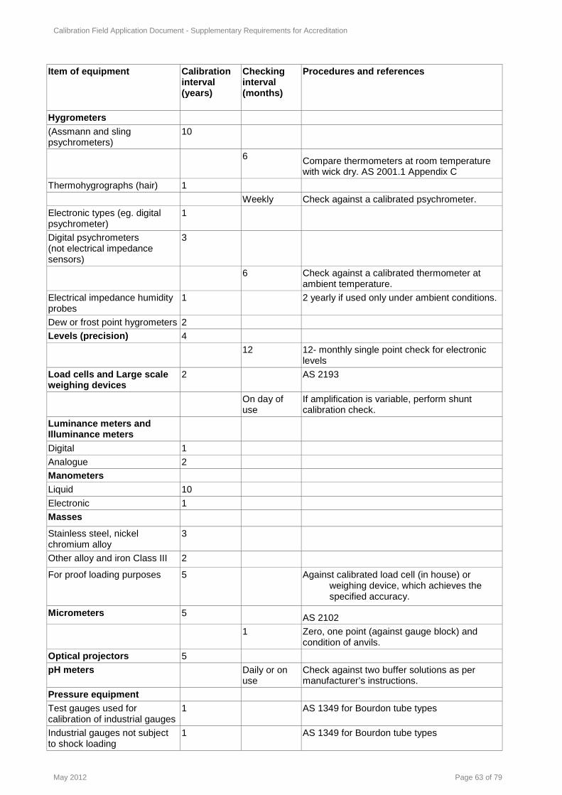
Calibration Field Application Document - Supplementary Requirements for Accreditation
May 2012 Page 63 of 79
Item of equipment Calibration interval (years)
Checking interval (months)
Procedures and references
Hygrometers
(Assmann and sling psychrometers)
10
6 Compare thermometers at room temperature with wick dry. AS 2001.1 Appendix C
Thermohygrographs (hair) 1
Weekly Check against a calibrated psychrometer.
Electronic types (eg. digital psychrometer)
1
Digital psychrometers (not electrical impedance sensors)
3
6 Check against a calibrated thermometer at ambient temperature.
Electrical impedance humidity probes
1 2 yearly if used only under ambient conditions.
Dew or frost point hygrometers 2
Levels (precision) 4
12 12- monthly single point check for electronic levels
Load cells and Large scale weighing devices
2 AS 2193
On day of use
If amplification is variable, perform shunt calibration check.
Luminance meters and Illuminance meters
Digital 1
Analogue 2
Manometers
Liquid 10
Electronic 1
Masses
Stainless steel, nickel chromium alloy
3
Other alloy and iron Class III 2
For proof loading purposes 5 Against calibrated load cell (in house) or weighing device, which achieves the specified accuracy.
Micrometers 5 AS 2102
1 Zero, one point (against gauge block) and condition of anvils.
Optical projectors 5
pH meters Daily or on use
Check against two buffer solutions as per manufacturer’s instructions.
Pressure equipment
Test gauges used for calibration of industrial gauges
1 AS 1349 for Bourdon tube types
Industrial gauges not subject to shock loading
1 AS 1349 for Bourdon tube types

Calibration Field Application Document - Supplementary Requirements for Accreditation
May 2012 Page 64 of 79
Item of equipment Calibration interval (years)
Checking interval (months)
Procedures and references
Industrial gauges subject to shock loading.
6 months AS 1349 for Bourdon tube types
Digital pressure gauges 1
Pressure transducers 1
Pressure transmitters 1
Calibrators 1
Radiation thermometers including Visible and Infrared Pyrometers
2 Initial test of target size dependence should be performed Initial calibration should include sufficient points to confirm linearity
12 Check at one point in range or at ice point
Disappearing filament pyrometers
3
Pyrgeometers 3
Sieves Initial Compliance certificate to AS 1152, BS 410.
12 More or less frequent checks may be required against a reference set or a suitable reference material.
Sound measuring devices, Including Sound level meters and Noise dosimeters
2
On use Check against acoustic calibrator or pistonphone
Acoustic calibrators including Pistonphones and sound sources
1 AS/IEC 60942
6 Intercompare
Spectrophotometers and Spectroradiometers
6 Wavelength accuracy, bandpass, absorbance, stray light error, linearity of response, repeatability and matching of cells.
On use A blank and at least 2 points on the calibration curve must be checked.
Tape measures, rules
Tape measures and retractable pocket rules
Initial AS 1290.4
24 to 60 Check at maximum length, depending on use and accuracy required.
Steel rules Initial BS 4372
6 1 point check within operating range.
Thermocouples
‘Base metal’ type, sheathed 2 For use up to 400°C. For use from 400°C to 1300 °C the same immersion depth must always be used (or a greater depth of immersion). Homogeneity must be assessed as part of their recalibration.
‘Base metal’ type, wire 2 For use up to 300o C. Replace if used above 300o C.
Stored reels 10 Reel of wire – 4 samples of wire from end points and middle of reel.

Calibration Field Application Document - Supplementary Requirements for Accreditation
May 2012 Page 65 of 79
Item of equipment Calibration interval (years)
Checking interval (months)
Procedures and references
‘Rare metal’ type 3 3 years or after 100 hours above 500o C whichever is sooner.
Thermocyclers 12 Check temperature uniformity across the block for a number of cycles, logging time spent at temperature using a measurement frequency of at least 2 Hz; check for excessive overshoot and undershoot (recovery rate) of temperature between temperature points. Check digital display accuracy as required.
Thermometers Liquid–in–glass
5
6 Check at ice point. NATA Technical Note 19 or against reference thermometer at 1 point in range
Resistance
-40°C to 250°C 5
6 Check at ice point.
<-40°C and >250°C 2
6 Check resistance at ice point.
Measuring instrument AC Bridge type, Reference and Working
5
Measuring instrument DC Bridge type
2
6 Check at ice point.
Digital indicating systems, with or without a temperature sensor, hand held or bench type, single and multichannel. (Includes temperature loggers)
2
6 Check against a reference device at the temperature of use. If used at more than one temperature, choose the most critical temperature. Check at ice point if the facility does not have a reference device. (For data loggers the reference device can not be another data logger of the same type).
Timing devices
Stop watches, clocks (mechanical and electrical devices)
6 Check using Telstra Clock or GPS signal
Torque wrench and transducers, Screwdrivers
1
6 In house cross check of overlapping ranges if possible.

Calibration Field Application Document - Supplementary Requirements for Accreditation
May 2012 Page 66 of 79
Item of equipment Calibration interval (years)
Checking interval (months)
Procedures and references
Velocity transducers 3
24 Check frequency response and sensitivity.
Volumetric glassware Initial (on commissioning and subject to nature of intended use)
AS 2162.1; BS 1797
SECTION 5: Classes of test
Accreditation in the Measurement Science and Technology (MST) field is described by classes and subclasses of test. Due to the large number of classes of test covered by MST, NATA has divided up the tests into class number 1 for calibrations and class number 3 for testing activities. It is recognised that in some cases an activity can be both a calibration and test and as such this division rule does not always apply. The classes of test shown in this section are a first order description of a facility’s accreditation. Most scopes of accreditation are described in more detail (refer to Expressing the scope of accreditation below). The scope of accreditation serves two functions. Firstly, it defines exactly which calibrations, measurement and tests the facility is accredited for. NATA endorsed test reports or calibration certificates can only be issued for the accredited tests. Secondly, it provides potential clients with information about available test or calibration services. Tests and calibrations performed in mobile laboratories, field laboratories or in-situ will also be described in the scope of accreditation. Where a facility wants to be accredited for tests and calibrations not covered by the existing classes of test, due to new technologies, changing regulatory requirements and client needs, the Accreditation Advisory Committee would consider creating new classes of test and developing new technical criteria for accreditation of such tests.
Expressing the scope of accreditation
For all scopes of accreditation, the description will be comprehensive and concise without omitting essential information. Under the classes/subclasses for calibration facilities, the following elements are covered:
• lists of parameters which can be measured; • measurement ranges for each parameter; • a statement of least uncertainty of measurement (this is usually at a 95% confidence level); • where appropriate, reference to a standard or in-house test method or to a specification; • for facilities performing AC electrical calibrations, the frequency or frequency range is listed for each
measurement type to help define the facility’s capability in the scope.
Classes of test
1.01 Limit gauges .01 Plain plug gauges .02 Plain ring gauges .03 Plain gap gauges .04 Taper plug gauges .05 Taper ring gauges .11 Parallel screw plug gauges .12 Parallel screw ring gauges .13 Adjustable thread calliper gauges for parallel threads .21 Taper screw plug gauges .22 Taper screw ring gauges

Calibration Field Application Document - Supplementary Requirements for Accreditation
May 2012 Page 67 of 79
.23 Adjustable thread calliper gauges for taper threads .31 Profile gauges .41 Position and receiver gauges .42 Micrometer setting gauges .61 Spline and serration gauges .99 Other limit gauges 1.02 Jigs, fixtures, cutting tools and components .01 Jigs and fixtures .02 Alignment of large scale assemblies .11 Cutting Tools .21 Components 1.03 Engineering metrology equipment .01 Surface plates .02 Toolmakers' flats .03 Straightedges .04 Squares .05 Angle plates .06 Bevel protractors .07 Engineers' parallels .08 Precision spirit levels .09 Micrometer water levels .10 Precision vee blocks .11 Optical flats .12 Optical parallels .13 Thread measuring accessories .14 Sine bars and sine tables .15 Dividing heads and tables .16 Eccentric mandrels .21 Micrometer heads .22 External micrometers .23 Internal micrometers .24 Depth Micrometers .25 Electronic indicators, dial gauges and test indicators .26 Bore gauges .27 Electronic and vernier callipers .28 Electronic and vernier height and depth gauges .29 Feeler gauges .30 Extensometers .31 Steel rules and measuring tapes .32 Micrometer setting gauges .99 Other measuring instruments and tools 1.04 Machine tools .01 Geometric features .02 Positioning accuracy .03 Performance tests 1.05 Surface topography .01 Surface texture .02 Roundness .03 Roundness standards 1.06 Gears, splines and serrations 1.07 Hardness of metal products 1.08 Length and angle standards .01 Angle gauges and precision polygons .02 External cylindrical standards .03 Internal cylindrical standards .04 Gauge blocks and accessories .05 Length bars and accessories

Calibration Field Application Document - Supplementary Requirements for Accreditation
May 2012 Page 68 of 79
.09 Precision circular scales .10 Precision graticules .11 Precision linear scales .12 Surface finish reference standards .13 Screw pitch reference standards .14 Spherical standards .15 Laser length standards .16 Calibration gauges for coordinate measuring machines .17 Area standards .18 Step and check gauges .99 Other length and angle standards 1.09 Precision instruments .01 Auto collimators .02 Theodolites .03 Alignment telescopes .04 Optical plumb lines .05 Optical levels .06 Photogrammetric cameras .07 Laser alignment and levelling equipment .08 Laser length interferometers .09 Wavemeters .21 Electronic levels .26 Engineers' comparators .31 Height setting micrometers .32 Length measuring machines .33 Coordinate length measuring machines .34 Screw diameter measuring machines .35 Screw pitch measuring machines .36 Gear and hob measuring equipment .37 Precision projection apparatus .38 Dial gauge calibrators .39 Extensometer calibrators 1.10 Survey and alignment equipment .01 Theodolites .02 Optical plumb lines .03 Optical levels .04 Laser alignment and levelling equipment .05 Survey staffs .06 Survey tapes .07 Tape testing benches .08 Electronic distance measuring equipment .09 Baselines .10 Position 1.11 Masses .01 Mass standards .02 Industrial mass standards .03 Determination of mass .04 Determination of mass for use with pressure calibrators 1.12 Weighing devices .01 Precision laboratory balances .02 Industrial balances .03 Industrial weighing appliances .04 Hopper Weighing Systems 1.13 Volumetric equipment .01 Volumetric glassware .02 Special laboratory volumetric apparatus .03 Industrial volumetric proving measures .11 Standard measures .12 Pipe provers

Calibration Field Application Document - Supplementary Requirements for Accreditation
May 2012 Page 69 of 79
.13 Industrial storage tanks .14 Road and rail tankers .15 Piston Operated Volumetric Apparatus, pipettes (POVAS) .99 Other equipment 1.14 Density
.01 Density of solids
.02 Density of liquids
.03 Density of gases
1.15 Hydrometers .01 Density hydrometers .02 Alcoholmeters .03 Brix hydrometers .04 LPG hydrometers .99 Other hydrometers
1.16 Densitometers .01 Liquid densitometers .02 Gas densitometers
1.17 Flow measuring devices .01 Anemometers .02 Sonic nozzles .03 Orifice meters .04 Gas meters .05 Flow hoods .06 Wind direction devices .11 Liquid meters .21 Current meters .22 Open channel water meters .23 Weir type structures .99 Other devices
1.18 Oil and gas measurement systems 1.19 Barometers
.01 Aneroid barometers
.02 Barographs
.03 Mercury barometers
.04 Gauge barometers
.11 Altimeters
.99 Other barometers
1.20 Pressure and vacuum measuring devices .01 Pressure gauges .02 Vacuum gauges (bourdon tube) .11 Pressure transducers .12 Pressure calibrators .13 Pressure recorders .21 Mercury manometers .22 Other liquid manometers .23 Digital manometers .31 Pressure control devices
1.21 Pressure balances .01 Air operated piston gauges .02 Oil operated piston gauges .04 Determination of mass for dead weight testers

Calibration Field Application Document - Supplementary Requirements for Accreditation
May 2012 Page 70 of 79
1.22 Pressure tests .11 Hydrostatic pressure tests .12 Pulsating pressure tests .13 Head loss tests .14 Pressure control devices
1.23 Force measuring devices .01 Calibrating devices .02 Elastic force measuring devices .04 Load cells .05 Force gauges .99 Other devices
1.24 Speed measuring devices .01 Doppler radar equipment .02 Laser equipment .05 Fixed detector installation .11 Speedometers .99 Other devices
1.25 Torque measuring devices .01 Torque wrenches .02 Torque transducers .03 Torque multiplying gearboxes .04 Torque calibrating devices
1.26 Testing machines .01 Tension and universal machines in tension .02 Compression and universal machines in compression .11 Vickers hardness machines .12 Rockwell hardness machines .13 Brinell hardness machines .14 Rockwell superficial hardness machines .15 Vickers low-load hardness machines (HV 0.2 to HV 5) .16 Vickers micro-hardness machines (less than HV 0.2) .21 Izod impact machines .22 Charpy impact machines .25 Resilience testing machines .31 Deadweight rubber hardness testers .32 Dead Weight micro-hardness rubber testers .33 Rubber hardness meters (durometers) .34 Plastics hardness testers .41 Torsion machines .42 Tension-torque machines .71 Road friction testers .99 Other testing machines 1.27 Ancillary mechanical testing equipment .01 Portable Brinell measuring microscopes .02 Indenters for hardness machines .11 Hardness blocks for metals testing .12 Hardness blocks for rubber and plastics testing .21 Thickness gauges for textiles, rubber and plastics .22 Specimen cutters for rubber and plastics .31 Paper products testing equipment .99 Other equipment 1.28 Ancillary testing equipment for construction materials .11 Test sieves .21 Ovens .25 Dial gauges and other displacement measuring devices .31 Vicat apparatus .35 Penetrometers and penetration cones

Calibration Field Application Document - Supplementary Requirements for Accreditation
May 2012 Page 71 of 79
.36 Penetration needles .41 Nuclear moisture/density gauges .42 Gyropac angle calibrator .99 Other equipment 1.29 Ancillary testing equipment for paints and petroleum products .11 Wet film thickness gauges .12 Fineness of grind gauges .13 Viscometers .14 Flow cups .15 Scratch needles .21 Ovens .83 Pensky-Martens apparatus .99 Other equipment 1.32 Resistors, resistance boxes and potential dividers .01 Precision resistors, resistance boxes and conductance boxes .02 Volt ratio boxes and potential dividers .03 DC shunts .04 AC shunts .99 Other tests 1.33 Capacitors .01 Precision capacitors .02 Capacitance attenuators .03 Capacitance potential dividers 1.34 Magnetic Instruments and Equipment .02 Magnets, solenoids and Helmholtz coils .03 Magnetic permeameters .04 Magnetic frames and squares .05 Fluxmeters .06 Magnetometers and search coils .07 Hibbert magnetic standards and other flux linkage generators .08 Flux density meters 1.35 Inductors and Instrument Transformers .01 Inductors, self and mutual .02 Ratio transformers .03 Current Transformers .04 Voltage Transformers 1.36 Voltage standards .01 Standard cells .11 Electronic e.m.f. reference devices 1.37 Precision transfer instruments .01 A.C./D.C. transfer instruments 1.38 Instrument calibrators .01 D.C. voltage .02 A.C. voltage .11 D.C. current .12 A.C. current .51 Resistance 1.39 Indicating and recording instruments .01 D.C. voltmeters .02 A.C. voltmeters .03 D.C. ammeters .04 A.C. ammeters

Calibration Field Application Document - Supplementary Requirements for Accreditation
May 2012 Page 72 of 79
.05 Wattmeters .06 Varmeters .07 Phase angle indicators .08 Power factor meters .09 Ohmmeters .10 LCR meters .11 Galvanometers and null detectors .21 Electricity meters .81 Graphic recording instruments .82 Digital storage recorders .83 Instrumentation tape recorders .84 Electric field strength meters 1.40 Bridges, potentiometers, test sets .01 D.C. bridges .02 D.C. potentiometers .11 A.C. bridges .12 A.C. potentiometers .21 Ratiometers .31 Current transformer testing sets .32 Voltage transformer testing sets .33 Partial discharge test equipment .41 High voltage test sets 1.41 Frequency and time measuring instruments and standards .01 Frequency meters .02 Wavemeters .11 Counters .12 Time interval meters .13 Clocks and watches .14 Stroboscopes .15 Tachometers .21 Frequency standards .31 Calibration of frequency .32 Time interval calibration .33 Coordinated Universal Time (UTC) 1.42 Frequency analysers and waveform measuring instruments .01 Frequency characteristics .02 Input characteristics .03 Timing characteristics .04 Distortion .99 Other characteristics 1.43 Signal sources .01 Frequency characteristics .02 Output characteristics .03 Modulation characteristics .04 Sweep characteristics .99 Other characteristics 1.46 Power rectifiers .01 Rotary, vibratory and other mechanical types .02 Silicon controlled rectifiers and allied control devices .03 Vacuum tube rectifiers .04 Semiconductor rectifiers 1.47 Communications equipment .01 Line transmission measuring equipment .02 Radio transmission measuring equipment .03 Field intensity measuring equipment .04 Electrical noise and interference measuring equipment .05 Impedance and reflection measuring equipment

Calibration Field Application Document - Supplementary Requirements for Accreditation
May 2012 Page 73 of 79
.06 Spectrum analysis measuring equipment .07 Data transmission equipment .08 Power measuring equipment .09 Attenuators and amplifiers .11 Waveguide and coaxial components .12 Communications systems .13 Data acquisitions systems .14 Processor controlled systems .99 Other equipment 1.51 Electronic equipment .01 High voltage impulse and disturbance tests .10 Transducer indicators and calibrators .11 Charge amplifiers .30 Miscellaneous equipment and tests 1.52 Calibration of electromagnetic field strength transducers and indicators .01 Antennas .02 Field strength probes .10 Electric field strength .11 Power density 1.54 EMC test equipment
.01 Pulse characteristics of Electrostatic Discharge (ESD) generators.
.02 Pulse characteristics of Electrical Fast Transients (EFT) and Surge Generators
.03 Voltage division factor, impedance and isolation characteristics of Artificial Mains Networks (AMN)
.04 Insertion loss and common mode impedance characteristics of Coupling/Decoupling networks (CDN)
1.55 Calibration of polarimetric instruments .01 Polarimeters .02 Saccharimeters .03 Quartz control plates 1.56 Refractive Index .01 Calibration of abbe refractometers 1.57 Radiant flux (radiant power) .01 Radiant power of laser line sources .02 Radiant power of incoherent line sources 1.58 Calibration of irradiance measuring instruments .01 Pyrheliometers .02 Pyranometers .03 Ultraviolet pyranometers .04 Pyrradiometers .05 Albedometers .06 Pyro-albedometers .07 Calibration of ultraviolet radiometers .08 Calibration of infrared radiometers .09 Calibration of ultraviolet dosimeters .10 Pyrgeometers 1.59 Broad-band irradiance .01 Measurement of ultraviolet irradiance .02 Measurement of infrared irradiance 1.61 Luminous intensity .01 Incandescent lamps .02 Other sources

Calibration Field Application Document - Supplementary Requirements for Accreditation
May 2012 Page 74 of 79
1.62 Luminous flux .01 Incandescent lamps .02 Other sources 1.63 Luminance .01 Measurement of luminance .02 Calibration of luminance meters 1.64 Illuminance .01 Measurement of illuminance .02 Calibration of illuminance meters 1.65 Broad-band visible light measurements .01 Transmittance .02 Reflectance .03 Luminance factor .04 Chromaticity .05 Correlated colour temperature .06 Haze .07 Gloss .08 Calibration of transmittance densitometers .09 Calibration of reflectance densitometers .10 Calibration of incident light tricolorimeters .11 Calibration of reflectance tricolorimeters .12 Calibration of colour temperature meters .13 Calibration of hazemeters .14 Calibration of gloss meters 1.66 Retroreflection .01 Reflex reflectivity .02 Chromaticity 1.67 Luminance factor .01 Broad-band measurements 1.68 Spectral measurements of light sources .01 Spectral radiance .02 Spectral irradiance .03 Chromaticity .04 Correlated colour temperature .05 Distribution temperature .06 Calibration of spectroradiometers 1.69 Spectrophotometry .01 Spectral transmittance .02 Spectral reflectance .03 Chromaticity .04 Calibration of spectrophotometers 1.70 Optical and radiation detectors .01 Broad-band responsivity .02 Response linearity .03 Spectral responsivity .04 Cosine correction .05 Wavelength .06 Spectrum 1.72 Ionising radiation .01 Measurement of alpha, beta, gamma, neutron radiations .02 Calibration of ionising radiation survey instruments .03 Measurement of X-rays .04 Calibration of dosimeters
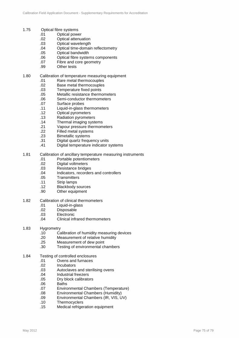
Calibration Field Application Document - Supplementary Requirements for Accreditation
May 2012 Page 75 of 79
1.75 Optical fibre systems .01 Optical power .02 Optical attenuation .03 Optical wavelength .04 Optical time-domain reflectometry .05 Optical bandwidth .06 Optical fibre systems components .07 Fibre and core geometry .99 Other tests 1.80 Calibration of temperature measuring equipment .01 Rare metal thermocouples .02 Base metal thermocouples .03 Temperature fixed points .05 Metallic resistance thermometers .06 Semi-conductor thermometers .07 Surface probes .11 Liquid-in-glass thermometers .12 Optical pyrometers .13 Radiation pyrometers .14 Thermal imaging systems .21 Vapour pressure thermometers .22 Filled metal systems .23 Bimetallic systems .31 Digital quartz frequency units .41 Digital temperature indicator systems 1.81 Calibration of ancillary temperature measuring instruments .01 Portable potentiometers .02 Digital voltmeters .03 Resistance bridges .04 Indicators, recorders and controllers .05 Transmitters .11 Strip lamps .12 Blackbody sources .90 Other equipment 1.82 Calibration of clinical thermometers .01 Liquid-in-glass .02 Disposable .03 Electronic .04 Clinical infrared thermometers 1.83 Hygrometry .10 Calibration of humidity measuring devices .20 Measurement of relative humidity .25 Measurement of dew point .30 Testing of environmental chambers 1.84 Testing of controlled enclosures .01 Ovens and furnaces .02 Incubators .03 Autoclaves and sterilising ovens .04 Industrial freezers .05 Dry block calibrators .06 Baths .07 Environmental Chambers (Temperature) .08 Environmental Chambers (Humidity) .09 Environmental Chambers (IR, VIS, UV) .10 Thermocyclers .15 Medical refrigeration equipment

Calibration Field Application Document - Supplementary Requirements for Accreditation
May 2012 Page 76 of 79
1.90 Acoustic measuring and calibration equipment .01 Microphones .02 Sound level meters .03 Sound analysers .04 Band pass filters .05 Acoustic calibrators .06 Reference sound sources .07 Sound level recording systems .08 Signal recorders .09 Audiometers .10 Dose meters for sound .99 Other acoustic measuring equipment 1.91 Vibration measuring and calibrating equipment .01 Vibration transducers .02 Vibration measuring systems .03 Vibration analysers .04 Vibration filters .05 Vibration recording systems .06 Vibration calibrators .99 Other vibration measuring equipment 1.92 Dynamic balancing machines 1.99 Approved Signatories
SECTION 6: References
This section lists publications referenced in this document. The year of publication is not included as it is expected that only current versions of the references shall be used.
NATA Technical Circulars
NATA Technical Circular 7 Proficiency Testing policy for Calibration Activities
Other references
Assessment of Uncertainties of Measurement for calibration and testing laboratories, R R Cook, NATA
ISO/IEC Guide 99 (2007) International vocabulary of metrology – Basic and general concepts and associated terms (VIM)
The Calibration of Weights and Balances, E C Morris and K M K Fen, National Measurement Institute, Australia NMI Monograph 4.
ISO Guide to the Expression of Uncertainty in Measurement
Guidance documents covering the implementation of specific accreditation requirements are also available from the ILAC (www.ilac.org) and APLAC (www.aplac.org) websites.
National Measurement Regulations 1999
NMI V1 Uniform Test Procedures for the Verification, Certification and In-service Inspection of Non-automatic Weighing Instruments
Thermocouples in Temperature Measurement – RE Bentley, NMI Monograph 5
Platinum Resistance Thermometry - JJ Connolly NMI Monograph 11
Liquid-in-glass Thermometry – C Horrigan and RE Bentley, NMI Monograph 9
Radiation Thermometry – MJ Ballico, NMI Monograph 12
Introduction to Radiometry – EG Atkinson, MJ Ballico, JL Gardner, PB Lukins, ED Thorvaldson, FJ Wilkinson, NMI Monograph 10.

Calibration Field Application Document - Supplementary Requirements for Accreditation
May 2012 Page 77 of 79
Uncertainty in Measurement: The ISO Guide - RE Bentley, NMI Monograph l.
Grum, F. and Becherer, R.J. (1979) Optical Radiation Measurements, Vol. 1 Radiometry. Published by Academic Press, New York.
Grum, F. and Becherer, R.J. (1980) Optical Radiation Measurements, Vol. 2 Color Measurement. Published by Academic Press, New York.
Grum, F. and Becherer, R.J. (1982) Optical Radiation Measurements, Vol. 3 Measurement of Luminescence. Published by Academic Press, New York.
Mielenz, K D, Volume 3 - Measurement of Luminescence
Bartleson, James, Grum & Franc, Volume 4 - Visual Measurement
Budde, W, Volume 5 - Physical Detectors of Optical Radiation
CIE (Aust) Publications - No.1 up to No.81 on Photometry and Radiometry (Obtainable from Australian National Committee on Illumination)
Eckerle, Hsia, Mielenz & Weidner, Regular Spectral Transmittance, NBS Measurement Services
Hsia & Weidner, Spectral Reflectance, NBS Measurement Services
Booker & McSparron, Photometric Calibrations, NBS Measurement Services
Walker, Saunders & Hattenburg, Spectral Radiance Calibrations, NBS Measurement Services
Walker, Saunders & Jackson, Spectral Irradiance Calibrations, NBS Measurement Services
Cornelius, W A, Non-ionising Radiation Measurements and Protection, Australian Radiation Laboratory
Sliney, D, & Wolbarsh, M, Safety with Lasers and Other Optical Sources, Plenum 1980
Fox, N P, & Nettleton, D H, New Developments and Applications in Optical Radiometry
Dain, S J, The Measurement of Light and Colour, School of Optometry, University of New South Wales (1992)
CSIRO National Measurement Laboratory (1987) – Optical Radiometry Course
NHMRC Radiation Health Series No 24 Code of practice for the design and safe operation of non-medical irradiation facilities.
NSW/EPA Guideline-Monitoring devices (March 1997).
NSW Radiation Control Act (1990) No 13.
NSW Radiation Control Act (1990) Regulation No 434.
WA Radiation Safety Regulations (1983) reprinted 1995.
NCRP Report No 112 (1991). Calibration of survey instruments used in Radiation protection for the assessment of ionizing radiation fields and radioactive surface contamination.
IAEA Technical Reports Series No 133 (1971). Handbook on calibration of radiation protection monitoring instruments.
IAEA Technical Reports Series No 285 (1988). Guidelines on calibration of neutron measuring devices.
IAEA Technical Reports Series No 374 Calibration of dosimeters used in radiotherapy
Kathren, R.L. Health Physics 29, 143-153 (1975). Standard sources for health physics instrument calibration.
BIPM/IEC/ISO/OIML. International Vocabulary of Basic and General Terms in Metrology.
NCRP Report 112 (1991). Calibration of survey instruments used in radiation protection for the assessment of ionising radiation fields and radioactive surface contamination.
ICRU Report 39 (1985). Determination of dose equivalent resulting from external radiation sources.
ICRU Report 43 (1988). Determination of dose equivalent resulting from external radiation sources - Part 2.
ICRU Report 47 (1992). Measurement of dose equivalent from external photon and electron radiation.
ICRU Report 51 (1993). Quantities and units in radiation protection dosimetry.
ICRP74 (1996). Conversion coefficients for use in radiological protection against external radiation.
ILAC Policy for Uncertainty in Calibration ILAC-P14:12/2010

Calibration Field Application Document - Supplementary Requirements for Accreditation
May 2012 Page 78 of 79
Physical and Dimensional Metrology Standards
AS 1004 Surface plates for metrology Part 1: Cast iron, Part 2: Granite
AS 1349 Bourdon tube pressure and vacuum gauges
AS 1290 Linear measuring instruments used in construction
Part 1 - General Requirements
Part 4 – retractable steel pocket rules
Part 5 - Coated and etched steel measuring tapes
AS 1457 Geometrical Product specifications (GPS) - Length standards - Gauge blocks
AS 1545 Methods for the calibration and grading of extensometers
AS 1984 Vernier Callipers
AS 2026 Laboratory glassware - Density hydrometers
AS 2102 Micrometer Callipers for external measurement
AS 2103 Dial Gauges and Dial Test Indicators
AS 2162.1 Verification and use of volumetric apparatus – General, volumetric glassware
AS 2162.2 Guide to the use of piston-operated volumetric apparatus
AS 2193 Calibration and classification of force-measuring systems
AS 2328 Micrometer heads - Metric series
AS 3807 Vocabulary of basic and general terms in metrology
ASME B89.7.3.1 Guidelines for decision rules: Considering measurement uncertainty in determining conformance to specifications
BS 4372 Specification for engineers steel measuring rules
ISO 14253.1/
AS 4826.1 Geometrical Product Specifications (GPS) - Inspection by measurement of workpieces and measuring equipment - Part 1: Decision rules for providing conformance or non-conformance with specifications
Acoustic
AS 1055.1 Acoustics - Description and measurement of environmental noise
AS 1259.1 Sound level meters: non-integrating
AS 1259.2 Sound level meters: integrating - averaging
AS/NZS 2399 Acoustics – Specifications for personal sound exposure meters
IEC 61094-5 Pressure Microphone Calibration
ISO 3740 Sound power levels of noise sources
AS/IEC 61672 Electroacoustics - Sound Level Meters
Part 1: Specifications
Part 2: Pattern evaluation tests
Part 3: Periodic tests (Not yet released as Australian Standard at time of print)
AS/IEC 60942 Electroacoustics - Sound Calibrators
AS/IEC 60645.1 Electroacoustics – Audiological equipment
Part 1: Pure-tone audiometers
ISO 3741:1999 Acoustics -- Determination of sound power levels of noise sources using sound pressure -- Precision methods for reverberation rooms.
ISO 3745:2003 Acoustics -- Determination of sound power levels of noise sources using sound pressure -- Precision methods for anechoic and hemi-anechoic rooms.
Vibration measurement
ISO/CD 16063-21 Vibration and Shock Transducer Calibration

Calibration Field Application Document - Supplementary Requirements for Accreditation
May 2012 Page 79 of 79
Ionising Radiation and Radiation Contamination Stan dards
AS 2243.4 Safety in Laboratories - ionising radiations
ARL/TR088 Calibration facility for radiation protection monitors in Australia
NBS 250-16 Calibration of X-ray and gamma ray measuring instruments
OIML D 21 Secondary standard dosimetry laboratories for the calibration of dosimeters used in radiotherapy
ISO 4037 X- and gamma reference radiations for calibrating dosimeters and dose ratemeters and for determining their response as a function of beta radiation energy
ISO 6980 Reference beta radiations for calibrating dosimeters and dose ratemeters and for determining their response as a function of beta radiation energy
ISO 7503-1 Evaluation of surface contamination - Part 1: Beta emitters (maximum energy greater than 0.15 MeV)
ISO 8529 Neutron reference sources for calibrating neutron-measuring devices used for radiation protection purposes and for determining their response as a function of neutron energy
ISO 8769 Reference sources for the calibration of surface contamination monitors. Beta emitters (maximum beta energy greater than 0.15 MeV) and alpha emitters
ISO 4071 Exposure Meters and Dosimeters – General methods for Testing
ISO 8963 Dosimetry of X- and Gamma Reference Radiations for Radiation Protection over the Energy Range from 8 keV to 1.3 MeV
ANSI N13.11 Criteria for Testing Personnel Dosemetry Performance
IEC-1066 Thermoluminescent Systems for Personnel and Environmental Monitoring
Temperature measurement
AS 2853 Enclosures – Temperature Controlled-Performance testing and grading
AS/NZS 4859 Materials for the thermal insulation of buildings – General criteria and technical provisions


