CALEC ST Innovative solutions in energy measurementGlythermin P44 GLYTHP44 40% - 80% - 100°C 1)...
13
VD 3-181 e 04.2004 Applications The CALEC ® ST is an energy totalizer with communication capabilities for critical measuring tasks such as those for: • Heating plants • Climatic ceilings and thermally-activated building components and those that can be integrated into heating and cooling systems • Solar energy plants in apartment blocks and other buildings • Communication with building management systems Your benefits • Heat and cold measurement • For cold and solar thermal plants • For monitoring operations • With expansion modules • Optimum LON integration • Simultaneous read-out from the network • Cost-savings with subsequent verification CALEC ® ST Innovative solutions in energy measurement Features • New: For combined heating/cooling systems • New: For glycol-based heat carriers • New: Memory for 60 measurement sets (logger) • Optional pulsed inputs/outputs • Battery or mains version • Optional LON interface, FTT-10A, certified to LONMARK ® 3.2 • Freeze function • Separate, verified plug-in totalizer module
Transcript of CALEC ST Innovative solutions in energy measurementGlythermin P44 GLYTHP44 40% - 80% - 100°C 1)...

VD 3
-181
e 0
4.20
04
ApplicationsThe CALEC® ST is an energy totalizer with communication capabilities for critical measuring tasks such as those for:
• Heating plants
• Climatic ceilings and thermally-activated building components and those that can be integrated into heating and cooling
systems
• Solar energy plants in apartment blocks and other buildings
• Communication with building management systems
Your benefits• Heat and cold measurement
• For cold and solar thermal plants
• For monitoring operations
• With expansion modules
• Optimum LON integration
• Simultaneous read-out from the network
• Cost-savings with subsequent verification
CALEC® STInnovative solutions in energymeasurement
Features• New: For combined heating/cooling systems
• New: For glycol-based heat carriers
• New: Memory for 60 measurement sets (logger)
• Optional pulsed inputs/outputs
• Battery or mains version
• Optional LON interface, FTT-10A, certified to
LONMARK® 3.2
• Freeze function
• Separate, verified plug-in totalizer module
2
Application
The CALEC® ST is available as a remote (split) version for energy measuring points fitted with passive pulsed volumetric flowmeters and2- or 4-wire Pt100 or Pt500 temperature sensors. The CALEC® ST is usually operated with the following flowmeters:
• multijet flowmeters for the range Qp 0,6 - 10 m3/h• Woltman flowmeters for the range Qp 15 - 400 m3/h• static flowmeters up to Qp 400 m3/h
Select from our extensive range of flowmeters or simply contact us for more details.
The CALEC® ST Flow is a flow totalizer with a similar function but without temperature measurement.
Compulsory calibration and design approvalEnergy measuring points are subject to verification in most countries and the equipment used must have design approval. At present, theCALEC® ST is approved to EN 1434-1 for use in those countries shown in the approvals section (page 11).
Heat meters for commercial use must be verified again before their present certificate expires. The operator is responsible for this subse-quent verification. Verification includes all components of a composite heat meter (sensors, flowmeter, totalizer).At present, design approval may only be given for water as the heat carrier medium and for simply heat or cooling operations.Because of administrative reasons design approval cannot be given for some functions including
• operation with glycol-based heat carriers• combined heating/cooling operations• low flow cut-off,
that means that these functions may not be used in custody transfer.
Standard applications and measuring principlehe following individual verified elements are required for a composite heat meter:
• 1 pair of temperature sensors• 1 flowmeter with pulse signal transmitter• 1 transformer (totalizer).

3
The thermal power P released in a piping network is derived from the measuring of flow pipe temperature, return pipe temperature andmass flow of the carrier medium.
P = specific heat (Tm, medium) * density (Tm, medium) * (Thot - Tcold)
Thot : higher temperature, with heated flow temperatureTcold : lower temperature, with heated return temperatureTm: mean temperature = (Thot – Tcold)/2
Energy can be calculated with respect to power. The equation shows that, for energy measurement, the specific heat and the density ofthe heat carrier must be calculated as a function of the temperature in the totalizer. The factors on which measurement accuracy dependinclude:
• the static accuracy and stability of temperature measurement• the totalizer period for temperature measurement and the flowrate for determining dynamic processes
CALEC® ST is especially equipped for demanding measurement duties with its
• high-resolution and long-term stable 16 bit AD converter for temperature measurement and an integrated self-calibration and filter func-tion
• rapid totalizer clock (mains version 1 s)• optional high-resolution mechanical or electrical flow transmitter with a pulse frequency up to 200 Hz (mains version).
Energy measurement in heating/cooling plantsThe optional "bi-directional energy measurement" (BDE) enables energy released to also be measured in two-pipe networks in combinedheating/cooling operations. The hot and cold measured values are determined in separate registers so that they can be invoiced at the ap-propriate rates.
Cold plantsBelow freezing temperatures in cold plants require the use of antifreeze. Standard heat meters are thus faced with many insuperable pro-blems such as those examined in detail in the PTB report PTB-ThEx 24 dated June 2002.
With its "glycol based heat carrier" (GLY) option, CALEC® ST can therefore also carry out precision measurement in such cases. This is be-cause, with its sliding values of temperature-dependent density and heat capacity, the energy and mass can be calculated for every tem-perature. CALEC® ST calculates the exact values with polynomials of the seven most common heat carriers as a function of concentrationand temperature (as shown in the table below).
8
6
4
2
0
-2
-4
-6
-8
Heating
Cooling
1 2 3 4
ener
gy c
onsu
mpt
ion
5 6 7 8 9 10 11 12
month
E+, V+
E-, V-

4
Only the type of heat carrier and its concentration need to be defined when commissioning (as shown in the table below):
1) Minimum temperature depends on concentration –40…0 °C2) Based on ethylene glycol 3) Based on propylene glycol 4) The names are registered trade marks of the companies mentioned.
The following graphs give examples showing that the temperature dependence of specific heats and densities significantly affects the cal-culation.
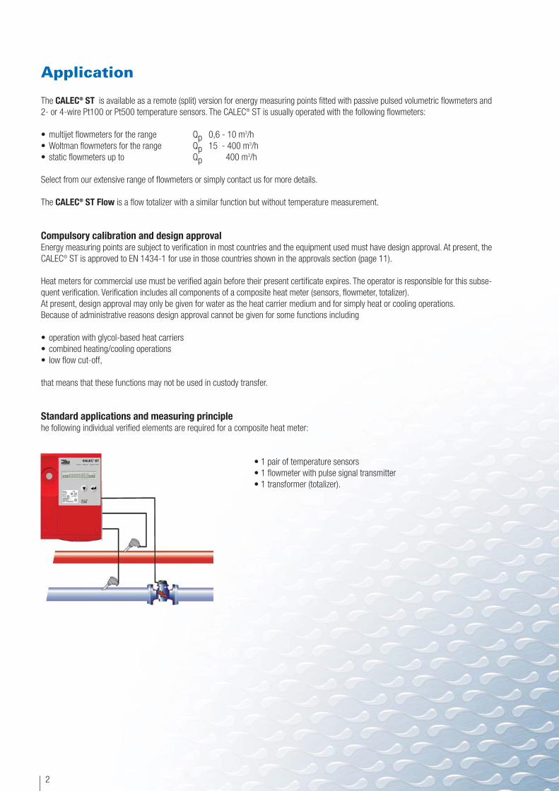
Solar plantsTemperature range and the heat carrier used greatly affect energy measurement in solar plants.
AWith its optional "glycol-based heat carrier"GLY, CALEC® ST is the ideal solution for this appli-cation (see also the section on cold plants).
Medium 4) Display Concentration Temperature Manufacturer Type Application/remarksrange
Antifrogen N AntifroN 20% - 60% - 120°C 1) Clariant E 2) Complies with DIN 4757-1; poison type 4For cooling, solar, heating and ther-mal pump plantsLow viscosity requires smaller pumping capacities
Antifrogen L AntifroL 20% - 60% - 120°C 1) Clariant P 3) Completely safe, Pharmaceuticals,foodstuffs
Tyfocor Tyfocor 20% - 60% - 120°C 1) Tyfocor E See Type ETyfocor-L TyfocorL 20% - 60% - 120°C 1) Chemie P See Type PDowCal 10 DOUCAL10 30% - 70% - 120°C 1) Dow E See Type EDowCal 20 DOUCAL20 30% - 70% - 120°C 1) Dow E See Type EGlythermin P44 GLYTHP44 40% - 80% - 100°C 1) BASF P FDA approval in USA, corrosion-
protection less effectiveFor pharmaceuticals and foodstuffsplants
Solar panel
Pump
Boiler
Pump
Solar tank
Customer
coldt
hott
Temperature (°C)
(kJ/
kg.K
)
Temperature (°C)
Dens
ity (g
/cm
3)
DOWCAL is a registered trade mark of Dow Chemical

5
Communication
M-BusThe outstanding characteristics of the M-Bus and its standardization to EN 1434-3 ensure:
• simple installation• cost savings• compatibility to multinational suppliers
These make it the ideal choice for building management systems eve-rywhere.
The CALEC® ST can therefore be equipped with up to 2 M-Bus interfaces.Not only standard data, such as meter readings and actual measurement values are read, but also additional data such as billing dates andvalues in the memory can be called up via M Bus interfaces.
The primary address and baud rate can be set using the keys on the CALEC® ST so that start-up can be done without a PC.
The Freeze function (see also page 7) also ensures values can be simultaneously read in extensive M-Bus networks subject to long timedelays.
The M bus is a single master bus and only a slave bus can therefore communicate with it. If another device for remote reading is to trans-mit data to another M-Bus master used in the building management system, then this can only be done with devices fitted with two M-Businterfaces. For this, the CALEC® ST can be fitted with a second M-Bus interface.
The LON interfaceUnlike M-Bus systems, a Local Operating Network enables the functions of the building management system to be integrated with the me-ter readings into a single system. The Local Operating Network (LON) is a multimaster system with intelligent nodes which can use diffe-rent signal carriers. A LON interface card (FTT-10 A) is available for the CALEC® ST to transmit over two wires (twisted pair). One outstan-ding feature of LON technology is its interoperability, which ensures that the lifetime of the building management system exceeds that ofany of its individual components. The CALEC® ST is the first energy totalizer to be certified according to LONMARK® 3.2 so that interopera-bility is no longer an empty promise. This means smooth integration into a LON along with savings of time and money. The commissioningprocedure also means that there are no nasty surprises or uncertainties with billing. The LonMark certificate also ensures:
• data objects of the network node are in the object library of integration tools (e.g. LonMaker) and can easily be used• signals and interfaces are fully defined in the External Interface File (XIF) so that the system function can be programmed offline, (i.e. wi-
thout peripherals).• CALEC® ST has the total functionality of a LON node, including diagnosis and installation help functions such as the service LED and ser-
vice key.• allocating nodes to data points can be carried out using the identification number of the neuron chip: the NeuronID. An adhesive label
with the NeuronID as a bar code is enclosed with the device. Installation personnel can stick the label onto the appropriate area of the plan after assembly. This ensures that the integration specialist can record this and assign data at the work desk using a bar code reader.
The NOWA interfaceThe CALEC® ST can be checked on neutral NOWA test beds using a suitable software interface.
Limit signal,Alarm signal,Power,Flowrate
M-Bus Masterfor BMS
M-Bus Masterfor remote reading
M-Bus #1
M-Bus #2
6
Digital input and outputs
The CALEC® ST can be equipped with two digital signal interfaces that can be switched to inputs or outputs. These signals can be used toprovide counting pulses or to transmit limit violations or alarms to the building management system.
Limit signalsThe digital output signals can be used for transmitting a limit value monitoring signal. The following parameters can thus be monitored:
1. Single limit monitoring (Limit 1) The output signal changes once a value moves outside a preset maximum or minimum level; hysteresis (0-10 %) and action can be se-lected as required. For control purposes, the length of time of the violation the limit value is totalized in the device (display: Cnt for Coun-ter).
2. Double limit monitoring (Limit 2)The operation is identical to Limit 1 and is activated once a value moves outside a preset maximum and minimum.
AlarmThe microprocessor monitors the temperature sensors and internal functions as well as indicates errors, which are shown on the display.This information can also be transmitted as an alarm via a digital output.
Additional functions
Billing datesWith two freely-programmable billing dates, meter readings can be accurately stored between the two dates and read out at any time, e.g.on 31 March and 30 September.
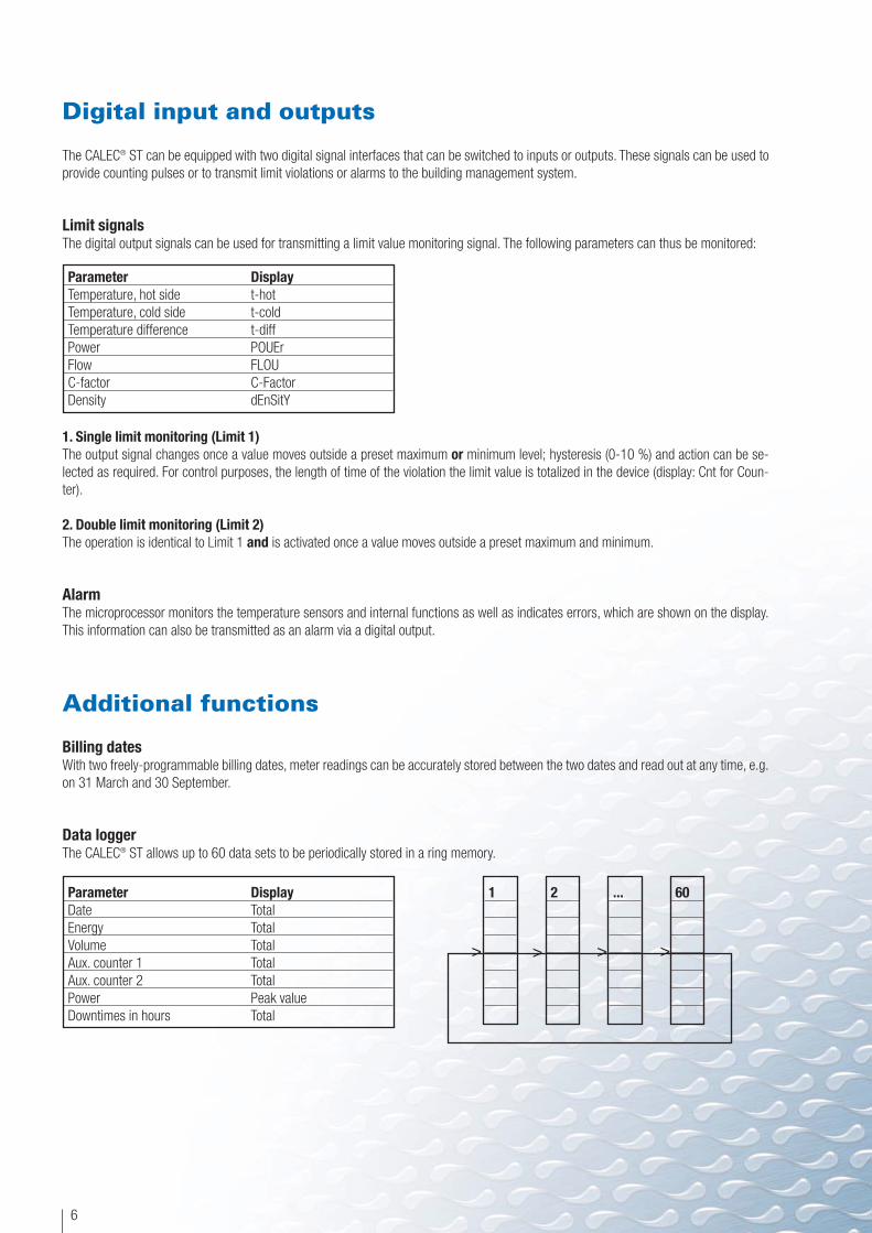
Data loggerThe CALEC® ST allows up to 60 data sets to be periodically stored in a ring memory.
Parameter DisplayTemperature, hot side t-hotTemperature, cold side t-coldTemperature difference t-diffPower POUErFlow FLOUC-factor C-FactorDensity dEnSitY
Parameter DisplayDate TotalEnergy TotalVolume TotalAux. counter 1 TotalAux. counter 2 TotalPower Peak valueDowntimes in hours Total
1 60...2
> >>>

7
Simultaneous readings with the M-Bus and LON (Freeze)Because of the long delay times that can occur with communication, it may not be possible to have simultaneous read-out of several me-ters using a meter bus system.
The Freeze function of the CALEC® ST is the ideal solution for this. Using a broadcast command, all devices simultaneously store all theircurrent measurements. These can then be read out one after the other. This Freeze function is available for both the M-Bus and the LON.
Low flow cut offWhen first operated, the meter is set up to carry out energy calculations as soon as there is a temperature difference of > 0 (for heat me-asurement) or < 0 (for cold measurement). For example, if large amounts of the heat carrier medium are flowing where there is a very lowtemperature difference, the error resulting from temperature measurement can be quite significant. To prevent this, the CALEC® ST can ac-tivate the low flow cut off function so that the energy is only determined once a defined temperature difference is detected (with no verifi-ed measuring points only).
Operation
All settings on the CALEC® ST can be made on the instrument itself in a logical sequence without the need of peripheral equipment.
Multifunction display
Meter readings with up to 8 numerical characters, symbols and short texts can be shown on the multifunction display as an interactive process guide.
The displays can be selected by pressing two keys when the housing is closed and the device is in operation:
Operating keys
The service key is located under the cover and protected by a leaded seal. Pressing this key enables additional service information to be dis-played and settings made:
Service key
Flow indication
Memory
Alarm indication
Places after the decimal point
8 character decimal field
Edit mode
Service mode
User mode
UnitsIdentification

The following diagram shows all the necessary information required in the main flow loop with short texts given in the sub-loops :
8
H2 12345 .678 m3*
H3 12345 .678 m3*
ImP 100 L *
Sid cold
INFO
Segmenttest
H2 12 . 345678 m3 *
inStAnt
tIME
Stich
LOGGEr
InPutS
OutPutS
UnitS
M-bUS
6
CONFIG
SYStEM
2
3
4
5
7
8
8
10
11
1
CALEC-ST BDE:
V-
E-
V+
E+
CALEC-ST FLOW:
H1
Installation side
12
H3 12 . 345678 m3 *
12
Edit
Edit
E 12345678 kWh*
E 457678.123 kWh*
V 12345678 m3*
V 45678 .123 m3*
M 12345678 t*
M 45678 .123 t*
CALEC-ST Masse
0
Display: Description:Info: Error messageInstAnt: Actual values, temperature, power, flowrate, C-factor, densityTime: Date and timeStich: Billing dateLoGGer: Data logger memory valuesInPuts: Settings and status of signal inputsOutPuts: Settings and status of signal outputsUnitS: Setting of unitsM-bUS: M-Bus settingsCONFIG: Other settings, e.g. for glycol-based heat carriersSYStem: System data, e.g. firmware version

9
Plug-in meter module
The energy meter is inside a plug-in computer module. The lower section of the housing and its wiring must not be removed. In addition,all device-specific data remain in the configuration memory (EEPROM) in the lower section of the housing (except for verified parameterssuch as pulse value and installation side).
Housing dimensions
HousingLower section with connecting terminals, computer module and cover.
AssemblyDIN rail or 3-point fastening directly to the wall.
Electrical connections
The wiring plan depends on the instrument version and its specific options. A wiring plan of the instrument on delivery is on the inside ofthe housing cover.
Battery version Mains version
Impulswert:Einbauort:
Art.Nr 123456S/N:12345678
Q :5...160∞C
Batterie Pt100
DQ :3...150K
120.0
IR Interface: EN60870-5
163.
0
3V=; Lithium5...55∞C
12...24V=; 15mA
230V; 50Hz; 1,5VA15V; 50Hz; 15mA
126.
3
W‰rmez‰hler Heat Meter
CALEC STÆ
Compteur de Chaleur
36.7
48.5
T02
-
-
03.10.2000
verificatovÈrifiÈ
geeicht

10
Technical specifications and standards
StandardsDirective for CE conformity Directive 89/336/EWG, 92/31/EWG, 93/68/EWG
Electromagnetic compatibility (EMC) Standards EN 1434 heat meters
EN 55081-1 electromagnetic compatibilityEN 50082-2 electromagnetic compatibility
Housing and operating conditionsDimensions BxHxD =Ambient temperature +5 … +55 °C, EN 1434 Class CStorage temperature 0 °C ... 60 °CVisual interface Complies with IEC 870-5, M-Bus protocolMeasurementTemperature range 0 ... +170 °C Design approval 5 °C ... 160 °CTemperature differential 0 ... 170 K Design approval 3 K ... 150 KTemperature sensors Pt100 or Pt500 acc. to IEC, paired, as 2 or 4-wire connectionInstallation side Hot or cold, cold side preferred for heating, hot side for preferred for coolingPulse value for volume 0.001 ml to 9999.999 m3
Pulse value for energy 0.001 kWh to 9999.999 GJ oder0.001 KBtu to 9999.999 MBtu
Error limits Better than EN 1434-1 for totalizer.Suitable for composite heat meters of Class 2 acc. to EN 1434-1 when using suitable flowmeters
DisplayUnits for volume m3 , USGalUnits for energy KWh, MWh, MJ, GJ, KBtu, MBtuBackup on mains failure In EEPROM > 10 yearsMemory 60 data sets, scanning 1 x per month, per 2 days, per day
(also every hour with mains version)Additional functionsAdditional functions Energy calculation is suppressed as long as the difference dT is < 3KNo flow cut off One-way or two-way, hysteresis 0-10 %, selectable mode of output signal
Battery versionPower supply 3 V lithium batteries, operating life > 6 years, if ambient temperature < 45 °CTotalizer cycle 20 sFlow input Potential-free contact, pulse ≥ 8 ms, max. 10 Hz with symmetrical pulse signal,
max. 6 Hz
Mains versionPower supply 230 V AC, 50/60 Hz, approx. 7 mA, ca. 0.35 VA
12 ... 24 V DC or 15 V ACTotalizer cycle 1 sInternal batteries 3 V Li round cellPulse input for flow NAMUR/transistor: pulse > 0.35 ms, pause > 2.5 ms, max. 200 Hz
8 V / 1 kW, switchpoint 1.5 / 2.1 mAContact max. 20 Hz with symmetrical pulse

Approvals
Certifications to EN 1434-1:
Germany (PTB) 22.55/01.02Switzerland (metas) T2/725
Other countries on request.
Instrument versions
CALEC® ST Energy
11
OptionsOutput board 2 transistor outputs, max. 48 VDC 50 mAM-Bus board #1 M-Bus interface acc. to EN 1434-3, 300 and 2400 baud
Power supply of interface via M-Bus2 configurable switch transistor inputs or outputsOutputs: Semiconductor relay, max. 48 V AC/DC max. 50 mAInputs for potential-free contact or transistor signal transmitterMax. 6 Hz with symmetrical pulse signal
M-Bus board #2 As above, but without in/outputsLON board FTT FTT-10A, free topology (2 wire twisted pair), certified acc. to LonMark 2.3
Transmission rate 78 kBaudMax. bus length: 500 m/2700 m without/ with terminating resistors 64 nodes per segment2 configurable switch transistor inputs or outputsOutputs: Semiconductor relay, max. 48 V AC/DC max. 50 mAInputs for potential-free contact or transistor signal transmitterMax. 10 Hz with pulse ≥ 8 ms pause ≥ 80 msMax. 6 Hz with symmetrical pulse signal
Battery versionOptions Sensors Article No.Communication Power for communication 2 transistor 2 NAMUR pulse Totalizer Expansion
module outputs inputs or 2 relay moduleoutputs
- • 92400- • 92401• • 92400 92434• • 92401 92434
M-Bus Battery • • 92400 92435Battery • • 92401 92435
LON FTT-10 A 230 VAC*) • • 92400 92481230 VAC*) • • 92401 9248112-24 VAC, 12-42 VDC • • 92400 9250012-24 VAC, 12-42 VDC • • 92401 92500
Pt 1
00Pt
500

Micronics Limited. Knaves Beech Business Centre, Davies Way, Loudwater, High Wycombe, Buckinghamshire, United Kingdom, HP10 9QR.
Telephone: +44 (0) 1628 810456 Facsimilie: +44 (0) 1628 531540 E-mail: [email protected] Web-site: www.micronicsltd.co.uk
CALEC® ST Flow
*) can also be operated with a 12 – 24 VAC or 12 – 42 VDC power supply
Accessories
Mains versionOptions Sensors Article-No.Communication Power for communication 2 transistor 2 NAMUR pulse Totalizer Expansion
module outputs inputs or 2 relay moduleoutputs
M-Bus 230 VAC, 15 VAC • • 92402 92499230 VAC, 15 VAC • • 92403 92499
LON FTT-10 A 230 VAC*) • • 92402 92481230 VAC*) • • 92403 9248112-24 VAC. 12-42 VDC • • 92402 9250012-24 VAC, 12-42 VDC • • 92403 92500
Battery versionOptions Article-No.Communication Power for communication 2 transistor 2 NAMUR pulse Totalizer Expansion
module outputs inputs or 2 relay moduleoutputs
- 92525• 92525 92434
M-Bus Battery • 92525 92435
LON FTT-10 A 230 VAC*) • 92525 9248112-24 VAC, 12-42 VDC • 92525 92500
Description Version Article No.Reading head OCI 9600 83376Mounting rail DIN rail 19838CALEC® ST
Mains versionOptions Article-No.Communication Power for communication 2 transistor 2 NAMUR pulse Totalizer Expansion
module outputs inputs or 2 relay moduleoutputs
M-Bus 230 VAC, 15 VAC • 92465 92499
LON FTT-10 A 230 VAC*) • 92465 9248112-24 VAC, 12-42 VDC • 92465 92500
Pt 1
00Pt
500

Thank you for reading this data sheet.
For pricing or for further information, please contact us at our UK Office, using the details below.
UK OfficeKeison Products,
P.O. Box 2124, Chelmsford, Essex, CM1 3UP, England.Tel: +44 (0)330 088 0560Fax: +44 (0)1245 808399
Email: [email protected]
Please note - Product designs and specifications are subject to change without notice. The user is responsible for determining the suitability of this product.