Calculos Volumetricos Reservorios
4
20 RESERVOIR ISSUE 11 • DECEMBER 2007 RESERVOIR ENGINEERING FOR GEOLOGISTS Part 3 – Volumetric Estimation | by Lisa Dean, Fekete Associates Inc. You have been asked to: • Evaluate the properties that are for sale in a data room. • Determine whether to participate in a prospect. • Calculate the potential reserves encountered by a discovery well. • Identify the upside potential in a mature field. In all these situations, the bottom line is “how much oil or gas exists and can be produced, and what will be the return on investment?” This article addresses this question. Volumetric estimation is the only means available to assess hydrocarbons in place prior to acquiring sufficient pressure and production information to apply material balance techniques. Recoverable hydrocarbons are estimated from the in- place estimates and a recovery factor that is estimated from analogue pool performance and/or simulation studies. Therefore, volumetric methods are primarily used to evaluate the in-place hydrocarbons in new, non-producing wells and pools and new petroleum basins. But even after pressure and production data exists, volumetric estimates provide a valuable check on the estimates derived from material balance and decline analysis methods (to be discussed in upcoming Reservoir issues). VOLUMETR IC ESTIMATION Volumetric estimation is also known as the “geologist’s method” as it is based on cores, analysis of wireline logs, and geological maps. Knowledge of the depositional environment, the structural complexities, the trapping mechanism, and any fluid interaction is required to: • Estimate the volume of subsurface rock that contains hydrocarbons. The volume is calculated from the thickness of the rock containing oil or gas and the areal extent of the accumulation (Figure 1). • Determine a weighted a verage effective porosity (See Figure 2). • Obtain a reasonable water resistivity value and calculate water saturation. With these reservoir rock properties and utilizing the hydrocarbon fluid properties, original oil-in-place or original gas-in-place volumes can be calculated. Figure 1. Areal Extent of Rock Volume Accumulation. Figure 2. Weighted Average Effective Porosity. Sand Grain Cementing Material Interconnected or Effective Porosity 25% Isolated or Noneffective Porosity 5% T otal Porosit y 30%
Transcript of Calculos Volumetricos Reservorios
8/12/2019 Calculos Volumetricos Reservorios
http://slidepdf.com/reader/full/calculos-volumetricos-reservorios 1/420 RESERVOIR ISSUE 11 • DECEMBER 2007
RESERVOIR ENGINEERING FOR GEOLOGISTS
Part 3 – Volumetric Estimation | by Lisa Dean, Fekete Associates Inc.
You have been asked to:
• Evaluate the properties that are for sale
in a data room.• Determine whether to participate in a
prospect.
• Calculate the potential reserves
encountered by a discovery well.
• Identify the upside potential in a mature
field.
In all these situations, the bottom line is
“how much oil or gas exists and can be
produced, and what will be the return on
investment?” This article addresses this
question.
Volumetric estimation is the only means
available to assess hydrocarbons in place
prior to acquiring sufficient pressure
and production information to apply
material balance techniques. Recoverable
hydrocarbons are estimated from the in-
place estimates and a recovery factor that is
estimated from analogue pool performance
and/or simulation studies.
Therefore, volumetric methods are
primarily used to evaluate the in-place
hydrocarbons in new, non-producing wells
and pools and new petroleum basins. Buteven after pressure and production data
exists, volumetric estimates provide a
valuable check on the estimates derived
from material balance and decline analysis
methods (to be discussed in upcoming
Reservoir issues).
VOLUMETR IC ESTIMATION
Volumetric estimation is also known as the
“geologist’s method” as it is based on cores,
analysis of wireline logs, and geological
maps. Knowledge of the depositional
environment, the structural complexities,
the trapping mechanism, and any fluidinteraction is required to:
• Estimate the volume of subsurface
rock that contains hydrocarbons. The
volume is calculated from the thickness
of the rock containing oil or gas and
the areal extent of the accumulation
(Figure 1).
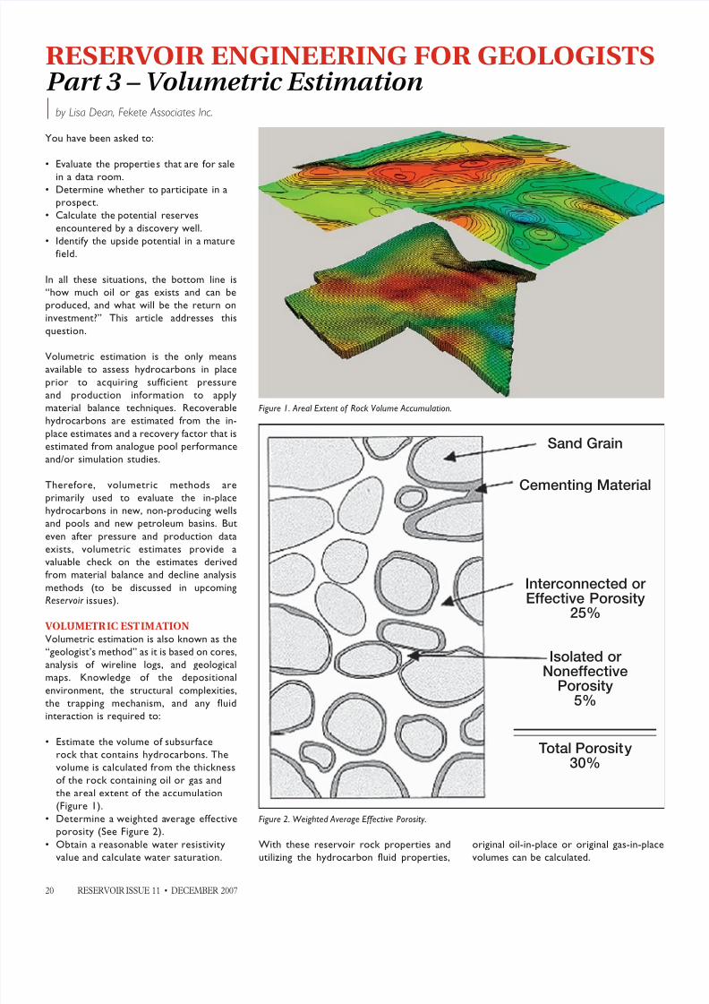
• Determine a weighted average effective
porosity (See Figure 2).
• Obtain a reasonable water resistivity
value and calculate water saturation.
With these reservoir rock properties and
utilizing the hydrocarbon fluid properties,
original oil-in-place or original gas-in-place
volumes can be calculated.
Figure 1. Areal Extent of Rock Volume Accumulation.
Figure 2. Weighted Average Effective Porosity.
Sand Grain
Cementing Material
Interconnected or Effective Porosity
25%
Isolated or Noneffective
Porosity
5%
Total Porosity30%

8/12/2019 Calculos Volumetricos Reservorios
http://slidepdf.com/reader/full/calculos-volumetricos-reservorios 2/4 RESERVOIR ISSUE 11 • DECEMBER 2007 21
For OIL RESERVOIRS the original oil-in-
place (OOIP) volumetric calculation is:
Metric:
OOIP (m3) =
Rock Volume * * (1- Sw) * 1/Bo
Where: Rock Volume (m3) = 104 * A * h
A = Drainage area, hectares
(1 ha = 104m2)
h = Net pay thickness, metres
= Porosity, fraction of rock volumeavailable to store fluids
Sw = Volume fraction of porosity filled
with interstitial water
Bo = Formation volume factor (m3/m3)
(dimensionless factor for the change
in oil volume between reservoir
conditions and standard conditions
at surface)
1/Bo = Shrinkage (Stock Tank m3/reservoir m3 )
= volume change that the oil undergoes
when brought to the earth’s surface
due to solution gas evolving out of
the oil.
Imperial:
OOIP (STB) =
Rock Volume * 7,758 * * (1- Sw) * 1/Bo
Where: Rock Volume (acre feet) = A * h
A = Drainage area, acres
h = Net pay thickness, feet
7,758 = API Bbl per acre-feet (converts
acre-feet to stock tank barrels)
= Porosity, fraction of rock volume
available to store fluids
Sw = Volume fraction of porosity filledwith interstitial water
Bo = Formation volume factor
(Reservoir Bbl/STB)
1/Bo = Shrinkage (STB/reservoir Bbl)
To calculate recoverable oil volumes the
OOIP must be multiplied by the Recovery
Factor (fraction). The recovery factor
is one of the most important, yet the
most difficult variable to estimate. Fluid
properties such as formation volume
factor, viscosity, density, and solution
gas/oil ratio all influence the recoveryfactor. In addition, it is also a function of
the reservoir drive mechanism and the
interaction between reservoir rock and
the fluids in the reservoir. Some industry
standard oil recovery factor ranges for
various natural drive mechanisms are lis ted
below:
Solution gas drive 2 – 30%
Gas cap drive 30 – 60%
Water drive 2 – 50%
Gravity Up to 60%
Petrel ReservoirEngineering
www.slb.com/petrel
*Mark of Schlumberger © 2007 Schlumberger 07-IS-196
PETREL* SEISMIC-TO-SIMULATION SOFTWARE AMPLIFIES THE
IMPACT OF E&P TEAMS. Optimize reservoir performance with a singlesolution. Unite the subsurface domains of geophysics, geology, and reservoir
engineering to evaluate reservoir quality away from well control while honoring
geologic features that impact reservoir performance.
“Being able to run multiple simulations with multiple scenarios really helped
bracket the uncertainty, especially with limited well control in the deepwater
environment. Faster, more accurate answers with a greater range of uncertainties
can be covered in a very short time.” Subsurface Lead, Murphy Oil
Schlumberger Information Solutions—reducing risk for better business results.
Breakthrough Performance.
Better results.
(Continued on page 22...)

8/12/2019 Calculos Volumetricos Reservorios
http://slidepdf.com/reader/full/calculos-volumetricos-reservorios 3/422 RESERVOIR ISSUE 11 • DECEMBER 2007
For GAS RESERVOIRS the original gas-
in-place (OGIP) volumetric calculation is:
Metric:
OGIP (103m3) =
Rock Volume * * (1-SW) *(Ts * Pi)
(Ps * Tf * Zi)
Where: Rock Volume (m3) = 104 * A * h
A = Drainage area, hectares(1 ha = 104m2)
h = Net pay thickness, metres
= Porosity, fraction of rock volume
available to store fluids
Sw = Volume fraction of porosity filled
with interstitial water
Ts = Base temperature, standard
conditions, °Kelvin (273° + 15°C)
Ps = Base pressure, standard conditions,
(101.35 kPaa)
Tf = Formation temperature, °Kelvin
(273° + °C at formation depth)
Pi = Initial Reservoir pressure, kPaa
Zi = Compressibil ity at Pi and Tf
Imperial:
OGIP (MMCF) =
Rock Volume * 43,560 * * (1-Sw) *
(Ts * Pi)
(Ps * Tf * Zi)
Where: Rock Volume (acre feet) = A * h
A = Drainage area, acres
(1 acre = 43,560 sq. ft)
h = Net pay thickness, feet
= Porosity, fraction of rock volume
available to store fluidsSw = Volume fraction of porosity filled
with interstitial water
Ts = Base temperature, standard
conditions, °Rankine (460° + 60°F)
Ps = Base pressure, standard conditions ,
14.65 psia
Tf = Formation temperature, °Rankine
(460° + °F at formation depth)
Pi = Initial Reservoir pressure, psia
Zi = Compressibil ity at Pi and Tf
To calculate recoverable gas volumes, the
OGIP is multiplied by a recovery factor.
Volumetric depletion of a gas reservoir withreasonable permeability at conventional
depths in a conventional area will usually
recover 70 to 90% of the gas-in-place.
However, a reservoir’s recovery f actor can
be significantly reduced by factors such
as: low permeability, low production rate,
overpressure, soft sediment compaction,
fines migration, excessive formation depth,
water influx, water coning and/or behind
pipe cross flow, and the position and number
of producing wells. As an example, a 60%
recovery factor might be appropriate for a
gas accumulation overlying a strong aquifer
with near perfect pressure support.
Rock Volume Calculations (A * h)
Reservoir volumes can be calculated from
net pay isopach maps by planimetering to
obtain rock volume (A * h). To calculate
volumes it is necessary to find the areas
between isopach contours. Planimetering
can be performed by hand or computer
generated. Given the areas between
contours, volumes can be computed using;
Trapezoidal rule, Pyramidal rule, and/or
the Peak rule for calculating volumes (see
Figure 3).
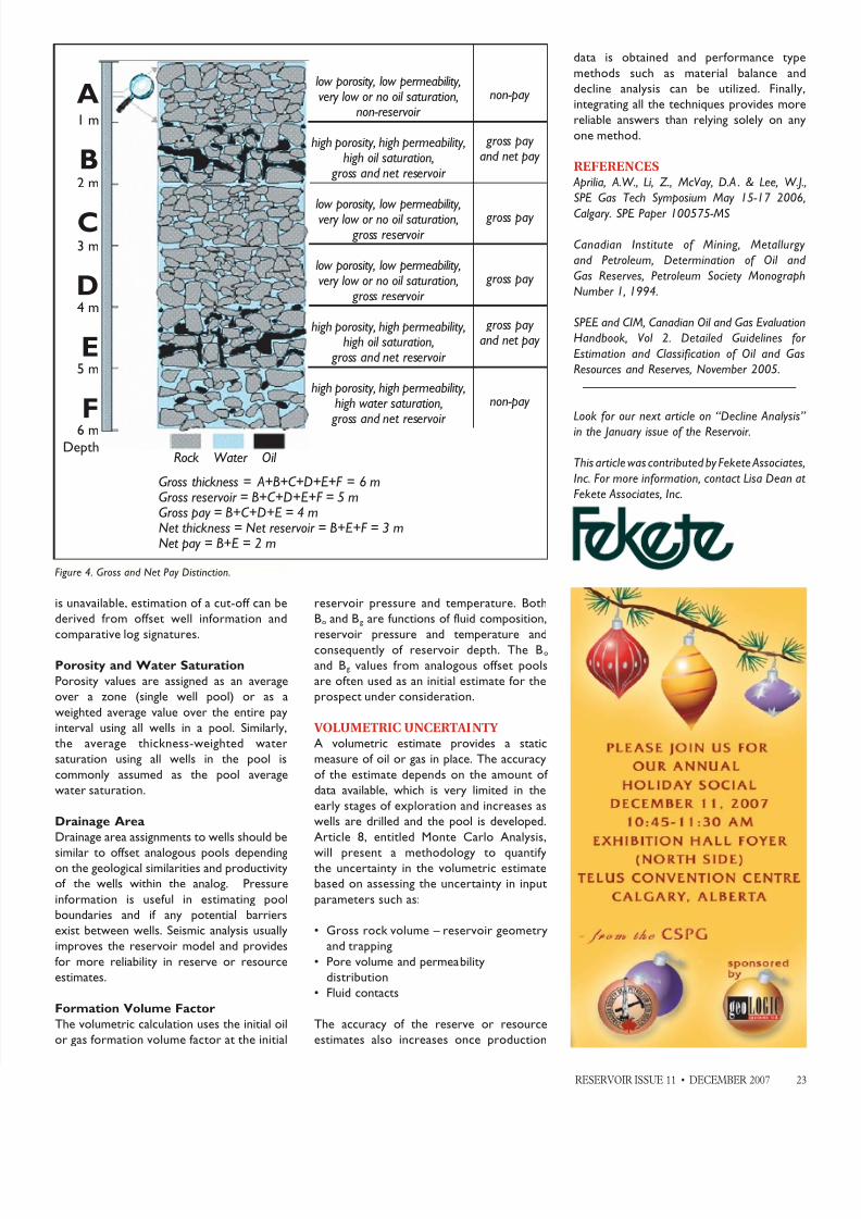
Net pay
Net pay is the part of a reservoir from
which hydrocarbons can be produced ateconomic rates, given a specific production
method. The distinction between gross and
net pay is made by applying cut-off values
in the petrophysical analysis (Figure 4).
Net pay cut-offs are used to identify values
below which the reservoir is effectively
non-productive.
In general, the cut-off values are determined
based on the relationship between porosity,
permeability, and water saturation from
core data and capillary pressure data. If core
(...Continued from page 21)
Figure 3. Volumetric Rules: Trapezoidal, Pyramidal, and Cone.
8/12/2019 Calculos Volumetricos Reservorios
http://slidepdf.com/reader/full/calculos-volumetricos-reservorios 4/4 RESERVOIR ISSUE 11 • DECEMBER 2007 23
is unavailable, estimation of a cut-off can be
derived from offset well information and
comparative log signatures.
Porosity and Water Saturation
Porosity values are assigned as an average
over a zone (single well pool) or as a
weighted average value over the entire pay
interval using all wells in a pool. Similarly,
the average thickness-weighted water
saturation using all wells in the pool is
commonly assumed as the pool average
water saturation.
Drainage Area
Drainage area assignments to wells should be
similar to offset analogous pools dependingon the geological similarities and productivity
of the wells within the analog. Pressure
information is useful in estimating pool
boundaries and if any potential barriers
exist between wells. Seismic analysis usually
improves the reservoir model and provides
for more reliability in reserve or resource
estimates.
Formation Volume Factor
The volumetric calculation uses the initial oil
or gas formation volume factor at the initial
reservoir pressure and temperature. Both
Bo and Bg are functions of fluid composition,
reservoir pressure and temperature andconsequently of reservoir depth. The Bo
and Bg values from analogous offset pools
are often used as an initial estimate for the
prospect under consideration.
VOLUMETRIC UNCERTAINTY
A volumetric estimate provides a static
measure of oil or gas in place. The accuracy
of the estimate depends on the amount of
data available, which is very limited in the
early stages of exploration and increases as
wells are drilled and the pool is developed.
Article 8, entitled Monte Carlo Analysis,
will present a methodology to quantifythe uncertainty in the volumetric estimate
based on assessing the uncertainty in input
parameters such as:
• Gross rock volume – reservoir geometry
and trapping
• Pore volume and permeability
distribution
• Fluid contacts
The accuracy of the reserve or resource
estimates also increases once production
data is obtained and performance type
methods such as material balance and
decline analysis can be utilized. Finally,
integrating all the techniques provides more
reliable answers than relying solely on any
one method.
REFERENCES
Aprilia, A.W., Li, Z., McVay, D.A . & Lee, W.J.,
SPE Gas Tech Symposium May 15-17 2006,
Calgary. SPE Paper 100575-MS
Canadian Institute of Mining, Metallurgy
and Petroleum, Determination of Oil and
Gas Reserves, Petroleum Society Monograph
Number 1, 1994.
SPEE and CIM, Canadian Oil and Gas Evaluation
Handbook, Vol 2. Detailed Guidelines for
Estimation and Classification of Oil and Gas
Resources and Reserves, November 2005.
Look for our next article on “Decline Analysis”
in the January issue of the Reservoir.
This article was contributed by Fekete Associates,
Inc. For more information, contact Lisa Dean at
Fekete Associates, Inc.
Rock Water Oil
Gross thickness = A+B+C+D+E+F = 6 mGross reservoir = B+C+D+E+F = 5 mGross pay = B+C+D+E = 4 mNet thickness = Net reservoir = B+E+F = 3 mNet pay = B+E = 2 m
low porosity, low permeability,very low or no oil saturation,
non-reservoir
high porosity, high permeability,high oil saturation,
gross and net reservoir
low porosity, low permeability,very low or no oil saturation,
gross reservoir
low porosity, low permeability,very low or no oil saturation,
gross reservoir
high porosity, high permeability,high oil saturation,
gross and net reservoir
high porosity, high permeability,high water saturation,
gross and net reservoir
non-pay
gross pay and net pay
gross pay
gross pay
gross payand net pay
non-pay
A1 m
B2 m
C3 m
D4 m
E5 m
F6 m
Depth
Figure 4. Gross and Net Pay Distinction.