CalculationofEffectiveEarthRadiusandPointRefractivity...
5
Hindawi Publishing Corporation International Journal of Antennas and Propagation Volume 2010, Article ID 245070, 4 pages doi:10.1155/2010/245070 Research Article Calculation of Effective Earth Radius and Point Refractivity Gradient in UAE Abdulhadi Abu-Almal and Kifah Al-Ansari Electrical Engineering Department, Ajman University of Science and Technology, Al-Jurf, P.O. Box 346 Ajman, UAE Correspondence should be addressed to Kifah Al-Ansari, [email protected] Received 1 April 2010; Accepted 21 May 2010 Academic Editor: Tat Yeo Copyright © 2010 A. Abu-Almal and K. Al-Ansari. This is an open access article distributed under the Creative Commons Attribution License, which permits unrestricted use, distribution, and reproduction in any medium, provided the original work is properly cited. A large set of 14 years of reliable local radiosonde meteorological data, from 1990 to 2003, has been used to calculate the effective Earth radius and point refractivity gradient in the United Arab Emirates. The obtained values are used to investigate their impact on the design of microwave links. The cumulative distribution of the refractivity gradient in the first 65 meters above the ground surface, the monthly distribution for the median value of the k-factor, as well as their comparison with the ITU-maps are provided. Both experimental and global standard values are applied to specific link budget calculations. 1. Introduction Radio waves may bend while propagating through different atmospheric layers due to variations of refractivity. These variations are determined by meteorological conditions, mainly temperature and humidity, which are strongly vary- ing with the geographical location and time of the year. The whole Gulf region is likely to experience anomalous propagation due to its special climate. In this regard, few studies are available for this region. This work has been conducted for the coastal city of Abu Dhabi that is located at 24.52 ◦ N latitude and 54.98 ◦ E longitudes, with an altitude of 27 m above sea level. The climate is hot and humid most of the year. For microwave link design, some parameters such as the effective earth radius factor, k, and the point refractivity gradient, dN 1 , must be set carefully to optimize its perfor- mance. Both the k-factor, which is directly related to the vertical gradient of refractivity, and dN 1 need to be calculated correctly [1]. Commonly, the k-factor is set as a standard value of 4/ 3, and estimated values of dN 1 are provided by ITU tables for different geographical locations wherever reliable local data are not available [2]. In this paper, long-term experimental radiosounding data, registered in two daily ascents, 0 and 12 hours, have been used to calculate the above values and compare them with the proposed ITU values. 1.1. Effective Earth Radius. It is the radius of a hypothetical spherical Earth, without atmosphere, for which propagation paths follow straight lines, the heights and ground distances being the same as for the actual Earth in an atmosphere with a constant vertical gradient of refractivity [3]. The k-factor can be derived from the vertical refractivity gradient, ΔN , in the first kilometer above the ground. It is obtained from two refractivity values, N s , surface refractivity, and N 1 , refractivity at 1 km height above the ground. Since data at exact heights are not available, the following equation is used [4]: ΔN = N s − N 1 h s − h 1 , (1) where h 1 is the point nearest to 1 km height and ΔN is calculated only if 900 m < h 1 < 1100 m. The statistical analyses of surface refractivity and first kilometer refractivity gradient in Abu Dhabi have been discussed previously in [5]. The k-factor can be calculated from Snell’s law in spherical geometry [3, 6]. This value must be multiplied by the actual Earth’s radius, a, in order to plot the propagation paths as straight lines, as follows: k = 1 (1 + a(dn/dh)) , (2)
Transcript of CalculationofEffectiveEarthRadiusandPointRefractivity...
Hindawi Publishing CorporationInternational Journal of Antennas and PropagationVolume 2010, Article ID 245070, 4 pagesdoi:10.1155/2010/245070
Research Article
Calculation of Effective Earth Radius and Point RefractivityGradient in UAE
Abdulhadi Abu-Almal and Kifah Al-Ansari
Electrical Engineering Department, Ajman University of Science and Technology, Al-Jurf, P.O. Box 346 Ajman, UAE
Correspondence should be addressed to Kifah Al-Ansari, [email protected]
Received 1 April 2010; Accepted 21 May 2010
Academic Editor: Tat Yeo
Copyright © 2010 A. Abu-Almal and K. Al-Ansari. This is an open access article distributed under the Creative CommonsAttribution License, which permits unrestricted use, distribution, and reproduction in any medium, provided the original work isproperly cited.
A large set of 14 years of reliable local radiosonde meteorological data, from 1990 to 2003, has been used to calculate the effectiveEarth radius and point refractivity gradient in the United Arab Emirates. The obtained values are used to investigate their impacton the design of microwave links. The cumulative distribution of the refractivity gradient in the first 65 meters above the groundsurface, the monthly distribution for the median value of the k-factor, as well as their comparison with the ITU-maps are provided.Both experimental and global standard values are applied to specific link budget calculations.
1. Introduction
Radio waves may bend while propagating through differentatmospheric layers due to variations of refractivity. Thesevariations are determined by meteorological conditions,mainly temperature and humidity, which are strongly vary-ing with the geographical location and time of the year.The whole Gulf region is likely to experience anomalouspropagation due to its special climate. In this regard, fewstudies are available for this region. This work has beenconducted for the coastal city of Abu Dhabi that is locatedat 24.52◦ N latitude and 54.98◦ E longitudes, with an altitudeof 27 m above sea level. The climate is hot and humid mostof the year.
For microwave link design, some parameters such as theeffective earth radius factor, k, and the point refractivitygradient, dN1, must be set carefully to optimize its perfor-mance. Both the k-factor, which is directly related to thevertical gradient of refractivity, and dN1 need to be calculatedcorrectly [1]. Commonly, the k-factor is set as a standardvalue of 4/3, and estimated values of dN1 are provided by ITUtables for different geographical locations wherever reliablelocal data are not available [2]. In this paper, long-termexperimental radiosounding data, registered in two dailyascents, 0 and 12 hours, have been used to calculate the abovevalues and compare them with the proposed ITU values.
1.1. Effective Earth Radius. It is the radius of a hypotheticalspherical Earth, without atmosphere, for which propagationpaths follow straight lines, the heights and ground distancesbeing the same as for the actual Earth in an atmosphere witha constant vertical gradient of refractivity [3].
The k-factor can be derived from the vertical refractivitygradient, ΔN , in the first kilometer above the ground. It isobtained from two refractivity values,Ns, surface refractivity,and N1, refractivity at 1 km height above the ground. Sincedata at exact heights are not available, the following equationis used [4]:
ΔN = Ns −N1
hs − h1, (1)
where h1 is the point nearest to 1 km height and ΔN iscalculated only if 900 m < h1 < 1100 m. The statisticalanalyses of surface refractivity and first kilometer refractivitygradient in Abu Dhabi have been discussed previously in [5].
The k-factor can be calculated from Snell’s law inspherical geometry [3, 6]. This value must be multiplied bythe actual Earth’s radius, a, in order to plot the propagationpaths as straight lines, as follows:
k = 1(1 + a(dn/dh))
, (2)

2 International Journal of Antennas and Propagation
where a is usually given in nautical miles, nmi, rather thankilometers, km (a = 6371 km = 3440 nmi), and dn/dh is therate of change of the refractive index with height, knowingthat N = (n− 1)× 106.
Alternatively, the median k-factor may also be calculatedusing the median ΔN as follows [1]:
k = 157157− ΔN . (3)
1.2. Point Refractivity Gradient. The vertical refractivity gra-dient in the lowest 100 meters of the troposphere above theground is an important parameter to estimate propagationeffects such as ducting, surface reflection, and multipath onterrestrial line-of-sight links. dN1 is the point refractivitygradient in the lowest 65 m of the atmosphere not exceededfor 1% of an average year [2, 7]. The dN1 value is obtainedusing (1), where N1 is calculated considering the h1 valuenearest to 65 m height, so that 60 m < h1 < 70 m.
2. Results and Analysis
2.1. k-Factor. The refractivity gradient for the first kilometerhas been calculated for fourteen years in Abu Dhabi city.The values have been found to vary between −200 and63 N/km [5]. The long-term median value of ΔN has alsobeen derived yielding a value equal to −71.3 N/km, while theglobal standard value is −40 N/km [6]. Accordingly, using(3), a k-factor value of 1.83 has been obtained, while itsglobal standard value is 4/3 [6], with an absolute differenceof 0.5.
The monthly distribution of median ΔN has beencalculated, showing variations from −47 to −107 N/km.These values, using (3), produce the corresponding k-factordistribution as shown in Figure 1. It must be noted thatthe experimental k-factor presents a large variability from1.43 to 3.17 which is always above 4/3. The highest valuescorrespond to the summer months of June and July. The k-factor value, 3.18, might be considered in some conditions asthe worst case; otherwise the long-term median value shouldbe used taking into account the probability of link outageduring summer time.
2.2. Point Refractivity Gradient. Figure 2 shows the cumula-tive distribution of the refractivity gradient at 65 m heightfrom the ground in Abu Dhabi. The value of dN1 notexceeded for 1% of the time for the full measurement periodis −1029 N/km. The obtained gradient values for differenttime percentages in comparison with ITU maps are givenin Table 1. Bilinear interpolation has been used to get exactvalues of ΔN from the maps for the site coordinates. Theresults are in good agreement with the ITU values for thepercentages of 1% and 50%. Some differences are observedwhich might otherwise be attributed to the high variabilityand abnormality of the climatic parameters of the region.
2.3. Microwave Link Budget Analysis. The values obtained forboth parameters have been investigated using a specializedsoftware-planning tool to find out their impact on the
121110987654321
(months)
1.2
1.4
1.6
1.8
2
2.2
2.4
2.6
2.8
3
3.2
3.4
k-fa
ctor
Figure 1: Monthly distribution of median k-factor.
4002000−200−400−600−800−1000−1200
Refractivity gradient (N/km)
0
10
20
30
40
50
60
70
80
90
100
Tim
e(%
)
Figure 2: Cumulative distribution of the refractivity gradient at65 m.
Table 1: Values of dN not exceeded for different time percentagescompared with ITU maps.
Time percentage ITU values (N/km) Obtained values (N/km)
1% −952.42 −1029
10% −553 −333.5
50% −92.824 −108
90% −4.38 63.6
99% 38.86 293.6
microwave link performance [8]. A significant number oflinks, operating within the microwave network of UAE alongthe coastal line of the Gulf including Abu Dhabi, havebeen considered for this test. Results for two point-to-pointmicrowave links currently in operation in a region withrelatively flat terrain without buildings are presented below.
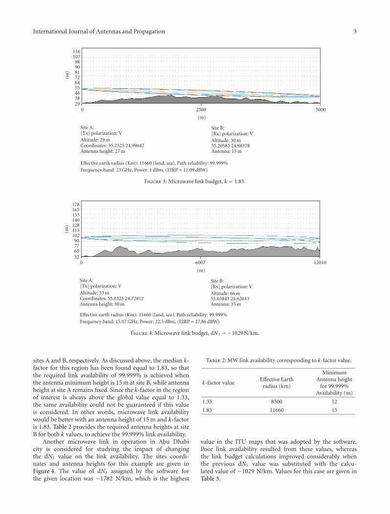
Figure 3 shows the path profile of a microwave link withtwo antenna heights of 27 m and 15 m above the ground, at
International Journal of Antennas and Propagation 3
500025000
(m)
293846556472819098
107116
(m)
Site A:[Tx] polarization: VAltitude: 29 mCoordinates: 55.2525 24.99642Antenna height: 27 m
Site B:[Rx] polarization: VAltitude: 30 m55.20583 24.98378Antenna: 15 m
Effective earth radius (Km): 11660 (land, sea), Path reliability: 99.999%Frequency band: 23 GHz, Power: 1 dBm, (EIRP = 11.09 dBW)
Figure 3: Microwave link budget, k = 1.83.
1201060070
(m)
52657790
102115128140153165178
(m)
Site A:[Tx] polarization: VAltitude: 53 mCoordinates: 55.0323 24.72812Antenna height: 50 m
Site B:[Rx] polarization: VAltitude: 66 m55.03843 24.62033Antenna: 35 m
Effective earth radius (Km): 11660 (land, sea), Path reliability: 99.999%Frequency band: 15.07 GHz, Power: 22.5 dBm, (EIRP = 27.86 dBW)
Figure 4: Microwave link budget, dN1 = −1029 N/km.
sites A and B, respectively. As discussed above, the median k-factor for this region has been found equal to 1.83, so thatthe required link availability of 99.999% is achieved whenthe antenna minimum height is 15 m at site B, while antennaheight at site A remains fixed. Since the k-factor in the regionof interest is always above the global value equal to 1.33,the same availability could not be guaranteed if this valueis considered. In other words, microwave link availabilitywould be better with an antenna height of 15 m and k-factoris 1.83. Table 2 provides the required antenna heights at siteB for both k values, to achieve the 99.999% link availability.
Another microwave link in operation in Abu Dhabicity is considered for studying the impact of changingthe dN1 value on the link availability. The sites coordi-nates and antenna heights for this example are given inFigure 4. The value of dN1 assigned by the software forthe given location was −1782 N/km, which is the highest
Table 2: MW link availability corresponding to k-factor value.
k-factor valueEffective Earth
radius (km)
MinimumAntenna height
for 99.999%Availability (m)
1.33 8500 12
1.83 11660 15
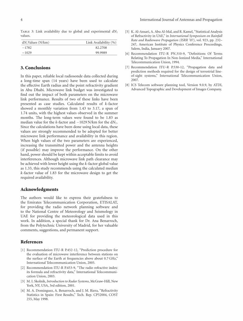
value in the ITU maps that was adopted by the software.Poor link availability resulted from these values, whereasthe link budget calculations improved considerably whenthe previous dN1 value was substituted with the calcu-lated value of −1029 N/km. Values for this case are given inTable 3.
4 International Journal of Antennas and Propagation
Table 3: Link availability due to global and experimental dN1
values.
dN1Values (N/km) Link Availability (%)
−1782 82.2708
−1029 99.9989
3. Conclusions
In this paper, reliable local radiosonde data collected duringa long-time span (14 years) have been used to calculatethe effective Earth radius and the point refractivity gradientin Abu Dhabi. Microwave link budget was investigated tofind out the impact of both parameters on the microwavelink performance. Results of two of these links have beenpresented as case studies. Calculated results of k-factorshowed a monthly variation from 1.43 to 3.17, a span of1.74 units, with the highest values observed in the summermonths. The long-term values were found to be 1.83 asmedian value for the k-factor and −1029 N/km for the dN1.Since the calculations have been done using local data, thesevalues are strongly recommended to be adopted for bettermicrowave link performance and availability in this region.When high values of the two parameters are experienced,increasing the transmitted power and the antenna heights(if possible) may improve the performance. On the otherhand, power should be kept within acceptable limits to avoidinterferences. Although microwave link path clearance maybe achieved with lower height using the k-factor global valueas 1.33, this study recommends using the calculated mediank-factor value of 1.83 for the microwave design to get therequired availability.
Acknowledgments
The authors would like to express their gratefulness tothe Emirates Telecommunication Corporation, ETISALAT,for providing the radio network planning software andto the National Centre of Meteorology and Seismology inUAE for providing the meteorological data used in thiswork. In addition, a special thank for Dr. Ana Benarroch,from the Polytechnic University of Madrid, for her valuablecomments, suggestions, and permanent support.
References
[1] Recommendation ITU-R P.452-12, “Prediction procedure forthe evaluation of microwave interference between stations onthe surface of the Earth at frequencies above about 0.7 GHz,”International Telecommunication Union, 2005.
[2] Recommendation ITU-R P.453-9, “The radio refractive index:its formula and refractivity data,” International Telecommuni-cation Union, 2003.
[3] M. I. Skolnik, Introduction to Radar Systems, McGraw-Hill, NewYork, NY, USA, 3rd edition, 2001.
[4] M. A. Dominguez, A. Benarroch, and J. M. Riera, “RefractivityStatistics in Spain: First Results,” Tech. Rep. CP52004, COST255, May 1998.
[5] K. Al-Ansari, A. Abu Al-Mal, and R. Kamel, “Statistical Analysisof Refractivity in UAE,” in International Symposium on RainfallRate and Radiowave Propagation (ISRR ’07), vol. 923, pp. 232–247, American Institute of Physics Conference Proceedings,Salem, India, January 2007.
[6] Recommendation ITU-R PN.310-9, “Definitions Of TermsRelating To Propagation In Non-Ionized Media,” InternationalTelecommunication Union, 1994.
[7] Recommendation ITU-R P.530-12, “Propagation data andprediction methods required for the design of terrestrial line-of-sight systems,” International Telecommunication Union,2007.
[8] ICS Telecom software planning tool, Version 9.0.9, by ATDI,Advanced Topographic and Development of Images Company.

International Journal of
AerospaceEngineeringHindawi Publishing Corporationhttp://www.hindawi.com Volume 2010
RoboticsJournal of
Hindawi Publishing Corporationhttp://www.hindawi.com Volume 2014
Hindawi Publishing Corporationhttp://www.hindawi.com Volume 2014
Active and Passive Electronic Components
Control Scienceand Engineering
Journal of
Hindawi Publishing Corporationhttp://www.hindawi.com Volume 2014
International Journal of
RotatingMachinery
Hindawi Publishing Corporationhttp://www.hindawi.com Volume 2014
Hindawi Publishing Corporation http://www.hindawi.com
Journal ofEngineeringVolume 2014
Submit your manuscripts athttp://www.hindawi.com
VLSI Design
Hindawi Publishing Corporationhttp://www.hindawi.com Volume 2014
Hindawi Publishing Corporationhttp://www.hindawi.com Volume 2014
Shock and Vibration
Hindawi Publishing Corporationhttp://www.hindawi.com Volume 2014
Civil EngineeringAdvances in
Acoustics and VibrationAdvances in
Hindawi Publishing Corporationhttp://www.hindawi.com Volume 2014
Hindawi Publishing Corporationhttp://www.hindawi.com Volume 2014
Electrical and Computer Engineering
Journal of
Advances inOptoElectronics
Hindawi Publishing Corporation http://www.hindawi.com
Volume 2014
The Scientific World JournalHindawi Publishing Corporation http://www.hindawi.com Volume 2014
SensorsJournal of
Hindawi Publishing Corporationhttp://www.hindawi.com Volume 2014
Modelling & Simulation in EngineeringHindawi Publishing Corporation http://www.hindawi.com Volume 2014
Hindawi Publishing Corporationhttp://www.hindawi.com Volume 2014
Chemical EngineeringInternational Journal of Antennas and
Propagation
International Journal of
Hindawi Publishing Corporationhttp://www.hindawi.com Volume 2014
Hindawi Publishing Corporationhttp://www.hindawi.com Volume 2014
Navigation and Observation
International Journal of
Hindawi Publishing Corporationhttp://www.hindawi.com Volume 2014
DistributedSensor Networks
International Journal of