Calculation VYC-2043, Revision 0, 'Evaluation of Primary … · 2012-11-29 · From ASME VI11 1965...
75
VY. CALCULATION TITLE PAGE VYC-2043 REVISION 0 NIA NiA Revision Number IY Calculation Number Revision Number Vendor Calculation Number ride: EVALUATION OF PRIMARY CONTAINME NT LOCALIZED THINNTNG AND SCREENING CRITERIA FOR ASME XI IWE INSPECTIONS :alculation Supports A Design Change/Specification? Yes x No NIA VYDCIMMITMISpec No. hlculation Supports An Independent Analysis? Yes x No Zalculation Done as a Study Only? Yes iafety Evaluation Number: !/A luperseded Calculation Number, Title and Revision:- Nom NIA Reference No bview and Approval: (Print and Sign Name) Date: 11/21/99 Interdiscipline Reviewer(s): )pen Items Associated with Calculation? Yes No - Closed nstallation Verification Calculation accurately reflects plant as-built configuration, OR - X N/A, calculation does not affectplant confguration -William J. Duffv Printed Name VYAPF 0017.01 (Sample) AP 0017 Rev. 5 Page I of 1
Transcript of Calculation VYC-2043, Revision 0, 'Evaluation of Primary … · 2012-11-29 · From ASME VI11 1965...

VY. CALCULATION TITLE PAGE
VYC-2043 REVISION 0 NIA NiA Revision Number I Y Calculation Number Revision Number Vendor Calculation Number
ride: EVALUATION OF PRIMARY CONTAINME NT LOCALIZED THINNTNG AND SCREENING CRITERIA FOR ASME XI IWE INSPECTIONS
:alculation Supports A Design Change/Specification? Y e s x No NIA VYDCIMMITMISpec No.
hlculation Supports An Independent Analysis? Y e s x No
Zalculation Done as a Study Only? Y e s
iafety Evaluation Number: !/A luperseded Calculation Number, Title and Revision:- Nom
NIA Reference
No
bview and Approval: (Print and Sign Name)
Date: 11/21/99
Interdiscipline Reviewer(s):
)pen Items Associated with Calculation? Y e s No - Closed
nstallation Verification
Calculation accurately reflects plant as-built configuration, OR - X N/A, calculation does not affect plant confguration
-William J. Duffv Printed Name
VYAPF 0017.01 (Sample) AP 0017 Rev. 5 Page I of 1

. _
VYC-2043
. . .. . . . . . . . . . -: '
W CALCULATION DATABASE INPUT FORM 0 NIA NIA
V Y CalcuIationlCCN Number Revision Number Vendor Calculation Number Revision Number
Vendor Name: N/A PONumber: N/A
Calculation Type (Originating Department): MECHANXCAUSTRUCTURAL DESIGN ENGINEERING DEPT. Implementation Required? -Yes X NO AssetEquipment ID Number(s):
AssetlSystem ID Nmber(s): PRIMARY CONTAINMENT
Keywords: DRYWELL. ASME CODE IWE INSPECTION, PRIMARY CONTAINMENT
.~
General References
Design Input Documents - The following documents provide design input to this calculation.
-
I Design Output Documents - This calculation provides output to the following documents.
Document Title Critical R c f m c e (J Document # None
VYAPF 0017.09 (Sample) AP 0017 Rev. 5 Page 2 of

,-,.-.: _.._ ... > l . :. . . 7. . . ... .. . .I . . . . - . . I . : . , :..~~,,~ I * _ . . . - . .. ... .,.._. '. ..I .
. . . . . . . . ...:...: i. .. -.. ..La- . . - _ .. . .
VY CALCULATION SHEET p - T i t [ e EVALUATION OF PRIMARY CONTAINMENT LOCALIZS THINNING AND SCREENING CRITERIA FOR ASME XI IWE INSPECTIONS
Calculation Number WC-2043 Revision 0 PAGE 3 OF _.__
PREPARED BY REVIEWEDBY DATE'\\/^,^ W
1
SECTION TABLE OF CONTENTS
PAGE NO.
Cover Sheet ...........,,.......................,,.,...........................................................,.~......................,.. 1
W Calculation Database Input Form (WAPF 0017.07) ........................................,..............,.... 2
Table of Contents .........................................................................................,............................. 3
Introduction ... . . . , . . . . , + .. ... . , . . . . .. . . .. ., . , . . ... . . . ,. . . . . . . . ... . . . . .. . .. .. . , . .. . . .. . . . .. . . . . ... . . . ... . . . . . . . . . ... . 4
Calculation Objective ........................,......... .... ............. .............. . ....... ........ ......... . ................... ... 4
Design Criteria - Analysis Inputs ........ ........... ............. .................. .... ... ....................... ...... . ..... .. 5
Assumptions ....... ....... ...... .... .. .. ....... ,............................,.............. ........................ ................ ... .... 6
Method of Solution ..................... . ....,........................................,.........,... ............ . ............... . ...... 6
Calculation . ..... . . . . . . . . . .. . . . . ... . .. . . . . . . . . . . . . . . . .. . .. . . . . .. . .. , . .. . . . . . . . *. . . . .. . . .. , . . . . . . . . . .. . . . . . . . . ,.. . . . ..... ...... .... .... . . . .7 Summary of Results ...............................................................,...,......,.......,,........ ..................... 25
References . , ... . . . . . . . . . .. . . . . . . . . . . . . . . . . . . . . . .. , . . . . . . . . . ... . . -. . . . .. . . . . .. . .. . , . . . . . . . , . . , . . . . . .. . , . . . . . . . .. . . . . . . . . . . . . . . . . . . . . . . . . .26
Conclusion . , . . . . . .. . . . , .. . . . . . .. . . ..... . .. . .... . , . , . , . . . . . , . . . . . .. , , , ... . . .... , . . . . . . .. , ... .. . .. .. , .. . . . , . , . . , .. . . . . . . . .. . . . , . . . . . .. . . . . . 27
VY Calculation review Form.. ,... . .............. ................ . , ........... ........ ...... .... , ............ ............ ........ 28
Review Checklist ..........,..............,.,.................,...................,..,.....,...........,.,......,..... 1 ............... 29-31
Attachments Pages A. Excerpts from Chicago Bridge & Iron, "Certified Stress Report, . . . . . . . . . . . . . . . . . . . . . . . . . . . . . . .18
B. Teledyne Engineering Services (TES), Calculation Package 7426-1 , .... . . . . . . . . . . . . . .. . ... . . .12 C. Drywell IWE Examination Reports €or the Elevation 238.' Area.. .. .. , . ..... . . . , . . . , . ..... . . . -14
Vernon II, Containment Vessel", dated October 29, 1968.
"Vermont Yankee Shell Thickness Requirements", Appendix By
Total Pages.. . . . . . . . . . . . . .75

W CALCULATION SHEET
THINNING AND SCREENING CRITERIA FOR ASME XI M INSPECTIONS
Calculation Number wc-2043 Revision 0 PAGE 4 OF - -de EVALUATION OF PRIMARY CONTAINMENT LOCALIZEF
PREPAREDBY DATE///z//W RWLEWEDBY %w DATE %& 119 .
INTRODUCTION
The Drywell is a bulb shaped welded steel vessel housing the primary nuclear reactor vessel, he coolant recirculating lines and pumps, the control rods and other systems. The original lesign of this vessel is documented in the Certified Stress Report, reference 4, performed by 3hicago Bridge & Iron (CB&I) in 1968. The original design did not account for any corrosion nduced wall loss in the steel Drywell shell. During refueling outages, ASME Code, Section XI, Subsection IWE, reference 5, inspections of this vessel are performed. These inspections are risual inspections of the coatings. When base metal corrosion is found any defects are 3valuated by engineering. These defects are generally minor in nature and are normally 'ound acceptable without any further action. The purpose of this calculation is to provide a screening criteria basis and document areas of the Drywell where wall loss due to corrosion =an be accepted.
CALCULATION OBJECTIVE
To provide a screening ctiteria for the evaluation of wall loss from corrosion of the steel lrywell shell. This screening criteria will be used for evaluation of inspection results from the tisual inspections performed under ASME Code Section XI, Subsection IWE, reference 5.
me criteria will be based on the original analysis performed by CB&l, reference 4. This malysis considered 9 different load cases to design the vessel. The first 3 cases are for the nitial vessel test conditions and will not be included in this evaluation. Using the reference 4 stress data, the shell thickness will be determined for general corrosion, localized thinning and 3 bounding calculation for possible corrosion on the internal shell at the concrete slab shell ntersection at elevation 238'.

. . ,:>; . .
VY CALCULATION'SHEET CCN Number N/A Title EVALUATION OF PRIMARY CONTAMMENT LOCALED THINNING AND SCREENlNG CRITERIA FOR ASME XI IWE INSPECTIONS
PREPARED BY DATE /(/2!/99 REVIEWED BY JaC?- DATE [I /qqq ,
Calculation Number WC-2043 Revision 0 PAGE 5 OF -
V
DESIGN CRlTERlA I ANALYSIS INPUTS
The Vermont Yankee Primary Containment is Safety Class 2
The original construction code for the primary containment was for a type 6 vessel in accordance with ASME Section I l l , 1965 edition with Addenda to Winter of 1965. Paragraph N-1111 in this edition of Section 111 specifies the rules of Division 1 of Section Vlll (with exceptions) shall apply to the design, fabrication, inspection, testing, and certification of Class B vessels.
Also Paragraph N-I314(a) requires that the requirements of Paragraphs N-414.1 to N-414.4 be met for the stress values specified in Paragraph N-l314(b). The stress intensity values (Sm) used are the allowable stress values at design temperature as tabulated in Division I of Section VIII.
The internal design pressure is 56. Psi., and the external design pressure is 2 Psi., references 3,4, at 7.
The primary containment is constructed of SA51 6 Gr.70 (FBX to A300) steel plate. The plates have specified minimum tensile strength of 70,000 Psi. and a minimum yield strength of 38,000 Psi. The welds are 100% radiographed. The allowable stress value (and allowable' stress intensity, Sm) at design temperature (281 F) is 17,500. Psi. See reference 4.
The Drywell was designed for Pressure, deadweight, live loads, refueling water, vent thrusts, and seismic loads in six different load combinations. Another three combinations that dealt with initial testing were not considered in this evaluation.

W CALCULATION SHEET Calculation Number wc-2043 Revision 0 PAGE -NfB TdIe EVALUATION OF PRIMARY CONTAINMENT LOCALIZED THINNING AND SCREENfNG CRITERIA FOR ASME XI M E INSPECTIONS
PREPAREDBY DATE/I !p! lqq REVlMlEDBY DATE \\/h/?? .
OF -
V ASSUMPTIONS
1, 100 full DBA cycles ( from negative 2 Psi. to the design pressure of 56.0 Psi.) will be used to evaluate peak stresses. This includes Type A containment pressure tests and should envelope the initial pressure test. 100 cycles would represent approximately 2.5 tests per year over the 40 year Me of the plant. The evaluation for pits and surface defects in the calculation section of this calculation demonstrates that there is significant margin in both the number of alternating stress cycles and in the magnitude of the atternating stresses evaluated. The assumption is valid and sufficient for the purposes of this calculation.
METHOD OF SOLUTION
Using hand analysis techniques an acceptance criteria for wall loss due to corrosion andlor Near based on the original design code requirements was developed. (
A. Mil! under tolerance of lesser of 0.01" or 6% whichever is less based on ASME Code, Section VIII, 1965 Paragraph UG-I6(c).
B. Based on design report margin exists for general wall loss in specific regions. The Drywell shell is constructed of plates that vary in thickness at different locations. These areas will be checked to determine if any conservatism exists in the installed wall thickness.
2. Localized thinning:
General criteria for localized pitting /small surface effects will be provided. A procedure for evaluation of localized thinning will be developed based on:
a) simplified method b) adaptation of Teledyne Engineering Services calculations for of a
. (Attachment B) generic stress evaluation for localized thinning in a circular plate
3. A bounding calculation for possible corrosion internal to drywell at the intersection of the concrete slab at elevation 238.

I. ~ ,..,. ..’.,___ : . . . . . . ,: .I .. .. . .. ~ . -.. . . . I . . .
w CALCULATION SHEET
THINNING AND SCREENING CRITERIA FOR ASME XI IWE INSPECTlONS PREPAREDBY DATEIdZ I /V RRJlEWEDBY <* DATE.*
Calculation Number wc-2043 Revision 0 PAGE 7 OF - -de EVALUATION OF PRIMARY CONTAINMENT LOCALIZED
ZALCULATION v 4s shown on the design drawings, reference 7, the wall thickness varies with location on the jrywell shell. No allowance for corrosion was included. Due to the complex geometry, the drywell portions of the design report do not contain simplified minimum wall thickness calculations. The drywell is designed by analysis. The required wall thickness is controlled by the design report.
General Corrosion
There are three separate models/analyses; (A) Top cylinder to sphere thin shell model, (B) Sphere model with member nodes, and (C) Local model at the Sand Transition. I
From ASME VI11 1965 Paragraph UG-I6(c), the permissible mill under-tolerance for the exterior shell plates to allow for use of the full design pressure is the smaller of 0.01 inch or 6 percent of the ordered thickness. From reference 4, page IC-IO and reference 7, the wail thickness varies from 0.635 inches up to 2.5 inches. Using the calculated design stresses contained in reference 4, the shell thickness will be recalculated based on the Stress Intensity Allowable Limits.
4i
*
See Figures on foltowing pages for locations of stresses.
From Top Portion of Drywell Model (A)
From Reference 4, Page lA2
Primarv General Membrane Stress lntensitv (PA c
Location
Top Head Cylinder,, Cylinder,
Cone Cylinder, Cylinder,, Knuckle Sphere
Stress Intensity
Lllgn rn (inch) (Psi) 1.31 25 8173 1.25 7778 4.5 3044 I .25 11448 1.25 9598 0.635 17498 2.4375 16457 0.6875 15481
Allowable
S (Psi)
17500 17500 17500 17500 17500 17500 17600 d 7500
-- a 0.47 0.44 0.1 7 0.65 OS5 1 .oo 0.94 0.88
&&&A&&
fhlln. (inch) 0.6130 0.5556 0.2609 0.81 77 0.6856 0.6349 2.2922 0.6082

~
.... . . . . - . , , .. . . . ,.. . . . . . . - -.. ..
VY CALCULATION SHEET Calculation Number VYC-2043 Revision 0 PAGE - OF CCN Number N/A THINNING AND SCREENING CRlTERlA FOR ASME XI IWE INSPECTiONS
PREPAREDBY
Title EVALUATION OF PRIMARY CONTAINMENT LOCALIZED
I V
MODEL (A)

. . . .
VY CALCULATION SHEET Calculation Number VYC-2043 Revision 0 PAGE 9 OF
CCN Number N/A THlNNlNG AND SCREENING CRITERIA FOR ASME XI IWE INSPECTIONS
Title EVALUATION OF PRIMARY CONTAlNMENT LOCALIZED
PREPARED BY DATE {!h/?b REVIEWED BY OATE 11 % V

Vy CALCULATION SHEET
THINNING AND SCREENING CRITERIA FOR ASME XI IWE INSPECTIONS
PREPAREDBY DATE,JbI/W R M M D B Y & DATE \ ! h ! ? j .
Calcufation Number VYc-2043 Revision 0 PAGE /o OF - Title EVALUATION OF PRIMARY CONTAINMENT LOCALIZED
j L . 238.00-
EL. 295.4870

w CALCULATION SHEET Calculation Number VYC-2043 Revision 0 PAGE - I OF - rHINNlNG AND SCREENING CRITERIA FOR ASME XI IWE INSPECTIONS
JREPARED BY vm DATE I f?2,/99 REVIEWED BY & DATE \!,wqq . EVALUATION OF PRIMARY CONTAINMENT LOCALIZED
CALCULATION - gontinued - General Corrosion Model (A)
From Reference 4, Page lA2
Prirnarv Local Membrane Stress lntensity IPJ - Stress Allowable celn.ss&m c - Intensity
Location hen (p3 - R - /I .!is, - &in.
Top Head 1.3125 9188 26250 . 0.35 0.4594 (inch) (Psi) (Psi) (inch)
From Reference 4, Page lA3
Primarv+Secondarv Membrane + Bending Stress lntensitv (P,,P,+ 41
Location
Top Head Cylinder, Cylinder,
Cone Cylinder, Cylinder, Knuckle Sphere
L (inch) I .3125 4.25 1.5
1.25 1.25 0.635 2.4375 0.6875
stress Intensity
(PSI) 13246 8667
45262 40628 40628 17934 18819 18944
Atlowa bfe
3s (PSI)
52500 52500 52500 52500 52500 52500 52500 52500
-- 0.50 0.41 0.93 0.88 0.88 0.58 0.60 0.60
EQ (1) * toftsign
f y
(inch) 0.6593 0.5079 1.3928 1.0996 1.0996 0.371 1 1.4594 0.41 30

- . . . -. - . . .
W CALCULATfON SHEET Calculation Number wc-2043 Revision 0 PAGE
THINNING AND SCREENING CRITERIA FOR ASME XI IWE INSPECTIONS
PREPAREDBY DATE 11/2//+9 REVlMtEDBY DATE \!lz5('i? .
OF __ €VALUATION OF PRIMARY CONTAINMENT LOCALIZED
;ALCUlATION -kontinued - General Corrosion JlodellS) SDhere +om Reference 4, Page IC10 for Vessel sphere
'rimam General Membrane Stress Intensity (PA -
Location
Bot Of Cylinder Point I Point 2 Point 3 Point 4 Point 5 Point 6 Point 7 Point 8 Point 9 Point 10 Point I 1
Stress Intensity
_/Pml (Psi)
0.635 17450
2.4375 2.4375 2.4375 0.6875 0.6875 0.6875 0.8125 0.8125 1 .oooo 1 .oooo 1 .I 25
8727 17487 16276 16289 16167 16314 14096 14524 12423 13468 12930
Allowable (Tension)
S
17500
'I7500 97500 17500 17500 17500 17500 17500 17500 17500 17500 17500
(31
Wmarv General Membrane Stress lntensitv (PA -
Location
Bot Of Cylinder Point 1 Point 2 Point 3 Point 4 Point 5 Point 6 Paint 7 Point 8 Point 9
Point I O Point I 1
Stress Intensity
Llgn 0 (inch) (Psi) 0.635 1210
2.4375 2.4375 2.4375 0.6875 0.6875 0.6875 0.81 25 0.8125 1 .oooo I .oooo 1 .I 25
452 1130 2925 1659 1291 4374 1476 1954 2293 3547 4308
Allowable (Compress)
S
(Psi) 17500
17500 17500 17500 3326 3326 3326 3931 3931 4839 4839 5444
--m
PJ&
I .oo 0.50 1 .oo 0.93 0.93 0.92 0.93 0.81 0.83 0.71 0.77 0.74
- -
0.07
0.02 0.06 0.17 0.50 0.39 0.41 0.38 0.50 0.47 0.73 0.79
G!s&!sE f i n .
(in%) 0.6332
I 21 55 2.4357 2,2670 0.6399 0.6351 0.6409 0.6545 0.6743 0.7099 0.7696 0.8312
vwi?aE -tAun.
(inch) 0.0439
0.0629 0.1 574 0.4074 0.3429 0.2669 0.2840 0.3051 0.4039 0.4739 0.7330 0.8902

. . . . . .
I I i
ZALCULATION - gontinued - General Corrosion Vlodet (C) Sand Transition
%om Reference 4, Page 1BA2 for Sand Transition
Jrimarv Local Membrane Stress lntensitv (PJ -
Location
TOP 0.50' 1 .I 0" 2.10" 3.00' 4.00" 5.00' 6.00'
Bottom
fDeslgn
(inch) 1.000 1.000 1.125 1.125 1.125 1.125 I .I 25 1.125 1.125
Stress Intensity m
(VU 19643 20689 18730 18900 18860 17730 15840 12850 1 1800
Allowable
1.5s, - (PSI)
26250 26250 26250 26250 26250 26250 26250 26250 26250
0.75 0.79 0.71 0.72 0.72 0.68 0.60 0.49 0.45
%manr+Secondarv Membrane + Bending Stress lntensitv tP?P=+ Q)
Location
TOP 0.50" 1 .I 0" 2.10" 3.00'' 4.00' 5.00" 8.00"
Bottom
8 0 0
(inch) 1.000 1 .ooo 1.1 25 1.125 1.125 I .125 I .125 1.125 1.125
Stress Intensity (P, + P, + Q)
(Psi) - - 22794 25363 24230 20590 24560 19800 20200 1931 0 25550
Al!owable
3s
(PSU 52500 52500 52500 52500 52500 52500 52500 52500 52500
-- 0.66 0.70 0.68 0.63 0.68 0.61 0.62 0.61 0.70
fl,. (inch) 0.7483 0.7881 0.8027 0.8100 0.8083 0.7599 0.6789 0.5507 0.5057
EQ (1) * be8,pn
fa. (inch) 0.6589 0.6951 0.7643 0.7045 0.7695 0.6909 0.6978 0.6823 0.7848

. . . . . . . .
W CALCULATION SHEET
THINNING AND SCREENING CRITERIA FOR ASME XI WE INSPECTIONS
PREPARED BY
Calculation ff umber VYc-2043 Revision 0 PAGE & OF - T d e E V !
DATE 12 1/99 REVIEWED BY L- DATE&&.-
2ALCULATION - antinued - General Corrosion
:ontrollha Mlnimum Thickness for each section based on above :alculations
&?fer to appropriate =igures on pgs 8 to 10
Mod81 (A)
Location
Top Head Cylinder, Cy1 inder,
Cone Cy1 i nder, Cylinder,, Knuckle Sphere
Model (B..
3rvwell Sphere
Bot. Of Cylinder Point 1 Point 2 Polnt 3 Point 4 Point 5 Point 6 Point 7 Point 8 Point 9 Point t 0 Point II
LA (inch) 1.3125 1.25 1.5 1.25 1.25
0.635 2.4375 0.6875
0.635
2.4375 2.4375 2.4375 0.6875 0.6875 0.6875 0.8125 0.81 25 1 .oooo 1.0000 I .I 25
4nhl
(inch) 0.6593 0.5556 1.3928 1.0996 1 .O996 0.6349 2.2922 0.6082
0.6332
I.2155 2.4357 2.2670 0.6399 0.6351 0.6409 0.6545 0.6743 0.7099 0.7696 0.8902
Cor. Allow
0.6532 0.6944 0.1072 0.1 504 0.1504 1E-04 0.1453 0.0793
0.001 8
1.222 0.001 8 0.1705 0.0476 0.0524 0.0466 0.158 0.1302 0.2901 0.2304 0.2348
Model (6) Controls Model (B) Controls
Model (A) Controls 1
Model (A) Controls
Model (C) Controls Model (C) Controls
Point 2

W CALCULATION SHEET Calculation Number Wc-2043 Revision 0 P ~ G E 15 OF - w- ~ u e €VALUATION OF PRIMARY CONTAiNMENT LOCALIZE THINNING AND SCREENING CRITERIA FOR ASME XI IWE INSPECTIONS
PREPAREDBY D A T E I ~ / Z / / ~ ~ R w i m D B Y D A E \\,/'3/'7? . I I t # I
:ALCULATION -Vcontinued - General Corrosion
:ontrollinsr Minimum Thickness for each section based on above :alculations
Jlodel tC)
iand rransition
Location
TOP 0.50' 1 .lo' 2.1 0' 3.00' 4.00" 5.00' 6.00'
Bottom
k!?E!nE (inch) 1 .ooo 1.000 1.125 1.125 1.125 1 .I 25 1.425 1.125 1 A25
$& {inch) 0.7483 0.7881 0.8027 0.81 00 0.8083 0.7599 0.6978 0.6823 0.7848
"
Cor. Allow.
0.2517 0.2119 0.3223 0.31 50 0.3167 0.3651 0.4272 0.4427 0.3402

VY CALCULATION SHEET CCN Nu mber N/A Title EVALUATION OF PRIMARY CONTAINMENT LOCALIZED THINNING AND SCREENING CRITERIA FOR ASME XI IWE fNSPECTIONS
PREPARED BY DATE///q/q9 REVIEWEDBY DATE.-^?@/%
Calculation Number VYC-2043 Revision 0 PA GEL^ OF -
I /
CALCULATlON -%ontinued
LOCALlZED THINNING
Using the original design code (ASME Ill 1965), local areas of thinning andlor pitting can be evaluated using the as found geometry and evaluating the thinned area as a local structural discontinuity. The requirements of ASME Ill Paragraphs N-414.1 to N-414.4 are to be met for the stress values specified in Paragraph N-l314(b). The stress intensity values (Sm) used are the allowable stress values at design temperature as tabulated in Division I of Section VIII.
Also using guidance from ASME Vlll Paragraph UG-36 "Openings and Reinforcements", UG-36(3)(a): Single openings in vessels not subject to rapid pressure fluctuations do not require reinforcement if they are 2 inches in diameter or less for shell thickness more than 318 inches.
Given the infinite variations area and thickness of possible corroded geometries. A limited number of approximate geometry's will be evaluated. These will serve as bounding examples and should suffice to bound the majority of situations encountered during future inspections.
- first, a lower threshold to be used as a screening criteria (acceptable size and area of wall loss without further evaluation) for use by the inspection personnel will be developed. (a.k.a. "Pre-Evaluated Criteria"). This will apply primarily to minor pitting and surface effects.
Second, a simplified method for evaluation of relatively small areas of localized wall loss less than about 20 percent of nominal wall, with smooth transitions back to full wall thickness will be developed. (NOTE: LIMITED AREA OF APPLICABILITY BASED ON DESIGN REPORT.)
Third, the applicability of the methodology for evaluation of localized thinning developed by Teledyne Engineering Services (TES), documented in reference 8, VYC-1032, Rev.1 with some modifications to reflect the specific locations on the drywell shell will be presented.
And Fourth: Any rational engineering analysis which can accurately calculate membrane and bending stresses in the drywell shell at the location of wall loss for comparison with the ASME code allowable stress intensities is acceptable, Possible methods include but are not limited to a specific finite element analysis of the corroded geometry, a tailored application the TES generic stress calculations contained in Attachment B of this calculation, and comparison to previous analyses.

. . _ - . . . . . .
VY CALCULATION SHEET Calculation Number WC-2043 Revision 0 PAGE
THINNING AND SCREENING CRITERIA FOR ASME XI W E INSPECTIONS
PREPARED BY DATE 1!/2,/9? REVIEWED BY rfie DATE i1,/%'&4.
OF - Title EVALUATION OF PRIMARY CONTAINMENT LOCALIZED
CALCULATION - continued - LOCALIZED THINNING
Drywell Shell
Per Section N-412U) of ASME Ill 1965
"A stressed region may be considered as local if it does not extend in the meridional direction more than 0.5 (Rt)'.' and if it is not closer in the meridional direction than 2.5(Rt)'.' to another region where the limits of general primary membrane stress are exceeded, where R is the mean radius of the vessel and t is the wall thickness at the location where the general primary membrane stress limit is exceeded."
Local rhinning
Location Leslan n g R 0.51Rt)0" 2.5(RtI0"
Cylinder,, 0.635 198.635 5.61 28.05 Point 2 2.4375 373.219 15.08 75.40 Point 3 2.4375 373.219 15.08 75.40 Point 4 0.68'15 372.343 8.00 40.00 Point 5 0.6875 372.343 8.00 40.00 Point 6 0.6875 372.343 8.00 40.00
'Peak stresses" as defined in ASME Ill section N-412(k) - the basic characteristic of a peak stress is that it does not cause any noticeable distortion and is objectionable only as a possible source of a fatigue crack or brittle fracture. It is an increment of stress which is additive to the primary and/or secondary stress by reason 0f.a concentration (notch) or a localized thermal stress.
Evaluation of Pits:
Different Diameter and depth pits will be evaluated at the cylinder and sphere locations noted above.
Drywell Cylinder t=Gdd=0.635" R,=198."
Max. P, = 17498 psi From Reference 4, page 1A2

VY CALCULATION SHEET
THINNING AND SCREENING CRITERIA FOR ASME XI IWE INSPECTIONS
PREPARED BY DATE/(/7!,* RMEWEDBY DATE-^ Calculation Number VYc-2043 Revision 0 PAGE I $ OF -
nue EVALUATION OF PRIMARY CONTAINMENT L O C A L I Z ~
CALCULATION - cgntinued - LOCALIZED THINNING
Drywell Sphere t=&,,,=2.500* R,=372." Points 2 & 3 (Knuckle Region) Max. P, = 17487 psi From Reference 4 page 1C11
Drywell Sphere t=LHM=0.6875" R,=372." Points 4 to 6 (Top of Sphere) Max. P, = 26314 psi From Reference 4 page IC1 3
Pitting is a surface effect if the area extent and limited depth does not affect the general membrane stress in the area.
There is a stress concentration at the plt (notch). See Reference 8 for K, evaluation and size characteristics of pits to be evaluated.
Using the same methodology with Sa = 200,000 psi for 100 cycles ASME 111 Figure N415(A).
(PL + P, + Q + F) = 17498 x 3.0 = 52494 psi
Therefore small round pits with diameter less than depth provided there is sufficient distance between them.
meet the stress criteria regardless of
SMALL PITS & SURFACE DEFECTS
Small shallow pits and gouges are surface effects, and if there is sufficient space between them they will not effect the membrane stress in the shell at the pit location, The surface stresses from small pits are treated as peak stresses in the ASME code. Peak stresses are evaluated for cyclic loading (fatigue). Using a stress concentration factor for a through wall indication (hole), the drywell shell at three locations noted above were evaluated for cyclic loading for 100 stress cycles. If the actual stress concentration factor is higher than the 3.0 used, then there is sufficient margin to Sa (=200,000. Psi). Alternately, since the use of 100 cycles is assumed, the allowable number of cycles based on the 3.0 stress concentration factor can be determined using Figure N415(A) in ASME 111. For an alternating stress of approx. 52,500. Psi., the allowable number of alternating stress cycles is approximately 3,500 cycles.

. .. . . . __... i . .'.. . . ' . .v. .:. . v,.:.. . : , . . ... .. ._. -. .,. ___.,.,.*:: +-.. u . _L. . ...,.. . . . . ~ . . . . . . . .. . . .... . .
VY CALCULATION SHEET C- Title EVALUATION OF PRIMARY CONTAINMENT LOCALlZED THINNING AND SCREENING CRITERIA FOR ASME XI IWE INSPECTIONS
PREPAREDBY 9 DATE//j2//99 REVIEWEDBY a@ DATE
Calculation Number VYC-2043 Revision 0 PAGE- OF -
h!hA.fqq ,
2ALCUlATION - Gontinued - LOCALIZED THINNING
=or inspection and evaluation purposes, the following criteriahuidelines will be used.
4 pit will be defined as a single small area of corrosion less than % (0.50) inch in diameter. ,arger size areas of corrosion will be identified as a local area.
Isolated pits will be defined as those with center to center spacing greater than 3 times the jiameter of the larger size pit. (Based on effect on Kt as evaluated in reference 8) For nspections:
911 areas of coating degradation and areas of surface pitting with pit sizes less than 118 (.125) inch diameter and depth less than 111 6 (.0625) inch depth. Isolated pits are acceptable Nithout further evaluation.
411 areas of coating degradation and areas of surface pitting with pit sizes great than 1/8 (.125) inch diameter and /or depth more than 1/16 (.0625) inch depth shall be mapped out a'nd Forwarded to the responsible engineer for disposition.
Isolated pits are acceptable without further evaluation based on the calculations on the previous pages.
Groups of pits in close proximity must be assessed to determine if the area of wall loss taken in aggregate is significant enough to equate to a single large area of wall loss.
Engineering shall evaluate the condition with respect to augmented inspection requirements of ASME XI Subsection IWE.

. . .. .. . . ~ . ... .._ . . . . .
W CALCULATION SHEET CCN N umber N/A Title EVALUATION OF PRIMARY CONTAINMENT LOCALIZED THINNING AND SCREENING CRITERIA FOR ASME XI IWE lNSPECTIONS PREPARED BY DATE///</b? REVIEWED BY DATE t d y ? ,
Calculation Number, WC-2043 Revision 0 PAGE- OF -
// '- V
:ALCULATION' - continued - LOCALIZED THlNNING
SMALL PITS & SURFACE DEFECTS -continued
2OUGES
4 gouge is a loss of base metal caused by impact with a foreign object.
dentify and note on inspection report any surface gouges with length less than % inch and jepth less than 1/16 (.0625) inch depth. These are acceptable without further evaluation.
dentify and locate all surface gouges with length more than '/z (0.50) inch andlor depth more han 1/16 (.0625) inch depth. Map out length, depth, and orientation. Forward to the responsible engineer for disposition.
4RC STRIKES
Small arc strikes shall be dispositioned using the criteria for pits or gouges above depending in the as-found size and shape.

VY CALCULATION SHEET c THINNlNG AND SCREENING CRlTERIA FOR ASME XI IWE INSPECTIONS PREPAREDBY DATE J//8//99 REVIEWED BY .- DATE.-$/^^ ,
?ALCULATION - Kontinued - LOCALIZED THINNING
Calculation Number VYC-2043 Revision 0 PAGE^ OF - Title EVALUATION OF PRIMARY CONTAINMENT LOCALIZED
/ / - / c
-0CAL AREAS - Simplified Method
4 simplified method to evaluate local areas of wall loss less than about 20 percent of nominal wall thickness (Tnom) is shown below provided that the following conditions are met:
A. The corroded area is greater than '/z (0.50) inch in diameter and less than 5.61 inches for Cylinder area, 15 .I inches sphere points 2 and 3, and 8 inches for Sphere points 4 to 6 in equivalent diameter.
B. There is a smooth transition back to full wall thickness. The transition approximates a 3 to 1 or 4 to 1 slope.
C. There are no other local areas within a center to center spacing less than 28.1 for cylinder area, 75.4 inches sphere points 2 and 3, and 40 inches sphere points 4 to 6.
The transition will minimize local bending stresses in the shell due to the discontinuity. For :onsewatism a factor of 1.2 will be applied to the general membrane stress intensity to account for bending. This will satisfy ASME N413.3 (PL + Pb 5 1.5s)
Method:
1. Review thickness data to confirm size, shape and proximity in accordance with A, B, and C above.
2. Calculate local membrane stress intensity using lowest measured thickness Tmeas. And compare to 1.5s.
'or an example of this method, see reference 8.

. . . .- .
VY CALCULATION SHEET whlld xtle EVALUATION OF PRIMARY CONTAINMENT LOCALIZEE THINNING AND SCREENING CRITERIA FOR ASME XI IWE INSPECTIONS
Calculation Number Wc-2043 Revision 0 PAGE 22 OF -
'REPAREDBY DATE / / /2(/95 REVIEWEDBY DATE "
CALCUtATlON - c<ntinued - LOCALIZED THINNING
LOCAL AREAS - Modification of TES Methodology
The methodology for evaluation of localized thinning contained in Attachment A was developed by Teledyne Engineering Services (TES). This method is applicable to the Drywell shell and can be used to determine acceptance.
From Attachment B page 9 of 12:
Let [A] = (I-v)/(l+v} + 4T - 6 T + 4P + ((l+~)/(l-v))T~
[B] = Z[(l/(l+v) + (7"/(1-~))]~A]
Where v = 0.3 poisons ratio for steel t = measured thickness tom = design thickness
For 0 5 [C] 5 0.06 From attachment 6 page 10 of 12, it is conse'rvative to negfect the effects of [C]
P, + Po 5 [B] P L + 1.2375 (W)' Po
ExamDIe Minimum Thickness for each section based on above Calculation Refer to appropriate Figures pgs 8 to 10
Local Thinning
P 4 P --o- d 4%-
Locathn $ 0 - 0 El v I [AI WI [Cl (inch) (in) (inch) (Psi) (PSI)
Cylinder, 0.635 4 0.187 0.3 0.7047 2.236 1.135 0.049 56.00 17498 Point 2 2.4375 4 0.3125 0.3 0.8718 3.189 1.076 0.023 56.00 17487 Point3 2.4375 4 0.3125 0.3 0.8718 3.189 1.076 0.023 56.00 16276 Point4 0.6875 4 0.1875 0.3 0.7273 2.332 1.131 0.046 56.00 16289 Point 5 0.6875 4 0.1875 0.3 0.7273 2.332 1.131 0.046 56.00 16167 Point6 0.6875 4 0.1875 0.3 0.7273 2.332 1.131 0.046 56.00 16314
Ahere D = Diameter of thinned area d = measured depth of corrosion
A = D/2

VY CALCULATION SHEET
THlNNlNG AND SCREENING CRITERIA FOR ASME XI IWE INSPECTIONS
PREPAREDBY DATE ///zt,/qq REVIEWEDBY m w DATE \!/?/?I .
Calculation Number VYc-2043 ! % W S h 0 PAGE 23 OF - -Tie EVALUATION OF PRIMARY CONTAINMENT LOCALlZEK
From the reference 7 drawings I
CALCULATlON - gontinued - LOCALIZED THINNING
Stress Allowable Intensity @?&l -
21253 26250 18881 26250 17578 26250 19530 26250 19392 26250 19558 26250
For the example shown all Stresses are within allowable values.
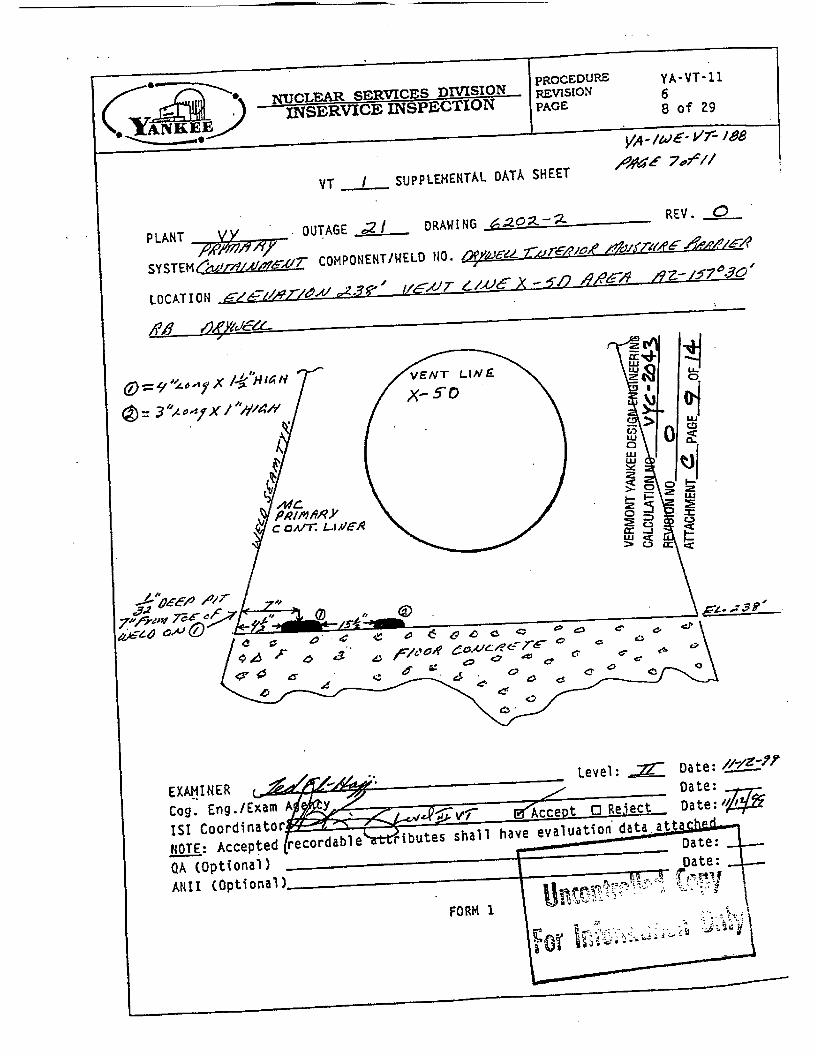
Evaluation of D w e l l shell at intersection of concrete slab El. 238.0’
During IWE examinations (Attachment C), a number of discreet locations with pitting and corrosion were noted. This analysis is performed to bound the areas of observed corrosion and to account for possible corrosion until a new seal and coating is applied. Observed pitting is limited to a total of 50 inches out of 1656 inches of circumference (about 3%).
This evaluation will consider that this corrosion exists all around the sphere and is considered 4 inches wide.
I DWG. 9-6202-005, the dimension between the 1.125 inch plates and the vent plates both the 1 inch and 2.5 inch is calculated to be:
I From Centerline of equater = 2.1615 + 20.1016 = 22.2631’
DWG. 9-6202-003, the centerline of equater is at Elevation 259.9167’
The elevation of the joint is 259.9167 - 22.2631 = 237.6536’ 1 I The elevation of corrosion is 238.0’ or about 4.25 inches above the joint between the 1
inch and 2.5 inch plates and the 1.125 inch plates below. ~

VY CALCULATION SHEET
THINNING AND SCREENING CRITERIA FOR ASME XI 1WE INSPECTIONS
Calculation Number wc-2043 Revision 0 PAGE & OF - T* EVALUATION OF PRIMARY CONTAINMENT LOCALIZED
PREPARED BY mB DATE /!/2//* REVIEWED BY DATE
DWG. 9-620241 1
The centerline of the vent on the outside surface of the shell can be calculated to be:
259.9167 - (31 .I354 sin 34.7428) = 259.9167 - 17.7439 = 242.1728’
The shell vent cutout is 8.5208’ in diameter so the elevation of the bottom of cutout is:
At elevation 238.93’ or about 11” above the corrosion area.
The actuat distance is along the shell at the outside surface is about 14 inches.
From previous page16, per Section N412(j), calculate the local stress area limits.
Location fo,, -m8an R 0.51Rt1°” 2.51RtS” - itevation 238 2.5 373.375 15.27 76.37
1 372.5 9.65 48.25
From previous calculation for General corrosion, page 15, the 1 inch plate between points 9 and 10 has plenty of margin. The calculation shows a -21 inch corrosion limit for these plates. The 2.5 inch plate is only affected by the vent in the area which is considered reinforcement. The other portion of the plate would be compared to the 1 inch plate which as stated earlier has about .21 inches of margin beyond the design required thickness. In the area of the vent, the reinforcement zone around the vent opening extends out radially for about 21 inches and will be intersected by the corrosion zone, however this only occurs for a small horizontal distance and the maximum corrosion reported is only .0625 inch deep pits (refer to attachment C). Considering the ,0625 and an additional allowance of 0.05 for one more operating cycle {total = .1125 inches). The ,1125 is 4.5 % of the total thickness which is not considered to be significant. Therefore the corroded area identified in Attachment C is acceptable.
++

VY CALCULATION SHEET r-- Tide EVALUATION OF PRIMARY CONTAINMENT L O C A U Z E THINNING AND SCREENING CRITERIA FOR ASME XI IWE INSPECTIONS
Calculation Number wc-2043 Revision 0 PAGE i!-g OF -
1.
2.
3.
4.
5.
SUMMARY / RESULTS
Minimum wall thickness and acceptance criteria for general wall loss due to corrosion and/or wear based on the original design report, reference 4, were developed for the Drywell shell and are shown on pages 14 and 15 of this calculation.
Generic evaluations of pittingisurface effects based on the original design report, reference 4, were performed. Small shallow pits and gouges are surface effects, and if there is sufficient space between them they will not effect the membrane stress in the shell at the pit location. Criteria for use in inspection and evaluation of surface pitting were developed. These are shown on pages 19 and 20 of this calculation.
A simplified method for evaluation of shallow localized wall loss less than about 20 percent of nominal wall thickness was developed. The method is based on the original design report, reference 4, and is in conformance with the original design d e and accepted engineering practice, The method is shown on page 21 of this calculation.
The TES methodology for future evaluation of localized wall loss was applied for the Drywell shell at certain locations. The TES methodology was developed for the Torus but can also be applied directly to the Drywell. The methods are outlined on page 22 of this calculation.
A bounding evaluation of corroded areas internal to the Dywell at the intersection of the concrete slab at elevation 238 feet was performed. This evaluation is intended to serve as an enveloping case for future evaluations and examinations in this area until the corrosion is mitigated. This evalulation is shown on pages 23 and 24.

W CALCULATION SHEET Calculation Number VYc-2043 Revision 0 PAGE 26 OF - ~ l l ~ ~ l l m h p r j - ~ i f ~ e EVALUATION OF PRIMARY CONTAINMENT LOCALIZED rHlNNlNG AND SCREENtNG CRlTERlA FOR ASME XI W E INSPECTIONS
V
ZEFERENCES
I. ASME Section 111 Nuclear Vessels, 1965 (with Winter 1965 Addenda) and ASME Section
2. Design Specification for Vermont Yankee Reactor Containment , No. 22A1265, Revision
3. Purchase Specification for Vermont Yankee Drywell and Suppression Chamber
V111, Unfrred Pressure Vessels, 1965.
No. I, by General Electric Nuclear Energy Division.
Containment Vessels, No. 21A5837, Revision No. 3, by General Electric Nuclear Energy Division.
$. Certified Stress Report, Vernon - II, Vermont Yankee Project Containment Vessel, No. 9-
5. ASME XI, Subsection IWE, Requirements for Class MC and Metallic Liners of Cfass CC
3. Stress Concentration Factors, by R.E.Peteson , published by John WiIey &Sons, New
7. Chicago Bridge &Iron Drawings for Vermont Yankee:
6202-11, October 29,1968, by Chicago Bridge & Iron -Oak Brook Engineering.
Components of Light-Water Cooled Plants, 1992 Edition with 1992 Addenda.
York, CopyWright 1974.
Number Revision m. 6202-001 1 Pressure Suppression Containment Vessel Arrangement & Field
Assembly. 6202-003 0 Fiefd Assembly of Drywell Shell
6202-005 0 Shop Details Drywell Shell Plates
.6202-011 0 Drywell Vent lnsert Assembly .
GI91529 1 Reactor Pedestel Concrete
3. WC-1032, Revision 1, Torus Shell and Vent System Thickness Requirements”.

VY CALCULATION SHEET
THINNING AND SCREENING CRITERIA FOR ASME XI IWE INSPECTIONS
Calculation Number vYc-2043 Revisbn 0 PAGE a OF - vNlb T i e EVALUATION OF PRIMARY CONTAINMENT LOCALIZED
PREPAREDBY R m m D B Y O A F l \ / d q ? I I
CONCLUSIONS ' General area minimum wall thickness and acceptance criteria for areas of localized corrosion Mere developed which are consistent with the original Design Report, reference 4 and ASME sode requirements, reference 1. These are summarized on page 25.
Revision of this calculation does not affect any other existing VY calculations, there is no change to the plant as described in the Final Safety Analysis Report, and no 50.59 screen or svaluation is required.
Jhis calculation will serve as a reference for evaluation of results from inspections of the Drywell Shell performed under ASME Section Xl, Subsection IWE. The inspections are performed under VY Program Procedure PP7024, "Containment Insenrice Inspection Program (WE)".

Page 28 of w CALCU~ATION REVIEW FORM
N/A Revision Number:- REVISION 0 CCN Number: Calculation Number: VYC-2043
Title: EVALUATION OF PRIMARY CONTAINMENT LOCALIZED THINNING AND SCREENING CFUTERZA FOR ASME xr IWE INSPECTIONS
K evie er Si ature \l./w/41 W
Method of Review: ~Calculation/Analysis Review - Alternative Calculation -Qualification Testing Date
*Comments shall be specific, not general. Do not list questions or suggestions unless suggesting wording to ensure the correct interpretation of issues. Questions should be asked of the preparer directly.
VYAPF 001 7.04 (Sample) AP 0017 Rev. 5 Pagc 1 of I

I
APPENDIX H
REVIEW CHECKLIST (ER 961090-01)
NIA any items not applicable to the calculation or CCN.
I .
2.
3.
4.
5.
. , . .
... PsqE 29
Requirement
Ensure the title page is properly filled out (items that are applicable).
0
e 0
e
0
0
0
0
0'
e
Calculation or CCN number on cover Title reflects subject Correct QA record status box checked Page numbering and count is correct Cycle number is'inctoded ("NA" if not appjicable) Initiating document is listed SSC I.D. numbers listed Vendor calculation and revision number listed Vendor safety class P.O. number listed Superseded calculations listed Keywords assigned Computer codes (inputloutput) listed Signatures and dates are Included and are in correct chronological order. The title page reviewer and approver dates do not predate other dates in the calculation
The following forms are properly filled 0-ut and attached {if applicable):
0 . Review forms VYAPF 001 7.04 (Ensure dated signaturesform the ,preparer and reviewer are included and all comments have been addressed)
0 Open Item Listing VYAPF 0017.05
0 Evaluation of Computer Code Use VYAPF 001 7.06
0 Calculation Database Input VYAPF 001 7.07 ,
Calculation Change Notice WAPF 001 7.08.
Ensure review of the calculation can be done without recourse to the originator.
Pren a rer Reviewer
Screening Evafuation/Safety Evaluation included.
Ensure individuals responsible for each portion of the calculation are identified when multiple preparers andlor reviewers are used.
Appendix H AP 0017 Rev. 5 Page 1 of 3

.,. . . 6.
7.
8.
9.
10.
I I.
12.
13.
14.
15.
16.
17,
7 8.
19.
Reauirement PreDarer
Ensure that the calculation contains a t m a g e , t a b k o f contents, calculation>ective,method of solution, desig3inputs and_sources, assumptions, calculation, &Its, -- conclusionzand references.
. _ . . ._ . . . ~ . - . .,. . . . . - .,. . i... .. , ... , .. . * . 1. .. . . .L _ _ . < : . . .
I- _.
Ensure that each page has a page number, calculation number, revision number and CCN number, if 'applicable.
Ensure that every page of every attachment {or Appendix) contains its attachment (or Appendix) number.
Ensure that the methods for revising and correcting the calculation meet the requirements of App. C of AP 001 7.
Ensure that the legibility requirements of App. D of AP 0017 have.been met.
Ensure thet the appropriate design inputs (e.9. QA records) were used and the source of these inputs are clearly referenced.
Ensure that the calculation design information, both external and internal requirements have been met..
Ensure that if design specifications were used as input to the calculation the. performance characteristics are independently verified and documented.
Ensure that all reviewers' comments have been addressed.
Ensure that input and modeling uncertainties are explicitly addressed ih the calculation. (ER 961090-02)
Ensure that any restrictions and/or limitations on the use of the calculation are cfearly stated.
, Ensure that computer codes are used in accordance with App. E of AP 001 7.
Ensuk that the applicable Input considerations from'App. C to AP 6008 have been incorporated and are explicitly addressed within the calculation.
Ensure review of 1 OCFR50.46 reporting requirements has been documented for analyses which assess conformance to 1 OCFR50.46.
Appendix H AP 0017 Rev. 5 Page 2 of 3
. .

..... .--.,... 3:.-, .*,: >. h. .... ...... :.-- . . ,.,"/. . . .: ........ ........ : . . : ,-- >\::..- . . . . . . . . . . . . . . . . . . . . r__i__ -:> ......... ............ ' ' 8 .... :. -
APPENDIX H (Continued) .Jyc - 294% &..w .a
$
Organization
Signature
?AC+i' 3 \ Preparer' Reviewer
Organization
Signature
Date
- I Date - ..
. . .
Appendix H AP 0017 Rev. 5 Page 3 of 3
. . . . . . . . . . ........ ..... . . . .
- .................. .......... . . . . . . . . . . . . . . . . . . . . . . . . . . ,__,; ~ :.
. .
. _ ? . . .

/ ' - .. i
,. . . , . I .. .- .
CHICAGO BRIDGE & IRON COMPANY
!.,. \
MEMPHIS ENGINEERING DEPT.
5G PSI
. . .

VERMONT YANKEE DESIGN ENGINEERING CALCULATION,NO uyd 204% .
AllACHMENT PAGE 2 OF 18
- RNlSlON NO b
.. - ...........
._
L
GO 6d O B

c
c- OAK BROOK ENGINE ERlNG
. . r G B d b 7
. . . .
4stoc -l.’
+ ‘ sb
. . . 4 0 S n ’
. . ..
. . . - . . rb : , : .-. --. . - -. - Y.
. . * . . -345q ; . . ’
. .+
‘ - c
S d f s’i 4+ - . . -
i


706 \ . . .
6- ea

c ..* ' . '- CHltAGO BRIDGE'& IRON CbrdPANY .
_. -. . -
. . -_ . . . ._ . . . . .
. .
c OAK BROOK ENGINEERING
VERMONT YANKEE DESIGN ENGINEERING CALCULATION NO \n(co -4'3 REVISION NO 0
A~ACHMENT A PAGE&OF&,
. . .
ii . _, :
L
GO $4'06 Chsckod b y _ ' ' ' Date "'-.". ' Rev No -Date ROV N o -Date

. . . . . . .
R ...*
* CHICAGO 6ElDCE b iRON M A N Y
.'.., . .- . .
. I
- OAK BROOK ENGINEERING . . c
VERMONT YANKEE DESIGN ENGINEERING CALCULATION NO vyL-2643 REVISION NO 0
ATTACHMENT A P A G E ~ O F ~ ,
..
. . . .
I1596
--_. ......... ..___ ._._.__L-I.I ........... ---.- ........ . . - .. -. --- .. -. ............. - ..-- --- -_^ - . - - . - . - . ........ ' - "~CUtAFERENTlAL STRESS . - .. ~ ClRCUhPl FE2ENTIP.L STRESS . _: .:. __ .__. - .
...... ........ . . . . . . . . - . -.-.-. ..__.*.__ .-_ .__... I -.. -.-- ----..- -- . . . . . . . . . . .... . . . . . . . . .... .... . . _ - .. -_ _.-.- - - - . . . . . . . . ... (Oiii5j PSI "(INS) -.- I. ,..._-_.-. ..--. .- .-. -
,

OAK BROOK E N G I H E E R I S Q
. '
' VERMONT YANKEE DESIGN ENGINEERING ' CALCULATION NO VYC Z d - 3
ATTACHMENT A PAGE S OF 1%
\ REVISIONNO 0
452067 '
I
00 6 4 0 8

.. . . -. __ . . . . , . . - .
CHICAGO BRIDGE & IRON COMPANY
. .
OAK BRCfOK ENGIN-EERING

. - . * _ . 1 5 4 4 4 - z - J \

. . . . . , . . . _. . -
Stresses w e r e found using the Kalnin's' program as published i n the Journal of Applied Mechanics and an internal pressure o t t p s i .
using the temperature gradient
1 4 - e Spring constant of sand = L i
where A P = increase i n pressure on sand (assume 80 p s i ) e = initial void ratio (assume . 8 )
L:= thickness of sand layer normal to shell at point be - change in void r a t i o (0.035' from f i g . 3 i n reference)
--A
considered
Spring constant o f sand @ A = 202.71 FS!,.,;,,
Spring constant o f sand @ B = 5'Ei?,23 p?&
*'rS'Stresses i n Cylindrical Pressure Vessels Partial Supported by Soil" i , . t - '
(ASME Paper No. 53-A-82)
-L

.. . . .. , . . . . , . . . . .. . . . .. . - .
CHICAGO BRIDGE & IRON COMPANY
- _a - .L
1/1/68 . OAK BROOK ENGlNE €RING
c VERMONT YANKEE D SIGN ENGINEERING CALCULATION NO 5YL- 2&3
ATTACHMENT A PAGE 12 OF l g RNlSlON NO 0

VERMONT YANKEE DESIGN ENGINEERING
REVISION NO ATTACHMENT A PAGE \ 5 OF I g
CALCULATION NO VVC I 2&3
EQUATOR -.- ELEV, L 259 '-1 "
5EkfA h €LEV.= 2 5 7 ' - 9

I'
. . . . . . . .
. . .
(c . . CHICAGO BRIDGE 8 IRON COMPANY MEM P H I 5 EN GIN E ER 1 N G DE PT .
... . . .... VERMONT YANKEE DESIGN ENGINEERING ' '
> .
- b
_:. - .
CALCULATlON NO 2643 . . . - .. REVISION NO . .
c ; . , . . . . . . . . . . . . . . . . . . . .;.
. . . ATTACHMENT PAGE /&OF ' . , .
i .- -:
. . . . . . . . . . . .
. . . . .
.....
. . . . . , . ~.
. . . . .
. . .
. . . . .... - ..
._ . ~ . . ......... . . * . . _ ,---. -
cu 9 I
3 E
fi 0 0
". 1 .:'
4 '
I -1 . -
I

CHICAGO BRIDGE & IRON COMPANY
'C : 1
.... . . . . .
i.
\. l' c
. .
... .
. . . .
I'
. . .
c VERMONT YANKEE DESIGN ENGINEERING . CALCUV\TION NO VYC - 2043 . ..
. REVI~ONNOQ -. AVACHMENT A PAGE,JSOFXL . . - .
? . S - ,.. -3 -J %. 3 > a * - I
MEMPHIS ENGINEERING DEPT.
c .
-- _]

.... ._. . . . . . . . . . . .
4
. . . . . CHICAGO BRIDGE 8, IRON COMPANY MEMPHIS ENGfNEERlNG DEPT. .....
. VERMONT YANKEE DESIGN ENGINEERING . , ."
ATTACHMENT' A' 'PAGE Ib OF I8.
. . . . . . i : * . , . - . . . . XALCULATIOI~~O dYc-2043. .
r - ,
. A . . . . . . .
. . . . . . . . . < . ! ' , . . 'REVISIONNO . - "' 0 '
. . . . . . . . . . . : . . ..+ 1 - .
. . . . Y :. . . .....-. . . . . _ .
I 6 -
I
. . . . .
I
- i
---
. .
. . . . . . . .
- .
. .
. .

. . . . . . . . . .c .. * C ' ' L
. . . . . .
. MEMPHIS ENGINEERING DEPT. . . . . . . . . . . . .
. 8.
: CfilCAGO BRIDGE & IRON COMPANY . _ : . . .
. .
. ....
. . ... .- . . . . . .
_.
. . - _ . _ ..... I..-
..--.. . . . ..... . . . . . . . . 1.. .-
. _ . . . . . .
... ! . . ...... . ...-.
. .- . . . . . . . .
...... :. .... .......
. . --. . . . . _ . . . _ . ;; .. , .
. . . .
. . . . . . * - .
. . . . . Z . . '. -
. .
- .

r
OAK BROOK ENGINEERING 3 , c
--c - CHICAGO BRIDGE & IRON COMPANY
I
- VERMONT YANKEE DESIGN ENGINEERING CALCULATION NO ~/y~-2&3 REVISION NO 0 AITACHMEM A PAGE Ig OF I 8
.

VYC-1032 ATTACHMENT B
CALCULATION PACKAGE 7426-1
APPENDIX 8 , .
PERM f SS I BLE INDICATION SIZE CALCULATIONS
The general calculations contained in this appendix consider the dis- continuity effects resulting from a localized indication t o determine the range of permissible indication sizes i n the presence o f general membrane stresses for Class MC pressure vessel.
. . . . B.1 and 8 .2 use the general results t o specifically address the torus -
. shell and vent system . . range o f permisslble indication sites.
*
. .
.. ' ..
. . . . .
! .
. f
. . . . . . . . . _-..... . . . . . . . . . . . . . .... .. . . . . . . . . . . . . . .
. . . . . . ... ... .. l _ _ . -. . .
. i .- ~ ,.-
. .
, . . - .

* . 1 . . . . . . . . . . . .
..
i

v Y c-1032 ATTACH ME NT SERVlCEs;
8
f I ; I 2
. . ; t
. . . -
. . -/ . .
- .
. . VERMONTYANKEE DESIGN ENGINEERING , . , . : CALCULATION NO '. V YC .z 2043..
-
. . - REVISIONNO ' 0
..-: __.-__ ._._ -ATTACHMENT h .PAGE 5' OF It-'---- -- . . _ .
. . . .
..
. . . . . . . . . . . . .- - . . . . . . . . . . . . . . . . . . . . . . . . . . . * . .
dW/& A=, ';A 1 , k , 'A"'& &9.- .. - . , *
. . . . . . . . . . ----P.--.----- --- IC..--- . - .- . . . . . . .... t . . . . . . . t
: ' - - . a . . . ,.. 1 . . . . . . . . . ;
. . . . . . . . . . . . . .
. t . - . . . . . . . . . . . . . . i-.- - . . . . - .
. . .-
. . .
- . . *.
. . .
- .-. . . . . . . .. J v A r r L
qj.-
6, =
' .
* *
&. 7 6 . . . ...... .....
&
i -' .
....... . _._a__. . . - ... _. -. ..... ._ .
. . . .

. .
. .
. .
* . . .
-,.f- .
. . . ..". . . . . . . . . . ... .......e. . . . . . . . @. = * .8.,,
-. . . . . . . ..*.I . or
* I . , . k / ' . . . . A / / b , :
r . , . _ . . . . . . . . . . . . . . . . . . . . . . . . . . . . . . . * . . . f 4 J - . .
. . . . . - - .
. . ...
. . . . . . . . . . . . . . . !. - * I
'i . . . ... I . . .
.............. *.
......... .*e-.- -- . .
* - [ e ) . . - .
. . . . . . . - . . . . . . - .
. . . . . . . . . . . . . . . . . . . . . . . . . . . . 8 ..... -- ~ . ... :.
. . . . . . . . . . .. . . . .

VYC-1032 ATTACHMENT B
I
- . :
. . . ... _._-I -..--. ......... - C.I .-- .- . f .
. - . -. I. r
6 / i , -d) / .T. . (5). - 3 ' * L .
r . - . .
.... ... . . .
. .I I .. - -. * e.- . . . - .---------
. . . . . . . ." . . . . . . .
...
. .
,/' . ,;

- ... ..- . -
.. . . . .-.
r . ' 1 0
$4' b" ru
- . .. .
.. .. . . - - .
. . . . .. . . _- ...- .... .e-. . -

. .
,i
...-.
. .

VYc-1032 ATTACHMENT B
. . a . ...QTd. . . . 1
. . . . ... .-..----I--* .........
P . . . . .
. . . . . P .-. . 3
. . . - . e . .
....
.... ... - ...
. . .

. *
. . ;.:..i :.' ..
-t
083 . . ....-. . -. .. .....
- 0 , f
: 0.3 . .
. . . . . . . . : ": . y f.0 ... : . '''-'a ... I. ...... ..- ........ ...... -*.... . ..-- ... -1
3 , y 1 3.-; I--.. /FQ-CKTC'ZV7B : . - t . . . . . . ..e* a . . . /. 1 0 0 .................. I , f 04-, : a,035s: ; . . . . . ... . . . . . . . . . 2,707. ............. --. . . . .
2, LIL J , 13 6' ,:O:;O.Y97i*: :: IJ . .. ..- - . - I---- .~
... : - . . . . . . . * . I . .
-- -.. - . . . .......
. . . . . . .... --. -.
..... ./- , l 7 . . .... -. ...2.;f._.-?. ... -;. . . ........ - .. . . i -.
, . * . . . ,

- - , VYc.1032 ATTACH ME NT E
7a'TEtEDYNE ENGNEEBNGSERVCCES
. . . . . . . . . . . . . . . . . . . . . . . . . . . . .
. . . .. .i . . . .I_.._.. .....
.. - . . .-.

. .
. . . .
. i . . - . . . . i I
I , 0
0. ci . .
0. s
0.3
. . . . . . . . . . ..- - --. - _.-- - ... -.-- --- . . . . . . . 0.334 . 0,4% - i : . .
27.t7-7 . . .DiLgy: ::; . . .
;#JZ. ..A!*. . . C?.l% ._ : .. ) . . . . .
. . . . . . . . . . . . . . . . . . . . . .. . . . * . . . . . . . . . t * *.
. . . . . . . . . . --~ __.__.-.- - ...... C-. ..... . . ----I^ ... .: ... . - . . .-b.. . .
- * . . . . . ' . . .? . . . . . . . . . I . . . . . . 1 - . . . . . . . . . ..- . . . . . .
. . O,Y
6, I
6, 2
/A 3
/ I37t3
..... -..
..
........ 4.. ....- ...... . . . . . . . . . . . . . . . . . . . . . . . -.. ... i . . . . . . . --- --.---- . . I ' . I._L--.-. e"-.--- . . . . , . . . . . . ! ........... ! , .&... . . . . . . .
. . -
. . . . . . . . . ; . . . ........
. I . . . . ...... . . . .
. . . . . : . . ....
.......... 6 . . . . ? ' . . . . . . . . . . . . . . . . . . ! . : " . . . . . . . .-e ..
. . . . . . . . . . . .
....... ..!: . . . . . . . . . . . . i . . . . . - :
8 " ......... r . . . - . I . . .
. . . ..; . . . . . . - * } . . . . . L
! * - * - . " f . ..*. . -. -.--.-.- ! ....... -._...e- ". . . . : . . .* .
. . . -... .. -- .....
. . . . . . . . . . . . . . . . . . . . . . . . . . . . . . . . . . . . . . . .
/+ .- . . . . . . . . . . ... ... . ... - . . . . . . . .- - ._ . . . .- - .- -. ,: .--.--e ._: .; . . . _ .. . . . . ..- . - ... --.- ..-1 . . . . . . . . . . . . . . . . .

. . . . -. .i .
.....
0, Y .... . .
. 0.L . --- . . . .
.-. ....
. . .
i* . .- .
. . . -.--c- . * . - * ........ . . . . . . . . . ........--...--.-----
. . . . . . . . . . . . . . . . . . ....... - . . . . . . . ....... . . . . . . . . . . . . . . .
... . . . . . . . . . . . . . . .
..... :.. . . . . . . . . . . . . . . . . . . . .
. . . . . . . . . . . . . . . . . . . . ....... . . .. . . - .,e- .--.----.--- -
- . . . . . . . . . . * : . - * \ : . . - : * _ -
I .
' d ....... . . . . . . . . . . . . . . . . . . ..... ................ ............. . . . . . . . . . . . . . 0 :.--- - :. .: -. -.:. L ..-.. ---. - .i=- ..=. :::-: . .
. . . . . . . . . . . . - . . . . . .

I
0 P h s t e a l Damage o r Oisplccenent Deirls Pat n t 81 i s t e r i ng
0 Paint Flaking or Peellns 0 D I s c o l o r a t i on Corrosion
/ a Erosion D 0
/n&rAL C9#uL'' 49s 12,flfl'JZ
/
Y f - 1 O R VT-3 EXAHIHATIOH OF
Cracks 0 P l t t i n g 0 Arc S t r f k e s 0 Gouges or Dents 0
a YT-1 u V I - J
Other Surface Oiscont inui t fes Ph sfcal Damage o r Oispltcenant
13 a Wear D i scot o r a t i o n 0 Excessive Corros l on 0 Erosf on Other
Degrfs 0
u PEMARKS ddA&de * N-6-99
V e e r c3 Damage t3 E r o s l on 0 Tears (3 Surface Cracks fl 0 Other
c_I_ REMARKS JO&C S€. / /-A 99
SUPPLEHEHTAL OATA SHEET ATTACHED: &s D KO
,
Level: /. Date: Date: A42422 ' v1 0 ACCeDt d P . e i % c t Date: 1-
t tr ibutes s h a l l h:ve evaluat ion d a t a attached. Date: -- Date: ,-
- QA (Optional) AH11 (Optional)
FOLY 6-2

NUCLEAR SERVICES DMSION INSERVICE INSPECTION
.-.
VERMONT YANKEE DESIGN ENGINEERING CALCULATION NO vlfLCz443
AllACHMENT c PAGE 2 OF 14 REVISION NO 0
Y A - V T - 11 PROCEDUriE
PAGE 6 a o f 29
Leve l : Date: /!-i6-99 D E te :
h a l l have e v a l u a t i o n d a t a z t t a c h e d . Q A ( O p t i o n a l 1 D z t e : ANI I (Opt i ona 1 1 Date:
El Acceut 6 j e c t Ozte: t t , h / S
FORM 1

NUCLEAR SERVICES DMSION WSERVICE INSPECTION
VT-I OR VT-3 EXAHIHATIOH OF COATEO SURFACES VT-1 IJ V I - 3 u Cracks Ph sical Damage o r Ofsptacement 0
P a i n t 81 i s t e r i n g cl P a i n t F lak lng o r Peeljng 0 Disco1 o r a t i o n 0 Corrosion Eros ion 0 Other n U
DeEri s 0
REMARKS &AC,/€ // - 99 , . - 2 1 7 W
VT-1 OR VT-3 EXAHIHATIOH OF NOH-COATED SURFACES Accept Kecoragabie
H# V T - 1 7 VI-J n Cracks P i t t i n g II D Arc S t r i k e s 0 0 I Gouges o r Dents I 0 0 Other Surface D lscon t inu i t i es I 0 Ph s f c a l Damage o r Oisplacement 0 I 0 Oegris 0 n Uear a c1 0 i scol ora t i on 0 c3 Excessive Corrosion U I Erosion 0 0 m . Other 0
rF: &!fi~/s^0Aur r/& S- ,swb&pr/& A m w /%?%we c~,Q&M/A& REMARKS 5s.c P?r4’ a ,- 92- //
0 A&. //-/z-94. t
y k /rJE- H7-J.8 YA-VT - 11 6
PROCEDURE REVISfON PAGE
16 o f 29
REMARKS
Seals Gaskets and Ho ls tu re B Wear Oama e Erosyon Tears Surface Cracks
I 1 SUPPLMEHTAL DATA SKEET ATTACHED: YES 0 80
//-A249 Level: Z I
L + e l v r W A C C e p t CY Reject - HOTE: Accepted @ m d a b l f r i b u t e s shall have eva lua t i on data attached.
Date Oate Oate
Date Oate

._ - . . . . .
ISJ Coordinator,- /a
FORM 1

yA - /LJK 47- /a, PROCEDURE YA- VT- I f REVlSfON 6 PAGE 8 o f 29
p ? & A 3 o f // VT I SUPPLEMENTAL DATA SHEET
.
0 RWlSlON NO ATTACHMENT & P A G E - ! ~ - o F . ~ -
Cog .. Eng . /Exam A IS1 Caordinato

VERMONT YANKEE DESIGN ENGINEERING
REVISION NO
ASTACHMENT c PAGE (=, OF 14
CALCULATION NO uyc-243 CY
I ! _ .

I ? -

VERMONT YANKEE DESIGN ENGINEERING CALCULATION NO qyL 264-'3, REVISION NO 0 ATTACHMENT c FAGE.-B.OF&

YA- /&E- V 7 - 188 VERMONT YANKEE DESIGN ENGINEERING P&F fY// CALCULATION NO qyc d2043 REVISION NO ATTACHMENT c PAGE !Q OF !4
0

. . , , . .

VERMONT YANKEE DESIGN ENGINEERING CALCULATION NO vyL ATTACHMENT c PAGE 1% OF 14 REVISION NO 0

L.' :I' 1. ... . - ( - . I .. -. ' . .--: . I f ... ; e . ,
.~ I !
.- . 4_ : .I.> . ._:? ._ . .. . . . . e . .
PROCEDURE Y A - V T - 6 11 WJCLEAR SERVICES DMSXON ~ ~ S I O N
0 o f 29 INSERVICE INSPECTION PAGE
yA- /LJ& -vr-/e8 VT I SUPPLEMENTAL DATA SHEET /?-?-4g/@ef //
IS1 Coordinato

. C . . .:. ..-- _- . -
NUCLEAR SERVICES D M S I O N PROCEDURE
,-. PROCEDURZ Y P . - U T - I 1 2 6 EwSION
PAGE . 6 o f 6
SKETCH WITH RESULTS: