Calculation sheet - Elect
65
short - circuit current cal 1- Isc at secondary terminas of a HV/LV distri I sc = In / Usc where Isc : short circuit Fault cur Usc : Short-Circuit Impedance Voltage Of Transforme In : Nominal current In Am In : Nominal current In Am In = P ( KVA )*1000 / U20 U20 : Secondary Volts At Open Circu transfomer rated power (KVA) 50 transfomer current Ir (A) 69 oil - immersed transformer Isc (KA) Psc = 250 MVA 1.71 Psc = 500 MVA 1.71 cast - resin transformer Isc (KA) Psc = 250 MVA 1.14 Psc = 500 MVA 1.14 tables H1-33 : Isc at the LV terminals of 3-phase HV/LV tra * Note case of several transformers in parallel feeding a bu e of Isc can be estimated as the sum of the Isc from
-
Upload
sardarmkhan -
Category
Documents
-
view
220 -
download
7
description
Calculation sheet - Elect
Transcript of Calculation sheet - Elect
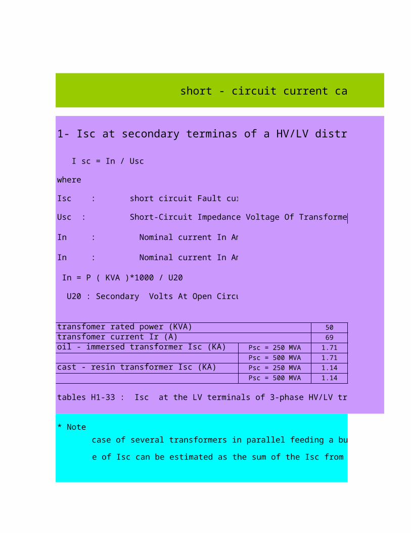
short - circuit current calculation
1- Isc at secondary terminas of a HV/LV distribution transformer
I sc = In / Usc
where
Isc : short circuit Fault current In Amps . Usc In %
Usc : Short-Circuit Impedance Voltage Of Transformer In % KVA 50 - 630
In : Nominal current In Amps . 800-2500
In : Nominal current In Amps .
In = P ( KVA )*1000 / U20
U20 : Secondary Volts At Open Circuit.
transfomer rated power (KVA) 50 100
transfomer current Ir (A) 69 137
oil - immersed transformer Isc (KA) Psc = 250 MVA 1.71 3.40
Psc = 500 MVA 1.71 3.42
cast - resin transformer Isc (KA) Psc = 250 MVA 1.14 2.28
Psc = 500 MVA 1.14 2.28
tables H1-33 : Isc at the LV terminals of 3-phase HV/LV transformers supplied from a HV system with a 3-phase faults level of 500 MVA,or 250 MVA at 420 V no load voltage
* Note
the case of several transformers in parallel feeding a busbar
the value of Isc can be estimated as the sum of the Isc from each transformer calculated separately
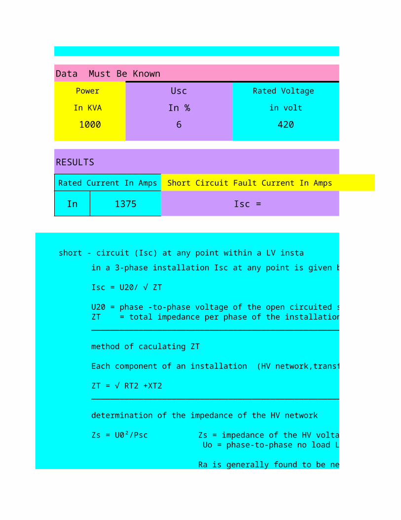
Data Must Be Known
Power Usc Rated Voltage
In KVA In % in volt
1000 6 420
RESULTS
Rated Current In Amps Short Circuit Fault Current In Amps
In 1375 Isc = 22.91
3 - phase short - circuit (Isc) at any point within a LV installation
in a 3-phase installation Isc at any point is given by
Isc = U20/ √ ZT
U20 = phase -to-phase voltage of the open circuited secondary , windings of the power supply transformers ZT = total impedance per phase of the installation upstream of the fault loctin (in ohms) ______________________________________________________________________________________
method of caculating ZT
Each component of an installation (HV network,transformer, cable,circuit breaker,busbar, and so on …. )
ZT = √ RT2 +XT2______________________________________________________________________________________
determination of the impedance of the HV network
Zs = impedance of the HV voltage network,expressed in milli-ohms
Ra is generally found to be negligible compared with Xa
Zs = U0²/Psc Uo = phase-to-phase no load LV voltage, expressed in volts.
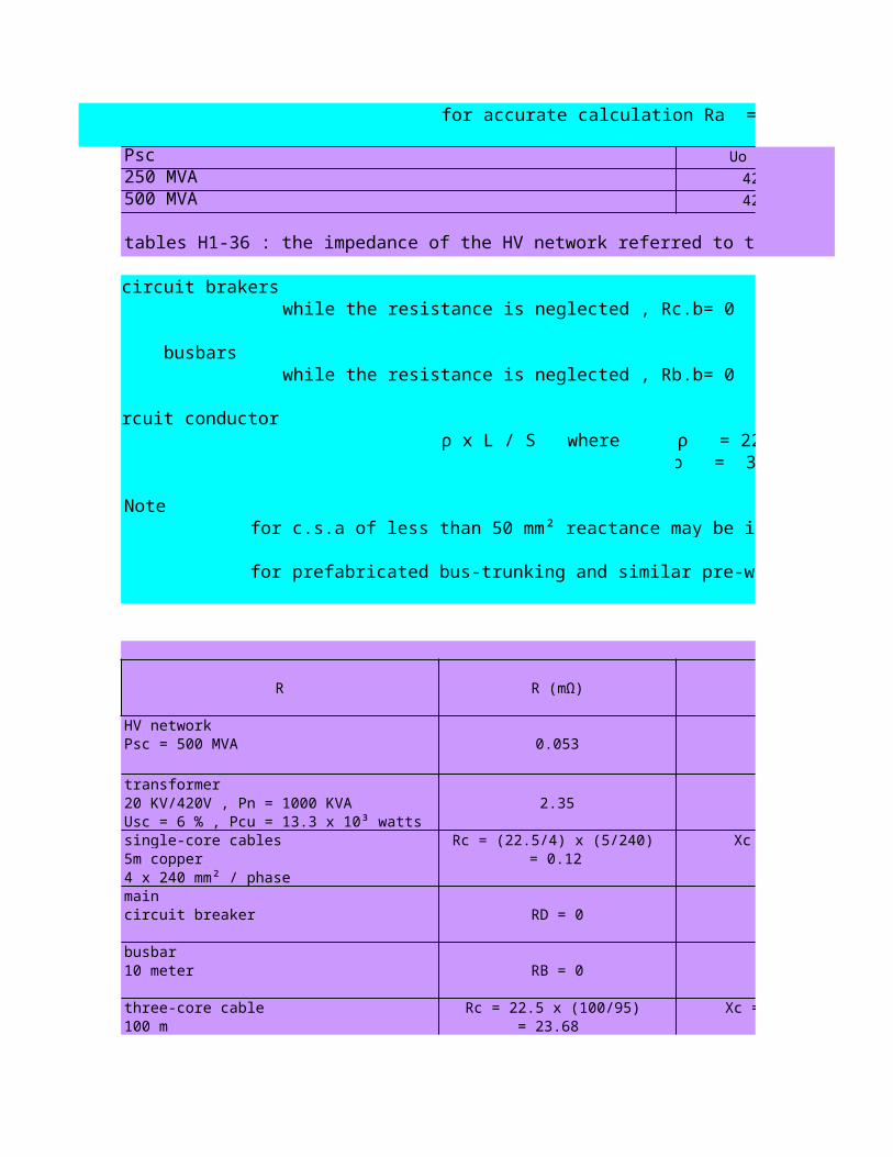
for accurate calculation Ra = 0.15 Xa
Psc Uo (V)
250 MVA 420
500 MVA 420
tables H1-36 : the impedance of the HV network referred to the LV side of the HV/LV transformer
circuit brakerswhile the resistance is neglected , Rc.b= 0 , Xc.b = 0.15 m Ω per circuit breaker
busbarswhile the resistance is neglected , Rb.b= 0 , Xb.b = 0.15 m Ω per meter length
circuit conductors Rc = ρ x L / S where
Note Xc =0.08 m Ω / m for 50 HZ system Xc =0.096 m Ω / m for 60 HZ system
for prefabricated bus-trunking and similar pre-wired ducting systems, the manfacturer should be consulted .
R
HV networkPsc = 500 MVA 0.053 0.353
transformer20 KV/420V , Pn = 1000 KVA 2.35 10.34
single-core cables Rc = (22.5/4) x (5/240) Xc = 0.08 x 5 5m copper = 0.12 = 0.40
maincircuit breaker RD = 0 XD = 0.15
busbar RB = 0 XB = 1.510 meter
three-core cable Rc = 22.5 x (100/95) Xc = 100x 0.08 100 m = 23.68 = 8
ρ = 22.5 m Ω .mm ρ = 36 m Ω .mm
for c.s.a of less than 50 mm² reactance may be ignored
R (mΩ) X (mΩ)
Usc = 6 % , Pcu = 13.3 x 10³ watts
4 x 240 mm² / phase
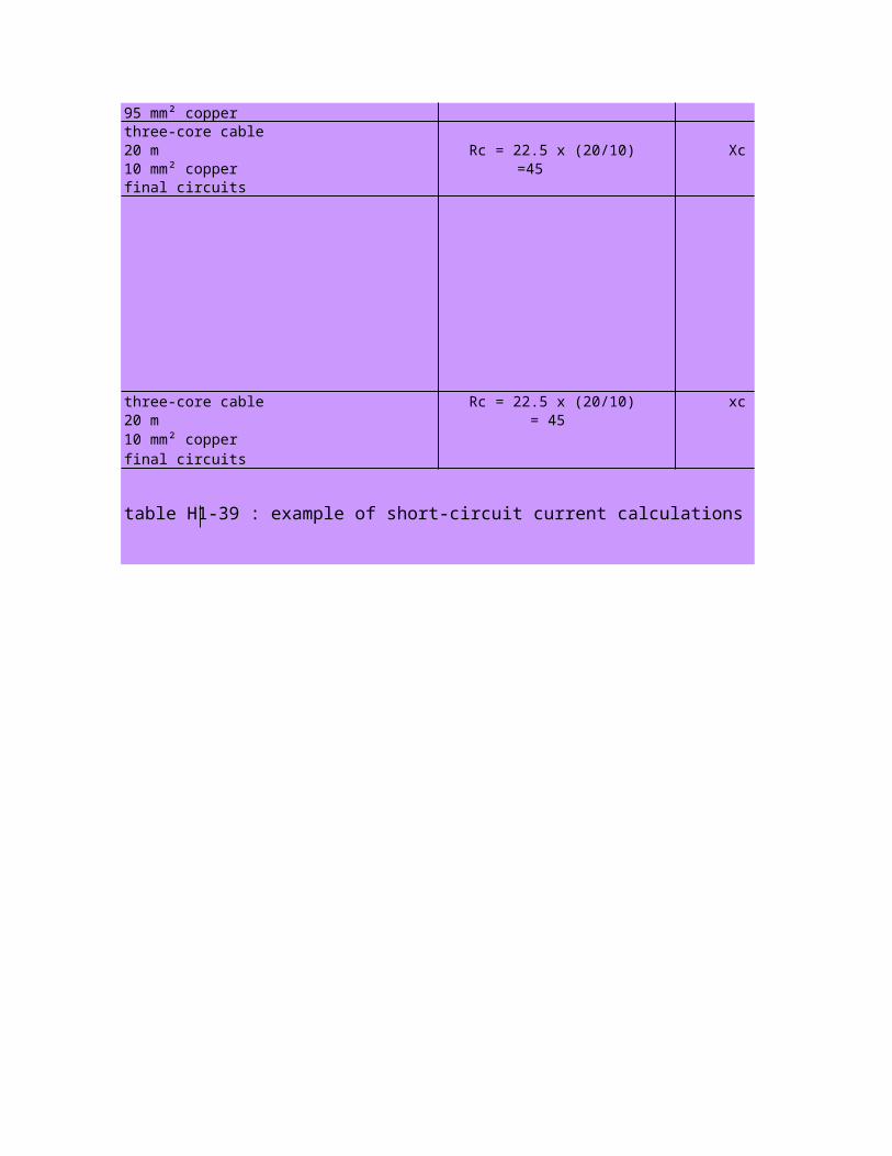
three-core cable 20 m Rc = 22.5 x (20/10) Xc = 20x 0.08
=45 = 1.6final circuits
three-core cable Rc = 22.5 x (20/10) xc = 20x 0.08 20 m = 45 = 1.6
final circuits
table H1-39 : example of short-circuit current calculations for a LV installation supplied at 400 V (nominal) from a 1000 KVA HV/LV transformer
95 mm² copper
10 mm² copper
10 mm² copper

short - circuit current calculation
1- Isc at secondary terminas of a HV/LV distribution transformer
I sc = In / Usc
Usc In %
oil Cast-Resin
4 6
6 6
160 250 315 400 500 630 800 1000 1250 1600
220 344 433 550 687 866 1100 1375 1718 2199
5.41 8.38 10.5 13.2 16.4 20.4 17.4 21.5 26.4 33.1
5.45 8.49 10.7 13.5 16.8 21.0 17.9 22.2 27.5 34.8
3.63 5.63 7.07 8.93 11.1 13.9 17.4 21.5 26.4 33.1
3.65 5.68 7.14 9.04 11.3 14.1 17.9 22.2 27.5 34.8
tables H1-33 : Isc at the LV terminals of 3-phase HV/LV transformers supplied from a HV system with a 3-phase faults level of 500 MVA,or 250 MVA at 420 V no load voltage
the value of Isc can be estimated as the sum of the Isc from each transformer calculated separately

Short Circuit Fault Current In Amps
22.91 KA
windings of the power supply transformers ZT = total impedance per phase of the installation upstream of the fault loctin (in ohms) ______________________________________________________________________________________
Each component of an installation (HV network,transformer, cable,circuit breaker,busbar, and so on …. )
______________________________________________________________________________________
Zs = impedance of the HV voltage network,expressed in milli-ohms
Ra is generally found to be negligible compared with Xa
= phase-to-phase no load LV voltage, expressed in volts.

Ra (m-ohm) Xa ( m-ohm)
0.106 0.71
0.053 0.353
tables H1-36 : the impedance of the HV network referred to the LV side of the HV/LV transformer
while the resistance is neglected , Rc.b= 0 , Xc.b = 0.15 m Ω per circuit breaker
while the resistance is neglected , Rb.b= 0 , Xb.b = 0.15 m Ω per meter length
Xc =0.08 m Ω / m for 50 HZ system Xc =0.096 m Ω / m for 60 HZ system
for prefabricated bus-trunking and similar pre-wired ducting systems, the manfacturer should be consulted .
COMMENT
0.353 Ra = 0.15 Xa
10.34
Xc = 0.08 x 5 2.523 11.1 Isc1 = 21.3 KA
Rc = ρ L / S
RD = 0XD = 0.15 XD = 0.15 Per Circuit Breaker
XB = 1.5 2.523 12.75 Isc2 = 18.6 KA RB = 0
Xc = 100x 0.08 26.2 20.75 Isc3 = 7.24 KA
Rc = ρ L / S
ρ = 22.5 m Ω .mm ² / m for copper ρ = 36 m Ω .mm ² / m for aluminium
X (mΩ) RT (mΩ) XT (mΩ) Isc = 420 / √3 * √ ( RT² + XT² )
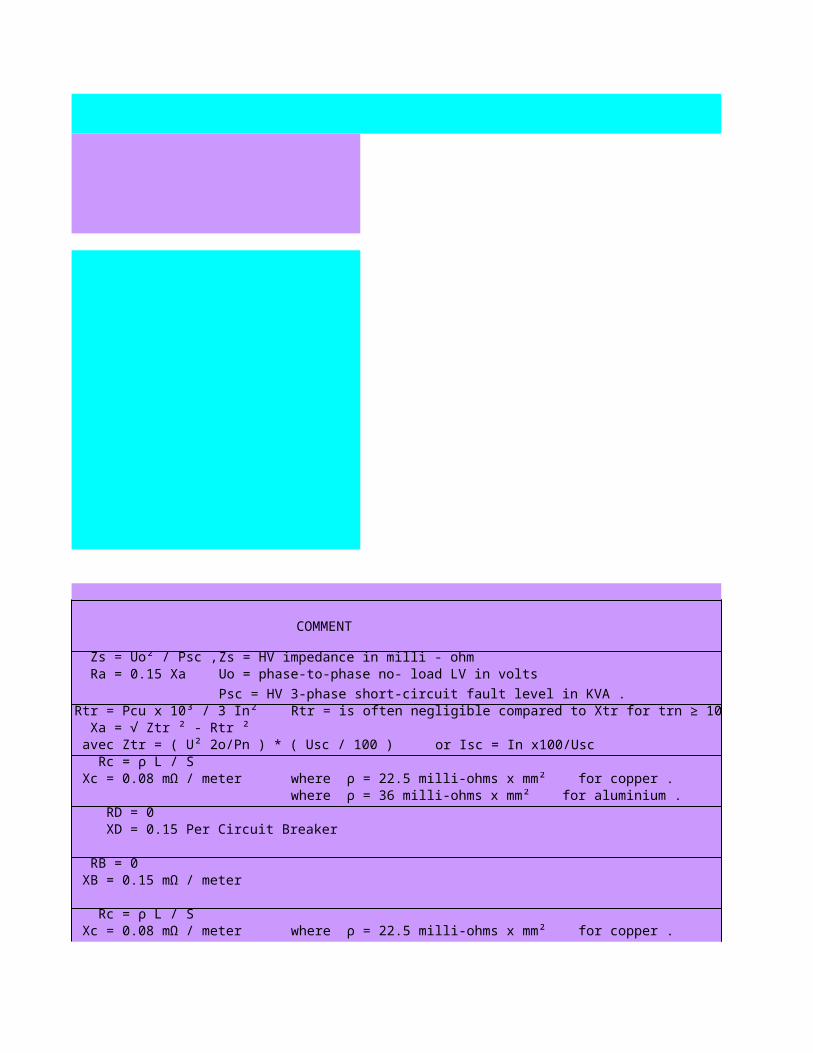
Zs = Uo² / Psc ,
Rtr = Pcu x 10³ / 3 In² Xa = √ Ztr ² - Rtr ² avec Ztr = ( U² 2o/Pn ) * ( Usc / 100 )
Xc = 0.08 mΩ / meter
XB = 0.15 mΩ / meter
Xc = 0.08 mΩ / meter

26.2 20.75 Isc3 = 7.24 KA
Xc = 20x 0.08 71.2 22.35 Isc4 = 3.24 KA
Rc = ρ L / S
xc = 20x 0.08 71.2 22.35 Isc4 = 3.24 KA
Rc = often negligible for S ≥ 200 mm² in the formula below
table H1-39 : example of short-circuit current calculations for a LV installation supplied at 400 V (nominal) from a 1000 KVA HV/LV transformer
Xc = 0.08 mΩ / meter
R = ρ L / S Xc = 0.08 mΩ / meter

2000 2500
2749 3437
40.4 49.1
43.0 52.9
40.4 49.1
43.0 52.9
tables H1-33 : Isc at the LV terminals of 3-phase HV/LV transformers supplied from a HV system with a 3-phase faults level of 500 MVA,or 250 MVA at 420 V no load voltage
tables H1-36 : the impedance of the HV network referred to the LV side of the HV/LV transformer
COMMENT
Zs = HV impedance in milli - ohmUo = phase-to-phase no- load LV in volts
Psc = HV 3-phase short-circuit fault level in KVA .Rtr = is often negligible compared to Xtr for trn ≥ 100 KVA
or Isc = In x100/Usc Rc = ρ L / S
RD = 0 XD = 0.15 Per Circuit Breaker
RB = 0
Rc = ρ L / S TRN1TRN2
Rtr = Pcu x 10³ / 3 In²
avec Ztr = ( U² 2o/Pn ) * ( Usc / 100 )
0.08 mΩ / meter where ρ = 22.5 milli-ohms x mm² for copper .where ρ = 36 milli-ohms x mm² for aluminium .
0.15 mΩ / meter
0.08 mΩ / meter where ρ = 22.5 milli-ohms x mm² for copper .

Rc = ρ L / S
Rc = often negligible for S ≥ 200 mm² in the formula below
CABLE1CABLE2CABLE3
CB1CB2CB3CB4
B.B1
B.B2
DATA
Uo (V)230
where ρ = 36 milli-ohms x mm² for aluminium .
0.08 mΩ / meter where ρ = 22.5 milli-ohms x mm² for copper .where ρ = 36 milli-ohms x mm² for aluminium .
0.08 mΩ / meter

230230230230230230230230230
(1) determination of the impedance of the HV network
DATA RESULTS COMMENT
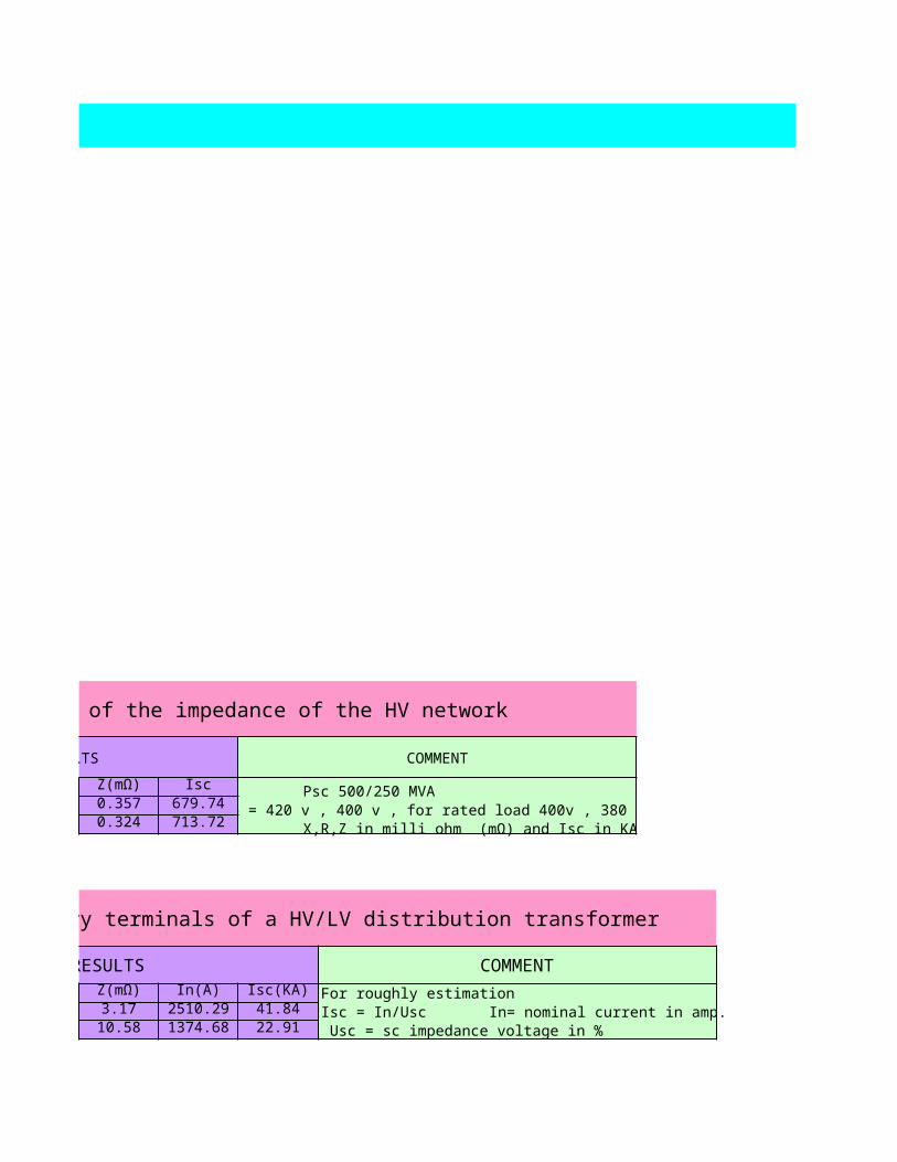
Psc Uo X(mΩ) R(mΩ) Z(mΩ) Isc Psc 500/250 MVA500 420 0.353 0.053 0.357 679.74 Uo = 420 v , 400 v , for rated load 400v , 380 v 300 400 0.320 0.048 0.324 713.72 X,R,Z in milli ohm (mΩ) and Isc in KA
(2) determination of Isc at secondary terminals of a HV/LV distribution transformer
DATA RESULTS
Pn(KVA) Uo(V) Usc(%) Pcu(W) X(mΩ) R(mΩ) Z(mΩ) In(A) Isc(KA)1000 230 6 15 2.47 1.99 3.17 2510.29 41.841000 420 6 13.3 10.1 3.22 10.58 1374.68 22.91

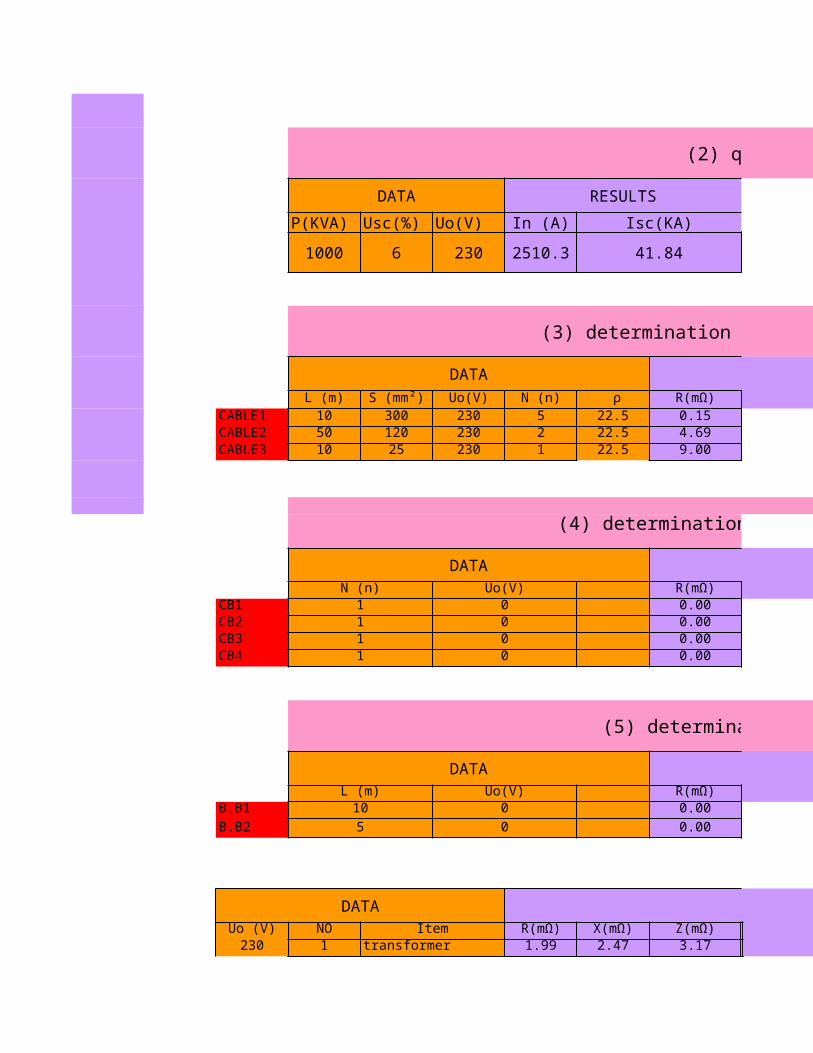
(2) quick estimation
DATA RESULTS COMMENT
P(KVA) Usc(%) Uo(V) In (A) Isc(KA) Usc = 6 % for 800 to 630 KVA
1000 6 230 2510.29 41.84Usc = 4 % for 50 to 2500 KVA
(3) determination of Isc for low voltage cables
DATA RESULTS
L (m) Uo(V) N (n) ρ R(mΩ) X(mΩ) Z(mΩ) Isc(KA)10 300 230 5 22.5 0.15 0.80 0.81 163.1550 120 230 2 22.5 4.69 4.00 6.16 21.5510 25 230 1 22.5 9.00 0.80 9.04 14.70
(4) determination of Isc for circuit breaker
DATA RESULTS
N (n) Uo(V) R(mΩ) X(mΩ) Z(mΩ) Isc(KA)1 0 0.00 0.15 0.15 0.001 0 0.00 0.15 0.15 0.001 0 0.00 0.15 0.15 0.001 0 0.00 0.15 0.15 0.00
(5) determination of Isc for busbars
DATA RESULTS
L (m) Uo(V) R(mΩ) X(mΩ) Z(mΩ) Isc(KA)10 0 0.00 1.50 1.50 0.00
5 0 0.00 0.75 0.75 0.00
DATA RESULTS
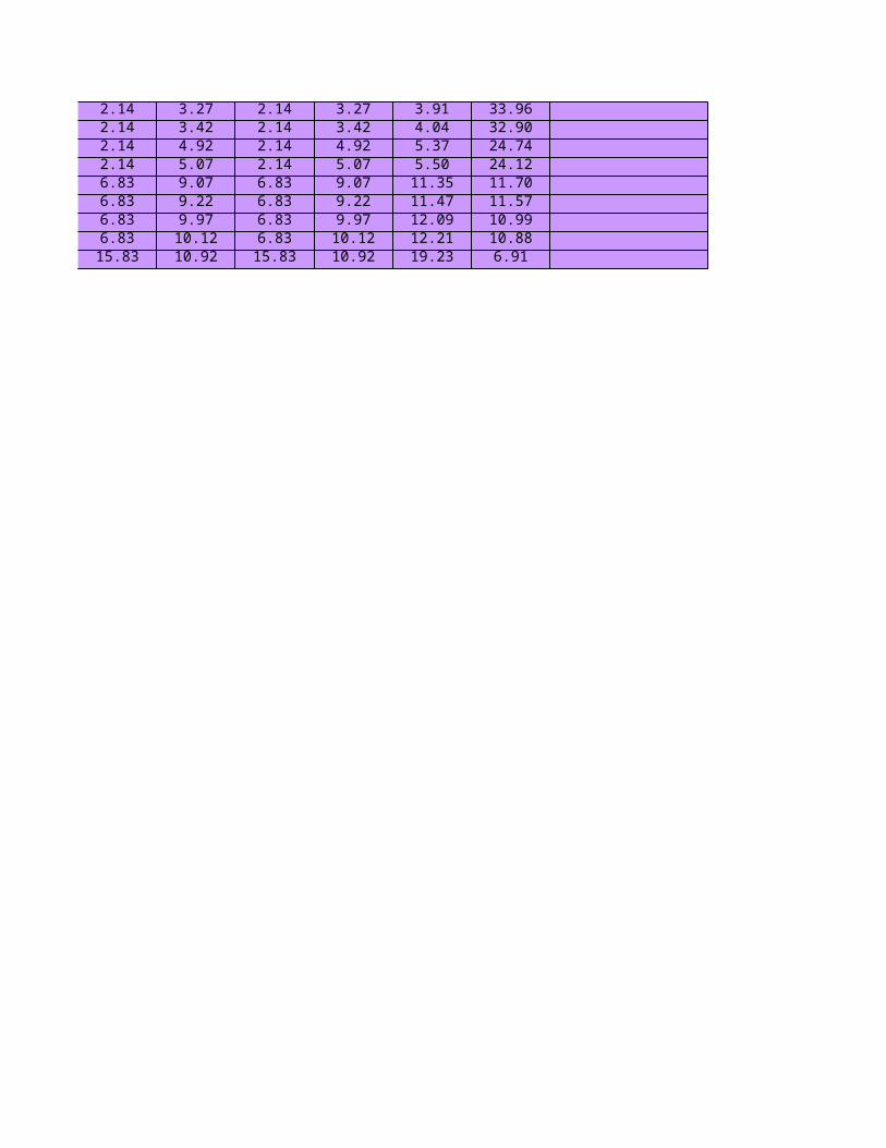
NO Item R(mΩ) X(mΩ) Z(mΩ) 0 0 Rt(mΩ)1 transformer 1.99 2.47 3.17 1.99 2.47 1.99
S (mm²)
2 cable (1) 0.15 0.8 0.81 2.14 3.27 2.143 circuit breaker (1) 0 0.15 0.15 2.14 3.42 2.144 busbar (1) 0 1.5 1.5 2.14 4.92 2.145 circuit breaker (2) 0 0.15 0.15 2.14 5.07 2.146 cable (2) 4.69 4 6.16 6.83 9.07 6.837 circuit breaker (3) 0 0.15 0.15 6.83 9.22 6.838 busbar (2) 0 0.75 0.75 6.83 9.97 6.839 circuit breaker (4) 0.00 0.15 0.15 6.83 10.12 6.83
10 cable (3) 9.00 0.80 9.04 15.83 10.92 15.83

(1) determination of the impedance of the HV network
COMMENT
Psc 500/250 MVAUo = 420 v , 400 v , for rated load 400v , 380 v
X,R,Z in milli ohm (mΩ) and Isc in KA
(2) determination of Isc at secondary terminals of a HV/LV distribution transformer
COMMENT
For roughly estimation Isc = In/Usc In= nominal current in amp. Usc = sc impedance voltage in %
(2) quick estimation
COMMENT
(3) determination of Isc for low voltage cables
COMMENT
L : length of cable in meter S : c.s.a of cable in mm²
N : no. of conductor /phase
(4) determination of Isc for circuit breaker
COMMENT
N : no of poleRd = 0 ( negligible )
Xd = 0.15 mΩ / pole
(5) determination of Isc for busbars
COMMENT
L : length of busbar in meterRb = 0 ( negligible )Xb = 0.15 mΩ / m
RESULTS COMMENT
Xt(mΩ) Zt(mΩ) Isc(KA)2.47 3.17 41.84
ρ :22.5 / 36 mΩxmm²/m for copper / alumimuim
3.27 3.91 33.963.42 4.04 32.904.92 5.37 24.745.07 5.50 24.129.07 11.35 11.709.22 11.47 11.579.97 12.09 10.99
10.12 12.21 10.8810.92 19.23 6.91
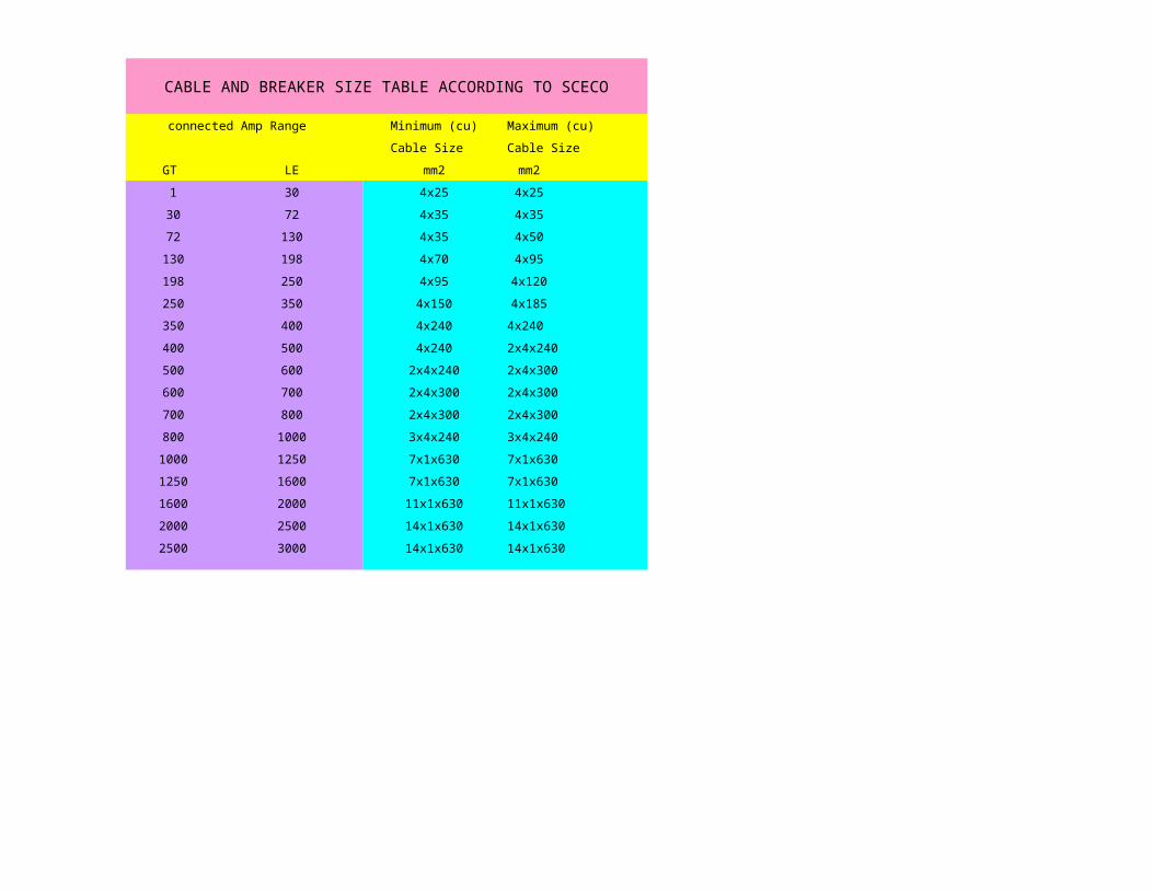
CABLE AND BREAKER SIZE TABLE ACCORDING TO SCECO
connected Amp Range Minimum (cu) Maximum (cu)
Cable Size Cable Size
GT LE mm2 mm2
1 30 4x25 4x25
30 72 4x35 4x35
72 130 4x35 4x50
130 198 4x70 4x95
198 250 4x95 4x120
250 350 4x150 4x185
350 400 4x240 4x240
400 500 4x240 2x4x240
500 600 2x4x240 2x4x300
600 700 2x4x300 2x4x300
700 800 2x4x300 2x4x300
800 1000 3x4x240 3x4x240
1000 1250 7x1x630 7x1x630
1250 1600 7x1x630 7x1x630
1600 2000 11x1x630 11x1x630
2000 2500 14x1x630 14x1x630
2500 3000 14x1x630 14x1x630

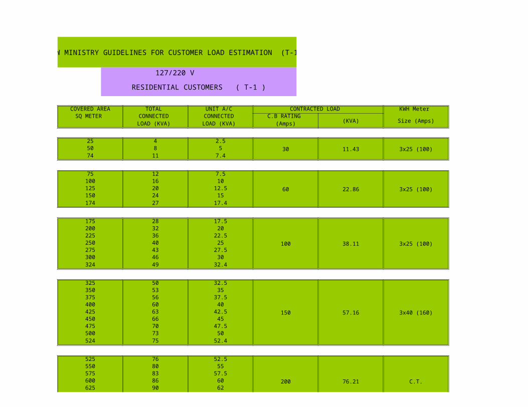
NEW MINISTRY GUIDELINES FOR CUSTOMER LOAD ESTIMATION (T-1)
127/220 V
RESIDENTIAL CUSTOMERS ( T-1 )
COVERED AREA TOTAL UNIT A/C CONTRACTED LOAD KWH Meter SQ METER CONNECTED CONNECTED C.B RATING
(KVA) Size (Amps)LOAD (KVA) LOAD (KVA) (Amps)
25 4 2.530 11.43 3x25 (100)50 8 5
74 11 7.4
75 12 7.5
60 22.86 3x25 (100)100 16 10125 20 12.5150 24 15174 27 17.4
175 28 17.5
100 38.11 3x25 (100)
200 32 20225 36 22.5250 40 25275 43 27.5300 46 30324 49 32.4
325 50 32.5
150 57.16 3x40 (160)
350 53 35375 56 37.5400 60 40425 63 42.5450 66 45475 70 47.5500 73 50524 75 52.4
525 76 52.5
200 76.21 C.T.
550 80 55575 83 57.5600 86 60625 90 62
650 93 65
200 76.21 C.T.
674 95 67.4
NEW MINISTRY GUIDELINES FOR CUSTOMER LOAD ESTIMATION
127/220 V
RESIDENTIAL CUSTOMERS ( T-1 )
675 96 67.5
300 114.32 C.T.
700 100 70725 103 72.5750 106 75775 110 77.5800 113 80825 116 82.5850 120 85875 123 87.5900 126 90925 130 92.5950 133 95
951 134 95.1
400 152.42 C.T.
975 136 97.51000 140 1001025 143 102.51050 146 1051075 150 107.51100 152 110
1101 153 110.1
500 190.53 C.T.
1125 156 112.51150 160 1151175 163 117.51200 166 1201300 180 1301400 193 1401500 206 1501600 220 1601658 228 165.8
1659 229 165.9
800 304.84 C.T.
1700 233 1701800 246 1801900 260 1902000 273 2002100 286 210

2200 300 220
800 304.84 C.T.
2236 305 223.6
NEW MINISTRY GUIDELINES FOR CUSTOMER LOAD ESTIMATION
127/220 V
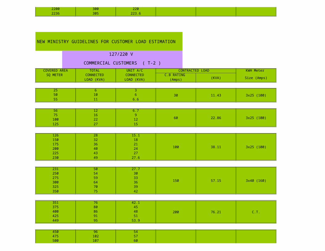
COMMERCIAL CUSTOMERS ( T-2 )
COVERED AREA TOTAL UNIT A/C CONTRACTED LOAD KWH Meter SQ METER CONNECTED CONNECTED C.B RATING
(KVA) Size (Amps)LOAD (KVA) LOAD (KVA) (Amps)
25 6 330 11.43 3x25 (100)50 10 6
55 11 6.6
56 12 6.7
60 22.86 3x25 (100)75 16 9
100 22 12125 27 15
126 28 15.1
100 38.11 3x25 (100)
150 32 18175 36 21200 40 24225 43 27230 49 27.6
231 50 27.7
150 57.15 3x40 (160)
250 54 30275 59 33300 64 36325 70 39350 75 42
351 76 42.1
200 76.21 C.T.375 80 45400 86 48425 91 51449 95 53.9
450 96 54
300 114.3 C.T.
475 102 57500 107 60
525 112 63300 114.3 C.T.
550 118 66575 123 69600 128 72624 133 74.9
NEW MINISTRY GUIDELINES FOR CUSTOMER LOAD ESTIMATION
127/220 V
COMMERCIAL CUSTOMERS ( T-2 )
COVERED AREA TOTAL UNIT A/C CONTRACTED LOAD KWH Meter SQ METER CONNECTED CONNECTED C.B RATING
(KVA) Size (Amps)LOAD (KVA) LOAD (KVA) (Amps)
625 134 75.5
400 152.4 C.T.650 139 78675 144 81700 150 84711 152 85.3
712 153 85.4
500190.5 C.T.
725 155 87750 160 90775 166 93800 171 96825 176 99850 182 102875 187 105900 192 108925 198 111950 203 114975 208 117
1000 214 1201025 219 1231050 224 1261069 228 128
1070 229 128.4
800304.8 C.T.
1075 230 1291100 235 1321125 240 1351150 246 1381175 250 1411200 256 1441300 278 1561400 299 1681429 305 171.5
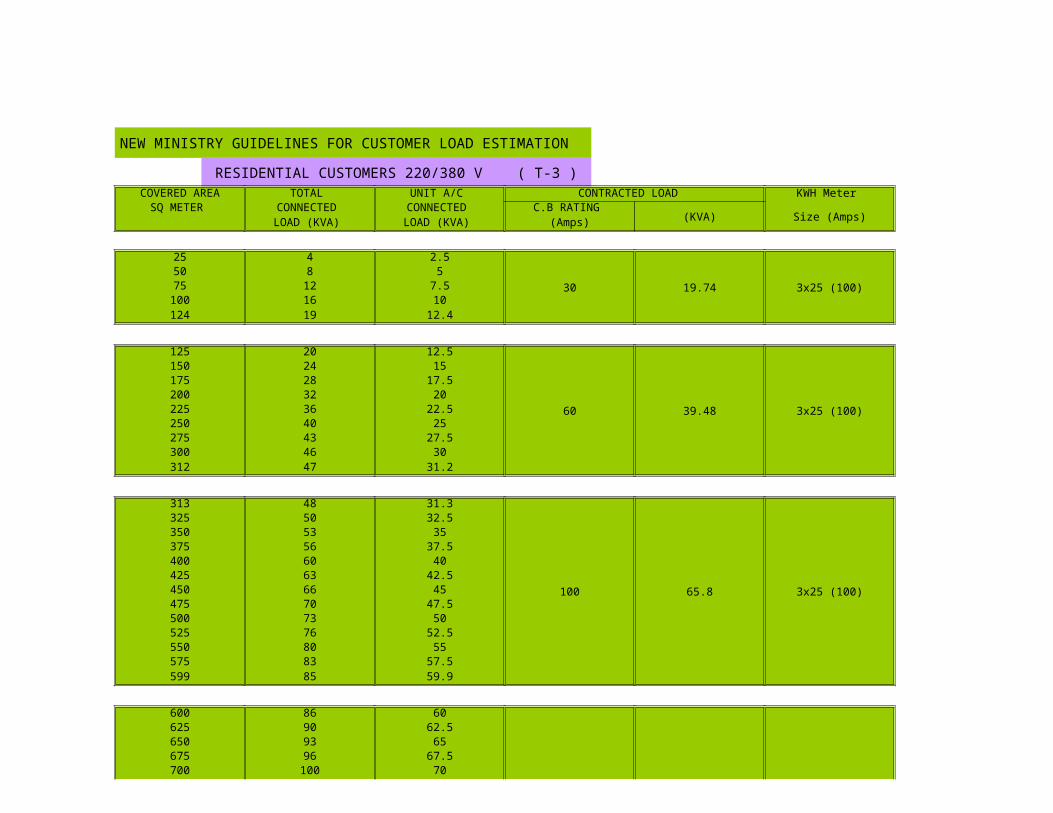
NEW MINISTRY GUIDELINES FOR CUSTOMER LOAD ESTIMATION
RESIDENTIAL CUSTOMERS 220/380 V ( T-3 )
COVERED AREA TOTAL UNIT A/C CONTRACTED LOAD KWH Meter SQ METER CONNECTED CONNECTED C.B RATING
(KVA) Size (Amps)LOAD (KVA) LOAD (KVA) (Amps)
25 4 2.5
30 19.74 3x25 (100)50 8 575 12 7.5
100 16 10124 19 12.4
125 20 12.5
60 39.48 3x25 (100)
150 24 15175 28 17.5200 32 20225 36 22.5250 40 25275 43 27.5300 46 30312 47 31.2
313 48 31.3
100 65.8 3x25 (100)
325 50 32.5350 53 35375 56 37.5400 60 40425 63 42.5450 66 45475 70 47.5500 73 50525 76 52.5550 80 55575 83 57.5599 85 59.9
600 86 60
150 98.7 3x40 (160)
625 90 62.5650 93 65675 96 67.5700 100 70
725 103 72.5
150 98.7 3x40 (160)750 106 75775 110 77.5800 113 80825 116 82.5850 120 85875 123 87.5900 126 90930 130 93
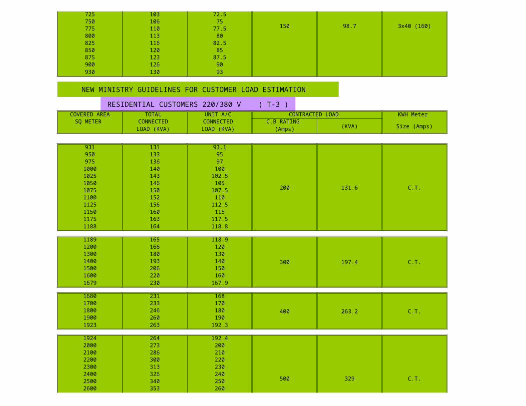
NEW MINISTRY GUIDELINES FOR CUSTOMER LOAD ESTIMATION
RESIDENTIAL CUSTOMERS 220/380 V ( T-3 )
COVERED AREA TOTAL UNIT A/C CONTRACTED LOAD KWH Meter SQ METER CONNECTED CONNECTED C.B RATING
(KVA) Size (Amps)LOAD (KVA) LOAD (KVA) (Amps)
931 131 93.1
200 131.6 C.T.
950 133 95975 136 97
1000 140 1001025 143 102.51050 146 1051075 150 107.51100 152 1101125 156 112.51150 160 1151175 163 117.51188 164 118.8
1189 165 118.9
300 197.4 C.T.
1200 166 1201300 180 1301400 193 1401500 206 1501600 220 1601679 230 167.9
1680 231 168
400 263.2 C.T.1700 233 1701800 246 1801900 260 1901923 263 192.3
1924 264 192.4
500 329 C.T.
2000 273 2002100 286 2102200 300 2202300 313 2302400 326 2402500 340 2502600 353 260
2700 366 270
500 329 C.T.
2800 380 2802900 393 2902916 395 291.6
2917 396 291.7800 526.4 C.T.3000 406 300
3890 526 389
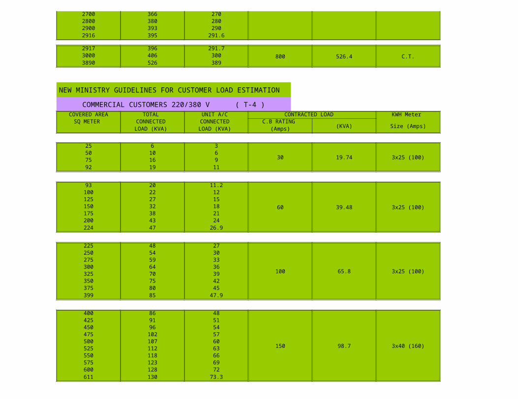
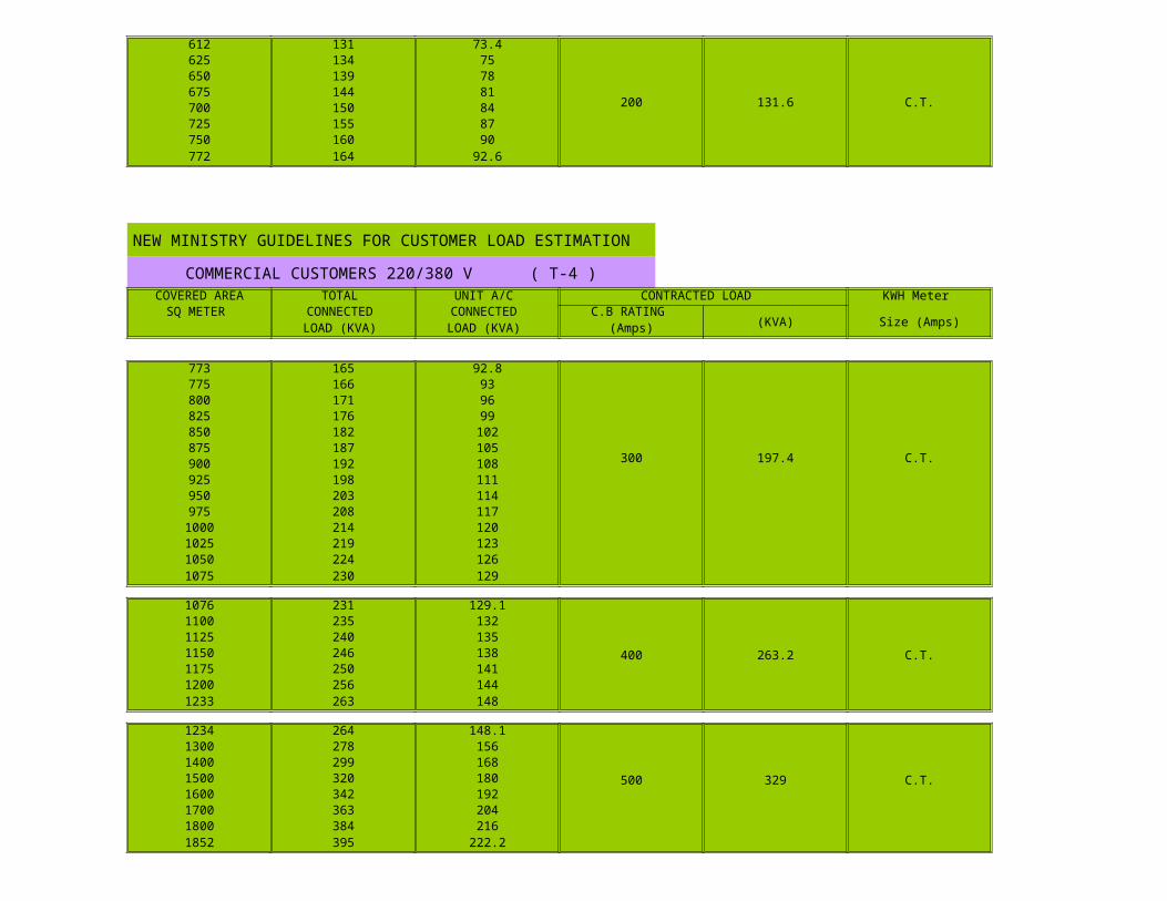
NEW MINISTRY GUIDELINES FOR CUSTOMER LOAD ESTIMATION
COMMERCIAL CUSTOMERS 220/380 V ( T-4 )
COVERED AREA TOTAL UNIT A/C CONTRACTED LOAD KWH Meter SQ METER CONNECTED CONNECTED C.B RATING
(KVA) Size (Amps)LOAD (KVA) LOAD (KVA) (Amps)
25 6 3
30 19.74 3x25 (100)50 10 675 16 992 19 11
93 20 11.2
60 39.48 3x25 (100)
100 22 12125 27 15150 32 18175 38 21200 43 24224 47 26.9
225 48 27
100 65.8 3x25 (100)
250 54 30275 59 33300 64 36325 70 39350 75 42375 80 45399 85 47.9
400 86 48
150 98.7 3x40 (160)
425 91 51450 96 54475 102 57500 107 60525 112 63550 118 66575 123 69600 128 72611 130 73.3
612 131 73.4
200 131.6 C.T.
625 134 75650 139 78675 144 81700 150 84725 155 87750 160 90772 164 92.6
NEW MINISTRY GUIDELINES FOR CUSTOMER LOAD ESTIMATION
COMMERCIAL CUSTOMERS 220/380 V ( T-4 )
COVERED AREA TOTAL UNIT A/C CONTRACTED LOAD KWH Meter SQ METER CONNECTED CONNECTED C.B RATING
(KVA) Size (Amps)LOAD (KVA) LOAD (KVA) (Amps)
773 165 92.8
300 197.4 C.T.
775 166 93800 171 96825 176 99850 182 102875 187 105900 192 108925 198 111950 203 114975 208 117
1000 214 1201025 219 1231050 224 1261075 230 129
1076 231 129.1
400 263.2 C.T.
1100 235 1321125 240 1351150 246 1381175 250 1411200 256 1441233 263 148
1234 264 148.1
500 329 C.T.
1300 278 1561400 299 1681500 320 1801600 342 1921700 363 2041800 384 2161852 395 222.2
1853 396 222.4
800 526.4 C.T.
1900 405 2282000 427 2402100 448 2522200 469 2642300 491 2762400 512 2882465 526 295.8
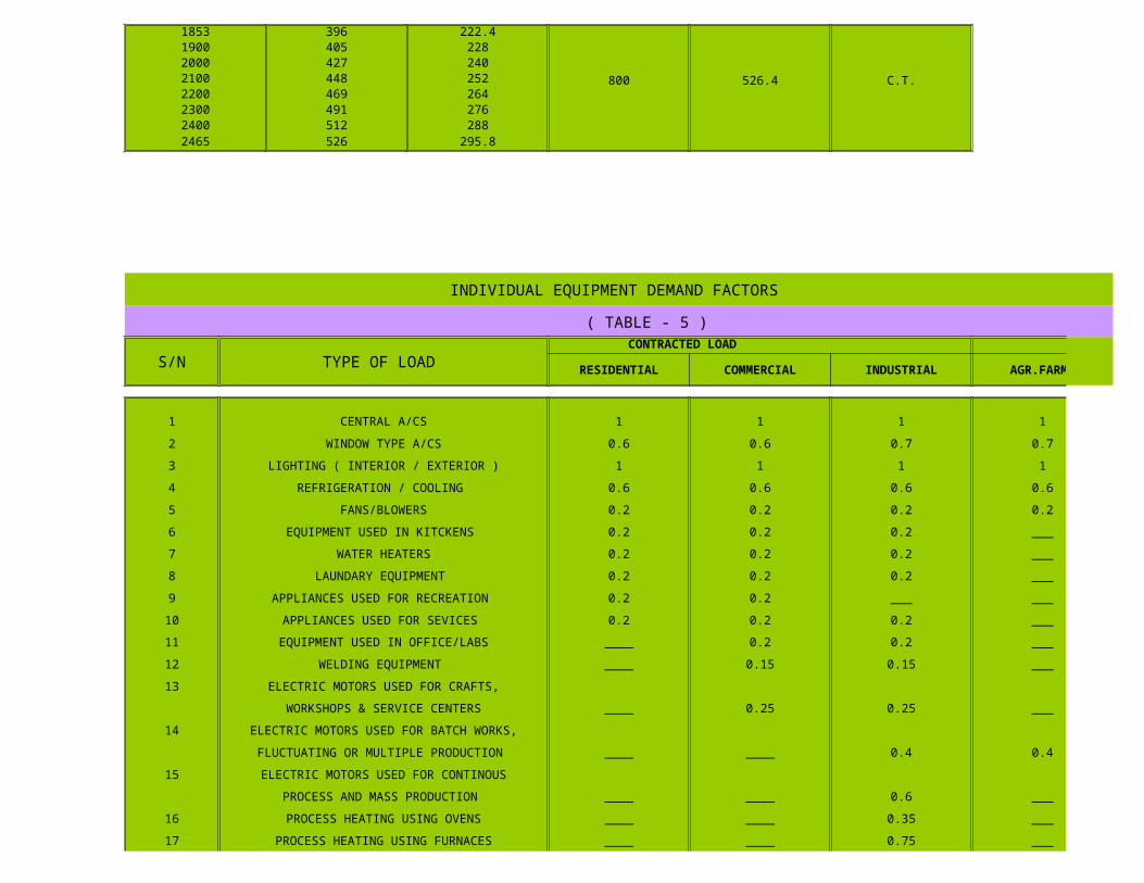
INDIVIDUAL EQUIPMENT DEMAND FACTORS
( TABLE - 5 )
S/N TYPE OF LOAD CONTRACTED LOAD
RESIDENTIAL COMMERCIAL INDUSTRIAL AGR.FARMS
1 CENTRAL A/CS 1 1 1 1
2 WINDOW TYPE A/CS 0.6 0.6 0.7 0.7
3 LIGHTING ( INTERIOR / EXTERIOR ) 1 1 1 1
4 REFRIGERATION / COOLING 0.6 0.6 0.6 0.6
5 FANS/BLOWERS 0.2 0.2 0.2 0.2
6 EQUIPMENT USED IN KITCKENS 0.2 0.2 0.2 ___
7 WATER HEATERS 0.2 0.2 0.2 ___
8 LAUNDARY EQUIPMENT 0.2 0.2 0.2 ___
9 APPLIANCES USED FOR RECREATION 0.2 0.2 ___ ___
10 APPLIANCES USED FOR SEVICES 0.2 0.2 0.2 ___
11 EQUIPMENT USED IN OFFICE/LABS ____ 0.2 0.2 ___
12 WELDING EQUIPMENT ____ 0.15 0.15 ___
13 ELECTRIC MOTORS USED FOR CRAFTS,
WORKSHOPS & SERVICE CENTERS ____ 0.25 0.25 ___
14 ELECTRIC MOTORS USED FOR BATCH WORKS,
FLUCTUATING OR MULTIPLE PRODUCTION ____ ____ 0.4 0.4
15 ELECTRIC MOTORS USED FOR CONTINOUS
PROCESS AND MASS PRODUCTION ____ ____ 0.6 ___
16 PROCESS HEATING USING OVENS ____ ____ 0.35 ___
17 PROCESS HEATING USING FURNACES ____ ____ 0.75 ___
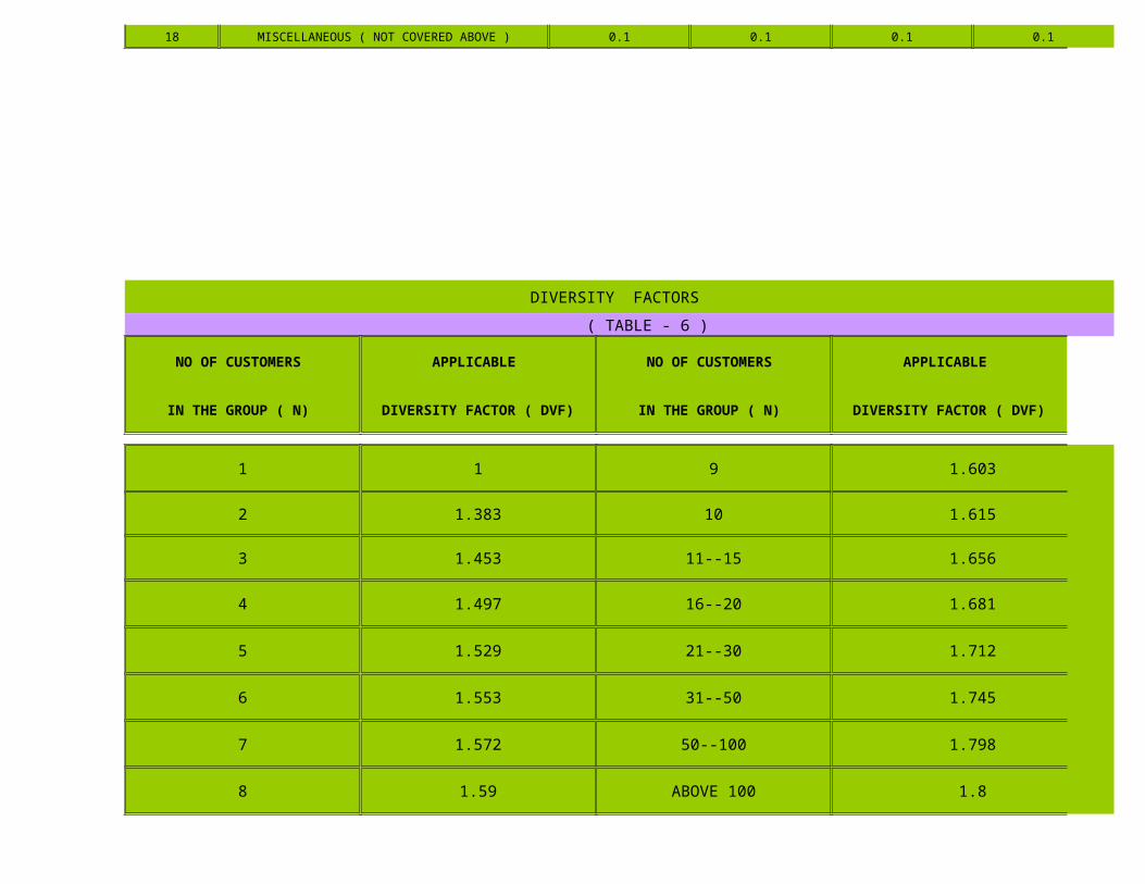
18 MISCELLANEOUS ( NOT COVERED ABOVE ) 0.1 0.1 0.1 0.1
DIVERSITY FACTORS
( TABLE - 6 )
NO OF CUSTOMERS APPLICABLE NO OF CUSTOMERS APPLICABLE
IN THE GROUP ( N) DIVERSITY FACTOR ( DVF) IN THE GROUP ( N) DIVERSITY FACTOR ( DVF)
1 1 9 1.603
2 1.383 10 1.615
3 1.453 11--15 1.656
4 1.497 16--20 1.681
5 1.529 21--30 1.712
6 1.553 31--50 1.745
7 1.572 50--100 1.798
8 1.59 ABOVE 100 1.8

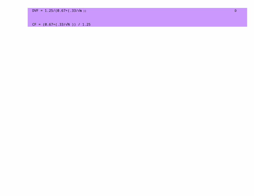
CF = (0.67+(.33/√N )) / 1.25 CF = COVERAGE FACTOR
DVF = 1.25/(0.67+(.33/√N )) DVF = DIVERSITY FACTOR

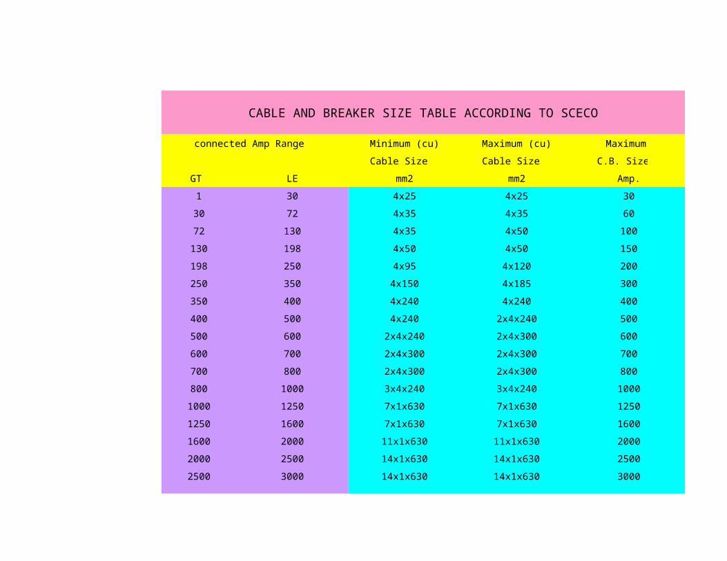
CABLE AND BREAKER SIZE TABLE ACCORDING TO SCECO
connected Amp Range Minimum (cu) Maximum (cu) Maximum
Cable Size Cable Size C.B. Size
GT LE mm2 mm2 Amp.
1 30 4x25 4x25 30
30 72 4x35 4x35 60
72 130 4x35 4x50 100
130 198 4x50 4x50 150
198 250 4x95 4x120 200
250 350 4x150 4x185 300
350 400 4x240 4x240 400
400 500 4x240 2x4x240 500
500 600 2x4x240 2x4x300 600
600 700 2x4x300 2x4x300 700
700 800 2x4x300 2x4x300 800
800 1000 3x4x240 3x4x240 1000
1000 1250 7x1x630 7x1x630 1250
1250 1600 7x1x630 7x1x630 1600
1600 2000 11x1x630 11x1x630 2000
2000 2500 14x1x630 14x1x630 2500
2500 3000 14x1x630 14x1x630 3000

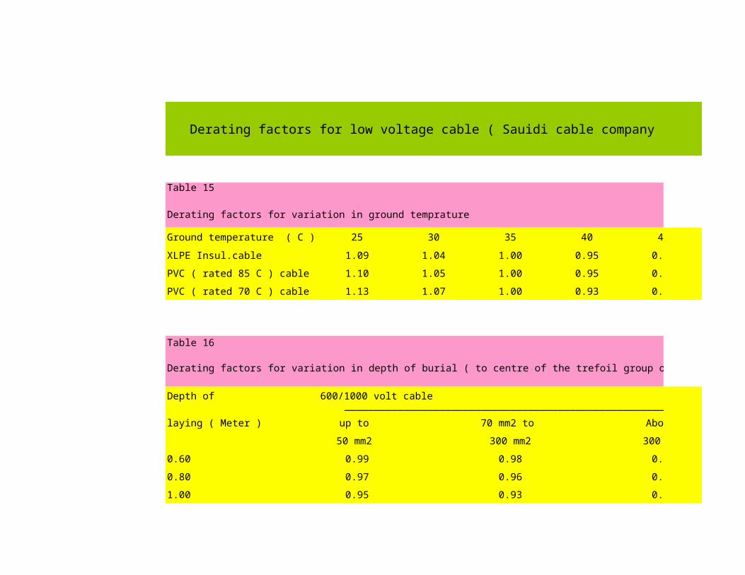
Derating factors for low voltage cable ( Sauidi cable company )
Table 15
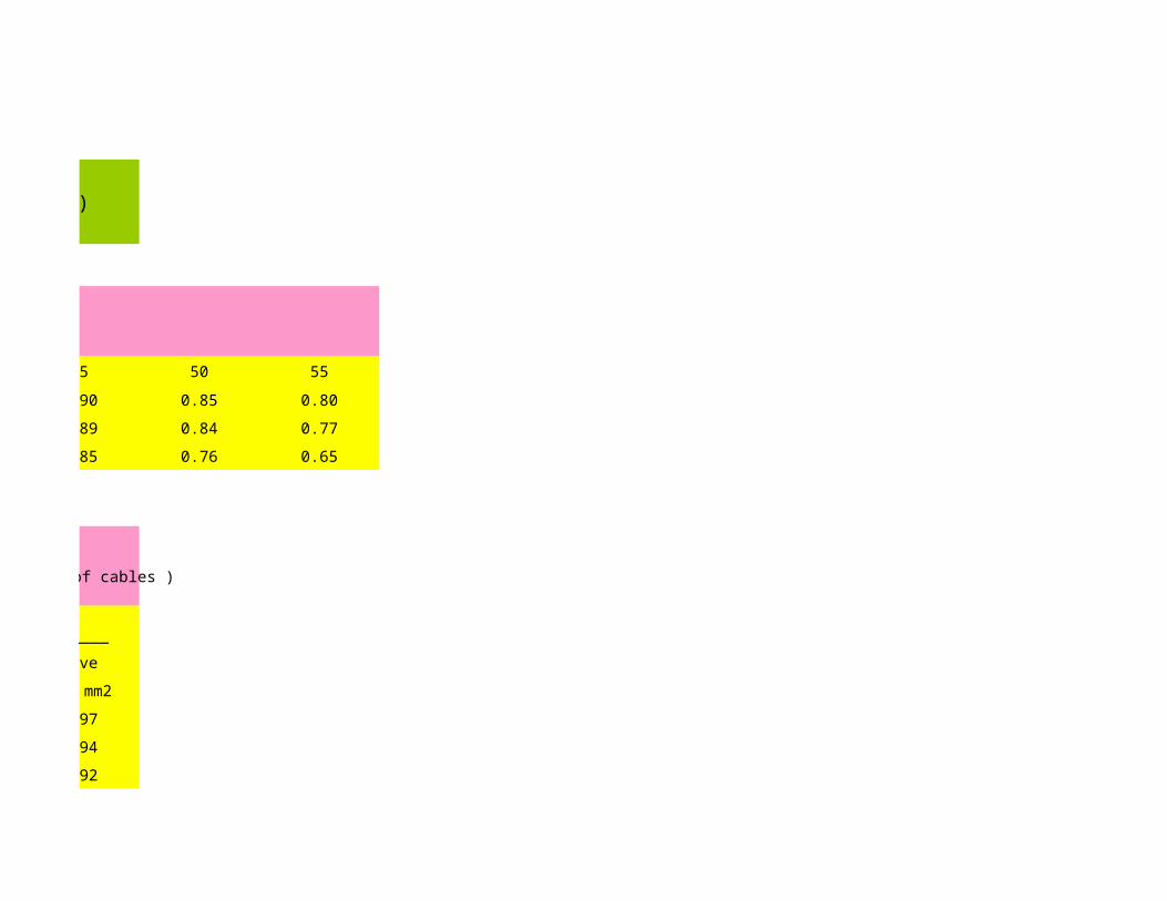
Derating factors for variation in ground temprature
Ground temperature ( C ) 25 30 35 40 45 50
XLPE Insul.cable 1.09 1.04 1.00 0.95 0.90 0.85
PVC ( rated 85 C ) cable 1.10 1.05 1.00 0.95 0.89 0.84
PVC ( rated 70 C ) cable 1.13 1.07 1.00 0.93 0.85 0.76
Table 16
Derating factors for variation in depth of burial ( to centre of the trefoil group of cables )
Depth of 600/1000 volt cable _________________________________________________________
laying ( Meter ) up to 70 mm2 to Above
50 mm2 300 mm2 300 mm2
0.60 0.99 0.98 0.97
0.80 0.97 0.96 0.94
1.00 0.95 0.93 0.92
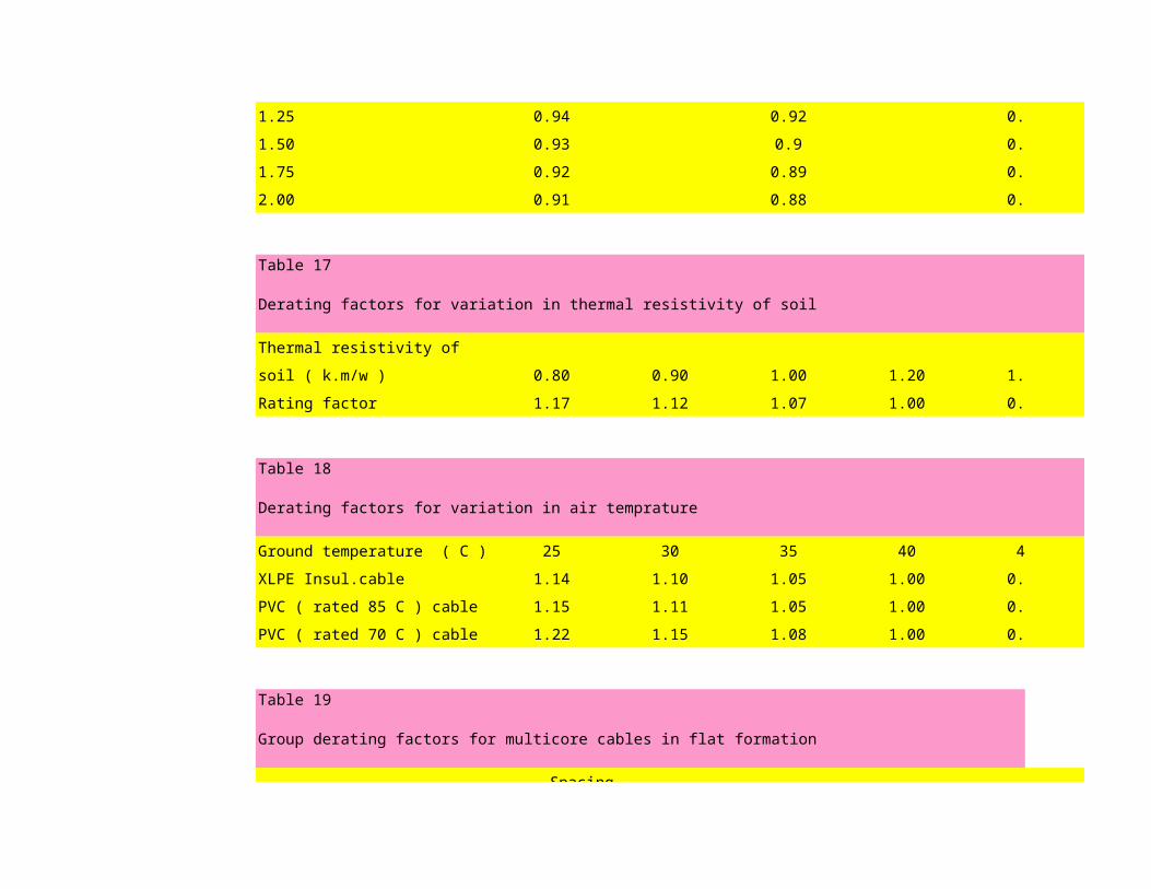
1.25 0.94 0.92 0.89
1.50 0.93 0.9 0.87
1.75 0.92 0.89 0.86
2.00 0.91 0.88 0.85
Table 17
Derating factors for variation in thermal resistivity of soil
Thermal resistivity of
soil ( k.m/w ) 0.80 0.90 1.00 1.20 1.50 2.00
Rating factor 1.17 1.12 1.07 1.00 0.89 0.84
Table 18
Derating factors for variation in air temprature
Ground temperature ( C ) 25 30 35 40 45 50
XLPE Insul.cable 1.14 1.10 1.05 1.00 0.95 0.89
PVC ( rated 85 C ) cable 1.15 1.11 1.05 1.00 0.94 0.88
PVC ( rated 70 C ) cable 1.22 1.15 1.08 1.00 0.91 0.82
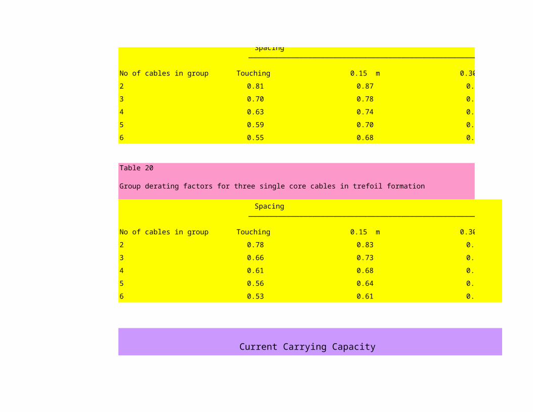
Table 19
Group derating factors for multicore cables in flat formation
Spacing
Spacing _______________________________________________________
No of cables in group Touching 0.15 m 0.30 m
2 0.81 0.87 0.91
3 0.70 0.78 0.84
4 0.63 0.74 0.81
5 0.59 0.70 0.78
6 0.55 0.68 0.77
Table 20
Group derating factors for three single core cables in trefoil formation
Spacing _______________________________________________________
No of cables in group Touching 0.15 m 0.30 m
2 0.78 0.83 0.88
3 0.66 0.73 0.79
4 0.61 0.68 0.73
5 0.56 0.64 0.73
6 0.53 0.61 0.71
Current Carrying Capacity
Current Carrying Capacity
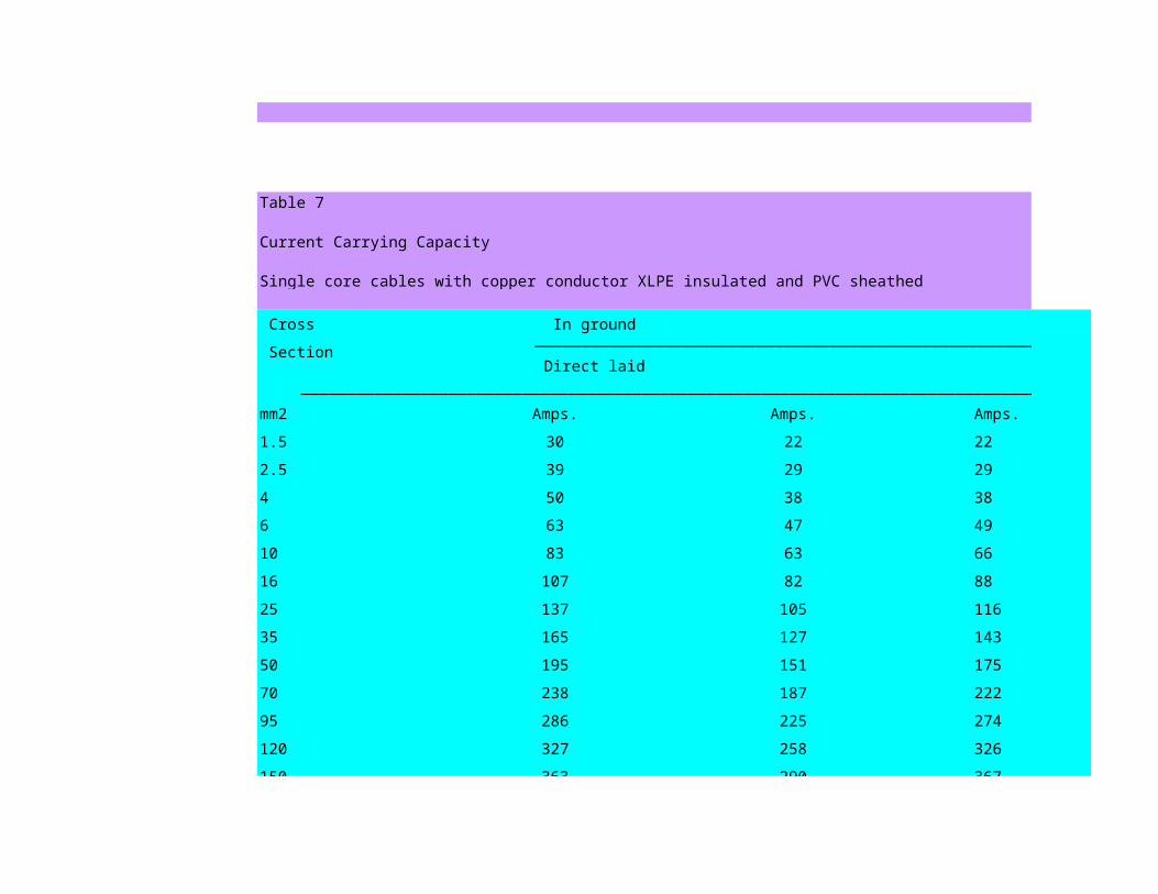
Table 7
Current Carrying Capacity
Single core cables with copper conductor XLPE insulated and PVC sheathed
Cross In ground In air
Section _____________________________________________________________________
Direct laid In duct Free In Pipe
______________________________________________________________________________________________
mm2 Amps. Amps. Amps. Amps.
1.5 30 22 22 19
2.5 39 29 29 24
4 50 38 38 32
6 63 47 49 40
10 83 63 66 54
16 107 82 88 70
25 137 105 116 92
35 165 127 143 112
50 195 151 175 134
70 238 187 222 168
95 286 225 274 205
120 327 258 326 237
150 363 290 367 269
150 363 290 367 269
185 410 330 425 308
240 474 382 505 361
300 532 431 583 411
400 600 489 676 469
500 673 550 779 533
630 752 615 900 603
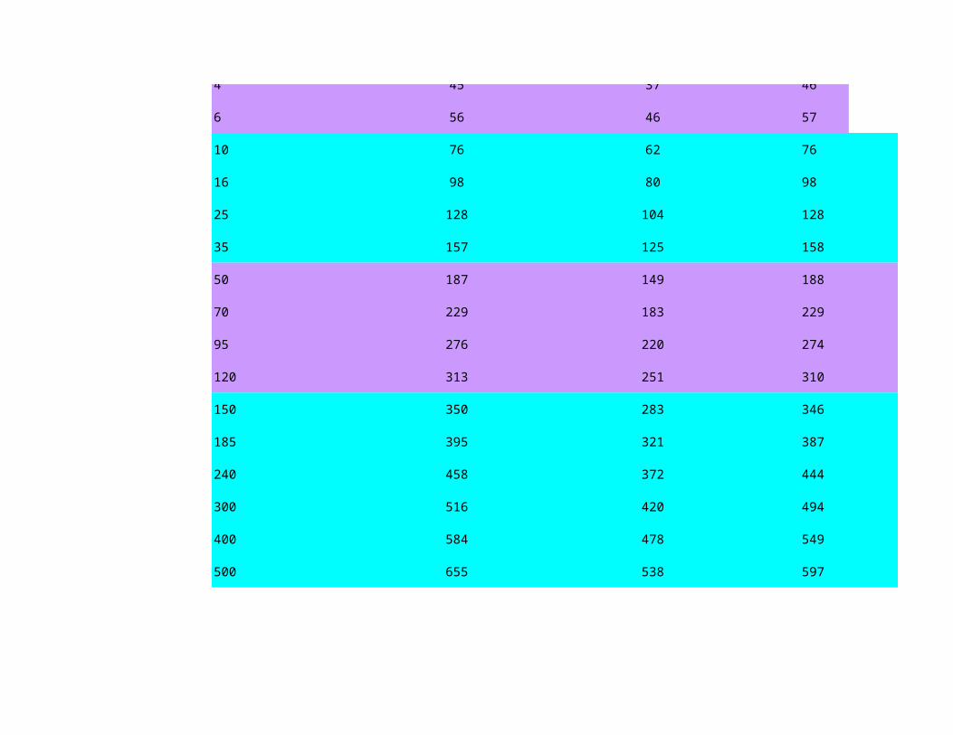
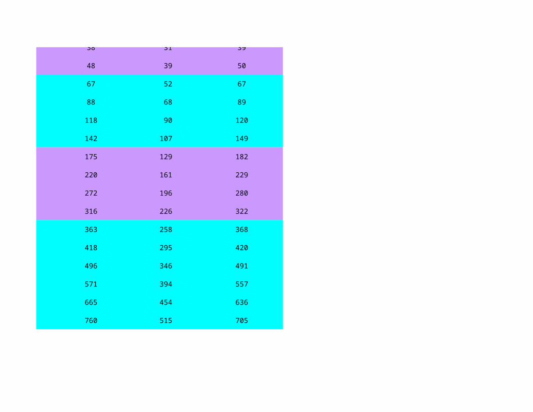
Table 7
Current Carrying Capacity
Three and four core cables with copper conductor XLPE insulated and PVC sheathed
Cross In ground
Section _____________________________________________________________________________________________________________
Unarmoured Armoured
_____________________________________________________________________________________________________________ Direct laid In duct Direct laid Free
mm2 Amps. Amps. Amps. Amps.
1.5 27 22 - 22
2.5 35 29 - 29
4 45 37 46 38
In air
Unarmoured
4 45 37 46 38
6 56 46 57 48
10 76 62 76 67
16 98 80 98 88
25 128 104 128 118
35 157 125 158 142
50 187 149 188 175
70 229 183 229 220
95 276 220 274 272
120 313 251 310 316
150 350 283 346 363
185 395 321 387 418
240 458 372 444 496
300 516 420 494 571
400 584 478 549 665
500 655 538 597 760

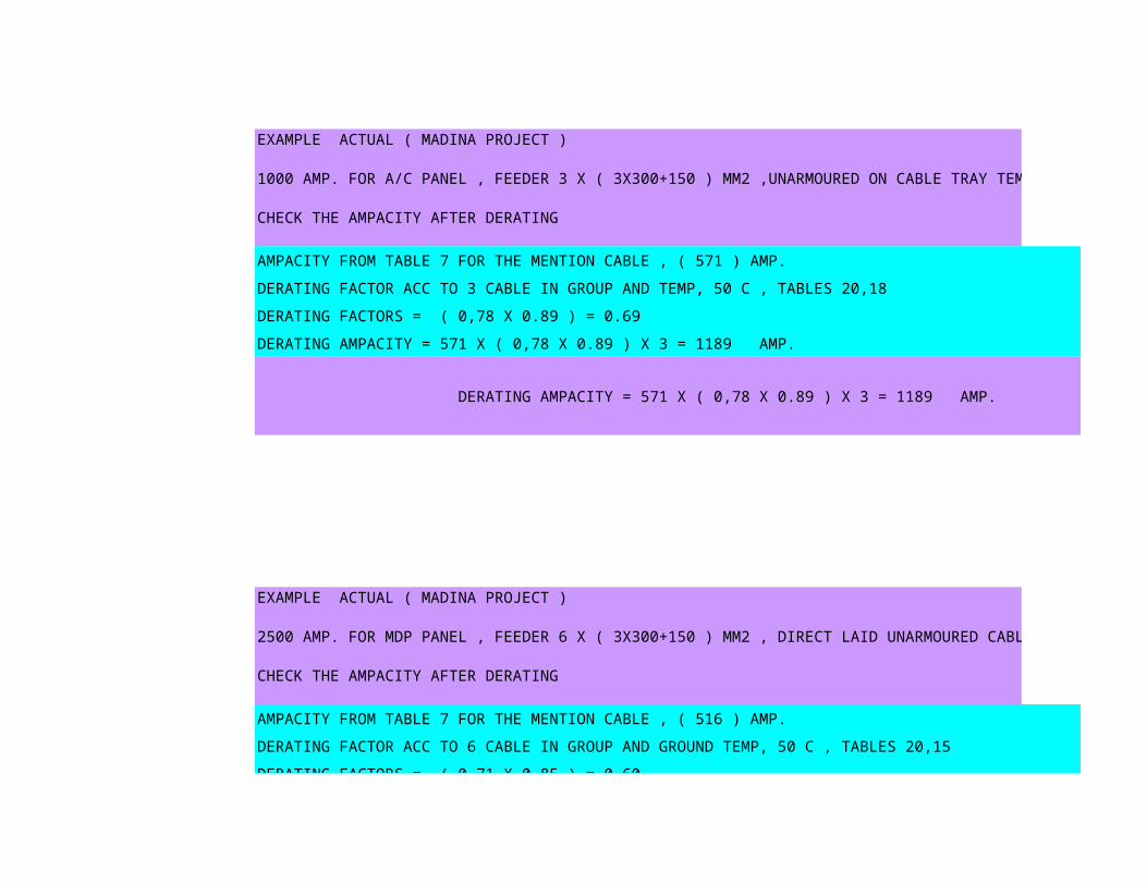
EXAMPLE ACTUAL ( MADINA PROJECT )
1000 AMP. FOR A/C PANEL , FEEDER 3 X ( 3X300+150 ) MM2 ,UNARMOURED ON CABLE TRAY TEMP 50 C
CHECK THE AMPACITY AFTER DERATING
AMPACITY FROM TABLE 7 FOR THE MENTION CABLE , ( 571 ) AMP.
DERATING FACTOR ACC TO 3 CABLE IN GROUP AND TEMP, 50 C , TABLES 20,18
DERATING FACTORS = ( 0,78 X 0.89 ) = 0.69
DERATING AMPACITY = 571 X ( 0,78 X 0.89 ) X 3 = 1189 AMP.
DERATING AMPACITY = 571 X ( 0,78 X 0.89 ) X 3 = 1189 AMP.
EXAMPLE ACTUAL ( MADINA PROJECT )
2500 AMP. FOR MDP PANEL , FEEDER 6 X ( 3X300+150 ) MM2 , DIRECT LAID UNARMOURED CABLE
CHECK THE AMPACITY AFTER DERATING
AMPACITY FROM TABLE 7 FOR THE MENTION CABLE , ( 516 ) AMP.
DERATING FACTOR ACC TO 6 CABLE IN GROUP AND GROUND TEMP, 50 C , TABLES 20,15
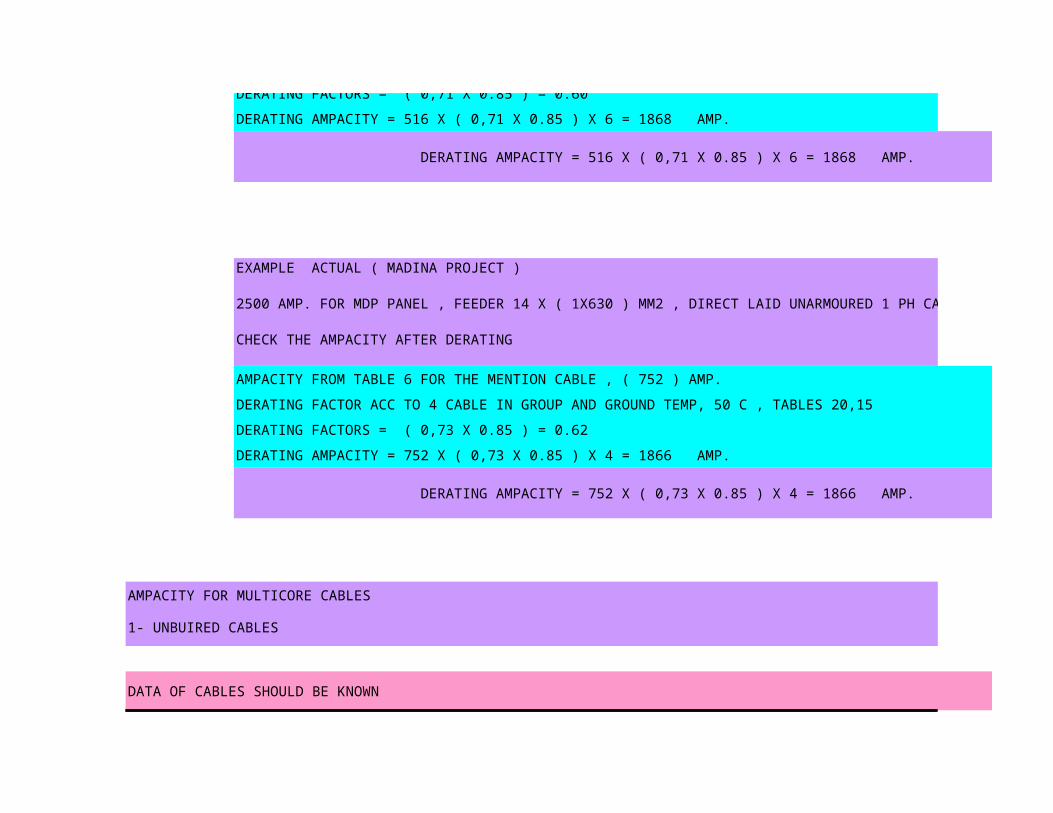
DERATING FACTORS = ( 0,71 X 0.85 ) = 0.60
DERATING FACTORS = ( 0,71 X 0.85 ) = 0.60
DERATING AMPACITY = 516 X ( 0,71 X 0.85 ) X 6 = 1868 AMP.
DERATING AMPACITY = 516 X ( 0,71 X 0.85 ) X 6 = 1868 AMP.
EXAMPLE ACTUAL ( MADINA PROJECT )
2500 AMP. FOR MDP PANEL , FEEDER 14 X ( 1X630 ) MM2 , DIRECT LAID UNARMOURED 1 PH CABLE
CHECK THE AMPACITY AFTER DERATING
AMPACITY FROM TABLE 6 FOR THE MENTION CABLE , ( 752 ) AMP.
DERATING FACTOR ACC TO 4 CABLE IN GROUP AND GROUND TEMP, 50 C , TABLES 20,15
DERATING FACTORS = ( 0,73 X 0.85 ) = 0.62
DERATING AMPACITY = 752 X ( 0,73 X 0.85 ) X 4 = 1866 AMP.
DERATING AMPACITY = 752 X ( 0,73 X 0.85 ) X 4 = 1866 AMP.
AMPACITY FOR MULTICORE CABLES
1- UNBUIRED CABLES
DATA OF CABLES SHOULD BE KNOWN
rated CABLE SIZELOAD KW
AMPACITY INSTALLATION FACTOR TEMP. FACTOR GROUP FACTOR
voltage mm2 (A) K1 K2 K3
380 16 25 88 1 1 0.7
RESULT
RATED CURRENT Ib (A) CIRCUIT BREAKER In (A)
MAX.CIRCUIT CURRENT Iz (A)
COMMENTS
DERATED AMPACITY
47.48 62 62
FOR CIRCUIT BRAKER
Ib ≤ In ≤ Iz
Derating factors for variation in ground temprature
50 55
0.85 0.80
0.84 0.77
0.76 0.65

2.00 2.00
0.84 0.77
50 55
0.89 0.84
0.88 0.82
0.82 0.71

In air _____________________________________________________________________
In Pipe
______________________________________________________________________________________________
Amps.
19
24
32
40
54
70
92
112
134
168
205
237
269
269269
308
361
411
469
533
603
_____________________________________________________________________________________________________________
Armoured
_____________________________________________________________________________________________________________ Free In Pipe Free
Amps. Amps. Amps.
22 18 -
29 24 -
38 31 39
In air
Unarmoured

3838 31 39
48 39 50
67 52 67
88 68 89
118 90 120
142 107 149
175 129 182
220 161 229
272 196 280
316 226 322
363 258 368
418 295 420
496 346 491
571 394 557
665 454 636
760 515 705

1000 AMP. FOR A/C PANEL , FEEDER 3 X ( 3X300+150 ) MM2 ,UNARMOURED ON CABLE TRAY TEMP 50 C
AMPACITY FROM TABLE 7 FOR THE MENTION CABLE , ( 571 ) AMP.
DERATING FACTOR ACC TO 3 CABLE IN GROUP AND TEMP, 50 C , TABLES 20,18
DERATING FACTORS = ( 0,78 X 0.89 ) = 0.69
DERATING AMPACITY = 571 X ( 0,78 X 0.89 ) X 3 = 1189 AMP.
DERATING AMPACITY = 571 X ( 0,78 X 0.89 ) X 3 = 1189 AMP.
AMPACITY FROM TABLE 7 FOR THE MENTION CABLE , ( 516 ) AMP.
DERATING FACTOR ACC TO 6 CABLE IN GROUP AND GROUND TEMP, 50 C , TABLES 20,15
DERATING FACTORS = ( 0,71 X 0.85 ) = 0.60

DERATING FACTORS = ( 0,71 X 0.85 ) = 0.60
DERATING AMPACITY = 516 X ( 0,71 X 0.85 ) X 6 = 1868 AMP.
DERATING AMPACITY = 516 X ( 0,71 X 0.85 ) X 6 = 1868 AMP.
AMPACITY FROM TABLE 6 FOR THE MENTION CABLE , ( 752 ) AMP.
DERATING FACTOR ACC TO 4 CABLE IN GROUP AND GROUND TEMP, 50 C , TABLES 20,15
DERATING FACTORS = ( 0,73 X 0.85 ) = 0.62
DERATING AMPACITY = 752 X ( 0,73 X 0.85 ) X 4 = 1866 AMP.
DERATING AMPACITY = 752 X ( 0,73 X 0.85 ) X 4 = 1866 AMP.
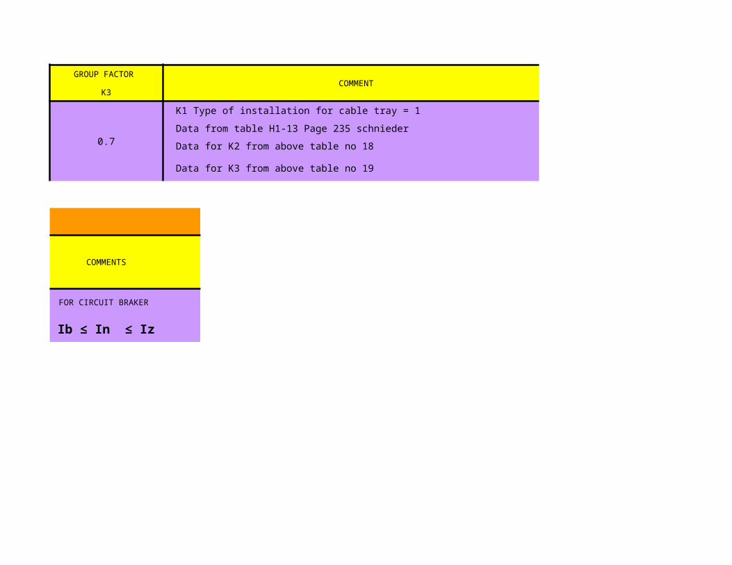
DATA OF CABLES SHOULD BE KNOWN

GROUP FACTOR COMMENT
K3
0.7
K1 Type of installation for cable tray = 1
Data from table H1-13 Page 235 schnieder
Data for K2 from above table no 18
Data for K3 from above table no 19
RESULT
COMMENTS
FOR CIRCUIT BRAKER
Ib ≤ In ≤ Iz
Approximate voltage drop at 60 hz for single core stranded plain copper / aluminium conductors
XLPE insulation , PVC sheath 600/1000 volts
Nominal area of Copper conductor Aluminium conductor
conductor mv / amp / m mv / amp / m
1.5 22.9 -
2.5 14.1 -
4 8.8 -
6 5.9 -
10 3.6 -
16 2.3 3.7
25 1.5 2.4
35 1.1 1.8
50 0.84 1.3
70 0.61 0.95
95 0.47 0.71
120 0.39 0.58
150 0.34 0.5
185 0.29 0.42
240 0.25 0.34
300 0.22 0.29
400 0.19 0.25
500 0.17 0.22

630 0.16 0.19
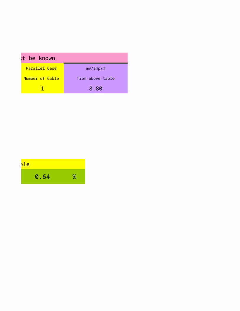
data for single phase cable must be known
length of cable rated current rated voltage Parallel Case
in meter in amp in volt Number of Cable
14 11.4 220 1
% voltage drop
in percentage
0.64
single phase cable
the percentage voltage drop = 0.64

Approximate voltage drop at 60 hz for single core stranded plain copper / aluminium conductors
XLPE insulation , PVC sheath 600/1000 volts
data for single phase cable must be known
Parallel Case mv/amp/m
Number of Cable from above table
1 8.80
single phase cable
0.64 %

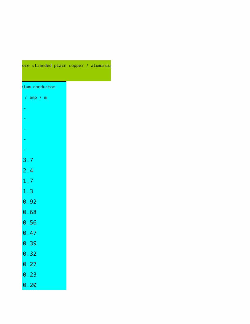
Approximate voltage drop at 60 hz for three and four core stranded plain copper / aluminium conductors
XLPE insulation , PVC sheath 600/1000 volts
Nominal area of Copper conductor Aluminium conductor
conductor mv / amp / m mv / amp / m
1.5 22.8 -
2.5 14 -
4 8.7 -
6 5.9 -
10 3.5 -
16 2.2 3.7
25 1.5 2.4
35 1.1 1.7
50 0.81 1.3
70 0.58 0.92
95 0.44 0.68
120 0.37 0.56
150 0.31 0.47
185 0.27 0.39
240 0.23 0.32
300 0.20 0.27
400 0.18 0.23
500 0.15 0.20

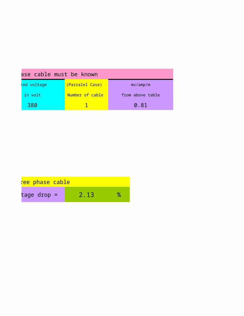
data for three phase cable must be known
length of cable rated current rated voltage
in meter in amp in volt
100 100 380
% voltage drop
in percentage
2.13
three phase cable
the percentage voltage drop =

Approximate voltage drop at 60 hz for three and four core stranded plain copper / aluminium conductors
XLPE insulation , PVC sheath 600/1000 volts
Aluminium conductor
mv / amp / m
-
-
-
-
-
3.7
2.4
1.7
1.3
0.92
0.68
0.56
0.47
0.39
0.32
0.27
0.23
0.20
data for three phase cable must be known
rated voltage (Parralel Case) mv/amp/m
in volt Number of cable from above table
380 1 0.81
three phase cable
the percentage voltage drop = 2.13 %

Single Core THHN Wires ( 600 V )
Copper Conductor PVC Insulated NAYLON Jacketed THHN / THWN Wires UL 83,1581
AWG
Equiv. Overall
CommentDiameter
mm² mm
18 2.3
16 2.5
14 2.9
12 3.4
10 4.3
8 8.37 5.6
Single Core
Unarmoured Cable - Copper Conductors XLPE insulation , PVC sheath 600/1000 volts
Nominal Overall
CommentArea Diameter
mm
1x1.5 6
1x2.5 7
1x4 7
1x6 8
1x10 9
1x16 10
1x25 11
1x35 13
1x50 14
1x70 16
1x95 18
1x120 20
1x150 22
1x185 24
1x240 27
1x300 30
1x400 34
1x500 37
1x630 42
Two Core
Unarmoured Cable - Copper Conductors XLPE insulation , PVC sheath 600/1000 volts
0.82 ~ 1
1.31 ~ 1.5
2.08 ~ 2
3.31 ~ 4
5.26 ~ 6
mm²

Unarmoured Cable - Copper Conductors XLPE insulation , PVC sheath 600/1000 volts
Nominal Overall
CommentArea Diameter
mm
2x1.5 13
2x2.5 13
2x4 14
2x6 16
2x10 17
2x16 19
2x25 23
2x35 25
Three Core
Unarmoured Cable - Copper Conductors XLPE insulation , PVC sheath 600/1000 volts
Nominal Overall
CommentArea Diameter
mm
3x1.5 11
3x2.5 12.5
3x4 13.5
3x6 15.5
3x10 19
3x16 21.5
four Core
Unarmoured Cable - Copper Conductors XLPE insulation , PVC sheath 600/1000 volts
Nominal Overall
CommentArea Diameter
mm
4x1.5 13
4x2.5 15
4x4 16
4x6 17
4x10 20
4x16 22
4x25 26
mm²
mm²
mm²
4x35 26
4x50 30
4x70 34
4x95 38
4x120 43
4x150 47
4x185 52
4x240 58
4x300 64
4x400 73
4x500 80
DATA OF CABLES SHOULD BE KNOWN
PIPES PIPES CABLE CONDUCTOR EARTHING
SIZE INCH SIZE INCH SIZE mm2 DIAMETER mm DIAMETER mm
1.5 38.1 6 15.5 0
RESULT
INSIDE PIPE AREA mm2 CABLE AREA mm2 FILLING FACTOR
823.3 188.6 0.23
DATA OF CABLES SHOULD BE KNOWN
No.Of Cables
No.Of Wire
1
RESULT
FILLING FACTOR
0.23

DATA OF CABLES SHOULD BE KNOWN