Calandra Racing Concepts Carpet Knife Version 3 · 3) Assemble the diff as shown. Use FSR/CRC white...
6
BEVEL BATTERY SLOTS DISASSEMBLY 1. DO NOT file the battery slots! The slots are pre-machined to allow the batteries to sit flush with the bottom of the chassis. **Optional** - You may wish to slightly chamfer the sharp edges. Do this by lightly dragging a sharp X-acto blade across the sharp edge of the graphite. Remove sharp edge- DO NOT FILE! Shock 1) Build the shock per the instructions included in Bag "S". Use FSR or Asc 30 weight silicone oil. After the shock is built, set it aside for mounting later. Center Shock Assembly Calandra Racing Concepts Carpet Knife Version 3 Assembly and Setup Manual Congratulations! You now own the best 1/12th scale car on the market today, the Carpet Knife Version 3. This completely new car sets higher standards in pan car design, performance and convenience features. Calandra Racing is proud to have you as an owner of the new Carpet Knife ! Build this car carefully and precisely. It will bring years of enjoyment and performance. 1
Transcript of Calandra Racing Concepts Carpet Knife Version 3 · 3) Assemble the diff as shown. Use FSR/CRC white...

BEVEL BATTERY SLOTS
DISASSEMBLY
1. DO NOT file the battery slots! The slots are pre-machined to allow the batteries to sitflush with the bottom of the chassis.
**Optional** - You may wish to slightly chamfer the sharp edges. Do this bylightly dragging a sharp X-acto blade across the sharp edge of the graphite.
Remove sharp edge- DO NOT FILE!
Shock1) Build the shock per the instructions included in Bag "S". Use FSR or Asc 30 weight siliconeoil. After the shock is built, set it aside for mounting later.
Center ShockAssembly
Calandra Racing ConceptsCarpet Knifeä
Version 3Assembly and Setup ManualCongratulations! You now own the best 1/12th scale car on the market today, the Carpet Knifeä Version 3. This completely new carsets higher standards in pan car design, performance and convenience features. Calandra Racing is proud to have you as an ownerof the new Carpet Knifeä ! Build this car carefully and precisely. It will bring years of enjoyment and performance.
1

Use the instructions included in Bag "F" tohelp you assemble the front end. Bolt theassembly to the chassis as shown below.USE GREEN SCREWS FROM BAG X TOFASTEN FRONT END TO CHASSIS!!
***** USE THE GREEN ALUMINUMSCREWS FROM BAG "X/F" *****
Both Left + Right sides.**O
ptional Kydex Bumper**
CRC #1357
Bag "F" and Bag "X"
Adjust front body heightBolt the universal servo mounts in these 2 holesAdjust the mounts to center the servo saver.Use the screws from Bag "F" for the servo mnt.
Bag X includes CRC's unique "Universal Servo
mount". This mountaccepts all "mini" type
servos. We have tested itwith JR, Futaba, Airtronicsand HiTech mini servos.
A .20" springis included inthe kit. Try.18" for more steeringresponse.
Use the shims to remove play in thesteering block. Shim the king pin sothat the shims stack up to a leveleven with the e-clip groove.
2

Bag "R" and Bag "1"Bag "6"
LongScrew
Keep these 2 loose for now.Tighten and align later wheninstalling side links.
Longer Screws
tighten
firmly
Install the 2 small 2-56 buttonhead screws - Do not over tighten.Pivot ball must move freely.
Holes areoversized toallow foradjustment.This part "floats" to allow linksto be free.
From Bag "3"
From Bag "3"
Side View
Hex PivotBall
Alumcone
Bag 1 contains the graphite bottom plate, aluminum cone, and hardware. Mount the hex pivot balls (from Bag 2) securely by tightening them with a 3/16" nut driver. Do not use the screw head to tighten the hex balls.
hex nut
2 hex nuts
small ID
washers
Mounted Pivot Assembly (football shaped).Shown here with the rear lower pod removed.Don't forget to trim the plastic pivot ball cupsas shown above.
Installing the Rear Pod
Mount the Battery brace using these 2holes. Stack the cones to form an "hour-
glass" shape. Then place the brace above the cones and lock with a nut.
Bag 8
3
locknut
Smallwasher
LargeAlum
washers
2 hexnuts
Pivot Plate
TRIM Plastic!For Motor + Battery
Clearance

A) Trim black springholder as shown.
B) Snap spring onto trimmed plastic holder.
C) Thread set screw studinto cross brace. Thenthread into spring holderabout 3/32 of an inch.
Bag "3"Tweak
Assembly
Bag "5"Rear top plate
A) Bolt Tweak Assembly to chassis through thealuminum standoffs. Use the 4-40 button headscrews.
B) Fasten the rear top plate to the rear bulkhead set with the 4-40 button head screws (3).
C) Later, we will attach the 2 damper tubes to theball studs.
D) Tighten or loosen the "tweak screws" so thatsprings just touch the spring perch ball.
Use these 2 holes to mount the batterybrace. Stack the cones so that they form a"hour-glass" shape. Run the long screw up through thebottom of the chassis, through the 2 cones and brace. Then use a locknut.****Be sure that the small "cut" in the brace faces to the front of the car!!!****
Thread the 2-56 balls into the graphite from the bottom.Then, mount the larger 4-40 ball from the top and securewith a locknut.
Use the 3 button headscrews to fasten theTop Plate to therear bulkheads.
Bag 8
4

1) Find the Damper tubes in Bag #4. Clean the aluminum tubes with a cotton swab to ensure there is no aluminum filings in the tube.
2) Assemble by threading the 2-56 studs into the black plastic ball cups. Thread in fairly deep with only about 1/8" of the thread protruding. Now, threadone ballcup into the aluminum tube and the other into the black delrin plunger. Using Losi Hydra fluid, cover the plunger with fluid, filing the slotswith fluid. Be sure the vent hole is clear. Insert the plunger in the tube and wipe the excess fluid. The tubes are now ready to install.
3) At this time, do not install the damper tubes. We will do that later. The tubes are shown here for illustration purposes only. They snap on the balls.
Bag "2", Bag "4" and Bag "7"
Battery Hook
4) Bag #7. Install the battery hook standoffs as shown below. The countersunk washer catches theO-ring retainer that secures the battery.
5) For the next step, which is the 1-piece link installation, removethe top tweak brace so that the pivot plate (football shapedpiece) is exposed from the top. Do this by removing the 2button head screws that are right behind the body mounts.
6) Be sure the 2 aluminum locknuts on top of thepivot plate are loose. Notice that the pivot plate"floats" or moves slightly on the 2 screws. This"floating" allows the links to "free up". Thisensures that the rear pod plate pivotsfreely on the links and centerpivot ball. This is a crucial stepwhen setting up the Carpet Knife. 7) To begin the link installation, securethe hex-pivot balls to the chassis with thescrews provided in Bag "2". Tighten the pivots firmly using a 3/16" nut driver. Hold thescrews from underneath the chassis, butTIGHTEN the balls from above with the nutdriver. If you try to tighten from underneath, youwill strip out the head of the screw. Use the largernut driver to tighten as this larger surface will notstrip as easy.
Use shortscrews forbatt hook.
Bag "2" One-piece links1) With the top Tweak brack removed, locate the football shapedgraphite part. Be sure the 2 exposed top locknuts are loosened slightly.
2) Snap the 2 links on the balls as shown. They should rock freely onthe pivot balls. Do NOT install the center shock yet, if you havealready, remove the center shock.
3) Place the car on a flat surface. A smooth table or desk should do.Be sure that the rear bottom plate and chassis are in a straightline, flat against the table. Keep the car flat on the table forstep 4.
4) Now, slowly tighten the 2 locknuts that secure the pivot plate (football shaped part). Snug them down firmly.
5) Pick up the car and check the pivoting action ofrear lower plate. Rotate the rear plate from side-to-side. It should move free without binding or "clicking".If it does not, repeat steps 1-4. The handling of theCarpet Knife hinges (pun intended!) on the freemovement of this rear plate. Be sure that the rearlinks and rear plate are free and not binding.
6) Snap the center shock on the 2 balls as shown. With thecar suspended in the air, see that the rear pod is level or droopsslightly (viewed from the side). Extend (loosen) the black plastic ballcups to lengthen the shock. Cut the ballcup or tighten it to shortenthe length of the shock. This will effect the droop of the rear plate.
Hexpivot ball
From Bag "S"
5
Rotate
IMPORTANT! - If the links bind or drag, free them up by poppingthem on and off a few times. This will loosen them so that they rockfreely when popped on. In severe cases, squeeze the plastic link with pliers while they are popped onto the metal hex-balls. You can alsopolish the balls slightly with a polishing compound.
Middle Hole!!!
14 2
1 42
SAME FOR THE OTHER SIDE
Bolt the left wheel with the long screws provided.
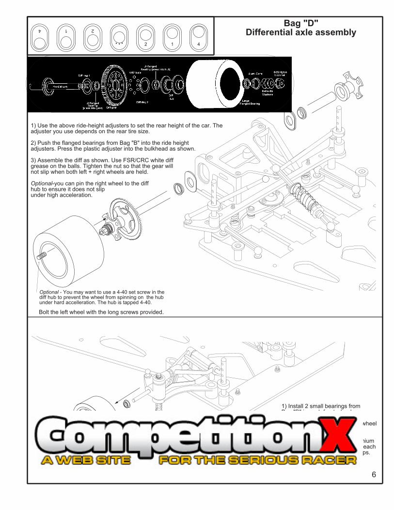
Bag "D"Differential axle assembly
1) Use the above ride-height adjusters to set the rear height of the car. The adjuster you use depends on the rear tire size.
2) Push the flanged bearings from Bag "B" into the ride heightadjusters. Press the plastic adjuster into the bulkhead as shown.
3) Assemble the diff as shown. Use FSR/CRC white diffgrease on the balls. Tighten the nut so that the gear willnot slip when both left + right wheels are held.
Optional-you can pin the right wheel to the diffhub to ensure it does not slipunder high acceleration.
1) Install 2 small bearings fromBag "B" in each front wheel.
2) Use an e-clip to fasten each wheel to the axle.
Optional - Use CRC# 4114 Titaniumstub axles w/ locknuts to fasten eachwheel. These eliminate the e-clips.
6
Optional - You may want to use a 4-40 set screw in thediff hub to prevent the wheel from spinning on the hubunder hard accelleration. The hub is tapped 4-40.
![The Cytology of Sitophilus [Calandra] oryzae (L.), S ... · The Cytology of Sitophilus [Calandra] oryzae ... and Some Other Rhynchophora (Coleoptera)1 Stanley G ... data concerning](https://static.fdocuments.in/doc/165x107/5b1585cd7f8b9a1a398ce5ff/the-cytology-of-sitophilus-calandra-oryzae-l-s-the-cytology-of-sitophilus.jpg)