Cahier technique no 149 - studiecd.dkstudiecd.dk/.../EMC_electromagnetic_compatibility.pdf ·...
36
.......................................................................... Collection Technique Cahier technique no. 149 EMC: electromagnetic compatibility J. Delaballe
Transcript of Cahier technique no 149 - studiecd.dkstudiecd.dk/.../EMC_electromagnetic_compatibility.pdf ·...

..........................................................................Collection Technique
Cahier technique no. 149
EMC: electromagnetic compatibility
J. Delaballe

"Cahiers Techniques" is a collection of documents intended for engineersand technicians, people in the industry who are looking for more in-depthinformation in order to complement that given in product catalogues.
Furthermore, these "Cahiers Techniques" are often considered as helpful"tools" for training courses.They provide knowledge on new technical and technological developmentsin the electrotechnical field and electronics. They also provide betterunderstanding of various phenomena observed in electrical installations,systems and equipments.Each "Cahier Technique" provides an in-depth study of a precise subject inthe fields of electrical networks, protection devices, monitoring and controland industrial automation systems.
The latest publications can be downloaded from the Schneider Electricinternet web site.Code: http://www.schneider-electric.comSection: Experts' place
Please contact your Schneider Electric representative if you want either a"Cahier Technique" or the list of available titles.
The "Cahiers Techniques" collection is part of the Schneider Electric’s"Collection technique".
ForewordThe author disclaims all responsibility subsequent to incorrect use ofinformation or diagrams reproduced in this document, and cannot be heldresponsible for any errors or oversights, or for the consequences of usinginformation and diagrams contained in this document.
Reproduction of all or part of a "Cahier Technique" is authorised with theprior consent of the Scientific and Technical Division. The statement"Extracted from Schneider Electric "Cahier Technique" no. ....." (pleasespecify) is compulsory.
Jacques DELABALLE
Ph.D University of Limoges in 1980, joined Merlin Gerin in 1986, afterseven years at Thomson.EMC laboratory manager at the Schneider Electric test center, he isalso a member of Committee 77 (Electromagnetic Compatibility) ofthe International Electrotechnical Commission (IEC).
no. 149EMC: electromagneticcompatibility
ECT 149(e) updated December 2001
Cahier Technique Schneider Electric no. 149 / p.2
Lexicon
Electromagnetic compatibility, EMC(abbreviation) (IEV 161-01-07)The ability of an equipment or system to functionsatisfactorily in its electromagnetic environmentwithout introducing intolerable electromagneticdisturbances to anything in that environment.
(Electromagnetic) compatibility level(IEV 161-03-10)The specified maximum disturbance level towhich a device, equipment or system operated inparticular conditions is likely to be subjected.
Note: In practice the electromagneticcompatibility level is not an absolute maximumlevel but may be exceeded by a small probability.
(Electromagnetic) disturbance(IEV 161-01-05)Any electromagnetic phenomenon which maydegrade the performance of a device, equipmentor system, or adversely affect living or inert matter.Note: An electromagnetic disturbance may be anelectromagnetic noise, an unwanted signal or achange in the propagation medium.
(Electromagnetic) susceptibility(IEV 161-01-21)The inability of a device, equipment or system toperform without degradation in the presence ofan electromagnetic disturbance.
Disturbance level(not defined in IEV 161)Level of an electromagnetic disturbance of agiven form, measured in particular conditions.
Disturbance limit(IEV 161-03-08)The maximum permissible electromagneticdisturbance level, measured in particularconditions.
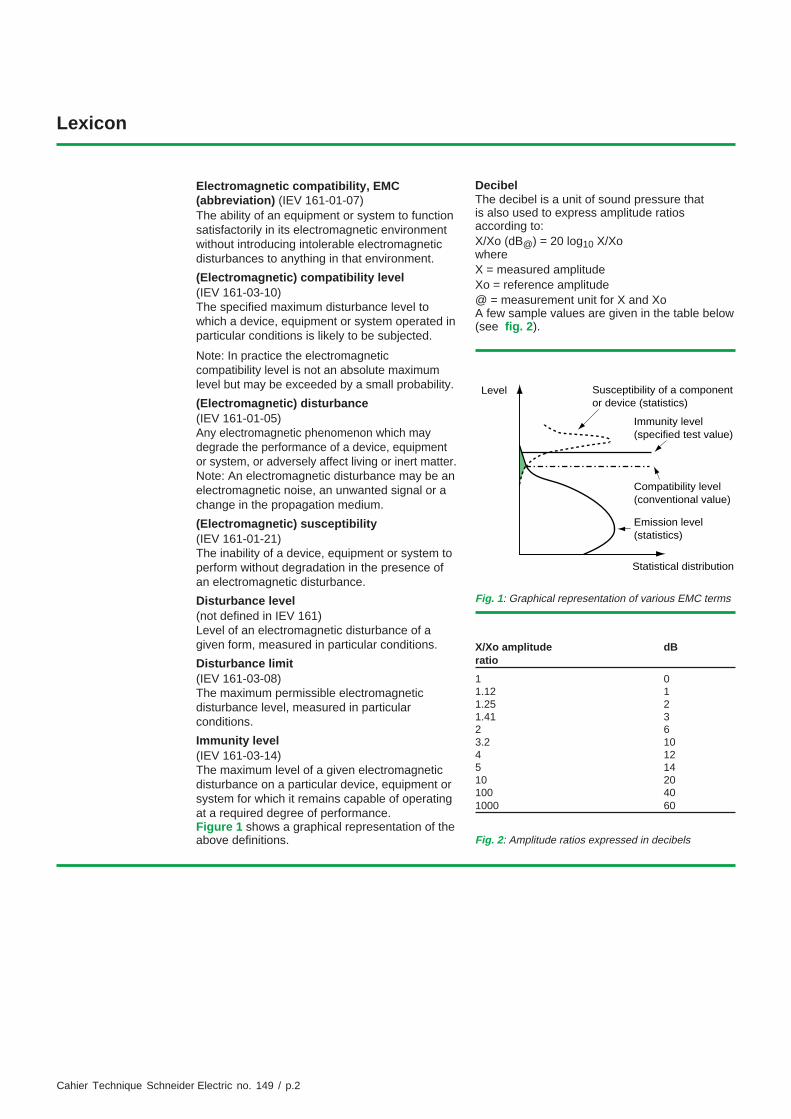
Immunity level(IEV 161-03-14)The maximum level of a given electromagneticdisturbance on a particular device, equipment orsystem for which it remains capable of operatingat a required degree of performance.Figure 1 shows a graphical representation of theabove definitions.
DecibelThe decibel is a unit of sound pressure thatis also used to express amplitude ratiosaccording to:X/Xo (dB@) = 20 log10 X/XowhereX = measured amplitudeXo = reference amplitude@ = measurement unit for X and XoA few sample values are given in the table below(see fig. 2).
Fig. 1: Graphical representation of various EMC terms
Susceptibility of a componentor device (statistics)
Immunity level(specified test value)
Compatibility level(conventional value)
Emission level(statistics)
Level
Statistical distribution
X/Xo amplitude dBratio
1 01.12 11.25 21.41 32 63.2 104 125 1410 20100 401000 60
Fig. 2: Amplitude ratios expressed in decibels
Cahier Technique Schneider Electric no. 149 / p.3
EMC: electromagnetic compatibility
Contents
1 Introduction 1.1 Electromagnetic compatibility - EMC - a characteristic p. 4and a discipline
1.2 Today, EMC is indispensable p. 4
1.3 EMC theory is complex p. 5
2 The source 2.1 The importance of identifying the source p. 6
2.2 An example of a continuous source of conducted p. 7disturbances in power electronics
2.3 An example of radiated disturbance sources: p. 8circuit closing in MV and VHV substations
3 Coupling 3.1 Different coupling modes exist p. 10
3.2 Common or differential mode field to wire coupling p. 10
3.3 Common impedance coupling p. 12
3.4 Differential mode wire to wire coupling or crosstalk p. 12
4 The victim 4.1 Equipment malfunction p. 14
4.2 Solutions to the problem p. 14
5 Installation 5.1 Installation is an important factor in the overall system EMC p. 17
5.2 Design phase p. 17
5.3 Installation phase p. 18
5.4 Practical examples p. 18
6 Standards, test facilities and tests 6.1 Standards p. 20
6.2 Test facilities p. 20
6.3 Tests p. 21
7 Conclusion p. 27
Appendix 1: Impedance of a conductor at high frequencies p. 28
Appendix 2: The different parts of a cable p. 29
Appendix 3: Tests performed at the Schneider Electric EMC laboratories p. 30
Appendix 4: Bibliography p. 31
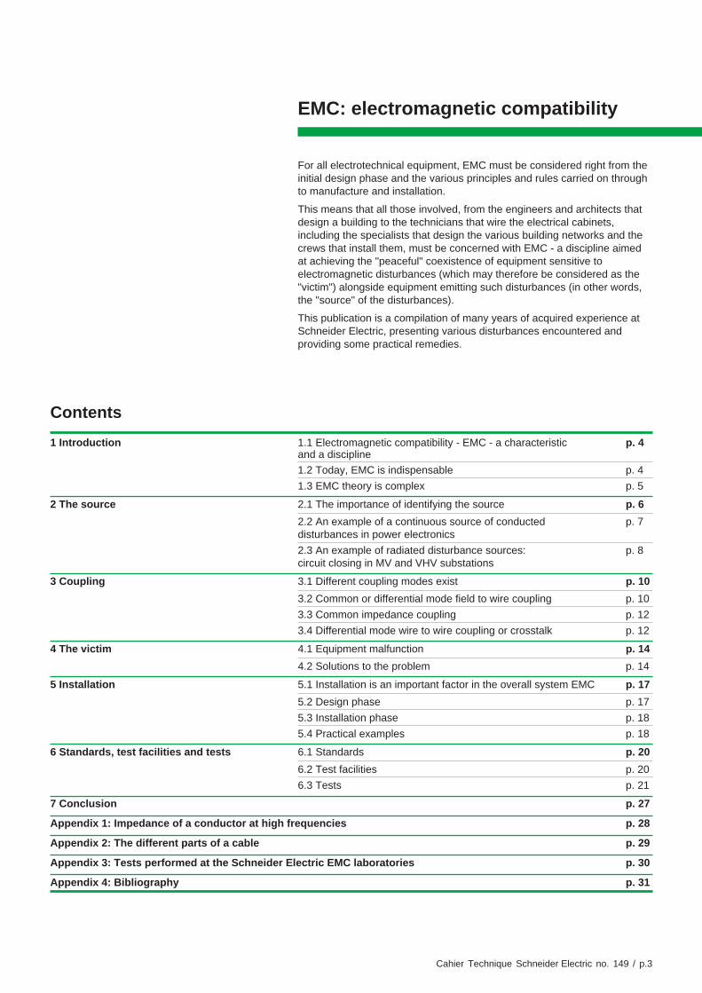
For all electrotechnical equipment, EMC must be considered right from theinitial design phase and the various principles and rules carried on throughto manufacture and installation.
This means that all those involved, from the engineers and architects thatdesign a building to the technicians that wire the electrical cabinets,including the specialists that design the various building networks and thecrews that install them, must be concerned with EMC - a discipline aimedat achieving the "peaceful" coexistence of equipment sensitive toelectromagnetic disturbances (which may therefore be considered as the"victim") alongside equipment emitting such disturbances (in other words,the "source" of the disturbances).
This publication is a compilation of many years of acquired experience atSchneider Electric, presenting various disturbances encountered andproviding some practical remedies.
Cahier Technique Schneider Electric no. 149 / p.4
1 Introduction
1.1 Electromagnetic compatibility - EMC - a characteristic and a discipline
EMC is a characteristic of equipment or systemsthat mutually withstand their respectiveelectromagnetic emissions.
According to the International ElectrotechnicalVocabulary IEV 161-01-07, EMC is the ability ofa device or system to function satisfactorily in itselectromagnetic environment without introducing
intolerable electromagnetic disturbances toanything in that environment.
EMC is now also a discipline aimed at improvingthe coexistence of equipment or systems whichmay emit electromagnetic disturbance and/or besensitive to them.
1.2 Today, EMC is indispensable
Equipment and systems are always subjectedto electromagnetic disturbance, and anyelectrotechnical equipment is, itself, moreor less an electromagnetic disturbance generator.
These disturbances are generated in manyways. However, the main underlying causes aresudden variations in current or voltage.
The most common electrical disturbances(see fig. 3) in the low voltage electrotechnicalfield are discussed in "Cahier Technique"no. 141. "Cahier Technique" no. 143 discussesdisturbances generated when operating mediumvoltage switchgear.
These disturbances can be propagated byconduction along wires or cables or by radiationin the form of electromagnetic waves.
Disturbances cause undesirable phenomena.Two examples are radio wave interference andinterference with control and monitoring systemscaused by electromagnetic emissions.
In recent years, several trends have togethermade EMC more important than ever:
c Disturbances are becoming stronger withincreasing voltage and current values.
c Electronic circuits are becoming increasinglysensitive.
c Distances between sensitive circuits (oftenelectronic) and disturbing circuits (power circuits)are becoming smaller.
In the development of its products, such as theMerlin Gerin protection switchgear as shown in
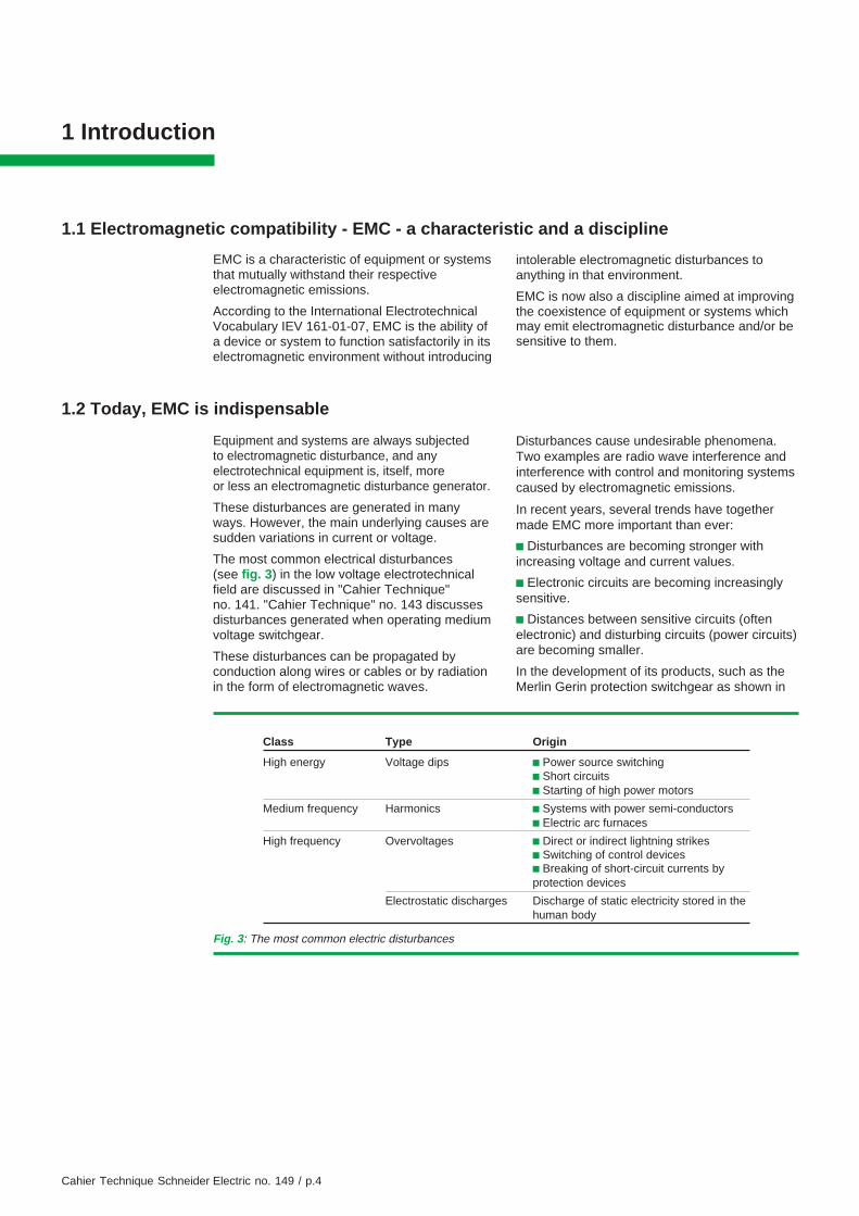
Fig. 3: The most common electric disturbances
Class Type Origin
High energy Voltage dips c Power source switchingc Short circuitsc Starting of high power motors
Medium frequency Harmonics c Systems with power semi-conductorsc Electric arc furnaces
High frequency Overvoltages c Direct or indirect lightning strikesc Switching of control devicesc Breaking of short-circuit currents byprotection devices
Electrostatic discharges Discharge of static electricity stored in thehuman body

Cahier Technique Schneider Electric no. 149 / p.5
figure 4, Schneider Electric foresaw thenecessity of understanding and applying EMCprinciples. In modern electrical switchgear andcontrol gear, low and high currents, control andpower electronics, electronic protection andelectric power devices all reside in closeproximity.
EMC is therefore a fundamental criterion thatmust be respected in all phases of productdevelopment and manufacture, as well as duringinstallation and wiring.
Moreover, EMC is now included in standardsand is becoming a legal requirement.The experience and achievements of SchneiderElectric are not limited to the satisfactoryoperation of electrical and/or electronicsystems in their usual electromagneticenvironment: for example, Merlin Gerin designsand builds equipment capable of withstandingthe harshest conditions such as electromagneticradiation generated by high-altitude nuclearblasts.
The necessary radiation hardening,i.e. improvement of the immunity of systemsexposed to electromagnetic pulses from nuclearsources, requires consideration of the mostadvanced EMC techniques.
Fig. 4: EMC application example: a medium-voltageSM6 panel containing a circuit breaker designed tointerrupt power (hundreds of amperes under tens ofkilovolts), and a SEPAM programmable control,monitoring and protection unit. The complete assemblymust remain operational under all circumstances.
1.3 EMC theory is complex
Any work involving EMC involves the analysis ofa three-component system:
c The disturbance generator or source
c Propagation or coupling
c The device or system affected or the victim
Strictly speaking, the three entities are notindependent but for all practical purposes areassumed to be.Note that installation, described in chapter 5,plays the most important role in the propagationof disturbances.
Theoretical analysis is difficult because it mustdeal with the propagation of electromagnetic
waves described by a set of complex differentialequations known as Maxwell’s equations.
Generally speaking, they cannot be solved toyield an analytical solution for real devices anddimensions. Even with powerful computersystems, a close numerical solution is oftenextremely difficult to obtain.
In practice, EMC problems must therefore bedealt with via simplifying assumptions, the use ofmodels and in particular conducting experimentsand taking measurements.

Cahier Technique Schneider Electric no. 149 / p.6
2 The source
2.1 The importance of identifying the source
The identification and measurement of thesource is essential since the type of source willdetermine which of the following measuresmust be taken:
c Limiting the disturbances generated (e.g. on acontactor, by installing an interferencesuppressing RC unit in parallel with the A.C.coil, or a diode on the D.C. coil)
c Avoiding cross-coupling (i.e. physicallyseparate two highly incompatible elements)
c Desensitizing potential victims (e.g. usingshielding)
Main causes
Any device or physical/electrical phenomenonthat emits an electromagnetic disturbance,either conducted or radiated, qualifies as asource.The main causes of electromagneticdisturbance are electric power distribution, radiowaves, electrostatic discharge and lightning.
c In electric power distribution, a large numberof disturbances are created by circuit switchingoperations:v In the low voltage field, the opening ofinductive circuits such as contactor coils,motors, solenoid valves etc. generates veryhigh surge voltages (up to several kV acrossthe coil terminals) that contain high-frequencyharmonics (ten to hundreds of MHz).v In the medium and high voltage fields, theopening and closing of disconnectors produceswaves with a very fast rate of rise (a fewnanoseconds). These waves are particularlyharmful to microprocessor-based systems.
c Radio waves emitted by remote monitoringsystems, remote controls, radiocommunications, television sets, walkie-talkiesetc. are, for some equipment, sources ofdisturbance in the order of several volts permeter. All of these disturbance emitters arenowadays increasingly common andsusceptible equipment must therefore beprovided with increasingly effective protection.
c An electrically-charged human body: forexample, a person walking on certain types ofcarpet in a cold and dry climate can be chargedup to more than 25 kV! Any contact withelectronic equipment produces a discharge witha very fast rise time (several nanoseconds)
which enters the device by conduction andradiation, generating a major disturbance.
Disturbance characteristics
Sources may be intentional (e.g. radiotransmitters) or not (e.g. arc welding units).However in general they can be distinguished bythe characteristics of the disturbances theyproduce:v Spectrumv Waveform, rise time or envelope of thespectrumv Amplitudev Energy
c The spectrum, i.e. the frequency band coveredby the disturbance can be very narrow, as in thecase of mobile telephones, or very wide, as forelectric arc furnaces.
Pulse type disturbances cover a particularly widespectrum extending up to 100 MHz or more (seefig. 5). To this last category belong almostexclusively sources such as:v Electrostatic dischargev Switching of relays, disconnectors, contactors,switches and circuit breakers in the LV, MV andHV rangev Lightningv Nuclear electromagnetic pulses (a specialdomain)
Since the degree of coupling is directlyproportional to frequency, EMC uses thefrequency domain to characterize disturbances.This type of representation, for a periodic signal,is similar to a Fourier series decomposition (as asum of harmonics).
c The waveform describes the characteristics ofthe disturbance over time and can, for example,be a damped sine wave or double exponentialfunction. It is expressed as a rise time tr, anequivalent frequency 0.35/tr or simply thedisturbance frequency for a narrow band signalor as a wavelength λ related to frequency byλ = c/f, where c is the speed of light (3 x 10⁸ ms-1).
c The amplitude is the maximum value the signalreaches in terms of voltage (Volts), electric field(Volts/meter), etc.
c The energy is the integral of the instantaneousenergy over the time the disturbance lasts(Joules).

Cahier Technique Schneider Electric no. 149 / p.7
Fig. 5: Examples of spectral characteristics of disturbances
0
TFrequency1/T
0
Amplitude ofdisturbance
Time
Spectraldensity Narrow band
Radio wave
0 0
Amplitude ofdisturbance
Time
Indirect lightning effect
tr
Wide band
Spectraldensity
0.35 / tr Frequency
2.2 An example of a continuous source of conducted disturbance in power electronics
In power electronics, the principal sources ofdisturbance tend to be voltage rather thancurrent transients. The voltages can vary byhundreds of volts in a matter of a fewnanoseconds giving dV/dts in excess of 109 V/s.Pulse Width Modulation (PWM) (see fig. 6), forexample, used to generate a sine wave voltagefrom a D.C. voltage, works with voltage changes
from 0 to Udc (660 V for rectified three-phase)occurring in a very short time, nano tomicroseconds depending on the technologyused.Rapid voltage changes are the source of variousdisturbance phenomena, the most problematic ofwhich is, based on experience, the generation ofcurrents flowing through any stray capacitances.
U
Udc
Uact
Udc
tr tf
t
Uac curve
(part of sine wave)
Fig. 6: A source of disturbance in power electronics equipment: the technique of switching by pulse widthmodulationa: Principleb: A considerably enlarged impulse (expanded scale for t); the part of the sine wave is disproportionate since itcovers 20 ms; tr ≈ 2 to 3 tf (10 ns to 1 µs)
a) b)
Cahier Technique Schneider Electric no. 149 / p.8
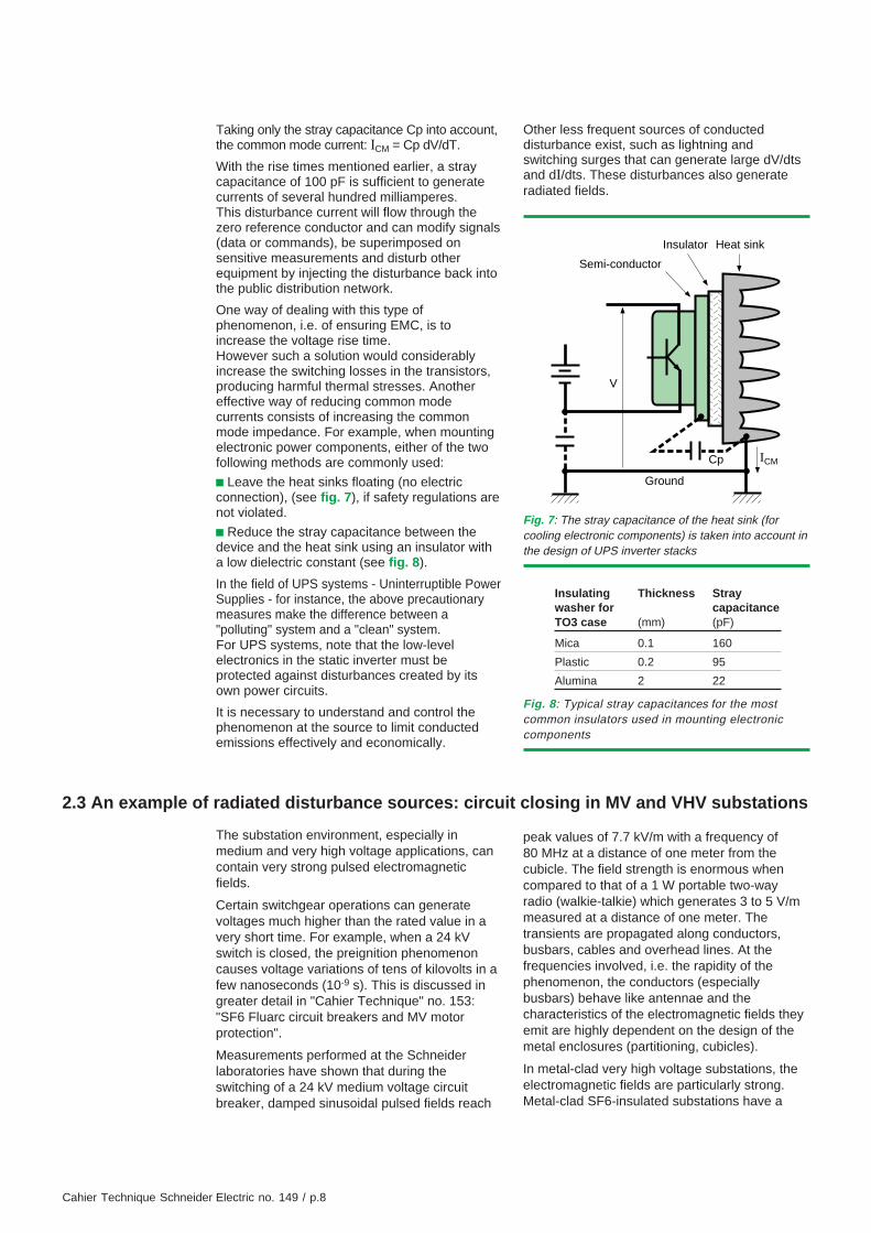
Taking only the stray capacitance Cp into account,the common mode current: ICM = Cp dV/dT.
With the rise times mentioned earlier, a straycapacitance of 100 pF is sufficient to generatecurrents of several hundred milliamperes.This disturbance current will flow through thezero reference conductor and can modify signals(data or commands), be superimposed onsensitive measurements and disturb otherequipment by injecting the disturbance back intothe public distribution network.
One way of dealing with this type ofphenomenon, i.e. of ensuring EMC, is toincrease the voltage rise time.However such a solution would considerablyincrease the switching losses in the transistors,producing harmful thermal stresses. Anothereffective way of reducing common modecurrents consists of increasing the commonmode impedance. For example, when mountingelectronic power components, either of the twofollowing methods are commonly used:
c Leave the heat sinks floating (no electricconnection), (see fig. 7), if safety regulations arenot violated.
c Reduce the stray capacitance between thedevice and the heat sink using an insulator witha low dielectric constant (see fig. 8).
In the field of UPS systems - Uninterruptible PowerSupplies - for instance, the above precautionarymeasures make the difference between a"polluting" system and a "clean" system.For UPS systems, note that the low-levelelectronics in the static inverter must beprotected against disturbances created by itsown power circuits.
It is necessary to understand and control thephenomenon at the source to limit conductedemissions effectively and economically.
Other less frequent sources of conducteddisturbance exist, such as lightning andswitching surges that can generate large dV/dtsand dI/dts. These disturbances also generateradiated fields.
2.3 An example of radiated disturbance sources: circuit closing in MV and VHV substations
Fig. 7: The stray capacitance of the heat sink (forcooling electronic components) is taken into account inthe design of UPS inverter stacks
Cp ICM
V
Ground
Semi-conductor
Insulator Heat sink
Fig. 8: Typical stray capacitances for the mostcommon insulators used in mounting electroniccomponents
Insulating Thickness Straywasher for capacitanceTO3 case (mm) (pF)
Mica 0.1 160
Plastic 0.2 95
Alumina 2 22
The substation environment, especially inmedium and very high voltage applications, cancontain very strong pulsed electromagneticfields.
Certain switchgear operations can generatevoltages much higher than the rated value in avery short time. For example, when a 24 kVswitch is closed, the preignition phenomenoncauses voltage variations of tens of kilovolts in afew nanoseconds (10-9 s). This is discussed ingreater detail in "Cahier Technique" no. 153:"SF6 Fluarc circuit breakers and MV motorprotection".
Measurements performed at the Schneiderlaboratories have shown that during theswitching of a 24 kV medium voltage circuitbreaker, damped sinusoidal pulsed fields reach
peak values of 7.7 kV/m with a frequency of80 MHz at a distance of one meter from thecubicle. The field strength is enormous whencompared to that of a 1 W portable two-wayradio (walkie-talkie) which generates 3 to 5 V/mmeasured at a distance of one meter. Thetransients are propagated along conductors,busbars, cables and overhead lines. At thefrequencies involved, i.e. the rapidity of thephenomenon, the conductors (especiallybusbars) behave like antennae and thecharacteristics of the electromagnetic fields theyemit are highly dependent on the design of themetal enclosures (partitioning, cubicles).
In metal-clad very high voltage substations, theelectromagnetic fields are particularly strong.Metal-clad SF6-insulated substations have a

Cahier Technique Schneider Electric no. 149 / p.9
coaxial shape and therefore display a constantcharacteristic impedance. Rapid voltagechanges inside the tubular metal enclosuresgenerate standing wave phenomena. They arecreated by reflections occurring at impedancemismatches due to conic outgoing feedthroughsthat cross the shielding for example. Themagnitude and duration of the phenomenon isalso increased by this effect.
The electronic environment at medium and veryhigh voltages requires in-depth electromagneticcompatibility studies for the design andinstallation of relay systems and control andmonitoring devices. This is particularly importantbecause in addition to the radiated disturbances,conducted voltage transients are also generatedin substations as discussed at the beginning ofthis section (see fig. 9).
Fig. 9: Three examples of devices with digitalelectronics developed by Schneider Electric anddesigned taking full consideration of EMC research.a: A SEPAM protection and control unit integrated inMV equipment (Merlin Gerin brand)b: A protection and control unit for Masterpact LVcircuit-breakers (Merlin Gerin brand)c: An ATV variable speed drive (Telemecaniquebrand)
a) b)
c)

Cahier Technique Schneider Electric no. 149 / p.10
3 Coupling
3.1 Different coupling modes exist
Coupling refers to the linking, transfer ortransmission of electromagnetic disturbancesfrom an emitter to a victim.
Coupling is expressed in terms of a couplingcoefficient k, expressed in dB (e.g. -75 dB),which can be seen as the transmission efficiencyof the disturbance from the emitter to thepotential victim(k = 20 log A (received)/A (transmitted), where Ais the amplitude of the disturbance).
It is important to define this coefficient for EMCsince the lower the coefficient (the larger itsabsolute value in decibels) the weaker the
disturbance voltage received by the victim andthe better the EMC.
This coefficient k is only meaningful when thetransfer of electromagnetic disturbances isproportional to frequency, which is often the casein practice.Three well known coupling modes can bedistinguished:c Common and differential mode field-to-wirecouplingc Common impedance couplingc Differential mode wire-to-wire coupling orcrosstalk
3.2 Common or differential mode field-to-wire coupling
An electromagnetic field can couple into any kindof wire-like structure and generate eithercommon mode (with respect to ground) ordifferential mode (between wires) voltages or, asis generally the case, both. This type of couplingis called field-to-wire coupling and is also knownas the antenna effect of wiring, printed circuitboard tracks, etc.
c Common mode coupling generates commonmode disturbance voltages or currents.
A conducted common mode voltagedisturbance (VCM) is a voltage that affects alllive conductors.
It is referenced to chassis or earth ground(typically in electrical systems): all commonmode isolation tests on low voltage circuitbreakers are therefore performed between earthground and all phases.
A common mode current (ICM) is a current thatflows through all live conductors in the samedirection (see fig. 10). The current induced in aLV line by a lightning impulse is a common modecurrent.
c Differential mode coupling involves voltagesand currents in the classic sense, for example,between two phases of a circuit breaker or
Fig. 10: Common mode voltage and current between two relays of a low voltage compartment in a mediumvoltage cubicle
PE
VCM
ICM
ICMDisturbancegenerator
CpCp

Cahier Technique Schneider Electric no. 149 / p.11
between two wires which transmit sensor datato the electronics.
The equations that govern the coupling betweenthe electromagnetic field (impedance of anarbitrary wave) and a wire-like structure (whichcan also be arbitrary) are very complex. In mostcases they can neither be solved analytically nornumerically.
Nonetheless, one of the simpler and mostcommon types of coupling can be expressedanalytically: the coupling between the magneticcomponent of an electromagnetic field and aloop of area A formed by the conductors(see fig. 11).The magnetic component H of the field inducesin the loop a series voltage equal to:e = µ0 'A' dH/dt
where µ0 = the permeability in vacuum(4π 10-7 H/m)
For example, in a medium voltage substation,a loop (of wire or cable) covering 100 cm2
placed 1 m from the cubicle (see fig. 12)and exposed to a pulsed field of 5.5 kVrms/m(laboratory measurement) will generate(by induction) a series transient voltage of 15 V.
The above equation holds as long as the largestdimension of the loop does not exceed a tenth
of the wavelength of the disturbance. Note thatsuch a green/yellow wire loop (see fig. 12) iseasily created in the "relay compartment" whenthe wires are connected in a star configuration toground.
Fig. 12: Example of a ground loop in a low voltage compartment of a medium voltage cubicle
0 volt
Cubicle ground
0 volt
Fig. 11: An example of differential mode field-to-wirecoupling
E
H
e
Electromagneticfield
e = voltage induced by theelectromagnetic field
Surface exposedto electromagneticfield
Cahier Technique Schneider Electric no. 149 / p.12
3.3 Common impedance coupling
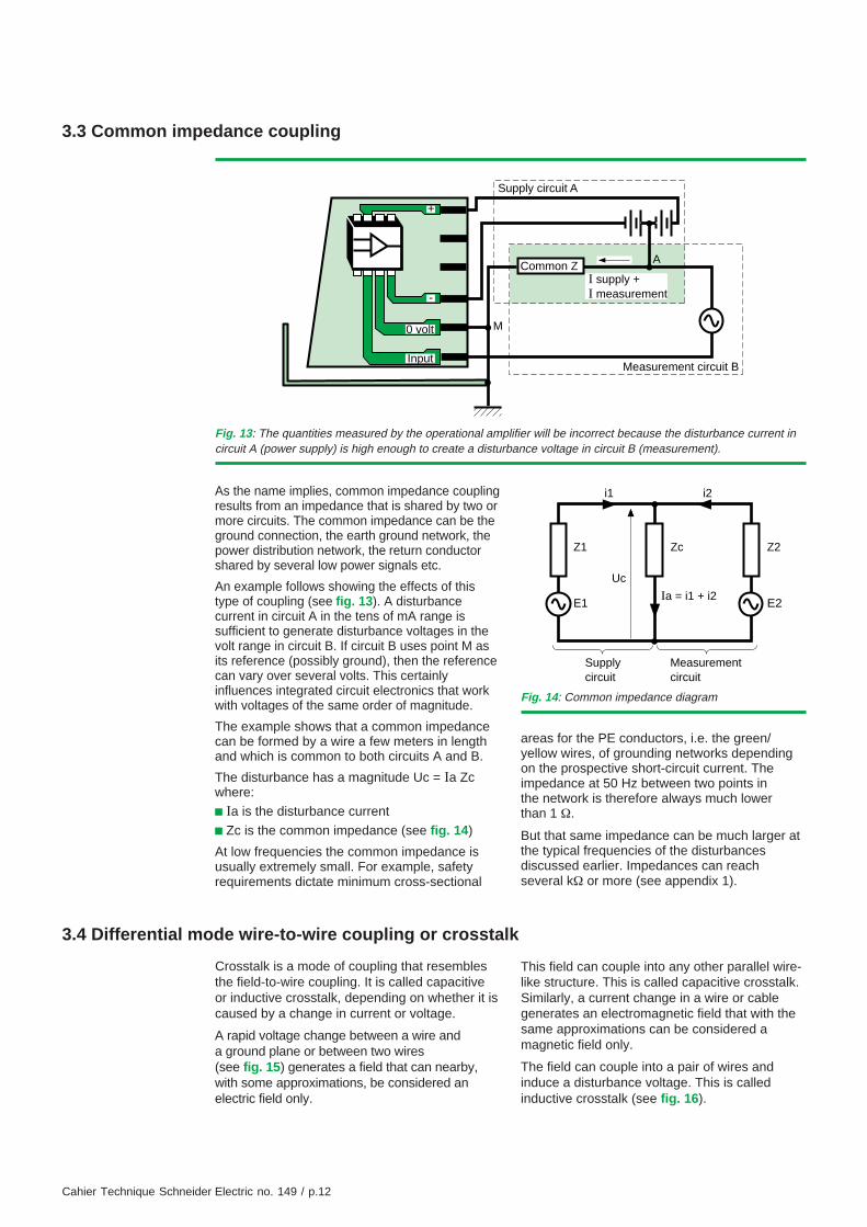
As the name implies, common impedance couplingresults from an impedance that is shared by two ormore circuits. The common impedance can be theground connection, the earth ground network, thepower distribution network, the return conductorshared by several low power signals etc.
An example follows showing the effects of thistype of coupling (see fig. 13). A disturbancecurrent in circuit A in the tens of mA range issufficient to generate disturbance voltages in thevolt range in circuit B. If circuit B uses point M asits reference (possibly ground), then the referencecan vary over several volts. This certainlyinfluences integrated circuit electronics that workwith voltages of the same order of magnitude.
The example shows that a common impedancecan be formed by a wire a few meters in lengthand which is common to both circuits A and B.
The disturbance has a magnitude Uc = Ia Zcwhere:
c Ia is the disturbance current
c Zc is the common impedance (see fig. 14)
At low frequencies the common impedance isusually extremely small. For example, safetyrequirements dictate minimum cross-sectional
Fig. 13: The quantities measured by the operational amplifier will be incorrect because the disturbance current incircuit A (power supply) is high enough to create a disturbance voltage in circuit B (measurement).
+
0 volt
A
M
Input
I supply +I measurement
Measurement circuit B
Common Z
Supply circuit A
-
Fig. 14: Common impedance diagram
Ia = i1 + i2E1 E2
Uc
Z1 Zc Z2
i1 i2
Supplycircuit
Measurementcircuit
areas for the PE conductors, i.e. the green/yellow wires, of grounding networks dependingon the prospective short-circuit current. Theimpedance at 50 Hz between two points inthe network is therefore always much lowerthan 1 Ω.
But that same impedance can be much larger atthe typical frequencies of the disturbancesdiscussed earlier. Impedances can reachseveral kΩ or more (see appendix 1).
3.4 Differential mode wire-to-wire coupling or crosstalk
Crosstalk is a mode of coupling that resemblesthe field-to-wire coupling. It is called capacitiveor inductive crosstalk, depending on whether it iscaused by a change in current or voltage.
A rapid voltage change between a wire anda ground plane or between two wires(see fig. 15) generates a field that can nearby,with some approximations, be considered anelectric field only.
This field can couple into any other parallel wire-like structure. This is called capacitive crosstalk.Similarly, a current change in a wire or cablegenerates an electromagnetic field that with thesame approximations can be considered amagnetic field only.
The field can couple into a pair of wires andinduce a disturbance voltage. This is calledinductive crosstalk (see fig. 16).

Cahier Technique Schneider Electric no. 149 / p.13
Capacitive and inductive crosstalk existswhenever conductors are routed in parallel orreside in close proximity to each other.Crosstalk can occur in cableways and troughs andespecially between power cables carrying high-frequency disturbances differentially and twistedpairs used by digital networks such as Batibus.The crosstalk will be stronger the longer theparallel paths, the smaller the distance betweenwires or pairs of wires and the higher thefrequency of the disturbances.For example, using the notation in figure 15, thevoltage coupling coefficient (capacitive crosstalk)can be expressed as:
VV
j 2 C
j 2
N
1
=+
++( )
π
π
fC C
fR C C
12
12 20
12 20
1
where:c V1: voltage sourcec VN: disturbance voltage induced by couplingc C12: coupling capacitance between two wireswhich is proportional to the wire length and thedistance coefficient Log [1 + (h/e)2] where h isthe distance between the two wires of the pairand e the distance between pairsc C20: leakage capacitance between the twowires of the disturbed pairc R: load impedance of the disturbed pairIn this formula, the first term in the denominatoris often negligible as compared to the secondterm. Consequently a reasonable approximationwould be:
VV
CC C
R C C
N f1
12
12 20
12 20
2 1
≈+
+( )π
= 2 12πf R C
= ω R C12
To be more specific, consider two pairs withwires of 0.65 mm diameter running 10 meters inparallel; the wires in the "victim" pair are 1 cmapart and the pairs 2 cm away from each otherand R = 1 kΩ. For a 1 MHz signal, a couplingcoefficient of - 22 dB is found, and furthercalculation gives the result:
VVN
1
112
=
Fig. 15: A rapid change in V1 creates a field which at ashort distance can be assumed to be purely electricand induces a voltage VN in another wire-like structurewhich runs in parallel; this mode of coupling is calledcapacitive crosstalk.
e
V1
h
h
R
VNC20
C12
Fig. 16: A current change in the cable generates anelectromagnetic field which at a short distance can beconsidered to be purely magnetic and induces adisturbance (voltage) in wires that form a loop; thismode of coupling is called inductive crosstalk.
H
I
Powercable
Pair of wires(low level)
e
In practice, capacitive and inductive coupling ofthis type is considerably reduced by the use oftwisted pairs and shielded cables.

Cahier Technique Schneider Electric no. 149 / p.14
4 The victim
Any equipment that may be affected by adisturbance can be considered as a "victim".It is typically equipment containing some
4.1 Equipment malfunction
Equipment malfunctions are divided into fourcategories and can be:c permanent and measurablec random and non-repetitive, appearing whenthe disturbances appearc random and non-repetitive, remaining after thedisturbances vanishc permanent equipment failure (componentsphysically destroyed)
The above types characterize the duration of thefault but not its severity.
The severity of a fault is a matter of functionalityor, in other words how critical the equipment is.Certain malfunctions may be acceptable for alimited time such as the temporary loss of adisplay; others may not be acceptable such assecurity equipment malfunctions.
4.2 Solutions to the problem
Numerous solutions in terms of how equipmentis to be built exist to provide effective and low-cost immunity to electromagnetic disturbances.Precautionary measures can be taken in:c The design of printed circuit boards (functionalpartitioning, trace layouts, interconnects)c The choice of electronic componentsc The choice and design of protective coveringc The ground interconnectionsc The wiring
The choices involve many different disciplinesand should be made during the design phase ofa project to avoid additional costs which arealways high for modifications after the design iscompleted or when the product is already on themarket.Implementation of all these precautionarymeasures requires know-how which goes farbeyond the standard filtering and shieldingtechniques often recommended to increaseimmunity even if their effectiveness has not beenproven.
Printed circuit boardsThe designer of printed circuit boards mustfollow certain rules that concern functionalpartitions and layout.
Starting with component placement, it is alreadypossible to reduce coupling effects related toproximity.
For example, the grouping together of elementsthat belong to the same circuit category (digital,analog, or power circuits) according to theirsusceptibility, reduces interference.
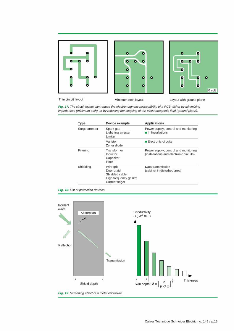
Furthermore, the layout of circuit board traces(routing) has a dramatic effect on susceptibility:the same electrical schematic implemented indifferent ways can display orders of magnitudewith different immunity levels.For example, a "minimum etch" circuit boardlayout (see fig. 17) reduces radiation effects andsensitivity.
Electronic devicesNumerous components are available to provideeffective protection against conducteddisturbances. Selection is guided by the powerlevel of the circuit to protect (power supply, controland monitoring, etc.) and the type of disturbance.Consequently, for common mode disturbances ina power circuit, a transformer will be used if thedisturbances are at low (< 1 kHz) frequencies anda filter if they are at high frequencies.
The table in figure 18 gives a non-exhaustive listof protection devices. They have differentcharacteristics: a filter does not protect againstsurges, and a surge protector does not protectagainst high frequency disturbances.
ShieldingEnclosing sensitive equipment in a conductiveshield provides protection againstelectromagnetic fields. To be effective, thethickness of the conductive shield must exceedthe skin depth at the frequencies of thedisturbance encountered (see fig. 19).Against a high-frequency disturbance or anelectric field, a conductive varnish can be efficient.Only a high-permeability material enclosure canstop low-frequency magnetic fields.
electronics which malfunction because ofelectromagnetic disturbances occurring in anunexpected frequency band.
Cahier Technique Schneider Electric no. 149 / p.15
Fig. 17: The circuit layout can reduce the electromagnetic susceptibility of a PCB: either by minimizingimpedances (minimum etch), or by reducing the coupling of the electromagnetic field (ground plane).
Fig. 18: List of protection devices
Fig. 19: Screening effect of a metal enclosure
Conductivityσ ( Ω-1 m-1 )
Transmission
Absorption
Skin depth : δ = 2
µ σ ω
12
Incidentwave
Reflection
Shield depthThickness
Type Device example Applications
Surge arrester Spark gap Power supply, control and monitoringLightning arrester c In installationsLimiter
Varistor c Electronic circuitsZener diode
Filtering Transformer Power supply, control and monitoringInductor (installations and electronic circuits)CapacitorFilter
Shielding Wire grid Data transmissionDoor braid (cabinet in disturbed area)Shielded cableHigh frequency gasketCurrent finger
0 volt
Thin circuit layout Minimum etch layout Layout with ground plane

Cahier Technique Schneider Electric no. 149 / p.16
Ground interconnections
When it comes to grounding, good electricalcontinuity between different parts of the housingis extremely important. They must be carefullyand correctly interconnected, for exampleprotecting contact areas from any paint and alsoby using short, wide wire braids(to reduce impedance to a minimum).
Cabling
Cable shielding is an extension of the conductiveenvelope placed around sensitive systems.It therefore has the shortest possible connectionand if possible all around its perimeter to protectagainst high-frequency disturbances.
Just as with the coupling between anelectromagnetic field and a wire-like structure(see section 3), the theory governing wireshielding is very complex and too vast to becovered in this paper. References to specialliterature are given in the bibliography.
When all design and manufacturing rules arerespected, the system will be sufficiently immuneto electromagnetic disturbances in theenvironment it was built for.
Nevertheless, this immunity can only bevalidated by actual measurements thatdetermine the effectiveness of different shieldingtechniques. At Schneider Electric, for example,different prototype models of electronic trip unitsfor circuit breakers are exposed to rigorous testsrepresentative of the largest disturbances towhich they are likely to be subjected.
The true objective of these tests is to check thatthe trip unit does not operate inadvertently andthat the circuit breaker opens correctly and in therequired time.
The "product" standards now include thesespecifications, for example: IEC 60947-2standard concerning industrial circuit breakers,and a revised IEC 61131-2 concerningprogrammable logic controllers.
Cahier Technique Schneider Electric no. 149 / p.17
5 Installation
5.1 Installation is an important factor in the overall system EMC
Evidence of this fact can be found in theNF C 15-100 (IEC 60364) general LV installationstandards which devotes an entire chapter (33)to electromagnetic compatibility.
The two previous sections have shown thatinstallation plays an important role in EMC; thisis true for both the design and layout phase andthe actual installation phase.
5.2 Design phase
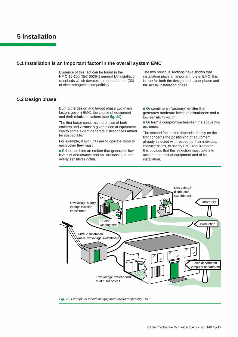
During the design and layout phase two majorfactors govern EMC: the choice of equipmentand their relative locations (see fig. 20).
The first factor concerns the choice of bothemitters and victims: a given piece of equipmentcan to some extent generate disturbances and/orbe susceptible.
For example, if two units are to operate close toeach other they must:
c Either combine an emitter that generates lowlevels of disturbance and an "ordinary" (i.e. notoverly sensitive) victim.
c Or combine an "ordinary" emitter thatgenerates moderate levels of disturbance and alow-sensitivity victim.c Or form a compromise between the above twoextremes.
The second factor that depends directly on thefirst concerns the positioning of equipment,already selected with respect to their individualcharacteristics, to satisfy EMC requirements.It is obvious that this selection must take intoaccount the cost of equipment and of itsinstallation.
Fig. 20: Example of electrical equipment layout respecting EMC
Low voltagedistributionswitchboard
MV/LV substationmain low voltage switchboard
Low voltage supplythrough isolationtransformer
Laboratory
Production
Low voltage switchboard& UPS for offices
Sales departmentComputer department
Electricwelding sets

Cahier Technique Schneider Electric no. 149 / p.18
5.3 Installation phase
Electrical and electronic installation work shouldfollow the guidelines already discussed inprevious sections. In practice, the differentcoexistent coupling modes must be studied andreduced to satisfy the EMC requirements.
Different techniques should be applied:c The circuits and the chassis/earth groundsmust be laid out in a grid.c The circuits must be physically separated.c The wiring must be carefully planned.
5.4 Practical examples
Grid layout for circuits and chassis/earthgroundsToday, equipment can be susceptible to very lowenergy levels. It contains interconnectedelectronics sensitive to high frequencies.Common impedance coupling frequently occursand to avoid it, the best possible equipotentialgrounding system or to be more precise aground grid, is essential.
This is the first step in providing protectionagainst disturbance problems. In a factory powerdistribution network, all protection (PE) wiresmust be joined together and connected to theexisting metal structures as specified inNF C 15-100 (see fig. 21).
Similarly, within equipment, all grounds andframes must be connected to a grid-likegrounding system in the shortest possible wayusing low impedance (at high frequencies), wideand short electrical connections (wires or braids).The wiring of an electrical cabinet is a typicalexample: all grounds must be connectedtogether.
There is a change to be noted here: the methodinvolving the connection of all grounds to acentral point (star configuration), sometimesused for analog electronic equipment sensitive to50 Hz hum, has been replaced by grids whichare far more effective in reducing disturbancesthat affect today's digital systems, protectionrelays and control and monitoring systems.
Separation of electrical circuits
This technique consists of separating the energysources (usually 50 or 60 Hz). The aim is toavoid interference on a sensitive device causedby conducted disturbances generated by othersystems connected to the same power source.The principle is to create two separate powersources isolated by impedances that are high atthe frequency of the disturbances.
Transformers (not auto-transformers) areeffective isolators, especially at low frequencies:MV/LV transformers, isolation transformers andany input transformer for electronics stopconducted disturbances.
Sometimes an isolating filter is required toeliminate high frequency disturbances. If thesensitive equipment also requires emergencypower, it can be supplied by an uninterruptiblepower supply (UPS) as long as the UPS containsthe required isolation transformer(s).
Well-designed wiring
The effects of the three coupling mechanismsdiscussed earlier can be reduced if the wire andcable routing adheres to the following rules:
c In all systems that cannot be separatedphysically for economic reasons, wires/cablesmust be grouped together by category. Thedifferent categories should be routed separately:in particular, power cables should be on one side
Fig. 21: The grids for circuits and for chassis/earth grounding systems are often combined in electrical cabinets
PEPE
M
Cahier Technique Schneider Electric no. 149 / p.19
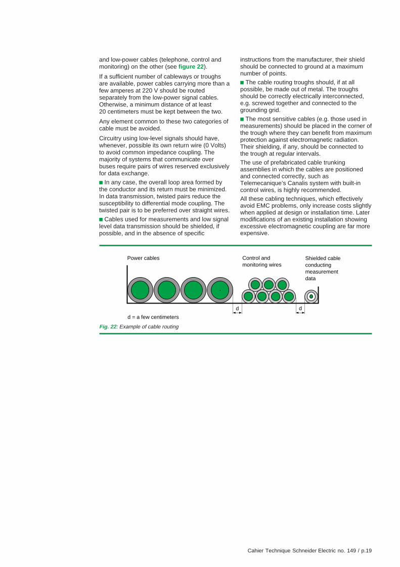
and low-power cables (telephone, control andmonitoring) on the other (see figure 22).
If a sufficient number of cableways or troughsare available, power cables carrying more than afew amperes at 220 V should be routedseparately from the low-power signal cables.Otherwise, a minimum distance of at least20 centimeters must be kept between the two.
Any element common to these two categories ofcable must be avoided.
Circuitry using low-level signals should have,whenever, possible its own return wire (0 Volts)to avoid common impedance coupling. Themajority of systems that communicate overbuses require pairs of wires reserved exclusivelyfor data exchange.
c In any case, the overall loop area formed bythe conductor and its return must be minimized.In data transmission, twisted pairs reduce thesusceptibility to differential mode coupling. Thetwisted pair is to be preferred over straight wires.
c Cables used for measurements and low signallevel data transmission should be shielded, ifpossible, and in the absence of specific
instructions from the manufacturer, their shieldshould be connected to ground at a maximumnumber of points.
c The cable routing troughs should, if at allpossible, be made out of metal. The troughsshould be correctly electrically interconnected,e.g. screwed together and connected to thegrounding grid.
c The most sensitive cables (e.g. those used inmeasurements) should be placed in the corner ofthe trough where they can benefit from maximumprotection against electromagnetic radiation.Their shielding, if any, should be connected tothe trough at regular intervals.
The use of prefabricated cable trunkingassemblies in which the cables are positionedand connected correctly, such asTelemecanique’s Canalis system with built-incontrol wires, is highly recommended.
All these cabling techniques, which effectivelyavoid EMC problems, only increase costs slightlywhen applied at design or installation time. Latermodifications of an existing installation showingexcessive electromagnetic coupling are far moreexpensive.
Fig. 22: Example of cable routing
dd
Power cables Shielded cableconductingmeasurementdata
Control andmonitoring wires
d = a few centimeters
Cahier Technique Schneider Electric no. 149 / p.20
6 Standards, test facilities and tests
6.1 Standards
Documented standards that regulateelectromagnetic compatibility of systems havelong been in existence.
The first regulations were issued by the CISPR,Comité International Spécial des PerturbationsRadioélectriques (International SpecialCommittee on Radio Interference). Theseregulations covered only the maximumacceptable power level that could be emitted bydifferent types of equipment, mainly to protectradio transmission and reception.
National Committees and the InternationalElectrotechnical Commission (IEC) have issueddocumented standards that cover all aspects ofEMC emission and susceptibility encountered inthe civilian domain.
Military standards on EMC have been compiledin the GAM EG 13 series in France and in theMIL-STD series in the United States.The increasing importance of EMC and theforthcoming unification of Europe are changingthe landscape of civilian standards.
The European Council published a Directive(reference 89/336/EC) in May 1989 on thissubject. It relates to unifying the EMC legislationof the member countries. Every member countryis committed to include it in its national legislationand make its use and application mandatory.
The European Directive not only imposes limitson emitted disturbances but also sets theminimum immunity to electromagneticdisturbances. The Directive makes reference tostandards that define maximum disturbancelevels.
Technical Committees were established byCENELEC, Comité Européen de NormalisationElectrotechnique (European Committee forElectrotechnical Standardization). They gatheredexisting standards which correspond toapplication of the Directive, and drew up those
standards which were missing. The TechnicalCommittee TC 210 based its work on actualindustrial practice.
For emission tests, the German standardsVDE 0871 and VDE 0875 were used for sometime as a reference. These are now replaced bythe recent European standards EN 55011 andEN 55022. The reference standards for EMC arenow the IEC 61000 series (formerly IEC 1000).The publication contains several parts, forexample:
c 61000-1: Application, definitions
c 61000-2: Environment, compatibility levels
c 61000-3: Disturbance limits
c 61000-4: Testing and measuring techniques
c 61000-5: Installation and mitigation guidelines
c 61000-6: Generic standards
Part 4 contains several sections relating toimmunity tests, including:v 1 - Overview of immunity testsv 2 - Electrostatic dischargev 3 - Radiated, radio-frequency electromagneticfieldsv 4 - Electrical fast transient/burstsv 5 - Surgesv 6 - Conducted disturbances > 9 kHzv 7 - Harmonicsv 8 - Power frequency magnetic fieldsv 9 - Pulse magnetic fieldsv 10 - Damped oscillatory magnetic fieldv 11 - Voltage dips, short interruptions andvoltage variationv 12 - Oscillatory wavesv 13 - Harmonics and interharmonicsv etc.
These standards are widely accepted in theinternational community and Schneider Electrichas adopted them for its products. The followingsection describes in more detail the tests thatrelate to these standards.
6.2 Test facilities
As mentioned before, to respect regulations,standardized measurements and tests must alsobe performed.Due to its business applications, SchneiderElectric made EMC one of its major concerns
long ago. Large installations such as Faradaycages have been in use since the seventies.
For many years, Schneider Electric has had twoEMC laboratories. These centers make full useof our skills and knowledge and promote the

Cahier Technique Schneider Electric no. 149 / p.21
exchange of information. They also offerservices to outside customers. Thus theconducted tests cover a wide range of EMCapplications, with:c electrostatic discharge testsc conducted and radiated immunity testsc conducted and radiated emission testsAs with any other measurements,electromagnetic compatibility measurementsmust be reproducible both in time and in space,which means that two measurements performed
at two different laboratories must yield the sameresults. In the EMC discipline, this means largefacilities requiring considerable investment and astrict quality policy.The quality program at the Schneider ElectricEMC laboratories is based on a Quality Manualand a set of procedures. These proceduresconcern calibration and the connection tocalibrated standards in addition to each type ofmeasurement itself. The list of tests forstandards that can be performed at thelaboratories appears in appendix 3.
6.3 Tests
Electrostatic discharge
These tests are designed to check the immunityof circuit boards, equipment and systems toelectrostatic discharge.
Electrostatic discharges are the result of chargesaccumulated by a person, for example, walkingon a floor covered with an electrically insulatingmaterial. When the person touches anelectrically conducting material connected via animpedance to ground, he discharges suddenlythrough the impedance. Several studies haveshown that the waveform is a function of thecharacteristics of the emitter (the source of thedischarge) and of the circuits involved, but alsoof other parameters such as relative humidity(see fig. 23) or the speed at which the chargedbody approaches, in our example the hand ofthe person, etc.
This research has led to standardized dischargetests. They are performed with an electrostaticgun that simulates a human being inpredetermined configurations (see fig. 24).
Fig. 23: The effect of relative humidity on the electrostaticdischarge voltage for three types of floor materials
161514131211109876543210
Voltage(kV)
Relative humidity (%)
Synthetic
Wool
Anti-static
5 10 20 30 40 50 60 70 80 90 100
Fig. 24: Electrostatic discharge test site as defined by standard IEC 61000-4-2
Conductive surfaces
470 k resistors
Ground reference surface
Insulated table
Power supply
Mains
Insulator
Equipment under test
Ω
Contact gun
Cahier Technique Schneider Electric no. 149 / p.22
Discharges are applied on all accessible parts ofthe device under test, in its immediateenvironment and repeated a sufficient number oftimes to make sure that the device resistselectrostatic discharge.
These measurements require an appropriate testbench.
All tests are completely defined by standardIEC 61000-4-2 with severity levels shown in thetable of figure 25.
Conducted immunityImmunity tests are used to verify the resistanceof equipment to disturbances reaching it viaexternal equipment cables (inputs, outputs andpower supply). As mentioned before, thesedisturbances differ depending on the type andinstallation characteristics of the cable. Theelectromagnetic signals or pulses used in thesetests have characteristic amplitudes, waveforms,frequencies etc.
Disturbance measurements performed onnumerous sites have led to the selection of fivetests.
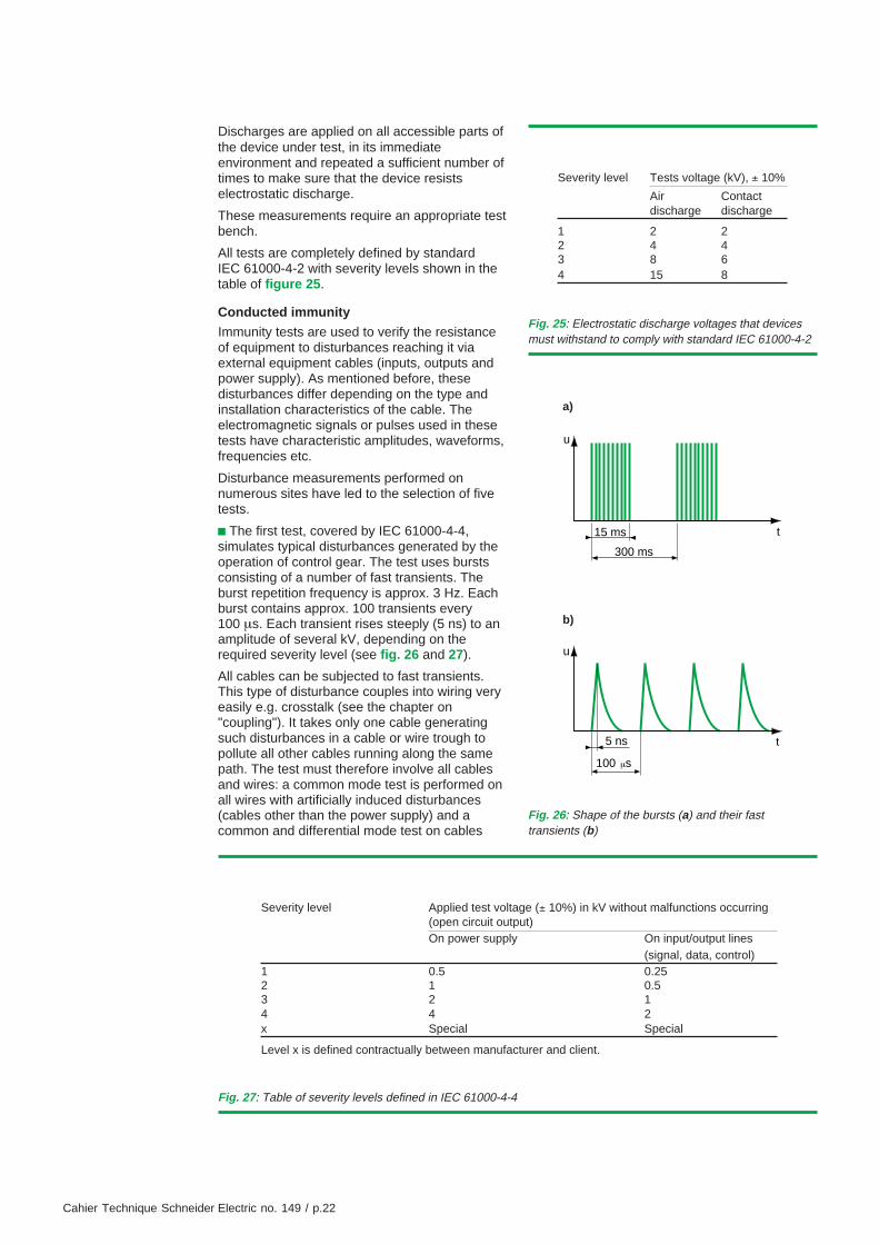
c The first test, covered by IEC 61000-4-4,simulates typical disturbances generated by theoperation of control gear. The test uses burstsconsisting of a number of fast transients. Theburst repetition frequency is approx. 3 Hz. Eachburst contains approx. 100 transients every100 µs. Each transient rises steeply (5 ns) to anamplitude of several kV, depending on therequired severity level (see fig. 26 and 27).
All cables can be subjected to fast transients.This type of disturbance couples into wiring veryeasily e.g. crosstalk (see the chapter on"coupling"). It takes only one cable generatingsuch disturbances in a cable or wire trough topollute all other cables running along the samepath. The test must therefore involve all cablesand wires: a common mode test is performed onall wires with artificially induced disturbances(cables other than the power supply) and acommon and differential mode test on cables
Fig. 27: Table of severity levels defined in IEC 61000-4-4
Severity level Applied test voltage (± 10%) in kV without malfunctions occurring(open circuit output)On power supply On input/output lines
(signal, data, control)1 0.5 0.252 1 0.53 2 14 4 2x Special Special
Level x is defined contractually between manufacturer and client.
Fig. 25: Electrostatic discharge voltages that devicesmust withstand to comply with standard IEC 61000-4-2
Severity level Tests voltage (kV), ± 10%
Air Contactdischarge discharge
1 2 22 4 43 8 64 15 8
Fig. 26: Shape of the bursts (a) and their fasttransients (b)
15 ms
300 ms
u
t
5 ns
100 sµ
u
t
a)
b)
Cahier Technique Schneider Electric no. 149 / p.23
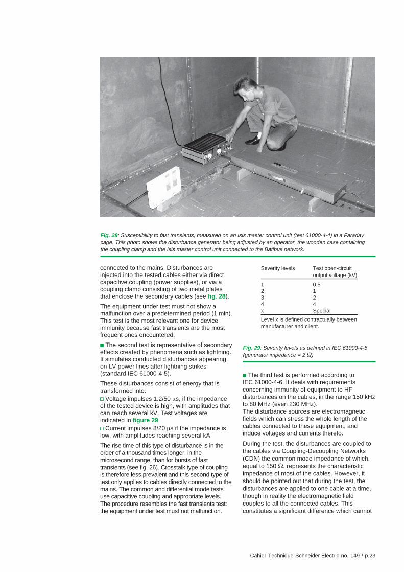
Fig. 28: Susceptibility to fast transients, measured on an Isis master control unit (test 61000-4-4) in a Faradaycage. This photo shows the disturbance generator being adjusted by an operator, the wooden case containingthe coupling clamp and the Isis master control unit connected to the Batibus network.
connected to the mains. Disturbances areinjected into the tested cables either via directcapacitive coupling (power supplies), or via acoupling clamp consisting of two metal platesthat enclose the secondary cables (see fig. 28).
The equipment under test must not show amalfunction over a predetermined period (1 min).This test is the most relevant one for deviceimmunity because fast transients are the mostfrequent ones encountered.
c The second test is representative of secondaryeffects created by phenomena such as lightning.It simulates conducted disturbances appearingon LV power lines after lightning strikes(standard IEC 61000-4-5).
These disturbances consist of energy that istransformed into:v Voltage impulses 1.2/50 µs, if the impedanceof the tested device is high, with amplitudes thatcan reach several kV. Test voltages areindicated in figure 29v Current impulses 8/20 µs if the impedance islow, with amplitudes reaching several kA
The rise time of this type of disturbance is in theorder of a thousand times longer, in themicrosecond range, than for bursts of fasttransients (see fig. 26). Crosstalk type of couplingis therefore less prevalent and this second type oftest only applies to cables directly connected to themains. The common and differential mode testsuse capacitive coupling and appropriate levels.The procedure resembles the fast transients test:the equipment under test must not malfunction.
Fig. 29: Severity levels as defined in IEC 61000-4-5(generator impedance = 2 Ω)
Severity levels Test open-circuitoutput voltage (kV)
1 0.52 13 24 4x Special
Level x is defined contractually betweenmanufacturer and client.
c The third test is performed according toIEC 61000-4-6. It deals with requirementsconcerning immunity of equipment to HFdisturbances on the cables, in the range 150 kHzto 80 MHz (even 230 MHz).The disturbance sources are electromagneticfields which can stress the whole length of thecables connected to these equipment, andinduce voltages and currents thereto.
During the test, the disturbances are coupled tothe cables via Coupling-Decoupling Networks(CDN) the common mode impedance of which,equal to 150 Ω, represents the characteristicimpedance of most of the cables. However, itshould be pointed out that during the test, thedisturbances are applied to one cable at a time,though in reality the electromagnetic fieldcouples to all the connected cables. Thisconstitutes a significant difference which cannot
Cahier Technique Schneider Electric no. 149 / p.24
be avoided. Indeed the test should be verycomplex and expensive if HF signals werecoupled to all the cables simultaneously.
If CDNs are not suitable, for example when thecurrent is too high, use coupling clamps.
The HF disturbances recommended by thestandard IEC 61000-4-6 have levels equal to 1,3 or 10 V. Their amplitude is modulated at 80%by a 1 kHz sine wave.
Prior to the test, the signal to be injected toobtain the right level is calibrated and stored,then applied to the cables connected to theequipment under test.
c The fourth test consists of creating fleetinginterruptions and/or voltage dips on the powersupply cables of the equipment under test.Standard IEC 61000-4-11 is the basic referencepublication.These disturbances are caused by faults in themains supply, the installation or by sudden majorchanges in the load. These random phenomenaare characterized both by their deviation fromthe rated voltage and their duration.The voltage dip levels are 30, 60 or 100%(breaking) of the rated voltage. Their durationvaries between 0.5 and 50 periods.
c The fifth test is conducted in accordance withstandard IEC 61000-4-12, which defines twotypes of waveform:
v Damped sine waves (also known as “ringwaves”) which appear in isolation on low voltagecables of public or private networks followingswitching operations
v Damped oscillating waves which appear in theform of bursts. These are generally found insubstations, power stations, or even largeindustrial installations, especially followingoperation of disconnectors accompanied by arcreignition.The transient voltages and currents resultingfrom these operations appear on the busbarsand are characterized by an oscillationfrequency that depends on their lengths andpropagation times. This frequency variesbetween 100 kHz and a few MHz for open highvoltage substations, and can reach as high asten MHz, or even more, for shielded high voltagesubstations.During the tests, the waves are coupled to thecables via coupling-decoupling networks.Depending on the injection method, theamplitude of the disturbances can vary between0.25 and 4 kV. “Table-top” devices are placed on
a post isolator, whereas “floor-standing” or“enclosed” devices are isolated from the groundplane by a distance of 0.1 m.
Immunity against radiated emission
The immunity tests against radiated emissionswere devised to ensure the satisfactoryoperation of equipment when exposed toelectromagnetic fields.
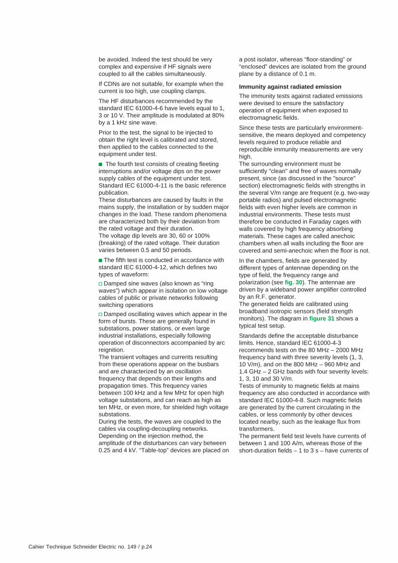
Since these tests are particularly environment-sensitive, the means deployed and competencylevels required to produce reliable andreproducible immunity measurements are veryhigh.The surrounding environment must besufficiently "clean" and free of waves normallypresent, since (as discussed in the "source"section) electromagnetic fields with strengths inthe several V/m range are frequent (e.g. two-wayportable radios) and pulsed electromagneticfields with even higher levels are common inindustrial environments. These tests musttherefore be conducted in Faraday cages withwalls covered by high frequency absorbingmaterials. These cages are called anechoicchambers when all walls including the floor arecovered and semi-anechoic when the floor is not.
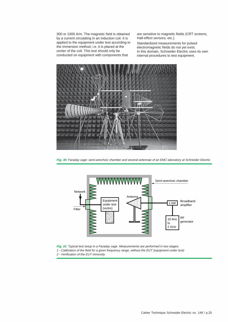
In the chambers, fields are generated bydifferent types of antennae depending on thetype of field, the frequency range andpolarization (see fig. 30). The antennae aredriven by a wideband power amplifier controlledby an R.F. generator.The generated fields are calibrated usingbroadband isotropic sensors (field strengthmonitors). The diagram in figure 31 shows atypical test setup.
Standards define the acceptable disturbancelimits. Hence, standard IEC 61000-4-3recommends tests on the 80 MHz – 2000 MHzfrequency band with three severity levels (1, 3,10 V/m), and on the 800 MHz – 960 MHz and1.4 GHz – 2 GHz bands with four severity levels:1, 3, 10 and 30 V/m.Tests of immunity to magnetic fields at mainsfrequency are also conducted in accordance withstandard IEC 61000-4-8. Such magnetic fieldsare generated by the current circulating in thecables, or less commonly by other deviceslocated nearby, such as the leakage flux fromtransformers.The permanent field test levels have currents ofbetween 1 and 100 A/m, whereas those of theshort-duration fields – 1 to 3 s – have currents of
Cahier Technique Schneider Electric no. 149 / p.25
300 or 1000 A/m. The magnetic field is obtainedby a current circulating in an induction coil. It isapplied to the equipment under test according tothe immersion method, i.e. it is placed at thecenter of the coil. This test should only beconducted on equipment with components that
Fig. 31: Typical test setup in a Faraday cage. Measurements are performed in two stages:1 - Calibration of the field for a given frequency range, without the EUT (equipment under test)2 - Verification of the EUT immunity
Equipmentunder test(victim)
Network
Filter
Broadbandamplifier
RFgenerator
Semi-anechoic chamber
Antenna
1 kW
10 kHzto2 GHz
Fig. 30: Faraday cage: semi-anechoic chamber and several antennae of an EMC laboratory at Schneider Electric
are sensitive to magnetic fields (CRT screens,Hall-effect sensors, etc.).
Standardized measurements for pulsedelectromagnetic fields do not yet exist.In this domain, Schneider Electric uses its owninternal procedures to test equipment.

Cahier Technique Schneider Electric no. 149 / p.26
Conducted emission
Conducted emission measurements quantify thedisturbances that the equipment under testre-injects into all cables connected to it.The disturbance strongly depends on the high-frequency characteristics of the load connectedto it since the equipment under test is thegenerator in this case (see fig. 32).
To obtain reproducible measurement results andespecially to avoid problems with thecharacteristic impedance of the network, theconducted emission measurements areperformed with the help of a Line ImpedanceStabilizing Network (LISN). A high-frequencyreceiver is connected to the network to measureemission levels at each frequency.
Fig. 33: Measurements of radio frequency emissions from a central data processing unit of a main switchboard.
X : NF EN 55022 A QC
Y : NF EN 55022 A AV
0.34
20
40
60
80
100
0.73 1.1 1.5 5.4 9.2 13 30
Sensor : LISNNo preamplifierReceiver : ESH3Detector : peakPass-band : 10 kHzSpacing : .0050 MHzMeasuring time : .1000 sImpulse limiter
Schneider Electric EMC laboratory
Mea
sure
d vo
ltage
(dB
µV
)
Frequency (MHz)
Fig. 32: Measurement configuration for conducted emissions. The EUT is the generator, the line impedancestabilizing network is the load.
Equipmentunder test(source)
Network
Filter
Measurementdevice
Line impedancestabilizing network
Semi-anechoic chamber

Cahier Technique Schneider Electric no. 149 / p.27
7. Conclusion
The use of electronics in a large number ofapplications, and especially in electrotechnicalequipment, has introduced a new and importantrequirement: electromagnetic compatibility (EMC).Trouble-free operation in disturbed environmentsand operation without producing disturbances areessential to product quality requirements. Toachieve both these goals, the complexphenomena involved in the sources, coupling andvictims must be well understood. A certainnumber of rules must be followed in the design,industrialization and manufacture of products.
The site and installation characteristics alsoplay an important role in electromagneticcompatibility.
This explains the importance of carefullyconsidering the location and layout of powercomponents, cable routing, shielding etc. rightfrom the initial design phase. Even if equipmentoffers satisfactory EMC, a well designedinstallation can extend the compatibility safetymargins.
Only measurements requiring a high level ofexpertise and sophisticated equipment canproduce valid results quantifying theelectromagnetic compatibility of equipment.
Compliance with standards therefore providesthe certainty that equipment will operatesatisfactorily in its electromagnetic environment.
The level of disturbances re-injected should notexceed the limits defined in the standards.These limits depend on the type of cable and theenvironment. The graph below (see fig. 33)shows the results of a measurement performedon a main LV switchboard and the levels definedin standard EN 55 022 for comparison.
Radiated emission
Radiated emission measurements quantify thelevel of disturbance emitted by a device in theform of electromagnetic waves.
Just as with radiated immunity tests, radiatedemission tests must be performed in theabsence of waves normally present such as CB,radio etc. and must not be modified byreflections from surrounding objects. These twoconditions are contradictory and this is thereason for the existence of two test methods.The first method consists of placing the EUT in afield free of obstacles within a given perimeter.The environment is uncontrolled.
The second method is implemented in a Faradaycage; the reflections from the walls aredeliberately attenuated by high frequencyabsorbing materials (see fig. 30). Theenvironment can be perfectly controlled.
The Schneider Electric laboratories use thesecond method. It offers a key advantage in thatmeasurements can be automated and alsoequipment handling is minimized, since emission
and immunity level measurements can beperformed at the same site with just few setupchanges.
As for conducted emissions, the emission levelsmust be less than the limits set by specificationsor standards.
Measuring pulsed fields
Standardized tests are performed to measureemission levels or test the immunity of devicesor systems to the most common types ofelectromagnetic disturbances encountered in anindustrial environment.
However, the environment for devices developedby Schneider Electric has certain characteristicsnot yet covered by standards.For example, specific EMC test procedures forequipment in medium voltage substations do notyet exist.
This is why Schneider Electric performs a seriesof measurements to better understand the typicaldisturbances that exist in the vicinity of theequipment it manufactures, especially near low,medium and very high voltage switchgear.
In a second phase, in-house tests using specialtest systems have been developed. They allowtesting of the electromagnetic compatibility ofdevices without having to revert to full-scale tests.These tests are easier to reproduce and lesscostly. They are performed early in the designwhich minimizes the costs of EMC protection.

Cahier Technique Schneider Electric no. 149 / p.28
Fig. 34: At equal lengths, the different impedances:a: cable in air (L ≈ 1 µH/m)b: cable placed on a metal surfacec: metal grid with electrical contact at each node (e.g. welded concrete reinforcing bars)d: metal surfacehave a per unit length impedance Z1 > Z2 > Z3 > Z4.
Z1Z2
Z4
c) d)
a) b)
Appendix 1: Impedance of a conductor at high frequencies
The level of EMC in equipment depends oncoupling between circuits. Coupling is directlyrelated to the impedance between circuits,especially at high frequencies. To improve EMC,these impedances must be determined and thenreduced.A few approximating formulae exist to determinethe high-frequency impedance of typicalconductors. These formulae are cumbersomeand their results meaningless if the exactposition of all involved elements is unknown. Butwho knows the exact position of a wire withrespect to the others in a cable trough? Theanswers to this and similar questions come fromexperience together with basic knowledge of thetheory of electrical phenomena.
First of all it is important to keep in mind that theimpedance of a conductor is mainly a function ofits inductance and becomes preponderantstarting at a few kilohertz for a standard wire.For a wire assumed to be infinitely long, theinductance per unit length increaseslogarithmically with the diameter, therefore veryslowly: for wires that do not exceed 1/4 of the
disturbance wavelength, an inductance ofone µH/m can be used irrespective of thediameter (see fig. 34).
This value is much lower when the wire iscorrectly run against a conductive plane.It becomes a function of the distance betweenthe wire and the plane and the inductance caneasily be decreased by 10 dB. At very highfrequencies the wire must be considered as atransmission line with a characteristic impedanceof around one hundred ohms.In this light, a common inductance of several µHcan easily be created, for example, with a fewmeters of green-yellow (grounding) wire. Thistranslates into a few ohms at 1 MHz and a fewhundred ohms at 100 MHz.
Conclusion: A conducting metal platerepresents the electrical interconnect offering thelowest impedance, independent of thickness aslong as it is greater than the skin depth (415 µmat 10 kHz for copper). A copper plate displays aninductance of 0.6 nH (at 10 kHz) and animpedance of 37 µΩ per square (the impedanceremains the same irrespective of the surface).
Z3

Cahier Technique Schneider Electric no. 149 / p.29
Insulator (PVC)
Jacket (two steel bands)
Cushion (paper)
Metal screen(copper)
Conductive ribbon
Core (copper wire)
Insulator (PVC)
Filler
Insulator (PVC)
Jacket (two steel bands)
Internal insulation(PVC)
Metal screen(aluminum)
Insulator (PVC)
Core (copper wire)
Appendix 2: The different parts of a cable
The technical terms used to describe differentparts of a cable can have slightly differentmeanings depending on the cable’s field ofapplication (power transmission, telephone, dataor control and monitoring) (see fig. 35).
The IEC definitions are in italics.
Jacket: The jacket’s most important role is toprotect the cable from mechanical damage. Thatis why it usually contains two helically strandedsoft steel bands.For data transmission cables, it also serves asan electrostatic and more often anelectromagnetic shield.
Shield: Same as a screen; i.e. device designedto reduce the intensity of electromagneticradiation penetrating into a certain region.A jacket or screen of a cable, whether for poweror data transmission, can form a shield.
Screen: A device used to reduce the penetrationof a field into an assigned region.
It has multiple functions:
c Creation of an equipotential surface around theinsulator
c Protection against the effects of external andinternal electrostatic fields
c Draining the capacitive current as well as earthleakage fault currents (zero sequence short-circuits)
c Protection of life and property in the event of apuncture. For this reason, it is generally made ofmetal and is continuous (lead tubing, braidedwire, helically wound bands).
For cables carrying data, the screen, more oftencalled a shield, consists of copper or aluminiumwire bands or braids, wrapped around to form ashield against electrostatic or electromagneticfields.It can be an overall shield, for all conductors inthe cable, when the disturbances are external tothe cable.It can also be partial, for a limited number ofconductors, to protect against disturbancesemitted by the other conductors in the cable.
Insulator: The insulator renders the cable waterand/or air tight.
Fig. 35
Telephone cable Medium voltage power transmission cable

Cahier Technique Schneider Electric no. 149 / p.30
Appendix 3: Tests performed at Schneider ElectricEMC laboratories
The EMC laboratories of Schneider Electric havethe necessary equipment and expertise toperform tests in accordance with a large numberof standards or specifications.The laboratory clients, whether internal orexternal to the Company, can benefit from theexperience of the laboratory staff in finding the
right standards applicable to their product, andalso to determine the functional acceptabilitycriteria according to standards relative to theproduct, if they exist, otherwise according tofunctional requirements relative to safety,continuity of service, comfort, etc.
Standardized tests
Giving a complete list of all the test standardswould be tedious and inevitably incomplete dueto the rapid evolution in the publication ofproduct test standards. We therefore indicatehereafter the main reference standardsregarding the performance of EMC tests.Local EMC standards exist in many countries.The EEC countries have generally issued localstandards equivalent to the following IECstandards.
Immunityc IEC 61000-4-2 (= EN 61000-4-2)Electromagnetic compatibility (EMC)Part 4-2: Testing and measurement techniques -Electrostatic discharge immunity test
c IEC 61000-4-3 (= EN 61000-4-3)Electromagnetic compatibility (EMC)Part 4-3: Testing and measurement techniques -Radiated, radio-frequency, electromagnetic fieldimmunity test
c IEC 61000-4-4 (= EN 61000-4-4)Electromagnetic compatibility (EMC)Part 4-4: Testing and measurement techniques -Electrical fast transient/burst immunity test
c IEC 61000-4-5 (= EN 61000-4-5)Electromagnetic compatibility (EMC)Part 4-5: Testing and measurement techniques -Surge immunity test
c IEC 61000-4-6 (= EN 61000-4-6)Electromagnetic compatibility (EMC)Part 4-6: Testing and measurement techniques -Immunity to conducted disturbances, induced byradio-frequency fields
c IEC 61000-4-8 (= EN 61000-4-8)Electromagnetic compatibility (EMC)Part 4-8: Testing and measurement techniques -Power frequency magnetic field immunity test
c IEC 61000-4-11 (= EN 61000-4-11)Electromagnetic compatibility (EMC)Part 4-11: Testing and measurement techniques -Voltage dips, short interruptions and voltagevariations immunity tests
c IEC 61000-4-12 (=EN 61000-4-12)Electromagnetic compatibility (EMC)Part 4-12: Testing and measurement techniques -Oscillatory waves immunity test
c IEC 61000-6-1 (=EN 61000-6-1)Electromagnetic compatibility (EMC)Part 6-1: Generic standards -Immunity for residential, commercial and light-industrial environments
c IEC 61000-6-2 (=EN 61000-6-2)Electromagnetic compatibility (EMC)Part 6-2: Generic standards -Immunity for industrial environments
Emissionc CISPR 11Industrial, scientific and medical (ISM) radio-frequency equipment - Electromagneticdisturbance characteristics - Limits and methodsof measurement
c CISPR 14Limits and methods of measurement of radiodisturbance characteristics of electrical motor-operated and thermal appliances for householdand similar purposes, electric tools and electricapparatus
c CISPR 22Information technology equipment - Radiodisturbance characteristics - Limits and methodsof measurement
c EN 55011Limits and methods of measurement of radiodisturbance characteristics of industrial, scientificand medical (ISM) radio frequency equipment
c EN 55014Limits and methods of measurement of radiodisturbance characteristics of householdappliances, electric tools and similar apparatus(conducted emission part)
c EN 55 022Limits and methods of measurement of radiointerference characteristics of informationtechnology equipment

Cahier Technique Schneider Electric no. 149 / p.31
c IEC 61000-6-3Electromagnetic compatibility (EMC)Part 6: Generic standardsSection 3: Emission standard for residential,commercial and light-industrial environmentsc IEC 61000-6-4Electromagnetic compatibility (EMC)Part 6: Generic standardsSection 4: Emission standard for industrialenvironmentsc EN 50081-1Electromagnetic compatibility (EMC)Generic emission standardPart 1 - Residential, commercial and light industry
c EN 50081-2Electromagnetic compatibility (EMC)Generic emission standardPart 2 - Industrial environment.
Specific standardsc Centres de télécommunicationsI 12-10, 1993published by Comité des Spécifications desEquipements (CSE) France Télécom.Environnement électromagnétique deséquipements des centres.(partie immunité aux perturbations rayonnées etpartie perturbations rayonnées et conduites)
c MIL STD 461/462Electromagnetic emission and susceptibilityrequirements for the control of electromagneticinterference
Non-standardized tests
Within the limits of available expertise andfacilities, the laboratory can perform testscomplying with other standards.
Cahier Technique Schneider Electric no. 149 / p.32
Appendix 4: Bibliography
Standardsc IEC 60364Low voltage electrical installationsc IEC 61000-2Electromagnetic compatibility (EMC)Part 2: EnvironmentSection 1: Description of the environment -Electromagnetic environment for conducteddisturbancesSection 2: Compatibility level for low-frequencyconducted disturbances and signalling in publicpower supply systemsPart 4: Testing and measurement techniquesPart 6: Generic standardsc EN 55011Industrial, scientific and medical (ISM) radio-frequency equipment. Electromagneticdisturbance characteristics. Limits and methodsof measurementc EN 55022Limits and methods of measurement of radiointerference characteristics of informationtechnology equipment
Schneider Electric Cahiers Techniquesc Electrical disturbances in LVCahier technique no. 141R. CALVAS
c Behaviour of the SF6-MV circuit breakersFluarc for switching motor starting currentsCahier technique no. 143J. HENNEBERT and D. GIBBS
c Cohabitation of high and low currentsCahier technique no. 187R. CALVAS and J. DELABALLE
Other publicationsc Compatibilité électromagnétique - bruits etperturbations radioélectriques -P. DEGAUQUE and J. HAMELINDunod éditeur
c Compatibilité électromagnétiqueM. IANOVICI and J.-J. MORFPresses Polytechniques Romandes
c La compatibilité électromagnétiqueA. KOUYOUMDJIAN, with R. CALVAS andJ. DELABALLEInstitut Schneider FormationFebruary 1996, ref. MD1CEM1F
c Les harmoniques et les installationsélectriquesA. KOUYOUMDJIANInstitut Schneider FormationApril 1998, ref. MD1HRM1F
c RGE no. 10 consacré à la compatibilitéélectromagnétiqueNovember 1986


© 2
001
Sch
neid
erE
lect
ric
12-0163498
Schneider Electric Direction Scientifique et Technique,Service Communication TechniqueF-38050 Grenoble cedex 9Télécopie : 33 (0)4 76 57 98 60E-mail : [email protected]
DTP: Schneider ElectriEdition: Schneider Electric
- 20 € -