Cahier technique n 181studiecd.dk/cahiers_techniques/Directional_protection... · 2020-01-29 ·...
28
.......................................................................... Collection Technique Cahier technique n° 181 Directional protection equipment P. Bertrand ■ Merlin Gerin ■ Modicon ■ Square D ■ Telemecanique
Transcript of Cahier technique n 181studiecd.dk/cahiers_techniques/Directional_protection... · 2020-01-29 ·...
..........................................................................Collection Technique
Cahier technique n° 181
Directional protection equipment
P. Bertrand
■ Merlin Gerin ■ Modicon ■ Square D ■ Telemecanique
Cahiers Techniques are a collection of documents intended for engineersand technicians people in the industry who are looking for information ingreater depth in order to complement that given in display productcatalogues.
These Cahiers Techniques go beyond this stage and constitute praticaltraining tools.They contain data allowing to design and implement electrical equipement,industrial electronics and electrical transmission and distribution.Each Cahier Technique provides an in-depth study of a precise subject inthe fields of electrical networks, protection devices, monitoring and controland industrial automation systems.
The latest publications can be downloaded on Internet from theSchneider server.code: http://www.schneiderelectric.comsection: mastering electrical power
Please contact your Schneider representative if you want either a CahierTechnique or the list of available titles.
The « Cahiers Techniques » collection is part of the Groupe Schneider’s« Collection Technique ».
ForewordThe author disclaims all responsibility further to incorrect use of informationor diagrams reproduced in this document, and cannot be held responsiblefor any errors or oversights, or for the consequences of using informationand diagrams contained in this document.
Reproduction of all or part of a Cahier Technique is authorised with theprior consent of the Scientific and Technical Division. The statement« Extracted from Schneider Cahier Technique no..... (please specify) » iscompulsory.

Pierre BERTRAND
An INPG Engineer (Institute National Polytechnique de Grenoble)graduating in 1979, he joined Merlin Gerin in 1983 and was involved inresearch on the operation and disturbances on electrical networks upto 1986. He then joined the Protection and Control activity in which heheld various marketing and technical positions. He is currentlyleading an electrotechnical excellence group within this activity'stechnical department.
n° 181Directional protectionequipment
E/CT 181 (e) first issued, march 1998
Cahier Technique Schneider n° 181/ p.2
Lexicon
ANSI code: digital code assigned to a protectionfunction, defined in the ANSI C37-2 standard.Characteristic angle (in a directionalprotection equipment): angle between thepolarisation quantity of relay and the normal tothe tripping zone boundary line (see fig. 10 ).Differential protection: zone protection whichdetects a fault by measuring and comparingcurrents at the input and output of the protectedzone or equipment.Directional protection: protection equipmentcapable of detecting a fault upstream ordownstream (in a given direction) of its position.Earth fault (e/f) protection: protection in whichthe residual variable (current and/or voltage) ismonitored to detect phase-to-earth fault.Phase protection: protection in which the phasecurrent and/or voltage variables are monitored.Phase-to phase-voltage (annotation):U32 = V2-V3.
Polarisation quantity (in a directionalprotection equipment): the variable used asthe phase reference.Protection plan: the protection equipmentincorporated in an electrical network in order todetect faults and to disconnect the smallestpossible part of the faulty network.(protection) Relay: equipment used to monitorone or more electrical variable (current orvoltage), generally to detect a fault and to controlthe opening of a circuit breaker.Relay connection angle (in a phasedirectional protection equipment): the anglebetween the chosen polarisation variable and thephase to earth voltage of the monitored phasequalifies the polarisation variable.Residual: (current or voltage in a three phasenetwork) : the vectorial sum of the values of allthree phases.Zero sequence (current or voltage, in a threephase network): 1/3 of the residual variable.
Cahier Technique Schneider n° 181 / p.3
Directional protection equipment
This "Cahier Technique" aims to give the reader a better understanding ofso called "directional" protection: a very useful technology for HV networksand machines.Advances in digital technology and the integration of logical selectivity, hasenabled it to make great progress in terms of reliability, simplicity ofincorporation and even costs.
Its use allows to implement network configuration and selectivity systemimproving the dependability of power supplies.After reviewing their operating principle, the author goes on to present theirmany applications and gives some useful information on theirincorporation.
Contents
1. Introduction 1.1 The role of directional protection equipment p. 4
1.2 Applications p. 4
1.3 The codes and symbols of the various relay types p. 5
2. Description of directional relays 2.1 Earth fault directional protection p. 6
2.2 Phase directional protection p. 9
2.3 Power protection p. 11
3. Applications of directional protection 3.1 Protection of radial networks p. 12
3.2 Protection of closed rings p. 16
3.3 Protection of alternators p. 19
4. Use 4.1 Sizing of current and voltage transformers p. 21
4.2 Selection between two or three phase protection p. 22
4.3 Protecting parallel connected transformers p. 22
5. Developments and outlook 5.1 Developments in protection equipment technology p. 23
5.2 Developments in sensors p. 24
5.3 In conclusion p. 24
equipment
Cahier Technique Schneider n° 181 / p.4
1 Introduction
1.1 The role of directional protection equipment
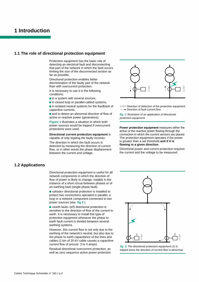
Protection equipment has the basic role ofdetecting an electrical fault and disconnectingthat part of the network in which the fault occurslimiting the size of the disconnected section asfar as possible.
Directional protection enables betterdiscrimination of the faulty part of the networkthan with overcurrent protection.
It is necessary to use it in the followingconditions:c in a system with several sources,c in closed loop or parallel-cabled systems,c in isolated neutral systems for the feedback ofcapacitive currents,c and to detect an abnormal direction of flow ofactive or reactive power (generators).
Figure 1 illustrates a situation in which bothpower sources would be tripped if overcurrentprotections were used.
Directional current protection equipment iscapable of only tripping the faulty incomer.
The direction in which the fault occurs isdetected by measuring the direction of currentflow, or in other words the phase displacementbetween the current and voltage.
fig. 1 : lIlustration of an application of directionalprotection equipment.
Direction of detection of the protection equipmentDirection of fault current flow
1 2
fig. 2 : The directional protection equipment (1) istripped since the direction of current flow is abnormal.
Power protection equipment measures either theactive or the reactive power flowing through theconnection in which the current sensors are placed.The protection equipment operates if the poweris greater than a set threshold and if it isflowing in a given direction .Directional power and current protection requiresthe current and the voltage to be measured.
1.2 Applications
Directional protection equipment is useful for allnetwork components in which the direction offlow of power is likely to change, notably in theinstance of a short circuit between phases or ofan earthing fault (single phase fault).
c «phase» directional protection is installed toprotect two connections operated in parallel, aloop or a network component connected to twopower sources (see fig 2 ).
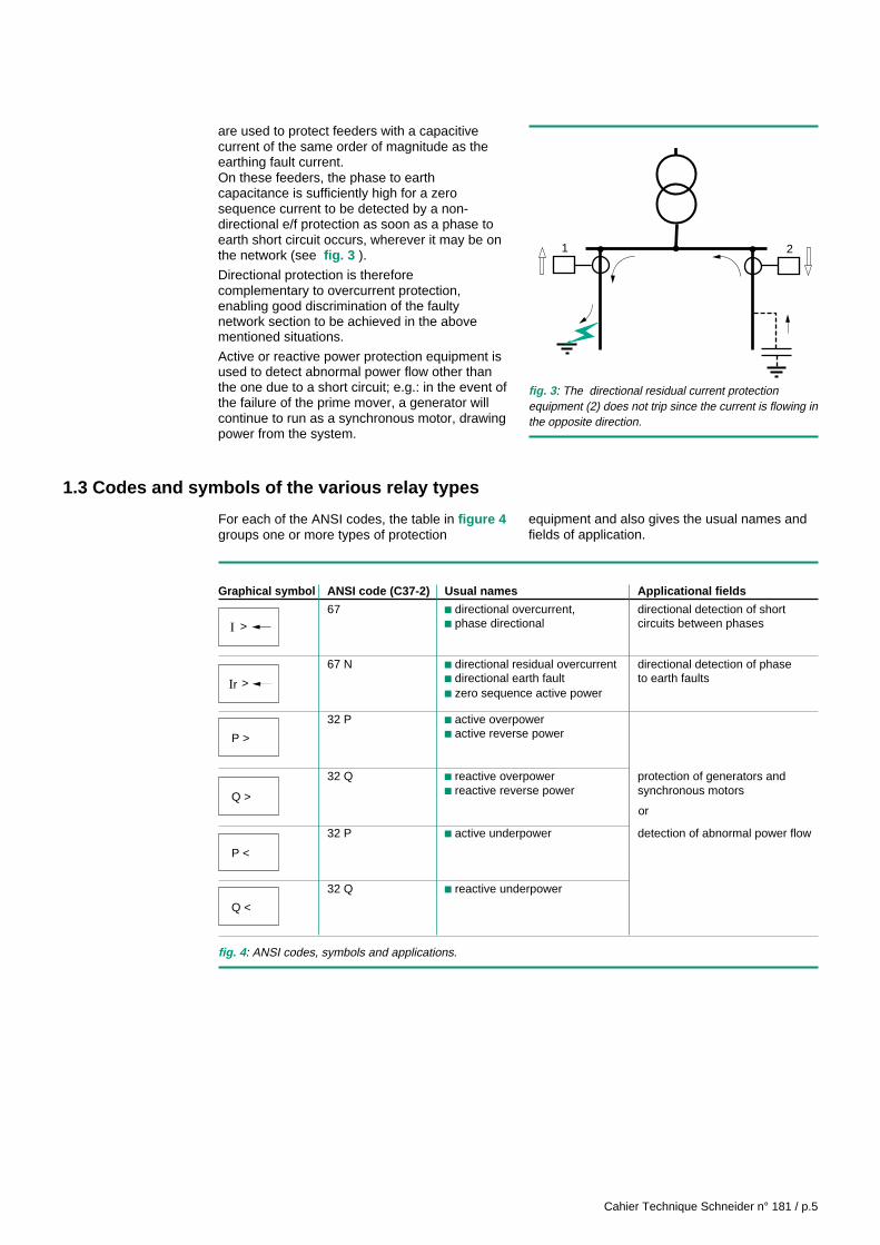
c «earth fault» (e/f) directional protection issensitive to the direction of flow of the current toearth. It is necessary to install this type ofprotection equipment whenever the phase toearth fault current is divided between severalearthing systems.
However, this current flow is not only due to theearthing of the network's neutral, but also due tothe phase to earth capacitance of the lines andcables (1 km of 20 kV cable causes a capacitivecurrent flow of around 3 to 4 amps).
Residual directional overcurrent protection, aswell as zero sequence active power protection
Cahier Technique Schneider n° 181 / p.5
are used to protect feeders with a capacitivecurrent of the same order of magnitude as theearthing fault current.On these feeders, the phase to earthcapacitance is sufficiently high for a zerosequence current to be detected by a non-directional e/f protection as soon as a phase toearth short circuit occurs, wherever it may be onthe network (see fig. 3 ).
Directional protection is thereforecomplementary to overcurrent protection,enabling good discrimination of the faultynetwork section to be achieved in the abovementioned situations.
Active or reactive power protection equipment isused to detect abnormal power flow other thanthe one due to a short circuit; e.g.: in the event ofthe failure of the prime mover, a generator willcontinue to run as a synchronous motor, drawingpower from the system.
1.3 Codes and symbols of the various relay types
For each of the ANSI codes, the table in figure 4groups one or more types of protection
1 2
fig. 3 : The directional residual current protectionequipment (2) does not trip since the current is flowing inthe opposite direction.
fig. 4 : ANSI codes, symbols and applications.
equipment and also gives the usual names andfields of application.
Graphical symbol ANSI code (C37-2) Usual names Applicational fields
67 c directional overcurrent, directional detection of shortc phase directional circuits between phases
67 N c directional residual overcurrent directional detection of phasec directional earth fault to earth faultsc zero sequence active power
32 P c active overpowerc active reverse power
32 Q c reactive overpower protection of generators andc reactive reverse power synchronous motors
32 P c active underpower detection of abnormal power flow
32 Q c reactive underpower
I >
Ir >
Q >
P <
Q <
P >
or

Cahier Technique Schneider n° 181 / p.6
2 Description of directional relays
In order to measure a value of power or tolocalise a fault upstream or downstream of thepoint at which the current is measured, thephase displacement of the current must bedetermined relative to a reference variable: the
phase to phase voltage for directional phaseprotection and the residual voltage for directionalearthing protection.
This reference variable is called the polarisationquantity.
2.1 Earth fault directional protection
Input variablesIn earth fault directional protection, the residualcurrent is measured and the residual voltageis most often used as the polarisation quantity.The latter should not be confused with thezero sequence voltage.Recall that in any three phase systemF1, F2, F3, symmetrical component
fig. 5 : Measuring the residual current using 3 CT's.
I1 I2 I3
ir = i1 + i2 + i3
i2
i1
i3
I1 I2 I3
ir
fig. 6 : Measuring the residual current using 3 CT's.
theory defines the zero sequence variable Fhas:
Fh F F F→ → → →
= + +
.13
1 2 3
The residual variable:
Fr F F F = + +→ → →1 2 3 is three times greater than
the zero sequence variable.c The residual current is either measured bythree current transformers, one per phase, or bya coil (ring CT) around the three phases.
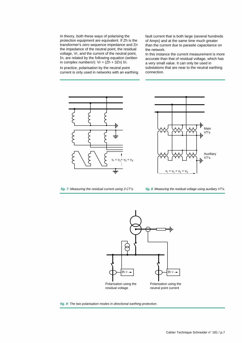
v The use of three current transformers (seefig. 5 ) has certain advantages:- CT's are generally dependable,- it is possible to measure high currents.But it also has certain disadvantages:- saturation of the CT's in the instance of a shortcircuit or when a transformer is switched onproduces a false residual current- in practice, the threshold cannot be set tounder 10% of the CT's rated current.v Measuring using a ring CT (see fig. 6 )- has the advantage of being very sensitive,- and the disadvantage of the coil (low voltageinsulated) being installed around a non-cladcable to insulate it.c Residual voltage is measured by three voltagetransformers (VT); often VT's with two secondarywindings are used (see fig. 7 ): one is starconnected and enables both phase to neutraland phase to phase voltages to be measured;the other is open delta connected enabling theresidual voltage to be measured.If the main VT's only have one secondarywinding are star connected, and grounded, a setof auxiliary VT's can be used to measure theresidual voltage (see fig 8 ). This situation isoften encountered when the protection plan forexisting installations is upgraded.It should be noted that certain protectionequipment does not require auxiliary VT's, theequipment itself providing the residual voltagevalue from the three phase to earth voltages.ccccc The residual voltage is most often used as thepolarisation variable for an earth fault directionalrelay; however, it may also be taken as thecurrent in the installation's neutral earthingarrangement (see fig. 9 ).
Cahier Technique Schneider n° 181 / p.7
vr = v1+ v2 + v3
fig. 7 : Measuring the residual current using 3 CT's.
In theory, both these ways of polarising theprotection equipment are equivalent. If Zh is thetransformer's zero sequence impedance and Znthe impedance of the neutral point, the residualvoltage, Vr, and the current of the neutral point,In, are related by the following equation (writtenin complex numbers!): Vr = (Zh + 3Zn) In.
In practice, polarisation by the neutral pointcurrent is only used in networks with an earthing
MainVT's
AuxiliaryVT's
vr = v1 + v2 + v3
fig. 8 : Measuring the residual voltage using auxiliary VT's.
Ih > Ih >
Polarisation using the residual voltage
Polarisation using the neutral point current
fig. 9 : The two polarisation modes in directional earthing protection.
fault current that is both large (several hundredsof Amps) and at the same time much greaterthan the current due to parasite capacitance onthe network.In this instance the current measurement is moreaccurate than that of residual voltage, which hasa very small value. It can only be used insubstations that are near to the neutral earthingconnection.
Cahier Technique Schneider n° 181 / p.8
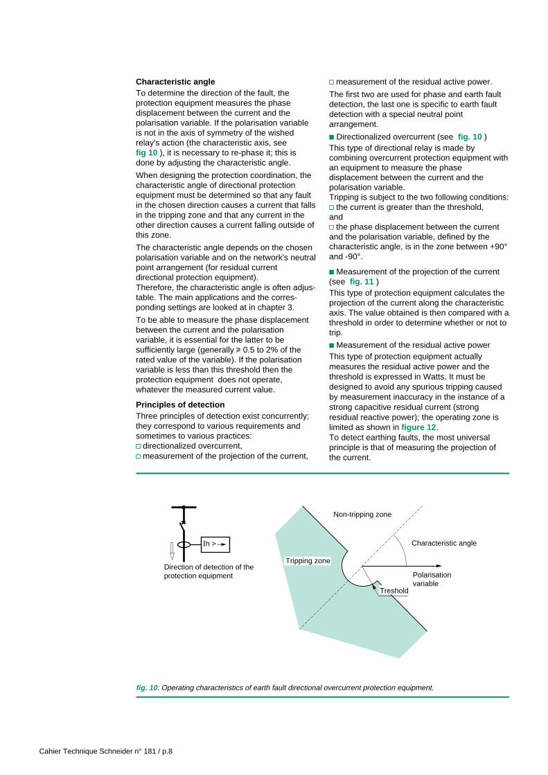
Characteristic angleTo determine the direction of the fault, theprotection equipment measures the phasedisplacement between the current and thepolarisation variable. If the polarisation variableis not in the axis of symmetry of the wishedrelay's action (the characteristic axis, seefig 10 ), it is necessary to re-phase it; this isdone by adjusting the characteristic angle.
When designing the protection coordination, thecharacteristic angle of directional protectionequipment must be determined so that any faultin the chosen direction causes a current that fallsin the tripping zone and that any current in theother direction causes a current falling outside ofthis zone.
The characteristic angle depends on the chosenpolarisation variable and on the network's neutralpoint arrangement (for residual currentdirectional protection equipment).Therefore, the characteristic angle is often adjus-table. The main applications and the corres-ponding settings are looked at in chapter 3.
To be able to measure the phase displacementbetween the current and the polarisationvariable, it is essential for the latter to besufficiently large (generally u 0.5 to 2% of therated value of the variable). If the polarisationvariable is less than this threshold then theprotection equipment does not operate,whatever the measured current value.
Principles of detectionThree principles of detection exist concurrently;they correspond to various requirements andsometimes to various practices:v directionalized overcurrent,v measurement of the projection of the current,
v measurement of the residual active power.
The first two are used for phase and earth faultdetection, the last one is specific to earth faultdetection with a special neutral pointarrangement.
c Directionalized overcurrent (see fig. 10 )This type of directional relay is made bycombining overcurrent protection equipment withan equipment to measure the phasedisplacement between the current and thepolarisation variable.Tripping is subject to the two following conditions:v the current is greater than the threshold,andv the phase displacement between the currentand the polarisation variable, defined by thecharacteristic angle, is in the zone between +90°and -90°.
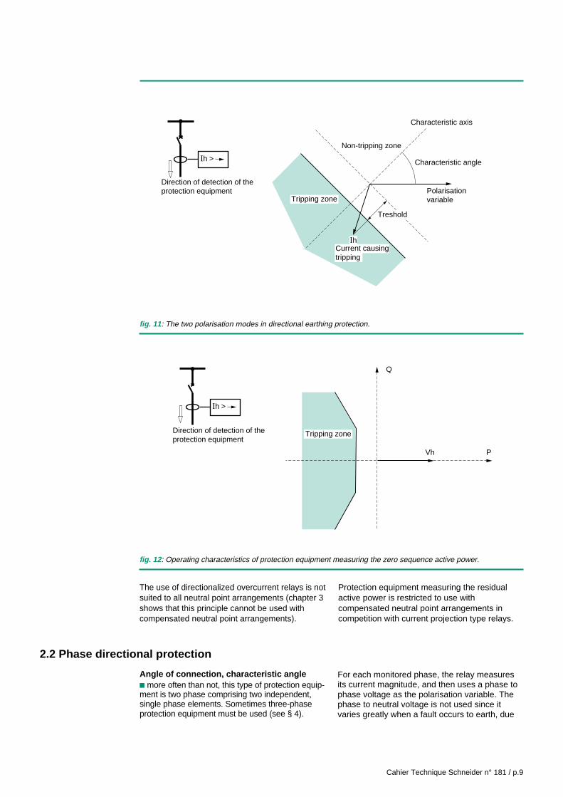
c Measurement of the projection of the current(see fig. 11 )This type of protection equipment calculates theprojection of the current along the characteristicaxis. The value obtained is then compared with athreshold in order to determine whether or not totrip.
c Measurement of the residual active powerThis type of protection equipment actuallymeasures the residual active power and thethreshold is expressed in Watts. It must bedesigned to avoid any spurious tripping causedby measurement inaccuracy in the instance of astrong capacitive residual current (strongresidual reactive power); the operating zone islimited as shown in figure 12 .To detect earthing faults, the most universalprinciple is that of measuring the projection ofthe current.
Treshold
Ih >
Polarisationvariable
Tripping zone
Characteristic angle
Non-tripping zone
Direction of detection of theprotection equipment
fig. 10 : Operating characteristics of earth fault directional overcurrent protection equipment.
Cahier Technique Schneider n° 181 / p.9
fig. 11 : The two polarisation modes in directional earthing protection.
Vh P
Q
Ih >
Tripping zoneDirection of detection of theprotection equipment
fig. 12 : Operating characteristics of protection equipment measuring the zero sequence active power.
The use of directionalized overcurrent relays is notsuited to all neutral point arrangements (chapter 3shows that this principle cannot be used withcompensated neutral point arrangements).
Protection equipment measuring the residualactive power is restricted to use withcompensated neutral point arrangements incompetition with current projection type relays.
Ih
PolarisationvariableTripping zone
Characteristic axis
Characteristic angle
Non-tripping zone
Current causingtripping
Ih >
Treshold
Direction of detection of theprotection equipment
2.2 Phase directional protection
Angle of connection, characteristic anglec more often than not, this type of protection equip-ment is two phase comprising two independent,single phase elements. Sometimes three-phaseprotection equipment must be used (see § 4).
For each monitored phase, the relay measuresits current magnitude, and then uses a phase tophase voltage as the polarisation variable. Thephase to neutral voltage is not used since itvaries greatly when a fault occurs to earth, due
Cahier Technique Schneider n° 181 / p.10
to the displacement effect of the neutral point(residual voltage).
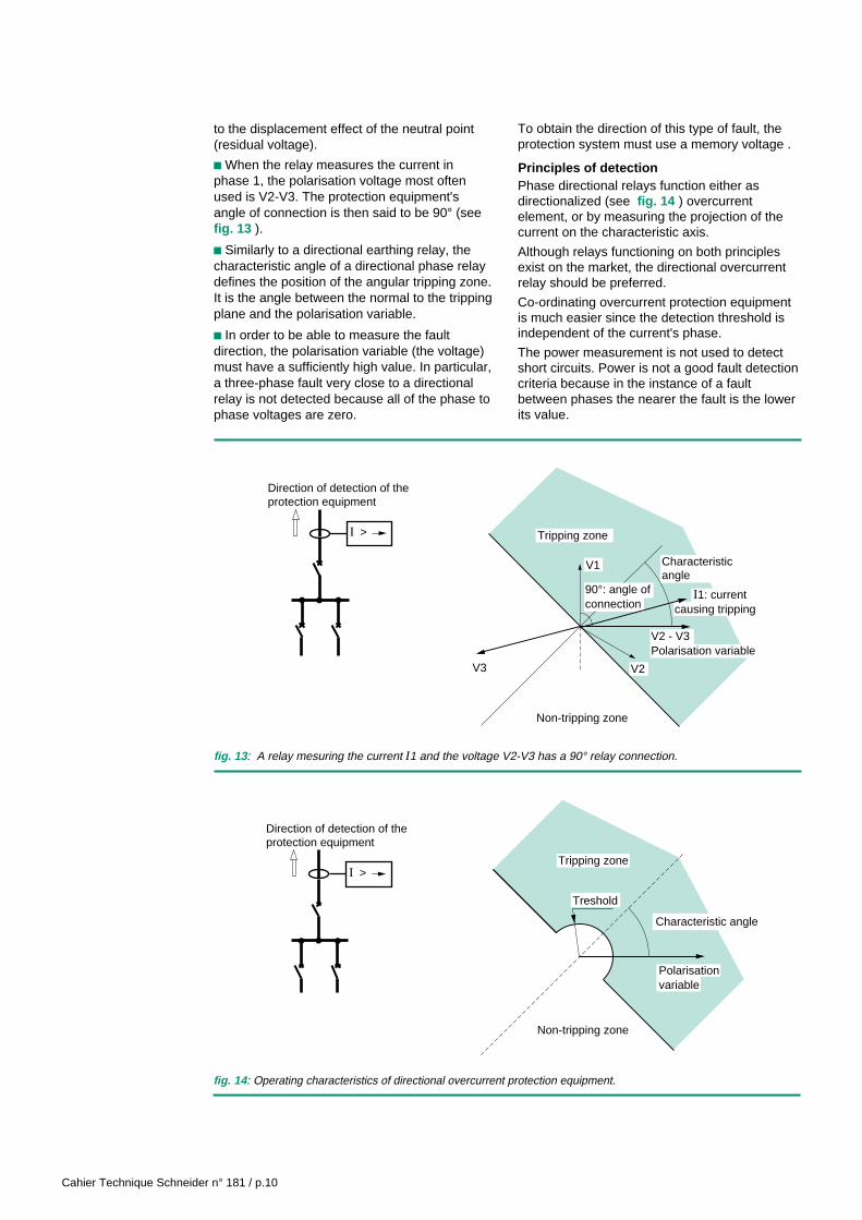
c When the relay measures the current inphase 1, the polarisation voltage most oftenused is V2-V3. The protection equipment'sangle of connection is then said to be 90° (seefig. 13 ).
c Similarly to a directional earthing relay, thecharacteristic angle of a directional phase relaydefines the position of the angular tripping zone.It is the angle between the normal to the trippingplane and the polarisation variable.
c In order to be able to measure the faultdirection, the polarisation variable (the voltage)must have a sufficiently high value. In particular,a three-phase fault very close to a directionalrelay is not detected because all of the phase tophase voltages are zero.
To obtain the direction of this type of fault, theprotection system must use a memory voltage .
Principles of detectionPhase directional relays function either asdirectionalized (see fig. 14 ) overcurrentelement, or by measuring the projection of thecurrent on the characteristic axis.
Although relays functioning on both principlesexist on the market, the directional overcurrentrelay should be preferred.
Co-ordinating overcurrent protection equipmentis much easier since the detection threshold isindependent of the current's phase.
The power measurement is not used to detectshort circuits. Power is not a good fault detectioncriteria because in the instance of a faultbetween phases the nearer the fault is the lowerits value.
fig. 13 : A relay mesuring the current I1 and the voltage V2-V3 has a 90° relay connection.
V2 - V3Polarisation variable
90°: angle ofconnection
V3 V2
V1
I > Tripping zone
Characteristicangle
Non-tripping zone
I1: currentcausing tripping
Direction of detection of theprotection equipment
I >
Non-tripping zone
Treshold
Characteristic angle
Tripping zone
Polarisationvariable
Direction of detection of theprotection equipment
fig. 14 : Operating characteristics of directional overcurrent protection equipment.

Cahier Technique Schneider n° 181 / p.11
2.3 Power relays
This type of protection equipment often uses adual wattmeter method to measure the activepower, with a variant, that we will call the dualVARmeter method, which measures the reactivepower.
Recall that this method enables the power to bemeasured using two current and two phase tophase voltage measurements (see fig. 15 ). Itapplies to a three-phase network, whetherbalanced or not, as long as there is no zerosequence current in the circuit.
This method is particularly unsuited to lowvoltage 4-wire networks, or in other words anetwork in which the neutral is distributed,supplying single phase loads connected betweenthe phase and the neutral.
The active power is given by:
P = I1 U31 cos (I1, U31) + I2 U32 cos (I2, U32).
Similarly, the reactive power is given by:Q = I1 U31 sin (I1, U31) + I2 U32 sin (I2, U32).
The measured power is therefore an algebraicvariable, and the direction of flow is indicated byits sign (+/-). Power protection equipment istherefore naturally directional. Certain relays use
three single phase measurements to determinethe power.
These relays will therefore be usable with 4-wirenetworks ; they do however have thedisadvantage of requiring 3 VT's and 3 CT's tobe installed.
I1 I2 I3
X
X
P+
fig. 15 : Layout diagram for measuring power.
Cahier Technique Schneider n° 181 / p.12
3 Applications of directional protection equipment
3.1 Protection of radial networks
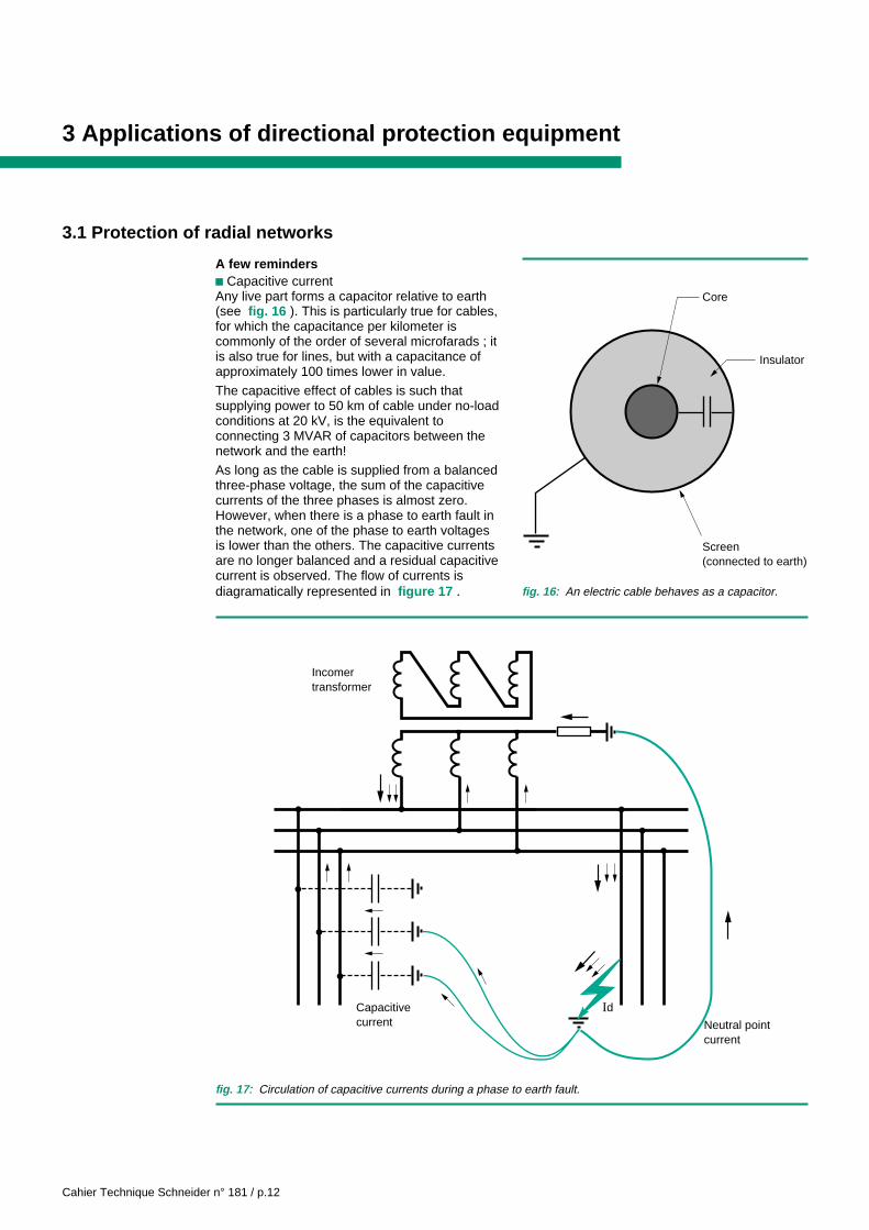
A few remindersc Capacitive currentAny live part forms a capacitor relative to earth(see fig. 16 ). This is particularly true for cables,for which the capacitance per kilometer iscommonly of the order of several microfarads ; itis also true for lines, but with a capacitance ofapproximately 100 times lower in value.
The capacitive effect of cables is such thatsupplying power to 50 km of cable under no-loadconditions at 20 kV, is the equivalent toconnecting 3 MVAR of capacitors between thenetwork and the earth!
As long as the cable is supplied from a balancedthree-phase voltage, the sum of the capacitivecurrents of the three phases is almost zero.However, when there is a phase to earth fault inthe network, one of the phase to earth voltagesis lower than the others. The capacitive currentsare no longer balanced and a residual capacitivecurrent is observed. The flow of currents isdiagramatically represented in figure 17 . fig. 16 : An electric cable behaves as a capacitor.
Screen(connected to earth)
Core
Insulator
Incomertransformer
IdNeutral pointcurrent
Capacitivecurrent
fig. 17 : Circulation of capacitive currents during a phase to earth fault.

Cahier Technique Schneider n° 181 / p.13
In order to incorporate protection equipment, it isnecessary to calculate, for a given feeder, themaximum value of the residual capacitivecurrent. This is the current that would bemeasured by a coil placed on this feeder whenone phase is earthed upstream of it whilst thetwo others are at the network's rated phase tophase voltage.It is generally called the feeder's capacitivecurrent.The value of this current is :Ic = 3 C ω Vin which :v C is the capacitance of each phase relative tothe earthv V is the phase to neutral voltagev ω is the angular frequency (2 π f).
c The neutral point arrangementThe choice of the neutral earthing connectionarrangement is an important stage in designingan electricalnetwork. It is always a result of a compromisebetween several factors.
A factor that is frequently favoured is the desireto reduce the fault current in order to improve thehuman safety (by limiting the increase inpotential of the fault earthing points), and ofequipment (by limiting the energy releasedthrough electrical short circuit arcing). We willsee that by limiting the fault current we make itmore difficult to detect the fault and consequentlyit becomes essential to use an earth faultdirectional protection system. If the fault currentis sufficiently weak, we no longer need toinstantly cut off the supply, and this in turnenables a considerable improvement to beachieved in continuity of service.
During a fault, the capacitive current superposesitself on the current limited by the neutralearthing impedance.
Consequently, in networks with large capacitivecurrents, the only way of obtaining a low fault
current is to choose an inductive earthingimpedance whose current compensates for thecapacitive current. When this neutral pointinductance is constantly adjusted to retain thisbalance (3 L C ω2 = 1), it is called a Petersencoil ; in this case the fault current is theoreticallyzero.
Earthing fault protectionDirectional earthing protections are used onradial networks in two situations:v when a feeder's capacitive current is of thesame order of magnitude as the protectionequipment's threshold current (which must bequite low in order to detect resistive faults),v when the neutral is earthed in several places.
c Networks with long feeders
When a feeder has a high capacitive current -normally one greater than 10 % of the currentlimited by the neutral earthing impedance - asimple residual overcurrent relay is no longerenough to give sensitive and selectiveprotection.If its threshold is set to a value below thecapacitive current of the protected feeder, it willbe subject to spurious tripping for all phase toearth faults on the network.
In this case, a satisfactory protection system forthe feeder will consist of a directional earthingrelay whose threshold can be set to below thecapacitive current.
The characteristic angle will be set according tothe neutral point arrangement of the installation;
v Isolated neutral network:Operation- The general protection of the network isperformed by a continuous insulation levelmonitor or by residual overvoltage protectionequipment (displacement of the neutral point),- Directional earthing protection equipmentdetects the faulty feeder,- The characteristic angle is chosen: θ = 90° (seefig. 18 ).
Irs
Irs
Ird
Ird
Vr
Vr
θ = 90°
fig. 18 : Isolated neutral network: detection of the earthing faults.
Cahier Technique Schneider n° 181 / p.14
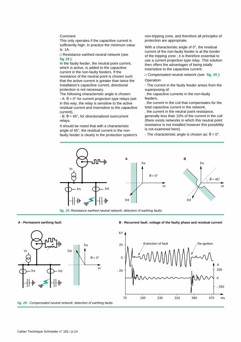
CommentThis only operates if the capacitive current issufficiently high. In practice the minimum valueis: 1A.v Resistance earthed neutral network (seefig 19 ):In the faulty feeder, the neutral point current,which is active, is added to the capacitivecurrent in the non-faulty feeders. If theresistance of the neutral point is chosen suchthat the active current is greater than twice theinstallation's capacitive current, directionalprotection is not necessary.The following characteristic angle is chosen:- A: θ = 0° for current projection type relays (setin this way, the relay is sensitive to the activeresidual current and insensitive to the capacitivecurrent),- B: θ = 45°, for directionalized overcurrentrelays.
It should be noted that with a characteristicangle of 45°, the residual current in the non-faulty feeder is clearly in the protection system's
non-tripping zone, and therefore all principles ofprotection are appropriate.
With a characteristic angle of 0°, the residualcurrent of the non-faulty feeder is at the borderof the tripping zone ; it is therefore essential touse a current projection type relay. This solutionthen offers the advantages of being totallyinsensitive to the capacitive current.
v Compensated neutral network (see fig. 20 ):
Operation- The current in the faulty feeder arises from thesuperposing of:. the capacitive currents in the non-faultyfeeders,. the current in the coil that compensates for thetotal capacitive current in the network,. the current in the neutral point resistance,generally less than 10% of the current in the coil(there exists networks in which this neutral pointresistance is not installed however this possibilityis not examined here).- The characteristic angle is chosen as: θ = 0°.
Ird
Irs
Irs
Vr
Vr
θ = 0°
AIrs
IrdIrd
Vr
θ = 45°
B
Irs
Irs
Ird
Vr
Vr
θ = 0°
Ird
A - Permanent earthing fault B - Recurrent fault: voltage of the faulty phase and residual current
70
- 20
20
kV
0
150 230 310 390 470
- 250
250
A
0
ms
Extinction of fault Re-ignition
fig. 19 : Resistance earthed neutral network: detection of earthing faults.
fig. 20 : Compensated neutral network: detection of earthing faults.

Cahier Technique Schneider n° 181 / p.15
CommentIt is essential to use current projection typeprotection equipment ;directional overcurrent protection equipment riskscausing spurious tripping.On this type of network, insulation faults are oftenrecurrent in nature : the fault arc will beextinguished after several milliseconds and re-ignite several periods later as part b of figure 20shows. Protection equipment must be speciallydesigned to function in the presence of this typeof fault.
v Directly earthed neutral networks (see fig. 21 ):
Operation- The neutral point current is mainly inductive. It ismuch greater than the network's capacitivecurrent,- The characteristic angle is chosen to be:θ = -45 to -90°.It should be noted that a simple zero sequenceovercurrent relay is sufficient to detect a faultyfeeder provided its threshold is set to a value thatis greater than the capacitive current of theprotected feeder.Directional relays are only used in a meshednetwork or in one having several neutral points.
Irs
Irs
Ird
Vr
Vrθ = - 70°
Ird
c Multiple earthing pointsCertain networks can be operated with theneutral earthed in several places. This is notablythe case when the neutral is earthed in eachenergy source (generator unit or incomertransformer). The parallel connection of sourcestherefore leads to the parallel connection of theneutral earthing connections.In this case, the selective protection of sourcesagainst earthing faults requires directionalearthing protection equipment on the incomer ofeach of the sources.Figure 22 shows the typical arrangemøent ofearthing fault protection equipment.The arrow indicates the direction of faultdetection in each directional earthing protectionequipment. The time delays on each piece ofequipment are also shown.The characteristic angles are chosen accordingto the neutral point arrangement : that of theprotection equipment located on the generatorset incomer according to the neutral earthingarrangement of the transformer and that of theprotection equipment installed on thetransformer incomer according to the neutralearthing arrangement of the alternator.
Ih >
0.4 s or more
0.1 s
Ih >
Ih >
0.4 s or more
0.1 s
Direction ofdetection Ih >
a
fig. 21 : Directly earthed neutral network: detection of earthing faults.
fig. 22 : Earthing fault protection on a network earthed at several points.
Cahier Technique Schneider n° 181 / p.16
protection is less costly and easier toincorporate. Note that the detection of earthingfaults is performed whatever the neutral pointarrangement of the installation, whereasdifferential line protection equipment has limitedsensitivity.
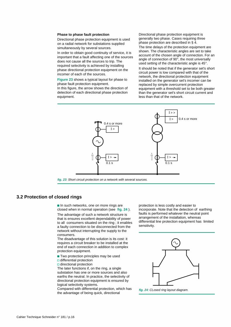
Phase to phase fault protectionDirectional phase protection equipment is usedon a radial network for substations suppliedsimultaneously by several sources.In order to obtain good continuity of service, it isimportant that a fault affecting one of the sourcesdoes not cause all the sources to trip. Therequired selectivity is achieved by installingphase directional protection equipment on theincomer of each of the sources.
Figure 23 shows a typical layout for phase tophase fault protection equipment.In this figure, the arrow shows the direction ofdetection of each directional phase protectionequipment.
Directional phase protection equipment isgenerally two phase. Cases requiring threephase protection are described in § 4.The time delays of the protection equipment areshown. The characteristic angles are set to takeaccount of the chosen angle of connection. For anangle of connection of 90°, the most universallyused setting of the characteristic angle is 45°.It should be noted that if the generator set's shortcircuit power is low compared with that of thenetwork, the directional protection equipmentinstalled on the generator set's incomer can bereplaced by simple overcurrent protectionequipment with a threshold set to be both greaterthan the generator set's short circuit current andless than that of the network.
0.1 s
I >
I >
0.4 s or more
0.4 s or more
0.1 s
I >
a
I > >
I >
fig. 23 : Short circuit protection on a network with several sources.
3.2 Protection of closed rings
c In such networks, one on more rings areclosed when in normal operation (see fig. 24 ).
The advantage of such a network structure isthat is ensures excellent dependability of powerto all consumers situated on the ring ; it enablesa faulty connection to be disconnected from thenetwork without interrupting the supply to theconsumers.The disadvantage of this solution is its cost: itrequires a circuit breaker to be installed at theend of each connection in addition to complexprotection equipment.
c Two protection principles may be usedv differential protectionv directional protectionThe later functions if, on the ring, a singlesubstation has one or more sources and alsoearths the neutral. In practice, the selectivity ofdirectional protection equipment is ensured bylogical selectivity systems.Compared with differential protection, which hasthe advantage of being quick, directional
fig. 24 : CLosed ring layout diagram.
a

Cahier Technique Schneider n° 181 / p.17
Parallel connected lines
Two parallel connected lines are the simplestand most frequently encountered example of aclosed ring.The protection system must bedesigned in such a way that a fault on one linedoes not cause the other line to trip.
A typical protection system is shown infigure 25 . In this figure, the arrow shows thedirection of detection of each directionalprotection equipment.
Directional phase protection equipment is of twophase type. Its characteristic angle is set to takeaccount of the chosen angle of connection(45° for an angle of connection of 90°).The characteristic angle of directional earthingprotection equipment is set according to theneutral point arrangement as explained in theprevious paragraphs.
The protection equipment time delays are shownin the figure. Non directional protectionequipment used on upstream substation feedersare time delayed so as to grade with thedirectional protection equipment of thedownstream substation incomers.
In the instance of a short circuit on one of thelines, the current is divided according to theimpedance in each circuit : part flows directly
from the upstream substation in the faulty line,the rest passes through the downstreamsubstation.The protection equipment is activated in thefollowing order :
c A1, D1 and D2 detect the fault,c A1 trips (time delay : 0.1 s),c D2 resets before its time delay has elapsed,c D1 trips (time delay : 0.4 s).
When a short circuit occurs near to the upstreamsubstation's busbars, the proportion of currentpassing through the downstream substation isvery low, less than the directional phaseprotection threshold value.This is the case when the position «x» of thefault is between 0 and twice the ratio of Is/Isc(between the directional protection relay'sthreshold and the short circuit current). In thiscase, the faulty line feeder's overcurrentprotection equipment (D1) trips first (time delay:0.4 s) with A1 tripping next.The total time to elimination of the fault istherefore prolonged. This disadvantage can beovercome by installing a second overcurrentrelay on feeders D1 and D2 with a high threshold(tripping for a Isc corresponding to less than90% of the length of the line) with a time delayof 0.1 s.
0.4 s
0.1 s
I >
Ih >
I >
Ih >
A2
D2
0.4 s
0.1 s
I >
Ih >
I >
Ih >
A1
D1
Fault's position
0
x %
100 %
fig. 25 : Protection of parallel connected lines.
Cahier Technique Schneider n° 181 / p.18
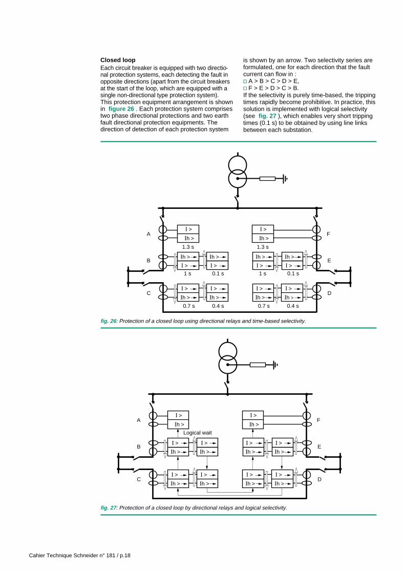
Closed loopEach circuit breaker is equipped with two directio-nal protection systems, each detecting the fault inopposite directions (apart from the circuit breakersat the start of the loop, which are equipped with asingle non-directional type protection system).This protection equipment arrangement is shownin figure 26 . Each protection system comprisestwo phase directional protections and two earthfault directional protection equipments. Thedirection of detection of each protection system
is shown by an arrow. Two selectivity series areformulated, one for each direction that the faultcurrent can flow in :v A > B > C > D > E,v F > E > D > C > B.If the selectivity is purely time-based, the trippingtimes rapidly become prohibitive. In practice, thissolution is implemented with logical selectivity(see fig. 27 ), which enables very short trippingtimes (0.1 s) to be obtained by using line linksbetween each substation.
fig. 26 : Protection of a closed loop using directional relays and time-based selectivity.
I >
Ih >
I >
Ih >
A F
B
C
E
D
1.3 s
I >
Ih >
1.3 s
1 s 0.1 s
0.7 s
I >
Ih >
0.4 s
I > I >
Ih > Ih >
I >
Ih >
0.7 s
I >
Ih >
0.4 s
1 s 0.1 sI > I >
Ih > Ih >
I >
Ih >
I >
Ih >
A F
B
C
E
D
I >
Ih >
I >
Ih >
Ih > Ih >
I > I >
I >
Ih >
I >
Ih >
Ih > Ih >
I > I >
Logical wait
fig. 27 : Protection of a closed loop by directional relays and logical selectivity.

Cahier Technique Schneider n° 181 / p.19
3.3 Protection of alternators
Detection of the loss of excitationThe break or the short circuiting of the excitationcoil of an alternator is a serious fault. It eithercauses the alternator to function as anasynchronous generator, or it stops theconversion of energy and causes an increase inspeed. The first case occurs if the excitationcircuit is short circuited or if the rotor has damperwindings; the situation is stable, but the machineis not designed to accept it for very long. In thesecond case, the situation is unstable and thedrive machine must be stopped as quickly aspossible.It is therefore necessary to monitor the excitationcircuit. Unfortunately, it is often inaccessible,located totally within the rotor (alternator withoutrings or brushes). We then use the measurementof the reactive power absorbed by the machineor the measurement of the impedance at itsterminals (see fig. 28 ).The reactive power measurement is most oftenused to protect low and medium powermachines. It detects any absorption of reactivepower and therefore any time the alternator isfunctioning as an asynchronous generator. Itmust be possible to set the threshold to a value
Q >
a
Positive directionof P and Q
Neutral pointof the machine
Q
P
lower than Sn (the machine's rated apparentpower) ; typically 0.4 Sn.
Detection of motor operationA generator set connected to a power networkcontinues to turn synchronously even if theprime mover (diesel or turbine) is no longerenergy supplied. The alternator then functions asa synchronous motor. Operating in such a waymay be detrimental to the prime mover.In order to detect such operation, a directionalactive power relay must be used (see fig. 29 ).The threshold of this protection equipment is setto a low value compared with the alternator'srated apparent power, typically between 5 and20%, sometimes less for turbo-alternators.Special attention must be given to the design ofthis very sensitive relay in order to ensurestability under all normal operatingcircumstances of the alternator.
Protection for parallel operationWhen an industrial installation has one orseveral generation equipments designed tooperate in parallel with the supply authoritynetwork, it is advisable to provide a specificprotection system.
P >
aQ
PPositive directionof P and Q
fig. 29 : Detection of motor operation, by an active reverse power relay.
fig. 28 : Protection against excitation losses by a reactive reverse power relay.
Cahier Technique Schneider n° 181 / p.20
This protection equipment has two objectives:c ensuring the safety of the production unit'spower station,c ensuring the safety of the main network, whichcan be supplied from the industrial premise'spower station.
This protection equipment is generally installedon the industrial network incomer circuit breaker,controlling its opening. It can also control theopening of a coupling circuit breaker betweentwo parts of the installation.
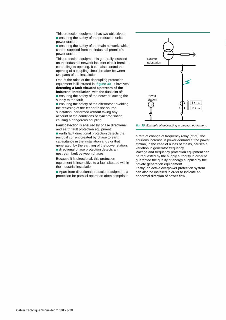
One of the roles of the decoupling protectionequipment is illustrated in figure 30 : it involvesdetecting a fault situated upstream of theindustrial installation , with the dual aim of:c ensuring the safety of the network: cutting thesupply to the fault,c ensuring the safety of the alternator : avoidingthe reclosing of the feeder to the sourcesubstation, performed without taking anyaccount of the conditions of synchronisation,causing a dangerous coupling.
Fault detection is ensured by phase directionaland earth fault protection equipment:c earth fault directional protection detects theresidual current created by phase to earthcapacitance in the installation and / or thatgenerated by the earthing of the power station,c directional phase protection detects anupstream fault between phases.
Because it is directional, this protectionequipment is insensitive to a fault situated withinthe industrial installation.
c Apart from directional protection equipment, aprotection for parallel operation often comprises
fig. 30 : Example of decoupling protection equipment.
I >
Ih >
Sourcesubstation
a
Powerstation
a rate of change of frequency relay (df/dt): thespurious increase in power demand at the powerstation, in the case of a loss of mains, causes avariation in generator frequency.Voltage and frequency protection equipment canbe requested by the supply authority in order toguarantee the quality of energy supplied by theprivate generation equipement.Lastly, an active overpower protection systemcan also be installed in order to indicate anabnormal direction of power flow.

Cahier Technique Schneider n° 181 / p.21
4 Use
4.1 Sizing of current and voltage transformers
The choice of VT's (voltage transformers) doesnot pose any particular problem.VT's normally installed on distribution networksare either of class 0.5 or 1; they are perfectlysuitable for the supply of directional protectionequipment as long as the sum of the loadsconnected to them is neither greater than theirrated burden, nor too low, in order to avoid risksof ferro-resonance.CT's (current transformers) are more tricky todesign for this purpose. Should they be under-designed and in the instance of a short circuitcurrent having an aperiodic component with ahigh time constant, the CT's become saturated.This phenomenon causes an error in the phasecurrent measurement during the transient, asshown in figure 31 .The current measured on the CT's secondarywinding always leads the primary current.
Incorrect design of CT's can have twoconsequences:c it may cause spurious tripping - a risk thatdecreases the longer the protection equipment'stime delay,c it may cause delayed tripping - a risk that isindependent of the selected time delay.The main factor influencing the protectionequipment's behaviour is the phasedisplacement α between the short circuit currentand the protection's tripping zone boundary line,as defined in figure 32 .
In practice, if this angle α is greater than 45°(which is very often the case with the recommen-ded settings), the design requirements for the CTare not so strict : choose the accuracy limit factorfor the CT (as defined in «Cahier Technique»n° 164) to be greater than or equal to 0.3 times thevalue of the maximum short circuit currentobserved by the directional protection equipment.
1
p.u.
Degrees
00.04
15
0
45
30
Time (s)
2
- 1
- 2
Angle error
0.02 0.06 0.08 0.10
Secondary CT current
α
I
V polarisation
Tripping zone
Characteristic axis
Characteristic angle
fig. 31 : Angle error calculated under the following conditions:c the fault comprises an aperiodic component of 100% and a time constant of 40 ms;c the CT's saturation current is twice the short circuit current.
fig. 32 : Definition of the angle α.
Cahier Technique Schneider n° 181 / p.22
4.2 Selection between two or three phase protection
With analog technology, directional phaseprotection equipment is often single phase: itmeasures the current in one single phase. It ispossible to equip one, two or all three phases witha relay.With digital technology, several protectionfunctions are integrated within one piece ofequipment: directional phase protectionequipment is most often two phase andsometimes three phase.As a general rule, when detecting an abnormaltransfer of power (protection of machines), the
phenomenon is balanced over the three phasesand therefore a single phase relay is sufficient.When wanting to detect a short circuit betweentwo phases, two phase directional protectionequipment is sufficient : at least one of the twophases will be involved in the fault.To detect a phase to earth fault, either threephase directional phase protection equipment orearthing protection equipment will be required. Ifthe installation's neutral is directly earthed, the firstsolution is often best suited. For all other neutralpoint arrangements, choose the second one.
4.3 Protection of parallel connected transformers
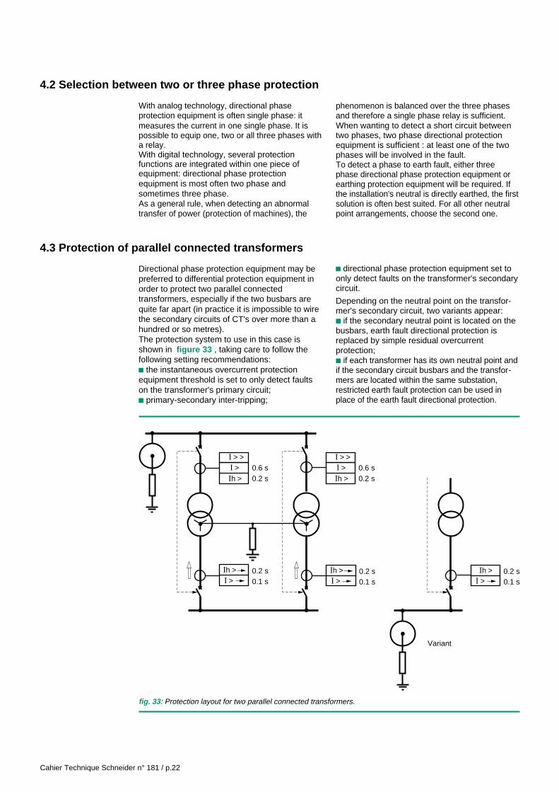
Directional phase protection equipment may bepreferred to differential protection equipment inorder to protect two parallel connectedtransformers, especially if the two busbars arequite far apart (in practice it is impossible to wirethe secondary circuits of CT's over more than ahundred or so metres).The protection system to use in this case isshown in figure 33 , taking care to follow thefollowing setting recommendations:c the instantaneous overcurrent protectionequipment threshold is set to only detect faultson the transformer's primary circuit;c primary-secondary inter-tripping;
c directional phase protection equipment set toonly detect faults on the transformer's secondarycircuit.
Depending on the neutral point on the transfor-mer's secondary circuit, two variants appear:c if the secondary neutral point is located on thebusbars, earth fault directional protection isreplaced by simple residual overcurrentprotection;c if each transformer has its own neutral point andif the secondary circuit busbars and the transfor-mers are located within the same substation,restricted earth fault protection can be used inplace of the earth fault directional protection.
fig. 33 : Protection layout for two parallel connected transformers.
0.2 s0.6 s
0.1 s0.2 s
I >I > >
Ih > 0.2 s0.6 sI >
I > >
Ih >
Ih >I > 0.1 s
0.2 sIh >I > 0.1 s
0.2 sIh >I >
Variant

Cahier Technique Schneider n° 181 / p.23
5. developments and outlook
5.1 Developments in protection equipment technology
The generalisation of integrated and digitalprotection equipment makes directionalprotection equipment simple and relativelyinexpensive to use. This type of protectionequipment is therefore now seen as presentingan excellent opportunity to improve both thepower transmitted through the network and thequality of service.For example, two lines, one to provide powerand the other to provide back-up, may now beoperated in parallel using directional protectionequipment.
Combining logical selectivity (ref.«Cahier Technique» n°2) and directionalprotection equipment enables systems to bedesigned that improve the dependability of theelectrical power.The appearance on the market of multiple-function relays (in other words ones combiningall the protection functions plus the requiredcontrol logic) that are dedicated to eachapplication, simplifies the design andincorporation of the protection system (seefig. 34 ).
fig. 34 : The SEPAM 2000, a multiple function digital relay enabling directional protection equipment to be usedcombined with logical selectivity.

Cahier Technique Schneider n° 181 / p.24
5.2 Developments in sensors
The advent of digital protection equipment,requiring very little power for measurements, hasenabled new sorts of sensors to be used.Rogowski coils (CT's without a core), becausethey do not become saturated, enable directionalphase protection equipment to retain itsmeasurement accuracy and to avoid angleerrors whatever the fault. The problem of sizingthe CT disappears.These measurement reducers, comprising alarge number of turns wound around an non-magnetic core, are described in «CahierTechnique» n°170.
Resistive voltage dividers, with their low cost andlow space requirements, are installed in cubicles,near to the directional protection equipment : thevoltage measurement cabling is much morereliable than when VT's are used: VT’s are nolonger a common failure mode of the protectionsystem.The development of sensors goes further tostrengthen the interest of directional protectionequipment, by improving performance levels andmaking them easier to incorporate.
5.3 In conclusion
Technological advances (digital protectionequipment, new sensors, etc.), as well as logicalselectivity make directional protection equipmenteasier to use.
Today, this high performance and easy toincorporate protection equipment is provinginvaluable in improving the dependability of the
electrical power supply. It is increasingly beingused to protect networks and machines, whetherfor phase to phase fault protection or for earthingfault protection.
Readers interested in more general informationon the various types of protection equipment usedin MV can refer to «Cahier Technique» n° 174.


Schneider Direction Scientifique et Technique,Service Communication TechniqueF-38050 Grenoble cedex 9Fax. (33) 04 76 57 98 60
Real.: Sodipe - ValenceEdition: SEST Grenoble03.98 - 1500 - Printing: ClercPrinted in France
© 1
998
Sch
neid
er
03-9888258