Caged Ball LM Guide Ultra-Heavy Load, High Rigidity Type ... · 2 Ultra-Heavy Load, High Rigidity...
32
CATALOG No.356-4E Caged Ball LM Guide Ultra-Heavy Load, High Rigidity Type Improved Dust Control Performance Optimized for Machine Tools SVR/SVS For details, visit THK at www.thk.com ˎProduct information is updated regularly on the THK website.
Transcript of Caged Ball LM Guide Ultra-Heavy Load, High Rigidity Type ... · 2 Ultra-Heavy Load, High Rigidity...

CATALOG No.356-4E
Caged Ball LM GuideUltra-Heavy Load, High Rigidity TypeImproved Dust Control PerformanceOptimized for Machine Tools SVR/SVS
For details, visit THK at www.thk.com*Product information is updated regularly on the THK website.
201-0503_H1-4_P1-3_4C 12.1.19 13:55 ページ h1

1
Caged Ball LM GuideMechanical motion of a machine is made up of two motions; Rotational motion and Linear motion. And these motions of machine hasevolved from “sliding” to “rolling.”“Rolling” in the rotational motion was realized with the advent of the ball bearing more than 100 years ago.Since then, the ball bearing has evolved from a full-ball type in the early years into a caged-ball type, which enables the balls to be evenlyaligned without being in contact with each other, resulting in drastic improvement of the performance.Concerning the linear motion, “LM Guide,” a linear motion guide that THK developed and commercialized in 1972, was adopted inindustrial equipment and various other machinery as an innovative product that realizes “rolling.”Since “LM Guide” evolved from a full-ball type into “Caged-Ball LM Guide” in 1996, its performance has also drastically beenimproved and the areas of its application has been broadened to various industrial fields.
Long Service Life and Long-termMaintenance-free Operation
Superbly High Speed
Low Noise, Acceptable Running Sound
Smooth Motion
Low Dust Generation
Extremely low bearing stressachieved with ball-to-cage contact
Oil-film contact
Full Ball structure Caged Ball structure
●Adjacent balls are in point contact with eachother. As a result, the surface pressure of thecontact region is high and the oil film easilybreaks.●Wear occurs due to friction between adjacent
balls.●Collision noise is produced due to contact
between adjacent balls.●the service life is short for the above reasons.
Since the friction between adjacent balls is eliminated,●The oil film does not easily break.●Friction wear is reduced.●Heat generation during high-speed operation is
suppressed.●Degradation of the lubricant is suppressed.●Collision noise is suppressed.●Balls move smoothly because they are evenly aligned.●Lubrication condition is improved by the ball cage.●The service life is longer for the above reasons.
Ball
High bearing stress due toball-to-ball contact
Feature of the Caged Ball LM Guide
201-0503_H1-4_P1-3_4C 12.1.19 13:55 ページ 1
2
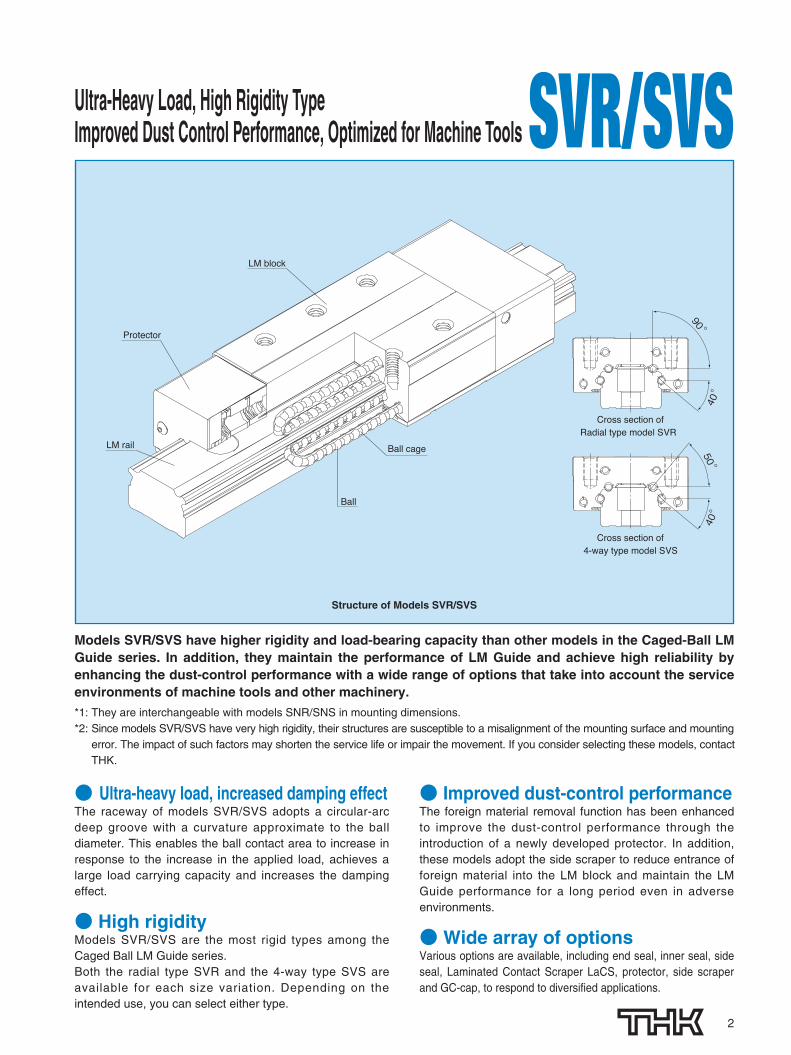
Ultra-Heavy Load, High Rigidity TypeImproved Dust Control Performance, Optimized for Machine Tools SVR/SVS
Models SVR/SVS have higher rigidity and load-bearing capacity than other models in the Caged-Ball LMGuide series. In addition, they maintain the performance of LM Guide and achieve high reliability byenhancing the dust-control performance with a wide range of options that take into account the serviceenvironments of machine tools and other machinery.*1: They are interchangeable with models SNR/SNS in mounting dimensions.*2: Since models SVR/SVS have very high rigidity, their structures are susceptible to a misalignment of the mounting surface and mounting
error. The impact of such factors may shorten the service life or impair the movement. If you consider selecting these models, contactTHK.
● Ultra-heavy load, increased damping effectThe raceway of models SVR/SVS adopts a circular-arcdeep groove with a curvature approximate to the balldiameter. This enables the ball contact area to increase inresponse to the increase in the applied load, achieves alarge load carrying capacity and increases the dampingeffect.
● High rigidityModels SVR/SVS are the most rigid types among theCaged Ball LM Guide series.Both the radial type SVR and the 4-way type SVS areavailable for each size variation. Depending on theintended use, you can select either type.
● Improved dust-control performanceThe foreign material removal function has been enhancedto improve the dust-control performance through theintroduction of a newly developed protector. In addition,these models adopt the side scraper to reduce entrance offoreign material into the LM block and maintain the LMGuide performance for a long period even in adverseenvironments.
●Wide array of optionsVarious options are available, including end seal, inner seal, sideseal, Laminated Contact Scraper LaCS, protector, side scraperand GC-cap, to respond to diversified applications.
50 。
90 。
40 。
40 。
Ball cage
Ball
Protector
LM rail
LM block
Cross section ofRadial type model SVR
Cross section of4-way type model SVS
Structure of Models SVR/SVS
201-0503_H1-4_P1-3_4C 12.1.19 13:55 ページ 2

3
TTHHYY OptionDouble Seal (→P.25~26)Laminated Contact Scraper LaCS (→P.25~26)Protector (→P.29) Side Scraper (→P.27)
After traveling 3000 km
Models SVR/SVS maintain their performance evenafter traveling 3000 km under severe conditions withexposure to coolant and contamination.
● Models SVR/SVS Contamination Protection Performance EvaluationModels SVR/SVS maintain their performance under severe condition with fine particle or liquid contamination.
0 1000
Tested model 2
Tested model 1
2000 3000
Distance traveled [km]
No damage after traveling 3000 km
4000 5000
Spray Water-soluble Coolant Release foreign material
Stroke
Tested model
Protector
LaCS
Double SealsSide Scraper
Item Description
Tested model SVS45LR1TTHHYYC1�2880LP�2set
Maximum speed
Stroke
Grease used
200m/min
2500mm
THK AFB-LF Grease
Environmentalconditions
Foreignmaterial
CoolantWater-soluble Coolant
Amount: 0.4g/20min
Type: Metal powder Particle diameter: 125 μm or less (Atomized Powder)
Amount: 0.2cc/10s
■Test conditions
■Models SVR/SVS with option (TTHHYY option)
■Test Result
Test equipment
Tested model
201-0503_H1-4_P1-3_4C 12.1.19 13:55 ページ 3

4
● Models SVR/SVS Rigidity Evaluation DataRigidity of Models SVR/SVS is equal to or higher than conventional 4 Way Equal Load LM guide.
【Rigidity Data】Rigidity in 4 directions (Radial, Reverse radial, Horizontal) is shown below.
■Radial rigidity
Load F
80
70
60
50
40
30
20
0 0 10 20 30 40 50 60
10
SVS 45L (preload: C0)
Def
lect
ion
[μm
]
Applied load F [kN]
SNS 45L (preload: C0)
Radial rigidity
■Reverse radial rigidity
Load F
Def
lect
ion
[μm
]
Applied load F [kN]
Reverse radial rigidity
SVS 45L (preload: C0)SNS 45L (preload: C0)
80
70
60
50
40
30
20
0 0 10 20 30 40 50 60
10
■Horizontal rigidity
Load F
80
70
60
50
40
30
20
0 0 10 20 30 40 50 60
10
SVS 45L (preload: C0)
Def
lect
ion
[μm
]
Applied load F [kN]
Horizontal rigidity
SNS 45L (preload: C0)
201-0503_P4-12_2C 12.1.19 14:11 ページ 4

5
Ultra-heavy load, high rigidity, and improved dust control performanceRadial type model SVR and 4-way type model SVS are available to select from.Major applications Machining center / NC lathe / grinding machine / penta-plano milling machine
SVR/SVS OutlineModels SVR/SVS - Product Overview
Models SVR-R/SVS-R
The LM block has a smaller width (W) andis equipped with tapped holes.It is suitable for places where space for thetable width is limited.
W
●SVR/SVS 25R●SVR/SVS 30R●SVR/SVS 35R
●SVR/SVS 45R●SVR/SVS 55R●SVR/SVS 65R
Models SVR-LR/SVS-LR
The LM block has the same sectionalshape as models SVR-R/SVS-R, but has alonger overall LM block length (L) and agreater rated load.
L
Models SVR-C/SVS-C
The flange of the LM block has tapped holes.It can be mounted from the top or thebottom.It can be used in places where the tablecannot have through holes for mountingbolts.
●SVR/SVS 25LR●SVR/SVS 30LR●SVR/SVS 35LR
●SVR/SVS 45LR●SVR/SVS 55LR●SVR/SVS 65LR
●SVR/SVS 25C●SVR/SVS 30C●SVR/SVS 35C
●SVR/SVS 45C●SVR/SVS 55C●SVR/SVS 65C
Models SVR-LC/SVS-LC
The LM block has the same sectionalshape as models SVR-C/SVS-C, but has alonger overall LM block length (L) and agreater rated load.
L
●SVR/SVS 25LC●SVR/SVS 30LC●SVR/SVS 35LC
●SVR/SVS 45LC●SVR/SVS 55LC●SVR/SVS 65LC
201-0503_P4-12_2C 12.1.19 14:11 ページ 5

6
SVR/SVS OUTLINEModels SVR/SVS - Product Overview
Build-to-order Models
L
W
M
Models SVR-LCH/SVS-LCHThe LM block has the same sectional shape as models SVR-CH/SVS-CH, but hasa longer overall LM block length (L) and a greater rated load.
Models SVR-CH/SVS-CH The height (M) and width (W) dimensions are the same as that of LM Guide modelsSHS and HSR, and the flange of the LM block has tapped holes.
Models SVR-LRH/SVS-LRHThe LM block has the same sectional shape as models SVR-RH/SVS-RH, but hasa longer overall LM block length (L) and a greater rated load.
Models SVR-RH/SVS-RHThe height (M) and width (W) dimensions are the same as that of LM Guide modelsSHS and HSR, and the LM block has tapped holes.
L
W
M
●SVR/SVS 35LRH●SVR/SVS 45LRH●SVR/SVS 55LRH
●SVR/SVS 35CH●SVR/SVS 45CH●SVR/SVS 55CH
●SVR/SVS 35LCH●SVR/SVS 45LCH●SVR/SVS 55LCH
●SVR/SVS 35RH●SVR/SVS 45RH●SVR/SVS 55RH
201-0503_P4-12_2C 12.1.19 14:11 ページ 6

7
*1: Dimensional table formodels SVR/SVS
Model SVR-R/LR→ pages13 to 14
Model SVS-R/LR→ pages15 to 16
Model SVR-C/LC→ pages17 to 18
Model SVS-C/LC→ pages19 to 20
Model SVR-RH/LRH→ pages21
Model SVS-RH/LRH→ pages21
Model SVR-CH/LCH→ pages 22
Model SVS-CH/LCH→ pages 22
PE :Equivalent load [N]⋅Reverse-radial direction
PL :Reverse-radial load [N]PT :Lateral load [N]X, Y :Equivalent factor (see table 1)
PE=X・PL+Y・PT
Equivalent Load
Models SVR/SVS are capable ofreceiving loads in all four directions:radial, reverse-radial and lateraldirections.
Their basic dynamic load ratings arerepresented by the symbols in the radialdirection indicated in the figure on the right,and the actual values are provided in thedimensional tables*1 for SVR/SVS. Thevalues in the reverse-radial and lateraldirections are obtained from the table.
When the LM block of model SVR receives a reverse-radial load and a lateral loadsimultaneously, the equivalent load is obtained from the equation below.
CL
PL PRC0L
C
C0
C0T
CT
PT
C0T
CT
PT
Radial directionReverse-radial direction
Lateral direction
Lateral direction
Rated Loads in All Directions
Rated Loads of Models SVR/SVS in All Directions
Direction
Radial direction
Reverse-radial direction
Lateral direction
Basic dynamic load rating
C
CL=0.64C
CT=0.47C
Basic static load rating
C0
C0L=0.64C0
C0T=0.38C0
Model SVRDirection
Radial direction
Reverse-radial direction
Lateral direction
Basic dynamic load rating
C
CL=0.84C
CT=0.92C
Basic static load rating
C0
C0L=0.84C0
C0T=0.85C0
Model SVS
Table 1 Equivalent Factor of Model SVRPE
Equivalent load in reverse-radial direction
X
1
Y
1.678
PE :Equivalent load [N]⋅Radial direction⋅Reverse-radial direction
PR :Radial load [N]PL :Reverse-radial load [N]PT :Lateral load [N]X, Y :Equivalent factor (see tables 2 and 3)
PE=X・PR(PL)+Y・PT
When the LM block of model SVS receives a radial load and a lateral load, or areverse-radial load and a lateral load, simultaneously, the equivalent load isobtained from the equation below.
Table 2 Equivalent Factor of Model SVS(When radial load and lateral load are applied)
PE X
1
Y
0.935
Table 3 Equivalent Factor of Model SVS(When reverse-radial load and lateral load are applied)
PE X
1
Y
1.02
Equivalent load in radial direction
Equivalent load in reverse-radial direction
201-0503_P4-12_2C 12.1.19 14:11 ページ 7

8
SVR/SVS OUTLINEModels SVR/SVS - Product Overview
Service lifeThe service life of an LM Guide is subject to variations even under the sameoperational conditions. Therefore, it is necessary to use the rated life definedbelow as a reference value for obtaining the service life of the LM Guide.
1.0
0.9
0.8
0.7
0.6
0.5
0.4
0.3
0.2
0.1
60 50 40 30 20 10Raceway hardness (HRC)
Har
dn
ess
fact
or
fH
Fig. 1 Hardness factor (fH)
■fH:Hardness factorTo ensure the achievement of the optimum load capacity of the LM Guide,the raceway hardness must be between 58 and 64 HRC.At hardness below this range, the basic dynamic and static load ratingsdecrease. Therefore, the rating values must be multiplied by therespective hardness factors (fH).Since the LM Guide has sufficient hardness, the fH value for the LM Guideis normally 1.0 unless otherwise specified.
■fC:Contact factorWhen multiple LM blocks are used in close contact with each other, it isdifficult to achieve uniform load distribution due to moment loads andmounting-surface accuracy. When using multiple blocks in close contactwith each other, multiply the basic load rating (C or C0) by thecorresponding contact factor indicated in Table 1.Note: When uneven load distribution is expected in a large machine, consider using a contact
factor from Table 1.
■fT:Temperature factorSince the service temperature of Caged Ball LM Guides is normally 80°Cor below, the fT value is 1.0.
■fW:Load factorIn general, reciprocating machines tend to produce vibrations or impactduring operation. It is especially difficult to accurately determine allvibrations generated during high-speed operation and impacts producedeach time the machine starts and stops. Therefore, where the effects ofspeed and vibration are estimated to be significant, divide the basicdynamic load rating (C) by a load factor selected from Table 2, whichcontains empirically obtained data.
●Rated lifeThe rated life means the total travel distancethat 90% of a group of units of the same LMGuide model can achieve without flaking(scale-like exfoliation on the metal surface)after individually running under the sameconditions.
●Service life timeOnce the rated life (L) has been obtained, theservice life time can be obtained using theequation on the right if the stroke length andthe number of reciprocations are constant.
L = ( · )3 50CPC
fH · fT · fC
fW
Lh =L 106
2 RS n1 60
L : Rated life [km]C : Basic dynamic load rating*1 [N]PC : Calculated load [N]fH : Hardness factor (see Fig. 1)fT : Temperature factorfC : Contact factor (see Table 1)fW : Load factor (see Table 2)
Lh : Service life time [h]Rs : Stroke length [mm]n1 : No. of reciprocations per min [min-1]
Table 1 Contact Factor (fC)
Table 2 Load Factor(fW)
Number of blocks used in close contact
2
3
4
5
6 or more
Normal use
Contact factor fC
0.81
0.72
0.66
0.61
0.6
1
Faint
Weak
Moderate
Strong
Very slowV≦0.25m/s
Slow0.25<V≦1m/s
Medium1<V≦2m/s
FastV>2m/s
1 to 1.2
1.2 to 1.5
1.5 to 2
2 to 3.5
Vibration/impact Speed (V) fW
*1: Basic dynamic load rating(C)
It refers to a load with aconstant magnitude anddirection under which therated life (L) of a group ofidentical LM Guide unitsindependently operating is50 km.
201-0503_P4-12_2C 12.1.19 14:11 ページ 8

9
*1: Preload
Preload is an internal loadapplied to the roll ingelements (balls, rollers, etc.)of an LM block in advance inorder to increase its rigidity. The clearance of all modelSVR/SVS units is adjustedto the designated valuebefore being shipped.Therefore, it is unnecessaryto adjust the preload.
Radial Clearance StandardSince the radial clearance of an LM Guidegreatly affects the running accuracy, loadcarrying capacity and rigidity of the LMGuide, it is important to select anappropriate clearance according to theapplication.
In general, selecting a negative clearance (i.e., apreload*1 is applied) while taking into accountpossible vibrations and impact generated fromreciprocating motion favorably affects the servicelife and the accuracy.
Radial clearance
25
30
35
45
55
65
– 3 to +2 – 6 to – 3 – 9 to – 6
– 4 to +2 – 8 to – 4 –12 to – 8
– 4 to +2 – 8 to – 4 –12 to – 8
– 5 to +3 –10 to – 5 –15 to –10
– 6 to +3 –11 to – 6 –16 to –11
– 8 to +3 –14 to – 8 –20 to –14
Unit: μm
Indication symbol Normal Light preload Moderate preload
Model No. No symbol C1 C0
201-0503_P4-12_2C 12.1.19 14:11 ページ 9

10
*1: Running parallelism
It refers to the parallelismerror between the LM blockand the LM rail datum planewhen the LM block travelsthe whole length of the LMrail with the LM rail securedon the reference datumplane using bolts.
*2: Difference in height M
It indicates the differencebetween the minimum andmaximum values of height(M) of each of the LMblocks used on the sameplane in combination.
*3: Difference in width W2
It indicates the differencebetween the minimum andmaximum values of thewidth (W2) between each ofthe LM blocks, mounted onone LM rail in combination,and the LM rail.
SVR/SVS OUTLINEModels SVR/SVS - Product Overview
Accuracy StandardThe accuracy of model SVR/SVS isspecified in terms of running parallelism (*1),dimensional tolerance for height and width,and height and width difference between apair (*2,*3) when two or more LM blocks areused on one rail or when two or more railsare mounted on the same plane.
The accuracy of model SVR/SVS is categorized intoNormal grade (no symbol), High-accuracy grade (H),Precision grade (P), Super precision grade (SP) andUltra precision grade (UP) by model numbers, asindicated in the table below.
A
D
C
W2
M
B
Model No.Accuracy standard
ItemPrecision grade
PHigh-accuracy grade
HNormal gradeNo Symbol
Super precision grade SP
Ultra precision grade UP
Unit: mm
Dimensional tolerance for height MDifference in height MDimensional tolerance for width W2
Difference in width W2
Running parallelism of surface Çagainst surface ÅRunning parallelism of surface Îagainst surface ıDimensional tolerance for height MDifference in height MDimensional tolerance for width W2
Difference in width W2
Running parallelism of surface Çagainst surface ÅRunning parallelism of surface Îagainst surface ı
Dimensional tolerance for height MDifference in height MDimensional tolerance for width W2
Difference in width W2
Running parallelism of surface Çagainst surface ÅRunning parallelism of surface Îagainst surface ı
as shown in the table below
as shown in the table below
as shown in the table below
as shown in the table below
as shown in the table below
as shown in the table below
0.007
0.007
0– 0.04
0– 0.03
0.007
0.007
0– 0.05
0– 0.04
0.01
0.01
0– 0.05
0– 0.05
0.02
0.025
0.025
0.03
±0.08
±0.07
±0.08
±0.07
0.03
0.03
±0.08
±0.08
0.015
0.015
0.015
0.015
±0.04
±0.03
±0.04
±0.04
0.02
0.02
±0.04
±0.04
0.005
0.005
0– 0.02
0– 0.015
0.005
0.005
0– 0.03
0– 0.025
0.007
0.007
0– 0.04
0– 0.04
0.003
0.003
0– 0.01
0– 0.01
0.003
0.003
0– 0.015
0– 0.015
0.005
0.005
0– 0.03
0– 0.03
253035
65
4555
LM rail length (mm) Running Parallelism Values
Above Or lessNormal grade High-accuracy grade Precision grade Super precision grade Ultra precision grade
No Symbol H P SP UP― 50 5 3 2 1.5 150 80 5 3 2 1.5 180 125 5 3 2 1.5 1
125 200 5 3.5 2 1.5 1200 250 6 4 2.5 1.5 1250 315 7 4.5 3 1.5 1315 400 8 5 3.5 2 1.5400 500 9 6 4.5 2.5 1.5500 630 11 7 5 3 2630 800 12 8.5 6 3.5 2800 1000 13 9 6.5 4 2.5
1000 1250 15 11 7.5 4.5 31250 1600 16 12 8 5 41600 2000 18 13 8.5 5.5 4.52000 2500 20 14 9.5 6 52500 3090 21 16 11 6.5 5.5
LM Rail Length and Running Parallelism for Models SVR/SVS Unit:μm
201-0503_P4-12_2C 12.1.19 14:11 ページ 10

Normally, the mounting base for the LM rail and the LM block has a datum planeon the side face of the shoulder of the base in order to allow easy installation andhighly accurate positioning.
The corner of the mounting shoulder must be machined to have a recess, or machined to besmaller than the corner radius "r," to prevent interference with the chamfer of the LM rail or the LMblock.
Shoulder Height of the Mounting Base and the Corner Radius
11
Shoulder for the LM rail Shoulder for the LM block
H3
r
r
H2
r
H1
r
Model No.Corner radius
r (max)
Shoulder height for the LM rail
H1
Shoulder height for the LM block
H2
H3
Unit: mm
25
30
35
45
55
65
0.5
1
1
1
1.5
1.5
4
5
6
8
10
10
5
5
6
8
10
10
5.5
7
9
11.6
14
15
201-0503_P4-12_2C 12.1.19 14:11 ページ 11

12
SVR/SVS OUTLINEModels SVR/SVS - Product Overview
Error Allowance in the Parallelism Between Two RailsThe following table shows errorallowances in parallelism (P) betweentwo rails that will not affect the servicelife in normal operation.
The values in the tables indicate the errorallowances in vertical level (S) between tworails per 500 mm of the axis-to-axis distance,and are proportional to the axis-to-axisdistances.
Error Allowance in Vertical Level Between Two Rails
P
S
500
Model No. Clearance C0 Clearance C1 Normal clearance
25
30
35
45
55
65
14
19
21
25
32
39
15
21
25
28
35
42
21
28
35
42
49
56
■Model SVR Unit: μm
Model No. Clearance C0 Clearance C1 Normal clearance
25
30
35
45
55
65
10
14
15
18
23
28
11
15
18
20
25
30
15
20
25
30
35
40
■Model SVS Unit: μm
Model No. Clearance C0 Clearance C1 Normal clearance
25
30
35
45
55
65
35
45
60
70
85
100
43
55
75
85
105
125
65
85
105
125
150
175
■Model SVR Unit: μm
Model No. Clearance C0 Clearance C1 Normal clearance
25
30
35
45
55
65
49
63
84
98
119
140
60
77
105
119
147
175
91
119
147
175
210
245
■Model SVS Unit: μm
201-0503_P4-12_2C 12.1.19 14:11 ページ 12

13
Models SVR-R/SVR-LRDimensional Table for Models SVR-R/SVR-LR
■ Example of model numbercoding
zModel number xType of LM block cNo. of LM blocks used on the same rail vWith QZ LubricatorbDust prevention accessory symbol (see page 25) nRadial clearance symbol (see page 7)mLM rail length (in mm) ,Accuracy symbol (see page 8) .Symbol for LM rail jointed use ⁄0No. of rails used on the same plane
Note This model number indicates that an LM block and an LM rail constitute one set (i.e., the required number of sets when 2rails are used in parallel is 2).Those models equipped with QZ Lubricator cannot have a grease nipple.
(K)
W
W2 W1
H3
B
M
T
C
LL1
(E) 4-S×R
4-φD0*1e0
φd2 N
M1h
φd1
F
f0
Model SVR-RModel SVR-R/LR
MCMA
MB
SVR45 LR 2 QZ TTHH C0 +1200L P T -Ⅱz , . ⁄0mnbvx c
Model No.
Outer dimensions LM block dimensions
Width
W
Length
L
SVR 25RSVR 25LRSVR 30RSVR 30LRSVR 35RSVR 35LRSVR 45RSVR 45LRSVR 55RSVR 55LRSVR 65RSVR 65LR
Height
M
31
38
44
52
63
75
50
60
70
86
100
126
82.8102
98120.5109.5135138.2171163.3200.5186246
B C S✕R L1 T K N f0 E e0 D0
Greasenipple
32
40
50
60
65
76
3550406050726080759570
110
M6✕8
M8✕10
M8✕12
M10✕17
M12✕18
M16✕20
61.480.672.194.679
104.5105137.8123.6160.8143.6203.6
9.7
9.7
11.7
14.7
17.7
21.6
25.5
31
35
40.4
49
60
7.8
10.3
12.1
13.9
16.6
19
5.1
7
8
8
10
15
12
12
12
16
16
16
4.5
6.5
6
8.5
10
8.7
3.9
3.9
5.2
5.2
5.2
8.2
H3
5.5
7
9
11.6
14
15
B-M6F
B-M6F
B-M6F
B-PT1/8
B-PT1/8
B-PT1/8
201-0503_P13-27_2C 12.1.20 8:54 ページ 13

14
Note *1 Pilot holes for side nipples are not drilled through in order to prevent foreign material from entering the product.THK will mount grease nipples per your request. Therefore, do not use the side nipple pilot holes for purposes other thanmounting a grease nipple.In case of oil lubrication, be sure to let THK know the mounting orientation and the exact position in each LM block wherethe piping joint should be attached.
*2 The maximum length under "Length" indicates the standard maximum length of an LM rail.*3 Static permissible moment: 1 block: Static permissible moment value with 1 LM block
Double blocks: Static permissible moment value with 2 blocks closely contacting with eachother
Unit: mm
W2
Height
M1
Pitch
Fd1✕d2✕h
LengthMax*2
C
[kN]
C0
[kN]
Basic load ratingLM rail dimensions Static permissible moment kN-m*3 Mass
25
28
34
45
53
63
12.5
16
18
20.5
23.5
31.5
17
21
24.5
29
36.5
43
40
80
80
105
120
150
2500
3000
3000
3090
3060
3000
6✕9.5✕8.5
7✕11✕9
9✕14✕12
14✕20✕17
16✕23✕20
18✕26✕22
4857688190
108132161177214260340
688699
126115159173231238312328481
0.5690.8900.8591.521.192.212.613.983.786.356.18
12.8
2.954.745.077.787.19
11.113.020.820.530.833.760.2
0.3910.6120.5881.040.8121.501.802.752.594.354.118.52
2.614.214.296.616.179.63
11.818.818.628.028.350.7
0.7200.9121.091.481.652.283.514.395.136.738.47
12.4
0.40.50.70.911.31.82.33.34.36.08.5
2.9
4.2
6.0
9.5
14
19.6
MA
1 block Doubleblocks
MB
1 block Doubleblocks
MC
1 block
LM block
[kg]
LM rail
[kg/m]
WidthW10
-0.05
Model SVR-LR
6-S×R
C
(E)
L1 e0
L
〃 〃
φd2
M1h
N f0
φd1
F
4-φD0*1
MA
201-0503_P13-27_2C 12.1.20 8:54 ページ 14

15
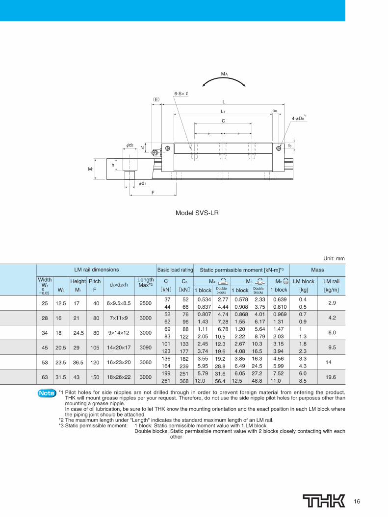
Models SVS-R/SVS-LRDimensional Table for Models SVS-R/SVS-LR
■ Example of model numbercoding
zModel number xType of LM block cNo. of LM blocks used on the same rail vWith QZ LubricatorbDust prevention accessory symbol (see page 25) nRadial clearance symbol (see page 7)mLM rail length (in mm) ,Accuracy symbol (see page 8) .Symbol for LM rail jointed use ⁄0No. of rails used on the same plane
Note This model number indicates that an LM block and an LM rail constitute one set (i.e., the required number of sets when 2rails are used in parallel is 2).Those models equipped with QZ Lubricator cannot have a grease nipple.
SVS45 LR 2 QZ TTHH C0 +1200L P T -Ⅱz , . ⁄0mnbvx c
Model No.
Outer dimensions LM block dimensions
Width
W
Length
L
SVS 25RSVS 25LRSVS 30RSVS 30LRSVS 35RSVS 35LRSVS 45RSVS 45LRSVS 55RSVS 55LRSVS 65RSVS 65LR
Height
M
31
38
44
52
63
75
50
60
70
86
100
126
82.8102
98120.5109.5135138.2171163.3200.5186246
B C S✕R L1 T K N f0 E e0 D0
Greasenipple
32
40
50
60
65
76
3550406050726080759570
110
M6✕8
M8✕10
M8✕12
M10✕17
M12✕18
M16✕20
61.480.672.194.679
104.5105137.8123.6160.8143.6203.6
9.7
9.7
11.7
14.7
17.7
21.6
25.5
31
35
40.4
49
60
7.8
10.3
12.1
13.9
16.6
19
5.1
7
8
8
10
15
12
12
12
16
16
16
4.5
6.5
6
8.5
10
8.7
3.9
3.9
5.2
5.2
5.2
8.2
H3
5.5
7
9
11.6
14
15
B-M6F
B-M6F
B-M6F
B-PT1/8
B-PT1/8
B-PT1/8
(K)
W
W2 W1
H3
B
M
T
C
LL1
(E) 4-S×R
4-φD0*1e0
φd2 N
M1h
φd1
F
f0
Model SVS-RModel SVS-R/LR
MAMC
MB
201-0503_P13-27_2C 12.1.20 8:54 ページ 15
16
Note *1 Pilot holes for side nipples are not drilled through in order to prevent foreign material from entering the product.THK will mount grease nipples per your request. Therefore, do not use the side nipple pilot holes for purposes other thanmounting a grease nipple.In case of oil lubrication, be sure to let THK know the mounting orientation and the exact position in each LM block wherethe piping joint should be attached.
*2 The maximum length under "Length" indicates the standard maximum length of an LM rail.*3 Static permissible moment: 1 block: Static permissible moment value with 1 LM block
Double blocks: Static permissible moment value with 2 blocks closely contacting with eachother
Basic load rating Static permissible moment [kN-m]*3
2.333.754.016.175.648.79
10.316.516.324.527.248.8
W2
Height
M1
Pitch
Fd1✕d2✕h
LM rail dimensions Mass
25
28
34
45
53
63
12.5
16
18
20.5
23.5
31.5
17
21
24.5
29
36.5
43
40
80
80
105
120
150
6✕9.5✕8.5
7✕11✕9
9✕14✕12
14✕20✕17
16✕23✕20
18✕26✕22
0.6390.8100.9691.311.472.033.153.944.565.997.52
11.0
0.40.50.70.911.31.82.33.34.36.08.5
2.9
4.2
6.0
9.5
14
19.6
Unit: mm
MC
1 block
LM block
[kg]
LM rail
[kg/m]
WidthW10
-0.05
LengthMax*2
2500
3000
3000
3090
3060
3000
MA
1 block Doubleblocks
MB
1 block Doubleblocks
6-S×R
C
(E)
L1 e0
L
〃 〃
φd2
M1h
N f0
φd1
F
4-φD0*1
Model SVS-LR
MA
5266769688
122133177182239251368
374452626983
101123136164199261
0.5340.8370.8071.431.112.052.453.743.555.955.79
12.0
2.774.444.747.286.78
10.512.319.619.228.831.656.4
C0
[kN]
C
[kN]
0.5780.9080.8681.551.202.222.674.083.856.496.05
12.5
201-0503_P13-27_2C 12.1.20 8:54 ページ 16

17
Models SVR-C/SVR-LCDimensional Table for Models SVR-C/SVR-LC
■ Example of model numbercoding
zModel number xType of LM block cNo. of LM blocks used on the same rail vWith QZ LubricatorbDust prevention accessory symbol (see page 25) nRadial clearance symbol (see page 7)mLM rail length (in mm) ,Accuracy symbol (see page 8) .Symbol for LM rail jointed use ⁄0No. of rails used on the same plane
Note This model number indicates that an LM block and an LM rail constitute one set (i.e., the required number of sets when 2rails are used in parallel is 2).Those models equipped with QZ Lubricator cannot have a grease nipple.
SVR45 LC 2 QZ TTHH C0 +1200L P T -Ⅱz , . ⁄0mnbvx c
Model No.
Outer dimensions LM block dimensions
Width
W
Length
L BGreasenipple
SVR 25CSVR 25LCSVR 30CSVR 30LCSVR 35CSVR 35LCSVR 45CSVR 45LCSVR 55CSVR 55LCSVR 65CSVR 65LC
Height
M
31
38
44
52
63
75
72
90
100
120
140
170
82.810298
120.5109.5135138.2171163.3200.5186246
59
72
82
100
116
142
C
45
52
62
80
95
110
S
M8
M10
M10
M12
M14
M16
H
6.8
8.5
8.5
10.5
12.5
14.5
L1
61.480.672.194.679
104.5105137.8123.6160.8143.6203.6
t
16
18.1
20.1
22.1
24
28
T
14.8
16.9
18.9
20.6
22.5
26
T1
12
14
16
20
22
25
K
25.5
31
35
40.4
49
60
N
7.8
10.3
12.1
13.9
16.6
19
f0
5.1
7
8
8
10
15
E
12
12
12
16
16
16
e0
4.5
6.5
6
8.5
10
8.7
D0
3.9
3.9
5.2
5.2
5.2
8.2
H3
5.5
7
9
11.6
14
15
B-M6F
B-M6F
B-M6F
B-PT1/8
B-PT1/8
B-PT1/8
B
W
T1
M
t T
W2 W1
(K)
H3
Model SVR-C/LC
MC
C
L1
(E) L
e0
Nφd2
4-φD0*1
4-S
(φH through)
M1
F
φd1
f0
h
Model SVR-C
MA
MB
201-0503_P13-27_2C 12.1.20 8:54 ページ 17

18
Note *1 Pilot holes for side nipples are not drilled through in order to prevent foreign material from entering the product.THK will mount grease nipples per your request. Therefore, do not use the side nipple pilot holes for purposes other thanmounting a grease nipple.In case of oil lubrication, be sure to let THK know the mounting orientation and the exact position in each LM block wherethe piping joint should be attached.
*2 The maximum length under "Length" indicates the standard maximum length of an LM rail.*3 Static permissible moment: 1 block: Static permissible moment value with 1 LM block
Double blocks: Static permissible moment value with 2 blocks closely contacting with eachother
W2
Height
M1
Pitch
Fd1×d2×h
C
[kN]
C0
[kN]
Basic load ratingLM rail dimensions Static permissible moment [kN-m]*3 Mass
25
28
34
45
53
63
23.5
31
33
37.5
43.5
53.5
17
21
24.5
29
36.5
43
40
80
80
105
120
150
6✕9.5✕8.5
7✕11✕9
9✕14✕12
14✕20✕17
16✕23✕20
18✕26✕22
4857688190
108132161177214260340
688699
126115159173231238312328481
0.5690.8900.8591.521.192.212.613.983.786.356.18
12.8
2.954.745.077.787.19
11.113.020.820.530.833.760.2
0.3910.6120.5881.040.8121.501.802.752.594.354.118.52
2.614.214.296.616.179.63
11.818.818.628.028.350.7
0.7200.9121.091.481.652.283.514.395.136.738.47
12.4
0.60.81.11.51.622.73.64.55.97.8
11.0
2.9
4.2
6.0
9.5
14
19.6
Unit: mm
MC
1 block
LM block
[kg]
LM rail
[kg/m]
WidthW10
-0.05
LengthMax*2
2500
3000
3000
3090
3060
3000
MA
1 block Doubleblocks
MB
1 block Doubleblocks
C4-φD0
*1
L
e0
(E)
L1
6-S
(φH through)
〃 〃
N f0
F
φd1
φd2
hM1
Model SVR-LC
MA
201-0503_P13-27_2C 12.1.20 8:54 ページ 18

19
Models SVS-C/SVS-LCDimensional Table for Models SVS-C/SVS-LC
■ Example of model numbercoding
zModel number xType of LM block cNo. of LM blocks used on the same rail vWith QZ LubricatorbDust prevention accessory symbol (see page 25) nRadial clearance symbol (see page 7)mLM rail length (in mm) ,Accuracy symbol (see page 8) .Symbol for LM rail jointed use ⁄0No. of rails used on the same plane
Note This model number indicates that an LM block and an LM rail constitute one set (i.e., the required number of sets when 2rails are used in parallel is 2).Those models equipped with QZ Lubricator cannot have a grease nipple.
SVS45 LC 2 QZ TTHH C0 +1200L P T -Ⅱz , . ⁄0mnbvx c
Model No.
Outer dimensions LM block dimensions
Width
W
Length
L BGreasenipple
SVS 25CSVS 25LCSVS 30CSVS 30LCSVS 35CSVS 35LCSVS 45CSVS 45LCSVS 55CSVS 55LCSVS 65CSVS 65LC
Height
M
31
38
44
52
63
75
72
90
100
120
140
170
82.8102
98120.5109.5135138.2171163.3200.5186246
59
72
82
100
116
142
C
45
52
62
80
95
110
S
M8
M10
M10
M12
M14
M16
H
6.8
8.5
8.5
10.5
12.5
14.5
L1
61.480.672.194.679.0
104.5105.0137.8123.6160.8143.6203.6
t
16
18.1
20.1
22.1
24
28
T
14.8
16.9
18.9
20.6
22.5
26
T1
12
14
16
20
22
25
K
25.5
31
35
40.4
49
60
N
7.8
10.3
12.1
13.9
16.6
19
f0
5.1
7
8
8
10
15
E
12
12
12
16
16
16
e0
4.5
6.5
6
8.5
10
8.7
D0
3.9
3.9
5.2
5.2
5.2
8.2
H3
5.5
7
9
11.6
14
15
B-M6F
B-M6F
B-M6F
B-PT1/8
B-PT1/8
B-PT1/8
B
W
T1
M
t T
W2 W1
(K)
H3
Model SVS-C/LC
MC
C
L1
(E) L
e0
Nφd2
4-φD0*1
4-S
(φH through)
M1
F
φd1
f0
h
Model SVS-C
MA
MB
201-0503_P13-27_2C 12.1.20 8:54 ページ 19

20
Note *1 Pilot holes for side nipples are not drilled through in order to prevent foreign material from entering the product.THK will mount grease nipples per your request. Therefore, do not use the side nipple pilot holes for purposes other thanmounting a grease nipple.In case of oil lubrication, be sure to let THK know the mounting orientation and the exact position in each LM block wherethe piping joint should be attached.
*2 The maximum length under "Length" indicates the standard maximum length of an LM rail.*3 Static permissible moment: 1 block: Static permissible moment value with 1 LM block
Double blocks: Static permissible moment value with 2 blocks closely contacting with eachother
W2
Height
M1
Pitch
Fd1✕d2✕h
C
[kN]
C0
[kN]
Basic load ratingLM rail dimensions Static permissible moment [kN-m]*3 Mass
25
28
34
45
53
63
23.5
31
33
37.5
43.5
53.5
17
21
24.5
29
36.5
43
40
80
80
105
120
150
6✕9.5✕8.5
7✕11✕9
9✕14✕12
14✕20✕17
16✕23✕20
18✕26✕22
374452626983
101123136164199261
5266769688
122133177182239251368
0.5340.8370.8071.431.112.052.453.743.555.955.79
12.0
2.774.444.747.286.78
10.512.319.619.228.831.656.4
0.5780.9080.8681.551.202.222.674.083.856.496.05
12.5
2.333.754.016.175.648.79
10.316.516.324.527.248.8
0.6390.8100.9691.311.472.033.153.944.565.997.52
11.0
0.60.81.11.51.522.73.64.55.97.8
11.0
2.9
4.2
6.0
9.5
14
19.6
Unit: mm
MC
1 block
LM block
[kg]
LM rail
[kg/m]
WidthW10
-0.05
LengthMax*2
2500
3000
3000
3090
3060
3000
MA
1 block Doubleblocks
MB
1 block Doubleblocks
C4-φD0
*1
L
e0
(E)
L1
6-S
(φH through)
〃 〃
N f0
F
φd1
φd2
hM1
Model SVS-LC
MA
201-0503_P13-27_2C 12.1.20 8:54 ページ 20

MC
MB
MA
21
Models SVR-RH/SVR-LRH SVS-RH/SVS-LRHDimensional Table for Models SVR-RH/SVR-LRH SVS-RH/SVS-LRHBuild-to-order Models
Model No.
Outer dimensions LM block dimensions
SVR 35RHSVS 35RHSVR 35LRHSVS 35LRHSVR 45RHSVS 45RHSVR 45LRHSVS 45LRHSVR 55RHSVS 55RHSVR 55LRHSVS 55LRH
W2
Height
M1
Pitch
Fd1✕d2✕h
C
[kN]
C0
[kN]
Basic load ratingLM rail dimensions Static permissible moment [kN-m]*3 Mass
34
34
45
45
53
53
18
18
20.5
20.5
23.5
23.5
24.5
24.5
29
29
36.5
36.5
80
80
105
105
120
120
9✕14✕12
9✕14✕12
14✕20✕17
14✕20✕17
16✕23✕20
16✕23✕20
9069
10883
132101161123177136214164
11588
159122173133231177238182312239
1.191.112.212.052.612.453.983.743.783.556.355.95
7.196.78
11.110.513.012.320.819.620.519.230.828.8
0.8121.201.502.221.802.672.754.082.593.854.356.49
6.175.649.638.79
11.810.318.816.518.616.328.024.5
1.651.472.282.033.513.154.393.945.134.566.735.99
1.5
2
3.2
4.1
4.7
6.2
6.0
6.0
9.5
9.5
14
14
MC
1 block
LM block
[kg]
LM rail
[kg/m]LengthMax*2
3000
3000
3090
3090
3060
3060
WidthW
LengthL B C S✕R L1 T K N f0 E e0 D0
Greasenipple
HeightM
55
55
70
70
80
80
70
70
86
86
100
100
109.5
135
138.2
171
163.3
200.5
50
50
60
60
75
75
50
72
60
80
75
95
M8✕12
M8✕12
M10✕17
M10✕17
M12✕18
M12✕18
79
104.5
105
137.8
123.6
160.8
11.7
11.7
14.7
14.7
17.7
17.7
46
46
58.4
58.4
66
66
23.1
23.1
31.9
31.9
33.6
33.6
19
19
26
26
27
27
12
12
16
16
16
16
6
6
8.5
8.5
10
10
5.2
5.2
5.2
5.2
5.2
5.2
H3
9
9
11.6
11.6
14
14
B-M6F
B-M6F
B-PT1/8
B-PT1/8
B-PT1/8
B-PT1/8
MA
1 block Doubleblocks
MB
1 block Doubleblocks
M
WB
(K)
W2 W1
4-S×R
H3
T
hM1
N
L1C
f0
φd1F
4-φD0*1(E) L
e0
φd2
WidthW10-0.05
Model No.
SVR 35RHSVS 35RHSVR 35LRHSVS 35LRHSVR 45RHSVS 45RHSVR 45LRHSVS 45LRHSVR 55RHSVS 55RHSVR 55LRHSVS 55LRH
■ Example of model numbercoding
zModel number xType of LM block cNo. of LM blocks used on the same rail vWith QZ LubricatorbDust prevention accessory symbol (see page 25) nRadial clearance symbol (see page 7)mLM rail length (in mm) ,Accuracy symbol (see page 8) .Symbol for LM rail jointed use ⁄0No. of rails used on the same plane
Note This model number indicates that an LM block and an LM rail constitute one set (i.e., the required number of sets when 2 railsare used in parallel is 2).Those models equipped with QZ Lubricator cannot have a grease nipple.
SVR35 RH 2 QZ TTHH C0 +920L H T -Ⅱz , . ⁄0mnbvx c
Note *1 Pilot holes for side nipples are not drilled through in order to prevent foreign material from entering the product.THK will mount grease nipples per your request. Therefore, do not use the side nipple pilot holes for purposes other thanmounting a grease nipple.In case of oil lubrication, be sure to let THK know the mounting orientation and the exact position in each LM block where thepiping joint should be attached.
*2 The maximum length under "Length" indicates the standard maximum length of an LM rail.*3 Static Permissible moment: 1 block: Static permissible moment value with 1 LM block
Double blocks: Static permissible moment value with 2 blocks closely contacting with each other
Unit: mm
201-0503_P13-27_2C 12.1.20 8:54 ページ 21
22
MC
MB
MA
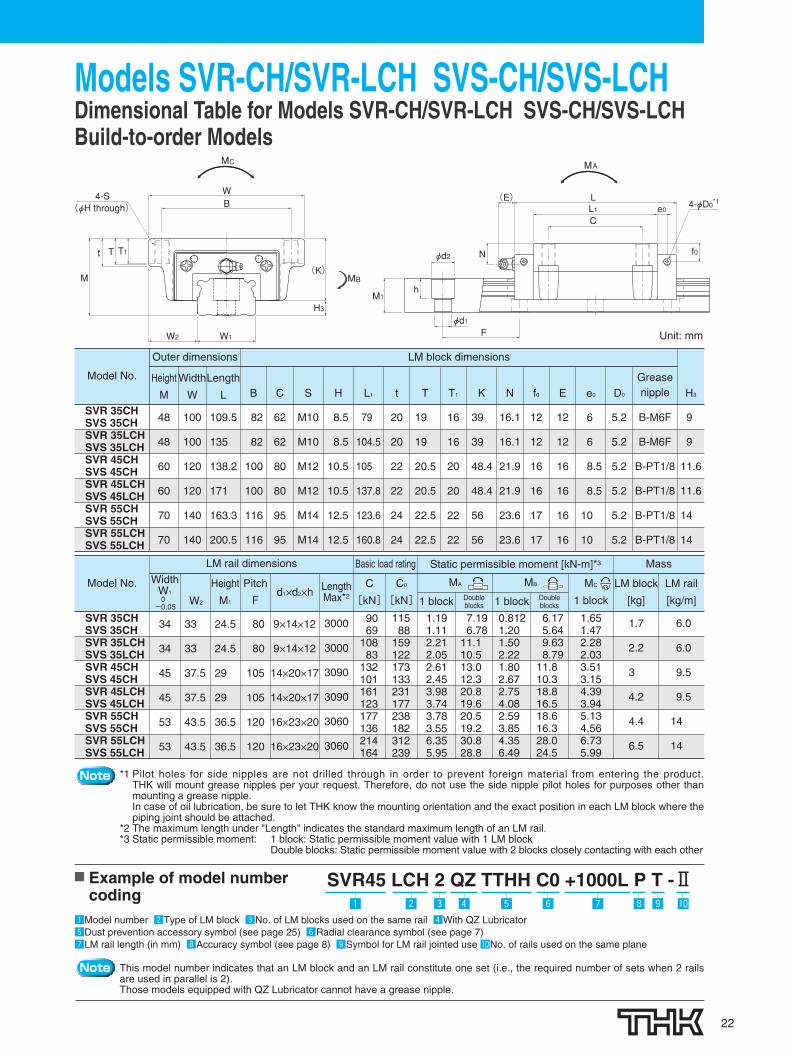
Models SVR-CH/SVR-LCH SVS-CH/SVS-LCHDimensional Table for Models SVR-CH/SVR-LCH SVS-CH/SVS-LCHBuild-to-order Models
Note *1 Pilot holes for side nipples are not drilled through in order to prevent foreign material from entering the product.THK will mount grease nipples per your request. Therefore, do not use the side nipple pilot holes for purposes other thanmounting a grease nipple.In case of oil lubrication, be sure to let THK know the mounting orientation and the exact position in each LM block where thepiping joint should be attached.
*2 The maximum length under "Length" indicates the standard maximum length of an LM rail.*3 Static permissible moment: 1 block: Static permissible moment value with 1 LM block
Double blocks: Static permissible moment value with 2 blocks closely contacting with each other
■ Example of model numbercoding
zModel number xType of LM block cNo. of LM blocks used on the same rail vWith QZ LubricatorbDust prevention accessory symbol (see page 25) nRadial clearance symbol (see page 7)mLM rail length (in mm) ,Accuracy symbol (see page 8) .Symbol for LM rail jointed use ⁄0No. of rails used on the same plane
Note This model number indicates that an LM block and an LM rail constitute one set (i.e., the required number of sets when 2 railsare used in parallel is 2).Those models equipped with QZ Lubricator cannot have a grease nipple.
Model No.
Outer dimensions LM block dimensions
SVR 35CHSVS 35CHSVR 35LCHSVS 35LCHSVR 45CHSVS 45CHSVR 45LCHSVS 45LCHSVR 55CHSVS 55CHSVR 55LCHSVS 55LCH
W2
Height
M1
Pitch
Fd1✕d2✕h
C
[kN]
C0
[kN]
Basic load ratingLM rail dimensions Static permissible moment [kN-m]*3 Mass
34
34
45
45
53
53
33
33
37.5
37.5
43.5
43.5
24.5
24.5
29
29
36.5
36.5
80
80
105
105
120
120
9✕14✕12
9✕14✕12
14✕20✕17
14✕20✕17
16✕23✕20
16✕23✕20
9069
10883
132101161123177136214164
11588
159122173133231177238182312239
1.191.112.212.052.612.453.983.743.783.556.355.95
7.196.78
11.110.513.012.320.819.620.519.230.828.8
0.8121.201.502.221.802.672.754.082.593.854.356.49
6.175.649.638.79
11.810.318.816.518.616.328.024.5
1.651.472.282.033.513.154.393.945.134.566.735.99
1.7
2.2
3
4.2
4.4
6.5
6.0
6.0
9.5
9.5
14
14
Unit: mm
MC
1 block
LM block
[kg]
LM rail
[kg/m]
WidthW10-0.05
LengthMax*2
3000
3000
3090
3090
3060
3060
Width
W
Length
L BGreasenipple
Height
M
48
48
60
60
70
70
100
100
120
120
140
140
109.5
135
138.2
171
163.3
200.5
82
82
100
100
116
116
C
62
62
80
80
95
95
S
M10
M10
M12
M12
M14
M14
H
8.5
8.5
10.5
10.5
12.5
12.5
L1
79
104.5
105
137.8
123.6
160.8
t
20
20
22
22
24
24
T
19
19
20.5
20.5
22.5
22.5
T1
16
16
20
20
22
22
K
39
39
48.4
48.4
56
56
N
16.1
16.1
21.9
21.9
23.6
23.6
f0
12
12
16
16
17
17
E
12
12
16
16
16
16
e0
6
6
8.5
8.5
10
10
D0
5.2
5.2
5.2
5.2
5.2
5.2
H3
9
9
11.6
11.6
14
14
B-M6F
B-M6F
B-PT1/8
B-PT1/8
B-PT1/8
B-PT1/8
MA
1 block Doubleblocks
MB
1 block Doubleblocks
SVR45 LCH 2 QZ TTHH C0 +1000L P T -Ⅱz , . ⁄0mnbvx c
(K)
T1
M
t T
W2 W1
BW
(φH through)
H3
4-S
φd2
φd1
M1
F
N
h
4-φD0*1e0
f0
(E)
CL1L
SVR 35CHSVS 35CHSVR 35LCHSVS 35LCHSVR 45CHSVS 45CHSVR 45LCHSVS 45LCHSVR 55CHSVS 55CHSVR 55LCHSVS 55LCH
Model No.
201-0503_P13-27_2C 12.1.20 8:54 ページ 22

23
Standard Length and Maximum Length of the LM RailThe table below shows the standard LM rail lengths and the maximum lengths of models SVR/SVSvariations. If the maximum length of the desired LM rail exceeds them, connected rails will be used.Contact THK for details.For the G dimension when a special length is required, we recommend selecting the corresponding Gvalue from the table. The longer the G dimension is, the less stable the G area may become afterinstallation, thus adversely affecting accuracy.
G F GF
L0
Standard Length and Maximum Length of the LM Rail for Models SVR/SVS Unit: mm
Note 1: The maximum length varies with accuracy grades. Contact THK for details.Note 2: If connected rails are not allowed and a greater length than the maximum values above is required, contact THK.
Model No.
Standard pitch F 4015
2500
8020
3000
8020
3000
10522.5
3090
120 15030 35
3060 3000
GMax length
SVR/SVS 25
230270350390470510590630710750830950990
107011101190123013101350143014701550159017101830195020702190231024302470
SVR/SVS 30
280360440520600680760840920
10001080116012401320140014801560164017201800188019602040220023602520268028403000
SVR/SVS 35
280360440520600680760840920
10001080116012401320140014801560164017201800188019602040220023602520268028403000
SVR/SVS 45
570675780885990
10951200130514101515162017251830193520402145225023552460256526702775288029853090
SVR/SVS 55
780900
102011401260138015001620174018601980210022202340246025802700282029403060
SVR/SVS 65
1270157020202620
Sta
ndar
d LM
rai
l len
gth
(L0)
201-0503_P13-27_2C 12.1.20 8:54 ページ 23

24
SVR/SVS OPTIONSOptionsFor models SVR/SVS, dust-prevention and lubrication accessories are available. Make a selection according to the application and theinstallation site.
GC Caps exclusivelyfor LM rail mounting holes
*Requires special GC Rail
9
Laminated Contact Scraper LaCS5
Protector10
41 End seal
QZ Lubricator 11
8
Side scraper case
Side scraper unit
Inner seal 3
Side seal2
6
7
Simplified bellows
Metal scraper
201-0503_P13-27_2C 12.1.20 8:54 ページ 24

25
When foreign matter enters an LM system, it will cause abnormal wear or shorten the service life. Itis necessary to prevent foreign matter from entering the system. Therefore, when possible entranceof foreign matter is predicted, it is important to select an effective sealing device or dust-preventiondevice that meets the working conditions.
Dust Prevention Accessories
Table 3 Symbols of Dust Prevention Accessories for Models SVR/SVSSymbol
UUSSDDZZKK
SSHHDDHHJJHHTTHH
JJHHYYTTHHYY
Dust prevention accessoryWith end sealWith end seal + side seal + inner sealWith double seals + side seal + inner sealWith end seal + side seal + inner seal + metal scraperWith double seals + side seal + inner seal + metal scraperWith end seal + side seal + inner seal+LaCSWith double seals + side seal + inner seal+LaCSWith end seal + side seal + inner seal + LaCS + protector (serving also as metal scraper)With double seals + side seal + inner seal + LaCS + protector (serving also as metal scraper)With end seal + side seal + inner seal + LaCS + protector (serving also as metal scraper) + side scraperWith double seals + side seal + inner seal + LaCS + protector (serving also as metal scraper) + side scraper
Seal resistance valueFor the maximum seal resistancevalue per LM block when a lubricantis applied on seal SVR/SVS … SS,refer to the corresponding valueprovided in table 1.
Table 1 Maximum Seal Resistance Valueof Seal SVR/SVS … SS
z to v SealsHighly wear-resistant end seals made of special resin rubber andside seals for increased dust-prevention effect are available.
If desiring a dust-prevention accessory, specify it with thecorresponding symbol indicated in table 3.For the supported LM Guide model numbers for dust-preventionaccessories and the overall LM block length with a dust-preventionaccessory attached (dimension L), see tables 4 and 5.
Seals and Scrapers
Model No.253035455565
Maximum seal resistance101418222631
Unit: N
End seal
End sealUsed in locations exposed todust.
Side sealUsed in locations where dustmay enter the LM block from theside or bottom surface, such asvertical, horizontal and invertedmount.
Inner sealUsed in locations severelyexposed to dust or cutt ingchips.
Side seal
Inner seal
1
2
3
Table 2 Resistance of LaCS (for Reference)
Model No.253035455565
Resistance of LaCS8.1
13.415.523.328.639.6
Unit: N
Note 1: Each resistance value in the tableonly consists of that of LaCS, anddoes not include slidingresistances of seals and otheraccessories.
Note 2: For the maximum service speedof LaCS, contact THK.
*Note that LaCS is not sold alone.
*Conventional ZZHH and KKHH specifications are also available. Contact THK for details.
bn ScrapersLaminated Contact Scraper LaCS®For locations with an even more adverse working conditions, theLaminated Contact Scraper LaCS is available.LaCS removes minute foreign matter adhering to the LM rail inmultiple stages and prevents it from entering the LM block with alaminated contact structure (3-layer scraper).
Features●Since the 3 layers of scrapers fully
contact the LM rail, LaCS is highlycapable of removing minuteforeign matter.●Since it uses oil-impregnated,
foam synthetic rubber with a self-lubricating function, low frictionresistance is achieved.
Basic Specifications of LaCS●Service temperature range of
LaCS: -20°C to +80°C●Resistance of LaCS (for Reference):
indicated in table 2
201-0503_P13-27_2C 12.1.20 8:54 ページ 25

OPTIONSOptions
26
構造図
LaCSUsed in harsh environmentsexposed to foreign matter suchas fine dust and liquids.
5
Metal scraperUsed in locations where weldingspatter may adhere to the LM rail.
6
Metal scraper
Double sealsUsed in locations exposed tomuch dust or many cutting chips.
End seal
4
:Datum planeKProtector Protector
Grease nipple
H
Note: When desiring the mounting location for the grease nipple other than the one indicated in thefigure above, contact THK.
Note: Protector also serves as a metal scraper.Note: The same incremental dimensions apply to SSHH and DDHH specifications which are
without a protector.
■When Dust Prevention Accessories HH, TTHH,JJHHYY or TTHHYY are Attached
When dust prevention accessories HH, TTHH, JJHHYY or TTHHYY areattached, the grease nipple can be mounted in the location indicated in the figurebelow. The table below shows incremental dimensions with the grease nipple.
■For Models Attached with Contamination Protection Accessories UU or SSFor the mounting location of the grease nipple (N) and itsincrementaldimension (E) when contamination protection accessoriesUU or SS areattached, see the corresponding dimensional table (seepage 11 to 22).
■For Models Attached with Contamination Protection Accessories DD, ZZ or KKFor the mounting location of the grease nipple and its incrementaldimension whencontamination protection accessories DD, ZZ or KKare attached, contact THK.*For other specifications with a protector attached, conventional ZZHH and KKHH specificationsare also available. Contact THK for details.
Table 4 Overall LM Block Length (Dimension L) of Models SVR/SVSwith a Dust Prevention Accessory Attached
UU SS DD ZZ KK SSHH DDHH JJHH* TTHH*Unit: mm
88107.2104.6127.1116.5142145.2178168.4205.6191.8251.8
82.810298
120.5109.5135138.2171163.3200.5186246
82.8102
98120.5109.5135138.2171163.3200.5186246
Model No.25R/C25LR/LC30R/C30LR/LC
35R/C/RH/CH35LR/LC/LRH/LCH45R/C/RH/CH45LR/LC/LRH/LCH55R/C/RH/CH55LR/LC/LRH/LCH
65R/C65LR/LC
Contact scraperBall
Ball cage
Liquid
Large amount of foreign matter
Structural drawing
Model No.
Incrementaldimension withgrease nipple
H
Nipple type
25R/LR30R/LR
35R/LR, RH/LRH45R/LR, RH/LRH55R/LR, RH/LRH
65R/LR
SVR/SVS
PB1021BPB1021B
A-M6FA-M6FA-M6F
A-PT1/8
5.55.5999
12
Unit: mm
107.7126.9127.5150140.5166172.8205.6198.1235.3224.9284.9
102.5121.7120.9143.4133.5159165.8198.6191.1228.3217.5277.5
102121.2121.8144.3133.7159.2165.2198189.4226.6216.2276.2
96.8116115.2137.7126.7152.2158.2191182.4219.6208.8268.8
93.7112.9110.3132.8123.3148.8152.8185.6176213.2200.5260.5
88.5107.7103.7126.2116.3141.8145.8178.6169206.2193.1253.1
*The overall LM block length (L) of YY type (with side scraper) is also the same.
201-0503_P13-27_2C 12.1.20 8:54 ページ 26

27
● Minimizes foreign material entering from the side of the LMGuide in a harsh environment.
● Demonstrates a dust protection effect in inverted or wallmount.
m Side ScraperSide Scraper7
Protector
LaCS
End seal
QZ Lubricator
End plate
Side scraper unit
Side scraper case
Side Scraper Configuration(Options shown: QZTTHHYY)
Side view of the LM block after the sidescraper is mounted
H1H3
r
r
Side face of the LM block
Foreign material
Foreign material
Foreignmaterial
Inverted mount Wall mount
Route of entrance by foreign material fromthe side face of the LM block
Note: The side scraper is not sold separately. Side scraper option need to bespecified at the time of order.
■ Model number codingSVR45 LR 1 QZ JJHH YY C1 +1200L
With a side scraper
Model No.Corner radiusr (maximum)
Shoulder height of theLM rail section
H1H3
253035455565
0.51111.51.5
23.55.58
10.511
2.74.26.28.8
11.212.1
Unit: mm
The shoulder height of the mounting surface and the cornerradius after the side scraper is mounted
Model No.Maximum Resistance for the side scraper
(TTHHYY Option)
Unit: NMaximum Resistance for the side scraper
2525L30
30L35
35L45
45L55
55L65
65L
4.45.24.75.54.65.55.16.15.36.35.46.9
201-0503_P13-27_2C 12.1.20 8:54 ページ 27

28
OPTIONSOptions
For Models SVR/SVS, simplified bellows JSV is available.Contact THK for details.
, Simplified Bellows JSV
GC cap is a metallic cap that plugs the LM rail mounting hole (articlecompliant with the RoHS Directives). It prevents the entrance of foreignmaterial and coolant from the LM rail top face (mounting hole) underharsh environments, and significantly increases the dust controlperformance of the LM Guide if used with a dust control seal.
φD
H
. Metal Cap Dedicated for LM Rail Mounting Holes GC Cap
GC Cap9
Unit: mm
Model No. Model No. for GC Cap Outer diameter Thickness HSVR/SVS25 GC5 19.86 2.5SVR/SVS30 GC6 11.36 2.5SVR/SVS35 GC8 14.36 3.5SVR/SVS45 GC12 20.36 4.6SVR/SVS55 GC14 23.36 5.0SVR/SVS65 GC16 26.36 5.0
SVR45 LR 2 QZ TTHH C0 + 1200L P -ⅡGC
No. of LM rails used onthe same planeNote7
Model number Type ofLM block
With QZ Lubricatorattached
No. of LMblocks used onthe same rail
Symbol forcontaminationprotection accessory
LM rail length (in mm)
With GC capNote7Radial clearance symbol
Accuracy symbol
Note 1: The LM rail of an LM Guide model attached with GC cap is of special type.Note 2: GC cap cannot be mounted on an LM rail made of stainless steel or provided with
surface treatment.Note 3: If using the product in a special environment such as vacuum, low temperature or
high temperature, contact THK.Note 4: GC cap is not sold alone. It is always provided in combination with LM Guide.Note 5: The mouth of the LM rail mounting hole is not chamfered. Take care not to hurt
your hand when attaching GC cap.Note 6: After attaching GC cap, be sure to level and clean (wipe off) the tope face of the
LM rail.Note 7: If you desire a one-rail LM Guide model attached with GC cap, apply the following
example of model number coding.
If designating an LM Guide model attached with GC cap, observe the following example ofmodel number coding.
For the C-cap, see the general catalog. For inquiries on othermaterial (aluminum), contact THK
Example of model number coding
With GC cap*Add the symbol “GC” at the end of the model number.
ex) SVR45LR2QZTTHHC0+1200LPGC
Metal piece
Plastic hammer
Mounting methodTo insert GC cap into a mounting hole, use aflat metal piece like the one shown in thefigure, and gradually drive the metal cap until itstop is on the same level as the LM rail topface. When inserting GC cap, do not removethe LM block from the LM rail.
201-0503_P28-30_4C 12.1.20 8:56 ページ 28

29
●The protector minimizes the entrance of foreign material evenin harsh environments where foreign material such as fineparticles and liquids are present.
Model No.Corner radiusr (maximum)
Shoulder height of theLM rail section
H1H3
253035455565
0.51111.51.5
4568
1010
5.579
11.61415
⁄0 ProtectorProtector10
Protector
Limited contact scraperLaCS
End seal
QZ Lubiricator
GC cap
Side scraper case
Side scraper unit
H1H3
r
r
Unit: mm
The shoulder height of the mounting surface and the cornerradius after the protector is mounted
Protector
Foreign matterCoolant
注)サイドスクレーパ単体での販売は行いませんのでご注意ください。
End plate LaCS
QZ Lubricator End seal
Configuration diagram of the inside the protector
(example: in case of QZJJHH type)
Model No.Corner radiusr (maximum)
Shoulder height of theLM rail section
H1H3
253035455565
0.51111.51.5
23.55.58
10.511
2.74.26.28.8
11.212.1
Unit: mm
The shoulder height of the mounting surface and the cornerradius after the protector and side scraper are mounted
H3
r
H1
r
Protector Configuration(Options shown: QZTTHHYY)
Side view of the LM block after the protector is mounted
Side view of the LM block after the protector and side scraper are mounted
*Contact THK if you want to use the Protector with other options.
201-0503_P28-30_4C 12.1.20 8:56 ページ 29

30
OPTIONSOptions
Lubrication Accessories
Table 6 Parts Symbols for Models SVR/SVS with the QZ Lubricator Attached
QZ Lubricator
End seal
Flow of lubricant
③ Oil control plate
Ball cage
Ball
Case② High-density fiber net
① Heavily oil-impregnated fiber net
The structure of the QZ Lubricatorconsists of three major components:① a heavy oil-impregnated fiber net
(functions to store lubricant).② a high-density fiber net
(functions to apply lubricant to theraceway).
③ an oil-control plate(functions to adjust oil flow).The lubricant contained in the QZLubricator is fed by the capillaryphenomenon, which is used also infelt pens and many other products,as the fundamental principle.
⁄1 QZ LubricatorTM
The QZ Lubricator feeds the right amount of lubricant to the ballraceway on the LM rail. This allows an oil film to continuously beformed between the balls and the raceway, and drastically extendsthe lubrication and maintenance intervals.
When the QZ Lubricator is required, specify the desired type with thecorresponding symbol indicated in table 6.For supported LM Guide model numbers for the QZ Lubricator and the overallblock length with the QZ Lubricator attached (L dimension), see tables 7 and 8.
Features●Supplements lost oil to
drastically extend thelubrication/maintenanceinterval.●Eco-friendly lubrication system
that does not contaminate thesurrounding area since it feedsthe right amount of lubricant tothe ball raceway.●The user can select a type of
lubricant that meets theintended use.
Significant Extensionof the MaintenanceIntervalAttaching the QZ Lubricator helpsextend the maintenance intervalthroughout the whole load rangefrom the light-load area to theheavy-load area.
*Note that the QZ Lubricator is not sold alone.*Those models equipped with the QZ Lubricator cannot have a grease nipple.When desiring both the QZ Lubricator and a grease nipple to be attached, contact THK.
SymbolQZUUQZSSQZDDQZZZQZKK
QZSSHHQZDDHHQZJJHHQZTTHH
QZJJHHYYQZTTHHYY
Dust prevention accessories for LM Guide with QZ Lubricator attachedWith end seal + QZ LubricatorWith end seal + side seal + inner seal + QZ LubricatorWith double seals + side seal + inner seal + QZ LubricatorWith end seal + side seal + inner seal + metal scraper + QZ LubricatorWith double seals + side seal + inner seal + metal scraper + QZ LubricatorWith end seal + side seal + inner seal + LaCS + QZ LubricatorWith double seals + side seal + inner seal + LaCS + QZ LubricatorWith end seal + side seal + inner seal + LaCS + protector (serving also as metal scraper) + QZ LubricatorWith double seals + side seal + inner seal + LaCS + protector (serving also as metal scraper) + QZ LubricatorWith end seal + side seal + inner seal + LaCS + protector (serving also as metal scraper) + side scraper + QZ LubricatorWith double seals + side seal + inner seal + LaCS + protector (serving also as metal scraper) + side scraperr + QZ Lubricator
Table 7 Overall LM Block Length (Dimension L) of Models SVR/SVS with the QZ Lubricator AttachedUnit: mm
Model No.25R/C25LR/LC30R/C30LR/LC35R/C/RH/CH35LR/LC/LRH/LCH45R/C/RH/CH45LR/LC/LRH/LCH55R/C/RH/CH55LR/LC/LRH/LCH65R/C65LR/LC
QZUU QZSS QZDD QZZZ QZKK QZSSHH QZDDHH QZJJHH* QZTTHH*102.8122118140.5139.5165168.2201201.4238.6224.4284.4
102.8122118140.5139.5165168.2201201.4238.6224.4284.4
108127.2124.6147.1146.5172175.2208208.4245.6231.8291.8
108.5127.7123.7146.2146.3171.8175.8208.6209246.2233.1293.1
113.7132.9130.3152.8153.3178.8182.8215.6216253.2240.5300.5
116.8136135.2157.7156.7182.2188.2221222.4259.6248.8308.8
122141.2141.8164.3163.7189.2195.2228229.4266.6256.2316.2
122.5141.7140.9163.4163.5189195.8228.6231.1268.3257.5317.5
127.7146.9147.5170170.5196202.8235.6238.1275.3264.9324.9
11
*The overall LM block length (L) of YY type (with side scraper) is also the same.
*Conventional QZZZHH and QZKKHH specifications are also available. Contact THK for details.
201-0503_P28-30_4C 12.1.20 8:56 ページ 30
Caged Ball LM Guide Models SVR/SVS
Precautions on use� Handling
� This product consists mostly of heavy items (20 kg or more). When moving heavy items, use 2 or more people or moving equipment. Thiscould cause injury or product damage.
� Do not disassemble the parts. This will cause dust to enter the product resulting in loss of functionality.� Tilting an LM block or LM rail may cause them to fall by their own weight.� Take care not to drop or strike the LM guide. This could cause injury or product damage. Giving an impact to it could also cause damage to
its function even if the product looks intact.� Prevent foreign material, such as dust or cutting chips, from entering the system. This could cause damage to ball circulation components
and loss of functionality.� When planning to use the LM system in an environment where the coolant penetrates the LM block, it may cause trouble to product functions
depending on the type of the coolant. Contact THK for details.� Do not use the product at temperature of 80℃ or higher. Contact THK if you desire to use the product at a temperature of 80℃ or higher.� If foreign material such as dust or cutting chips adheres to the product, replenish the lubricant after cleaning the product with pure white
kerosene. For available types of detergent, contact THK.� If an LM guide will be in an inverted orientation, take preventive measures such as adding a safety mechanism to prevent falls. If the end
plate is damaged due to an accident, etc., balls may fall out of the guide or the LM block become detached from the LM rail and fall down.� When using the product in locations exposed to constant vibrations or in special environments such as clean rooms, vacuum and low/high
temperature, contact THK in advance.� When removing the LM block from the LM rail and then replacing the block, an LM block mounting/ removing jig that facilitates such
installation is available. Contact THK for details.� Lubrication
� Thoroughly remove anti-rust oil and feed lubricant before using the product.� Do not mix lubricants of different physical properties.� In locations exposed to constant vibrations or in special environments such as clean rooms, vacuum and low/high temperature, normal
lubricants may not be used. Contact THK for details.� When planning to use a special lubricant, contact THK before using it.� When adopting oil lubrication, the lubricant may not be distributed throughout the LM system depending on the mounting orientation of the
system. Contact THK for details.� Lubrication interval varies according to the conditions. Contact THK for details.
� StorageWhen storing the LM Guide, enclose it in a package designated by THK and store it in a horizontalorientation while avoiding high temperature, low temperature and high humidity.
● “LM GUIDE,” and “ ” are registered trademarks of THK CO., LTD.● The photo may differ slightly in appearance from the actual product.● The appearance and specifications of the product are subject to change without notice. Contact THK before placing an order.● Although great care has been taken in the production of this catalog, THK will not take any responsibility for damage resulting from typographical errors or omissions.● For the export of our products or technologies and for the sale for exports, THK in principle complies with the foreign exchange law and the Foreign Exchange
and Foreign Trade Control Law as well as other relevant laws.For export of THK products as single items, contact THK in advance. All rights reserved
HEAD OFFICE 3-11-6, NISHI-GOTANDA, SHINAGAWA-KU, TOKYO 141-8503 JAPAN INTERNATIONAL SALES DEPARTMENT PHONE:+81-3-5434-0351 FAX:+81-3-5434-0353
TAIWANTHK TAIWAN CO.,LTD.
TAIPEI HEAD OFFICEPhone:+886-2-2888-3818TAICHUNG OFFICEPhone:+886-4-2359-1505 TAINAN OFFICEPhone:+886-6-289-7668
KOREASEOUL REPRESENTATIVE OFFICE
Phone:+82-2-3468-4351SINGAPORETHK LM SYSTEM Pte. Ltd.
NORTH AMERICATHK America,Inc.
HEADQUARTERSPhone:+1-847-310-1111 Fax:+1-847-310-1271CHICAGO OFFICEPhone:+1-847-310-1111 Fax:+1-847-310-1182NORTH EAST OFFICE Phone:+1-845-369-4035 Fax:+1-845-369-4909ATLANTA OFFICEPhone:+1-770-840-7990 Fax:+1-770-840-7897LOS ANGELES OFFICEPhone:+1-949-955-3145 Fax:+1-949-955-3149SAN FRANCISCO OFFICEPhone:+1-925-455-8948 Fax:+1-925-455-8965DETROIT OFFICEPhone:+1-248-858-9330 Fax:+1-248-858-9455TORONTO OFFICEPhone:+1-905-820-7800 Fax:+1-905-820-7811
SOUTH AMERICATHK Brasil LTDA
Phone:+55-11-3767-0100 Fax:+55-11-3767-0101EUROPETHK GmbH
DÜSSELDORF OFFICEPhone:+49-2102-7425-0 Fax:+49-2102-7425-299
EUROPEAN HEADQUARTERSPhone:+49-2102-7425-555 Fax:+49-2102-7425-556
SHANGHAI OFFICEPhone:+86-21-6219-3000 Fax:+86-21-6219-9890BEIJING OFFICEPhone:+86-10-8441-7277 Fax:+86-10-6590-3557
CHENGDU OFFICEPhone:+86-28-8526-8025 Fax:+86-28-8525-6357GUANGZHOU OFFICEPhone:+86-20-8523-8418 Fax:+86-20-3801-0456SHENZHEN OFFICEPhone:+86-755-2642-9587 Fax:+86-755-2642-9604
TURKEY OFFICEPhone:+90-216-362-4050 Fax:+90-216-569-7150
MOSCOW OFFICEPhone:+7-495-649-80-47 Fax:+7-495-649-80-44
U.K. OFFICEPhone:+44-1384-47-1550 Fax:+44-1384-47-1551
ITALY OFFICEPhone:+39-039-284-2079 Fax:+39-039-284-2527SWEDEN OFFICEPhone:+46-8-445-7630 Fax:+46-8-445-7639 AUSTRIA OFFICEPhone:+43-7229-51400 Fax:+43-7229-51400-79SPAIN OFFICEPhone:+34-93-652-5740 Fax:+34-93-652-5746
EINDHOVEN OFFICETHK Europe B.V.
THK France S.A.S.Phone:+33-4-3749-1400
Phone:+31-040-290-9500 Fax:+31-040-290-9599
Fax:+33-4-3749-1401
THK (SHANGHAI) CO.,LTD.Phone:+86-21-6275-5280 Fax:+86-21-6219-9890
Fax:+886-2-2888-3819
Fax:+886-4-2359-1506
Fax:+886-6-289-7669
Fax:+82-2-3468-4353
Fax:+65-6884-5550
INDIABANGALORE REPRESENTATIVE OFFICE
Phone:+91-80-2330-1524
Phone:+65-6884-5500
Fax:+91-80-2330-1524
Global site : http://www.thk.com/
©THK CO., LTD. 201202020 E15 Printed in Japan
PRAGUE OFFICEPhone:+420-2-41025-100 Fax:+420-2-41025-199
CHINATHK (CHINA) CO.,LTD.
HEADQUARTERSPhone:+86-411-8733-7111 Fax:+86-411-8733-7000 THAILAND
THK LM System Pte.Ltd.Representative Office in ThailandPhone:+660-2751-3001 Fax:+660-2751-3003
STUTTGART OFFICEPhone:+49-7150-9199-0 Fax:+49-7150-9199-888
201-0503_H1-4_P1-3_4C 12.1.19 13:55 ページ h4