
CADWELD® Welded Electrical Connections
56
CADWELD ® Welded Electrical Connections Metric
Transcript of CADWELD® Welded Electrical Connections
CADWELD® WeldedElectrical Connections
Metric

CADWELD ® PLUSThe Standard by which all others are measured
CADWELD PLUS is the ultimate exothermic welded connection
Space-saving packagingships and stores easily
Reliable – CADWELD® connections consistently perform the best in independent IEEE® 837 tests.
Innovative – CADWELD PLUS offers easy ignition and increases flexibility in hard-to-reach areas.
Easy to Use – CADWELD PLUS connections require fewer parts, no starting material and no cumbersome tools.
Most Experienced – ERICO®, the recognized leader in grounding and bonding.
CADWELD® PLUS is a revolutionarysystem that simplifies the processfor exothermically welded connections.
IEEE is a registered trademark of The Institute of Electrical and Electronics Engineers, Incorporated
www.erico.com
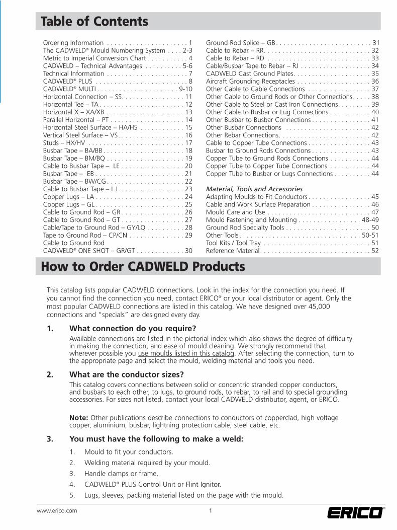
Table of Contents
How to Order CADWELD Products
Ordering Information . . . . . . . . . . . . . . . . . . . . . . 1The CADWELD® Mould Numbering System . . . . 2-3Metric to Imperial Conversion Chart . . . . . . . . . . . 4CADWELD – Technical Advantages . . . . . . . . . . 5-6Technical Information . . . . . . . . . . . . . . . . . . . . . . 7CADWELD® PLUS . . . . . . . . . . . . . . . . . . . . . . . . . 8CADWELD® MULTI . . . . . . . . . . . . . . . . . . . . . . 9-10Horizontal Connection – SS. . . . . . . . . . . . . . . . . 11Horizontal Tee – TA . . . . . . . . . . . . . . . . . . . . . . . 12Horizontal X – XA/XB . . . . . . . . . . . . . . . . . . . . . 13Parallel Horizontal – PT . . . . . . . . . . . . . . . . . . . . 14Horizontal Steel Surface – HA/HS . . . . . . . . . . . . 15Vertical Steel Surface – VS. . . . . . . . . . . . . . . . . . 16Studs – HX/HV . . . . . . . . . . . . . . . . . . . . . . . . . . 17Busbar Tape – BA/BB . . . . . . . . . . . . . . . . . . . . . . 18Busbar Tape – BM/BQ . . . . . . . . . . . . . . . . . . . . . 19Cable to Busbar Tape – LE . . . . . . . . . . . . . . . . . 20Busbar Tape – EB . . . . . . . . . . . . . . . . . . . . . . . . 21Busbar Tape – BW/CG . . . . . . . . . . . . . . . . . . . . . 22Cable to Busbar Tape – L J. . . . . . . . . . . . . . . . . . 23Copper Lugs – LA . . . . . . . . . . . . . . . . . . . . . . . . 24Copper Lugs – GL . . . . . . . . . . . . . . . . . . . . . . . . 25Cable to Ground Rod – GR . . . . . . . . . . . . . . . . . 26Cable to Ground Rod – GT . . . . . . . . . . . . . . . . . 27Cable/Tape to Ground Rod – GY/LQ . . . . . . . . . . 28Tape to Ground Rod – CP/CN . . . . . . . . . . . . . . . 29Cable to Ground Rod CADWELD® ONE SHOT – GR/GT . . . . . . . . . . . . . 30
Ground Rod Splice – GB. . . . . . . . . . . . . . . . . . . . . . . . . . 31Cable to Rebar – RR. . . . . . . . . . . . . . . . . . . . . . . . . . . . . 32Cable to Rebar – RD . . . . . . . . . . . . . . . . . . . . . . . . . . . . 33Cable/Busbar Tape to Rebar – RJ . . . . . . . . . . . . . . . . . . . 34CADWELD Cast Ground Plates. . . . . . . . . . . . . . . . . . . . . 35Aircraft Grounding Receptacles . . . . . . . . . . . . . . . . . . . . 36Other Cable to Cable Connections . . . . . . . . . . . . . . . . . 37Other Cable to Ground Rods or Other Connections. . . . . 38Other Cable to Steel or Cast Iron Connections. . . . . . . . . 39Other Cable to Busbar or Lug Connections . . . . . . . . . . . 40Other Busbar to Busbar Connections . . . . . . . . . . . . . . . . 41Other Busbar Connections . . . . . . . . . . . . . . . . . . . . . . . 42Other Rebar Connections. . . . . . . . . . . . . . . . . . . . . . . . . 42Cable to Copper Tube Connections . . . . . . . . . . . . . . . . . 43Busbar to Ground Rods Connections . . . . . . . . . . . . . . . . 43Copper Tube to Ground Rods Connections . . . . . . . . . . . 44Copper Tube to Copper Tube Connections . . . . . . . . . . . 44Copper Tube to Busbar or Lugs Connections . . . . . . . . . . 44
Material, Tools and AccessoriesAdapting Moulds to Fit Conductors . . . . . . . . . . . . . . . . . 45Cable and Work Surface Preparation . . . . . . . . . . . . . . . . 46Mould Care and Use . . . . . . . . . . . . . . . . . . . . . . . . . . . . 47Mould Fastening and Mounting . . . . . . . . . . . . . . . . . 48-49Ground Rod Specialty Tools . . . . . . . . . . . . . . . . . . . . . . . 50Other Tools . . . . . . . . . . . . . . . . . . . . . . . . . . . . . . . . . 50-51Tool Kits / Tool Tray . . . . . . . . . . . . . . . . . . . . . . . . . . . . . 51Reference Material. . . . . . . . . . . . . . . . . . . . . . . . . . . . . . 52
This catalog lists popular CADWELD connections. Look in the index for the connection you need. Ifyou cannot find the connection you need, contact ERICO® or your local distributor or agent. Only themost popular CADWELD connections are listed in this catalog. We have designed over 45,000connections and “specials” are designed every day.
1. What connection do you require?Available connections are listed in the pictorial index which also shows the degree of difficultyin making the connection, and ease of mould cleaning. We strongly recommend thatwherever possible you use moulds listed in this catalog. After selecting the connection, turn tothe appropriate page and select the mould, welding material and tools you need.
2. What are the conductor sizes?This catalog covers connections between solid or concentric stranded copper conductors, and busbars to each other, to lugs, to ground rods, to rebar, to rail and to special grounding accessories. For sizes not listed, contact your local CADWELD distributor, agent, or ERICO.
Note: Other publications describe connections to conductors of copperclad, high voltage copper, aluminium, busbar, lightning protection cable, steel cable, etc.
3. You must have the following to make a weld:
1. Mould to fit your conductors.
2. Welding material required by your mould.
3. Handle clamps or frame.
4. CADWELD® PLUS Control Unit or Flint Ignitor.
5. Lugs, sleeves, packing material listed on the page with the mould.
1www.erico.com
2 www.erico.com
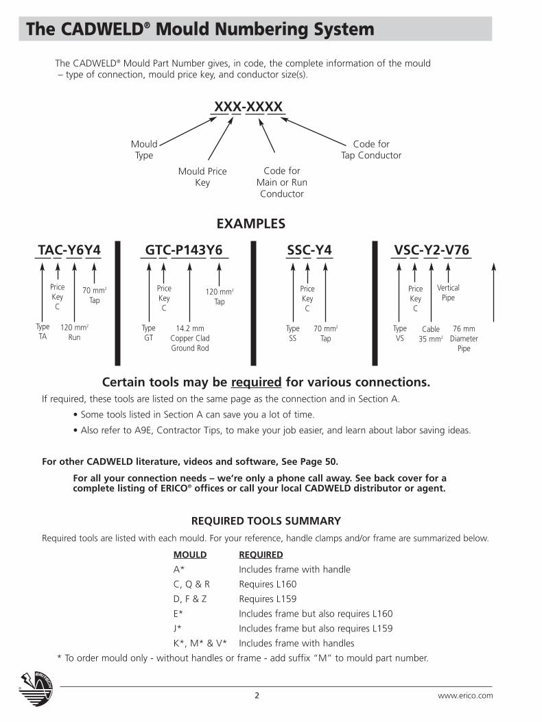
The CADWELD® Mould Numbering System
Code forTap Conductor
The CADWELD® Mould Part Number gives, in code, the complete information of the mould– type of connection, mould price key, and conductor size(s).
XXX-XXXX
TAC-Y6Y4 GTC-P143Y6
EXAMPLES
SSC-Y4 VSC-Y2-V76
MouldType
TypeTA
PriceKeyC
120 mm2
Run
70 mm2
Tap
TypeGT
PriceKeyC
14.2 mmCopper CladGround Rod
120 mm2
Tap
TypeVS
PriceKeyC
VerticalPipe
Cable35 mm2
76 mmDiameter
Pipe
TypeSS
PriceKeyC
70 mm2
Tap
Mould PriceKey
Code forMain or RunConductor
Certain tools may be required for various connections.If required, these tools are listed on the same page as the connection and in Section A.
• Some tools listed in Section A can save you a lot of time.
• Also refer to A9E, Contractor Tips, to make your job easier, and learn about labor saving ideas.
For other CADWELD literature, videos and software, See Page 50.
For all your connection needs – we’re only a phone call away. See back cover for a complete listing of ERICO® offices or call your local CADWELD distributor or agent.
REQUIRED TOOLS SUMMARY
Required tools are listed with each mould. For your reference, handle clamps and/or frame are summarized below.
MOULD REQUIRED
A* Includes frame with handle
C, Q & R Requires L160
D, F & Z Requires L159
E* Includes frame but also requires L160
J* Includes frame but also requires L159
K*, M* & V* Includes frame with handles
* To order mould only - without handles or frame - add suffix “M” to mould part number.
3www.erico.com
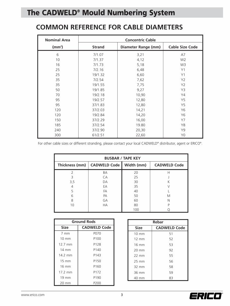
The CADWELD® Mould Numbering System
COMMON REFERENCE FOR CABLE DIAMETERS
Nominal Area Concentric Cable
(mm2) Strand Diameter Range (mm) Cable Size Code
6 7/1.07 3,21 A710 7/1.37 4,12 W216 7/1.73 5,18 W325 7/2.16 6,48 Y125 19/1.32 6,60 Y135 7/2.54 7,62 Y235 19/1.55 7,75 Y250 19/1.85 9,27 Y370 19/2.18 10,90 Y495 19/2.57 12,80 Y595 37/1.83 12,80 Y5
120 37/2.03 14,21 Y6120 19/2.84 14,20 Y6150 37/2.29 16,00 Y7185 37/2.54 19.80 Y8240 37/2.90 20,30 Y9300 61/2.51 22,60 Y0
For other cable sizes or different stranding, please contact your local CADWELD® distributor, agent or ERICO®.
BUSBAR / TAPE KEY
Thickness (mm) CADWELD Code Width (mm) CADWELD Code
2 BA 20 H3 CA 25 J
3,5 DA 30 K4 EA 35 V5 FA 40 L6 PA 50 M8 GA 60 N10 HA 80 P
100 Q
Ground Rods
Size CADWELD Code
7 mm P070
10 mm P100
12.7 mm P128
14 mm P140
14.2 mm P143
15 mm P150
16 mm P160
17.2 mm P172
19 mm P190
20 mm P200
Rebar
Size CADWELD Code
10 mm 51
12 mm 52
16 mm 53
20 mm 92
22 mm 55
25 mm 56
32 mm 58
36 mm 59
40 mm 83
4 www.erico.com
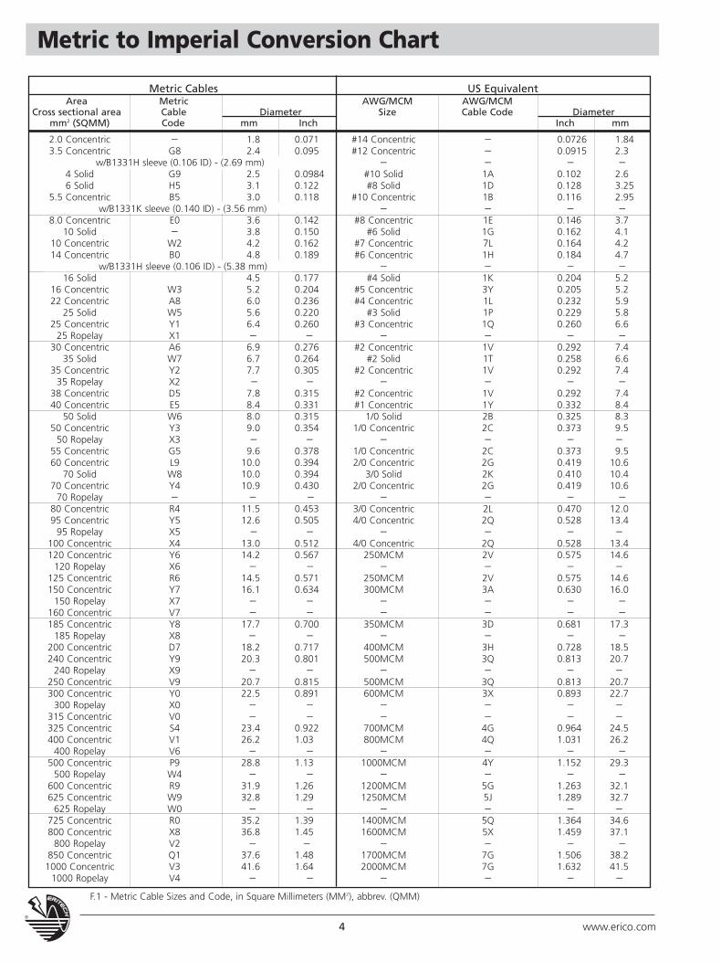
Metric to Imperial Conversion Chart
Metric Cables US EquivalentArea Metric AWG/MCM AWG/MCM
Cross sectional area Cable Diameter Size Cable Code Diametermm2 (SQMM) Code mm Inch Inch mm
2.0 Concentric – 1.8 0.071 #14 Concentric – 0.0726 1.843.5 Concentric G8 2.4 0.095 #12 Concentric – 0.0915 2.3
w/B1331H sleeve (0.106 ID) - (2.69 mm) – – – –4 Solid G9 2.5 0.0984 #10 Solid 1A 0.102 2.66 Solid H5 3.1 0.122 #8 Solid 1D 0.128 3.25
5.5 Concentric B5 3.0 0.118 #10 Concentric 1B 0.116 2.95w/B1331K sleeve (0.140 ID) - (3.56 mm) – – – –
8.0 Concentric E0 3.6 0.142 #8 Concentric 1E 0.146 3.710 Solid – 3.8 0.150 #6 Solid 1G 0.162 4.1
10 Concentric W2 4.2 0.162 #7 Concentric 7L 0.164 4.214 Concentric B0 4.8 0.189 #6 Concentric 1H 0.184 4.7
w/B1331H sleeve (0.106 ID) - (5.38 mm) – – – –16 Solid 4.5 0.177 #4 Solid 1K 0.204 5.2
16 Concentric W3 5.2 0.204 #5 Concentric 3Y 0.205 5.222 Concentric A8 6.0 0.236 #4 Concentric 1L 0.232 5.9
25 Solid W5 5.6 0.220 #3 Solid 1P 0.229 5.825 Concentric Y1 6.4 0.260 #3 Concentric 1Q 0.260 6.6
25 Ropelay X1 – – – – – –30 Concentric A6 6.9 0.276 #2 Concentric 1V 0.292 7.4
35 Solid W7 6.7 0.264 #2 Solid 1T 0.258 6.635 Concentric Y2 7.7 0.305 #2 Concentric 1V 0.292 7.4
35 Ropelay X2 – – – – – –38 Concentric D5 7.8 0.315 #2 Concentric 1V 0.292 7.440 Concentric E5 8.4 0.331 #1 Concentric 1Y 0.332 8.4
50 Solid W6 8.0 0.315 1/0 Solid 2B 0.325 8.350 Concentric Y3 9.0 0.354 1/0 Concentric 2C 0.373 9.5
50 Ropelay X3 – – – – – –55 Concentric G5 9.6 0.378 1/0 Concentric 2C 0.373 9.560 Concentric L9 10.0 0.394 2/0 Concentric 2G 0.419 10.6
70 Solid W8 10.0 0.394 3/0 Solid 2K 0.410 10.470 Concentric Y4 10.9 0.430 2/0 Concentric 2G 0.419 10.6
70 Ropelay – – – – – – –80 Concentric R4 11.5 0.453 3/0 Concentric 2L 0.470 12.095 Concentric Y5 12.6 0.505 4/0 Concentric 2Q 0.528 13.4
95 Ropelay X5 – – – – – –100 Concentric X4 13.0 0.512 4/0 Concentric 2Q 0.528 13.4120 Concentric Y6 14.2 0.567 250MCM 2V 0.575 14.6
120 Ropelay X6 – – – – – –125 Concentric R6 14.5 0.571 250MCM 2V 0.575 14.6150 Concentric Y7 16.1 0.634 300MCM 3A 0.630 16.0
150 Ropelay X7 – – – – – –160 Concentric V7 – – – – – –185 Concentric Y8 17.7 0.700 350MCM 3D 0.681 17.3
185 Ropelay X8 – – – – – –200 Concentric D7 18.2 0.717 400MCM 3H 0.728 18.5240 Concentric Y9 20.3 0.801 500MCM 3Q 0.813 20.7
240 Ropelay X9 – – – – – –250 Concentric V9 20.7 0.815 500MCM 3Q 0.813 20.7300 Concentric Y0 22.5 0.891 600MCM 3X 0.893 22.7
300 Ropelay X0 – – – – – –315 Concentric V0 – – – – – –325 Concentric S4 23.4 0.922 700MCM 4G 0.964 24.5400 Concentric V1 26.2 1.03 800MCM 4Q 1.031 26.2
400 Ropelay V6 – – – – – –500 Concentric P9 28.8 1.13 1000MCM 4Y 1.152 29.3
500 Ropelay W4 – – – – – –600 Concentric R9 31.9 1.26 1200MCM 5G 1.263 32.1625 Concentric W9 32.8 1.29 1250MCM 5J 1.289 32.7
625 Ropelay W0 – – – – – –725 Concentric R0 35.2 1.39 1400MCM 5Q 1.364 34.6800 Concentric X8 36.8 1.45 1600MCM 5X 1.459 37.1
800 Ropelay V2 – – – – – –850 Concentric Q1 37.6 1.48 1700MCM 7G 1.506 38.21000 Concentric V3 41.6 1.64 2000MCM 7G 1.632 41.5
1000 Ropelay V4 – – – – – –
F.1 - Metric Cable Sizes and Code, in Square Millimeters (MM2), abbrev. (QMM)
5www.erico.com
CADWELD® - Technical AdvantagesTHE CADWELD® WELD
• Has a current-carrying capacity equal to thatof the conductor
• Creates a permanent bond that withstandsrepeated fault currents and will not loosen,deteriorate or increase in resistance
• Consistently performs the best in independent IEEE® 837 tests
• Is easy to check visibly for quality
RELIABILITY
As the molecular bond eliminates the conceptof surface contact, an electrolyte cannot penetratebetween the conductors and cause oxidation anddeterioration in the course of time.
CORROSIVE ENVIRONMENTS
This reliability is of particular interest for humidor chemical environments or for bonds directlyburied in the ground.
ABILITY TO WITHSTAND HIGH CURRENT
The melting temperature of CADWELD connection is higher than the melting temperatureof copper (1082°C). For this reason, in theevent of abnormal heating due to a high fault current, the conductor is destroyed before theconnection.
CONDUCTIVITY
The CADWELD connections form a solid bondaround the conductors assuring continuity. Thecross sectional area of the weld has greater current carrying capacity than the conductors.
PERFORMANCE
Standard CADWELD welds have a crosssection greater than that of the conductorsto be joined, which compensates for thedifference in resistivity between theconductor and the welding material.Consequently, under fault conditions theweld will always remain cooler than theconductor.If special applications do not allow for therequired increase in cross section to beemployed, the use of the formula: R = p x l and V= R x l
Swill make it possible to define precisely theresistance of the CADWELD® weld.
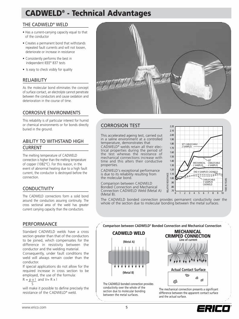
CORROSION TEST
This accelerated ageing test, carried outin a saline environment at a controlledtemperature, demonstrates that CADWELD® welds retain all their elec-trical properties during the period ofthe test whereas the resistance ofmechanical connections increase withtime and this alters their conductiveproperties.
CADWELD's exceptional performanceis due to its reliability resulting fromthe molecular bond.
Comparison between CADWELDBonded Connection and MechanicalConnection CADWELD Weld (Metal A)(Metal B).The CADWELD bonded connection provides permanent conductivity over thewhole of the section due to molecular bonding between the metal surfaces.
SET CABLE/CABLE2 SAMPLES
MECHANICAL2 SAMPLES
SET CABLE/CABLE4 SAMPLES
CABLE/CABLE3 SAMPLESCADWELD
END 4 SAMPLES CADWELD
RELA
TIVE
RES
ISTA
NCE
TIM
E IN
YEA
RSComparison between CADWELD® Bonded Connection and Mechanical Connection
CADWELD WELD MECHANICAL CRIMPED CONNECTION
Line of current(Metal A)
(Metal B)Actual Contact Surface
The CADWELD bonded connection providesconductivity over the whole of the section due to molecular bonding between the metal surfaces.
The mechanical connection presents a significantdifference between the apparent contact surfaceand the actual surface.
6 www.erico.com
CADWELD® - Technical Advantages
The grounding conductor size is based on themaximum magnitude and duration of availablefault current, and on the type of connectionsbeing used in the grounding system.
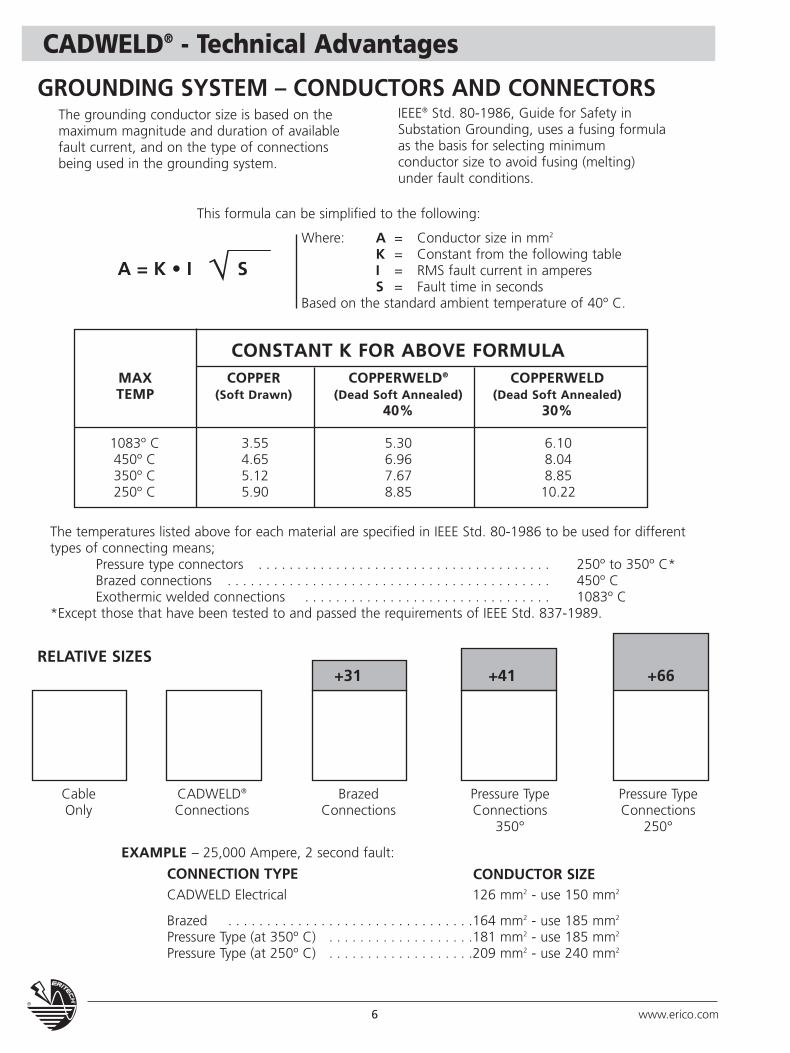
GROUNDING SYSTEM – CONDUCTORS AND CONNECTORS
This formula can be simplified to the following:
CONSTANT K FOR ABOVE FORMULAMAX COPPER COPPERWELD® COPPERWELDTEMP (Soft Drawn) (Dead Soft Annealed) (Dead Soft Annealed)
40% 30%
1083º C 3.55 5.30 6.10450º C 4.65 6.96 8.04350º C 5.12 7.67 8.85250º C 5.90 8.85 10.22
The temperatures listed above for each material are specified in IEEE Std. 80-1986 to be used for differenttypes of connecting means;
Pressure type connectors . . . . . . . . . . . . . . . . . . . . . . . . . . . . . . . . . . . . . . 250º to 350º C*Brazed connections . . . . . . . . . . . . . . . . . . . . . . . . . . . . . . . . . . . . . . . . . . 450º CExothermic welded connections . . . . . . . . . . . . . . . . . . . . . . . . . . . . . . . . 1083º C
*Except those that have been tested to and passed the requirements of IEEE Std. 837-1989.
RELATIVE SIZES+31 +41 +66
CableOnly
CADWELD®
ConnectionsBrazed
ConnectionsPressure TypeConnections
350°
Pressure TypeConnections
250°
EXAMPLE – 25,000 Ampere, 2 second fault:
CADWELD Electrical 126 mm2 - use 150 mm2
Brazed . . . . . . . . . . . . . . . . . . . . . . . . . . . . . . . .164 mm2 - use 185 mm2
Pressure Type (at 350º C) . . . . . . . . . . . . . . . . . . .181 mm2 - use 185 mm2
Pressure Type (at 250º C) . . . . . . . . . . . . . . . . . . .209 mm2 - use 240 mm2
IEEE® Std. 80-1986, Guide for Safety inSubstation Grounding, uses a fusing formulaas the basis for selecting minimumconductor size to avoid fusing (melting)under fault conditions.
Where: A = Conductor size in mm2
K = Constant from the following tableA = K • I S I = RMS fault current in amperes
S = Fault time in secondsBased on the standard ambient temperature of 40º C.
CONNECTION TYPE CONDUCTOR SIZE
Technical Information
CADWELD®
THE MOLECULAR BONDCADWELD® EXOTHERMIC CONNECTIONA welding process that eliminates the connection by forming a molecular bond.Connections are the weak point of all electrical circuits and especiallyearthing circuits subjected to aging and corrosion. The capacity of anearthing circuit to protect the safety of personnel depends on the quality ofthe connections made.
BS 6651 (1992) STATES :
"Any joint other than welded represents a discontinuity in the currentconducting system and is susceptible to variation and failure.”
CADWELD® – TheMolecular BondThe CADWELD® process provides a way to produce copper/copper, copper/galvanized or plain steel, copper/copper clad steel, cop-per/bronze/brass/stainless steel, steel/steel, molecular bonds with noexternal energy or heat source.
The principle consists of bringing together a welding materials andignition agent in a suitable graphite mould.
The reduction of copper oxide by aluminium produces molten copperand aluminium oxide slag at extremely high temperatures.
The shape of the mould, its dimensions, and the size of the welding material, are all dependent on the items to be welded.
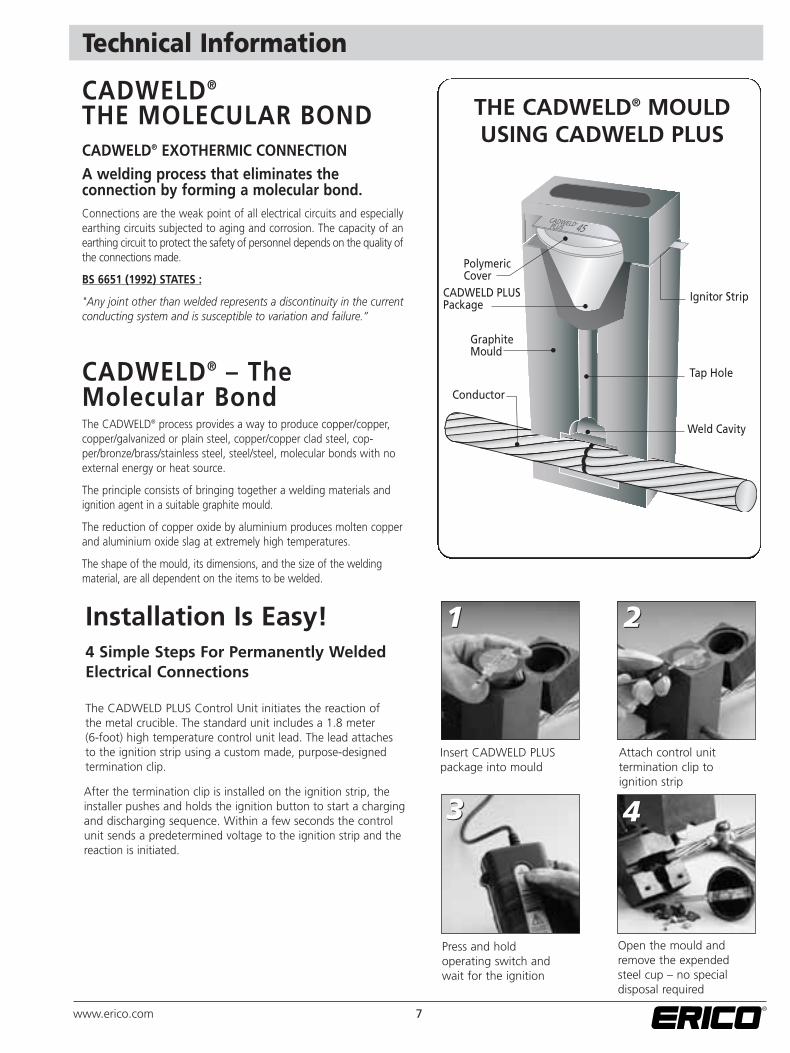
THE CADWELD® MOULDUSING CADWELD PLUS
Installation Is Easy! 4 Simple Steps For Permanently WeldedElectrical Connections
11 22
33 44
Insert CADWELD PLUS package into mould
Press and hold operating switch andwait for the ignition
Attach control unit termination clip to ignition strip
Open the mould andremove the expendedsteel cup – no specialdisposal required
The CADWELD PLUS Control Unit initiates the reaction of the metal crucible. The standard unit includes a 1.8 meter (6-foot) high temperature control unit lead. The lead attaches to the ignition strip using a custom made, purpose-designed termination clip.
After the termination clip is installed on the ignition strip, theinstaller pushes and holds the ignition button to start a chargingand discharging sequence. Within a few seconds the controlunit sends a predetermined voltage to the ignition strip and thereaction is initiated.
7www.erico.com
8 www.erico.com
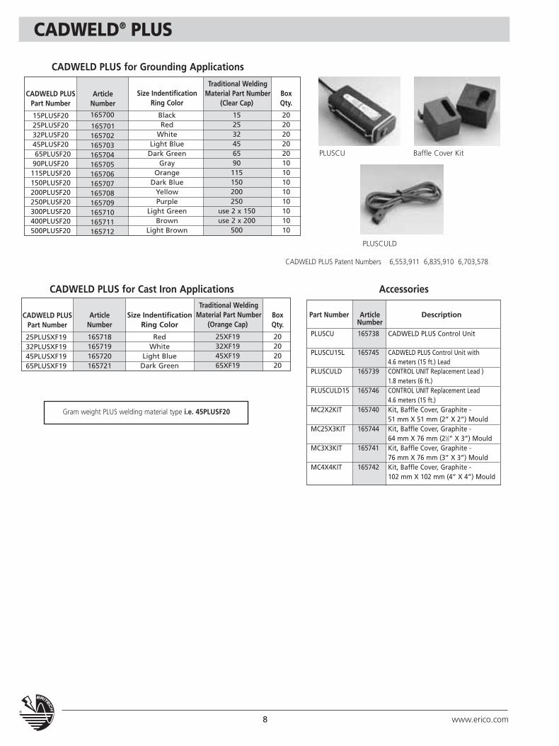
CADWELD® PLUS
Article Number
165700
165701165702165703165704165705165706165707165708165709165710165711165712
Size IndentificationRing Color
BlackRed
WhiteLight Blue
Dark GreenGray
OrangeDark Blue
YellowPurple
Light GreenBrown
Light Brown
Traditional Welding Material Part Number
(Clear Cap)
152532456590115150200250
use 2 x 150use 2 x 200
500
BoxQty.
20202020201010101010101010
BoxQty.
20202020
CADWELD PLUSPart Number
15PLUSF2025PLUSF2032PLUSF2045PLUSF2065PLUSF20
90PLUSF20115PLUSF20150PLUSF20200PLUSF20250PLUSF20300PLUSF20400PLUSF20500PLUSF20
CADWELD PLUS for Grounding Applications
Traditional Welding Material Part Number
(Orange Cap)
25XF1932XF1945XF1965XF19
Article Number
165718165719165720165721
CADWELD PLUSPart Number
25PLUSXF1932PLUSXF1945PLUSXF1965PLUSXF19
CADWELD PLUS for Cast Iron Applications Accessories
PLUSCU Baffle Cover Kit
PLUSCULD
Gram weight PLUS welding material type i.e. 45PLUSF20
CADWELD PLUS Patent Numbers 6,553,911 6,835,910 6,703,578
Part Number Article DescriptionNumber
PLUSCU 165738 CADWELD PLUS Control Unit
PLUSCU15L 165745 CADWELD PLUS Control Unit with 4.6 meters (15 ft.) Lead
PLUSCULD 165739 CONTROL UNIT Replacement Lead )1.8 meters (6 ft.)
PLUSCULD15 165746 CONTROL UNIT Replacement Lead 4.6 meters (15 ft.)
MC2X2KIT 165740 Kit, Baffle Cover, Graphite - 51 mm X 51 mm (2” X 2”) Mould
MC25X3KIT 165744 Kit, Baffle Cover, Graphite - 64 mm X 76 mm (21⁄2” X 3”) Mould
MC3X3KIT 165741 Kit, Baffle Cover, Graphite - 76 mm X 76 mm (3” X 3”) Mould
MC4X4KIT 165742 Kit, Baffle Cover, Graphite - 102 mm X 102 mm (4” X 4”) Mould
Size IndentificationRing Color
RedWhite
Light BlueDark Green
9www.erico.com
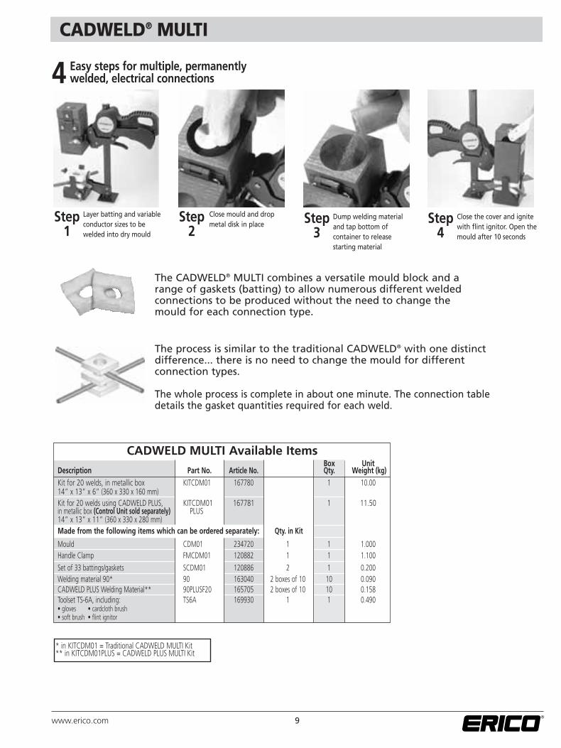
CADWELD® MULTI
CADWELD MULTI Available Items
Easy steps for multiple, permanentlywelded, electrical connections
Step1
Layer batting and variableconductor sizes to be welded into dry mould
Dump welding material and tap bottom of container to release starting material
Close the cover and ignitewith flint ignitor. Open themould after 10 seconds
Close mould and dropmetal disk in place
Step2
Step4
Step3
4
The CADWELD® MULTI combines a versatile mould block and arange of gaskets (batting) to allow numerous different welded connections to be produced without the need to change themould for each connection type.
The process is similar to the traditional CADWELD® with one distinct difference... there is no need to change the mould for different connection types.
The whole process is complete in about one minute. The connection tabledetails the gasket quantities required for each weld.
* in KITCDM01 = Traditional CADWELD MULTI Kit** in KITCDM01PLUS = CADWELD PLUS MULTI Kit
Box UnitDescription Part No. Article No. Qty. Weight (kg)Kit for 20 welds, in metallic box KITCDM01 167780 1 10.0014” x 13” x 6” (360 x 330 x 160 mm)Kit for 20 welds using CADWELD PLUS, KITCDM01 167781 1 11.50in metallic box (Control Unit sold separately) PLUS14” x 13” x 11” (360 x 330 x 280 mm)Made from the following items which can be ordered separately: Qty. in Kit
Mould CDM01 234720 1 1 1.000Handle Clamp FMCDM01 120882 1 1 1.100Set of 33 battings/gaskets SCDM01 120886 2 1 0.200Welding material 90* 90 163040 2 boxes of 10 10 0.090CADWELD PLUS Welding Material** 90PLUSF20 165705 2 boxes of 10 10 0.158Toolset TS-6A, including: TS6A 169930 1 1 0.490• gloves • cardcloth brush• soft brush • flint ignitor
10 www.erico.com
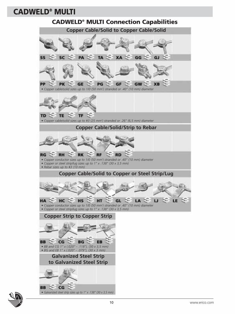
CADWELD® MULTICADWELD® MULTI Connection Capabilities
Copper Cable/Solid to Copper Cable/Solid
• Copper cable/solid sizes up to 1/0 (50 mm2) stranded or .40” (10 mm) diameter
• Copper cable/solid sizes up to #3 (25 mm2) stranded or .26” (6,5 mm) diameter
• Copper conductor sizes up to 1/0 (50 mm2) stranded or .40” (10 mm) diameter• Copper or steel strip/lug sizes up to 1” x .138” (30 x 3,5 mm)• Rebar sizes up to #3 (10 mm)
• Copper conductor sizes up to 1/0 (50 mm2) stranded or .40” (10 mm) diameter• Copper or steel strip/lug sizes up to 1” x .138” (30 x 3,5 mm)
• BB and CG 1” x (.020” - .118”), (30 x 3,5 mm)• BG and EB 1” x (.020” - .079”), (30 x 3 mm)
• Galvanized steel strip sizes up to 1” x .138” (30 x 3,5 mm)
Copper Cable/Solid/Strip to Rebar
Copper Strip to Copper Strip
Galvanized Steel Stripto Galvanized Steel Strip
Copper Cable/Solid to Copper or Steel Strip/Lug
11www.erico.com
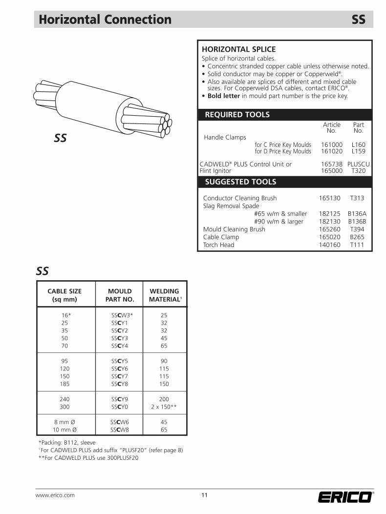
Horizontal Connection SS
SUGGESTED TOOLS
REQUIRED TOOLS
CABLE SIZE MOULD WELDING(sq mm) PART NO. MATERIAL1
16* SSCW3* 2525 SSCY1 3235 SSCY2 3250 SSCY3 4570 SSCY4 65
95 SSCY5 90120 SSCY6 115150 SSCY7 115185 SSCY8 150
240 SSCY9 200300 SSCY0 2 x 150**
8 mm Ø SSCW6 4510 mm Ø SSCW8 65
*Packing: B112, sleeve1 For CADWELD PLUS add suffix “PLUSF20” (refer page 8)**For CADWELD PLUS use 300PLUSF20
HORIZONTAL SPLICESplice of horizontal cables.• Concentric stranded copper cable unless otherwise noted.• Solid conductor may be copper or Copperweld®.• Also available are splices of different and mixed cable
sizes. For Copperweld DSA cables, contact ERICO®.• Bold letter in mould part number is the price key.
SS
SS
Article PartNo. No.
Handle Clamps for C Price Key Moulds 161000 L160for D Price Key Moulds 161020 L159
CADWELD® PLUS Control Unit or 165738 PLUSCUFlint Ignitor 165000 T320
Conductor Cleaning Brush 165130 T313Slag Removal Spade
#65 w/m & smaller 182125 B136A#90 w/m & larger 182130 B136B
Mould Cleaning Brush 165260 T394Cable Clamp 165020 B265Torch Head 140160 T111
12 www.erico.com
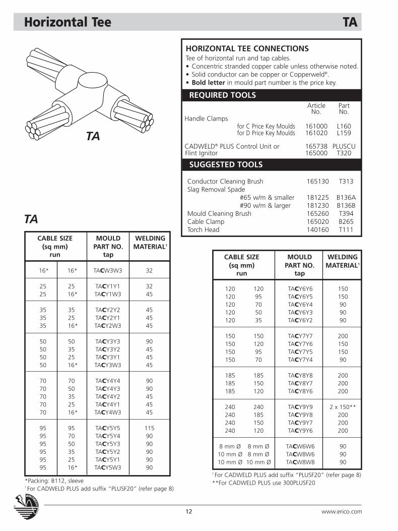
Horizontal Tee TA
TA
CABLE SIZE MOULD WELDING(sq mm) PART NO. MATERIAL1
run tap
HORIZONTAL TEE CONNECTIONS Tee of horizontal run and tap cables.• Concentric stranded copper cable unless otherwise noted.• Solid conductor can be copper or Copperweld®.• Bold letter in mould part number is the price key.
CABLE SIZE MOULD WELDING(sq mm) PART NO. MATERIAL1
run tap
16* 16* TACW3W3 32
25 25 TACY1Y1 3225 16* TACY1W3 45
35 35 TACY2Y2 4535 25 TACY2Y1 4535 16* TACY2W3 45
50 50 TACY3Y3 9050 35 TACY3Y2 4550 25 TACY3Y1 4550 16* TACY3W3 45
70 70 TACY4Y4 9070 50 TACY4Y3 9070 35 TACY4Y2 4570 25 TACY4Y1 4570 16* TACY4W3 45
95 95 TACY5Y5 11595 70 TACY5Y4 9095 50 TACY5Y3 9095 35 TACY5Y2 9095 25 TACY5Y1 9095 16* TACY5W3 90
120 120 TACY6Y6 150120 95 TACY6Y5 150120 70 TACY6Y4 90120 50 TACY6Y3 90120 35 TACY6Y2 90
150 150 TACY7Y7 200150 120 TACY7Y6 150150 95 TACY7Y5 150150 70 TACY7Y4 90
185 185 TACY8Y8 200185 150 TACY8Y7 200185 120 TACY8Y6 200
240 240 TACY9Y9 2 x 150**240 185 TACY9Y8 200240 150 TACY9Y7 200240 120 TACY9Y6 200
8 mm Ø 8 mm Ø TACW6W6 9010 mm Ø 8 mm Ø TACW8W6 9010 mm Ø 10 mm Ø TACW8W8 90
TA
SUGGESTED TOOLS
REQUIRED TOOLSArticle Part
No. No.Handle Clamps
for C Price Key Moulds 161000 L160for D Price Key Moulds 161020 L159
CADWELD® PLUS Control Unit or 165738 PLUSCUFlint Ignitor 165000 T320
Conductor Cleaning Brush 165130 T313Slag Removal Spade
#65 w/m & smaller 181225 B136A#90 w/m & larger 181230 B136B
Mould Cleaning Brush 165260 T394Cable Clamp 165020 B265Torch Head 140160 T111
*Packing: B112, sleeve1 For CADWELD PLUS add suffix “PLUSF20” (refer page 8)
1 For CADWELD PLUS add suffix “PLUSF20” (refer page 8)**For CADWELD PLUS use 300PLUSF20
13www.erico.com
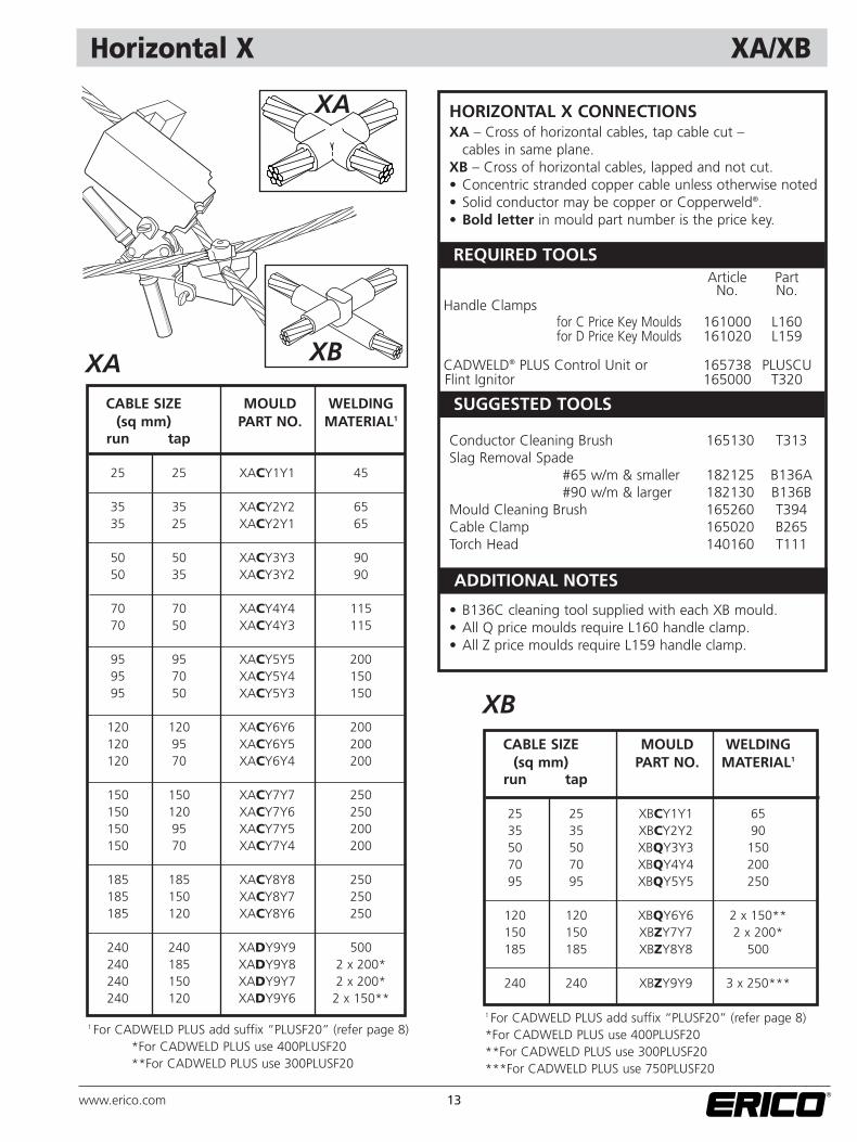
Horizontal X XA/XB
HORIZONTAL X CONNECTIONSXA – Cross of horizontal cables, tap cable cut –
cables in same plane.XB – Cross of horizontal cables, lapped and not cut.• Concentric stranded copper cable unless otherwise noted• Solid conductor may be copper or Copperweld®.• Bold letter in mould part number is the price key.
• B136C cleaning tool supplied with each XB mould.• All Q price moulds require L160 handle clamp.• All Z price moulds require L159 handle clamp.
XACABLE SIZE MOULD WELDING
(sq mm) PART NO. MATERIAL1
run tap
25 25 XACY1Y1 45
35 35 XACY2Y2 6535 25 XACY2Y1 65
50 50 XACY3Y3 9050 35 XACY3Y2 90
70 70 XACY4Y4 11570 50 XACY4Y3 115
95 95 XACY5Y5 20095 70 XACY5Y4 15095 50 XACY5Y3 150
120 120 XACY6Y6 200120 95 XACY6Y5 200120 70 XACY6Y4 200
150 150 XACY7Y7 250150 120 XACY7Y6 250150 95 XACY7Y5 200150 70 XACY7Y4 200
185 185 XACY8Y8 250185 150 XACY8Y7 250185 120 XACY8Y6 250
240 240 XADY9Y9 500240 185 XADY9Y8 2 x 200*240 150 XADY9Y7 2 x 200*240 120 XADY9Y6 2 x 150**
XBCABLE SIZE MOULD WELDING
(sq mm) PART NO. MATERIAL1
run tap
25 25 XBCY1Y1 6535 35 XBCY2Y2 9050 50 XBQY3Y3 15070 70 XBQY4Y4 20095 95 XBQY5Y5 250
120 120 XBQY6Y6 2 x 150**150 150 XBZY7Y7 2 x 200*185 185 XBZY8Y8 500
240 240 XBZY9Y9 3 x 250***
ADDITIONAL NOTES
XB
XA
SUGGESTED TOOLS
REQUIRED TOOLSArticle Part
No. No.Handle Clamps
for C Price Key Moulds 161000 L160for D Price Key Moulds 161020 L159
CADWELD® PLUS Control Unit or 165738 PLUSCUFlint Ignitor 165000 T320
Conductor Cleaning Brush 165130 T313Slag Removal Spade
#65 w/m & smaller 182125 B136A#90 w/m & larger 182130 B136B
Mould Cleaning Brush 165260 T394Cable Clamp 165020 B265Torch Head 140160 T111
1 For CADWELD PLUS add suffix “PLUSF20” (refer page 8)*For CADWELD PLUS use 400PLUSF20**For CADWELD PLUS use 300PLUSF20
1 For CADWELD PLUS add suffix “PLUSF20” (refer page 8)*For CADWELD PLUS use 400PLUSF20**For CADWELD PLUS use 300PLUSF20***For CADWELD PLUS use 750PLUSF20
14 www.erico.com
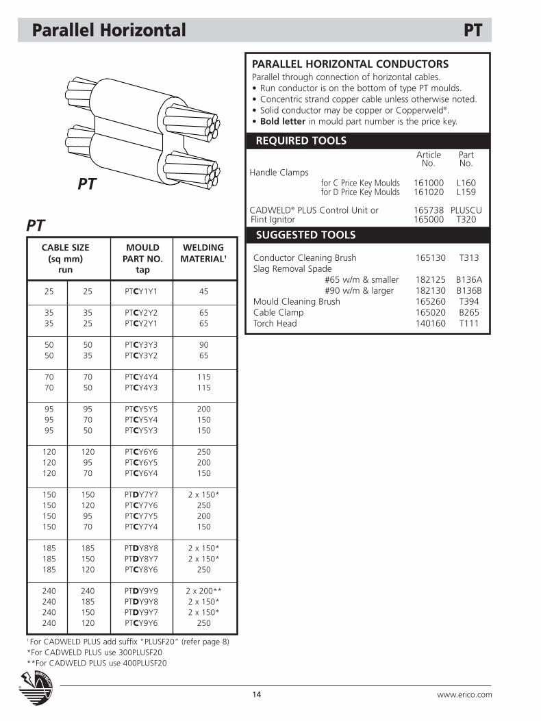
Parallel Horizontal PT
CABLE SIZE MOULD WELDING(sq mm) PART NO. MATERIAL1
run tap
25 25 PTCY1Y1 45
35 35 PTCY2Y2 6535 25 PTCY2Y1 65
50 50 PTCY3Y3 9050 35 PTCY3Y2 65
70 70 PTCY4Y4 11570 50 PTCY4Y3 115
95 95 PTCY5Y5 20095 70 PTCY5Y4 15095 50 PTCY5Y3 150
120 120 PTCY6Y6 250120 95 PTCY6Y5 200120 70 PTCY6Y4 150
150 150 PTDY7Y7 2 x 150*150 120 PTCY7Y6 250150 95 PTCY7Y5 200150 70 PTCY7Y4 150
185 185 PTDY8Y8 2 x 150*185 150 PTDY8Y7 2 x 150*185 120 PTCY8Y6 250
240 240 PTDY9Y9 2 x 200**240 185 PTDY9Y8 2 x 150*240 150 PTDY9Y7 2 x 150*240 120 PTCY9Y6 250
PARALLEL HORIZONTAL CONDUCTORSParallel through connection of horizontal cables.• Run conductor is on the bottom of type PT moulds.• Concentric strand copper cable unless otherwise noted.• Solid conductor may be copper or Copperweld®.• Bold letter in mould part number is the price key.
PT
PTSUGGESTED TOOLS
REQUIRED TOOLSArticle Part
No. No.Handle Clamps
for C Price Key Moulds 161000 L160for D Price Key Moulds 161020 L159
CADWELD® PLUS Control Unit or 165738 PLUSCUFlint Ignitor 165000 T320
Conductor Cleaning Brush 165130 T313Slag Removal Spade
#65 w/m & smaller 182125 B136A#90 w/m & larger 182130 B136B
Mould Cleaning Brush 165260 T394Cable Clamp 165020 B265Torch Head 140160 T111
1 For CADWELD PLUS add suffix “PLUSF20” (refer page 8)*For CADWELD PLUS use 300PLUSF20**For CADWELD PLUS use 400PLUSF20
15www.erico.com
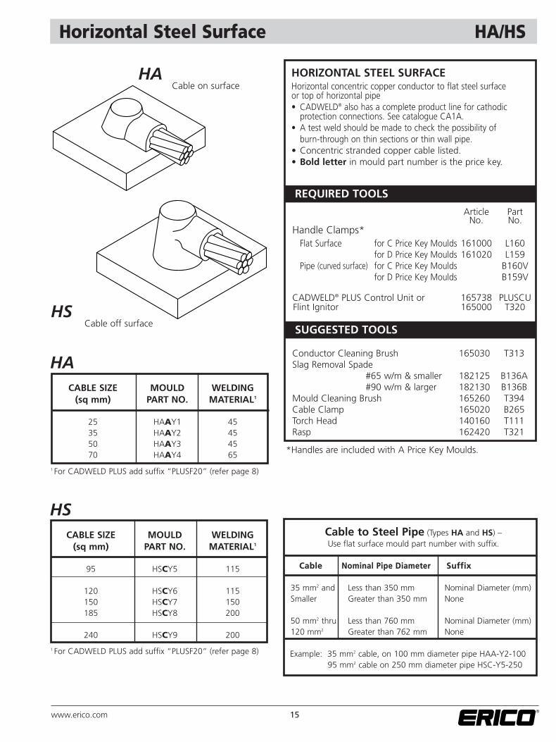
Horizontal Steel Surface HA/HS
HSCable off surface
HACABLE SIZE MOULD WELDING
(sq mm) PART NO. MATERIAL1
25 HAAY1 4535 HAAY2 4550 HAAY3 4570 HAAY4 65
HSCABLE SIZE MOULD WELDING
(sq mm) PART NO. MATERIAL1
95 HSCY5 115
120 HSCY6 115150 HSCY7 150185 HSCY8 200
240 HSCY9 200
Cable to Steel Pipe (Types HA and HS) –Use flat surface mould part number with suffix.
Cable Nominal Pipe Diameter Suffix
35 mm2 and Less than 350 mm Nominal Diameter (mm)Smaller Greater than 350 mm None
50 mm2 thru Less than 760 mm Nominal Diameter (mm)120 mm2 Greater than 762 mm None
Example: 35 mm2 cable, on 100 mm diameter pipe HAA-Y2-100 95 mm2 cable on 250 mm diameter pipe HSC-Y5-250
HACable on surface
HORIZONTAL STEEL SURFACEHorizontal concentric copper conductor to flat steel surface or top of horizontal pipe• CADWELD® also has a complete product line for cathodic
protection connections. See catalogue CA1A.• A test weld should be made to check the possibility of
burn-through on thin sections or thin wall pipe.• Concentric stranded copper cable listed.• Bold letter in mould part number is the price key.
SUGGESTED TOOLS
REQUIRED TOOLS
Article PartNo. No.
Handle Clamps*Flat Surface for C Price Key Moulds 161000 L160
for D Price Key Moulds 161020 L159Pipe (curved surface) for C Price Key Moulds B160V
for D Price Key Moulds B159V
CADWELD® PLUS Control Unit or 165738 PLUSCUFlint Ignitor 165000 T320
Conductor Cleaning Brush 165030 T313Slag Removal Spade
#65 w/m & smaller 182125 B136A#90 w/m & larger 182130 B136B
Mould Cleaning Brush 165260 T394Cable Clamp 165020 B265Torch Head 140160 T111Rasp 162420 T321
*Handles are included with A Price Key Moulds.
1 For CADWELD PLUS add suffix “PLUSF20” (refer page 8)
1 For CADWELD PLUS add suffix “PLUSF20” (refer page 8)
16 www.erico.com
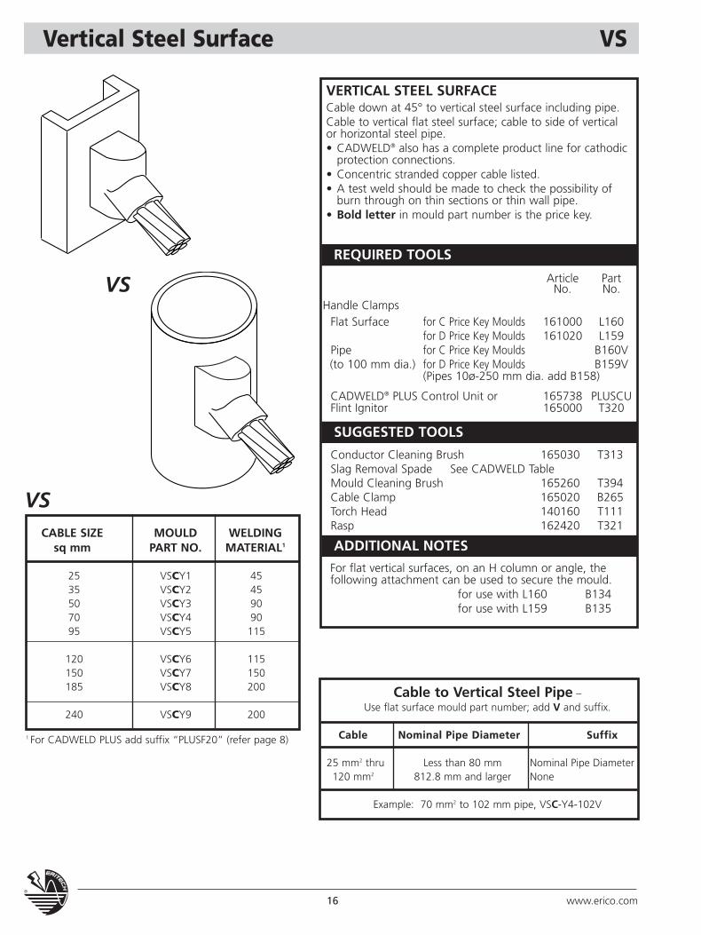
Vertical Steel Surface VS
VSCABLE SIZE MOULD WELDING
sq mm PART NO. MATERIAL1
25 VSCY1 4535 VSCY2 4550 VSCY3 9070 VSCY4 9095 VSCY5 115
120 VSCY6 115150 VSCY7 150185 VSCY8 200
240 VSCY9 200
VS
VERTICAL STEEL SURFACECable down at 45° to vertical steel surface including pipe.Cable to vertical flat steel surface; cable to side of vertical or horizontal steel pipe.• CADWELD® also has a complete product line for cathodic
protection connections.• Concentric stranded copper cable listed.• A test weld should be made to check the possibility of
burn through on thin sections or thin wall pipe.• Bold letter in mould part number is the price key.
Cable to Vertical Steel Pipe –Use flat surface mould part number; add V and suffix.
Cable Nominal Pipe Diameter Suffix
25 mm2 thru Less than 80 mm Nominal Pipe Diameter120 mm2 812.8 mm and larger None
Example: 70 mm2 to 102 mm pipe, VSC-Y4-102V
SUGGESTED TOOLS
ADDITIONAL NOTES
REQUIRED TOOLS
Article PartNo. No.
Handle Clamps Flat Surface for C Price Key Moulds 161000 L160
for D Price Key Moulds 161020 L159Pipe for C Price Key Moulds B160V(to 100 mm dia.) for D Price Key Moulds B159V
(Pipes 10ø-250 mm dia. add B158)
CADWELD® PLUS Control Unit or 165738 PLUSCUFlint Ignitor 165000 T320
Conductor Cleaning Brush 165030 T313Slag Removal Spade See CADWELD TableMould Cleaning Brush 165260 T394Cable Clamp 165020 B265Torch Head 140160 T111Rasp 162420 T321
For flat vertical surfaces, on an H column or angle, the following attachment can be used to secure the mould.
for use with L160 B134for use with L159 B135
1 For CADWELD PLUS add suffix “PLUSF20” (refer page 8)
17www.erico.com
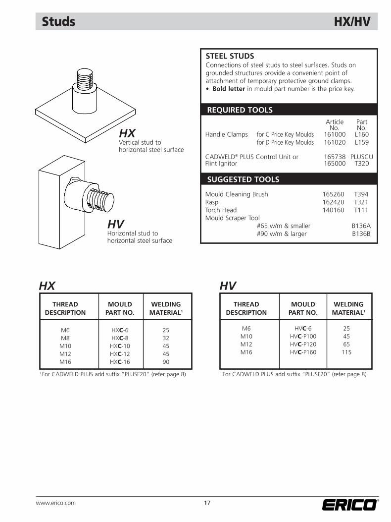
Studs HX/HV
SUGGESTED TOOLS
REQUIRED TOOLS
STEEL STUDSConnections of steel studs to steel surfaces. Studs ongrounded structures provide a convenient point of attachment of temporary protective ground clamps.• Bold letter in mould part number is the price key.
Article PartNo. No.
Handle Clamps for C Price Key Moulds 161000 L160for D Price Key Moulds 161020 L159
CADWELD® PLUS Control Unit or 165738 PLUSCUFlint Ignitor 165000 T320
Mould Cleaning Brush 165260 T394Rasp 162420 T321Torch Head 140160 T111Mould Scraper Tool
#65 w/m & smaller B136A#90 w/m & larger B136B
HXTHREAD MOULD WELDING
DESCRIPTION PART NO. MATERIAL1
M6 HXC-6 25M8 HXC-8 32M10 HXC-10 45M12 HXC-12 45M16 HXC-16 90
HVTHREAD MOULD WELDING
DESCRIPTION PART NO. MATERIAL1
M6 HVC-6 25M10 HVC-P100 45M12 HVC-P120 65M16 HVC-P160 115
HXVertical stud to horizontal steel surface
HVHorizontal stud to horizontal steel surface
1 For CADWELD PLUS add suffix “PLUSF20” (refer page 8) 1 For CADWELD PLUS add suffix “PLUSF20” (refer page 8)

18 www.erico.com
Busbar Tape BA/BB
BBBUSBAR MOULD WELDING
SIZE PART NO. MATERIAL1
3X25 BBCCAJ 903X50 BBRCAM 150
4X40 BBCEAL 1504X50 BBREAM 150
5X40 BBCFAL 1505X50 BBRFAM 200
6X25 BBCPAJ 1156X50 BBRPAM 250
BABUSBAR MOULD WELDING
SIZE PART NO. MATERIAL1
3X25 BACCAJ 653X50 BACCAM 90
4X40 BACEAL 1154X50 BACEAM 115
5X40 BACFAL 1505X50 BACFAM 200
6X25 BACPAJ 1156X50 BACPAM 150
COPPER BUSBAR SPLICETYPE BA – Horizontal, on-edge, busbar.TYPE BB – Horizontal busbars.• Bold letter in mould part number is the price key.
BA
BB
SUGGESTED TOOLS
REQUIRED TOOLSArticle Part
No. No.Handle Clamps
for C Price Key Moulds 161000 L160for D Price Key Moulds 161020 L159
CADWELD® PLUS Control Unit or 165738 PLUSCUFlint Ignitor 165000 T320
Conductor Cleaning Brush 165130 T313Slag Removal Spade
#65 w/m & smaller 182125 B136A#90 w/m & larger 182130 B136B
Mould Cleaning Brush 165260 T394Cable Clamp 165020 B265Torch Head 140160 T111
1 For CADWELD PLUS add suffix “PLUSF20” (refer page 8) 1 For CADWELD PLUS add suffix “PLUSF20” (refer page 8)
19www.erico.com
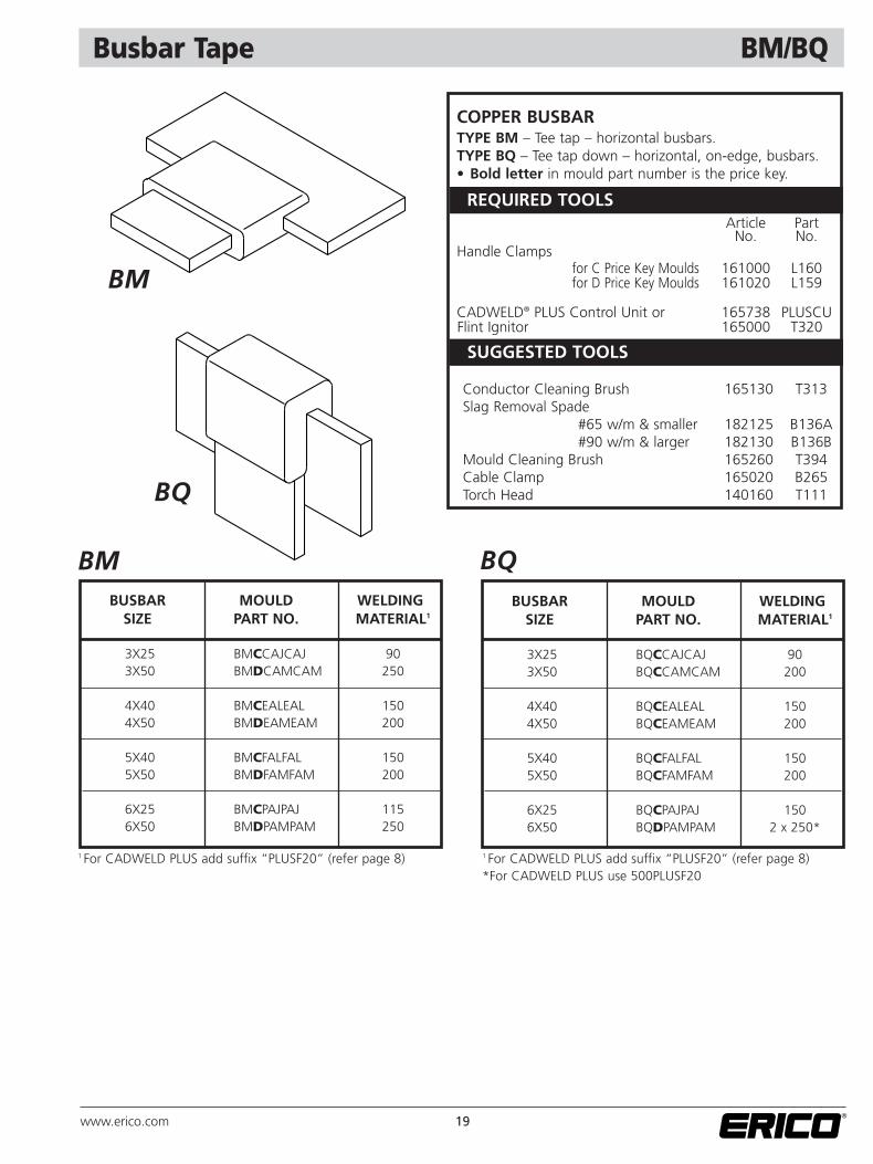
Busbar Tape BM/BQ
BMBUSBAR MOULD WELDING
SIZE PART NO. MATERIAL1
3X25 BMCCAJCAJ 903X50 BMDCAMCAM 250
4X40 BMCEALEAL 1504X50 BMDEAMEAM 200
5X40 BMCFALFAL 1505X50 BMDFAMFAM 200
6X25 BMCPAJPAJ 1156X50 BMDPAMPAM 250
BQBUSBAR MOULD WELDING
SIZE PART NO. MATERIAL1
3X25 BQCCAJCAJ 903X50 BQCCAMCAM 200
4X40 BQCEALEAL 1504X50 BQCEAMEAM 200
5X40 BQCFALFAL 1505X50 BQCFAMFAM 200
6X25 BQCPAJPAJ 1506X50 BQDPAMPAM 2 x 250*
COPPER BUSBARTYPE BM – Tee tap – horizontal busbars.TYPE BQ – Tee tap down – horizontal, on-edge, busbars.• Bold letter in mould part number is the price key.
BQ
BM
SUGGESTED TOOLS
REQUIRED TOOLSArticle Part
No. No.Handle Clamps
for C Price Key Moulds 161000 L160for D Price Key Moulds 161020 L159
CADWELD® PLUS Control Unit or 165738 PLUSCUFlint Ignitor 165000 T320
Conductor Cleaning Brush 165130 T313Slag Removal Spade
#65 w/m & smaller 182125 B136A#90 w/m & larger 182130 B136B
Mould Cleaning Brush 165260 T394Cable Clamp 165020 B265Torch Head 140160 T111
1 For CADWELD PLUS add suffix “PLUSF20” (refer page 8) 1 For CADWELD PLUS add suffix “PLUSF20” (refer page 8)*For CADWELD PLUS use 500PLUSF20
20 www.erico.com
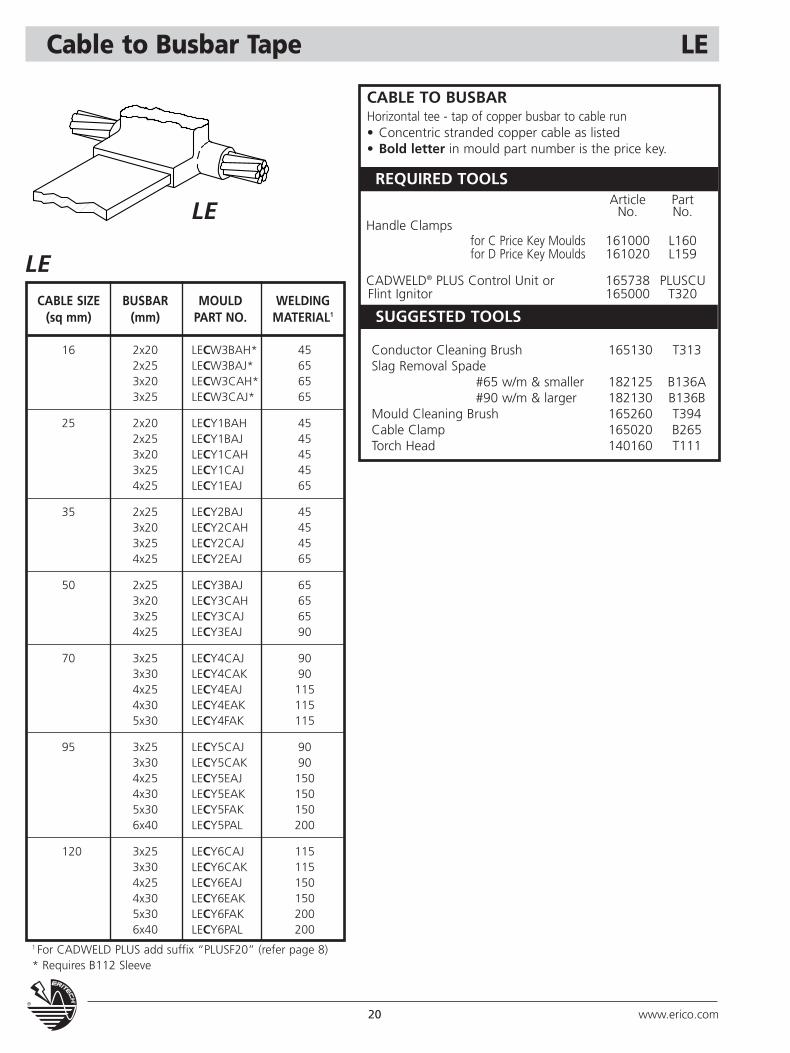
Cable to Busbar Tape LE
LECABLE SIZE BUSBAR MOULD WELDING
(sq mm) (mm) PART NO. MATERIAL1
16 2x20 LECW3BAH* 452x25 LECW3BAJ* 653x20 LECW3CAH* 653x25 LECW3CAJ* 65
25 2x20 LECY1BAH 452x25 LECY1BAJ 453x20 LECY1CAH 453x25 LECY1CAJ 454x25 LECY1EAJ 65
35 2x25 LECY2BAJ 453x20 LECY2CAH 453x25 LECY2CAJ 454x25 LECY2EAJ 65
50 2x25 LECY3BAJ 653x20 LECY3CAH 653x25 LECY3CAJ 654x25 LECY3EAJ 90
70 3x25 LECY4CAJ 903x30 LECY4CAK 904x25 LECY4EAJ 1154x30 LECY4EAK 1155x30 LECY4FAK 115
95 3x25 LECY5CAJ 903x30 LECY5CAK 904x25 LECY5EAJ 1504x30 LECY5EAK 1505x30 LECY5FAK 1506x40 LECY5PAL 200
120 3x25 LECY6CAJ 1153x30 LECY6CAK 1154x25 LECY6EAJ 1504x30 LECY6EAK 1505x30 LECY6FAK 2006x40 LECY6PAL 200
LE
CABLE TO BUSBAR Horizontal tee - tap of copper busbar to cable run• Concentric stranded copper cable as listed• Bold letter in mould part number is the price key.
SUGGESTED TOOLS
REQUIRED TOOLSArticle Part
No. No.Handle Clamps
for C Price Key Moulds 161000 L160for D Price Key Moulds 161020 L159
CADWELD® PLUS Control Unit or 165738 PLUSCUFlint Ignitor 165000 T320
Conductor Cleaning Brush 165130 T313Slag Removal Spade
#65 w/m & smaller 182125 B136A#90 w/m & larger 182130 B136B
Mould Cleaning Brush 165260 T394Cable Clamp 165020 B265Torch Head 140160 T111
1 For CADWELD PLUS add suffix “PLUSF20” (refer page 8)* Requires B112 Sleeve
21www.erico.com
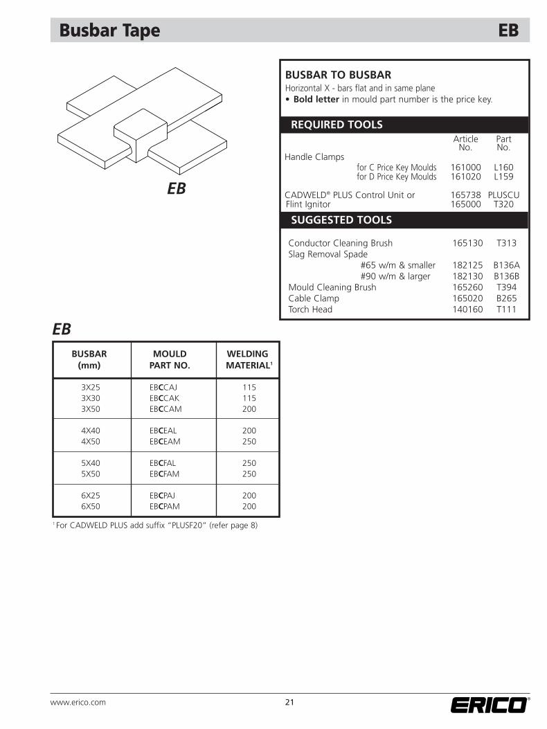
Busbar Tape EB
EB
BUSBAR TO BUSBARHorizontal X - bars flat and in same plane• Bold letter in mould part number is the price key.
SUGGESTED TOOLS
REQUIRED TOOLSArticle Part
No. No.Handle Clamps
for C Price Key Moulds 161000 L160for D Price Key Moulds 161020 L159
CADWELD® PLUS Control Unit or 165738 PLUSCUFlint Ignitor 165000 T320
Conductor Cleaning Brush 165130 T313Slag Removal Spade
#65 w/m & smaller 182125 B136A#90 w/m & larger 182130 B136B
Mould Cleaning Brush 165260 T394Cable Clamp 165020 B265Torch Head 140160 T111
EBBUSBAR MOULD WELDING
(mm) PART NO. MATERIAL1
3X25 EBCCAJ 1153X30 EBCCAK 1153X50 EBCCAM 200
4X40 EBCEAL 2004X50 EBCEAM 250
5X40 EBCFAL 2505X50 EBCFAM 250
6X25 EBCPAJ 2006X50 EBCPAM 200
1 For CADWELD PLUS add suffix “PLUSF20” (refer page 8)
22 www.erico.com
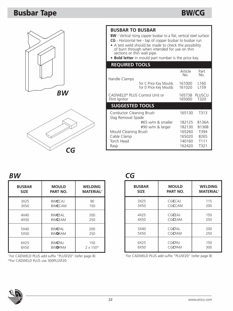
Busbar Tape BW/CG
BWBUSBAR MOULD WELDING
SIZE PART NO. MATERIAL1
3X25 BWCCAJ 903X50 BWCCAM 150
4X40 BWCEAL 2004X50 BWCEAM 250
5X40 BWCFAL 2005X50 BWDFAM 250
6X25 BWCPAJ 1506X50 BWDPAM 2 x 150*
BUSBAR TO BUSBARBW - Vertical rising copper busbar to a flat, vertical steel surfaceCG - Horizontal tee - tap of copper busbar to busbar run• A test weld should be made to check the possibility
of burn through when intended for use on thinsections or thin wall pipe.
• Bold letter in mould part number is the price key.
BW
CG
SUGGESTED TOOLS
REQUIRED TOOLSArticle Part
No. No.Handle Clamps
for C Price Key Moulds 161000 L160for D Price Key Moulds 161020 L159
CADWELD® PLUS Control Unit or 165738 PLUSCUFlint Ignitor 165000 T320
Conductor Cleaning Brush 165130 T313Slag Removal Spade
#65 w/m & smaller 182125 B136A#90 w/m & larger 182130 B136B
Mould Cleaning Brush 165260 T394Cable Clamp 165020 B265Torch Head 140160 T111Rasp 162420 T321
1 For CADWELD PLUS add suffix “PLUSF20” (refer page 8)*For CADWELD PLUS use 300PLUSF20
CGBUSBAR MOULD WELDING
SIZE PART NO. MATERIAL1
3X25 CGCCAJ 1153X50 CGCCAM 200
4X25 CGCEAJ 1504X50 CGCEAM 250
5X40 CGCFAL 2005X50 CGCFAM 250
6X25 CGCPAJ 1506X50 CGCPAM 300
1 For CADWELD PLUS add suffix “PLUSF20” (refer page 8)
23www.erico.com
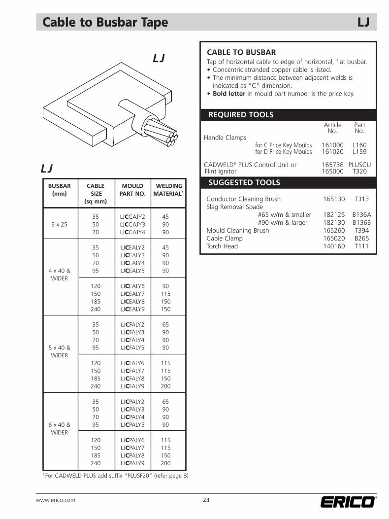
Cable to Busbar Tape LJ
LJBUSBAR CABLE MOULD WELDING
(mm) SIZE PART NO. MATERIAL1
(sq mm)
35 LJCCAJY2 453 x 25 50 LJCCAJY3 90
70 LJCCAJY4 90
35 LJCEALY2 4550 LJCEALY3 9070 LJCEALY4 90
4 x 40 & 95 LJCEALY5 90WIDER
120 LJCEALY6 90150 LJCEALY7 115185 LJCEALY8 150240 LJCEALY9 150
35 LJCFALY2 6550 LJCFALY3 9070 LJCFALY4 90
5 x 40 & 95 LJCFALY5 90WIDER
120 LJCFALY6 115150 LJCFALY7 115185 LJCFALY8 150240 LJCFALY9 200
35 LJCPALY2 6550 LJCPALY3 9070 LJCPALY4 90
6 x 40 & 95 LJCPALY5 90WIDER
120 LJCPALY6 115150 LJCPALY7 115185 LJCPALY8 150240 LJCPALY9 200
CABLE TO BUSBARTap of horizontal cable to edge of horizontal, flat busbar.• Concentric stranded copper cable is listed.• The minimum distance between adjacent welds is
indicated as “C” dimension.• Bold letter in mould part number is the price key.
LJ
SUGGESTED TOOLS
REQUIRED TOOLSArticle Part
No. No.Handle Clamps
for C Price Key Moulds 161000 L160for D Price Key Moulds 161020 L159
CADWELD® PLUS Control Unit or 165738 PLUSCUFlint Ignitor 165000 T320
Conductor Cleaning Brush 165130 T313Slag Removal Spade
#65 w/m & smaller 182125 B136A#90 w/m & larger 182130 B136B
Mould Cleaning Brush 165260 T394Cable Clamp 165020 B265Torch Head 140160 T111
1 For CADWELD PLUS add suffix “PLUSF20” (refer page 8)
24 www.erico.com
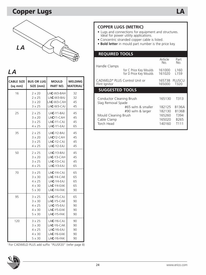
Copper Lugs LA
LACABLE SIZE BUS OR LUG MOULD WELDING
(sq mm) SIZE (mm) PART NO. MATERIAL1
16 2 x 20 LAC-W3-BAH 322 x 25 LAC-W3-BAJ 323 x 20 LAC-W3-CAH 453 x 25 LAC-W3-CAJ 45
25 2 x 25 LAC-Y1-BAJ 453 x 20 LACY1-CAH 453 x 25 LAC-Y1-CAJ 454 x 25 LAC-Y1-EAJ 65
35 2 x 25 LAC-Y2-BAJ 453 x 20 LACY2-CAH 453 x 25 LAC-Y2-CAJ 454 x 25 LAC-Y2-EAJ 45
50 2 x 25 LAC-Y3-BAJ 453 x 20 LAC-Y3-CAH 453 x 25 LAC-Y3-CAJ 454 x 25 LAC-Y3-EAJ 65
70 3 x 25 LAC-Y4-CAJ 653 x 30 LAC-Y4-CAK 654 x 25 LAC-Y4-EAJ 654 x 30 LAC-Y4-EAK 655 x 30 LAC-Y4-FAK 90
95 3 x 25 LAC-Y5-CAJ 653 x 30 LAC-Y5-CAK 904 x 25 LAC-Y5-EAJ 904 x 30 LAC-Y5-EAK 905 x 30 LAC-Y5-FAK 90
120 3 x 25 LAC-Y6-CAJ 903 x 30 LAC-Y6-CAK 904 x 25 LAC-Y6-EAJ 904 x 30 LAC-Y6-EAK 905 x 30 LAC-Y6-FAK 90
COPPER LUGS (METRIC)• Lugs and connections for equipment and structures.
Ideal for power utility applications.• Concentric stranded copper cable is listed.• Bold letter in mould part number is the price key.
LA
SUGGESTED TOOLS
REQUIRED TOOLSArticle Part
No. No.Handle Clamps
for C Price Key Moulds 161000 L160for D Price Key Moulds 161020 L159
CADWELD® PLUS Control Unit or 165738 PLUSCUFlint Ignitor 165000 T320
Conductor Cleaning Brush 165130 T313Slag Removal Spade
#65 w/m & smaller 182125 B136A#90 w/m & larger 182130 B136B
Mould Cleaning Brush 165260 T394Cable Clamp 165020 B265Torch Head 140160 T111
1 For CADWELD PLUS add suffix “PLUSF20” (refer page 8)
25www.erico.com
Copper Lugs GL
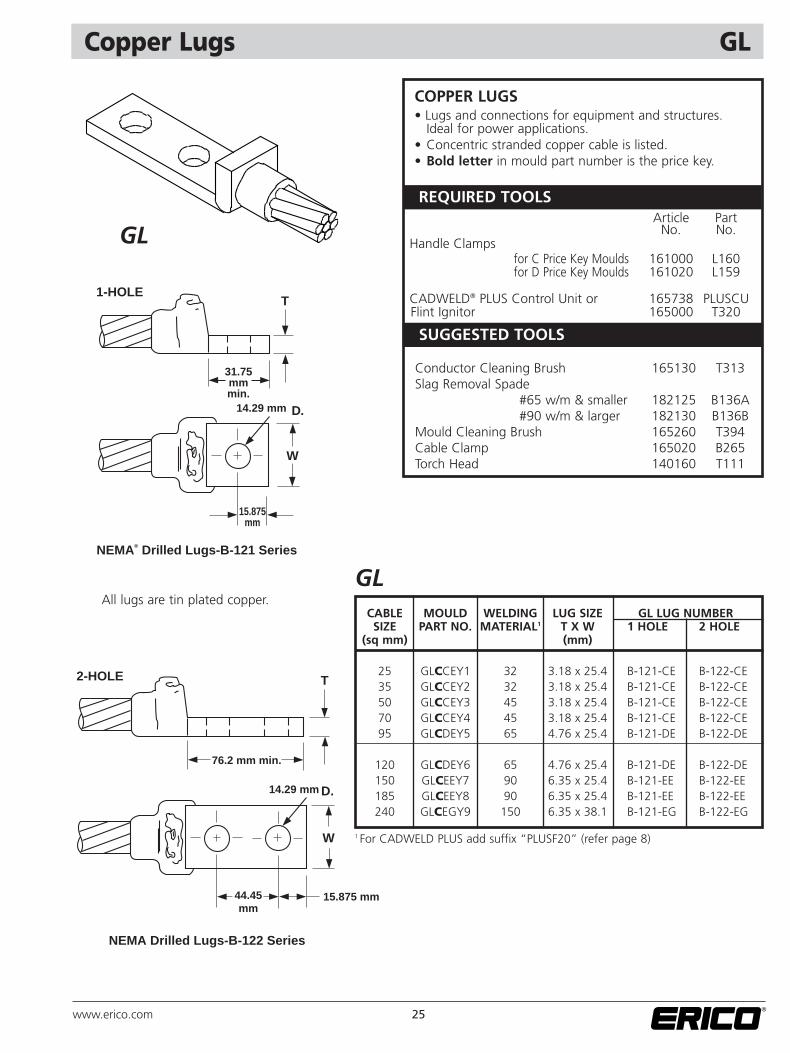
GLCABLE MOULD WELDING LUG SIZE GL LUG NUMBERSIZE PART NO. MATERIAL1 T X W 1 HOLE 2 HOLE
(sq mm) (mm)
25 GLCCEY1 32 3.18 x 25.4 B-121-CE B-122-CE35 GLCCEY2 32 3.18 x 25.4 B-121-CE B-122-CE50 GLCCEY3 45 3.18 x 25.4 B-121-CE B-122-CE70 GLCCEY4 45 3.18 x 25.4 B-121-CE B-122-CE95 GLCDEY5 65 4.76 x 25.4 B-121-DE B-122-DE
120 GLCDEY6 65 4.76 x 25.4 B-121-DE B-122-DE150 GLCEEY7 90 6.35 x 25.4 B-121-EE B-122-EE185 GLCEEY8 90 6.35 x 25.4 B-121-EE B-122-EE240 GLCEGY9 150 6.35 x 38.1 B-121-EG B-122-EG
NEMA® Drilled Lugs-B-121 Series
1-HOLE
31.75mmmin.
14.29 mm D.
W
15.875mm
T
NEMA Drilled Lugs-B-122 Series
2-HOLE
76.2 mm min.
14.29 mm D.
W
15.875 mm
T
44.45mm
COPPER LUGS • Lugs and connections for equipment and structures.
Ideal for power applications. • Concentric stranded copper cable is listed.• Bold letter in mould part number is the price key.
GL
All lugs are tin plated copper.
SUGGESTED TOOLS
REQUIRED TOOLSArticle Part
No. No.Handle Clamps
for C Price Key Moulds 161000 L160for D Price Key Moulds 161020 L159
CADWELD® PLUS Control Unit or 165738 PLUSCUFlint Ignitor 165000 T320
Conductor Cleaning Brush 165130 T313Slag Removal Spade
#65 w/m & smaller 182125 B136A#90 w/m & larger 182130 B136B
Mould Cleaning Brush 165260 T394Cable Clamp 165020 B265Torch Head 140160 T111
1 For CADWELD PLUS add suffix “PLUSF20” (refer page 8)
26 www.erico.com
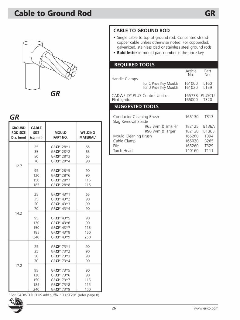
Cable to Ground Rod GR
CABLE TO GROUND ROD• Single cable to top of ground rod. Concentric strand
copper cable unless otherwise noted. For copperclad, galvanized, stainless clad or stainless steel ground rods.
• Bold letter in mould part number is the price key.
GRGROUND CABLEROD SIZE SIZE MOULD WELDINGDia. (mm) (sq mm) PART NO. MATERIAL1
25 GRCP128Y1 6535 GRCP128Y2 6550 GRCP128Y3 6570 GRCP128Y4 90
12.795 GRCP128Y5 90120 GRCP128Y6 90150 GRCP128Y7 115185 GRCP128Y8 115
25 GRCP143Y1 6535 GRCP143Y2 9050 GRCP143Y3 9070 GRCP143Y4 90
14.295 GRCP143Y5 90120 GRCP143Y6 90150 GRCP143Y7 115185 GRCP143Y8 150240 GRCP143Y9 250
25 GRCP173Y1 9035 GRCP173Y2 9050 GRCP173Y3 9070 GRCP173Y4 90
17.295 GRCP173Y5 90120 GRCP173Y6 90150 GRCP173Y7 115185 GRCP173Y8 115240 GRCP173Y9 150
GR
SUGGESTED TOOLS
REQUIRED TOOLSArticle Part
No. No.Handle Clamps
for C Price Key Moulds 161000 L160for D Price Key Moulds 161020 L159
CADWELD® PLUS Control Unit or 165738 PLUSCUFlint Ignitor 165000 T320
Conductor Cleaning Brush 165130 T313Slag Removal Spade
#65 w/m & smaller 182125 B136A#90 w/m & larger 182130 B136B
Mould Cleaning Brush 165260 T394Cable Clamp 165020 B265File 165260 T329Torch Head 140160 T111
1 For CADWELD PLUS add suffix “PLUSF20” (refer page 8)
27www.erico.com
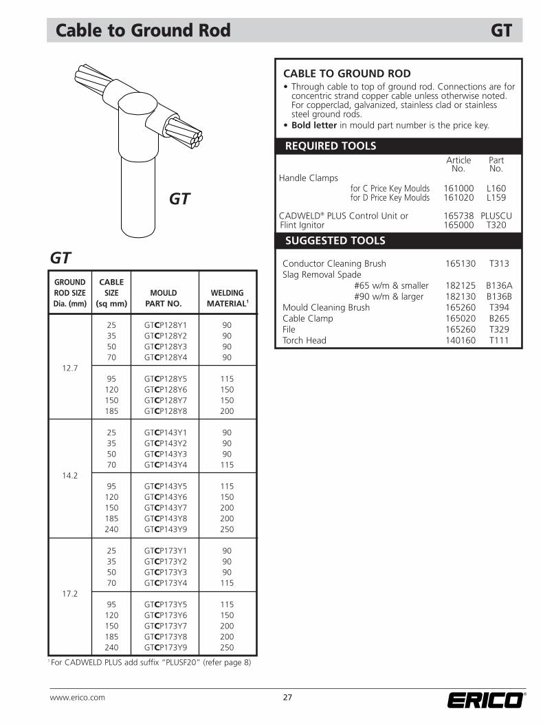
Cable to Ground Rod GT
CABLE TO GROUND ROD• Through cable to top of ground rod. Connections are for
concentric strand copper cable unless otherwise noted.For copperclad, galvanized, stainless clad or stainless steel ground rods.
• Bold letter in mould part number is the price key.
GTGROUND CABLEROD SIZE SIZE MOULD WELDINGDia. (mm) (sq mm) PART NO. MATERIAL1
25 GTCP128Y1 9035 GTCP128Y2 9050 GTCP128Y3 9070 GTCP128Y4 90
12.795 GTCP128Y5 115120 GTCP128Y6 150150 GTCP128Y7 150185 GTCP128Y8 200
25 GTCP143Y1 9035 GTCP143Y2 9050 GTCP143Y3 9070 GTCP143Y4 115
14.295 GTCP143Y5 115120 GTCP143Y6 150150 GTCP143Y7 200185 GTCP143Y8 200240 GTCP143Y9 250
25 GTCP173Y1 9035 GTCP173Y2 9050 GTCP173Y3 9070 GTCP173Y4 115
17.295 GTCP173Y5 115120 GTCP173Y6 150150 GTCP173Y7 200185 GTCP173Y8 200240 GTCP173Y9 250
GT
SUGGESTED TOOLS
REQUIRED TOOLSArticle Part
No. No.Handle Clamps
for C Price Key Moulds 161000 L160for D Price Key Moulds 161020 L159
CADWELD® PLUS Control Unit or 165738 PLUSCUFlint Ignitor 165000 T320
Conductor Cleaning Brush 165130 T313Slag Removal Spade
#65 w/m & smaller 182125 B136A#90 w/m & larger 182130 B136B
Mould Cleaning Brush 165260 T394Cable Clamp 165020 B265File 165260 T329Torch Head 140160 T111
1 For CADWELD PLUS add suffix “PLUSF20” (refer page 8)
28 www.erico.com
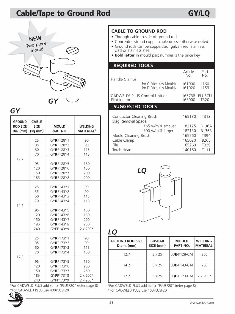
Cable/Tape to Ground Rod GY/LQ
CABLE TO GROUND ROD• Through cable to side of ground rod.• Concentric strand copper cable unless otherwise noted.• Ground rods can be copperclad, galvanized, stainless
clad or stainless steel.• Bold letter in mould part number is the price key.
GROUND CABLEROD SIZE SIZE MOULD WELDINGDia. (mm) (sq mm) PART NO. MATERIAL1
25 GYRP128Y1 9035 GYRP128Y2 9050 GYRP128Y3 11570 GYRP128Y4 115
12.795 GYRP128Y5 150120 GYRP128Y6 150150 GYRP128Y7 200185 GYRP128Y8 200
25 GYRP143Y1 9035 GYRP143Y2 9050 GYRP143Y3 11570 GYRP143Y4 115
14.295 GYRP143Y5 150120 GYRP143Y6 150150 GYRP143Y7 200185 GYRP143Y8 250240 GYFP143Y9 2 x 200*
25 GYRP173Y1 9035 GYRP173Y2 9050 GYRP173Y3 11570 GYRP173Y4 150
17.295 GYRP173Y5 150120 GYRP173Y6 250150 GYRP173Y7 250185 GYFP173Y8 2 x 200*240 GYFP173Y9 2 x 200*
GROUND ROD SIZE BUSBAR MOULD WELDINGDiam. (mm) SIZE (mm) PART NO. MATERIAL1
12.7 3 x 25 LQE-P128-CAJ 200
14.2 3 x 25 LQE-P143-CAJ 200
17.2 3 x 25 LQE-P173-CAJ 2 x 200*
LQ
LQ
GYSUGGESTED TOOLS
REQUIRED TOOLSArticle Part
No. No.Handle Clamps
for C Price Key Moulds 161000 L160for D Price Key Moulds 161020 L159
CADWELD® PLUS Control Unit or 165738 PLUSCUFlint Ignitor 165000 T320
Conductor Cleaning Brush 165130 T313Slag Removal Spade
#65 w/m & smaller 182125 B136A#90 w/m & larger 182130 B136B
Mould Cleaning Brush 165260 T394Cable Clamp 165020 B265File 165260 T329Torch Head 140160 T111
1 For CADWELD PLUS add suffix “PLUSF20” (refer page 8)*For CADWELD PLUS use 400PLUSF20
1 For CADWELD PLUS add suffix “PLUSF20” (refer page 8)*For CADWELD PLUS use 400PLUSF20
GY
NEWTwo-piece
mould
29www.erico.com
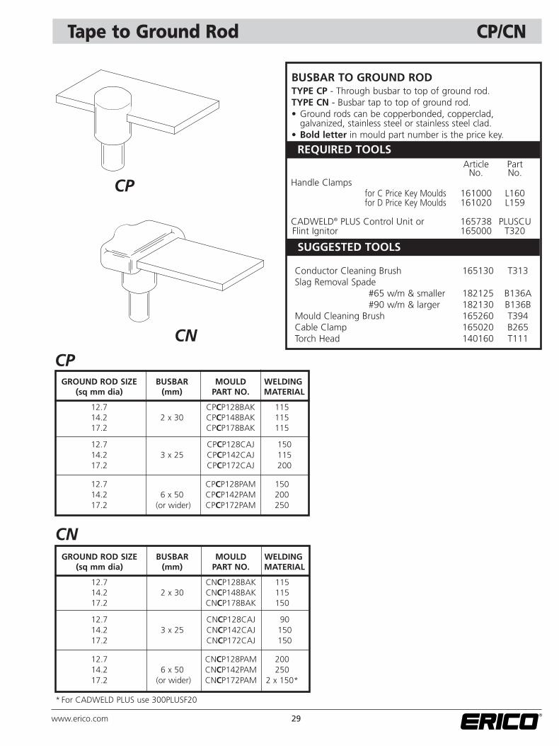
Tape to Ground Rod CP/CN
GROUND ROD SIZE BUSBAR MOULD WELDING(sq mm dia) (mm) PART NO. MATERIAL
12.7 CPCP128BAK 11514.2 2 x 30 CPCP148BAK 11517.2 CPCP178BAK 115
12.7 CPCP128CAJ 15014.2 3 x 25 CPCP142CAJ 11517.2 CPCP172CAJ 200
12.7 CPCP128PAM 15014.2 6 x 50 CPCP142PAM 20017.2 (or wider) CPCP172PAM 250
CP
GROUND ROD SIZE BUSBAR MOULD WELDING(sq mm dia) (mm) PART NO. MATERIAL
12.7 CNCP128BAK 11514.2 2 x 30 CNCP148BAK 11517.2 CNCP178BAK 150
12.7 CNCP128CAJ 9014.2 3 x 25 CNCP142CAJ 15017.2 CNCP172CAJ 150
12.7 CNCP128PAM 20014.2 6 x 50 CNCP142PAM 25017.2 (or wider) CNCP172PAM 2 x 150*
CN
CP
CN
BUSBAR TO GROUND RODTYPE CP - Through busbar to top of ground rod.TYPE CN - Busbar tap to top of ground rod.• Ground rods can be copperbonded, copperclad,
galvanized, stainless steel or stainless steel clad.• Bold letter in mould part number is the price key.
SUGGESTED TOOLS
REQUIRED TOOLSArticle Part
No. No.Handle Clamps
for C Price Key Moulds 161000 L160for D Price Key Moulds 161020 L159
CADWELD® PLUS Control Unit or 165738 PLUSCUFlint Ignitor 165000 T320
Conductor Cleaning Brush 165130 T313Slag Removal Spade
#65 w/m & smaller 182125 B136A#90 w/m & larger 182130 B136B
Mould Cleaning Brush 165260 T394Cable Clamp 165020 B265Torch Head 140160 T111
* For CADWELD PLUS use 300PLUSF20
30 www.erico.com
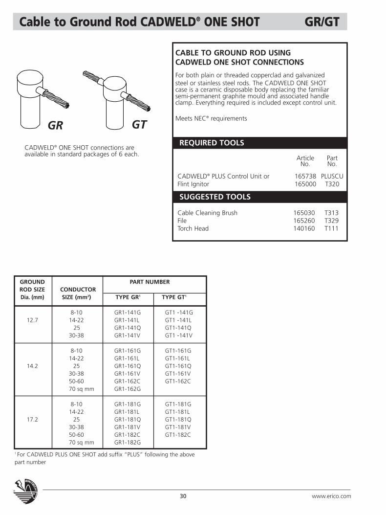
Cable to Ground Rod CADWELD® ONE SHOT GR/GT
CABLE TO GROUND ROD USING CADWELD ONE SHOT CONNECTIONS
For both plain or threaded copperclad and galvanizedsteel or stainless steel rods. The CADWELD ONE SHOT case is a ceramic disposable body replacing the familiar semi-permanent graphite mould and associated handle clamp. Everything required is included except control unit.
Meets NEC® requirementsGR GT
CADWELD® ONE SHOT connections areavailable in standard packages of 6 each.
GROUND PART NUMBERROD SIZE CONDUCTORDia. (mm) SIZE (mm2) TYPE GR1 TYPE GT1
8-10 GR1-141G GT1 -141G12.7 14-22 GR1-141L GT1 -141L
25 GR1-141Q GT1-141Q30-38 GR1-141V GT1 -141V
8-10 GR1-161G GT1-161G14-22 GR1-161L GT1-161L
14.2 25 GR1-161Q GT1-161Q30-38 GR1-161V GT1-161V50-60 GR1-162C GT1-162C70 sq mm GR1-162G
8-10 GR1-181G GT1-181G14-22 GR1-181L GT1-181L
17.2 25 GR1-181Q GT1-181Q30-38 GR1-181V GT1-181V50-60 GR1-182C GT1-182C70 sq mm GR1-182G
SUGGESTED TOOLS
REQUIRED TOOLS
Article PartNo. No.
CADWELD® PLUS Control Unit or 165738 PLUSCUFlint Ignitor 165000 T320
Cable Cleaning Brush 165030 T313File 165260 T329Torch Head 140160 T111
1 For CADWELD PLUS ONE SHOT add suffix “PLUS” following the abovepart number
31www.erico.com
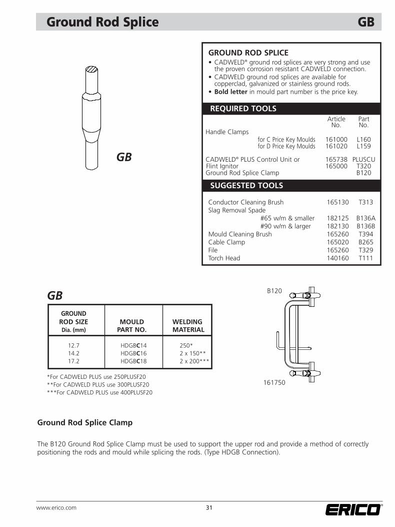
Ground Rod Splice GB
GROUND ROD SPLICE• CADWELD® ground rod splices are very strong and use
the proven corrosion resistant CADWELD connection.• CADWELD ground rod splices are available for
copperclad, galvanized or stainless ground rods.• Bold letter in mould part number is the price key.
GBGROUND
ROD SIZE MOULD WELDINGDia. (mm) PART NO. MATERIAL
12.7 HDGBC14 250*14.2 HDGBC16 2 x 150**17.2 HDGBC18 2 x 200***
*For CADWELD PLUS use 250PLUSF20**For CADWELD PLUS use 300PLUSF20***For CADWELD PLUS use 400PLUSF20
GB
Ground Rod Splice Clamp
The B120 Ground Rod Splice Clamp must be used to support the upper rod and provide a method of correctlypositioning the rods and mould while splicing the rods. (Type HDGB Connection).
B120
161750
SUGGESTED TOOLS
REQUIRED TOOLSArticle Part
No. No.Handle Clamps
for C Price Key Moulds 161000 L160for D Price Key Moulds 161020 L159
CADWELD® PLUS Control Unit or 165738 PLUSCUFlint Ignitor 165000 T320 Ground Rod Splice Clamp B120
Conductor Cleaning Brush 165130 T313Slag Removal Spade
#65 w/m & smaller 182125 B136A#90 w/m & larger 182130 B136B
Mould Cleaning Brush 165260 T394Cable Clamp 165020 B265File 165260 T329Torch Head 140160 T111
32 www.erico.com
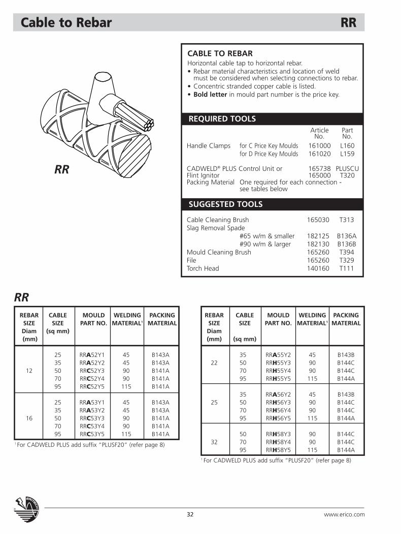
Cable to Rebar RR
RRREBAR CABLE MOULD WELDING PACKING
SIZE SIZE PART NO. MATERIAL1 MATERIALDiam (sq mm)(mm)
25 RRA52Y1 45 B143A35 RRA52Y2 45 B143A
12 50 RRC52Y3 90 B141A70 RRC52Y4 90 B141A95 RRC52Y5 115 B141A
25 RRA53Y1 45 B143A35 RRA53Y2 45 B143A
16 50 RRC53Y3 90 B141A70 RRC53Y4 90 B141A95 RRC53Y5 115 B141A
REBAR CABLE MOULD WELDING PACKINGSIZE SIZE PART NO. MATERIAL1 MATERIALDiam(mm) (sq mm)
35 RRA55Y2 45 B143B22 50 RRH55Y3 90 B144C
70 RRH55Y4 90 B144C95 RRH55Y5 115 B144A
35 RRA56Y2 45 B143B25 50 RRH56Y3 90 B144C
70 RRH56Y4 90 B144C95 RRH56Y5 115 B144A
50 RRH58Y3 90 B144C32 70 RRH58Y4 90 B144C
95 RRH58Y5 115 B144A
CABLE TO REBARHorizontal cable tap to horizontal rebar.• Rebar material characteristics and location of weld
must be considered when selecting connections to rebar.• Concentric stranded copper cable is listed.• Bold letter in mould part number is the price key.
RR
SUGGESTED TOOLS
REQUIRED TOOLSArticle Part
No. No.Handle Clamps for C Price Key Moulds 161000 L160
for D Price Key Moulds 161020 L159
CADWELD® PLUS Control Unit or 165738 PLUSCUFlint Ignitor 165000 T320 Packing Material One required for each connection -
see tables below
Cable Cleaning Brush 165030 T313Slag Removal Spade
#65 w/m & smaller 182125 B136A#90 w/m & larger 182130 B136B
Mould Cleaning Brush 165260 T394File 165260 T329Torch Head 140160 T111
1 For CADWELD PLUS add suffix “PLUSF20” (refer page 8)
1 For CADWELD PLUS add suffix “PLUSF20” (refer page 8)
33www.erico.com
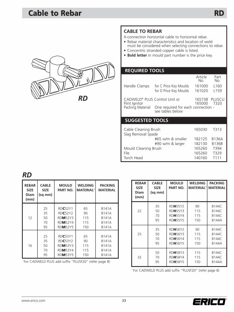
Cable to Rebar RD
RDREBAR CABLE MOULD WELDING PACKING
SIZE SIZE PART NO. MATERIAL1 MATERIALDiam (sq mm)(mm)
25 RDC52Y1 65 B141A35 RDC52Y2 90 B141A
12 50 RDM52Y3 115 B141A70 RDM52Y4 115 B141A95 RDM52Y5 150 B141A
25 RDC53Y1 65 B141A35 RDC53Y2 90 B141A
16 50 RDM53Y3 115 B141A70 RDM53Y4 115 B141A95 RDM53Y5 150 B141A
REBAR CABLE MOULD WELDING PACKINGSIZE SIZE PART NO. MATERIAL1 MATERIALDiam (sq mm)(mm)
35 RDH55Y2 90 B144C22 50 RDH55Y3 115 B144C
70 RDH55Y4 115 B144C95 RDH55Y5 150 B144A
35 RDH56Y2 90 B144C25 50 RDH56Y3 115 B144C
70 RDH56Y4 115 B144C95 RDH56Y5 150 B144A
50 RDH58Y3 115 B144C32 70 RDH58Y4 115 B144C
95 RDH58Y5 150 B144A
CABLE TO REBARX-connection horizontal cable to horizontal rebar.• Rebar material characteristics and location of weld
must be considered when selecting connections to rebar.• Concentric stranded copper cable is listed.• Bold letter in mould part number is the price key.
RD
SUGGESTED TOOLS
REQUIRED TOOLSArticle Part
No. No.Handle Clamps for C Price Key Moulds 161000 L160
for D Price Key Moulds 161020 L159
CADWELD® PLUS Control Unit or 165738 PLUSCUFlint Ignitor 165000 T320 Packing Material One required for each connection -
see tables below
Cable Cleaning Brush 165030 T313Slag Removal Spade
#65 w/m & smaller 182125 B136A#90 w/m & larger 182130 B136B
Mould Cleaning Brush 165260 T394File 165260 T329Torch Head 140160 T111
1 For CADWELD PLUS add suffix “PLUSF20” (refer page 8)
1 For CADWELD PLUS add suffix “PLUSF20” (refer page 8)
34 www.erico.com
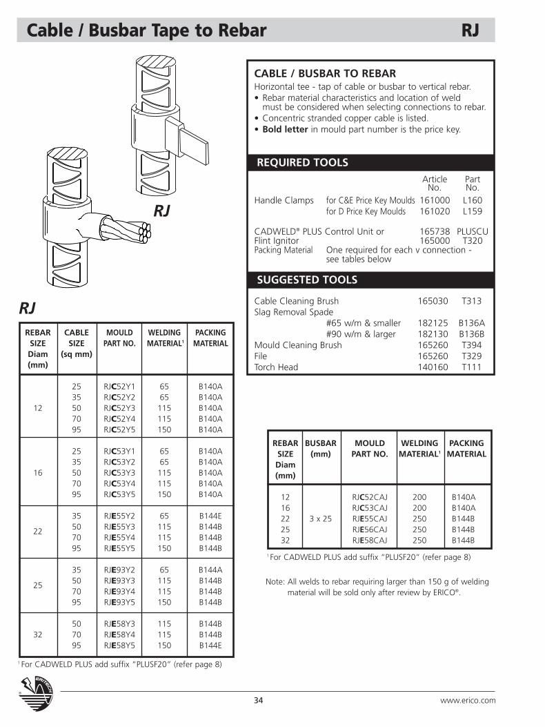
Cable / Busbar Tape to Rebar RJ
RJREBAR CABLE MOULD WELDING PACKING
SIZE SIZE PART NO. MATERIAL1 MATERIALDiam (sq mm)(mm)
25 RJC52Y1 65 B140A35 RJC52Y2 65 B140A
12 50 RJC52Y3 115 B140A70 RJC52Y4 115 B140A95 RJC52Y5 150 B140A
25 RJC53Y1 65 B140A35 RJC53Y2 65 B140A
16 50 RJC53Y3 115 B140A70 RJC53Y4 115 B140A95 RJC53Y5 150 B140A
35 RJE55Y2 65 B144E
22 50 RJE55Y3 115 B144B70 RJE55Y4 115 B144B95 RJE55Y5 150 B144B
35 RJE93Y2 65 B144A
25 50 RJE93Y3 115 B144B70 RJE93Y4 115 B144B95 RJE93Y5 150 B144B
50 RJE58Y3 115 B144B32 70 RJE58Y4 115 B144B
95 RJE58Y5 150 B144E
ACCESSORIES
CABLE / BUSBAR TO REBARHorizontal tee - tap of cable or busbar to vertical rebar.• Rebar material characteristics and location of weld
must be considered when selecting connections to rebar.• Concentric stranded copper cable is listed.• Bold letter in mould part number is the price key.
RJ
SUGGESTED TOOLS
REQUIRED TOOLSArticle Part
No. No.Handle Clamps for C&E Price Key Moulds 161000 L160
for D Price Key Moulds 161020 L159
CADWELD® PLUS Control Unit or 165738 PLUSCUFlint Ignitor 165000 T320 Packing Material One required for each v connection -
see tables below
Cable Cleaning Brush 165030 T313Slag Removal Spade
#65 w/m & smaller 182125 B136A#90 w/m & larger 182130 B136B
Mould Cleaning Brush 165260 T394File 165260 T329Torch Head 140160 T111
1 For CADWELD PLUS add suffix “PLUSF20” (refer page 8)
1 For CADWELD PLUS add suffix “PLUSF20” (refer page 8)
Note: All welds to rebar requiring larger than 150 g of weldingmaterial will be sold only after review by ERICO®.
REBAR BUSBAR MOULD WELDING PACKINGSIZE (mm) PART NO. MATERIAL1 MATERIALDiam(mm)
12 RJC52CAJ 200 B140A16 RJC53CAJ 200 B140A22 3 x 25 RJE55CAJ 250 B144B25 RJE56CAJ 250 B144B32 RJE58CAJ 250 B144B
35www.erico.com
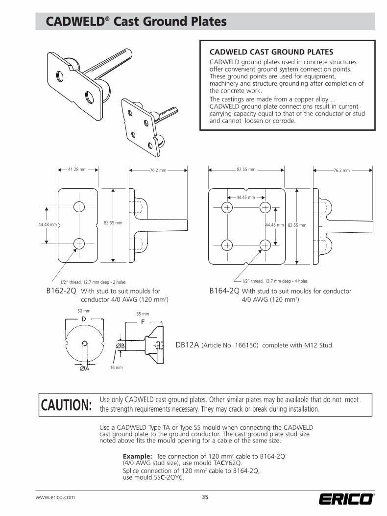
CADWELD® Cast Ground Plates
CADWELD CAST GROUND PLATESCADWELD ground plates used in concrete structuresoffer convenient ground system connection points.These ground points are used for equipment,machinery and structure grounding after completion ofthe concrete work.The castings are made from a copper alloy ...CADWELD ground plate connections result in currentcarrying capacity equal to that of the conductor or studand cannot loosen or corrode.
▲
▲
▲
▲
▲
▲
▲
▲
▲
▲
▲▲
▲
▲
▲
▲
▲
▲
▲
▲
Use only CADWELD cast ground plates. Other similar plates may be available that do not meetthe strength requirements necessary. They may crack or break during installation.
Use a CADWELD Type TA or Type SS mould when connecting the CADWELDcast ground plate to the ground conductor. The cast ground plate stud sizenoted above fits the mould opening for a cable of the same size.
Example: Tee connection of 120 mm2 cable to B164-2Q(4/0 AWG stud size), use mould TACY62Q.Splice connection of 120 mm2 cable to B164-2Q,use mould SSC-2QY6.
B162-2Q With stud to suit moulds forconductor 4/0 AWG (120 mm2)
DB12A (Article No. 166150) complete with M12 Stud
B164-2Q With stud to suit moulds for conductor 4/0 AWG (120 mm2)
CAUTION:
41.28 mm
50 mm55 mm
16 mm
44.48 mm 82.55 mm
1/2” thread, 12.7 mm deep - 2 holes 1/2” thread, 12.7 mm deep - 4 holes
76.2 mm 82.55 mm
82.55 mm
44.45 mm
44.45 mm
76.2 mm
36 www.erico.com
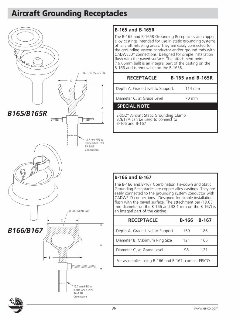
Aircraft Grounding Receptacles
RECEPTACLE B-165 and B-165R
Depth A, Grade Level to Support. 114 mm
Diameter C, at Grade Level 70 mm
B-165 and B-165RThe B-165 and B-165R Grounding Receptacles are copperalloy castings intended for use in static grounding systemsof aircraft refueling areas. They are easily connected tothe grounding system conductor and/or ground rods withCADWELD® connections. Designed for simple installationflush with the paved surface. The attachment point(19.05mm ball) is an integral part of the casting on the B-165 and is removable on the B-165R.
ERICO® Aircraft Static Grounding ClampB2617A can be used to connect to B-166 and B-167
B-166 and B-167The B-166 and B-167 Combination Tie-down and StaticGrounding Receptacles are copper alloy castings. They areeasily connected to the grounding system conductor withCADWELD connections. Designed for simple installationflush with the paved surface. The attachment bar (19.05mm diameter on the B-166 and 38.1 mm on the B-167) isan integral part of the casting.
RECEPTACLE B-166 B-167
Depth A, Grade Level to Support 159 185
Diameter B, Maximum Ring Size 121 165
Diameter C, at Grade Level 98 121
B165/B165R
B166/B167
For assemblies using B-166 and B-167, contact ERICO.
SPECIAL NOTE
BALL, 19.05 mm DIA.
ATTACHMENT BAR
12.7 mm PIPE tolocate when TYPERA & RBConnections
12.7 mm PIPE tolocate when TYPERA & RBConnections
C
C
B
A
A
37www.erico.com
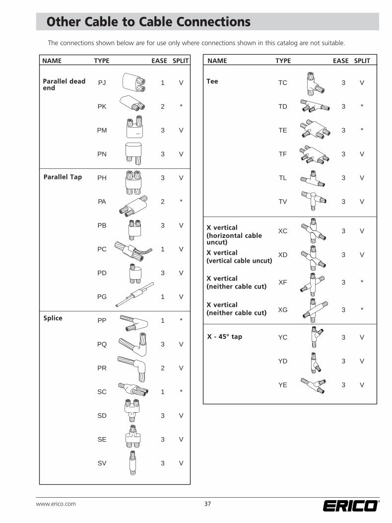
Other Cable to Cable ConnectionsThe connections shown below are for use only where connections shown in this catalog are not suitable.
PJ 1 V
PK 2 *
PM 3 V
PN 3 V
PH 3 V
PA 2 *
PB 3 V
PC 1 V
PD 3 V
PG 1 V
PP 1 *
PQ 3 V
PR 2 V
SC 1 *
SD 3 V
SE 3 V
SV 3 V
NAME TYPE EASE SPLIT
Parallel deadend
Parallel Tap
Splice
TC 3 V
TD 3 *
TE 3 *
TF 3 V
TL 3 V
TV 3 V
XC 3 V
XD 3 V
XF 3 *
XG 3 *
YC 3 V
YD 3 V
YE 3 V
NAME TYPE EASE SPLIT
Tee
X vertical(horizontal cableuncut)
X vertical(vertical cable uncut)
X vertical(neither cable cut)
X vertical(neither cable cut)
X - 45° tap
38 www.erico.com
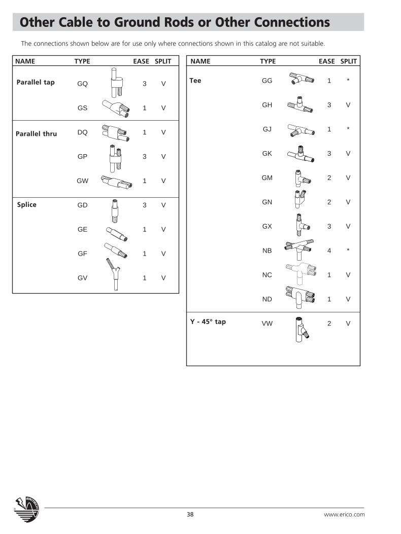
Other Cable to Ground Rods or Other Connections
GQ 3 V
GS 1 V
DQ 1 V
GP 3 V
GW 1 V
GD 3 V
GE 1 V
GF 1 V
GV 1 V
GG 1 *
GH 3 V
GJ 1 *
GK 3 V
GM 2 V
GN 2 V
GX 3 V
NB 4 *
NC 1 V
ND 1 V
VW 2 V
NAME TYPE EASE SPLIT
Parallel tap
Parallel thru
Splice
Tee
NAME TYPE EASE SPLIT
Y - 45° tap
The connections shown below are for use only where connections shown in this catalog are not suitable.
39www.erico.com
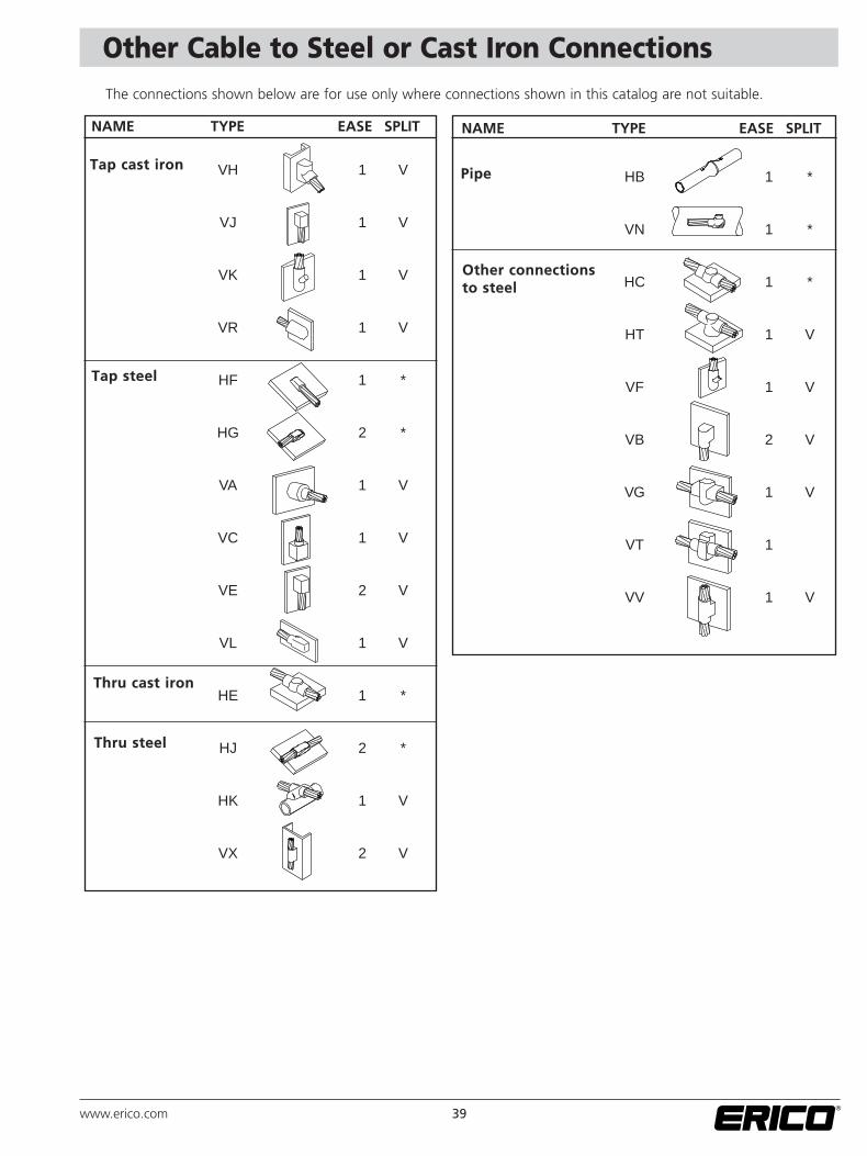
Other Cable to Steel or Cast Iron ConnectionsThe connections shown below are for use only where connections shown in this catalog are not suitable.
VH 1 V
VJ 1 V
VK 1 V
VR 1 V
HF 1 *
HG 2 *
VA 1 V
VC 1 V
VE 2 V
VL 1 V
HE 1 *
HJ 2 *
HK 1 V
VX 2 V
HB 1 *
VN 1 *
HC 1 *
HT 1 V
VF 1 V
VB 2 V
VG 1 V
VT 1
VV 1 V
NAME TYPE EASE SPLIT
Tap cast iron
Tap steel
Thru cast iron
Thru steel
NAME TYPE EASE SPLIT
Pipe
Other connectionsto steel
40 www.erico.com
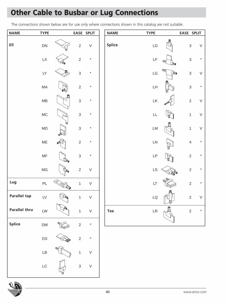
Other Cable to Busbar or Lug Connections
DN 2 V
LX 2 *
LY 3 *
MA 2 *
MB 3 *
MC 3 *
MD 3 *
ME 2 *
MF 3 *
MG 2 V
PL 1 V
LV 1 V
LW 1 V
DM 2 *
DS 2 *
LB 1 V
LC 3 V
NAME TYPE EASE SPLIT
Ell
Lug
Parallel tap
Parallel thru
Splice
Tee
LD 3 V
LF 3 *
LG 3 V
LH 3 *
LK 2 V
LL 1 V
LM 1 V
LN 4 *
LP 2 *
LS 2 *
LT 2 *
LQ 2 V
LR 2 *
NAME TYPE EASE SPLIT
Splice
The connections shown below are for use only where connections shown in this catalog are not suitable.
41www.erico.com
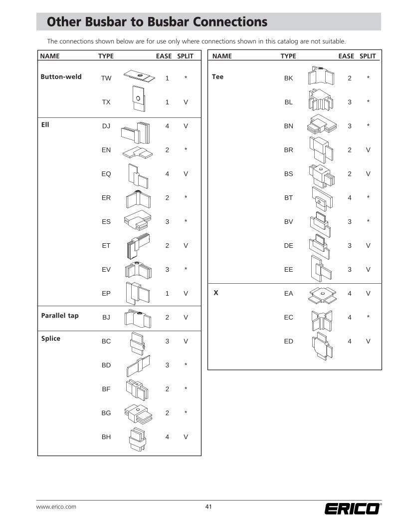
TW 1 *
TX 1 V
DJ 4 V
EN 2 *
EQ 4 V
ER 2 *
ES 3 *
ET 2 V
EV 3 *
EP 1 V
BJ 2 V
BC 3 V
BD 3 *
BF 2 *
BG 2 *
BH 4 V
NAME TYPE EASE SPLIT
Button-weld
Ell
Parallel tap
X
Splice
BK 2 *
BL 3 *
BN 3 *
BR 2 V
BS 2 V
BT 4 *
BV 3 *
DE 3 V
EE 3 V
EA 4 V
EC 4 *
ED 4 V
NAME TYPE EASE SPLIT
Tee
Other Busbar to Busbar ConnectionsThe connections shown below are for use only where connections shown in this catalog are not suitable.
42 www.erico.com
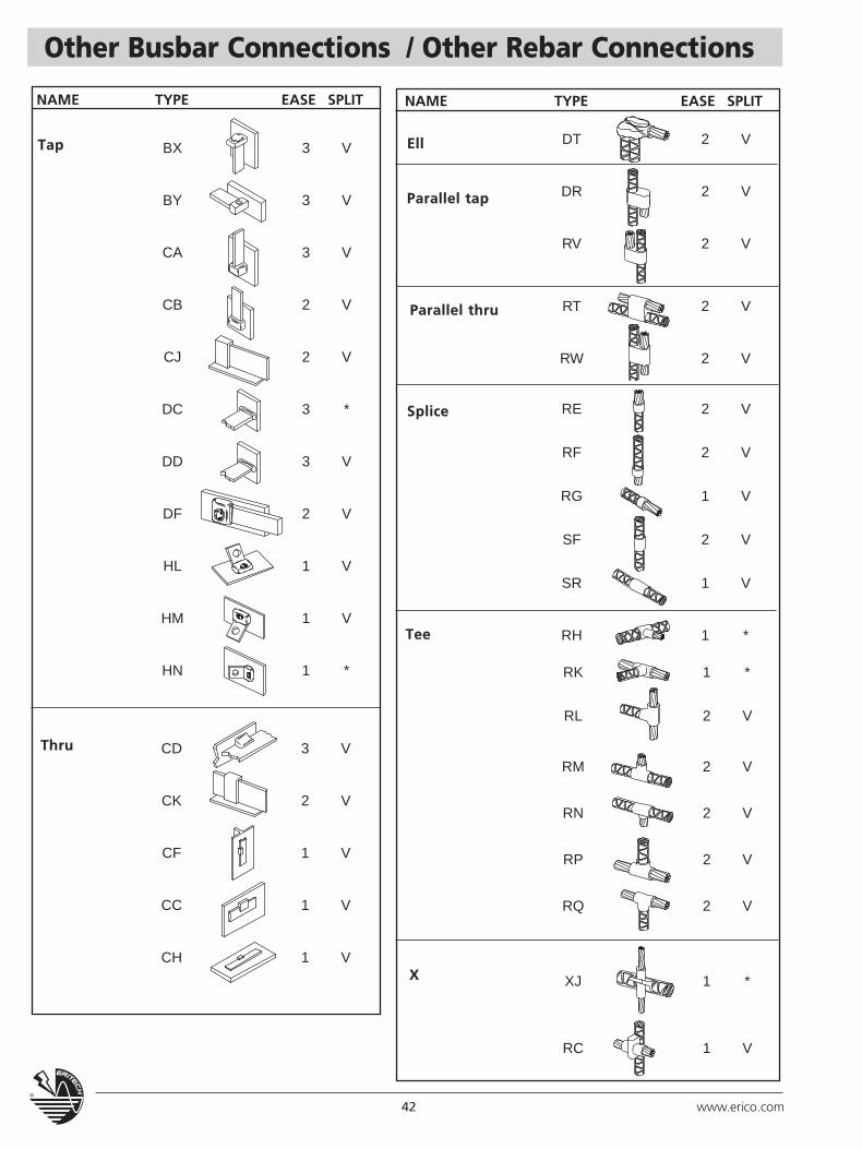
Other Busbar Connections / Other Rebar Connections
CD 3 V
CK 2 V
CF 1 V
CC 1 V
CH 1 V
BX 3 V
BY 3 V
CA 3 V
CB 2 V
CJ 2 V
DC 3 *
DD 3 V
DF 2 V
HL 1 V
HM 1 V
HN 1 *
NAME TYPE EASE SPLIT
Tap
Thru
RK 1 *
RL 2 V
RM 2 V
RN 2 V
RP 2 V
RQ 2 V
XJ 1 *
RC 1 V
DT 2 V
DR 2 V
RV 2 V
RT 2 V
RW 2 V
RE 2 V
RF 2 V
RG 1 V
SF 2 V
SR 1 V
RH 1 *
NAME TYPE EASE SPLIT
Ell
Parallel tap
Parallel thru
X
Splice
Tee
43www.erico.com
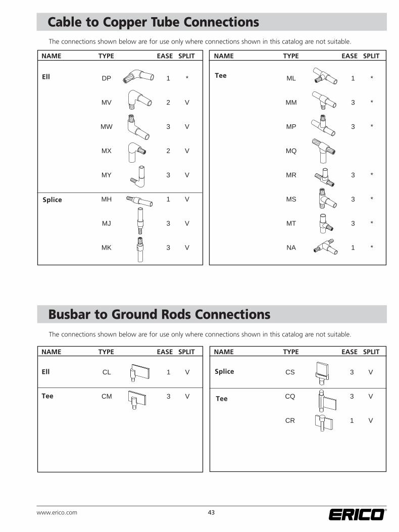
Cable to Copper Tube Connections
DP 1 *
MV 2 V
MW 3 V
MX 2 V
MY 3 V
MH 1 V
MJ 3 V
MK 3 V
NAME TYPE EASE SPLIT
Ell Tee ML 1 *
MM 3 *
MP 3 *
MQ
MR 3 *
MS 3 *
MT 3 *
NA 1 *
NAME TYPE EASE SPLIT
Splice
CL 1 V
CM 3 V
Ell
Tee Tee
Splice CS 3 V
CQ 3 V
CR 1 V
NAME TYPE EASE SPLIT NAME TYPE EASE SPLIT
BUS BAR TO GROUND RODSThe connections shown below are for use only where connections shown in this catalogue are not suitable
The connections shown below are for use only where connections shown in this catalog are not suitable.
Busbar to Ground Rods ConnectionsThe connections shown below are for use only where connections shown in this catalog are not suitable.
44 www.erico.com
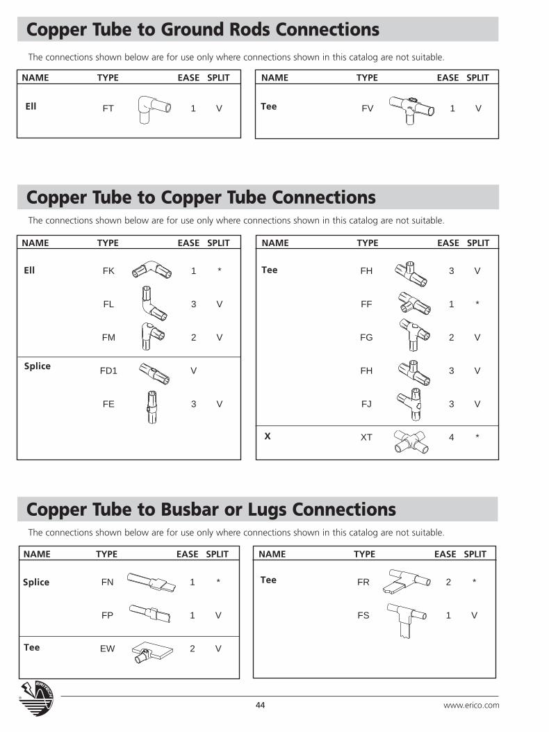
Copper Tube to Ground Rods ConnectionsThe connections shown below are for use only where connections shown in this catalog are not suitable.
Copper Tube to Copper Tube ConnectionsThe connections shown below are for use only where connections shown in this catalog are not suitable.
Copper Tube to Busbar or Lugs ConnectionsThe connections shown below are for use only where connections shown in this catalog are not suitable.
FT 1 V
NAME TYPE EASE SPLIT
Ell FV 1 V
NAME TYPE EASE SPLIT
Tee
FK 1 *
FL 3 V
FM 2 V
FD1 V
FE 3 V
Ell Tee
X
Splice
FH 3 V
FF 1 *
FG 2 V
FH 3 V
FJ 3 V
XT 4 *
NAME TYPE EASE SPLIT NAME TYPE EASE SPLIT
FN 1 *
FP 1 V
EW 2 VTee
TeeSplice FR 2 *
FS 1 V
NAME TYPE EASE SPLIT NAME TYPE EASE SPLIT
45www.erico.com
Material, Tools and Accessories
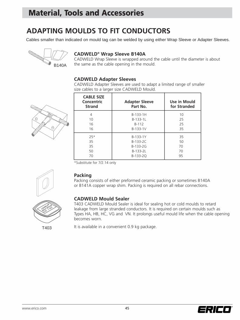
ADAPTING MOULDS TO FIT CONDUCTORS
CADWELD® Wrap Sleeve B140ACADWELD Wrap Sleeve is wrapped around the cable until the diameter is about the same as the cable opening in the mould.
CADWELD Adapter Sleeves CADWELD Adapter Sleeves are used to adapt a limited range of smaller size cables to a larger size CADWELD Mould.
CABLE SIZEConcentric Adapter Sleeve Use in Mould
Strand Part No. for Stranded
4 B-133-1H 1010 B-133-1L 2516 B-112 2516 B-133-1V 35
25* B-133-1Y 3535 B-133-2C 5035 B-133-2G 7050 B-133-2L 7070 B-133-2Q 95
*Substitute for 7/2.14 only
PackingPacking consists of either preformed ceramic packing or sometimes B140A or B141A copper wrap shim. Packing is required on all rebar connections.
CADWELD Mould SealerT403 CADWELD Mould Sealer is ideal for sealing hot or cold moulds to retard leakage from large stranded conductors. It is required on certain moulds such as Types HA, HB, HC, VG and VN. It prolongs useful mould life when the cable openingbecomes worn.
It is available in a convenient 0.9 kg package.
B140A
T403
Cables smaller than indicated on mould tag can be welded by using either Wrap Sleeve or Adapter Sleeves.
46 www.erico.com
T111
T372A
T319
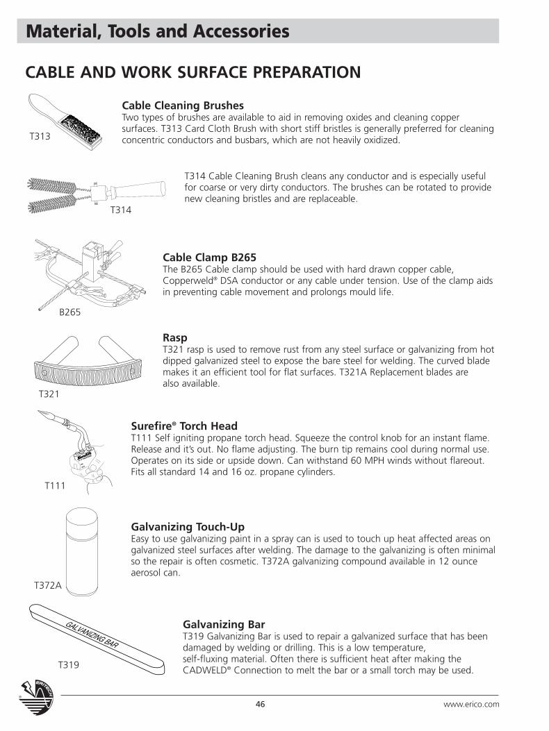
Surefire® Torch HeadT111 Self igniting propane torch head. Squeeze the control knob for an instant flame.Release and it’s out. No flame adjusting. The burn tip remains cool during normal use.Operates on its side or upside down. Can withstand 60 MPH winds without flareout.Fits all standard 14 and 16 oz. propane cylinders.
Galvanizing Touch-UpEasy to use galvanizing paint in a spray can is used to touch up heat affected areas on galvanized steel surfaces after welding. The damage to the galvanizing is often minimalso the repair is often cosmetic. T372A galvanizing compound available in 12 ounceaerosol can.
Galvanizing BarT319 Galvanizing Bar is used to repair a galvanized surface that has beendamaged by welding or drilling. This is a low temperature, self-fluxing material. Often there is sufficient heat after making the CADWELD® Connection to melt the bar or a small torch may be used.
Material, Tools and Accessories
CABLE AND WORK SURFACE PREPARATION
Cable Cleaning BrushesTwo types of brushes are available to aid in removing oxides and cleaning copper surfaces. T313 Card Cloth Brush with short stiff bristles is generally preferred for cleaningconcentric conductors and busbars, which are not heavily oxidized.
T314 Cable Cleaning Brush cleans any conductor and is especially usefulfor coarse or very dirty conductors. The brushes can be rotated to providenew cleaning bristles and are replaceable.
T313
T314
B265
T321
Cable Clamp B265The B265 Cable clamp should be used with hard drawn copper cable, Copperweld® DSA conductor or any cable under tension. Use of the clamp aidsin preventing cable movement and prolongs mould life.
RaspT321 rasp is used to remove rust from any steel surface or galvanizing from hotdipped galvanized steel to expose the bare steel for welding. The curved blademakes it an efficient tool for flat surfaces. T321A Replacement blades are also available.
Material, Tools and Accessories
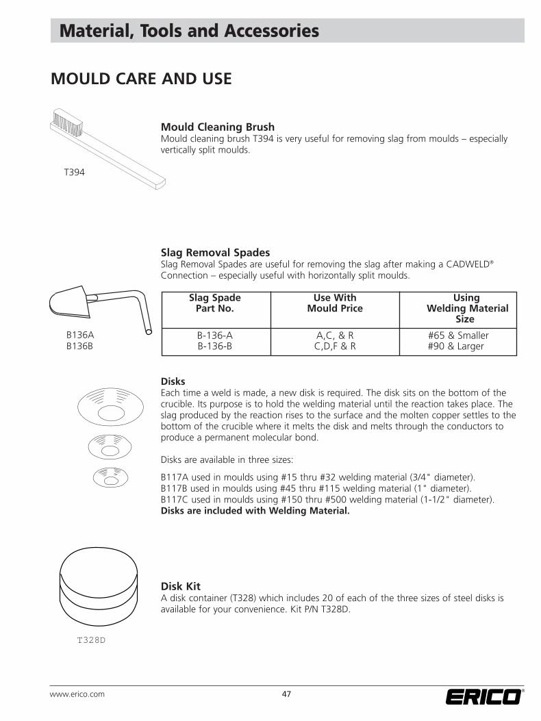
Mould Cleaning BrushMould cleaning brush T394 is very useful for removing slag from moulds – especially vertically split moulds.
Slag Removal SpadesSlag Removal Spades are useful for removing the slag after making a CADWELD®
Connection – especially useful with horizontally split moulds.
DisksEach time a weld is made, a new disk is required. The disk sits on the bottom of the crucible. Its purpose is to hold the welding material until the reaction takes place. Theslag produced by the reaction rises to the surface and the molten copper settles to thebottom of the crucible where it melts the disk and melts through the conductors to produce a permanent molecular bond.
Disks are available in three sizes:
B117A used in moulds using #15 thru #32 welding material (3/4" diameter).B117B used in moulds using #45 thru #115 welding material (1" diameter).B117C used in moulds using #150 thru #500 welding material (1-1/2" diameter).Disks are included with Welding Material.
Disk KitA disk container (T328) which includes 20 of each of the three sizes of steel disks isavailable for your convenience. Kit P/N T328D.
MOULD CARE AND USE
T394
B136AB136B
T328D
Slag Spade Use With UsingPart No. Mould Price Welding Material
Size
B-136-A A,C, & R #65 & SmallerB-136-B C,D,F & R #90 & Larger
47www.erico.com
Material, Tools and Accessories
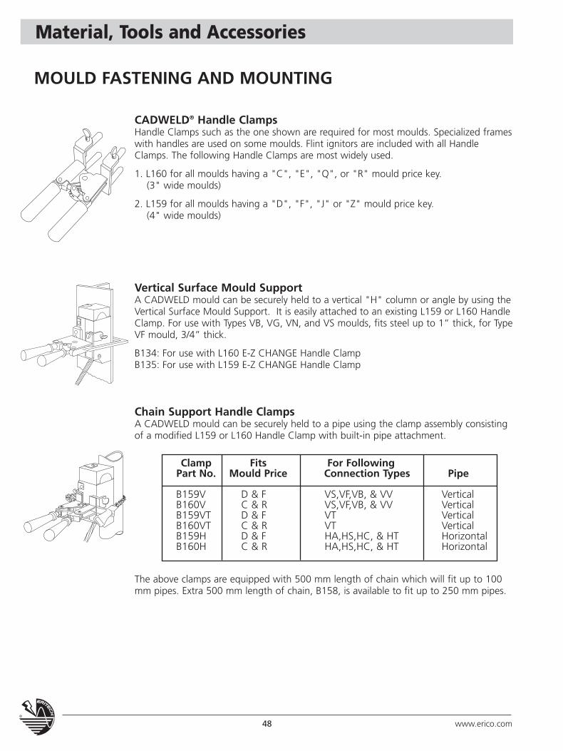
CADWELD® Handle ClampsHandle Clamps such as the one shown are required for most moulds. Specialized frameswith handles are used on some moulds. Flint ignitors are included with all HandleClamps. The following Handle Clamps are most widely used.
1. L160 for all moulds having a "C", "E", "Q", or "R" mould price key.(3" wide moulds)
2. L159 for all moulds having a "D", "F", "J" or "Z" mould price key.(4" wide moulds)
Vertical Surface Mould SupportA CADWELD mould can be securely held to a vertical "H" column or angle by using theVertical Surface Mould Support. It is easily attached to an existing L159 or L160 HandleClamp. For use with Types VB, VG, VN, and VS moulds, fits steel up to 1” thick, for TypeVF mould, 3/4” thick.
B134: For use with L160 E-Z CHANGE Handle ClampB135: For use with L159 E-Z CHANGE Handle Clamp
Chain Support Handle ClampsA CADWELD mould can be securely held to a pipe using the clamp assembly consistingof a modified L159 or L160 Handle Clamp with built-in pipe attachment.
Clamp Fits For FollowingPart No. Mould Price Connection Types Pipe
B159V D & F VS,VF,VB, & VV VerticalB160V C & R VS,VF,VB, & VV VerticalB159VT D & F VT VerticalB160VT C & R VT VerticalB159H D & F HA,HS,HC, & HT HorizontalB160H C & R HA,HS,HC, & HT Horizontal
The above clamps are equipped with 500 mm length of chain which will fit up to 100mm pipes. Extra 500 mm length of chain, B158, is available to fit up to 250 mm pipes.
MOULD FASTENING AND MOUNTING
48 www.erico.com
Material, Tools and Accessories
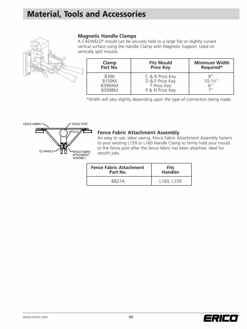
Magnetic Handle ClampsA CADWELD® mould can be securely held to a large flat or slightly curved vertical surface using the Handle Clamp with Magnetic Support. Used on vertically split moulds.
Fence Fabric Attachment AssemblyAn easy to use, labor saving, Fence Fabric Attachment Assembly fastensto your existing L159 or L160 Handle Clamp to firmly hold your mouldto the fence post after the fence fabric has been attached. Ideal forretrofit jobs.
FENCE FABRIC FENCE POST
MOULD
EZ HANDLE FENCE FABRICATTACHMENTASSEMBLY
Clamp Fits Mould Minimum WidthPart No. Price Key Required*
B396 C & R Price Key 8”B159M D & F Price Key 10-1/2”
B399AM T Price Key 6”B399BM P & N Price Key 7”
*Width will vary slightly depending upon the type of connection being made.
Fence Fabric Attachment FitsPart No. Handles
B827A L160, L159
49www.erico.com
Material, Tools and Accessories
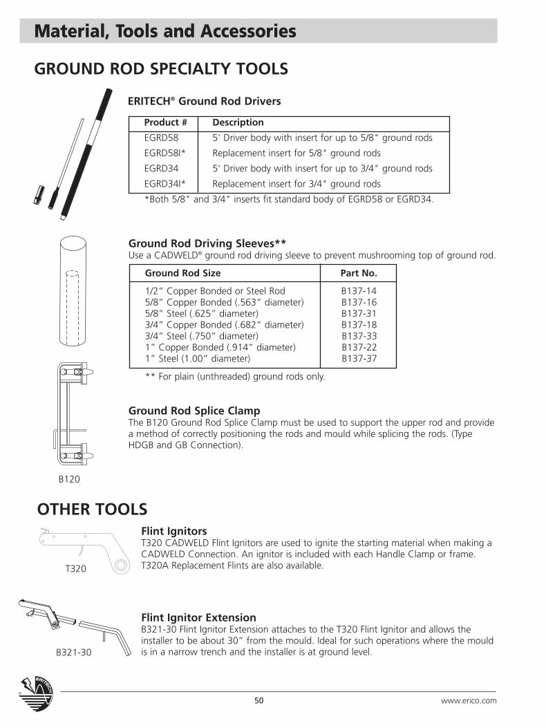
Ground Rod Driving Sleeves**Use a CADWELD® ground rod driving sleeve to prevent mushrooming top of ground rod.
Ground Rod Size Part No.
1/2” Copper Bonded or Steel Rod B137-145/8” Copper Bonded (.563” diameter) B137-165/8” Steel (.625” diameter) B137-313/4” Copper Bonded (.682” diameter) B137-183/4” Steel (.750” diameter) B137-331” Copper Bonded (.914” diameter) B137-221” Steel (1.00” diameter) B137-37
** For plain (unthreaded) ground rods only.
Ground Rod Splice ClampThe B120 Ground Rod Splice Clamp must be used to support the upper rod and providea method of correctly positioning the rods and mould while splicing the rods. (TypeHDGB and GB Connection).
GROUND ROD SPECIALTY TOOLS
B120
T320
B321-30
ERITECH® Ground Rod Drivers
Product # Description
EGRD58 5' Driver body with insert for up to 5/8" ground rods
EGRD58I* Replacement insert for 5/8" ground rods
EGRD34 5' Driver body with insert for up to 3/4" ground rods
EGRD34I* Replacement insert for 3/4" ground rods
*Both 5/8" and 3/4" inserts fit standard body of EGRD58 or EGRD34.
OTHER TOOLSFlint IgnitorsT320 CADWELD Flint Ignitors are used to ignite the starting material when making aCADWELD Connection. An ignitor is included with each Handle Clamp or frame. T320A Replacement Flints are also available.
Flint Ignitor ExtensionB321-30 Flint Ignitor Extension attaches to the T320 Flint Ignitor and allows theinstaller to be about 30” from the mould. Ideal for such operations where the mouldis in a narrow trench and the installer is at ground level.
50 www.erico.com
Material, Tools and Accessories
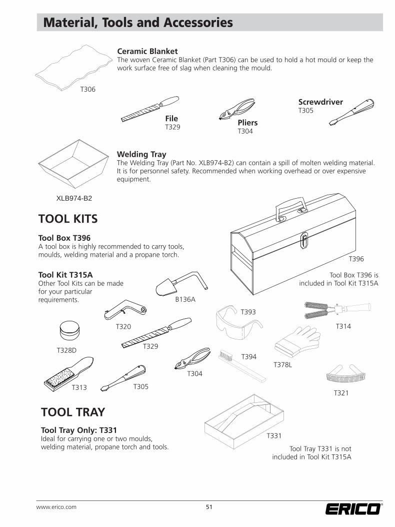
Ceramic BlanketThe woven Ceramic Blanket (Part T306) can be used to hold a hot mould or keep thework surface free of slag when cleaning the mould.
FileT329
T306
T328D
T320
B136A
T329
T313 T305
T304
T393
T378LT394
T321
T314
T396
XLB974-B2
PliersT304
ScrewdriverT305
Welding TrayThe Welding Tray (Part No. XLB974-B2) can contain a spill of molten welding material.It is for personnel safety. Recommended when working overhead or over expensiveequipment.
TOOL KITS
TOOL TRAY
Tool Box T396A tool box is highly recommended to carry tools,moulds, welding material and a propane torch.
Tool Kit T315AOther Tool Kits can be madefor your particularrequirements.
Tool Tray Only: T331Ideal for carrying one or two moulds,welding material, propane torch and tools.
Tool Box T396 is included in Tool Kit T315A
T331
Tool Tray T331 is notincluded in Tool Kit T315A
51www.erico.com
Reference Material
WARNING ERICO products shall be installed and used only as indicated in ERICO's product instruction sheets and training materials. Instruction sheets are available at www.erico.com and from your ERICO customer service representative. Improper installation, misuse, misapplication or other failure to completely follow ERICO's instructions and warnings may cause product malfunction, property damage, serious bodily injury and death.
WARRANTYERICO products are warranted to be free from defects in material and workmanship at the time of shipment. NO OTHER WARRANTY, WHETHER EXPRESS OR IMPLIED (INCLUDING ANY WARRANTY OF MERCHANTABILITY OR FITNESS FOR APARTICULAR PURPOSE), SHALL EXIST IN CONNECTION WITH THE SALE OR USE OF ANY ERICO PRODUCTS. Claims for errors, shortages, defects or nonconformities ascertainable upon inspection must be made in writing within 5 days afterBuyer's receipt of products. All other claims must be made in writing to ERICO within 6 months from the date of shipment or transport. Products claimed to be nonconforming or defective must, upon ERICO's prior written approval in accordance with its standard terms and procedures governing returns, promptly be returned to ERICO for inspection. Claims not made as provided above and within the applicable time period will be barred. ERICO shall in no event be responsible if the products have not been stored or used in accordance with its specifications and recommended procedures. ERICO will, at its option, either repair or replace nonconforming or defective products for which it is responsible orreturn the purchase price to the Buyer. THE FOREGOING STATES BUYER'S EXCLUSIVE REMEDY FOR ANY BREACH OF ERICO WARRANTY AND FOR ANY CLAIM, WHETHER SOUNDING IN CONTRACT, TORT OR NEGLIGENCE, FOR LOSS ORINJURY CAUSED BY THE SALE OR USE OF ANY PRODUCT.
LIMITATION OF LIABILITYERICO excludes all liability except such liability that is directly attributable to the willful or gross negligence of ERICO's employees. Should ERICO be held liable its liability shall in no event exceed the total purchase price under the contract. ERICOSHALL IN NO EVENT BE RESPONSIBLE FOR ANY LOSS OF BUSINESS OR PROFITS, DOWNTIME OR DELAY, LABOR, REPAIR OR MATERIAL COSTS OR ANY SIMILAR OR DISSIMILAR CONSEQUENTIAL LOSS OR DAMAGE INCURRED BY BUYER.
OTHER SPECIALIZED APPLICATION CATALOGS, APPLICATIONS, BULLETINS ANDTECHNICAL INFORMATION
A1L ERITECH® STATIC GROUNDING CONNECTIONS
A4G CADWELD® SUBSTATION GROUNDINGNumerous applications and guidelines for grounding electrical supply station (substations).
A7D CADWELD INSTALLERS AND INSPECTORS GUIDEA guide for installation and inspection of CADWELD® exothermically welded connections.
A9E CADWELD CONTRACTOR TIPSIdeal for contractors – How to save time and make the installation easy.
CA1A CADWELD CATHODIC PROTECTION CONNECTIONS CATALOG
TRAINING VIDEOS
E469D CADWELD®/CADWELD® PLUS CD
Product # Description
G157LT99 Practical Guide to Electrical Grounding
52 www.erico.com
ERICO® Facility Electrical Protection Literature
Facility Electrical Protection Solutions BrochureDiscusses effective facility electrical protection. The catalog details the ERICO® Six PointPlan of Protection and goes on to cover lightning protection, grounding, bonding andsurge protection in depth. Products and detailed drawings are included, as are industriesto which the technologies are most applicable.
ERITECH® Lightning Protection CatalogsERITECH® SYSTEM 1000 Lightning Protection Products catalog highlights the ERITECH®
INTERCEPTOR SI System and Components. This is an Early Streamer Emissions (ESE) AirTerminal Design including air terminals, masts, bases and accessories.
ERITECH® SYSTEM 2000 Lightning Protection Products catalog highlights products usedin conventional lightning protection. Products detailed include conductors, ground rodsand plates, clamps, splices, points and accessories.
ERITECH® SYSTEM 3000 Lightning Protection Products catalog details the activelightning protection process. Information on air terminals, downconductors and designsoftware is included.
ERITECH® Grounding Products CatalogDetails ERICO’s extensive offering of ground rods and accessories, ground mesh andmats, signal reference grids, ground bars, ground receptacles, transient earth clamps,ground enhancement materials, and other grounding materials.
CADWELD® Welded Electrical Connections CatalogCovers the range of hardware required to make a CADWELD connection as well asdetailed ordering information for molds, weld materials, fence and gate jumpers and thesmokeless CADWELD® EXOLON process.
CRITEC® Surge Protection Products Catalog Details the extensive range of CRITEC Surge Protection Devices for industries such ascommercial & industrial, process control & automation and telecommunications. Itincludes information on AC protection products, data control and signal protectionproducts, as well as point-of-use protection products.
53www.erico.com

AutoCad is a registered trademark of Autodesk, Inc.Copperweld is a registered trademark of Copperweld CorporationIEEE is a registered trademark of The Institute of Electrical and Electronics Engineers, Inc.NEC is a registered trademark of National Fire Protection Association, Inc.NEMA is a registered trademark of National Electrical Manufacturers AssociationSurefire is a registered trademark of Newell-Rubbermade Company
Copyright ©2009 ERICO International Corporation. All rights reserved.CADDY, CADWELD, CRITEC, ERICO, ERIFLEX, ERITECH, and LENTON are registered trademarks of ERICO International Corporation. E524C-ASEN E981CT09ASEN 0065M9
AUSTRALIAPhone 1800-263-508Fax 1800-423-091
BELGIUMPhone 0800-757-48Fax 0800-757-60
CANADAPhone +1-800-677-9089Fax +1-800-677-8131
CHILEPhone +56-2-370-2908Fax +56-2-369-5657
DENMARKPhone 808-89-373Fax 808-89-372
FRANCEPhone 0800-901-793Fax 0800-902-024
GERMANYPhone 0-800-189-0272Fax 0-800-189-0274
HONG KONGPhone +852-2764-8808Fax +852-2764-4486
HUNGARYPhone 06-800-16538Fax +31-13-583-5406
INDONESIAPhone +62-21-575-0941Fax +62-21-575-0942
ITALYPhone 800-870-938Fax 800-873-935
MEXICOPhone +52-55-5260-5991Fax +52-55-5260-3310
NETHERLANDSPhone +31-13-583-5400Fax +31-13-583-5499
NORWAYPhone 800-100-73Fax 800-100-66
SINGAPOREPhone +65-6-268-3433Fax +65-6-268-1389
SPAINPhone 900-993-154Fax 900-993-106
SWEDENPhone 020-790-908Fax 020-798-964
SWITZERLANDPhone 0800-55-86-97Fax 0800-55-96-15
THAILANDPhone +66-2-267-5776Fax +66-2-636-6988
UNITED KINGDOMPhone +0808-2344-670Fax +0808-2344-676
UNITED STATESPhone +1-440-248-0100Fax +1-440-248-0723
POLANDPhone +48-71-349-04-60Fax +48-71-349-04-61
BRAZILPhone +55-11-3623-4333Fax +55-11-3621-4066
www.erico.com
CHINAPhone +86-21-3430-4878 Fax +86-21-5831-8177
UNITED ARABEMIRATESPhone +971-4-881-7250Fax +971-4-881-7270