CADILLAC ESCALADE 2000-2006 - KW suspensionsdocs.kwsuspension.de/ealsd50063001.pdf ·...
46
50063001 Cadillac Escalade 5/06 1 A Division of KW automotive North America, Inc CADILLAC ESCALADE 2000-2006 LSD INSTALLATION
Transcript of CADILLAC ESCALADE 2000-2006 - KW suspensionsdocs.kwsuspension.de/ealsd50063001.pdf ·...

50063001 Cadillac Escalade 5/06 1 A Division of KW automotive North America, Inc
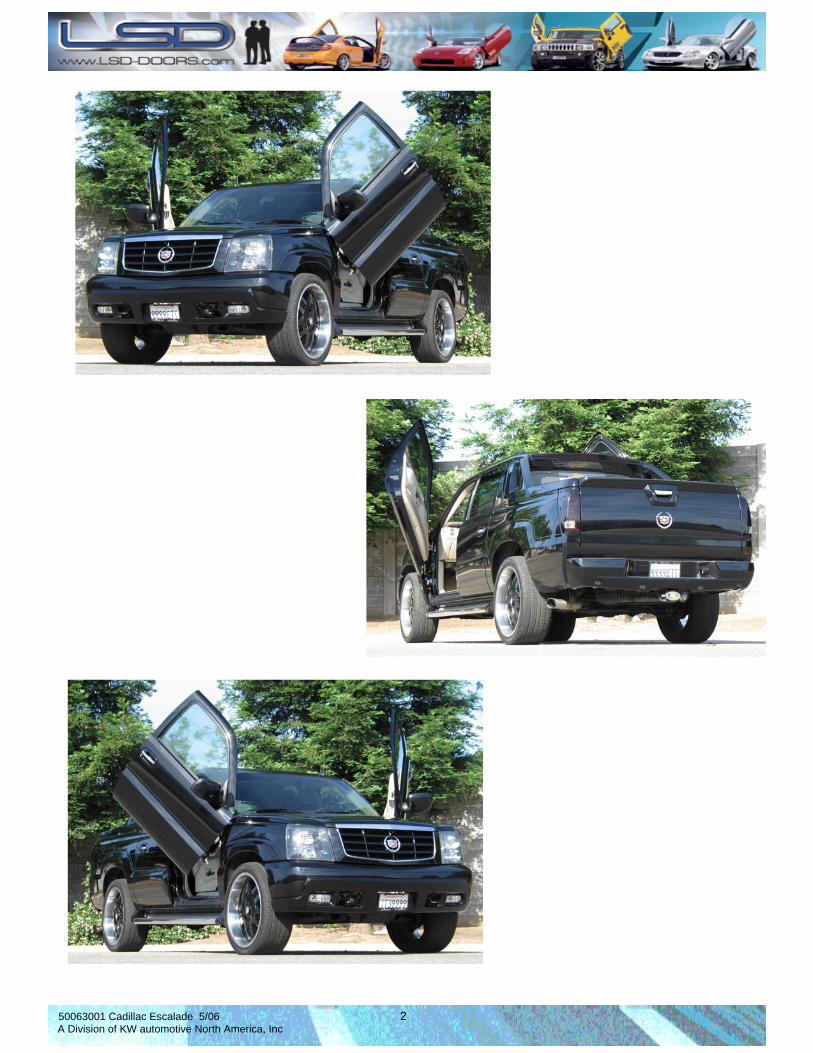
CADILLAC ESCALADE 2000-2006
LSD INSTALLATION
50063001 Cadillac Escalade 5/06 2 A Division of KW automotive North America, Inc

50063001 Cadillac Escalade 5/06 3 A Division of KW automotive North America, Inc
INSTALLATION INTRODUCTION 1. REMOVING THE FENDER, DOORS FROM THE A-PILLAR AND DISCONNECTING THE
WIRE HARNESS @ THE DOOR JAM 2. REMOVING THE EXISTING DOOR HINGES FROM THE DOORS; TOP AND BOTTOM. 3. MODIFYING THE INTERNAL FENDER AREAS FOR THE HINGE CLEARANCE. 4. MODIFYING THE ELECTRICAL HARNESS. 5. INSTALLING THE GROUND PLATE TO THE A-PILLAR AND THE SWING ARM TO THE DOOR. 6. HANGING AND ALIGNING THE VEHICLE DOORS. 7. INSTALLING THE FENDER AND CHECKING FOR CLEARANCE. 8. REMOVE FENDER AND ROUTE THE WIRING. 9. RE-INSTALL FENDER AND CHECK FOR CLEARANCE. 10. JOB COMPLETE!

50063001 Cadillac Escalade 5/06 4 A Division of KW automotive North America, Inc
Installation Instructions LamboStyleDoors (The instructions are to be used as a reference only. Please repeat steps for both doors.)
Pre-installation check list:
•Battery disconnected •Front bumper removal •Front fender removal •Vehicle must be accident free •Vehicle must have inner fender cover
Preparations: (Disassemble parts according to the vehicle manufacturers’ specifications)
• Disassemble the door stopper • Disconnect the wire harness between the chassis and the door (remove the harness from the door interior
when necessary) • Disassemble the door. For this procedure, remove the pin between the hinges. • Modify the hinges at the A-pillar and on the door (please see enclosure “modifying the hinges”, pages 9-
16 • Extend the factory door wire harness with the enclosed wire harness extension kit. (See enclosed “wire harness extension, page 19 ) • Modify the fender (See enclosed “modifying the fender”, page 21 ) • Relocate the door lock vacuum case (when necessary). (e.g. from the passenger’s side inner fender to the engine compartment) • Modify the windshield washer reservoir (when necessary).
50063001 Cadillac Escalade 5/06 5 A Division of KW automotive North America, Inc
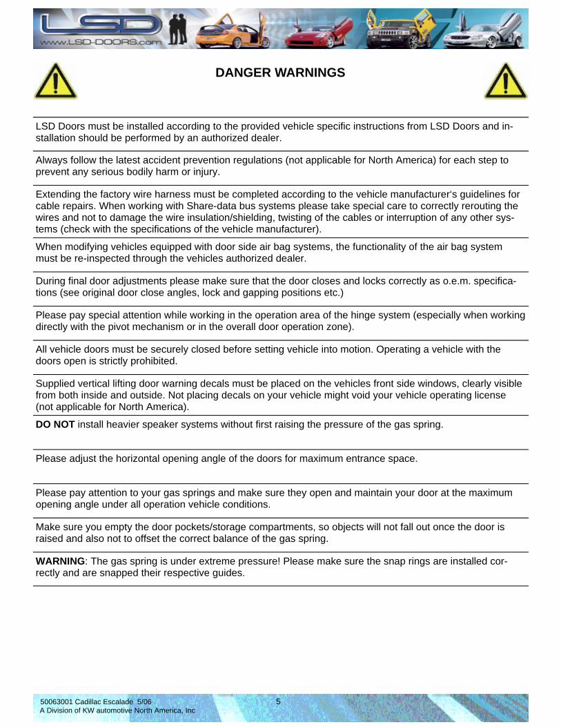
LSD Doors must be installed according to the provided vehicle specific instructions from LSD Doors and in-stallation should be performed by an authorized dealer.
Always follow the latest accident prevention regulations (not applicable for North America) for each step to prevent any serious bodily harm or injury.
Extending the factory wire harness must be completed according to the vehicle manufacturer‘s guidelines for cable repairs. When working with Share-data bus systems please take special care to correctly rerouting the wires and not to damage the wire insulation/shielding, twisting of the cables or interruption of any other sys-tems (check with the specifications of the vehicle manufacturer).
When modifying vehicles equipped with door side air bag systems, the functionality of the air bag system must be re-inspected through the vehicles authorized dealer.
During final door adjustments please make sure that the door closes and locks correctly as o.e.m. specifica-tions (see original door close angles, lock and gapping positions etc.)
Please pay special attention while working in the operation area of the hinge system (especially when working directly with the pivot mechanism or in the overall door operation zone).
All vehicle doors must be securely closed before setting vehicle into motion. Operating a vehicle with the doors open is strictly prohibited.
Supplied vertical lifting door warning decals must be placed on the vehicles front side windows, clearly visible from both inside and outside. Not placing decals on your vehicle might void your vehicle operating license (not applicable for North America).
DO NOT install heavier speaker systems without first raising the pressure of the gas spring.
Please adjust the horizontal opening angle of the doors for maximum entrance space.
Please pay attention to your gas springs and make sure they open and maintain your door at the maximum opening angle under all operation vehicle conditions.
Make sure you empty the door pockets/storage compartments, so objects will not fall out once the door is raised and also not to offset the correct balance of the gas spring.
WARNING: The gas spring is under extreme pressure! Please make sure the snap rings are installed cor-rectly and are snapped their respective guides.
DANGER WARNINGS

50063001 Cadillac Escalade 5/06 6 A Division of KW automotive North America, Inc
An additional inside support handle must be installed to solve the issue of possible difficulty of griping the door, when raising and lowering your door from your seated position.
If there are white lights on your door, these must be made ineffective, e. g. taking of the bulb and bulb holder according to fig. 5.22 ECE-law no. 48.
After mounting the LSD hinge system you must reinstall your OEM inner fender covers to keep your LSD hinges free from debris and corrosion.
You must have an authorized workshop check that the central locking system (if equipped) is working prop-erly.
You must have an authorized workshop check the functionality of all systems, switches and components (including: loudspeakers, alarm system, CAN data bus systems, window lifts, crash-sensor, memory seat ad-justment, mirror adjustment and heating, etc. if equipped).
While adjusting the door please take special care to position it in the matching door frame as not to cause any damages to paint etc.
In case any chassis modifications were performed, please use the supplied chassis glue (if required for spe-cific application) to seal any openings on the A-pillar or doors (make sure panels are free from grease and dust before applying chassis glue for a superior water tight seal).
NOTE: please be aware your car might have different factory installed equipment from our tested R&D vehi-cle, in this case please contact your LSD dealer to order higher or lower power gas damper units (an addi-tional cost may apply).
Please note that the power of the gas dampers may fluctuate due to ambient temperature variations, the opening and closing forces may also differ according to damper manufacturers specifications (warranty claims will only be honored if there’s an internal defect or an error in production).
All LSD hinges come with a protective oil coating, please remove coating and then apply the included PSK spray for superior sealing of the finish.
If any body work is performed, use Corrosion prevention methods according to the vehicle manufactures specifications.
Updated installation instructions can be found on www.lsd-doors.com (guide notes subject to change without notice).
A second person makes the work much easier. Please instruct the second person before start work-ing.
It is recommended to keep your LSD door hinges maintained on a regular basis for a lifetime of trouble free operation.
General installation instructions:
! Attention notice:

50063001 Cadillac Escalade 5/06 7 A Division of KW automotive North America, Inc
- After washing the vehicle, open the doors and check to see that all pivot points are properly greased
- Every three months, open doors and check to see that all pivot points are properly greased
- If the vehicle is subject to a harsh environment, such as salt or sand, it is critical that all pivot points stay lubricated, especially if the doors are being used frequently, open doors and check to see that all pivot points are greased properly
General Lubrication Information In order for the LSD Door System to function properly, adequate lubrication is essential at all pivot points on the system. Periodic lubricating of all pivot points is highly recommended on a consistent basis. This helps in the life of all bearings involved. Listed below are helpful hints of when to lubricate:

50063001 Cadillac Escalade 5/06 8 A Division of KW automotive North America, Inc
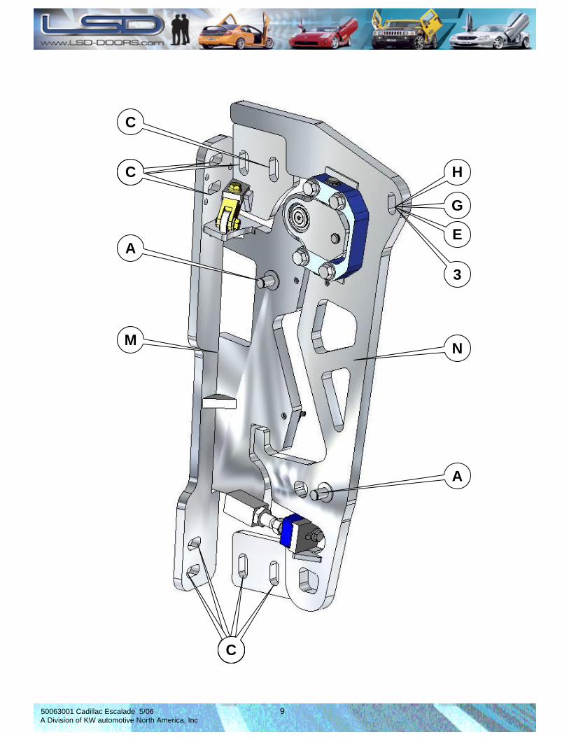
1x A 5X B 8x C 2x D
Snap ring Cable ties Serrated bolt M8 Rubber Grommet
2x E 3x F 1x G 1x H
Distance Spacer Cable clip Hexagon bolt Threaded rivet insert M8
1x I 1x J 1x K 3x L
Hexagon bolt Chassis glue Gas Damper Shim
1x M 1x N 2x O 2x P
LSD Swing Arm LSD Ground Plate Flat washer 15x5,3 Cover plate
HARDWARE LIST ( per vehicle side)
2x Q
LSD Warning notice
2x R
Escalade Door Plate
2x S
Shim Roller Mount
50063001 Cadillac Escalade 5/06 9 A Division of KW automotive North America, Inc
H
G
E
3
H H C
C
A
A
N M
A A A C

50063001 Cadillac Escalade 5/06 10 A Division of KW automotive North America, Inc
ORIGINAL EQUIPMENT CHASSIS HINGE REMOVAL MODIFICATION
IMPORTANT NOTE: The following instructions give, in sequential order, a step-by-step procedure to mini-mize any installation difficulty that may occur. By skipping steps, un-necessary problems can arise during the installation process. The photos below shows areas on the O.E.M hinges that need to be marked for modifi-cation, (BEFORE), prior to beginning the modification process.
Follow STEP 1 on page 11 and 12 for a detail look on how to properly remove the O.E.M. hinges on the A-Pillar. Follow the same procedure for the door hinge removal. See page 12 for a detail look.
BEFORE BEFORE
A-PILLAR DOOR
50063001 Cadillac Escalade 5/06 11 A Division of KW automotive North America, Inc
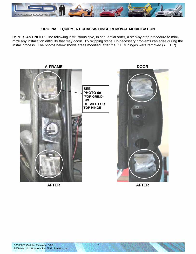
ORIGINAL EQUIPMENT CHASSIS HINGE REMOVAL MODIFICATION
IMPORTANT NOTE: The following instructions give, in sequential order, a step-by-step procedure to mini-mize any installation difficulty that may occur. By skipping steps, un-necessary problems can arise during the install process. The photos below shows areas modified, after the O.E.M hinges were removed (AFTER).
AFTER AFTER
A-FRAME DOOR
SEE PHOTO 6e (FOR GRIND-ING DETAILS FOR TOP HINGE

50063001 Cadillac Escalade 5/06 12 A Division of KW automotive North America, Inc
STEP 1 ORIGINAL EQUIPMENT CHASSIS HINGE REMOVAL MODIFICATION NOTE: Photos 1 thru 4 depicts the A-Pillar hinge areas 1a. Hinges are prepped for removal by marking what needs to be removed initially (Photo 1). Using a reciprocating saw, remove the OEM HINGES, top and bottom from the chassis (Photo 2,3) 1b. Hinge plates are ready to be ground smooth (Photo 4). 1c. Grind the face of the A-Pillar hinge plate smooth (Photo 5). 1d. Using a square, its important to maintain a flat surface after grinding (Photo 6).
PHOTO 1 PHOTO 2
PHOTO 4
PHOTO 3
PHOTO 5
PHOTO 6
STRAIGHT EDGE
HINGE PLATE A-PILLAR

50063001 Cadillac Escalade 5/06 13 A Division of KW automotive North America, Inc
STEP 1 ORIGINAL EQUIPMENT CHASSIS HINGE REMOVAL MODIFICATION –cont’d- 1f. Its important to note that as you begin to grind smooth the edges (Photo 5) that were just cut by removing the hinge mounts, that the face of the hinge plate stays smooth. Periodically check the surface for a true flat finish by using a straight edge (Photo 6). 1g. Any un-even surface on the A-Pillar hinge plate will cause the new door hinge to not properly mount to the chassis door frame. REPEAT THE PROCESS FOR THE DOOR 1h. Once you have marked the areas of the hinge that are going to be removed, with a cut ting tool (Photo 6a, 6b), remove both hinges, as shown. 1i. Grind the face of the door hinge smooth (Photo 6c) 1j. Using a square, its important to maintain a flat surface after grinding (Photo 6d)
PHOTO 6a PHOTO 6b
PHOTO 6c PHOTO 6d

50063001 Cadillac Escalade 5/06 14 A Division of KW automotive North America, Inc
STEP 1 ORIGINAL EQUIPMENT CHASSIS HINGE REMOVAL MODIFICATION –cont’d- MODIFICATION OF TOP HINGE PLATE (BOTH SIDES) For the Chevrolet Tahoe, the top hinge plates on both sides need to be shorten in height. This is needed for clearance for the swing arm. The steps below describes on how to do this. 1k. Once you have cut-off the hinge arms on the top plates, locate, from the center of the radius hole, 25mm down, scribe a horizontal line across the bottom of the hinge plate (Photo 6e). 1m. Use a cutting wheel. Cut the thickness of the hinge plate, down flush to the face of the A-Pillar. 1n. This is needed to allowance for clearance of the swing arm.
25mm
PHOTO 6e
A-PILLAR FACE

50063001 Cadillac Escalade 5/06 15 A Division of KW automotive North America, Inc
CREATING NEW MOUNTING POINTS ON THE A-FRAME FOR THE NEW DOOR HINGE
IMPORTANT NOTE: The following instructions give, in sequential order, a step-by-step procedure to mini-mize any installation difficulty that may occur. By skipping steps, un-necessary problems can arise during the install process. The photos below shows areas on the O.E.M A-Pillar hinges that need to be marked for new mounting points, (AFTER), removing the O/E.M. hinges (Photo 7). Also shown in DETAIL—AA, are the drill bit sizes needed for this procedure. From the hole punch, pilot hole drill bit, clearance drill bit, to the tap drill.
Follow STEP 2 on page 15 for a detail look on how to properly locate and drill the new mounting points.
DETAIL—AA
Shown in DETAIL-AA above, are the sizes of drill bits needed to create the mounting holes:
HOLE PUNCH
DRILL BIT (PILOT HOLE)
DRILL BIT
TAP
1 2 3 4 2m
m 6.8m
m
M8
1
2
3
4
PHOTO 7
TOP HOLES
BOT HOLES
50063001 Cadillac Escalade 5/06 16 A Division of KW automotive North America, Inc
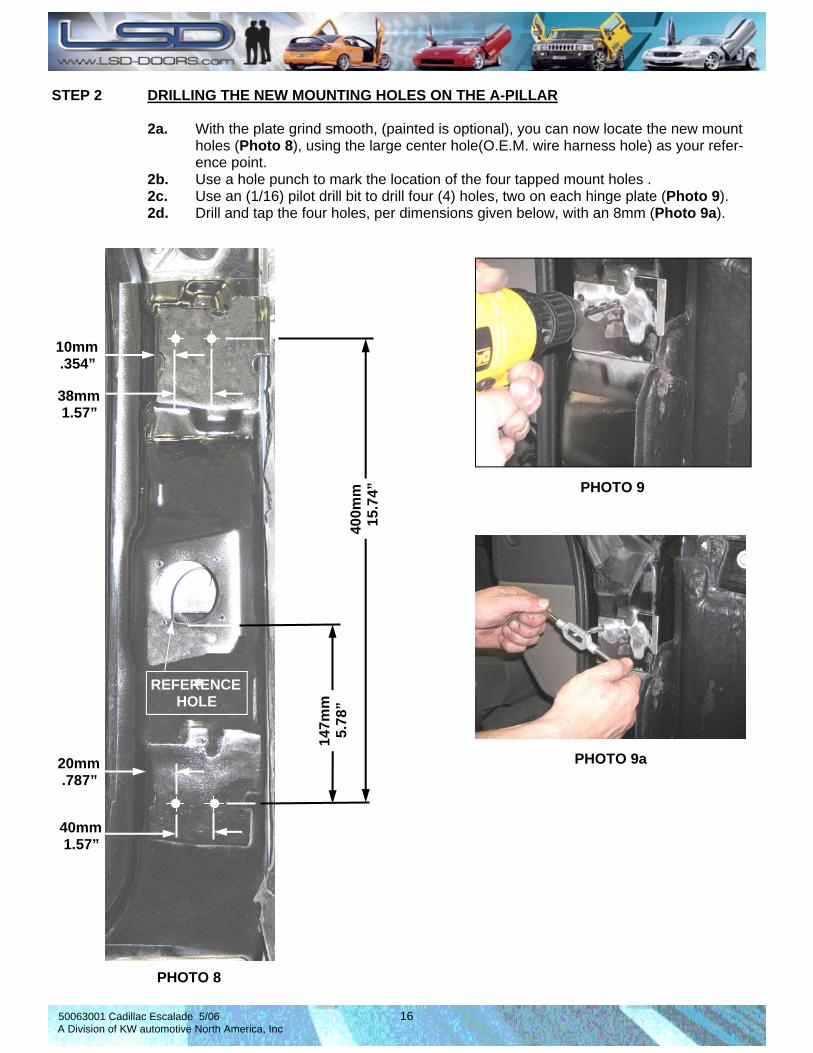
STEP 2 DRILLING THE NEW MOUNTING HOLES ON THE A-PILLAR 2a. With the plate grind smooth, (painted is optional), you can now locate the new mount holes (Photo 8), using the large center hole(O.E.M. wire harness hole) as your refer- ence point. 2b. Use a hole punch to mark the location of the four tapped mount holes . 2c. Use an (1/16) pilot drill bit to drill four (4) holes, two on each hinge plate (Photo 9). 2d. Drill and tap the four holes, per dimensions given below, with an 8mm (Photo 9a).
PHOTO 8
147m
m
5.7
8”
10mm .354”
38mm 1.57”
20mm .787”
40mm 1.57”
REFERENCE HOLE
PHOTO 9
PHOTO 9a
400m
m
15.
74”
50063001 Cadillac Escalade 5/06 17 A Division of KW automotive North America, Inc
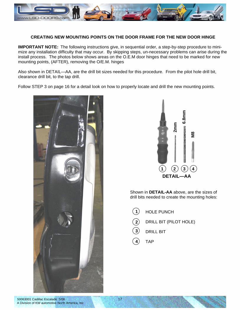
CREATING NEW MOUNTING POINTS ON THE DOOR FRAME FOR THE NEW DOOR HINGE
IMPORTANT NOTE: The following instructions give, in sequential order, a step-by-step procedure to mini-mize any installation difficulty that may occur. By skipping steps, un-necessary problems can arise during the install process. The photos below shows areas on the O.E.M door hinges that need to be marked for new mounting points, (AFTER), removing the O/E.M. hinges Also shown in DETAIL—AA, are the drill bit sizes needed for this procedure. From the pilot hole drill bit, clearance drill bit, to the tap drill.
Follow STEP 3 on page 16 for a detail look on how to properly locate and drill the new mounting points.
DETAIL—AA 1 2 3 4
2mm
6.8m
m
M8
Shown in DETAIL-AA above, are the sizes of drill bits needed to create the mounting holes:
HOLE PUNCH DRILL BIT (PILOT HOLE) DRILL BIT TAP
1
2
3
4

50063001 Cadillac Escalade 5/06 18 A Division of KW automotive North America, Inc
STEP 3 DRILLING THE NEW MOUNTING HOLES ON THE DOOR FRAME 3a. Locate the new mount holes, with a hole punch, marking the centers, according to the new dimensions 3b. Use an (M4) pilot drill bit to drill five (4) holes (Photo 10).
PHOTO 10
247mm
9.72”
29mm
1.10”
29mm
1.41”
50mm 1.96”
60mm 2.36”
367mm
14.4”

50063001 Cadillac Escalade 5/06 19 A Division of KW automotive North America, Inc
STEP 4 DIS-ASSEMBLING THE SWING ARM FROM THE GROUND PLATE 4a. Your new LSD Door Hinges have come assembled. 4b. As identified in (Photo 11), disassemble the swing arm from the ground plate. Un-bolt all four mounting bolts or allen-heads and remove completely.
PHOTO FOR REFERENCE ONLY
N
M
PHOTO 11

50063001 Cadillac Escalade 5/06 20 A Division of KW automotive North America, Inc
STEP 4 DIS-ASSEMBLING THE SWING ARM FROM THE GROUND PLATE 4c. As shown in photos below, disassemble the swing arm from the ground plate. Un-bolt all four mounting bolts or allen-heads and remove completely. Lay the pieces out next to each other.
ASSEMBLED
DIS-ASSEMBLED
50063001 Cadillac Escalade 5/06 21 A Division of KW automotive North America, Inc
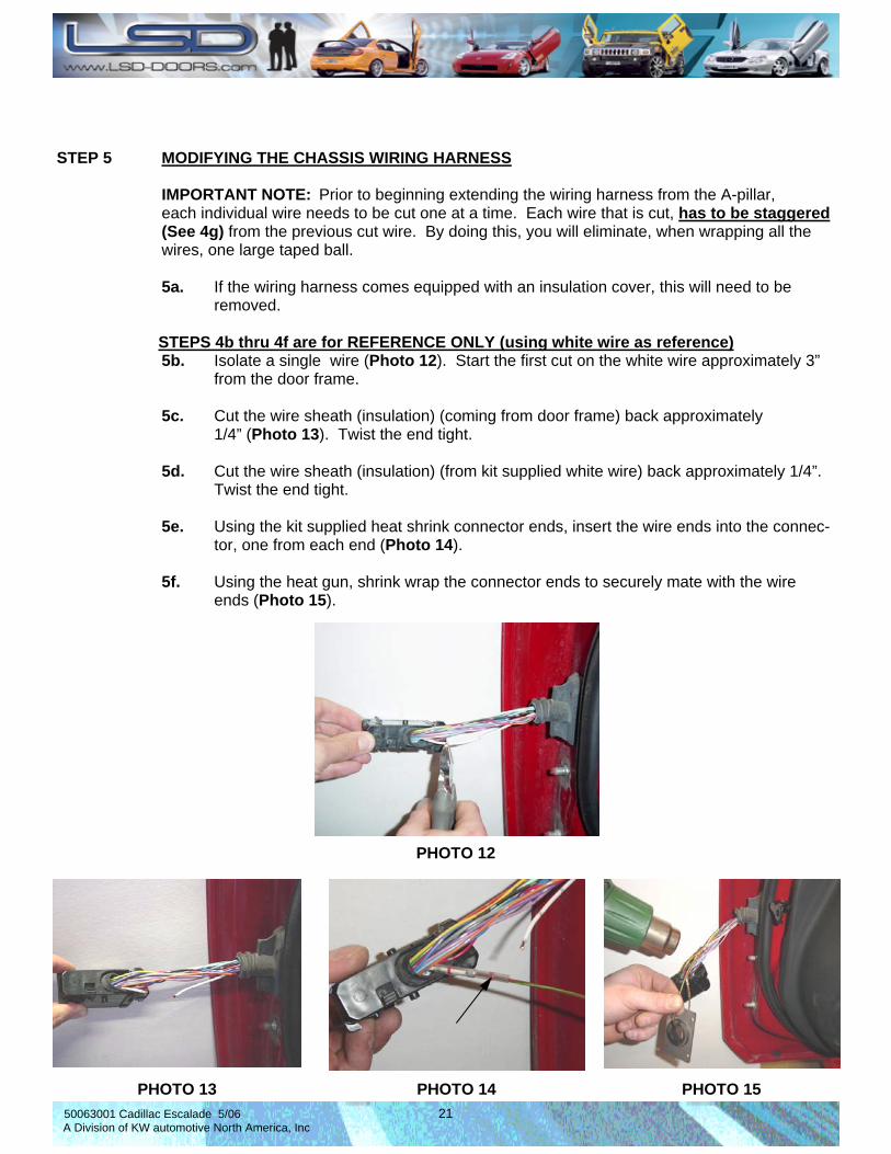
STEP 5 MODIFYING THE CHASSIS WIRING HARNESS IMPORTANT NOTE: Prior to beginning extending the wiring harness from the A-pillar, each individual wire needs to be cut one at a time. Each wire that is cut, has to be staggered (See 4g) from the previous cut wire. By doing this, you will eliminate, when wrapping all the wires, one large taped ball. 5a. If the wiring harness comes equipped with an insulation cover, this will need to be removed.
STEPS 4b thru 4f are for REFERENCE ONLY (using white wire as reference) 5b. Isolate a single wire (Photo 12). Start the first cut on the white wire approximately 3” from the door frame. 5c. Cut the wire sheath (insulation) (coming from door frame) back approximately 1/4” (Photo 13). Twist the end tight. 5d. Cut the wire sheath (insulation) (from kit supplied white wire) back approximately 1/4”. Twist the end tight. 5e. Using the kit supplied heat shrink connector ends, insert the wire ends into the connec- tor, one from each end (Photo 14). 5f. Using the heat gun, shrink wrap the connector ends to securely mate with the wire ends (Photo 15).
PHOTO 12
PHOTO 13 PHOTO 14 PHOTO 15
50063001 Cadillac Escalade 5/06 22 A Division of KW automotive North America, Inc
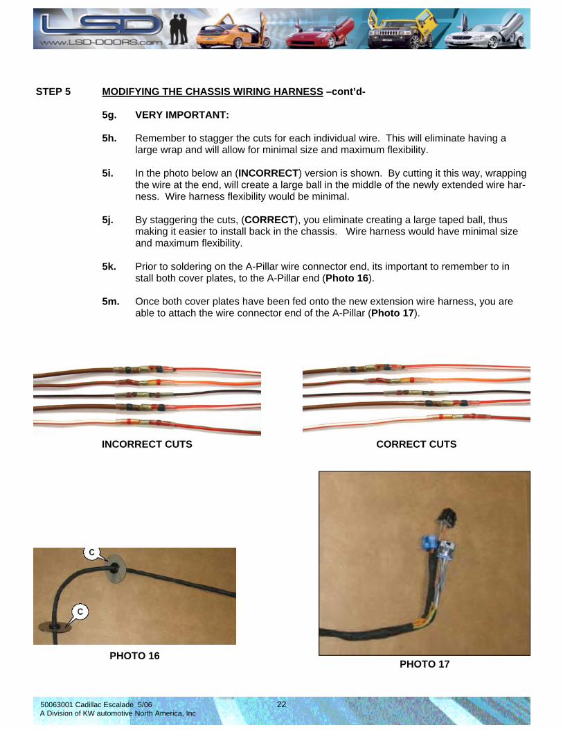
STEP 5 MODIFYING THE CHASSIS WIRING HARNESS –cont’d- 5g. VERY IMPORTANT: 5h. Remember to stagger the cuts for each individual wire. This will eliminate having a large wrap and will allow for minimal size and maximum flexibility. 5i. In the photo below an (INCORRECT) version is shown. By cutting it this way, wrapping the wire at the end, will create a large ball in the middle of the newly extended wire har- ness. Wire harness flexibility would be minimal. 5j. By staggering the cuts, (CORRECT), you eliminate creating a large taped ball, thus making it easier to install back in the chassis. Wire harness would have minimal size and maximum flexibility. 5k. Prior to soldering on the A-Pillar wire connector end, its important to remember to in stall both cover plates, to the A-Pillar end (Photo 16). 5m. Once both cover plates have been fed onto the new extension wire harness, you are able to attach the wire connector end of the A-Pillar (Photo 17).
INCORRECT CUTS CORRECT CUTS
PHOTO 16 PHOTO 17
50063001 Cadillac Escalade 5/06 23 A Division of KW automotive North America, Inc
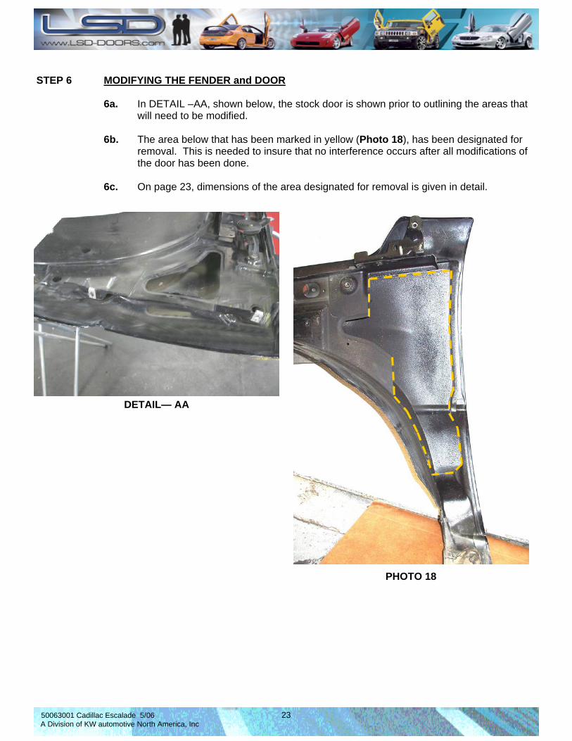
STEP 6 MODIFYING THE FENDER and DOOR 6a. In DETAIL –AA, shown below, the stock door is shown prior to outlining the areas that will need to be modified. 6b. The area below that has been marked in yellow (Photo 18), has been designated for removal. This is needed to insure that no interference occurs after all modifications of the door has been done. 6c. On page 23, dimensions of the area designated for removal is given in detail.
PHOTO 18
DETAIL— AA
50063001 Cadillac Escalade 5/06 24 A Division of KW automotive North America, Inc
640m
m
(25.
19”)
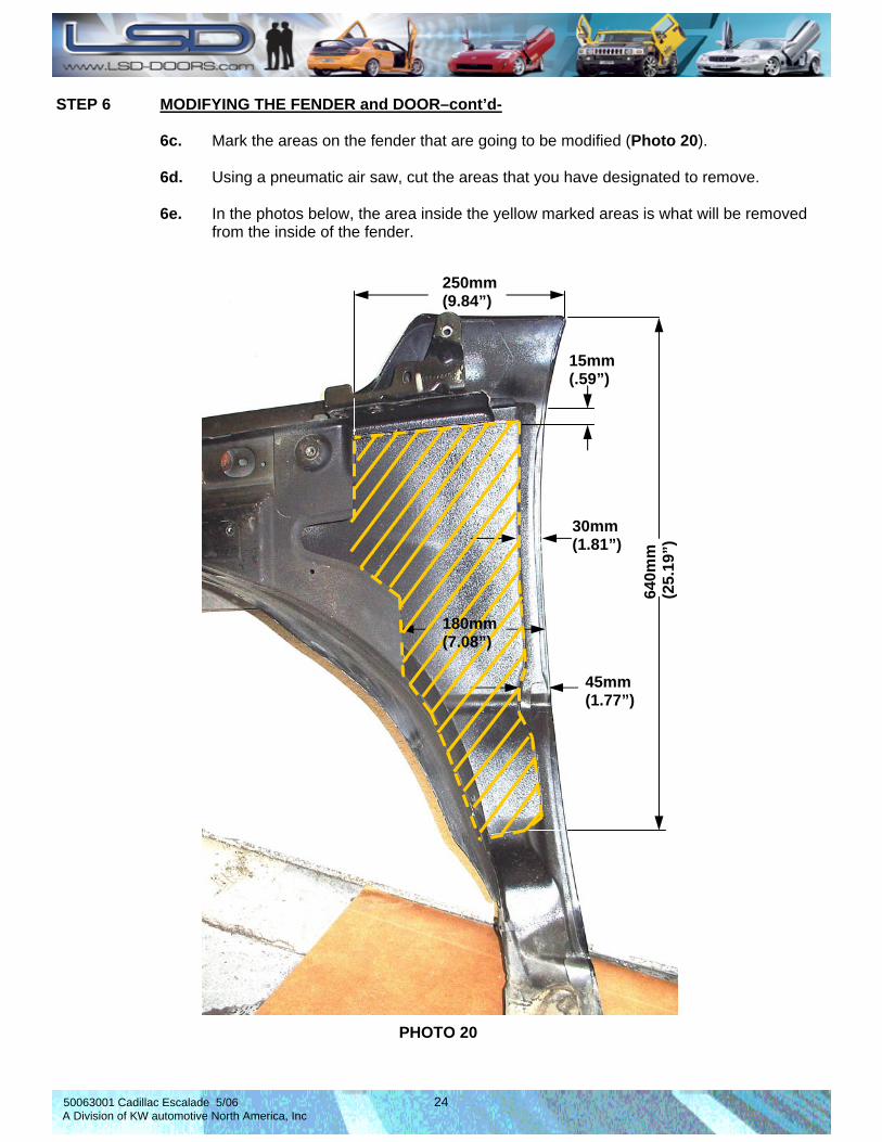
250mm (9.84”)
15mm (.59”)
30mm (1.81”)
45mm (1.77”)
STEP 6 MODIFYING THE FENDER and DOOR–cont’d- 6c. Mark the areas on the fender that are going to be modified (Photo 20). 6d. Using a pneumatic air saw, cut the areas that you have designated to remove. 6e. In the photos below, the area inside the yellow marked areas is what will be removed from the inside of the fender.
PHOTO 20
180mm (7.08”)
50063001 Cadillac Escalade 5/06 25 A Division of KW automotive North America, Inc
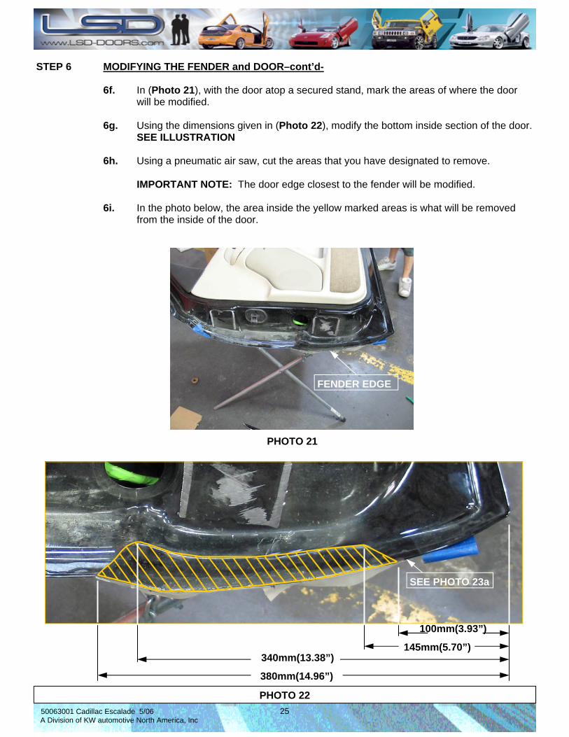
STEP 6 MODIFYING THE FENDER and DOOR–cont’d- 6f. In (Photo 21), with the door atop a secured stand, mark the areas of where the door will be modified. 6g. Using the dimensions given in (Photo 22), modify the bottom inside section of the door. SEE ILLUSTRATION 6h. Using a pneumatic air saw, cut the areas that you have designated to remove. IMPORTANT NOTE: The door edge closest to the fender will be modified. 6i. In the photo below, the area inside the yellow marked areas is what will be removed from the inside of the door.
PHOTO 21
380mm(14.96”)
340mm(13.38”)
100mm(3.93”)
145mm(5.70”)
PHOTO 22
FENDER EDGE
SEE PHOTO 23a
50063001 Cadillac Escalade 5/06 26 A Division of KW automotive North America, Inc
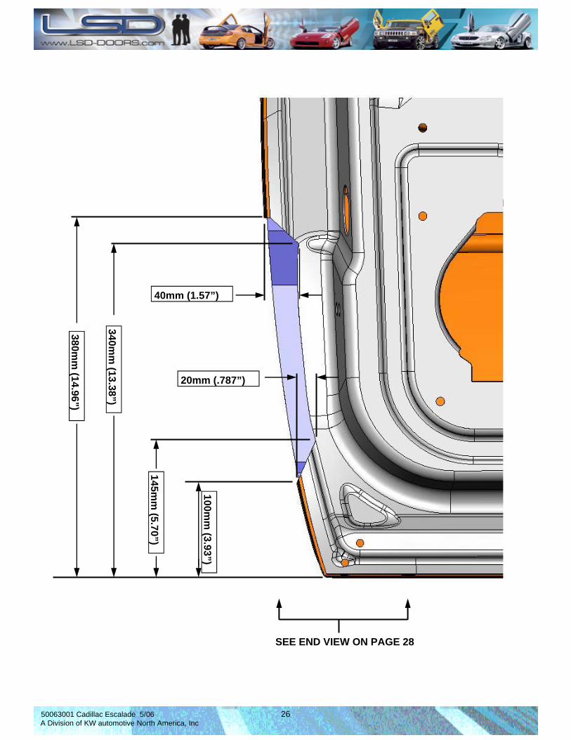
380mm
(14.96”)
340mm
(13.38”)
145mm
(5.70”)
100mm
(3.93”)
40mm (1.57”)
20mm (.787”)
SEE END VIEW ON PAGE 28
50063001 Cadillac Escalade 5/06 27 A Division of KW automotive North America, Inc
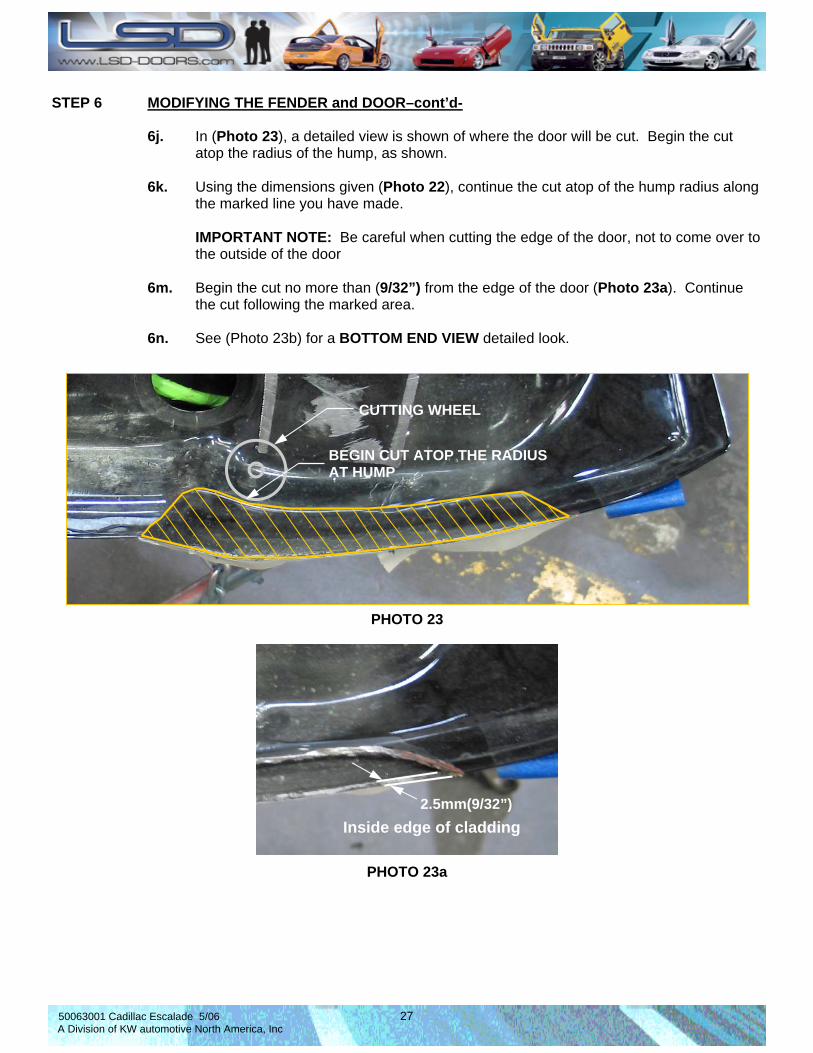
STEP 6 MODIFYING THE FENDER and DOOR–cont’d- 6j. In (Photo 23), a detailed view is shown of where the door will be cut. Begin the cut atop the radius of the hump, as shown. 6k. Using the dimensions given (Photo 22), continue the cut atop of the hump radius along the marked line you have made. IMPORTANT NOTE: Be careful when cutting the edge of the door, not to come over to the outside of the door 6m. Begin the cut no more than (9/32”) from the edge of the door (Photo 23a). Continue the cut following the marked area. 6n. See (Photo 23b) for a BOTTOM END VIEW detailed look.
BEGIN CUT ATOP THE RADIUS AT HUMP
CUTTING WHEEL
PHOTO 23
2.5mm(9/32”)
PHOTO 23a
Inside edge of cladding

50063001 Cadillac Escalade 5/06 28 A Division of KW automotive North America, Inc
CUT ALONG INSIDE OF CLADDING
BO T T O M E N D V I E W
IMPORTANT NOTE: To not damage the outer part of the door, cut along the edge of the inside of the cladding using the directions given on page 26.
50063001 Cadillac Escalade 5/06 29 A Division of KW automotive North America, Inc
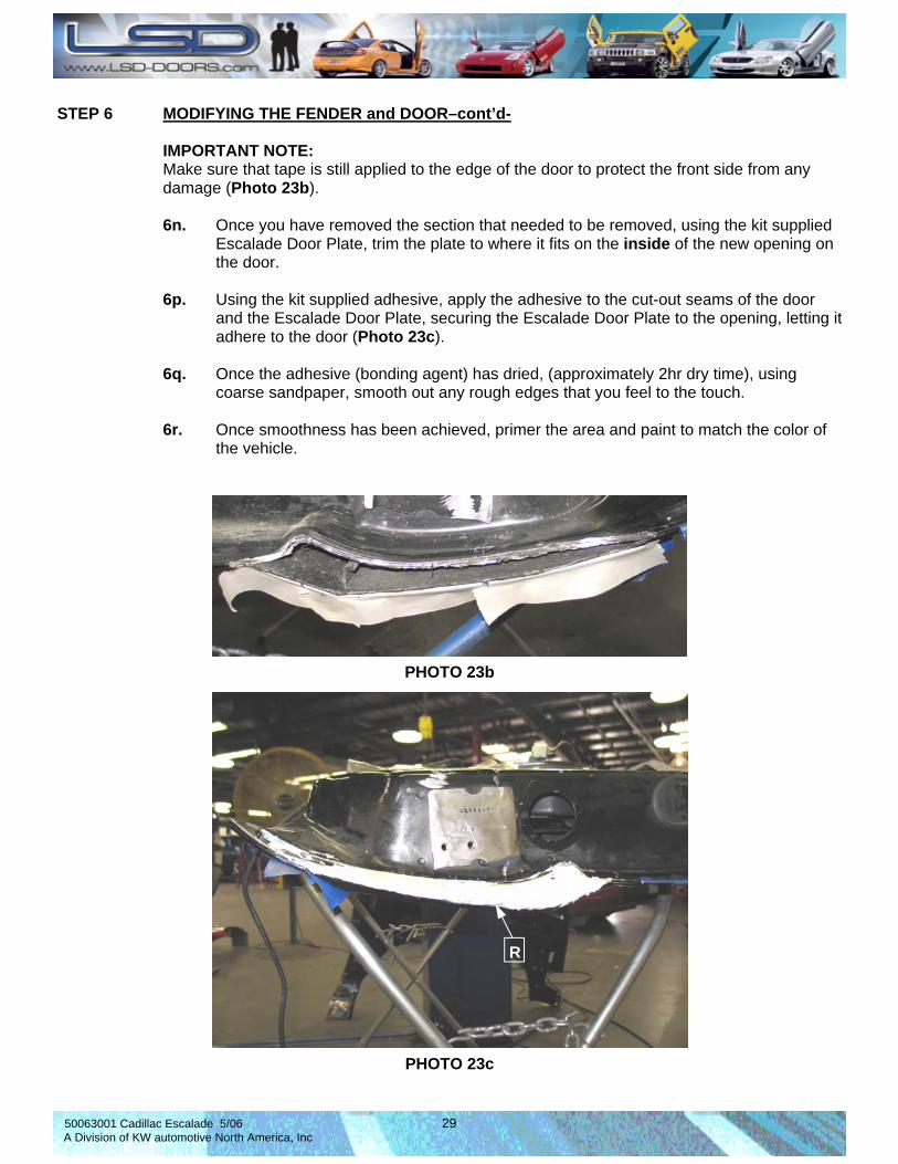
STEP 6 MODIFYING THE FENDER and DOOR–cont’d- IMPORTANT NOTE: Make sure that tape is still applied to the edge of the door to protect the front side from any damage (Photo 23b). 6n. Once you have removed the section that needed to be removed, using the kit supplied Escalade Door Plate, trim the plate to where it fits on the inside of the new opening on the door. 6p. Using the kit supplied adhesive, apply the adhesive to the cut-out seams of the door and the Escalade Door Plate, securing the Escalade Door Plate to the opening, letting it adhere to the door (Photo 23c). 6q. Once the adhesive (bonding agent) has dried, (approximately 2hr dry time), using coarse sandpaper, smooth out any rough edges that you feel to the touch. 6r. Once smoothness has been achieved, primer the area and paint to match the color of the vehicle.
PHOTO 23b
PHOTO 23c
R
50063001 Cadillac Escalade 5/06 30 A Division of KW automotive North America, Inc
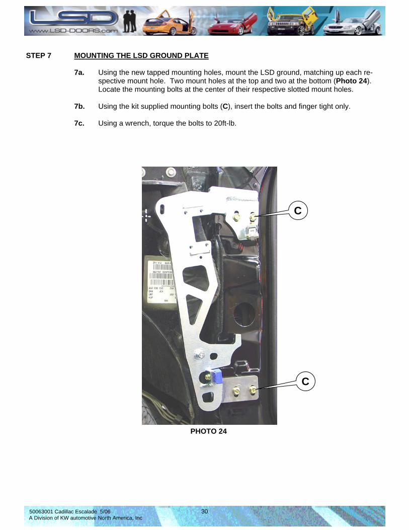
STEP 7 MOUNTING THE LSD GROUND PLATE 7a. Using the new tapped mounting holes, mount the LSD ground, matching up each re- spective mount hole. Two mount holes at the top and two at the bottom (Photo 24). Locate the mounting bolts at the center of their respective slotted mount holes. 7b. Using the kit supplied mounting bolts (C), insert the bolts and finger tight only. 7c. Using a wrench, torque the bolts to 20ft-lb.
PHOTO 24
C
C
50063001 Cadillac Escalade 5/06 31 A Division of KW automotive North America, Inc
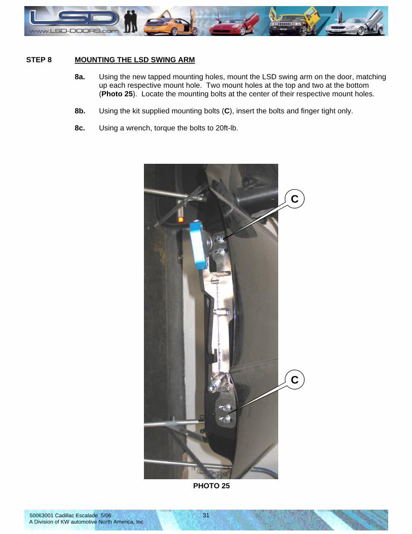
STEP 8 MOUNTING THE LSD SWING ARM 8a. Using the new tapped mounting holes, mount the LSD swing arm on the door, matching up each respective mount hole. Two mount holes at the top and two at the bottom (Photo 25). Locate the mounting bolts at the center of their respective mount holes. 8b. Using the kit supplied mounting bolts (C), insert the bolts and finger tight only. 8c. Using a wrench, torque the bolts to 20ft-lb.
PHOTO 25
C
C

50063001 Cadillac Escalade 5/06 32 A Division of KW automotive North America, Inc
STEP 9 MOUNTING THE DOOR TO THE A-FRAME IMPORTANT NOTE: THIS STEP SHOULD BE DONE WITHOUT THE GAS SPRING IN- STALLED 9a. Place the door back on the vehicle and close the door completely. 9a. Install the MAGICSTIK into position (Photo 26) Initially, this is done for mounting pur- poses only, using the MAGICSTIK as a guide. 9b. Lifting the door into position, guide the MAGICSTIK into its mating block (Photo 27), manually holding the door there, as close to the closed position as possible. 9c. Attach the swing arm to the ground plate with the four (4) kit supplied bolts and adjust the door via moving the swing arm adjustable plate connection mount with the horizon- tal door gap adjuster in the right or left direction until the gap measurement is like the original (Photo 28).
ADJUSTING THE DOOR HEIGHT 9d. Adjustment height of the door is by moving the chassis plate (N) vertically. Make sure the mounting hardware (C) is loosened to be able to do this. 9e. Adjustment depth of the door is by moving the door horizontal. Make sure the mount- ing hardware (C) is loosened to be able to do this.
PHOTO 26
PHOTO 27
PHOTO 28
IMPORTANT NOTE: Torque mounting bolt to 10ft-lb.
50063001 Cadillac Escalade 5/06 33 A Division of KW automotive North America, Inc
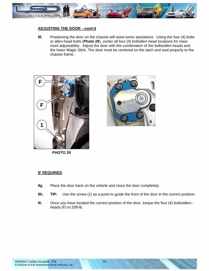
ADJUSTING THE DOOR –cont’d 9f. Positioning the door on the chassis will need some assistance. Using the four (4) bolts or allen-head bolts (Photo 29), center all four (4) bolt/allen-head locations for maxi- mum adjustability. Adjust the door with the combination of the bolts/allen-heads and the lower Magic Stick. The door must be centered on the latch and seal properly to the chassis frame.
PHOTO 29
IF REQUIRED 9g. Place the door back on the vehicle and close the door completely. 9h. TIP: Use the screw (1) as a point to guide the front of the door in the correct position. 9i. Once you have located the correct position of the door, torque the four (4) bolts/allen– heads (F) to 20ft-lb.
F
F
1
50063001 Cadillac Escalade 5/06 34 A Division of KW automotive North America, Inc
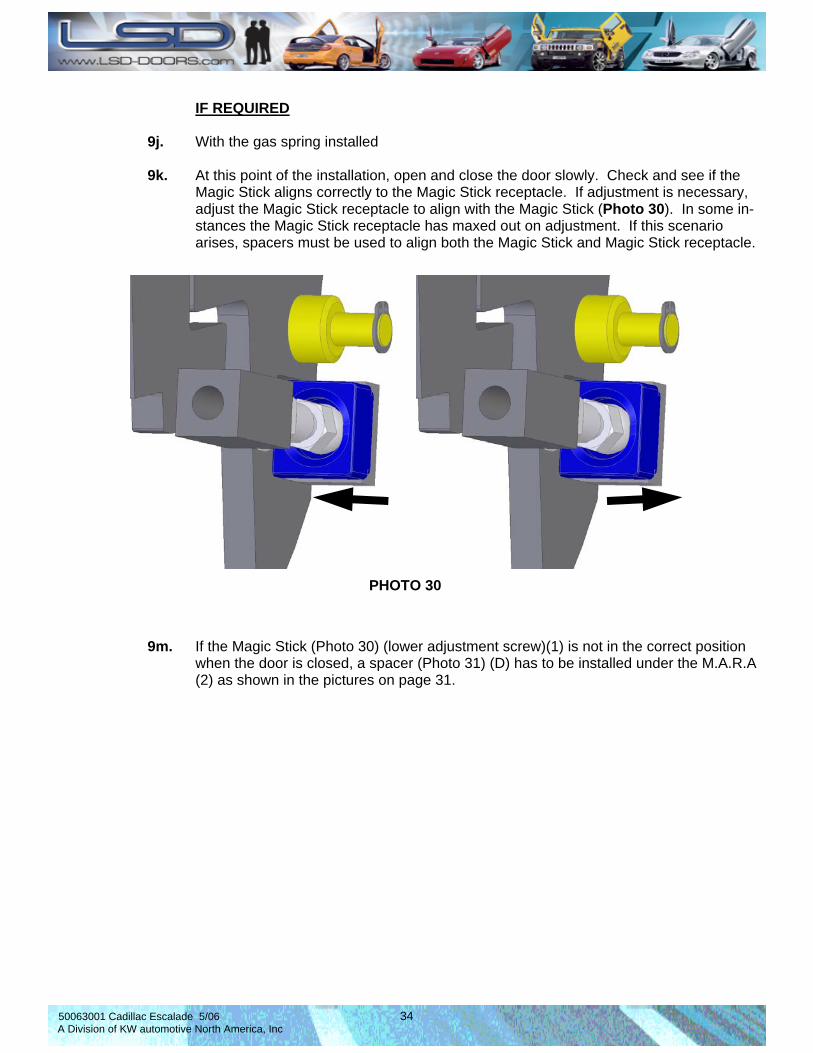
IF REQUIRED 9j. With the gas spring installed 9k. At this point of the installation, open and close the door slowly. Check and see if the Magic Stick aligns correctly to the Magic Stick receptacle. If adjustment is necessary, adjust the Magic Stick receptacle to align with the Magic Stick (Photo 30). In some in- stances the Magic Stick receptacle has maxed out on adjustment. If this scenario arises, spacers must be used to align both the Magic Stick and Magic Stick receptacle. 9m. If the Magic Stick (Photo 30) (lower adjustment screw)(1) is not in the correct position when the door is closed, a spacer (Photo 31) (D) has to be installed under the M.A.R.A (2) as shown in the pictures on page 31.
PHOTO 30

50063001 Cadillac Escalade 5/06 35 A Division of KW automotive North America, Inc
PHOTO 31
IF REQUIRED 9n. With the gas spring installed. 9p. If spacer (s) installation is needed, install one at a time, starting at the top, (Photo 31) working your way to the bottom, to see if that particular spacer aligns the door correctly. Begin at the top mounts, STEP 1A to STEP 1B, etc, etc.
D
D D
D
2
2
2
2
STEP 1A - TOP
STEP 1B - TOP
STEP 2A - BOTTOM
STEP 2B - BOTTOM
50063001 Cadillac Escalade 5/06 36 A Division of KW automotive North America, Inc
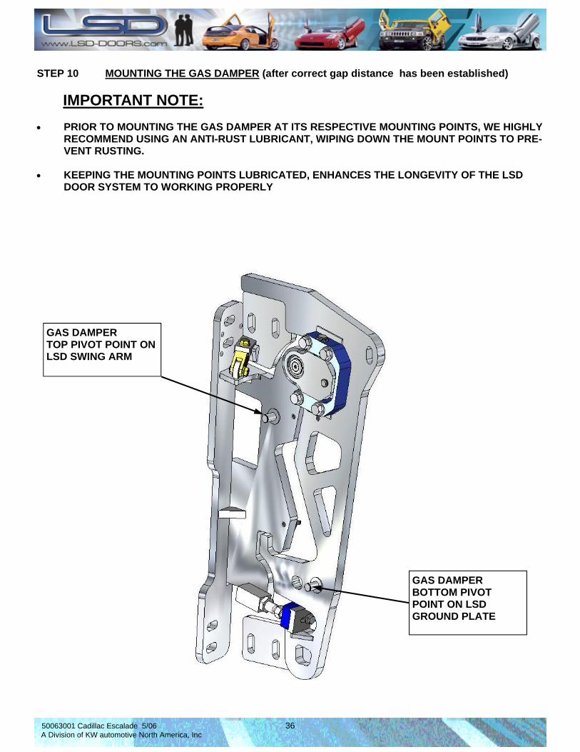
STEP 10 MOUNTING THE GAS DAMPER (after correct gap distance has been established) IMPORTANT NOTE: • PRIOR TO MOUNTING THE GAS DAMPER AT ITS RESPECTIVE MOUNTING POINTS, WE HIGHLY
RECOMMEND USING AN ANTI-RUST LUBRICANT, WIPING DOWN THE MOUNT POINTS TO PRE-VENT RUSTING.
• KEEPING THE MOUNTING POINTS LUBRICATED, ENHANCES THE LONGEVITY OF THE LSD
DOOR SYSTEM TO WORKING PROPERLY
GAS DAMPER TOP PIVOT POINT ON LSD SWING ARM
GAS DAMPER BOTTOM PIVOT POINT ON LSD GROUND PLATE
50063001 Cadillac Escalade 5/06 37 A Division of KW automotive North America, Inc
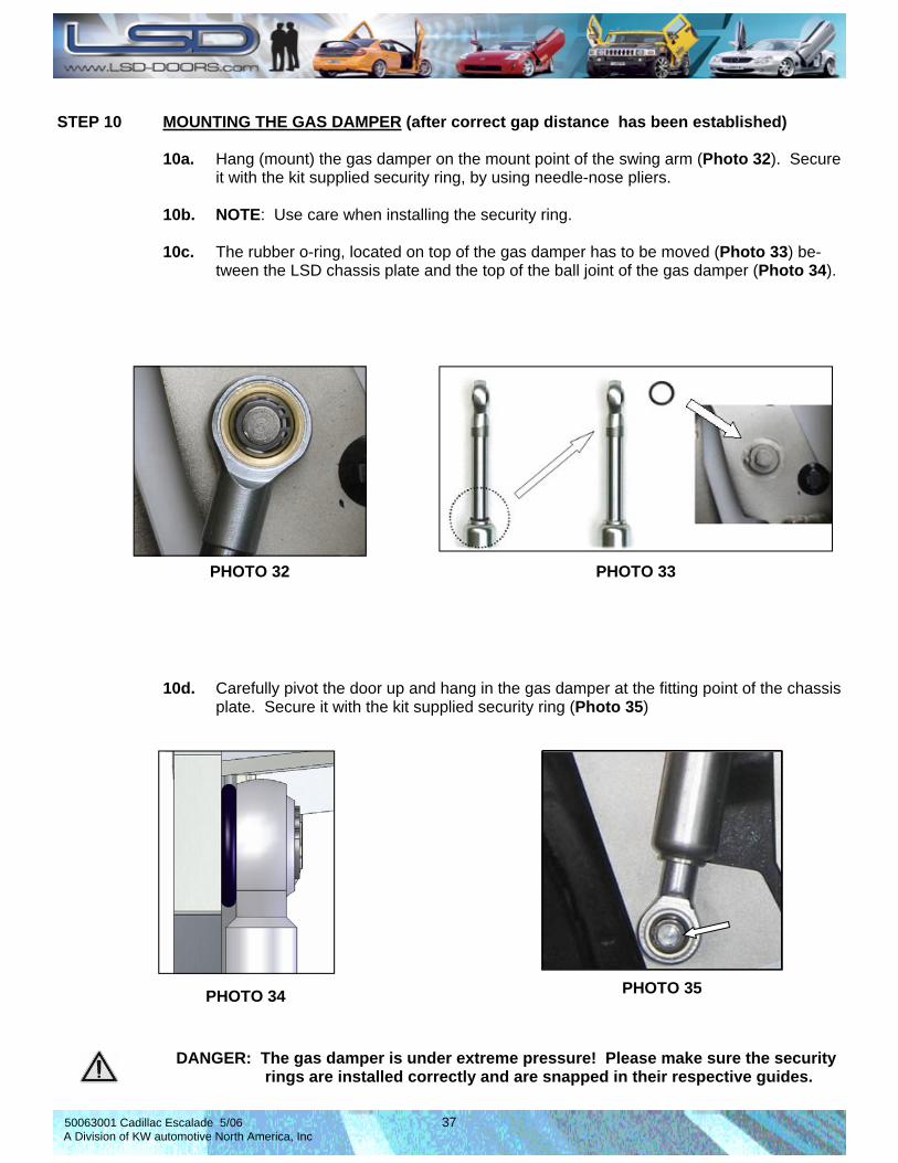
STEP 10 MOUNTING THE GAS DAMPER (after correct gap distance has been established) 10a. Hang (mount) the gas damper on the mount point of the swing arm (Photo 32). Secure it with the kit supplied security ring, by using needle-nose pliers. 10b. NOTE: Use care when installing the security ring. 10c. The rubber o-ring, located on top of the gas damper has to be moved (Photo 33) be- tween the LSD chassis plate and the top of the ball joint of the gas damper (Photo 34).
PHOTO 32 PHOTO 33
PHOTO 34
10d. Carefully pivot the door up and hang in the gas damper at the fitting point of the chassis plate. Secure it with the kit supplied security ring (Photo 35)
DANGER: The gas damper is under extreme pressure! Please make sure the security rings are installed correctly and are snapped in their respective guides.
PHOTO 35

50063001 Cadillac Escalade 5/06 38 A Division of KW automotive North America, Inc
10. MOUNTING THE SPACER (with gas spring installed) The spacer gives the newly installed LSD system rigidity, as it is attached directly to the frame of the vehicle (Photo 36). The following instructions on the following page shows how to lo- cate the spacer. Tools needed for this are listed. IMPORTANT NOTE: Also commonly known as the third point adjustment, this controls how the door opens. (See page 36), “COMMON QUESTIONS AND ANSWERS”, question 2. By using this adjustment, you can control if the door opens smoothly or abruptly.
PHOTO 36
DETAIL—AA 1 2 3
1/16
INC
H
11m
m(.4
3”)
Shown in DETAIL-AA above, are the sizes of drill bits needed to create the mounting holes:
HOLE PUNCH DRILL BIT (PILOT HOLE)(1/16” inch) DRILL BIT 11mm(.43”) INSERT (H)
1
2
3
E
G
H
4

50063001 Cadillac Escalade 5/06 39 A Division of KW automotive North America, Inc
11. MOUNTING THE SPACER –cont’d- (with gas spring installed) 11a. Closing the door again, let the door lock and set in place. 11b. Re-install the modified fender back on the vehicle to see if there are any obstructions. 11c. Remove the fender again and close the door. 11d. After you have made the final adjustments, insert a hole punch (for this example we are using a long bolt) through the mount hole on the plate (3) (Photo37a). 11e. Remove the ground plate. (Removal is optional. ) The use of a long drill bit can be used, locating the drill bit through the adjustment slot to the A-Pillar. 11f. Drill and tap a M11 at the point on the chassis where you have transferred the hole from (Photo 37b). Use this as a guide. 11g. Push the insert (H) into the newly drilled hole. 11h. Measure the distance between the backside of the ground plate to the frame (Photo 37c). Cut the kit supplied spacers and angle cut the new spacer according to the angle needed. 11i. Insert the bolt (I), flat washer (G), and the spacer (E) (Photo 37d). 11j. Tighten and torque the mounting hardware to 20ft-lb.
PHOTO 37a
3
PHOTO 37b
PHOTO 37c
E G
H
PHOTO 37d
LENGTH OF SPACER

50063001 Cadillac Escalade 5/06 40 A Division of KW automotive North America, Inc
STEP 12 ROUTING THE WIRE HARNESS 12a. Pivot the door carefully up and make sure there is sufficient clearance on the fender, A- pillar and hood. If necessary, adjust the LSD chassis plate or the LSD swing arm again. 12b. Lay the wire harness on and attach it to the marked points shown (Photo 38). Secure the wire harness with the kit supplied cable ties.
PHOTO 38
Allow for movement in this area, check with fender and door
Exact locations may vary for the amount of wiring on vehicle
Begins being located at the rear of the ground plate Dotted lines represent rear location
Route through lower door stop access hole.
50063001 Cadillac Escalade 5/06 41 A Division of KW automotive North America, Inc
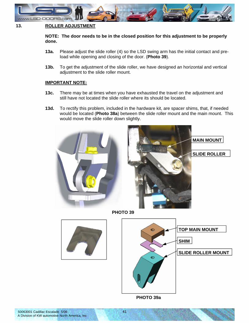
13. ROLLER ADJUSTMENT NOTE: The door needs to be in the closed position for this adjustment to be properly done. 13a. Please adjust the slide roller (4) so the LSD swing arm has the initial contact and pre- load while opening and closing of the door. (Photo 39). 13b. To get the adjustment of the slide roller, we have designed an horizontal and vertical adjustment to the slide roller mount. IMPORTANT NOTE: 13c. There may be at times when you have exhausted the travel on the adjustment and still have not located the slide roller where its should be located. 13d. To rectify this problem, included in the hardware kit, are spacer shims, that, if needed would be located (Photo 38a) between the slide roller mount and the main mount. This would move the slide roller down slightly.
PHOTO 39
MAIN MOUNT
SLIDE ROLLER
TOP MAIN MOUNT
SHIM
SLIDE ROLLER MOUNT
PHOTO 39a
50063001 Cadillac Escalade 5/06 42 A Division of KW automotive North America, Inc
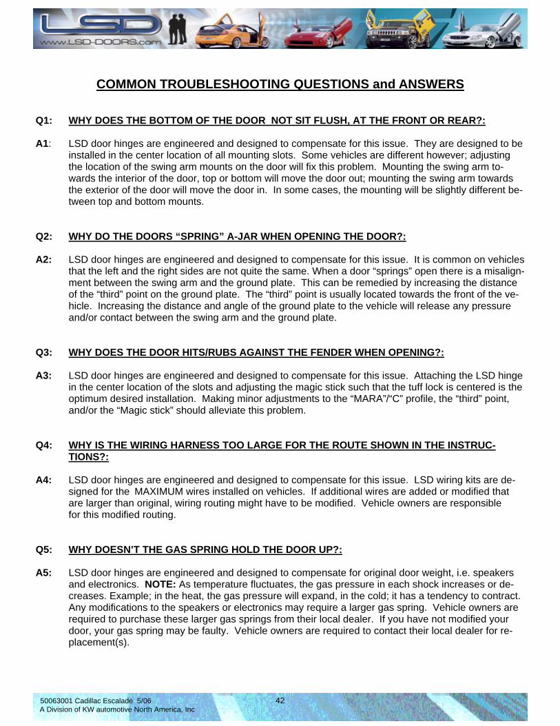
COMMON TROUBLESHOOTING QUESTIONS and ANSWERS
Q1: WHY DOES THE BOTTOM OF THE DOOR NOT SIT FLUSH, AT THE FRONT OR REAR?: A1: LSD door hinges are engineered and designed to compensate for this issue. They are designed to be installed in the center location of all mounting slots. Some vehicles are different however; adjusting the location of the swing arm mounts on the door will fix this problem. Mounting the swing arm to- wards the interior of the door, top or bottom will move the door out; mounting the swing arm towards the exterior of the door will move the door in. In some cases, the mounting will be slightly different be- tween top and bottom mounts. Q2: WHY DO THE DOORS “SPRING” A-JAR WHEN OPENING THE DOOR?: A2: LSD door hinges are engineered and designed to compensate for this issue. It is common on vehicles that the left and the right sides are not quite the same. When a door “springs” open there is a misalign- ment between the swing arm and the ground plate. This can be remedied by increasing the distance of the “third” point on the ground plate. The “third” point is usually located towards the front of the ve- hicle. Increasing the distance and angle of the ground plate to the vehicle will release any pressure and/or contact between the swing arm and the ground plate. Q3: WHY DOES THE DOOR HITS/RUBS AGAINST THE FENDER WHEN OPENING?: A3: LSD door hinges are engineered and designed to compensate for this issue. Attaching the LSD hinge in the center location of the slots and adjusting the magic stick such that the tuff lock is centered is the optimum desired installation. Making minor adjustments to the “MARA”/“C” profile, the “third” point, and/or the “Magic stick” should alleviate this problem. Q4: WHY IS THE WIRING HARNESS TOO LARGE FOR THE ROUTE SHOWN IN THE INSTRUC- TIONS?: A4: LSD door hinges are engineered and designed to compensate for this issue. LSD wiring kits are de- signed for the MAXIMUM wires installed on vehicles. If additional wires are added or modified that are larger than original, wiring routing might have to be modified. Vehicle owners are responsible for this modified routing. Q5: WHY DOESN’T THE GAS SPRING HOLD THE DOOR UP?: A5: LSD door hinges are engineered and designed to compensate for original door weight, i.e. speakers and electronics. NOTE: As temperature fluctuates, the gas pressure in each shock increases or de- creases. Example; in the heat, the gas pressure will expand, in the cold; it has a tendency to contract. Any modifications to the speakers or electronics may require a larger gas spring. Vehicle owners are required to purchase these larger gas springs from their local dealer. If you have not modified your door, your gas spring may be faulty. Vehicle owners are required to contact their local dealer for re- placement(s).
50063001 Cadillac Escalade 5/06 43 A Division of KW automotive North America, Inc
50063001 Cadillac Escalade 5/06 44 A Division of KW automotive North America, Inc

50063001 Cadillac Escalade 5/06 45 A Division of KW automotive North America, Inc

50063001 Cadillac Escalade 5/06 46 A Division of KW automotive North America, Inc