CAD/CAM Anterior and Posterior Implant Restorations ... · of in-office CAD/CAM techniques will be...
21
CAD/CAM Anterior and Posterior Implant Restorations: Ceramics, Abutments and Design Fabrication and design of implant abutments has been previously published. REF1,2 Using Cad/Cam software to design the final abutments has also increased precision of designs and decrease in laboratory fabrication times. REF3-7 The specific design programs require information from the clinician to better understand each specific tooth emergence for each site. Using radiographs, tissue bio-types and algorithmic equations, the design technician together with the clinician can better design the final contours and emergence that is necessary for ideal tissue support and long term tissue stability. The use of intra-oral digital acquisition units (Table 1) can also help the fabrication of Cad/Cam restorations that follow the emergence from the abutment to the final restoration. REF8,9 Using a coded healing abutment such as Encode® (Biomet 3I, Palm Beach Gardens, FL.) can further facilitate the transfer of digital information from the clinical environment to the laboratory, in a matter of minutes. In addition, the digital scan of the occlusal relationships are more precise and accurate than any stone casts. REF10 The use of in-office CAD/CAM techniques will be highlighted to fabricate implant posterior and anterior implant crowns. The new monolithic and feldspathic ceramic blocks can be utilized to fabricate life-like color and translucency as well as fit and marginal integrity REF11,12. Computerized and Cad/Cam prosthodontic care of our patients can be more efficient, more predictable and save chair time for our patients. KEY WORDS: coded abutments, digital acquisition, emergence with algorithmic equation, Cad/Cam restorations and abutments. TABLE 1 Various Digital Acquisition Softwares Digital Impression Digital Impression + In Office Milling Cad/Cam Abutments Lava / 3M ESPE iTero / Cadent E4D/ D4D Technologies Cerec AC 4.0/ Sirona Encode / Biomet 3 I Procera / Nobel Biocare Atlantis / Astra Tech Etkon System / Straumann CASE REPORT # 1 Four Single Unit Posterior Restorations Materials Used Coded Abutments (Bellatek™ Encode, Biomet 3I, Palm Beach Gardens)
Transcript of CAD/CAM Anterior and Posterior Implant Restorations ... · of in-office CAD/CAM techniques will be...
CAD/CAM Anterior and Posterior Implant Restorations: Ceramics, Abutments and Design
Fabrication and design of implant abutments has been previously published. REF1,2 Using Cad/Cam
software to design the final abutments has also increased precision of designs and decrease in
laboratory fabrication times. REF3-7 The specific design programs require information from the clinician
to better understand each specific tooth emergence for each site. Using radiographs, tissue bio-types
and algorithmic equations, the design technician together with the clinician can better design the final
contours and emergence that is necessary for ideal tissue support and long term tissue stability. The use
of intra-oral digital acquisition units (Table 1) can also help the fabrication of Cad/Cam restorations that
follow the emergence from the abutment to the final restoration. REF8,9 Using a coded healing abutment
such as Encode® (Biomet 3I, Palm Beach Gardens, FL.) can further facilitate the transfer of digital
information from the clinical environment to the laboratory, in a matter of minutes. In addition, the digital
scan of the occlusal relationships are more precise and accurate than any stone casts. REF10 The use
of in-office CAD/CAM techniques will be highlighted to fabricate implant posterior and anterior implant
crowns. The new monolithic and feldspathic ceramic blocks can be utilized to fabricate life-like color and
translucency as well as fit and marginal integrity REF11,12. Computerized and Cad/Cam prosthodontic
care of our patients can be more efficient, more predictable and save chair time for our patients.
KEY WORDS: coded abutments, digital acquisition, emergence with algorithmic equation, Cad/Cam
restorations and abutments.
TABLE 1 Various Digital Acquisition Softwares
Digital Impression Digital Impression +
In Office Milling
Cad/Cam Abutments
Lava / 3M ESPE
iTero / Cadent
E4D/ D4D Technologies
Cerec AC 4.0/ Sirona
Encode / Biomet 3 I
Procera / Nobel Biocare
Atlantis / Astra Tech
Etkon System / Straumann
CASE REPORT # 1 Four Single Unit Posterior Restorations
Materials Used
Coded Abutments (Bellatek™ Encode, Biomet 3I, Palm Beach Gardens)

Final Impression with Elastomeric material (Impregum-F, ESPE)
Stone Casts (Fuji-rock, GC)
Cad/Cam Abutment Design (3-Shape Abutment Designer™/Bellatek, Biomet 3i )
Final Abutments ; Titanium, nitrite coated internal connection( NanoTite Certain)
Cad/Cam Acquisition Units (Cerec 3D, Sirona Systems)
Laboratory, NY Smile Labs, New York, NY
Restorative Material: Monolithic Lithium Disilicate (E-max Cad Block LT, Ivoclar/Vivadent)
Cement Utilized = Temrex, Temrex Corp. (provisional) and RelyX, 3MEspe (permanent)
Restoration Term = 38 months
Procedures
Patient presented with missing posterior teeth and posterior restorations exhibited occlusal wear
and fractured porcelain. FIGURE 1 The patient was treatment planned for sinus augmentation
surgery (lateral window technique, Bioss Osteohealth Co.with bio-guide membrane )t o increase
bone size and width. Six months after surgery patient was treated with single stage placement of
two endosseous implants (Certain Osseotite NT, Biomet 3i , Palm Beach Gardens, Fl).FIGURE 2
In addition, computer coded healing abutments (Encode, Biomet 3i ) were placed at stage I for the
duration of the osseointegration process. The patient had a ceramo-metal provisional fixed partial
denture placed (PFM long-term provisional) with single unit cantilever extensions bi-laterally.
FIGURE 3
After 6 months of healing the patient presented to the prosthodontic office to complete the implant
restorations. A final impression with elastomeric material of the coded healing abutments was made. An
impression of the opposing teeth and an occlusal registration in MIP was made on the first restorative
visit. The coded healing abutments were never removed, nor was a fixture level impression necessary
with this technique. The maxillary and mandibular impressions were poured and the casts were delivered
to the laboratory for mounting. The casts mounted on a specific articulator (Stratos) and delivered to the
digital facility for digital scanning. Once the scanning was complete, the design of the final abutments
begins.
FIGURE 4,5
Design of Final Abutments
There are three areas of clinical importance for designing the abutment and their relative importance is
as follows:

1- Gingival Margin Position, relates to = Bio-type of Tissue
2- Depth of Tissue around Abutment, relates to = Radiograph of Bone
3- Angle of the Emergence, relates to = Algorithmic Equation to determine Tissue Displacement.
GINGIVAL MARGIN
The first is the level of the gingival margin of the abutment. This is specifically requested by the
clinician and relates to the bio-type of the tissue around the restorable area. In this patient treatment
the margin was set to 0.5 mm below the free gingival margin that was thick keratinized bio-type.
Figure 6
DEPTH of TISSUE
The second critical design characteristic is the depth of the tissue around the abutment. This can be
measured by probing depth to the implant fixture head, or digitally by the digital software design team.
Using the radiograph of the healing coded abutment can give the design team information that can
better determine the gingival width allowed by the anatomy of each specific tooth site. FIGURE 7
EMERGENCE ANGLE and CONTOUR
The angle of emergence profile it creates from each specific tooth, as it goes through the tissue. This
can be designed to be straight, concave or convex. The angle of emergence can be calculated by the
algorithm formula and table ( X, Y and Z axes) shown below. This characteristic is essential in the
final emergence profile. In addition, the occlusal clearance to the opposing dentition must have
adequate clearance for ceramic restorative material and for support is necessary. In this patient
treatment the occlusal clearance was set to 2.0mm. FIGURE 8
FINAL MARGIN WIDTH
The width of the gingival floor of the abutment will also be determined at this step.
The minimum thickness for this technique and the correct use of the future restoration is 1.2mm. For
larger restorations the width of the gingival margin can be up to 1.7mm. In this patient treatment the
width was assigned at 1.5mm. The larger the width of the gingival floor the more support it will give
the ceramic restoration. In addition, the shoulder design is used instead of the chamfer design
because the margin gap distance has been shown to be reduced with this design REF13. This is why
using pre-fabricated abutments may be contraindicated with CAD/CAM ceramic crowns. Figure 9

At a different section of the scanning facility, the placement of the analog is performed by a robotic arm
that has received the data points from the scanned model. This designates the exact position in the
mathematical X, Y and Z axes, and translates this to the robotic arm. The depth of placement, the hex
position and the angle of the analog are simultaneously inserted into the computer program. The model
is drilled and the analog is placed in position on the final working cast. Once the design is approved by
the clinician or laboratory, the final abutment is milled from either a titanium material or zirconia material.
The abutments are polished and finished and returned with the casts to the to the laboratory. The
laboratory delivers the final abutments on the working model to the restorative clinician.
Digital Scanning of the Abutments at the Office
Using a cad/cam intra-oral scanner (Cerec 3D blue/cam, Sirona), the casts are prepared for scanning.
Light powder is applied to the abutments, and the access hole is temporarily sealed with cotton ball and
flowable light cured composite resin. FIGURE 10 In the preparation window of the design software the
digital scans are captured of the abutment. The amount of digital picture scans depends on the size of
the restoration and how many adjacent teeth are involved. The average is 7-8 scans. In the occlusal
window of the design software a digital scan of the inter-maxillary record (Regisil, Dentsply) is captured.
FIGURE 11 Once the digital images have been approved the abutment margins are highlighted and
verified for exact position. This is called margination. This the exact margin that the restoration will be
milled to. In the settings mode, the parameters for each type of restoration can be adjusted for each
clinicians preference. Some of these parameters include, occlusal offset, margin thickness, cement
spacer, and restoration thickness. Using the data base mode of the scanner, a restoration is designed for
each specific abutment. Figure 12
Each restoration must be designed separately and then merged together on the final master digital
mode. Additional design features such as addition and smooth tool can be used to finalized the shape
each restoration. How many occlusion contacts and where they should be positioned is critical in implant
occlusion design. Inter-proximal contacts are also adjusted to desired position. Figure 13
After the final design is approved, it is sent to the milling center for final mill. The designated blocks
chosen for this patient treatment were E-max Cad blocks LT ( Ivoclar/Vivadent, Amherst, NY).
In the pre-glazed phase( purple) after milling they are tried intra-orally for final occlusion and contact
point correction in their, pre-glazed phase.Figure 14 After approval of fit and position they are placed in
the firing oven for final crystallization and glaze. Final readiographs are taken and then they are
cemented with provisional cement for 4 weeks (Temrex, Inc.) Final cement used was a dual cured resin
cement( Rely-X 3M ESPE, St Paul, MN). Final occlusion was confirmed with digital occlusion analysis.
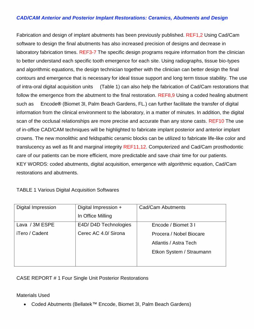
(Tekscan, Boston, Mass.) Patient was returned for follow-up in 3 and 6 weeks respectively. Figure 15,
16, 17, 18

FIGURE 1
figure 2
Figure 3
figure 4

figure 5
Figure 6
figure 7
Figure 8

figure 9
figure 10
figure 11
figure 12

Figure 13
Figure 14
Figure 15

Figure 16
figure 17
figure 18

CASE 2 Anterior Central Incisor # 9
Materials Used
Coded Abutments (Bellatek™ Encode, Biomet 3I, Palm Beach Gardens)
Final Impression with Intra-oral Digital Acquisition ; LAVA COS ( 3M Espe)
SLR Models Created
Cad/Cam Abutment Design (3-Shape Abutment Designer/Bellatek, Biomet 3i)
Final Abutment; Zirconia, internal connection (Certain, Biomet 3i)
Final Impression of abutment with E4D, D4D Technologies
Restorative Material: Luecite Reinforced Ceramic Cad Block (Empress CAD HT, Ivoclar)
Laboratory: NY Smile Labs, New York, NY
Cement Utilized = RelyX, 3M (permanent)
Restoration Term = 3 months
Patient presented with missing upper left central incisor. Figures 1,2 A 4.0mm wide endosseos implant
was placed (NanoTite, Certain, Biomet 3i). A coded healing abutment (Encode, BIOMET 3i) was placed
3 months after stage I to heal the gingival tissue. Figure 3. A fixed bonded provisional (Emax pressed
ceramic) was placed for the 4 month period of healing. FIGURE 4. The provisional was removed after 6
weeks and a digital impression of the coded healing abutment was made with an intra-oral scanner.(Lava
COS, 3M Espe). Digital scan of the opposing arch and lateral view of the inter-occlusal relationship in
MIP was made. All three scans were combined by the Lava software, and the clinical evaluation was
analyzed by the clinician for accuracy of the captured scans. The files were emailed to the digital facility
(Architect PSR, Biomet 3i) and were then transferred to 3-D shape software for design. Figures 5,6,7
The final abutment was designed based on bio-type, radiograph and angulation of emergence. This will
determine the margin placement, the emergence type and the angle of emergence through the tissue.
The final design was emailed to the clinician for approval. Figure 8, 9,10 Algorithm for displacement of
tissue was applied for final contour and emergence profile. Figure 11After minor change in the margin
placement the abutment was ready for milling. The choice was made to use zirconia material for better
color through the tissue in the aesthetic zone. After milling, the final abutment was sent to clinician. It was

then screwed in place and radiographed for proper position. Figure12,13,14. A provisional restoration
was made and cemented for 3 weeks for additional tissue maturation. Figure 15.The patient returned for
final restoration and the abutment was ready to be scanned. An intra-oral scanner is used to scan the
final preparation and margin in the final position (E4D system, D4D Technologies, Richardson, TX).
Several scans are required to create a virtual model. The opposing arch and a bite registration is also
scanned to create all the information necessary to design the final restoration. Using several design tools
and “autogenesis” biologic contours of central incisor, the proper contour and anatomy for this restoration
is created. Final adjustments are made by the clinician and the occlusal contacts are confirmed. Figure
16, 17, 18, The material of choice in this restoration was designated as Empress-Cad HT block, Vita
shade A2 (Ivoclar,Vivadent).The file is sent to the milling center. The final milling is completed and the
restoration is tried in the mouth for accuracy and marginal integrity. Figure 19 Radiograph of the
restoration is taken to verify fit. Final contour and shape is verified intra-orally. Light reflection and heights
of contours are viewed with water and overhead light. Final stain and glaze is placed intra-orally to match
adjacent tooth, color and texture. The restoration is placed in the oven and glazed at manufacturers
suggested firing times. ( High Temp 790 °C). FIGURE 20 The abutment is cleaned and prepared for final
restoration with micro-etching (50particle size). The restoration is etched and cemented definitively with
dual cure resin cement( Rely-X, 3MEspe). The patient returned after 4 weeks for follow up visit and
occlusal analysis.

Figure 1
Figure 2

Figure 3
Figure 4
Figure 5
Figure 6

Figure 7
Figure 8
Figure 9

Figure 10
Figure 11

Figure 12
Figure 13
Figure 14
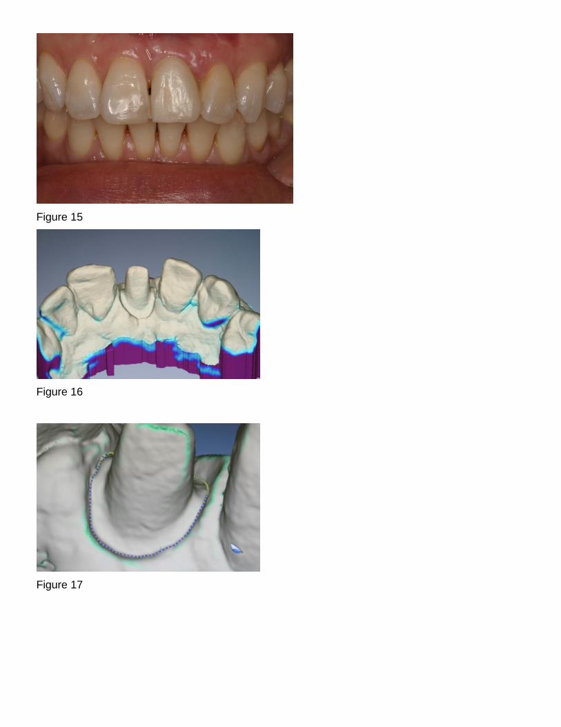
Figure 15
Figure 16
Figure 17

Figure 18
Figure 19
Figure 20

ADVANTAGES
Avoiding conventional steps such as impression material, gag reflex, pouring, mounting, alginate,
bagging, delivery, pindex, ditching, etc.
Reduces laboratory costs and lab time
Saves time for clinician, laboratory and patient
Most accurate inter-occlusal records to date
Margin capture and review more easily seen than cast ditching
Less re-makes
Saves office costs due to materials, trays, dental assistant.
Impressive technology for patients
Promotes better preparations
Digital Files can be transferred with back up and no loss of cases
Digitally trained designers
DISADVANTAGES
Cost of scanners
Learning curve 2-3 months
Complete isolation, which means no tissues and no fluids in the scanning field
Bulky equipment in the operatory
Continuing education


REFERENCES
1- Binon, PP. Evaluation of machining accuracy and consistency of selected implants, standard
abutments and laboratory analogs. Int. J. Prosthodont. 1995; 8(2):162-178
2- Finger, IM. Castellon, P. Block, M. Elian, N. The evolution of external and internal
implant/abutment connections. PPAD 203;15(8):625-632
3- Priest,G. Virtual designed and computer milled implant abutments. J Oral Maxillofac Surg.
2005;63:22-32
4- Grossman,Y. Pasciuta, M. Finger,I.M. A novel technique using a coded healing abutment for the
fabrication of a Cad/Cam titanium abutment for an implant supported restoration. J Prosthet Dent
2006;95:258-61
5- Drago, CJ. Two new clinical/laboratory protocols for CAD/CAM implant restorations. J Am Dent
Assoc. 2006;137:794-800
6- Vafiadis, DC. Computer generated abutments using a coded healing abutment: A two year
preliminary report. PPAD 2007;19(7):443-448
7- Vafiadis, DC. Full arch restorations using computerized abutments. Implant Dent. Today, June
2011; 30-35
8- Birnbaum, NS. Aaronson, HB. Digital Impressions Using 3D Digital Scanners. Compedium 2008;
Vol 29:Issue 8
9- Patel, N. Integrating three-dimensional digital technologies for comprehensive implant
dentistry. JADA 2010 Vol 141(6 Suppl); 20S-24S
10- Christensen, GJ. Will digital impressions eliminate the current problems with
conventional impressions. JADA June 2008;139(6)761-763
11- Guess, P.C. , Zavanelli, R.A., Nelson R., Silva, F.A., Bonfante, E.A., Coelho, P.G.,
Thompson, V.P. Monolithic CAD/CAM Lithium Disilicate Versus Veneered Y-TZP
Crowns: Comparison of Failure Modes and Reliability After Fatigue Int J Prosthodont
2010;23:434–442.
12- Vafiadis, DC. Goldstein,G. Single visit fabrication of a porcelain laminate veneer with Cad/Cam
technology: a clinical report. J Prosthet Dent 2011;106:71-73
13- Akbar, JH. Petrie,CS. et.a. Marginal adaptation of Cerec 3 Cad/Cam crowns using two different
line preparation designs. J Prosthodontics 2006; 15:155-163