CAD TRANSLATION TRAPS USING DIFFERENT INTEGRATED …
9
CAD TRANSLATION TRAPS USING DIFFERENT INTEGRATED DESIGN SYSTEM IN VIRTUAL ENTERPRISE ENVIRONMENT UTILIZING STEP STANDARD AND SADT TECHNIQUE Carmen Cristiana, BUCUR University Politehnica of Bucharest, PREMINV - Virtual Enterprises Management and Engineering Research Laboratory, [email protected] Keywords : CAD, virtual enterprise, data translation, STEP, SADT Abstract The main focus of this paper is to sketch the SADT frame of an IDS data transfer model in order to improve CAD/CAM communication. Of course this isn’t the final goal of my research. In the future I intend to transpose SADT diagrams in a programming language and to elaborate a CAD/CAM interface. The case study presented in the previous chapter is not finished. The finally results will be published when ready. The study will consist in analyzing data translation (3D parts) between those CAD/CAM/CAE (Computer Aided Design/Computer Aided Manufacturing/Computer Aided Engineering) programming applications. 1. INTRODUCTION Modern CAD systems such as AutoCAD, CATIA V5, SOLID EDGE, Unigraphics, SOLID WORKS, Mechanical Desktop, 1-DEAS, Pro/Engineer are capable of creating models of objects in several different forms. They may be wireframe, surface, or solid. These models can be further processed to provide the geometry necessary for analysis by other programs. Thus, for example, stress or thermal analysis can be done prior to the production of actual hardware [1]. There are two-dimensional and three-dimensional CAD systems. In two- dimensional system the graphics screen is used as a substitute for drawing paper. All drawings are produced only in one plane without any depth. Most of the larger CAD systems have ability to model in three dimensions. The spatial image of the object is drawn in a pictorial projection using x-y-z co-ordinate geometry and is stored in the memory. It can be recalled and redrawn in 3-D pictorial projection or in orthographic projection representing the image of the object in a number of 2-D views, i.e. the front, end, plan and auxiliary views [2]. 2. CAD MODELING Geometrical modeling is a general term applied to three-dimensional computer- aided design techniques. There are three main types of geometrical modeling used, namely: line or wireframe modeling, surface modeling and solid modeling. Each has their own particular applications in the design of engineering components which is dependent on the ability of the method to model certain geometric structures effectively and generate the correct data for analysis. The usefulness of the model in the design process depends on whether it is a line, surface or solid model or in fact any combination of the three. Each method has its own capabilities in allowing the designer to visualize and analyze the model but all should interface to 2D drawing so that a working engineering drawing of a 3D model can be generated [3]. A wireframe representation is a 3-D line drawing of an object showing only the edges without any side surface in between. The image of the object, as the name applies has the appearance of a frame constructed from thin wires representing the edges and projected lines and curves if required, as shown in Figure 1(a). The main disadvantage of ANNALS of the ORADEA UNIVERSITY. Fascicle of Management and Technological Engineering, Volume VI (XVI), 2007 1247
Transcript of CAD TRANSLATION TRAPS USING DIFFERENT INTEGRATED …
CAD TRANSLATION TRAPS USING DIFFERENT INTEGRATED DESIGN SYSTEM IN VIRTUAL ENTERPRISE ENVIRONMENT UTILIZING STEP
STANDARD AND SADT TECHNIQUE
Carmen Cristiana, BUCUR University Politehnica of Bucharest, PREMINV - Virtual Enterprises Management and
Engineering Research Laboratory, [email protected] Keywords : CAD, virtual enterprise, data translation, STEP, SADT Abstract The main focus of this paper is to sketch the SADT frame of an IDS data transfer model in order to improve CAD/CAM communication. Of course this isn’t the final goal of my research. In the future I intend to transpose SADT diagrams in a programming language and to elaborate a CAD/CAM interface. The case study presented in the previous chapter is not finished. The finally results will be published when ready. The study will consist in analyzing data translation (3D parts) between those CAD/CAM/CAE (Computer Aided Design/Computer Aided Manufacturing/Computer Aided Engineering) programming applications. 1. INTRODUCTION Modern CAD systems such as AutoCAD, CATIA V5, SOLID EDGE, Unigraphics, SOLID WORKS, Mechanical Desktop, 1-DEAS, Pro/Engineer are capable of creating models of objects in several different forms. They may be wireframe, surface, or solid. These models can be further processed to provide the geometry necessary for analysis by other programs. Thus, for example, stress or thermal analysis can be done prior to the production of actual hardware [1].
There are two-dimensional and three-dimensional CAD systems. In two-dimensional system the graphics screen is used as a substitute for drawing paper. All drawings are produced only in one plane without any depth. Most of the larger CAD systems have ability to model in three dimensions. The spatial image of the object is drawn in a pictorial projection using x-y-z co-ordinate geometry and is stored in the memory. It can be recalled and redrawn in 3-D pictorial projection or in orthographic projection representing the image of the object in a number of 2-D views, i.e. the front, end, plan and auxiliary views [2].
2. CAD MODELING
Geometrical modeling is a general term applied to three-dimensional computer-
aided design techniques. There are three main types of geometrical modeling used, namely: line or wireframe modeling, surface modeling and solid modeling. Each has their own particular applications in the design of engineering components which is dependent on the ability of the method to model certain geometric structures effectively and generate the correct data for analysis. The usefulness of the model in the design process depends on whether it is a line, surface or solid model or in fact any combination of the three. Each method has its own capabilities in allowing the designer to visualize and analyze the model but all should interface to 2D drawing so that a working engineering drawing of a 3D model can be generated [3].
A wireframe representation is a 3-D line drawing of an object showing only the edges without any side surface in between. The image of the object, as the name applies has the appearance of a frame constructed from thin wires representing the edges and projected lines and curves if required, as shown in Figure 1(a). The main disadvantage of
ANNALS of the ORADEA UNIVERSITY.
Fascicle of Management and Technological Engineering, Volume VI (XVI), 2007
1247

this wire frame representation is that the hidden detail lines are shown and the resulting drawing is a maze of lines, which can be very confusing and disorientating. 3-D solid modeling. Some CAD systems are capable of producing the complete solid models of the objects in color, displaying full surfaces with the light, highlights and shadows, thus accomplishing very realistic images (Figure 1(b)). 2.5-D type of figures are wire frame representations, where the original 2-D shape can be translated or rotated into a 3-D shape as shown in Figure 1 (c).
Figure 1 (a) Wire frame, (b) Solid model and (c) 2.5-type model
Surface modeling is more sophisticated than wire frame representation, but is
cheaper to run than solid modeling. Initially the wire frame is created and the gaps between all individual frames are then filled in by flat or rounded surfaces. This model can be easily modified and color shaded, if required [4].
3. ABOUT STEP
ISO 10303 is known as STEP or the Standard for the Exchange of Product model
data. It is an International Standard for the computer-interpretable representation and exchange of industrial product data. The objective is to provide a mechanism that is capable of describing product data throughout the life cycle of a product, independent from any particular system. The nature of this description makes it suitable not only for neutral file exchange, but also as a basis for implementing and sharing product databases and archiving [5].
Typically STEP can be used to exchange data between CAD, CAM, CAE, PDM/EDM and other systems CAx. STEP is addressing product data from mechanical and electrical design, analysis and manufacturing, with additional information specific to various industries such as automotive, aerospace, building construction, ship, oil & gas, process plants and others.
STEP is divided into many parts, grouped into: Environment
− Parts 1x: Description methods: EXPRESS, EXPRESS-X − Parts 2x: Implementation methods: STEP-File, STEP-XML, SDAI − Parts 3x: Conformance testing methodology and framework
Integrated data models − Parts 4x and 5x: Integrated generic resources − Parts 1xx: Integrated application resources − Parts 5xx: Application integrated constructs (AIC) − Parts 1xxx: Application modules (AM)
Top parts − Parts 2xx: Application protocols (AP) − Parts 3xx: Abstract test suites (ATS) for APs − Parts 4xx: Implementation modules for APs
ANNALS of the ORADEA UNIVERSITY.
Fascicle of Management and Technological Engineering, Volume VI (XVI), 2007
1248
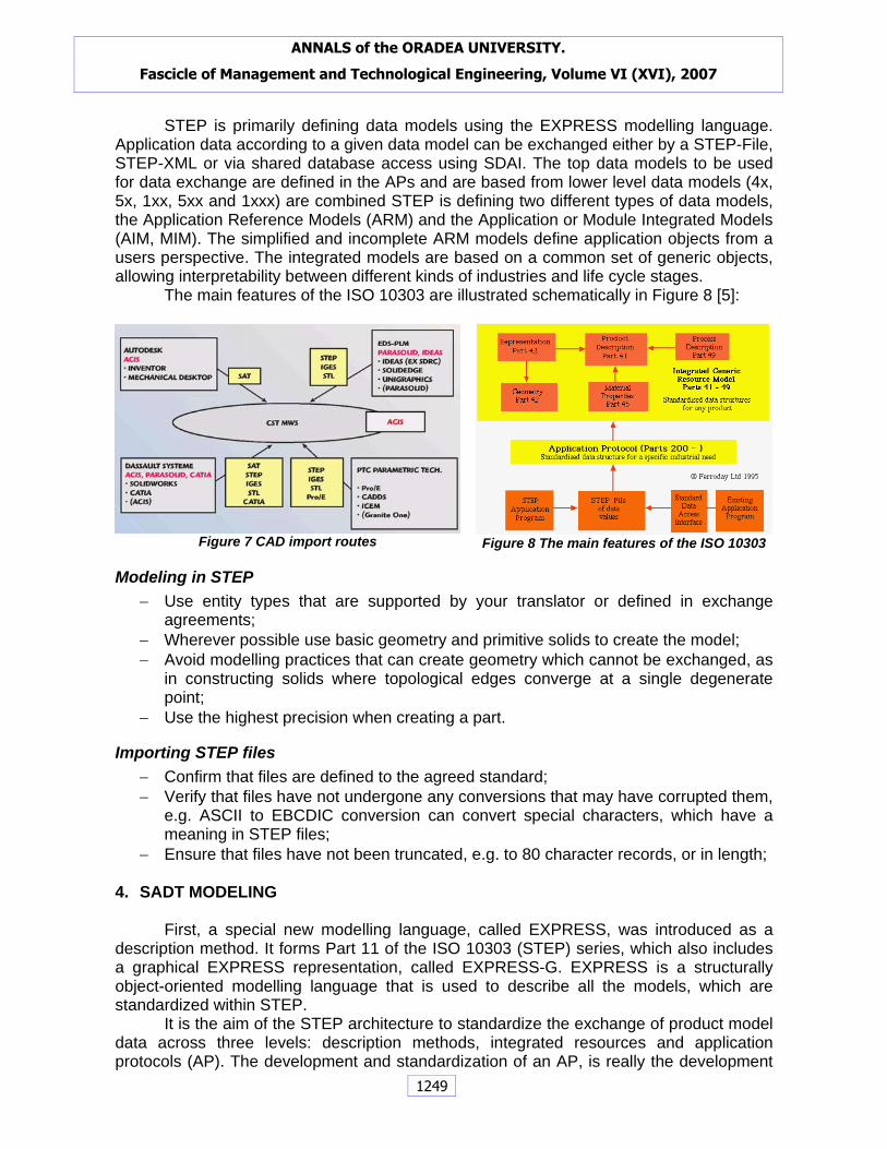
STEP is primarily defining data models using the EXPRESS modelling language. Application data according to a given data model can be exchanged either by a STEP-File, STEP-XML or via shared database access using SDAI. The top data models to be used for data exchange are defined in the APs and are based from lower level data models (4x, 5x, 1xx, 5xx and 1xxx) are combined STEP is defining two different types of data models, the Application Reference Models (ARM) and the Application or Module Integrated Models (AIM, MIM). The simplified and incomplete ARM models define application objects from a users perspective. The integrated models are based on a common set of generic objects, allowing interpretability between different kinds of industries and life cycle stages.
The main features of the ISO 10303 are illustrated schematically in Figure 8 [5]:
Figure 7 CAD import routes Figure 8 The main features of the ISO 10303
Modeling in STEP − Use entity types that are supported by your translator or defined in exchange
agreements; − Wherever possible use basic geometry and primitive solids to create the model; − Avoid modelling practices that can create geometry which cannot be exchanged, as
in constructing solids where topological edges converge at a single degenerate point;
− Use the highest precision when creating a part.
Importing STEP files − Confirm that files are defined to the agreed standard; − Verify that files have not undergone any conversions that may have corrupted them,
e.g. ASCII to EBCDIC conversion can convert special characters, which have a meaning in STEP files;
− Ensure that files have not been truncated, e.g. to 80 character records, or in length; 4. SADT MODELING
First, a special new modelling language, called EXPRESS, was introduced as a description method. It forms Part 11 of the ISO 10303 (STEP) series, which also includes a graphical EXPRESS representation, called EXPRESS-G. EXPRESS is a structurally object-oriented modelling language that is used to describe all the models, which are standardized within STEP.
It is the aim of the STEP architecture to standardize the exchange of product model data across three levels: description methods, integrated resources and application protocols (AP). The development and standardization of an AP, is really the development
ANNALS of the ORADEA UNIVERSITY.
Fascicle of Management and Technological Engineering, Volume VI (XVI), 2007
1249

of a standard for the exchange of product data in a given domain. To do this, several intermediate models are set up: the “application activity model” (AAM), which is not a data model, but is similar in concept to an SADT activity model, the “application reference model” (ARM) and finally the “application interpreted model” (AIM).
An example for APs is AP214 (“Core data for automotive mechanical design processes”). [5]
In the 1970’s, IDEF0 originated in the U.S. Air Force under the Integrated Computer Aided Manufacturing(ICAM) program from a well-established graphical language, the Structured Analysis and Design Technique (SADT).
SADT consists of procedures that allow the analyst to decompose software (or system) functions; a graphical notation, the SADT actigrammes and datagram (Figure 9), that communicate the relationships of information (data and control) and function within software, and project control guidelines for applying the methodology [6].
Inputs are data items that are transformed to outputs. Controls are items such as budget and schedule that constraint the type of degree of the process being described.
b)
Output activityInput activityDATA
Control activity
Mechanism Figure 9. The SADT basic diagrams: a) activity model, b) data model
The A-0 diagram is the highest level diagram in the SADT approach to process
mapping. It shows the overall context within one box. The A0 diagram is the first level diagram in the SADT process mapping methodology. It shows the first sub-processes.
Mechanisms are external aids to the process, such as tools and techniques used to perform the transformation. As with many other methods, the diagrams are arranged in a hierarchy to show more detail at lower levels [6].
Each diagram represents a transformation, and at most six diagrams are used to describe a function. If more than six diagrams are needed, the function should be redefined as a set of subfunctions. The diagram includes four factors: inputs, controls, mechanisms, and outputs.
The SADT methods has been exploited in order to structure the research oriented towards the realization of the directory scheme, for a better definition of the existing situation and for detaching the functional specifications of the projected system, which has to meet an analysis of the needs. We chose the actigrammes as tools of shaping in our analysis. We understand to call “actigram” those diagrams of the model, which are graphically represented as boxes designated by verbs, sometimes accompanied by complementation data are represented by arrows and designated by names. This representation allows a description of the series or parallel activities, as well as of feedbacks. The model is hierarchically constructed. At its most general interpretation, the system is perceived as a simple box. We can therefore expand and decompose this box, thus creating a first diagram, which can provide wider information in the field. The boxes of this diagram can be deconstructed in their turn, and can create new diagrams, and so on and so forth, until we reach the proper level of detail.
ANNALS of the ORADEA UNIVERSITY.
Fascicle of Management and Technological Engineering, Volume VI (XVI), 2007
1250
5. CASE STUDY
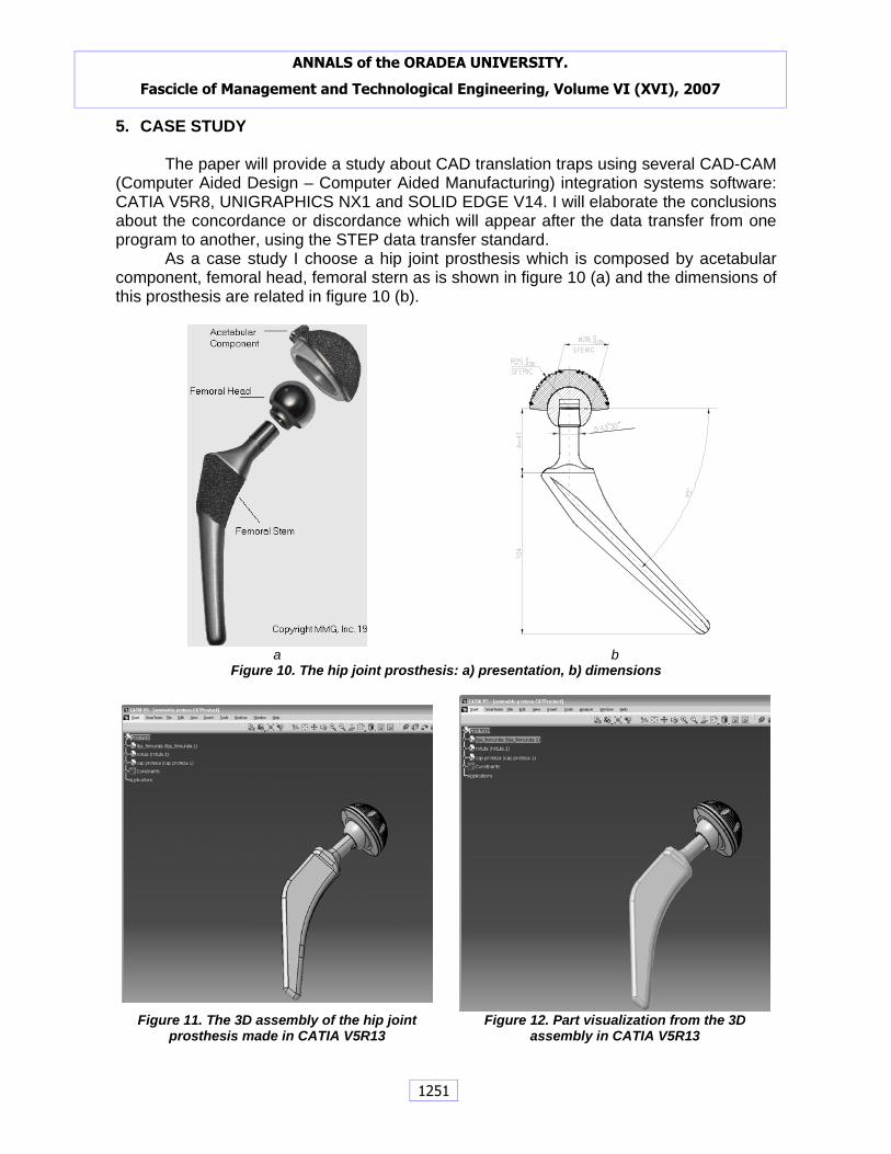
The paper will provide a study about CAD translation traps using several CAD-CAM (Computer Aided Design – Computer Aided Manufacturing) integration systems software: CATIA V5R8, UNIGRAPHICS NX1 and SOLID EDGE V14. I will elaborate the conclusions about the concordance or discordance which will appear after the data transfer from one program to another, using the STEP data transfer standard.
As a case study I choose a hip joint prosthesis which is composed by acetabular component, femoral head, femoral stern as is shown in figure 10 (a) and the dimensions of this prosthesis are related in figure 10 (b).
a b
Figure 10. The hip joint prosthesis: a) presentation, b) dimensions
Figure 11. The 3D assembly of the hip joint
prosthesis made in CATIA V5R13 Figure 12. Part visualization from the 3D
assembly in CATIA V5R13
ANNALS of the ORADEA UNIVERSITY.
Fascicle of Management and Technological Engineering, Volume VI (XVI), 2007
1251
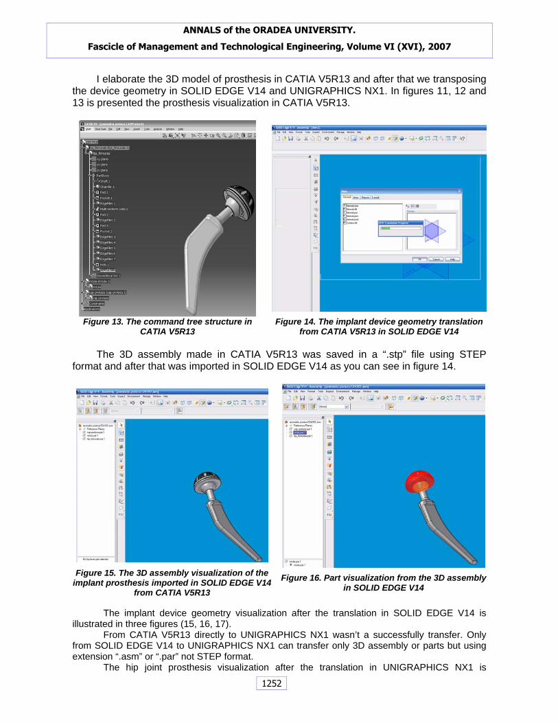
I elaborate the 3D model of prosthesis in CATIA V5R13 and after that we transposing the device geometry in SOLID EDGE V14 and UNIGRAPHICS NX1. In figures 11, 12 and 13 is presented the prosthesis visualization in CATIA V5R13.
Figure 13. The command tree structure in
CATIA V5R13 Figure 14. The implant device geometry translation
from CATIA V5R13 in SOLID EDGE V14
The 3D assembly made in CATIA V5R13 was saved in a “.stp” file using STEP format and after that was imported in SOLID EDGE V14 as you can see in figure 14.
Figure 15. The 3D assembly visualization of the
implant prosthesis imported in SOLID EDGE V14 from CATIA V5R13
Figure 16. Part visualization from the 3D assembly in SOLID EDGE V14
The implant device geometry visualization after the translation in SOLID EDGE V14 is
illustrated in three figures (15, 16, 17). From CATIA V5R13 directly to UNIGRAPHICS NX1 wasn’t a successfully transfer. Only
from SOLID EDGE V14 to UNIGRAPHICS NX1 can transfer only 3D assembly or parts but using extension “.asm” or “.par” not STEP format.
The hip joint prosthesis visualization after the translation in UNIGRAPHICS NX1 is
ANNALS of the ORADEA UNIVERSITY.
Fascicle of Management and Technological Engineering, Volume VI (XVI), 2007
1252
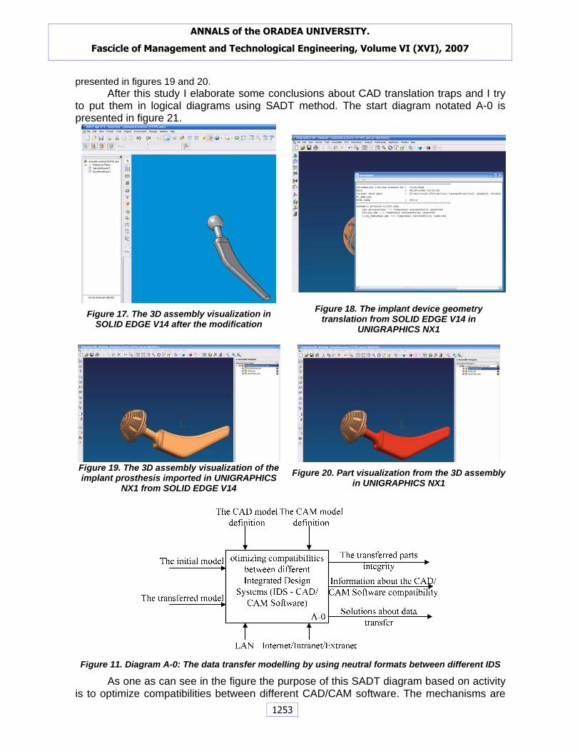
presented in figures 19 and 20. After this study I elaborate some conclusions about CAD translation traps and I try to put them in logical diagrams using SADT method. The start diagram notated A-0 is presented in figure 21.
Figure 17. The 3D assembly visualization in
SOLID EDGE V14 after the modification Figure 18. The implant device geometry
translation from SOLID EDGE V14 in UNIGRAPHICS NX1
Figure 19. The 3D assembly visualization of the implant prosthesis imported in UNIGRAPHICS
NX1 from SOLID EDGE V14 Figure 20. Part visualization from the 3D assembly
in UNIGRAPHICS NX1
Figure 11. Diagram A-0: The data transfer modelling by using neutral formats between different IDS
As one as can see in the figure the purpose of this SADT diagram based on activity is to optimize compatibilities between different CAD/CAM software. The mechanisms are
ANNALS of the ORADEA UNIVERSITY.
Fascicle of Management and Technological Engineering, Volume VI (XVI), 2007
1253
items such LAN and Internet/Extranet/Intranet; the inputs are: initial and the transferred model. The controls are items like the definitions of CAD and CAM model. With this entering, the inputs are transformed in outputs like: the transferred parts integrity, information about the CAD/CAM programs compatibility and the solutions about data transfer.
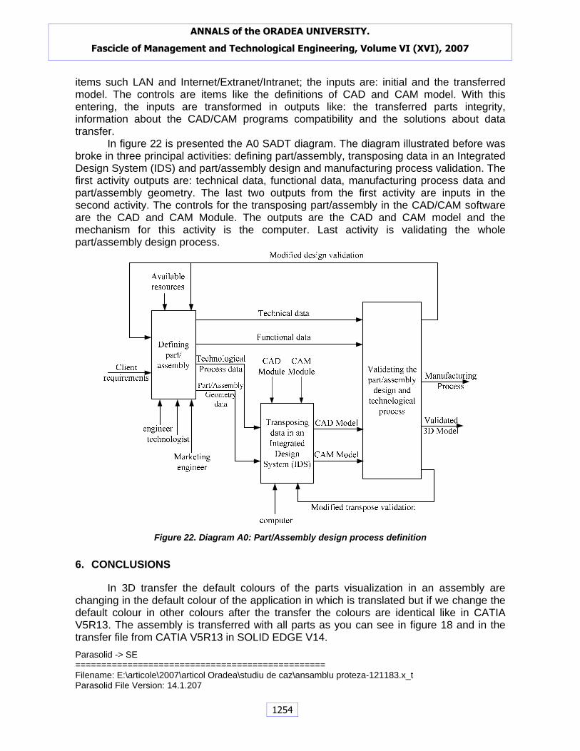
In figure 22 is presented the A0 SADT diagram. The diagram illustrated before was broke in three principal activities: defining part/assembly, transposing data in an Integrated Design System (IDS) and part/assembly design and manufacturing process validation. The first activity outputs are: technical data, functional data, manufacturing process data and part/assembly geometry. The last two outputs from the first activity are inputs in the second activity. The controls for the transposing part/assembly in the CAD/CAM software are the CAD and CAM Module. The outputs are the CAD and CAM model and the mechanism for this activity is the computer. Last activity is validating the whole part/assembly design process.
Figure 22. Diagram A0: Part/Assembly design process definition
6. CONCLUSIONS
In 3D transfer the default colours of the parts visualization in an assembly are changing in the default colour of the application in which is translated but if we change the default colour in other colours after the transfer the colours are identical like in CATIA V5R13. The assembly is transferred with all parts as you can see in figure 18 and in the transfer file from CATIA V5R13 in SOLID EDGE V14.
Parasolid -> SE ================================================ Filename: E:\articole\2007\articol Oradea\studiu de caz\ansamblu proteza-121183.x_t Parasolid File Version: 14.1.207
ANNALS of the ORADEA UNIVERSITY.
Fascicle of Management and Technological Engineering, Volume VI (XVI), 2007
1254

Begin Assembly 0 Total Parts : 3 Assemblies: 0 Solid Bodies: 3 Sheet Bodies: 0 ================================================ Processing Solid Body 1 of 3 Created SE Part File E:\ articole\2007\articol Oradea\studiu de caz\cap proteza.par Placing cap proteza.par:1 ================================================ Processing Solid Body 2 of 3 Created SE Part File E:\ articole\2007\articol Oradea\studiu de caz\rotula.par Placing rotula.par:1 ================================================ Processing Solid Body 3 of 3 Created SE Part File E:\articole\ articole\2007\articol Oradea\studiu de caz\tija_femurala.par Placing tija_femurala.par:1
The assembly can support modification by surface or deleted same of his parts but his base sketch can’t be modificated because the parts are known in those applications CAD/CAM as an imported part (figure 17).
In conclusion, to export files in STEP format must been accomplish the next conditions:
− For assemblies, confirm that all component files are in the same directory; − Make all geometry visible and selectable; − Remove unnecessary geometry, layers, annotation from the file(s); − Use tools available in the native system to validate geometry prior to export; − Ensure that the STEP translator can support the nature of the data to be
exchanged. The objective of STEP is to provide a neutral mechanism capable of describing
product data throughout the life cycle of a product that is independent from any particular software application or computer platform. With this comparative study between CAD transfer performances for different software I frame a solution using SADT technique to solve some problems that appear in virtual enterprise organizations using different Integrated Design System (IDS) from one department to another. The case study presented in the previous chapter is not finished. The finally results will be published when ready.
REFERENCES [1] Bucur, C.C., Ciobanu, L.F., Popa C.L.: Study about the Manufacturing Integration in the Design Phase
Using Several CAD-CAM Integration Systems Software, In Proc. of 1st International Conference “From Scientific Computing to Computational Engineering”, pp. 1195 – 1202, ISBN 960 – 530 – 071 – 0; Athens, Greece, 8 - 10 September, 2004
[2] Bucur, C.C., Ciobanu, L.F.: Data Transfer Between CAD-CAM-CAE Cooperative Systems, In Proc. of 7th Conference on Management of Innovative Technologies, MIT2004, M. Chircor and G. Dragoi editors, pp. 19 – 22, ISBN 973 – 700 – 028 – 5, Constanta, Romania, 4-5 October, 2004
[3] CADD-6.pdf, available from www.upfrontezine.com/eBooks/. Accessed at 2006-05-20 [4] Popescu D., Popa C.L., Ciobanu F.L.,. Grigoroiu G.E,. Bucur C.C: Îndrumar CAD CATIA V5R8, AIUS
editor, ISBN 973-700-011-0, Craiova, Romania, 2004 [5] SCRA, (2001). ISO 10303 STEP Application Handbook Version 2, Available
from:www.uspro.org/Free_Downloads/StepHandbookRequestForm.html. Accessed at 2004-10-16 [6] Sparling D. (2004) Requirements Specification Methods - Structured Analysis and Design Technique
(SADT), available at http://cctr.umkc.edu/~dsparling/cs457/sadt.html Accessed: 2004-11-20
ANNALS of the ORADEA UNIVERSITY.
Fascicle of Management and Technological Engineering, Volume VI (XVI), 2007
1255