CAD in the Aerospace Industry
70
EOT_RT_Sub_Template.ppt | 1/6/2009 | 1 BOEING is a trademark of Boeing Management Company. Copyright © 2009 Boeing. All rights reserved. CAD in the Aerospace Industry Thomas A. Grandine Senior Technical Fellow Platform Performance Technology
Transcript of CAD in the Aerospace Industry

EOT_RT_Sub_Template.ppt | 1/6/2009 | 1
BOEING is a trademark of Boeing Management Company.
Copyright © 2009 Boeing. All rights reserved.
CAD in the Aerospace Industry
Thomas A. GrandineSenior Technical FellowPlatform Performance Technology

Engineering, Operations & Technology | Boeing Research & Technology FaST | Platform Performance Technology
BRT_PPT_Template.ppt | 2Copyright © 2009 Boeing. All rights reserved.
My biography is pretty straightforward
• Born in Wisconsin in 1958
• Received a B.S. from Yale
in 1981
• Studied under Carl de Boor
and received a Ph.D. at
Wisconsin in 1985 for
“Computing with Simplex
Splines”
• Have worked for Boeing
since 1986

Engineering, Operations & Technology | Boeing Research & Technology FaST | Platform Performance Technology
BRT_PPT_Template.ppt | 3Copyright © 2009 Boeing. All rights reserved.
Boeing has three main business units
The Boeing
Company
BoeingCommercial Airplanes
BoeingDefense, Space &
Security
Engineering, Operations & Technology
1000
68,000
18,000
61,000
SSG BCC
Research and
Technology
4,000

Engineering, Operations & Technology | Boeing Research & Technology FaST | Platform Performance Technology
BRT_PPT_Template.ppt | 4Copyright © 2009 Boeing. All rights reserved.
The Applied Math group is organized by technical specialty
Geometry and Optimization
Computational Mathematics
Operations Research
Applied StatisticsMathematical
Modeling
Optimal sensor systems
Data management of complex products
Algorithms to characterize materials and structures
Design of composite materials
Computer-aided geometric design
Multidisciplinary design optimization
Optimization and optimal control
Multivariate data fitting
Reliability
Design of experiments
Statistical methods for engineering
Statistical quality assurance
Resource allocation, planning, scheduling
System of systems optimization
Data fusion
Stochastic, discrete and network optimization
Computational linear algebra
Differential and integral equations
Advanced engineering computing
Performance and scalability
• About 60 scientists, most with advanced degrees, about 2/3 PhDs• One Senior Technical Fellow, 7 Fellows, 14 Associate Fellows• Roughly 150 projects per year - Boeing programs, external customers, applied R&D

Engineering, Operations & Technology | Boeing Research & Technology FaST | Platform Performance Technology
BRT_PPT_Template.ppt | 5Copyright © 2009 Boeing. All rights reserved.
Who pays us for what?
Example: Develop targeting algorithms for the B-1 Lancer and Joint Direct Attack Munition
Example: Develop a Boeing-standard
design optimization system
Example: Write a C++ geometry software library
for the US NavyDirect
Investment
External

Engineering, Operations & Technology | Boeing Research & Technology FaST | Platform Performance Technology
BRT_PPT_Template.ppt | 6Copyright © 2009 Boeing. All rights reserved.
First “CAD” in aerospace is due to Liming, 1944
• Liming presented a vision for CAD in his 1944 book, Practical Analytic Geometry with Applications to Aircraft
• “While a graphic solution represents an approximate answer to a problem, the mathematical solution represents an exact answer; hence, the latter method is indispensable to securing accurately established data in a basic lofting development.“
• "Furthermore, as soon as fundamental basic data have been calculated and established by a system of analytic geometry techniques, a compactly organized body of basic equations is available for all subsequent calculations. A coordinated body of dimensional data is assured at all stages of the calculation process."
• "The nature of lofting calculations is such that analytic geometry is ideally adapted to the resolution of lofting problems. At the same time, since the loft represents a permanent source of master dimensional authority, analytic equations and formulas, systematically charted, constitute an easily established permanent source of such dimensions."
• ". . . the algebraic difficulties [in solving a 5 x 5 linear system of equations] are insurmountable from a practical point of view."

Engineering, Operations & Technology | Boeing Research & Technology FaST | Platform Performance Technology
BRT_PPT_Template.ppt | 7Copyright © 2009 Boeing. All rights reserved.
The value of interactive CAD is overstated
• Simpson’s 2004 study has profound implications*• Involved 35 Boeing test subjects
• Interactive delays had no effect on subjects’ performance
• Quality of answer correlated inversely with confidence of
designer
• Quality of answer correlated inversely with number of times
designer examined graphical display of design
• Quality of answer had no correlation with experience of
designer
*Simpson, T.W. and Meckesheimer, M., "Evaluation of a Graphical Design
Interface for Design Space Visualization," 45th AiAA/ASME/ASCE/AHS/ASC
Structures, Structural Dynamics & Materials Conference, April 9-22, AIAA-2004-163.
Engineering, Operations & Technology | Boeing Research & Technology FaST | Platform Performance Technology
BRT_PPT_Template.ppt | 8Copyright © 2009 Boeing. All rights reserved.
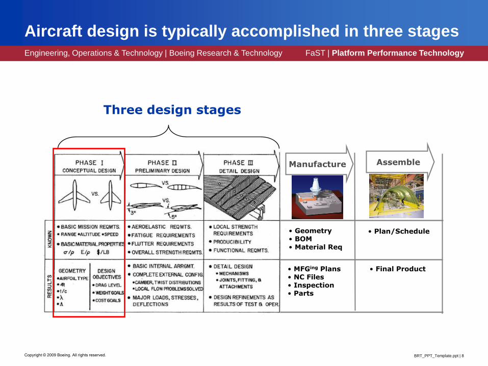
Aircraft design is typically accomplished in three stages
Manufacture Assemble
• Plan/Schedule• Geometry• BOM• Material Req
• Final Product• MFGing Plans• NC Files• Inspection• Parts
Three design stages

Engineering, Operations & Technology | Boeing Research & Technology FaST | Platform Performance Technology
BRT_PPT_Template.ppt | 9Copyright © 2009 Boeing. All rights reserved.
The first phase is conceptual design
• Mission requirements
determine design
objectives
• Conceptual design
problem: Determine best
combination of shapes and
sizes to meet these
requirements
• Vehicle Capability Goals
• Range (km) 14400
• Passengers 468
• Cruise speed (Mach) 0.9
• Altitude (m) 11000
• Take-off field length (m) 3100
• Cost / seat mile (US $) 0.065
• Flight control electric
• Noise footprint -53%
• Emissions (NOx) -75%
• Emissions (CO2) -50%

Engineering, Operations & Technology | Boeing Research & Technology FaST | Platform Performance Technology
BRT_PPT_Template.ppt | 10Copyright © 2009 Boeing. All rights reserved.
Modern jet transports are all similarly configured. . .
Boeing 757 & 767 Airbus A318
Tupolev 204

Engineering, Operations & Technology | Boeing Research & Technology FaST | Platform Performance Technology
BRT_PPT_Template.ppt | 11Copyright © 2009 Boeing. All rights reserved.
. . . but other design solutions are proposed all the time
Military designs have even more variability

Engineering, Operations & Technology | Boeing Research & Technology FaST | Platform Performance Technology
BRT_PPT_Template.ppt | 12Copyright © 2009 Boeing. All rights reserved.
Conceptual design requires balancing a lot of different design objectives
• Lots of historical data and
empirical rules
• Rules are usually
configuration specific
• Analysis can provide rough
ideas of sizing, weight,
performance, wing sweep
angles, etc.
• Shape often does not play
a role in the analysis
• Make best educated guess
of what will work best,
taking all the quantifiable
and non-quantifiable
objectives into account.
Difficulty: Topological design exploration is hard

Engineering, Operations & Technology | Boeing Research & Technology FaST | Platform Performance Technology
BRT_PPT_Template.ppt | 13Copyright © 2009 Boeing. All rights reserved.
The output of conceptual design is a configuration

Engineering, Operations & Technology | Boeing Research & Technology FaST | Platform Performance Technology
BRT_PPT_Template.ppt | 14Copyright © 2009 Boeing. All rights reserved.
A significant trap occurs by placing too much value on initial guesses and existing baselines
• Human behavior relies on
“anchoring.”*
• Anchoring occurs
whenever estimates based
on incomplete or
inaccurate information are
made
• Human nature discourages
adequate adjustments to
anchor points
• Awareness of the
anchoring bias does not
eliminate its effect**
*Kahneman, Slovic, Tversky, Judgment under uncertainty: Heuristics and biases, 1982.**Gilovich, Griffin, Kahneman, Heuristics and Biases: The Psychology of Intuitive Judgment, 2002
0
20
40
60
80
1st
Group
2nd
Group
Spinner
Estimate
Experimental results predictingAfrican U.N. membership

Engineering, Operations & Technology | Boeing Research & Technology FaST | Platform Performance Technology
BRT_PPT_Template.ppt | 15Copyright © 2009 Boeing. All rights reserved.
The original 737 re-engine project demonstrates this

Engineering, Operations & Technology | Boeing Research & Technology FaST | Platform Performance Technology
BRT_PPT_Template.ppt | 16Copyright © 2009 Boeing. All rights reserved.
Preliminary design follows conceptual design
Manufacture Assemble
• Plan/Schedule• Geometry• BOM• Material Req
• Final Product• MFGing Plans• NC Files• Inspection• Parts
Three design stages

Engineering, Operations & Technology | Boeing Research & Technology FaST | Platform Performance Technology
BRT_PPT_Template.ppt | 17Copyright © 2009 Boeing. All rights reserved.
Preliminary design refines the basic shapes and sizes
• The output at this stage includes• Complete external shape definition (OML = outer mold line)
• Complete wing definition
• Major structural boxes and components
• Basic internal arrangement
• Other considerations
• Cost is mostly locked in at this stage, so preliminary
design needs to be done very carefully

Engineering, Operations & Technology | Boeing Research & Technology FaST | Platform Performance Technology
BRT_PPT_Template.ppt | 18Copyright © 2009 Boeing. All rights reserved.
Traditional preliminary design isn’t competitive in the 21st century
Change
geometry
Engineering
Analysis
Geometric ModelGrid
Start
Too
much
drag
This is very hard!? ?
?
?
Engineering, Operations & Technology | Boeing Research & Technology FaST | Platform Performance Technology
BRT_PPT_Template.ppt | 19Copyright © 2009 Boeing. All rights reserved.
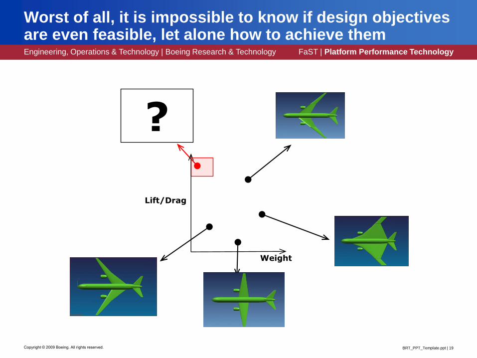
Worst of all, it is impossible to know if design objectives are even feasible, let alone how to achieve them
?
Weight
Lift/Drag

Engineering, Operations & Technology | Boeing Research & Technology FaST | Platform Performance Technology
BRT_PPT_Template.ppt | 20Copyright © 2009 Boeing. All rights reserved.
Multidisciplinary design optimization (MDO) offers a more systematic approach
nx
x
x
2
1
my
y
y
2
1
Design Explorer
Design Parameters
ConstraintFunctionValues
ObjectiveFunctionValues
sweepcambertwistmax thrustcrown htlength...
Geometry Generator
MDAAnalysis
Code
AnalysisCode
AnalysisCode
AnalysisCode
dragliftweightsheatingnoiseEM...
Engineering, Operations & Technology | Boeing Research & Technology FaST | Platform Performance Technology
BRT_PPT_Template.ppt | 21Copyright © 2009 Boeing. All rights reserved.
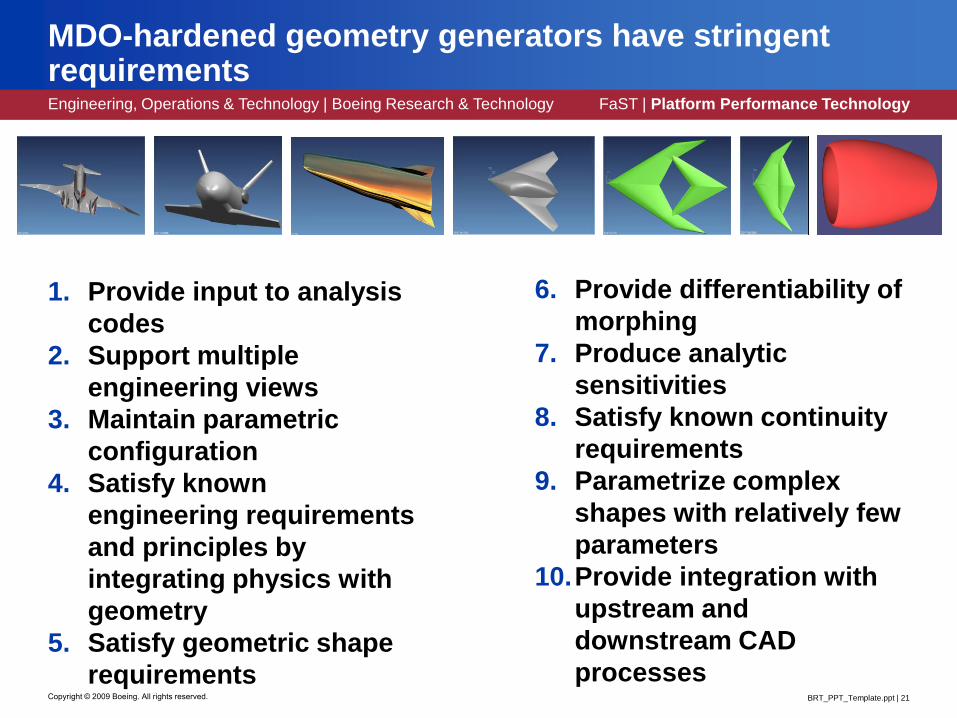
MDO-hardened geometry generators have stringent requirements
1. Provide input to analysis
codes
2. Support multiple
engineering views
3. Maintain parametric
configuration
4. Satisfy known
engineering requirements
and principles by
integrating physics with
geometry
5. Satisfy geometric shape
requirements
6. Provide differentiability of
morphing
7. Produce analytic
sensitivities
8. Satisfy known continuity
requirements
9. Parametrize complex
shapes with relatively few
parameters
10.Provide integration with
upstream and
downstream CAD
processes

Engineering, Operations & Technology | Boeing Research & Technology FaST | Platform Performance Technology
BRT_PPT_Template.ppt | 22Copyright © 2009 Boeing. All rights reserved.
(1) Provide input to analysis codes
• Analysis
geometry and
Build geometry
are not the same
• Analysis
geometry requires
no gaps or
overlaps, even
when they are
present in the
actual product
Engineering, Operations & Technology | Boeing Research & Technology FaST | Platform Performance Technology
BRT_PPT_Template.ppt | 23Copyright © 2009 Boeing. All rights reserved.
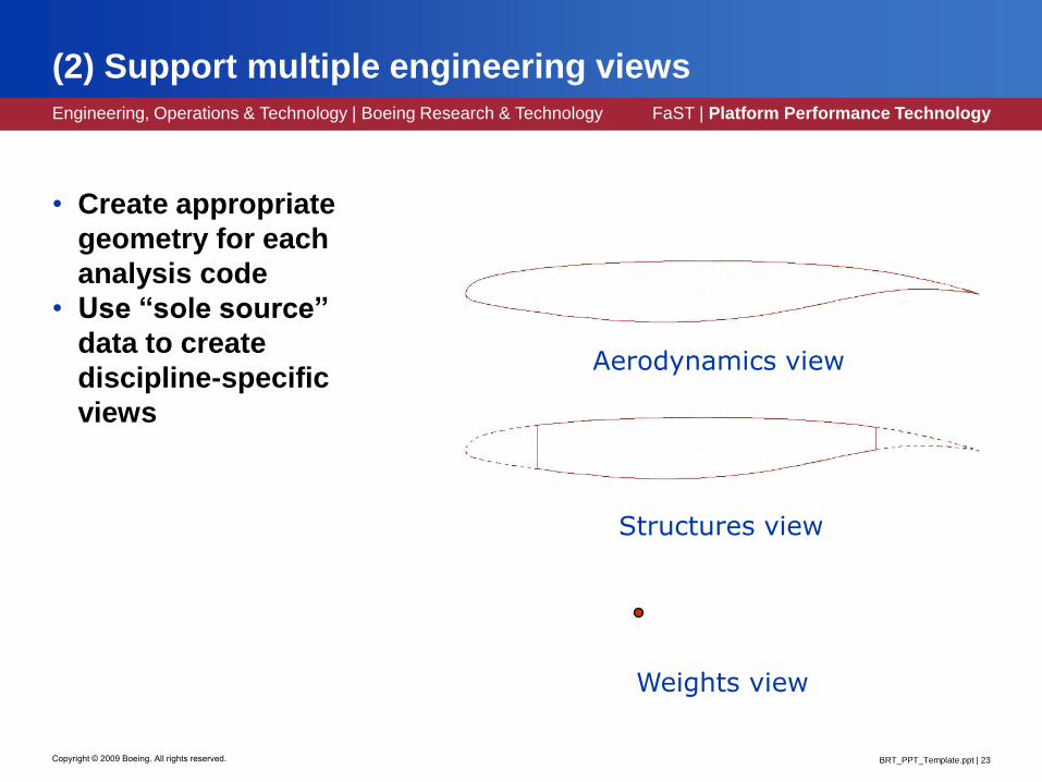
(2) Support multiple engineering views
• Create appropriate
geometry for each
analysis code
• Use “sole source”
data to create
discipline-specific
views
Aerodynamics view
Structures view
Weights view

Engineering, Operations & Technology | Boeing Research & Technology FaST | Platform Performance Technology
BRT_PPT_Template.ppt | 24Copyright © 2009 Boeing. All rights reserved.
(3) Maintain parametric configuration
Cr
b/2
Cr
L ¼c
L le
L te
This is a good parameterizationIt always produces a good wing plan form
This is BAD
Parametrizations should always maintain sensible configurations

Engineering, Operations & Technology | Boeing Research & Technology FaST | Platform Performance Technology
BRT_PPT_Template.ppt | 25Copyright © 2009 Boeing. All rights reserved.
(4) Satisfy engineering requirements and principles by integrating physics with geometry
Example: Isentropic high speed inlets
Flow speed decreases
and pressure increases
as it turns
Direction of flow
Shock and Mach wave angles
increase as flow speed decreases
Cowl lip point
The engine should capture all the compression waves without spillage

Engineering, Operations & Technology | Boeing Research & Technology FaST | Platform Performance Technology
BRT_PPT_Template.ppt | 26Copyright © 2009 Boeing. All rights reserved.
(5) Satisfy geometric shape requirements
• No unwanted
inflection points
• Satisfy component
specific geometry
requirements
• Control of curvature
distribution
Hiliteradius
Exitangle
+ Additional curve shaping parameters
Hilitecurvature
Parametric variants of this nacelle are also nacelles
Section must match crown aft of here
Hiliteradius
+ Additional curve shaping parameters
Hilitecurvature
Nacelle crown
Nacelle keel, MHB

Engineering, Operations & Technology | Boeing Research & Technology FaST | Platform Performance Technology
BRT_PPT_Template.ppt | 27Copyright © 2009 Boeing. All rights reserved.
(6) Provide differentiability of morphing
• Small changes in
design parameters
should not produce
large changes in
geometry
• “Open source”
algorithms required to
create program
specific workarounds
to inevitable problems

Engineering, Operations & Technology | Boeing Research & Technology FaST | Platform Performance Technology
BRT_PPT_Template.ppt | 28Copyright © 2009 Boeing. All rights reserved.
Phenomenon can easily be demonstrated. . .
Small change (0.0001”) causes curve to flip over
Curve is about 5” long

Engineering, Operations & Technology | Boeing Research & Technology FaST | Platform Performance Technology
BRT_PPT_Template.ppt | 29Copyright © 2009 Boeing. All rights reserved.
. . . in any CAD system one chooses

Engineering, Operations & Technology | Boeing Research & Technology FaST | Platform Performance Technology
BRT_PPT_Template.ppt | 30Copyright © 2009 Boeing. All rights reserved.
Morphing discontinuities introduce discontinuities in analysis results
Center of Gravity
0.57
0.575
0.58
0.585
0.59
0.595
0.6
0.605
0 0.2 0.4 0.6 0.8 1
Position of Pad
Z c
om
po
nen
t o
f C
G
Not Continuous
Source Vadim Shapiro:http://sal-cnc.me.wisc.edu/Research/parametric/limits.html
We don’t wantthis!

Engineering, Operations & Technology | Boeing Research & Technology FaST | Platform Performance Technology
BRT_PPT_Template.ppt | 31Copyright © 2009 Boeing. All rights reserved.
(7) Produce analytic sensitivities
• One promising approach
due to Chen, Freytag, and
Shapiro works for all
analysis functions of the
form
• Key idea: Make use of
solid modeling and track all
changes through primitives
dvvbfbF ),()(
The math works even in the
presence of topology changes!

Engineering, Operations & Technology | Boeing Research & Technology FaST | Platform Performance Technology
BRT_PPT_Template.ppt | 32Copyright © 2009 Boeing. All rights reserved.
How would one compute the derivative of the center of mass with respect to wing sweep?

Engineering, Operations & Technology | Boeing Research & Technology FaST | Platform Performance Technology
BRT_PPT_Template.ppt | 33Copyright © 2009 Boeing. All rights reserved.
This idea has been partially implemented at Boeing
• Chen, Freytag, and
Shapiro’s main result:
• In terms of parametric loft
components, this becomes
)(bk
k
kb
f
b
f
db
dF
k
bk S
k Nb
Sf
b
f
db
dF
k
)(
deriv = 0.0
for face in Aofb:
Skwrtb = . . .
deriv += Skwrtb.Flux (face)
The center of mass will move
aft 1.4662” for every additional
degree of wing sweep
Engineering, Operations & Technology | Boeing Research & Technology FaST | Platform Performance Technology
BRT_PPT_Template.ppt | 34Copyright © 2009 Boeing. All rights reserved.
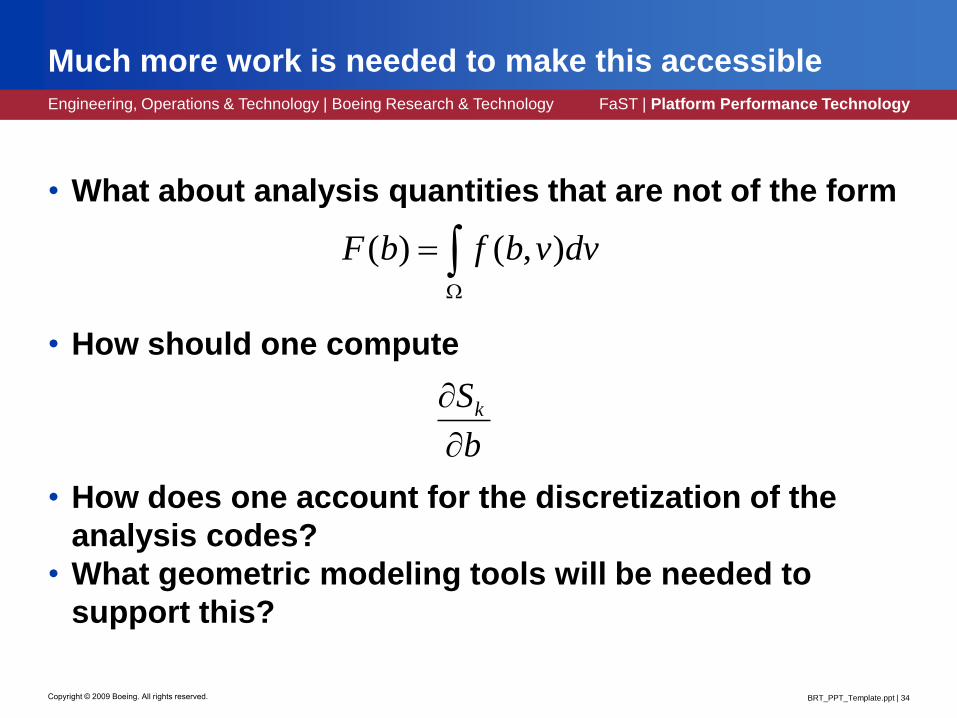
Much more work is needed to make this accessible
• What about analysis quantities that are not of the form
• How should one compute
• How does one account for the discretization of the
analysis codes?
• What geometric modeling tools will be needed to
support this?
dvvbfbF ),()(
b
Sk

Engineering, Operations & Technology | Boeing Research & Technology FaST | Platform Performance Technology
BRT_PPT_Template.ppt | 35Copyright © 2009 Boeing. All rights reserved.
(8) Satisfy known continuity requirements
Example: Curvature continuity for fillets and blends needed for electromagnetic applications

Engineering, Operations & Technology | Boeing Research & Technology FaST | Platform Performance Technology
BRT_PPT_Template.ppt | 36Copyright © 2009 Boeing. All rights reserved.
(9) Parametrize complex shapes with relatively few parameters
• Strings of input
points are not
effective
parameters
• Large changes in
any one
contributes
undesirable, high-
frequency
changes

Engineering, Operations & Technology | Boeing Research & Technology FaST | Platform Performance Technology
BRT_PPT_Template.ppt | 37Copyright © 2009 Boeing. All rights reserved.
(10) Provide integration with upstream and downstream CAD processes

Engineering, Operations & Technology | Boeing Research & Technology FaST | Platform Performance Technology
BRT_PPT_Template.ppt | 38Copyright © 2009 Boeing. All rights reserved.
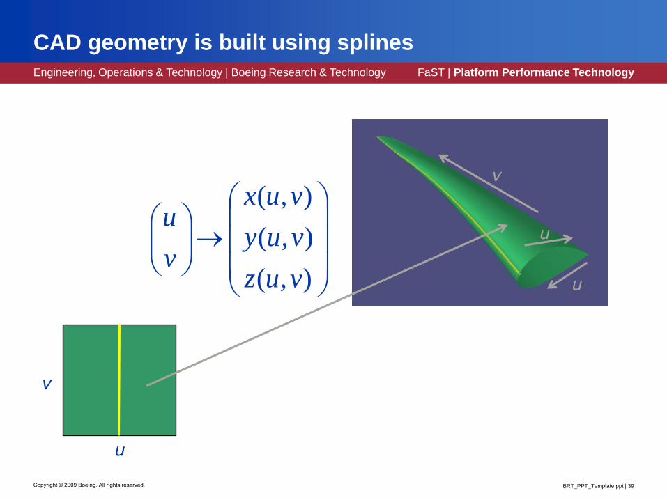
Geometric models are almost always built with splines
• Splines are piecewise polynomial functions
• The linear space of functions they live in is called
it1it 1it 2it 3it
Engineering, Operations & Technology | Boeing Research & Technology FaST | Platform Performance Technology
BRT_PPT_Template.ppt | 39Copyright © 2009 Boeing. All rights reserved.
u
v
u
u
v
),(
),(
),(
vuz
vuy
vux
v
u
CAD geometry is built using splines

Engineering, Operations & Technology | Boeing Research & Technology FaST | Platform Performance Technology
BRT_PPT_Template.ppt | 40Copyright © 2009 Boeing. All rights reserved.
B-splines are used to represent splines
• Any function in can be represented as
n
j
kjj xBxs0
, )()(

Engineering, Operations & Technology | Boeing Research & Technology FaST | Platform Performance Technology
BRT_PPT_Template.ppt | 41Copyright © 2009 Boeing. All rights reserved.
B-splines make excellent finite elements
• Given a differential equation
• Compute an approximation solution
• Advantages include• High order accuracy
• Smooth approximation
),()( xufuL
j
jj xBxu )()(ˆ

Engineering, Operations & Technology | Boeing Research & Technology FaST | Platform Performance Technology
BRT_PPT_Template.ppt | 42Copyright © 2009 Boeing. All rights reserved.
Boeing’s B-spline ODE solver has a long history
• Major improvements• 1988 – First FORTRAN version [Grandine]
• 1989 – Autogeneration of Gauss points [Epton]
• 1991 – Improved adaptivity algorithm [Bieterman]
• 1995 – LAPACK’s banded solver instead of SolveBlok [Klein]
• 2001 – Code rewritten in C [Pierce]
• 2004 – Improved Newton convergence [Ettinger]
• 2009 – Leveraged decoupling for IVPs [Klein]
• Many minor improvements along the way, too• 6 formal revisions since January, 2009
• 37 formal revisions since 2001
• Current version dated 10 February, 2010

Engineering, Operations & Technology | Boeing Research & Technology FaST | Platform Performance Technology
BRT_PPT_Template.ppt | 43Copyright © 2009 Boeing. All rights reserved.
Our method of choice is de Boor – Swartz collocation
• Use B-splines as finite elements
• Approximate ODE solution by solving
j
jjBu
uufu
)()(
))('),(,()("
i
iiii uufu
))('),(,()("
are the Gauss-Legendre points
over each polynomial piece
Engineering, Operations & Technology | Boeing Research & Technology FaST | Platform Performance Technology
BRT_PPT_Template.ppt | 44Copyright © 2009 Boeing. All rights reserved.
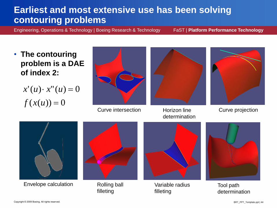
Earliest and most extensive use has been solving contouring problems
• The contouring
problem is a DAE
of index 2:
0))((
0)(")('
uxf
uxux
Curve intersection Curve projectionHorizon line
determination
Tool path
determination
Variable radius
filleting
Rolling ball
filleting
Envelope calculation

Engineering, Operations & Technology | Boeing Research & Technology FaST | Platform Performance Technology
BRT_PPT_Template.ppt | 45Copyright © 2009 Boeing. All rights reserved.
Curves can be parametrized in terms of curvature
• Desired curvature
distributions can be
integrated
. . . can be integrated
to produce . . .
'
')(
"
"
x
ys
y
x

Engineering, Operations & Technology | Boeing Research & Technology FaST | Platform Performance Technology
BRT_PPT_Template.ppt | 46Copyright © 2009 Boeing. All rights reserved.
Some high speed inlets need to satisfy a “shock on lip” condition
Example: Isentropic high speed inlets
Flow speed decreases
and pressure increases
as it turns
Direction of flow
Shock and Mach wave angles
increase as flow speed decreases
Cowl lip point
The engine should capture all the compression waves without spillage
Engineering, Operations & Technology | Boeing Research & Technology FaST | Platform Performance Technology
BRT_PPT_Template.ppt | 47Copyright © 2009 Boeing. All rights reserved.
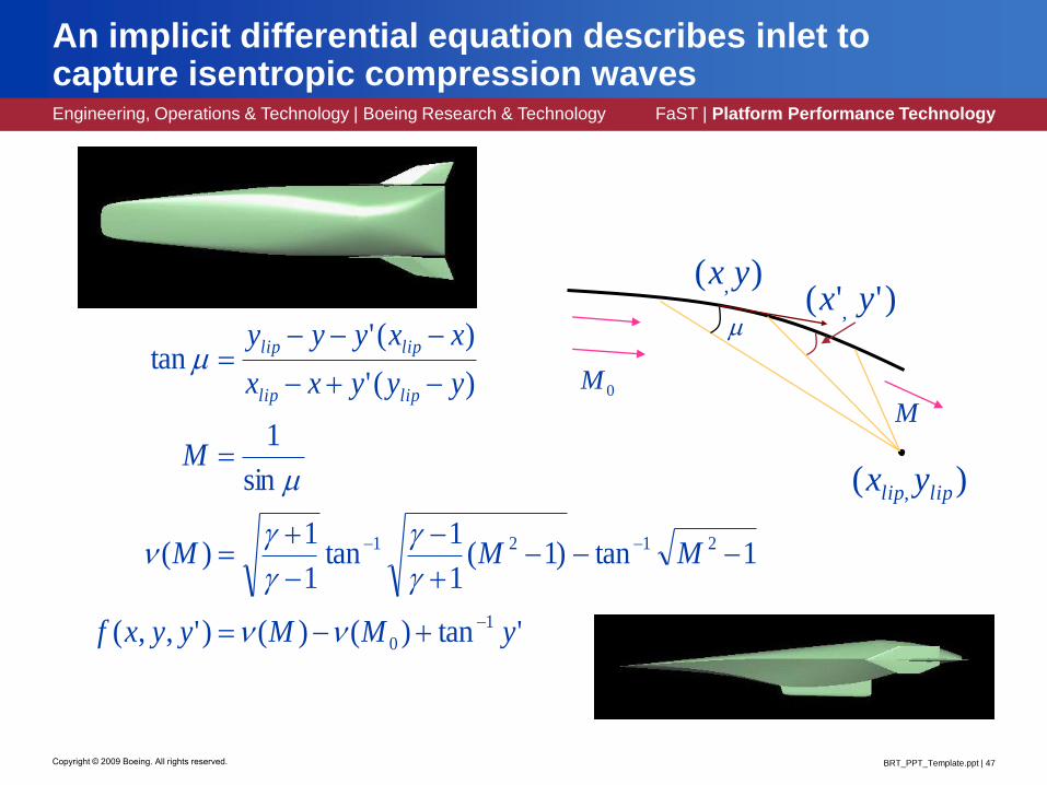
An implicit differential equation describes inlet to capture isentropic compression waves
'tan)()()',,(
1tan)1(1
1tan
1
1)(
sin
1
)('
)('tan
1
0
2121
yMMyyxf
MMM
M
yyyxx
xxyyy
liplip
liplip
0M
)( , liplip yx
M
)( , yx)''( , yx

Engineering, Operations & Technology | Boeing Research & Technology FaST | Platform Performance Technology
BRT_PPT_Template.ppt | 48Copyright © 2009 Boeing. All rights reserved.
B-spline finite elements can be used to correct lofts for computed deformations
• Solutions to the linearized
structural analysis problem
introduce unwanted
stretching of material
• The combination of the two
different discretizations
sometimes leads to noisy
computed deflections on
the aero mesh
• Updating the mesh instead
of the loft sometimes
produces invalid deformed
meshes
Linear deformation with
stretching
Corrected deformation

Engineering, Operations & Technology | Boeing Research & Technology FaST | Platform Performance Technology
BRT_PPT_Template.ppt | 49Copyright © 2009 Boeing. All rights reserved.
How can we reacquire some of the lost nonlinearity?
• Basic idea: Merge the deformations together with the
intrinsic geometry of the undeflected curve
• Where• p = Original curve
• d = Computed deflections
• q = Corrected, deflected curve
)""(''
''''" dp
pq
pqpqq
TT

Engineering, Operations & Technology | Boeing Research & Technology FaST | Platform Performance Technology
BRT_PPT_Template.ppt | 50Copyright © 2009 Boeing. All rights reserved.
The model can be extended to surfaces

Engineering, Operations & Technology | Boeing Research & Technology FaST | Platform Performance Technology
BRT_PPT_Template.ppt | 51Copyright © 2009 Boeing. All rights reserved.
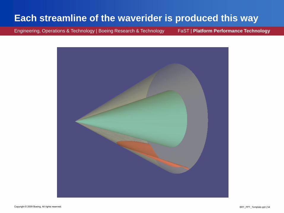
B-spline finite elements can be used to loft waveriders
• A waverider is a
lifting surface which
rides on the shock
wave created by its
own leading edge in
supersonic flight• First developed by
Terence Nonweiler in
1951
• Only production
design to use
waveriders was XB-
70 in 1960s

Engineering, Operations & Technology | Boeing Research & Technology FaST | Platform Performance Technology
BRT_PPT_Template.ppt | 52Copyright © 2009 Boeing. All rights reserved.
The Taylor-MacColl equation models conical flow
• Start with the Navier Stokes
equation
• Assume• Inviscid flow
• Circumferentially
symmetric flow
• Irrotational flow
• Steady flow
• In spherical coordinates:
u
uuu
uuuuu
)'1(2
1'
)cot')('1(2
1
)("222
22
u
)(u)(' u

Engineering, Operations & Technology | Boeing Research & Technology FaST | Platform Performance Technology
BRT_PPT_Template.ppt | 53Copyright © 2009 Boeing. All rights reserved.
Generate streamline by solving another ODE
)(')()(
)(')()()('
arctan
uxyxu
xuuxyxy
x
y
u
00)( yxy
Note: All solutions are self-similar
Engineering, Operations & Technology | Boeing Research & Technology FaST | Platform Performance Technology
BRT_PPT_Template.ppt | 54Copyright © 2009 Boeing. All rights reserved.
Each streamline of the waverider is produced this way

Engineering, Operations & Technology | Boeing Research & Technology FaST | Platform Performance Technology
BRT_PPT_Template.ppt | 55Copyright © 2009 Boeing. All rights reserved.
Can also loft Busemann inlets by tracing streamlines
u

Engineering, Operations & Technology | Boeing Research & Technology FaST | Platform Performance Technology
BRT_PPT_Template.ppt | 56Copyright © 2009 Boeing. All rights reserved.
Detail design is the most expensive design stage
Manufacture Assemble
• Plan/Schedule• Geometry• BOM• Material Req
• Final Product• MFGing Plans• NC Files• Inspection• Parts
Three design stages

Engineering, Operations & Technology | Boeing Research & Technology FaST | Platform Performance Technology
BRT_PPT_Template.ppt | 57Copyright © 2009 Boeing. All rights reserved.
Detail design is what most people think of as design
• Geometry models for the
entire airplane are created
in this stage
• Commercial CAD/CAM
systems are preeminent
• Little scope for systematic
design at the vehicle level
remains, but individual
components are frequently
optimized
• Analysis of individual
components is more
common than system or
vehicle level analysis

Engineering, Operations & Technology | Boeing Research & Technology FaST | Platform Performance Technology
BRT_PPT_Template.ppt | 58Copyright © 2009 Boeing. All rights reserved.
CAD has helped reduce the need for physical prototypes
• B2707 Supersonic
Transport (1966-1971)
• Prototype made out of
wood!
• Cost: Several million US$
(in 1970)
• Elimination of any physical
prototyping
• Early interference detection
• > 50% reduction of
engineering change
requests, rework and error
• Alignment to within .023”
versus .5” previously (20 x
better)
NowThen

Engineering, Operations & Technology | Boeing Research & Technology FaST | Platform Performance Technology
BRT_PPT_Template.ppt | 59Copyright © 2009 Boeing. All rights reserved.
Manufacturing and assembly will be covered later
Manufacture Assemble
• Plan/Schedule• Geometry• BOM• Material Req
• Final Product• MFGing Plans• NC Files• Inspection• Parts

Engineering, Operations & Technology | Boeing Research & Technology FaST | Platform Performance Technology
BRT_PPT_Template.ppt | 60Copyright © 2009 Boeing. All rights reserved.
Challenge #1: Actual parts are not rigid
Issues:
• Part growth during assembly
• Sagging
• As built shape is different from in-
flight shape
• Thermal effects (several models to
represent engine)
• Warpage due to internal stresses
• Current CAD technology does not
model dynamic structures very
well
The yellow thing is part of a wingNote the person in the back
A floppy structure
STOCK
PART
Warped
?

Engineering, Operations & Technology | Boeing Research & Technology FaST | Platform Performance Technology
BRT_PPT_Template.ppt | 61Copyright © 2009 Boeing. All rights reserved.
Challenge #2: What’s the best way to customize material properties?
Preheats, lays down, & cuts the material
Part is built up with tape and thread

Engineering, Operations & Technology | Boeing Research & Technology FaST | Platform Performance Technology
BRT_PPT_Template.ppt | 62Copyright © 2009 Boeing. All rights reserved.
787 fuselage sections are made this way
source: http://www.boeing.com/news/frontiers/archive/2004/may/i_ca3.htmlhttp://www.boeing.com/news/releases/2005/photorelease/q2/pr_050613h2.html
Then baked
Thermal effects/warpage after it cools
Desk
Tape is wound over a barrel
Person
787 Fuselage

Engineering, Operations & Technology | Boeing Research & Technology FaST | Platform Performance Technology
BRT_PPT_Template.ppt | 63Copyright © 2009 Boeing. All rights reserved.
Note the discrete nature of the surfaces in this part
Source: Personal pictureFuture of flight museum , Everett, WA
Note the pad up
~50layers
Engineering, Operations & Technology | Boeing Research & Technology FaST | Platform Performance Technology
BRT_PPT_Template.ppt | 64Copyright © 2009 Boeing. All rights reserved.
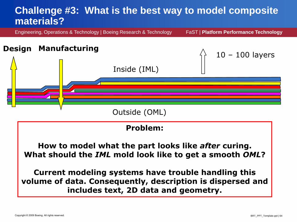
Challenge #3: What is the best way to model composite materials?
Problem:
How to model what the part looks like after curing.What should the IML mold look like to get a smooth OML?
Current modeling systems have trouble handling this volume of data. Consequently, description is dispersed and
includes text, 2D data and geometry.
10 – 100 layersDesign
Outside (OML)
Inside (IML)
Manufacturing

Engineering, Operations & Technology | Boeing Research & Technology FaST | Platform Performance Technology
BRT_PPT_Template.ppt | 65Copyright © 2009 Boeing. All rights reserved.
The future may lie with direct manufacturing
Flavors:• Layered manufacturing • Additive manufacturing • Rapid manufacturing (RM) • Direct digital manufacturing (DDM) • 3D Printing • Generative manufacturing • Rapid prototyping • Selective Laser Sintering (SLS) • Selective Laser Melting (SLM) • Fused Deposition Modeling (FDM) • Electron Beam Melting (EBM) • Stereo-Lithography Apparatus (SLA) • Laser Engineered Net Shape (LENS) • Laminate Object Manufacturing (LOM)
Lots of new methods being developed

Engineering, Operations & Technology | Boeing Research & Technology FaST | Platform Performance Technology
BRT_PPT_Template.ppt | 66Copyright © 2009 Boeing. All rights reserved.
Direct manufacturing is widely applicable
Complex parts “Impossible” parts
“Plastic” parts(Nylon, PEEK, …)
Molds for complex casting
MetalsBiologicals
(bone & bladder scaffolds, teeth, …)

Engineering, Operations & Technology | Boeing Research & Technology FaST | Platform Performance Technology
BRT_PPT_Template.ppt | 67Copyright © 2009 Boeing. All rights reserved.
Huge opportunities exist for direct manufacturing
• Production:• Eliminate non-recurring
tooling costs• Lower recurring unit part
costs• Faster part delivery times• Supplier flexibility• Direct fabrication (in some
cases):• 50% Cost Reduction• 67% Cycle Time Reduction at
Minimum
• Product:• Reduced part count and
weight• Lower inventory and
transportation costs• Improved Life Cycle Product
Costs
• Future• Battle field spares• Heterogeneous materials• Sensor embedding
• Challenge #4:• Not as strong (yet)• Not as accurate (yet)• Not for high volume• Size limits
DM parts in F 18

Engineering, Operations & Technology | Boeing Research & Technology FaST | Platform Performance Technology
BRT_PPT_Template.ppt | 68Copyright © 2009 Boeing. All rights reserved.
New materials and manufacturing techniques continue to open up new challenges
• How to make best use of “engineered anisotropic material”
• How can we generate the optimal shape AND material properties?
• Also…want to certify the processto avoid non destructive testing
repeatable & reliable processes
Optimal shape
Optimal microstructure
…with…

Engineering, Operations & Technology | Boeing Research & Technology FaST | Platform Performance Technology
BRT_PPT_Template.ppt | 69Copyright © 2009 Boeing. All rights reserved.
Huge challenges remain
• Geometric design is not a solved problem!
• How to best exploit new manufacturing processes?
• How to best exploit tailored materials?
Back to the future?Our first “manufactured” materials:
Wood & cloth!

EOT_RT_Sub_Template.ppt | 70Copyright © 2009 Boeing. All rights reserved.