CABRI GEOMETRYº II - Texas Instruments · Regular Polygon ... Becoming familiar with these items...
136
CABRI GEOMETRY ë II Guidebook for Macintosh ë , Windows ë , and MS-DOS ë
Transcript of CABRI GEOMETRYº II - Texas Instruments · Regular Polygon ... Becoming familiar with these items...
C A B R I G E O M E T R Y ë I I
Guidebook for Macintoshë, Windowsë, and MS-DOSë
Important
Texas Instruments makes no warranty, either expressed or implied, including but not limited to anyimplied warranties of merchantability and fitness for a particular purpose, regarding any programs or bookmaterials and makes such materials available solely on an “as-is” basis.
In no event shall Texas Instruments be liable to anyone for special, collateral, incidental, or consequentialdamages in connection with or arising out of the purchase or use of these materials, and the sole andexclusive liability of Texas Instruments, regardless of the form of action, shall not exceed the purchaseprice of this equipment. Moreover, Texas Instruments shall not be liable for any claim of any kindwhatsoever against the use of these materials by any other party.
Permission to Print
Permission is hereby granted to teachers to reprint or photocopy in classroom, workshop, or seminarquantities the pages or sheets in this work that carry a Texas Instruments copyright notice. These pagesare designed to be reproduced by teachers for use in their classes, workshops, or seminars with theaccompanying Cabri Geometry II software, provided each copy made shows the copyright notice. Suchcopies may not be sold and further distribution is expressly prohibited. Except as authorized above, priorwritten permission must be obtained from Texas Instruments Incorporated to reproduce or transmit thiswork or portions thereof in any other form or by any other electronic or mechanical means, including anyinformation storage or retrieval system, unless expressly permitted by federal copyright law. Addressinquiries to Texas Instruments Incorporated, 7800 Banner Drive, Dallas, TX 75251, M/S 3918, Attention:Manager, Business Services.
TI Product and Services Information
For more information about TI products and services, contact TI by e-mail or visit the TI calculator homepage on the world-wide web.
e-mail address: [email protected]
internet address: http://www.ti.com/calc
Cabri Geometry II is a trademark of Université Joseph Fourier.Macintosh is a registered trademark of Apple Computer Corporation Incorporated.MS-DOS and Windows are registered trademarks of Microsoft Corporation.PostScript is a registered trademark of Adobe Systems Incorporated.
1997, 1999 by Texas Instruments Incorporated. All rights reserved.
C A B R I G E O M E T R Y I I
Guidebookfor Macintoshë, Windowsë,and MS-DOSë
Dive into Geometry
Copying permitted provided TI copyright notice is included© 1997, 1999 Texas Instruments Incorporated
About Cabri Geometry II
Cabri Geometry II lets you construct and explore geometric objects interactively.Jean-Marie Laborde and Franck Bellemain developed Cabri Geometry II at the Institutd'Informatique et Mathématiques Appliquées de Grenoble (IMAG), a research lab at the UniversitéJoseph Fourier in Grenoble, France, in cooperation with the Centre National de la RechercheScientifique (CNRS) and Texas Instruments.
Texas Instruments, the publisher for Cabri Geometry II in the United States and Canada, is pleasedto bring computer-based geometry to classrooms. The geometric foundation of this easy-to-usesoftware encourages exploring and conjecturing—from simple shapes to advanced projective andhyperbolic geometry.
About the Developers
Jean-Marie Laborde is founder and Research Director of Laboratoire de Structures Discrètes et deDidactique (LSD2), a research laboratory within IMAG. He graduated in mathematics at ÈcoleNormale Supérieure in Paris in 1969. He earned a Ph.D. (Thèse d'État) in computer science at theUniversity of Grenoble in 1977. Jean-Marie began work on the Cabri II project in 1981 as anenvironment for graph theory. He has devoted his research efforts to the use of geometric methodsfor the study of different classes of graphs, especially hypercubes.
Franck Bellemain earned a Ph.D. in mathematics at the Université Joseph Fourier in 1992. Hebegan work on the Cabri II project in 1986 and is responsible for writing several versions of thesoftware for Macintosh, PC-compatible, and Japanese computers. His research and thesis havebeen devoted to the use of technology in the classroom.
Cabri Geometry II Features
¦ Includes interactive analytic, transformational, and Euclidean geometry.
¦ Allows intuitive construction of points, lines, triangles, polygons, circles, and other basicobjects.
¦ Translates, dilates, and rotates geometric objects around geometric centers or specified pointsplus reflection, symmetry, and inverse of the objects.
¦ Constructs conics easily, including ellipses and hyperbolas.
¦ Explores advanced concepts in projective and hyperbolic geometry.
¦ Annotates and measures figures (with automatic updating).
¦ Uses both Cartesian and polar coordinates.
¦ Provides for user display of the equations of geometric objects, including lines, circles,ellipses, and coordinates of points.
¦ Allows the user to create macros for frequently repeated constructions.
¦ Lets the teacher configure tool menus to focus student activities.
¦ Checks geometric properties to test hypotheses based on Euclid’s five postulates.
¦ Hides objects used in constructions to reduce screen clutter.
¦ Differentiates objects through the use of paint-like color and line palettes.
¦ Computes a locus continuously.
¦ Illustrates the dynamic characteristics of figures through animation.
¦ Allows the user to save drawings and macros to disk.
¦ Opens geometry constructions created on the TI-92.
¦ Provides one square meter of full-size work space, and prints the 8.5 by 11.0 inches (21.59 by27.94 cm) drawing area.
iiiCopying permitted provided TI copyright notice is included© 1997, 1999 Texas Instruments Incorporated
Table of Contents
About this Guidebook .................................................................. vi
CHAPTER 1: LEARNING THE BASICS ............................................. 1–1First Steps............................................................................. 1–2Constructing Objects ................................................................... 1–10
CHAPTER 2: USING THE MENUS ................................................... 2–1File Menu ............................................................................. 2–2Edit Menu ............................................................................. 2–5Options Menu.......................................................................... 2–7Help Menu............................................................................. 2–12
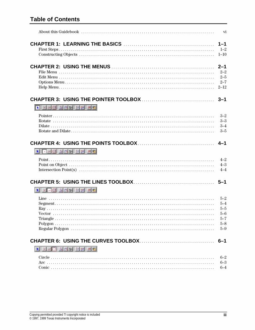
CHAPTER 3: USING THE POINTER TOOLBOX .................................... 3–1
Pointer................................................................................ 3–2Rotate ................................................................................ 3–3Dilate ................................................................................. 3–4Rotate and Dilate....................................................................... 3–5
CHAPTER 4: USING THE POINTS TOOLBOX ...................................... 4–1
Point.................................................................................. 4–2Point on Object ........................................................................ 4–3Intersection Point(s) ................................................................... 4–4
CHAPTER 5: USING THE LINES TOOLBOX ........................................ 5–1
Line .................................................................................. 5–2Segment............................................................................... 5–4Ray ................................................................................... 5–5Vector ................................................................................ 5–6Triangle ............................................................................... 5–7Polygon ............................................................................... 5–8Regular Polygon ....................................................................... 5–9
CHAPTER 6: USING THE CURVES TOOLBOX ..................................... 6–1
Circle ................................................................................. 6–2Arc ................................................................................... 6–3Conic ................................................................................. 6–4
iv Copying permitted provided TI copyright notice is included© 1997, 1999 Texas Instruments Incorporated
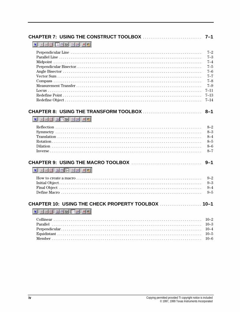
CHAPTER 7: USING THE CONSTRUCT TOOLBOX ............................... 7–1
Perpendicular Line ..................................................................... 7–2Parallel Line ........................................................................... 7–3Midpoint .............................................................................. 7–4Perpendicular Bisector.................................................................. 7–5Angle Bisector ......................................................................... 7–6Vector Sum ............................................................................ 7–7Compass .............................................................................. 7–8Measurement Transfer .................................................................. 7–9Locus ................................................................................. 7–11Redefine Point ......................................................................... 7–13Redefine Object ........................................................................ 7–14
CHAPTER 8: USING THE TRANSFORM TOOLBOX ............................... 8–1
Reflection ............................................................................. 8–2Symmetry ............................................................................. 8–3Translation ............................................................................ 8–4Rotation............................................................................... 8–5Dilation ............................................................................... 8–6Inverse................................................................................ 8–7
CHAPTER 9: USING THE MACRO TOOLBOX ..................................... 9–1
How to create a macro.................................................................. 9–2Initial Object........................................................................... 9–3Final Object ........................................................................... 9–4Define Macro .......................................................................... 9–5
CHAPTER 10: USING THE CHECK PROPERTY TOOLBOX ...................... 10–1
Collinear .............................................................................. 10–2Parallel ............................................................................... 10–3Perpendicular.......................................................................... 10–4Equidistant ............................................................................ 10–5Member ............................................................................... 10–6
vCopying permitted provided TI copyright notice is included© 1997, 1999 Texas Instruments Incorporated
Table of Contents (continued)
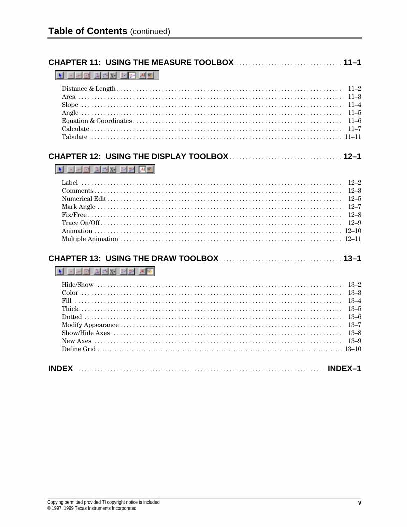
CHAPTER 11: USING THE MEASURE TOOLBOX ................................. 11–1
Distance & Length...................................................................... 11–2Area .................................................................................. 11–3Slope ................................................................................. 11–4Angle ................................................................................. 11–5Equation & Coordinates................................................................. 11–6Calculate .............................................................................. 11–7Tabulate .............................................................................. 11–11
CHAPTER 12: USING THE DISPLAY TOOLBOX ................................... 12–1
Label ................................................................................. 12–2Comments............................................................................. 12–3Numerical Edit......................................................................... 12–5Mark Angle ............................................................................ 12–7Fix/Free............................................................................... 12–8Trace On/Off........................................................................... 12–9Animation ............................................................................. 12–10Multiple Animation ..................................................................... 12–11
CHAPTER 13: USING THE DRAW TOOLBOX ...................................... 13–1
Hide/Show ............................................................................ 13–2Color ................................................................................. 13–3Fill ................................................................................... 13–4Thick ................................................................................. 13–5Dotted ................................................................................ 13–6Modify Appearance..................................................................... 13–7Show/Hide Axes ....................................................................... 13–8New Axes ............................................................................. 13–9Define Grid ..................................................................................................... 13–10
INDEX ............................................................................. INDEX–1
vi Copying permitted provided TI copyright notice is included© 1997, 1999 Texas Instruments Incorporated
About this Guidebook
The Cabri Geometry II Guidebook contains user information about the Cabri Geometry IIsoftware. It provides descriptions, procedures, illustrations, and examples for using the softwarefeatures on Macintosh computers, and Windowsé and MS-DOSë-based PCs.
4 Many of the procedures, illustrations, and examples are virtually the same for the differentcomputer types. Significant differences between the Macintosh, Windows, and DOS versionsare identified for your convenience.
4 Most of the illustrations are from the Macintosh version; several are from the Windows andDOS versions. Due to space limitations, we could not show every illustration for each version.Therefore, some illustrations in this guidebook may be slightly different on your computer.
4 Key names are shown in small capital letters such as CTRL for the Control key and ESC for theEscape key. The RETURN key on the Macintosh and the ENTER key on the PC keyboard performthe same function. In this guidebook, “Press ENTER” means to press either ENTER or RETURN.
Structure
The Cabri Geometry II Guidebook contains the following chapters and appendices:
4 Chapter 1 describes the basic operations for using Cabri II, starting with checking systemrequirements for installing the software, through constructing objects, to saving and printing aconstruction file.
4 Chapter 2 describes the Cabri II menus and provides step-by-step procedures for using them.
4 Chapters 3 through 13 describe the Cabri II tools and provide step-by-step procedures forusing them. Each chapter discusses a specific group of Cabri II tools.
Definitions
The following definitions will help you in your understanding of this guidebook.
point When used as an instruction, point means to place the screen pointer ontop of the object you wish to select.
click Click means to press and release the mouse button quickly, usually whenpointing to a specific location
double-click Double-click means to click the mouse button twice in succession.
drag Drag means to point to the object you want to drag, press and hold themouse button to select the object, and move the screen pointer to a newlocation. Release the mouse button to stop dragging.
modify When used as an instruction, modify means to change the appearance,size, location, or orientation of the object.
marquee outline Marquee outline is the outline of an object in animated dots, similar to amovie marquee.
marquee rectangle Marquee rectangle is the selection rectangle that appears when you dragwith the Pointer tool from an unoccupied location in the drawing window.When you release the mouse button, objects that lie completely withinthe rectangle are selected.
Chapter 1: Learning the Basics 1-1Copying permitted provided TI copyright notice is included© 1997, 1999 Texas Instruments Incorporated
Chapter 1: Learning the Basics
This chapter provides descriptions and examples of basic operations in Cabri Geometry II.Becoming familiar with these items will enhance your usage. Differences between the Macintosh,Windows, and MS-DOS versions are explicitly described where applicable. For convenience, DOSwill be used in the remainder of this guidebook to mean MS-DOS.
The following topics are discussed:
FIRST STEPS CONSTRUCTING OBJECTS
Checking system requirements
Installing Cabri Geometry II
Starting Cabri Geometry II
Optimizing your Macintosh systemconfiguration
Changing your Macintosh systemconfiguration using Cabri Geometry II
Using Cabri Geometry II on a network
The Cabri Geometry II window
Accessing on-line help
About menus and toolboxes
Pointers that guide you
Creating and selecting points
Handling ambiguities
Determining dependent and independentobjects
Dragging
Using the Undo/Redo command
Deleting objects
Changing the appearance of objects
Labeling objects
Scrolling the drawing window
Saving and printing
1-2 Chapter 1: Learning the Basics Copying permitted provided TI copyright notice is included© 1997, 1999 Texas Instruments Incorporated
First Steps
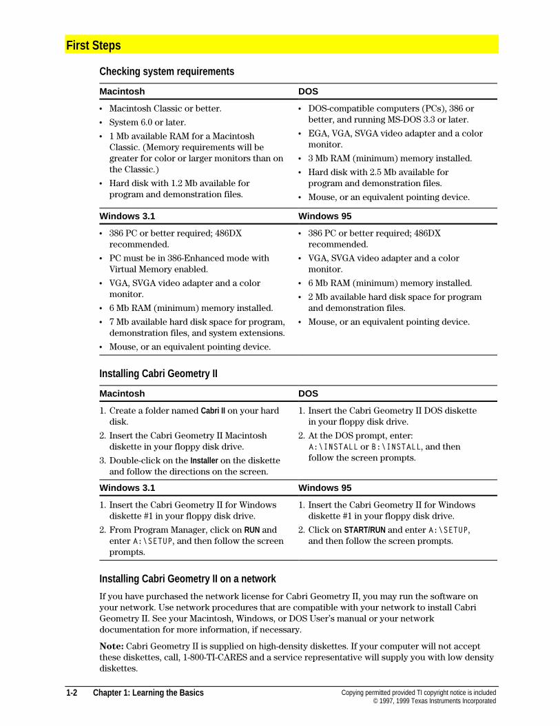
Checking system requirements
Macintosh DOS
¦ Macintosh Classic or better.
¦ System 6.0 or later.
¦ 1 Mb available RAM for a MacintoshClassic. (Memory requirements will begreater for color or larger monitors than onthe Classic.)
¦ Hard disk with 1.2 Mb available forprogram and demonstration files.
¦ DOS-compatible computers (PCs), 386 orbetter, and running MS-DOS 3.3 or later.
¦ EGA, VGA, SVGA video adapter and a colormonitor.
¦ 3 Mb RAM (minimum) memory installed.
¦ Hard disk with 2.5 Mb available forprogram and demonstration files.
¦ Mouse, or an equivalent pointing device.
Windows 3.1 Windows 95
¦ 386 PC or better required; 486DXrecommended.
¦ PC must be in 386-Enhanced mode withVirtual Memory enabled.
¦ VGA, SVGA video adapter and a colormonitor.
¦ 6 Mb RAM (minimum) memory installed.
¦ 7 Mb available hard disk space for program,demonstration files, and system extensions.
¦ Mouse, or an equivalent pointing device.
¦ 386 PC or better required; 486DXrecommended.
¦ VGA, SVGA video adapter and a colormonitor.
¦ 6 Mb RAM (minimum) memory installed.
¦ 2 Mb available hard disk space for programand demonstration files.
¦ Mouse, or an equivalent pointing device.
Installing Cabri Geometry II
Macintosh DOS
1. Create a folder named Cabri II on your harddisk.
2. Insert the Cabri Geometry II Macintoshdiskette in your floppy disk drive.
3. Double-click on the Installer on the disketteand follow the directions on the screen.
1. Insert the Cabri Geometry II DOS diskettein your floppy disk drive.
2. At the DOS prompt, enter:A:\INSTALL or B:\INSTALL, and thenfollow the screen prompts.
Windows 3.1 Windows 95
1. Insert the Cabri Geometry II for Windowsdiskette #1 in your floppy disk drive.
2. From Program Manager, click on RUN andenter A:\SETUP, and then follow the screenprompts.
1. Insert the Cabri Geometry II for Windowsdiskette #1 in your floppy disk drive.
2. Click on START/RUN and enter A:\SETUP,and then follow the screen prompts.
Installing Cabri Geometry II on a network
If you have purchased the network license for Cabri Geometry II, you may run the software onyour network. Use network procedures that are compatible with your network to install CabriGeometry II. See your Macintosh, Windows, or DOS User’s manual or your networkdocumentation for more information, if necessary.
Note: Cabri Geometry II is supplied on high-density diskettes. If your computer will not acceptthese diskettes, call, 1-800-TI-CARES and a service representative will supply you with low densitydiskettes.
Chapter 1: Learning the Basics 1-3Copying permitted provided TI copyright notice is included© 1997, 1999 Texas Instruments Incorporated
Installing Cabri Geometry II on a network (continued)
Macintosh and DOS
1. Install Cabri Geometry II on the network server using the instructions given on the previouspage.
2. Run the program from the server the first time, and enter the requested information.
3. To run Cabri Geometry II on each network client, go to the directory on the network serverwhere the Cabri Geometry II application is installed. Macintosh users may double-click onthe Cabri II icon; DOS users may run Cabri2.exe to start the program.
The procedure described below, for Windows users, allows multiple client computers to run CabriGeometry II using the application software installed on the network server. Each client computeris provided with the necessary system files to run Cabri Geometry II and a shortcut icon that islinked to the application file on the network server.
Windows 3.1 and Windows 95
1. Install Cabri Geometry II on the network server using the instructions given on the previouspage. In the Select Destination screen, you must select a directory that will be accessible from eachclient computer on the network.
2. Temporarily copy setup.exe and setup.w02 from the installation diskettes to the same directory inwhich you installed Cabri Geometry II in step 1.
3. On each network client, go to the directory on the network server that contains setup.exe anddouble-click to on this file to run the setup program.
4. In the Select Destination Directory screen, click on the Browse button and select the same directorythat you used in step 1. Make sure the correct directory is displayed at the top of the window.You may edit the path, if necessary, and then click on OK. Ignore the message that the directoryalready exists.
5. In the Select Components screen, deselect the first three components. The installation programwill determine if the fourth component is necessary for Windows 3.1x users.
6. When Cabri Geometry II has been installed on all client computers, delete the two files thatwere temporarily copied to the network server in step 2.
Starting Cabri Geometry II
Macintosh DOS
You can use one of four methods to start thesoftware on a Macintosh:
¦ Use Open in the Finder .
¦ Double-click on the Cabri II icon.
¦ Double-click on any Cabri Geometry IIconstruction file, tool configuration file, ormacro file.
¦ Drag and drop any construction file ontothe Cabri II icon (System 7 users only).
Type CABRI and press ENTER from the DOSprompt directory where the Cabri Geometry IIfiles are located.
(Optional) Add the Cabri directory to your DOSpath to open Cabri Geometry II from anydirectory.
Windows
Double-click on the Cabri II icon.
1-4 Chapter 1: Learning the Basics Copying permitted provided TI copyright notice is included© 1997, 1999 Texas Instruments Incorporated
First Steps (Continued)
Optimizing your Macintosh system configuration
If you are starting Cabri Geometry II on a Macintosh for the first time, you may need to make someadjustments to make Cabri Geometry II compatible with your Macintosh computer systemconfiguration.
Graphics intensive programs require a large amount of memory to operate. The amount of memoryrequired directly relates to the size of your monitor and to the number of colors chosen torepresent graphical elements. Cabri Geometry II may require more memory than other applicationsdue to its interactive nature. Cabri Geometry II can assist you in optimizing your system.
If you see a warning message from the Finder , you need to make some adjustments to your systemconfiguration. This message indicates the amount of memory needed to run Cabri Geometry IIefficiently on your computer with your current configuration.
Click the OK button to proceed (Cabri Geometry II does not start). Then close any applications orwindows that are currently open. This frees the memory that these applications are using.
To change the amount of memory allocated to Cabri Geometry II, first make sure the Cabri II icon isselected. Then, from the Finder , select Get Info in the File menu. Once the Get Info window appears,decrease the application memory size to a value that is compatible with your computer.
If you are using System 7, an optional method is to use Virtual Memory to increase the amount ofmemory available to applications. See your Macintosh User’s manual for more information.
The previous dialog box indicates the amount of available memory on your computer. You mayalso select About this Macintosh in the Apple menu for the same information.
Changing your Macintosh system configuration using Cabri II
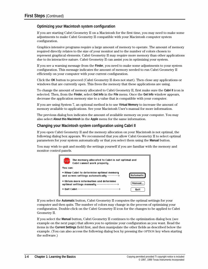
If you open Cabri Geometry II and the memory allocation on your Macintosh is not optimal, thefollowing dialog box appears. We recommend that you allow Cabri Geometry II to select optimalparameters for your system automatically or that you select them using the Manual button.
You may wish to quit and modify the settings yourself if you are familiar with the memory andmonitor control panels.
If you select the Automatic button, Cabri Geometry II computes the optimal settings for yourcomputer and then quits. The number of colors may change in the process of optimizing yourconfiguration. Double-click on the Cabri Geometry II icon for the changes to be applied to CabriGeometry II.
If you select the Manual button, Cabri Geometry II continues to the optimization dialog box (seeexample on the next page) that allows you to optimize your configuration as you want. Read theitems in the Current Settings field first, and then manipulate the other fields as described below theexample. (You can also access the following dialog box by pressing the OPTION key when startingthe software.)
Chapter 1: Learning the Basics 1-5Copying permitted provided TI copyright notice is included© 1997, 1999 Texas Instruments Incorporated
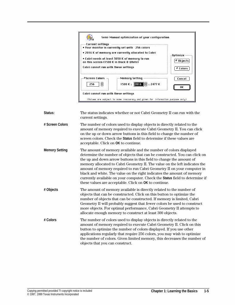
Status: The status indicates whether or not Cabri Geometry II can run with thecurrent settings.
# Screen Colors The number of colors used to display objects is directly related to theamount of memory required to execute Cabri Geometry II. You can clickon the up or down arrow buttons in this field to change the number ofscreen colors. Check the Status field to determine if these values areacceptable. Click on OK to continue.
Memory Setting The amount of memory available and the number of colors displayeddetermine the number of objects that can be constructed. You can click onthe up and down arrow buttons in this field to change the amount ofmemory allocated to Cabri Geometry II. The value on the left indicates theamount of memory required to run Cabri Geometry II on your computer inblack and white. The value on the right indicates the amount of memorycurrently available on your computer. Check the Status field to determine ifthese values are acceptable. Click on OK to continue.
# Objects The amount of memory available is directly related to the number ofobjects that can be constructed. Click on this button to optimize thenumber of objects that can be constructed. If memory is limited, CabriGeometry II will probably suggest that fewer colors be used to constructmore objects. For optimal performance, Cabri Geometry II attempts toallocate enough memory to construct at least 300 objects.
# Colors The number of colors used to display objects is directly related to theamount of memory required to execute Cabri Geometry II. Click on thisbutton to optimize the number of colors displayed. If you use otherapplications regularly that require 256 colors, you may wish to optimizethe number of colors. Given limited memory, this decreases the number ofobjects that you can construct.
1-6 Chapter 1: Learning the Basics Copying permitted provided TI copyright notice is included© 1997, 1999 Texas Instruments Incorporated
First Steps (Continued)
The Cabri Geometry II window
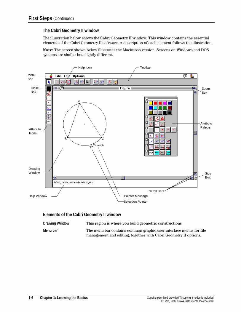
The illustration below shows the Cabri Geometry II window. This window contains the essentialelements of the Cabri Geometry II software. A description of each element follows the illustration.
Note: The screen shown below illustrates the Macintosh version. Screens on Windows and DOSsystems are similar but slightly different.
Elements of the Cabri Geometry II window
Drawing Window This region is where you build geometric constructions.
Menu bar The menu bar contains common graphic user interface menus for filemanagement and editing, together with Cabri Geometry II options.
AttributeIcons
MenuBar
Toolbar
Help Window
DrawingWindow
Help Icon
Selection Pointer
Scroll Bars
SizeBox
ZoomBox
Pointer Message
AttributePalette
CloseBox
This circle
Chapter 1: Learning the Basics 1-7Copying permitted provided TI copyright notice is included© 1997, 1999 Texas Instruments Incorporated
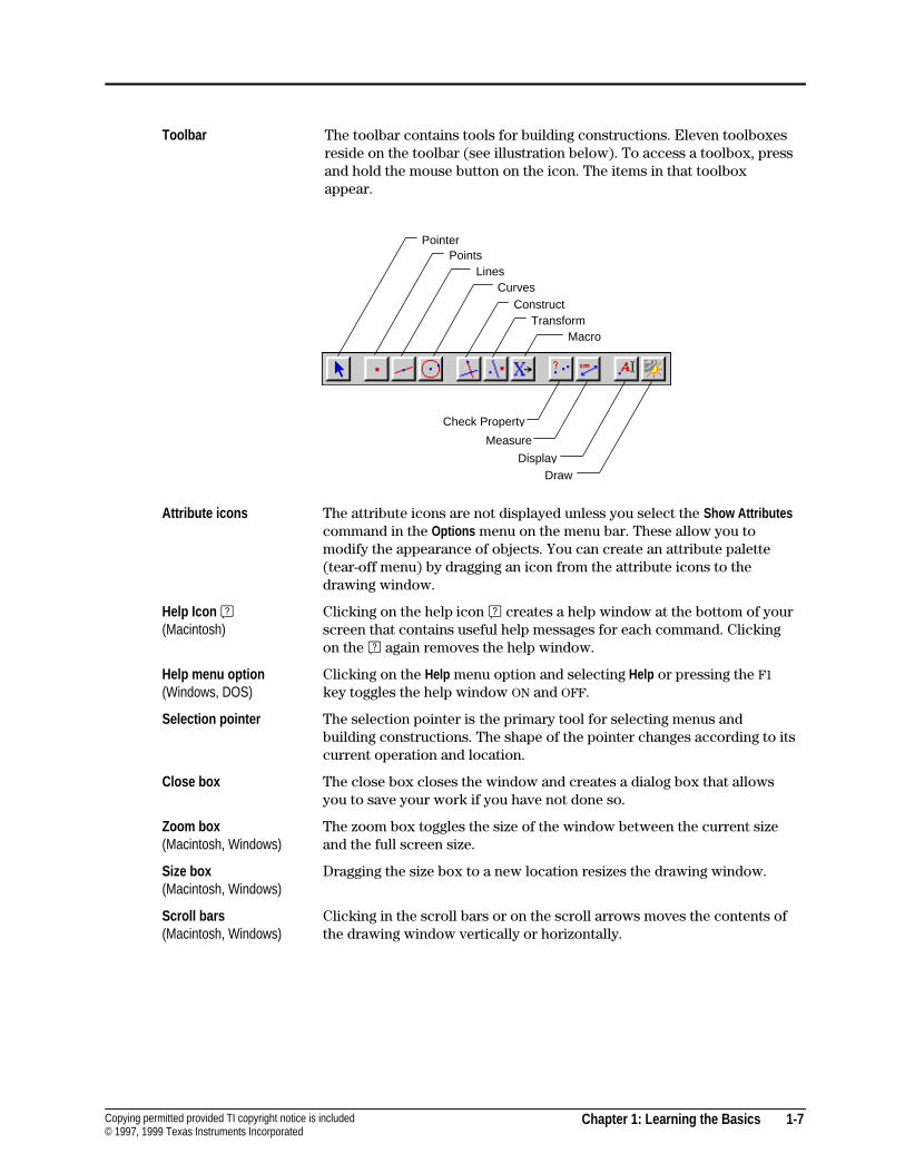
Toolbar The toolbar contains tools for building constructions. Eleven toolboxesreside on the toolbar (see illustration below). To access a toolbox, pressand hold the mouse button on the icon. The items in that toolboxappear.
Attribute icons The attribute icons are not displayed unless you select the Show Attributescommand in the Options menu on the menu bar. These allow you tomodify the appearance of objects. You can create an attribute palette(tear-off menu) by dragging an icon from the attribute icons to thedrawing window.
Help Icon A(Macintosh)
Clicking on the help icon A creates a help window at the bottom of yourscreen that contains useful help messages for each command. Clickingon the A again removes the help window.
Help menu option(Windows, DOS)
Clicking on the Help menu option and selecting Help or pressing the F1key toggles the help window ON and OFF.
Selection pointer The selection pointer is the primary tool for selecting menus andbuilding constructions. The shape of the pointer changes according to itscurrent operation and location.
Close box The close box closes the window and creates a dialog box that allowsyou to save your work if you have not done so.
Zoom box(Macintosh, Windows)
The zoom box toggles the size of the window between the current sizeand the full screen size.
Size box(Macintosh, Windows)
Dragging the size box to a new location resizes the drawing window.
Scroll bars(Macintosh, Windows)
Clicking in the scroll bars or on the scroll arrows moves the contents ofthe drawing window vertically or horizontally.
PointerPoints
LinesCurves
ConstructTransform
Macro
Check Property
Measure
DisplayDraw
1-8 Chapter 1: Learning the Basics Copying permitted provided TI copyright notice is included© 1997, 1999 Texas Instruments Incorporated
First Steps (Continued)
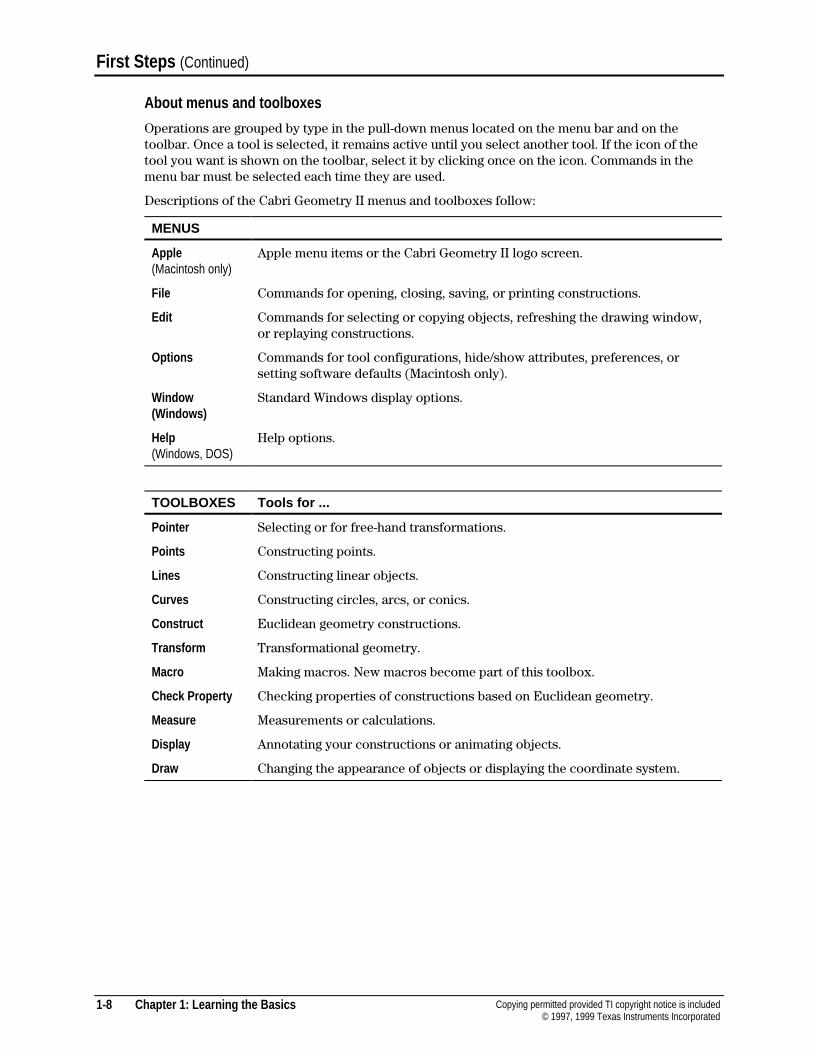
About menus and toolboxes
Operations are grouped by type in the pull-down menus located on the menu bar and on thetoolbar. Once a tool is selected, it remains active until you select another tool. If the icon of thetool you want is shown on the toolbar, select it by clicking once on the icon. Commands in themenu bar must be selected each time they are used.
Descriptions of the Cabri Geometry II menus and toolboxes follow:
MENUS
Apple(Macintosh only)
Apple menu items or the Cabri Geometry II logo screen.
File Commands for opening, closing, saving, or printing constructions.
Edit Commands for selecting or copying objects, refreshing the drawing window,or replaying constructions.
Options Commands for tool configurations, hide/show attributes, preferences, orsetting software defaults (Macintosh only).
Window(Windows)
Standard Windows display options.
Help(Windows, DOS)
Help options.
TOOLBOXES Tools for ...
Pointer Selecting or for free-hand transformations.
Points Constructing points.
Lines Constructing linear objects.
Curves Constructing circles, arcs, or conics.
Construct Euclidean geometry constructions.
Transform Transformational geometry.
Macro Making macros. New macros become part of this toolbox.
Check Property Checking properties of constructions based on Euclidean geometry.
Measure Measurements or calculations.
Display Annotating your constructions or animating objects.
Draw Changing the appearance of objects or displaying the coordinate system.
Chapter 1: Learning the Basics 1-9Copying permitted provided TI copyright notice is included© 1997, 1999 Texas Instruments Incorporated
Accessing on-line help
Macintosh DOS
¦ Access on-line help by clicking on the helpicon A in the menu bar of the CabriGeometry II drawing window.
¦ A window appears at the bottom of yourdrawing that contains information aboutthe tool currently selected.
¦ Select additional tools to see their helpinformation.
¦ Remove the help window by clicking onthe help icon again or by clicking on theclose box in the help window.
¦ The close box appears when you click inthe help window.
¦ Access on-line help by clicking on theHelp menu option in the menu bar of theCabri Geometry II drawing window andselecting Help , or press F1.
¦ A window appears at the bottom of yourdrawing that contains information aboutthe tool currently selected.
¦ Select additional tools to see their helpinformation.
¦ Remove the help window by clicking onthe help icon again or by pressing F1.
Windows
¦ Access on-line help by clicking on theHelp menu option in the menu bar of theCabri Geometry II drawing window andselecting Help .
¦ A window appears at the bottom of yourdrawing that contains information aboutthe tool currently selected.
¦ Select additional tools to see their helpinformation.
¦ Remove the help window by clicking onthe help icon again.
1-10 Chapter 1: Learning the Basics Copying permitted provided TI copyright notice is included© 1997, 1999 Texas Instruments Incorporated
Constructing Objects
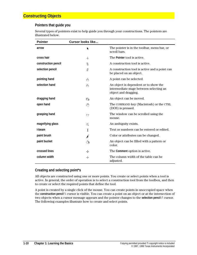
Pointers that guide you
Several types of pointers exist to help guide you through your constructions. The pointers areillustrated below.
Pointer Cursor looks like...
arrow " The pointer is in the toolbar, menu bar, orscroll bars.
cross hair ! The Pointer tool is active.
construction pencil # A construction tool is active.
selection pencil ' A construction tool is active and a point canbe placed on an object.
pointing hand $ A point can be selected.
selection hand & An object is dependent or to show theintermediate stage between selecting anobject and dragging.
dragging hand % An object can be moved.
open hand ( The COMMAND key (Macintosh) or the CTRL(DOS) is pressed.
grasping hand ) The window can be scrolled using themouse.
magnifying glass * An ambiguity exists.
I-beam I Text or numbers can be entered or edited.
paint brush 2 Color or attributes can be changed.
paint bucket 1 An object can be filled with a pattern orcolor.
crossed lines 4 The Comment option is active.
column width 3 The column width of the table can beadjusted.
Creating and selecting point*s
All objects are constructed using one or more points. You create or select points when a tool isactive. In general, the order of operation is to select a construction tool from the toolbox, and thento create or select the required points that define the tool.
A point is created by a single click of the mouse. You can create points in unoccupied space whenthe construction pencil # cursor is visible. You can create a point on an object or at the intersection oftwo objects when a cursor message appears and the pointer changes to the selection pencil ' cursor.The following examples illustrate how to create and select points.
Chapter 1: Learning the Basics 1-11Copying permitted provided TI copyright notice is included© 1997, 1999 Texas Instruments Incorporated
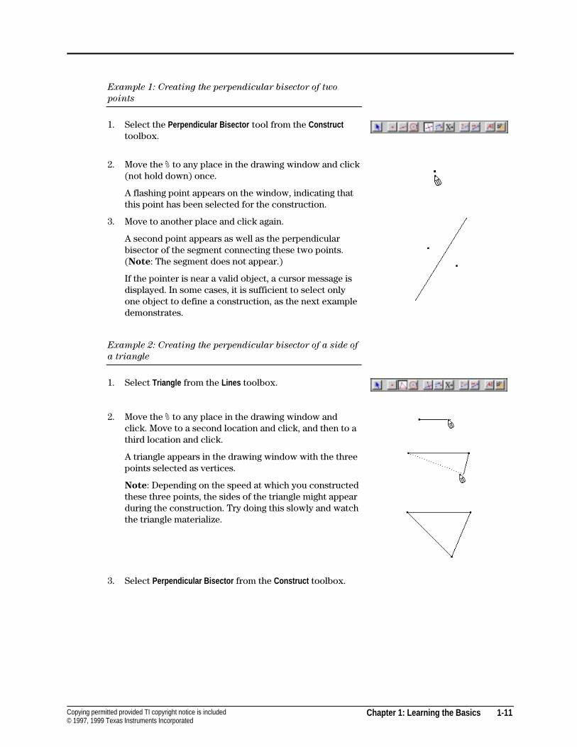
Example 1: Creating the perpendicular bisector of two
points
1. Select the Perpendicular Bisector tool from the Constructtoolbox.
2. Move the # to any place in the drawing window and click(not hold down) once.
A flashing point appears on the window, indicating thatthis point has been selected for the construction.
3. Move to another place and click again.
A second point appears as well as the perpendicularbisector of the segment connecting these two points.(Note: The segment does not appear.)
If the pointer is near a valid object, a cursor message isdisplayed. In some cases, it is sufficient to select onlyone object to define a construction, as the next exampledemonstrates.
Example 2: Creating the perpendicular bisector of a side of
a triangle
1. Select Triangle from the Lines toolbox.
2. Move the # to any place in the drawing window andclick. Move to a second location and click, and then to athird location and click.
A triangle appears in the drawing window with the threepoints selected as vertices.
Note: Depending on the speed at which you constructedthese three points, the sides of the triangle might appearduring the construction. Try doing this slowly and watchthe triangle materialize.
3. Select Perpendicular Bisector from the Construct toolbox.
1-12 Chapter 1: Learning the Basics Copying permitted provided TI copyright notice is included© 1997, 1999 Texas Instruments Incorporated
Constructing Objects (Continued)
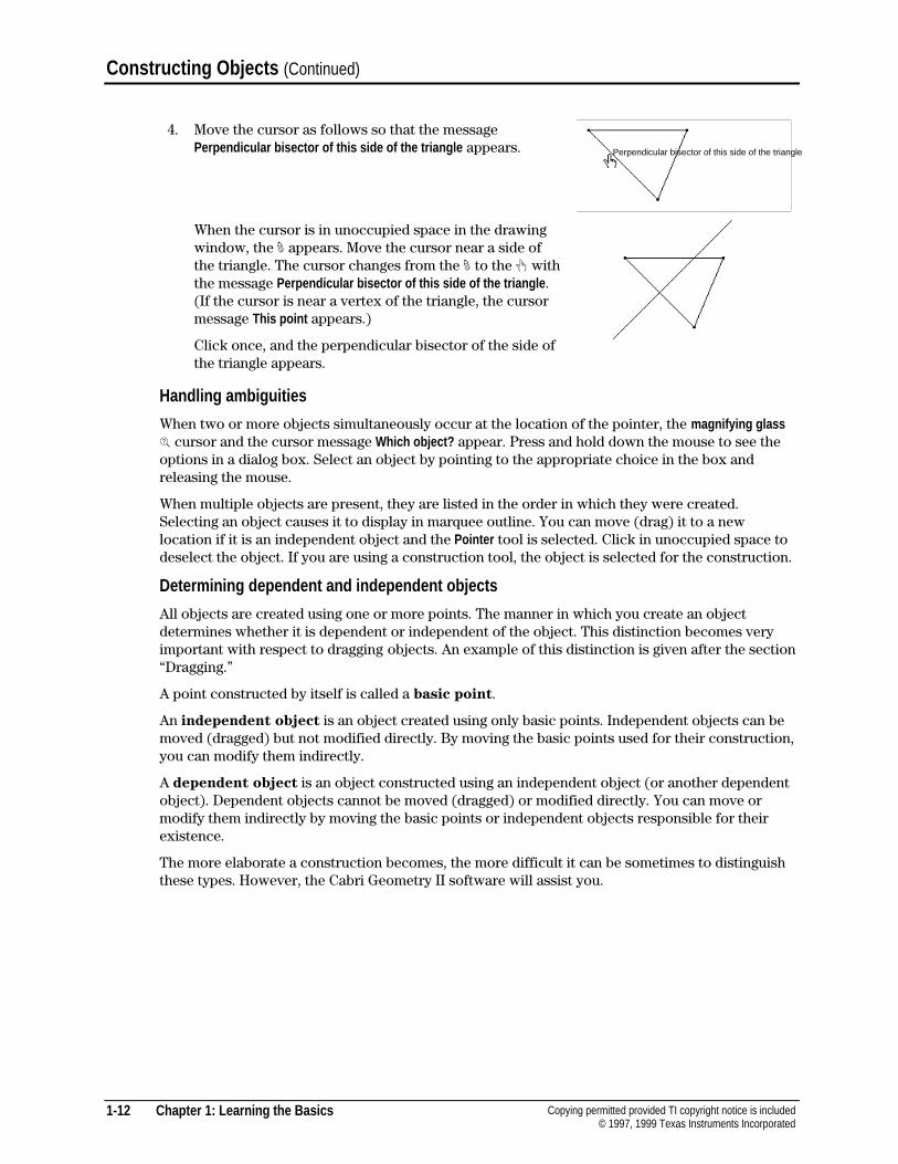
4. Move the cursor as follows so that the messagePerpendicular bisector of this side of the triangle appears.
When the cursor is in unoccupied space in the drawingwindow, the # appears. Move the cursor near a side ofthe triangle. The cursor changes from the # to the $ withthe message Perpendicular bisector of this side of the triangle .(If the cursor is near a vertex of the triangle, the cursormessage This point appears.)
Click once, and the perpendicular bisector of the side ofthe triangle appears.
Handling ambiguities
When two or more objects simultaneously occur at the location of the pointer, the magnifying glass* cursor and the cursor message Which object? appear. Press and hold down the mouse to see theoptions in a dialog box. Select an object by pointing to the appropriate choice in the box andreleasing the mouse.
When multiple objects are present, they are listed in the order in which they were created.Selecting an object causes it to display in marquee outline. You can move (drag) it to a newlocation if it is an independent object and the Pointer tool is selected. Click in unoccupied space todeselect the object. If you are using a construction tool, the object is selected for the construction.
Determining dependent and independent objects
All objects are created using one or more points. The manner in which you create an objectdetermines whether it is dependent or independent of the object. This distinction becomes veryimportant with respect to dragging objects. An example of this distinction is given after the section“Dragging.”
A point constructed by itself is called a basic point.
An independent object is an object created using only basic points. Independent objects can bemoved (dragged) but not modified directly. By moving the basic points used for their construction,you can modify them indirectly.
A dependent object is an object constructed using an independent object (or another dependentobject). Dependent objects cannot be moved (dragged) or modified directly. You can move ormodify them indirectly by moving the basic points or independent objects responsible for theirexistence.
The more elaborate a construction becomes, the more difficult it can be sometimes to distinguishthese types. However, the Cabri Geometry II software will assist you.
Perpendicular bisector of this side of the triangle
Chapter 1: Learning the Basics 1-13Copying permitted provided TI copyright notice is included© 1997, 1999 Texas Instruments Incorporated
Dragging
Dragging objects is valuable for generating conjectures. You can modify an object by dragging allor part of it to a new location. Whether or not an object can be changed depends directly on how itwas created.
You can drag (move) a basic point to a new location, modifying, in turn, any object constructedusing it. An independent object can be modified with one of the tools from the Pointer toolbox. Youcannot alter a dependent object directly by dragging, but you can change it by dragging the basicpoints used in its construction.
Whenever an object can be dragged, the pointer changes to the selection hand & momentarily andthen to the dragging hand % cursor. When the % is visible, the selected object follows the pointer asyou move it.
If your computer's performance is sluggish, you may need to move the pointer to the location youwant and wait for the computations to finish with the new characteristics. This is particularlyevident when there are many objects in the drawing window.
If the object is dependent (cannot be dragged), the pointer changes to the selection hand & and thenreverts to the cross hair ! cursor.
Example 3: Evaluating basic points, independent objects,
and dependent objects
1. Construct the perpendicular bisector of a side of atriangle (see Example 2).
(The vertices are basic points, the triangle is anindependent object, and the perpendicular bisector is adependent object.)
2. Basic points:
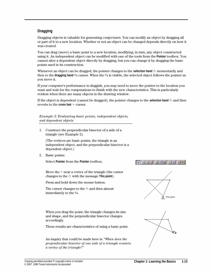
Select Pointer from the Pointer toolbox.
Move the ! near a vertex of the triangle (the cursorchanges to the $ with the message This point ).
Press and hold down the mouse button.
The cursor changes to the & and then almostimmediately to the %.
When you drag the point, the triangle changes its sizeand shape, and the perpendicular bisector changesaccordingly.
These results are characteristics of using a basic point.
An inquiry that could be made here is: “When does the
perpendicular bisector of one side of a triangle contain
a vertex of the triangle?”
This point
1-14 Chapter 1: Learning the Basics Copying permitted provided TI copyright notice is included© 1997, 1999 Texas Instruments Incorporated
Constructing Objects (Continued)
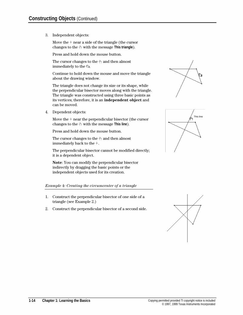
3. Independent objects:
Move the ! near a side of the triangle (the cursorchanges to the $ with the message This triangle ).
Press and hold down the mouse button.
The cursor changes to the & and then almostimmediately to the %.
Continue to hold down the mouse and move the triangleabout the drawing window.
The triangle does not change its size or its shape, whilethe perpendicular bisector moves along with the triangle.The triangle was constructed using three basic points asits vertices; therefore, it is an independent object andcan be moved.
4. Dependent objects:
Move the ! near the perpendicular bisector (the cursorchanges to the $ with the message This line ).
Press and hold down the mouse button.
The cursor changes to the & and then almostimmediately back to the !.
The perpendicular bisector cannot be modified directly;it is a dependent object.
Note: You can modify the perpendicular bisectorindirectly by dragging the basic points or theindependent objects used for its creation.
Example 4: Creating the circumcenter of a triangle
1. Construct the perpendicular bisector of one side of atriangle (see Example 2.)
2. Construct the perpendicular bisector of a second side.
This line
Chapter 1: Learning the Basics 1-15Copying permitted provided TI copyright notice is included© 1997, 1999 Texas Instruments Incorporated
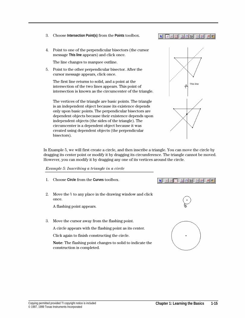
3. Choose Intersection Point(s) from the Points toolbox.
4. Point to one of the perpendicular bisectors (the cursormessage This line appears) and click once.
The line changes to marquee outline.
5. Point to the other perpendicular bisector. After thecursor message appears, click once.
The first line returns to solid, and a point at theintersection of the two lines appears. This point ofintersection is known as the circumcenter of the triangle.
The vertices of the triangle are basic points. The triangleis an independent object because its existence dependsonly upon basic points. The perpendicular bisectors aredependent objects because their existence depends uponindependent objects (the sides of the triangle). Thecircumcenter is a dependent object because it wascreated using dependent objects (the perpendicularbisectors).
In Example 5, we will first create a circle, and then inscribe a triangle. You can move the circle bydragging its center point or modify it by dragging its circumference. The triangle cannot be moved.However, you can modify it by dragging any one of its vertices around the circle.
Example 5: Inscribing a triangle in a circle
1. Choose Circle from the Curves toolbox.
2. Move the # to any place in the drawing window and clickonce.
A flashing point appears.
3. Move the cursor away from the flashing point.
A circle appears with the flashing point as its center.
Click again to finish constructing the circle.
Note: The flashing point changes to solid to indicate theconstruction is completed.
This line
1-16 Chapter 1: Learning the Basics Copying permitted provided TI copyright notice is included© 1997, 1999 Texas Instruments Incorporated
Constructing Objects (Continued)
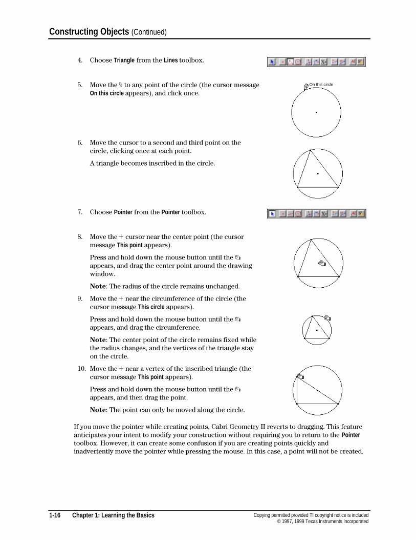
4. Choose Triangle from the Lines toolbox.
5. Move the # to any point of the circle (the cursor messageOn this circle appears), and click once.
6. Move the cursor to a second and third point on thecircle, clicking once at each point.
A triangle becomes inscribed in the circle.
7. Choose Pointer from the Pointer toolbox.
8. Move the ! cursor near the center point (the cursormessage This point appears).
Press and hold down the mouse button until the %appears, and drag the center point around the drawingwindow.
Note: The radius of the circle remains unchanged.
9. Move the ! near the circumference of the circle (thecursor message This circle appears).
Press and hold down the mouse button until the %appears, and drag the circumference.
Note: The center point of the circle remains fixed whilethe radius changes, and the vertices of the triangle stayon the circle.
10. Move the ! near a vertex of the inscribed triangle (thecursor message This point appears).
Press and hold down the mouse button until the %appears, and then drag the point.
Note: The point can only be moved along the circle.
If you move the pointer while creating points, Cabri Geometry II reverts to dragging. This featureanticipates your intent to modify your construction without requiring you to return to the Pointertoolbox. However, it can create some confusion if you are creating points quickly andinadvertently move the pointer while pressing the mouse. In this case, a point will not be created.
On this circle
Chapter 1: Learning the Basics 1-17Copying permitted provided TI copyright notice is included© 1997, 1999 Texas Instruments Incorporated
Using the Undo/Redo command
You can cancel an operation that has just been completed by using the Undo/Redo command in theEdit menu. Only the most recent operation can be undone.
To review additional steps in your construction, see the Replay Construction command in the Editmenu. This command allows you to replay each step of a construction.
Deleting objects
Delete objects by selecting them, and then pressing DELETE or selecting the Clear command in theEdit menu.
Select multiple objects by pressing the mouse in free space and dragging a marquee rectanglearound the objects to be deleted. Only objects that are fully enclosed by the marquee rectangle willbe deleted. All selected objects are displayed in marquee outline.
Select all objects in the drawing window by using the Select All command in the Edit menu. Thenpress DELETE or select Clear from the Edit menu. You can also clear the entire drawing window bypressing COMMAND+A (Macintosh) or CTRL+A (Windows, DOS) simultaneously, releasing, thenpressing DELETE.
WARNING! When an object is deleted, all objects that depend on that object are deleted as well. Itis possible to delete an entire construction by deleting a single point. If you accidentally delete anobject, you can recover it by using the Undo/Redo command in the Edit menu.
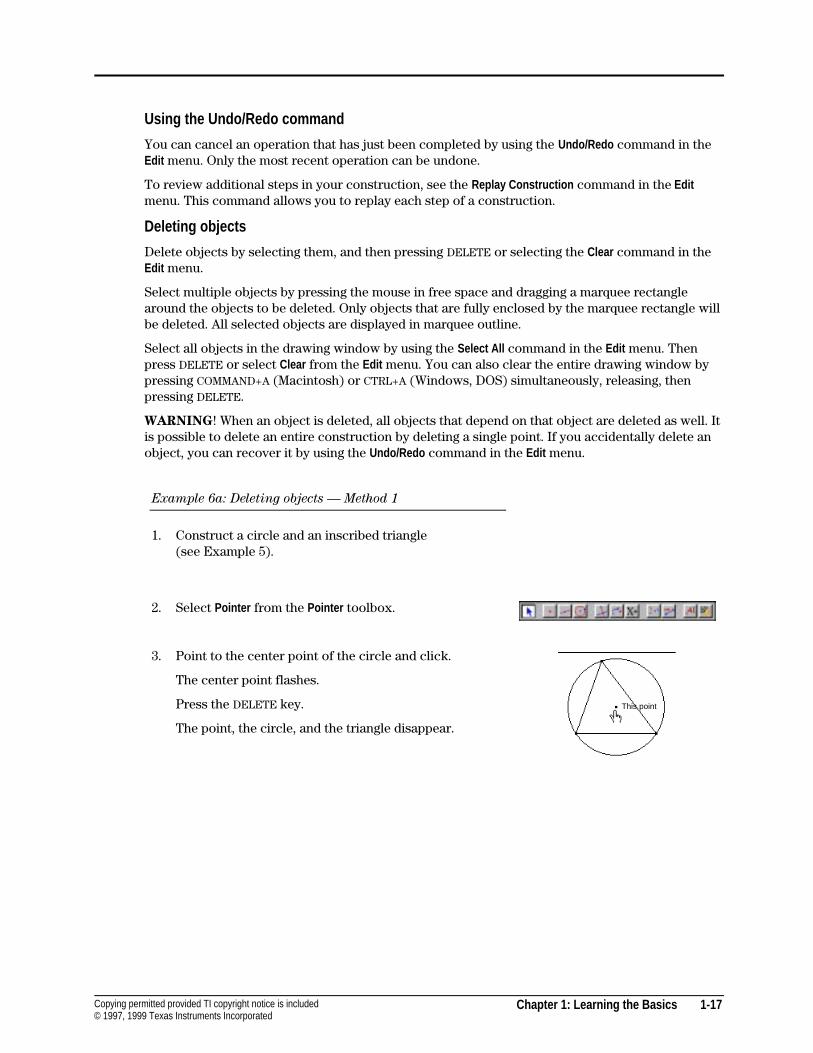
Example 6a: Deleting objects — Method 1
1. Construct a circle and an inscribed triangle(see Example 5).
2. Select Pointer from the Pointer toolbox.
3. Point to the center point of the circle and click.
The center point flashes.
Press the DELETE key.
The point, the circle, and the triangle disappear.
This point
1-18 Chapter 1: Learning the Basics Copying permitted provided TI copyright notice is included© 1997, 1999 Texas Instruments Incorporated
Constructing Objects (Continued)
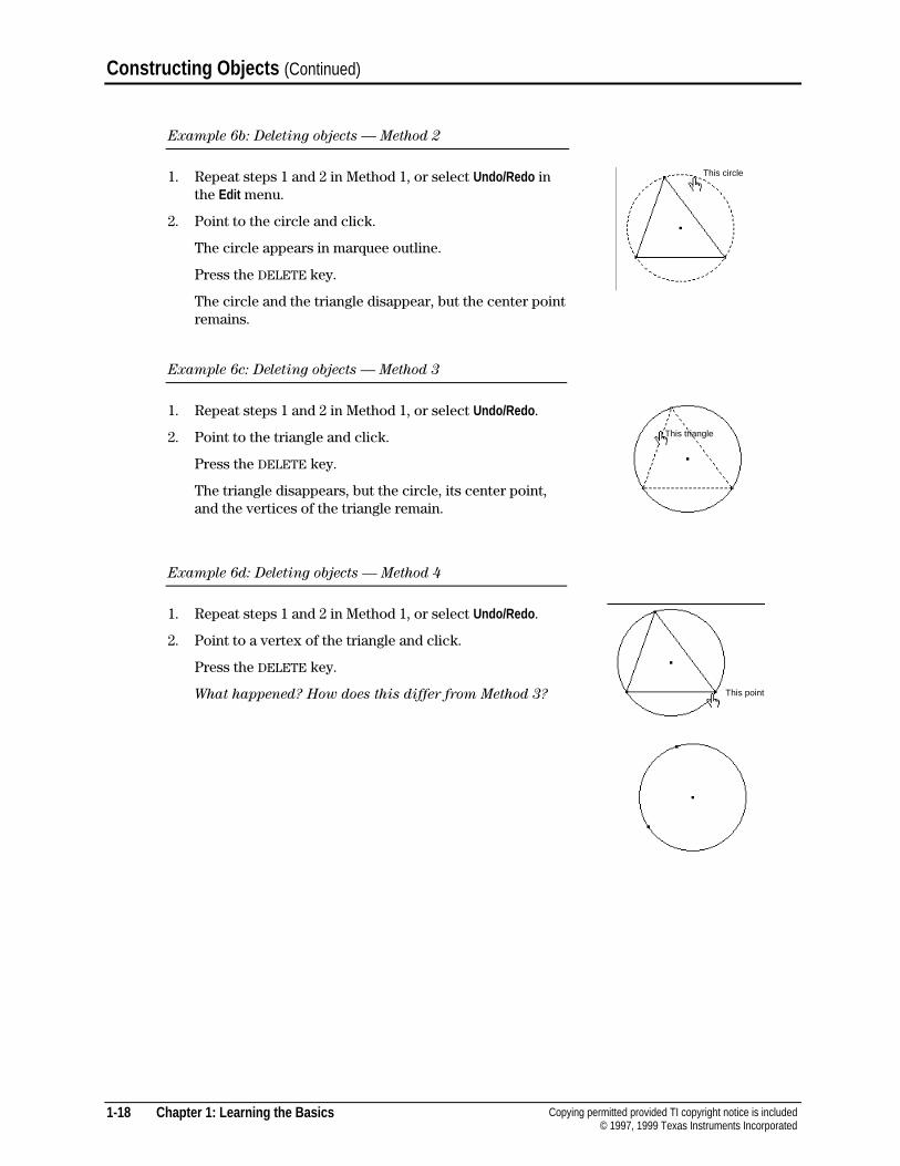
Example 6b: Deleting objects — Method 2
1. Repeat steps 1 and 2 in Method 1, or select Undo/Redo inthe Edit menu.
2. Point to the circle and click.
The circle appears in marquee outline.
Press the DELETE key.
The circle and the triangle disappear, but the center pointremains.
Example 6c: Deleting objects — Method 3
1. Repeat steps 1 and 2 in Method 1, or select Undo/Redo .
2. Point to the triangle and click.
Press the DELETE key.
The triangle disappears, but the circle, its center point,and the vertices of the triangle remain.
Example 6d: Deleting objects — Method 4
1. Repeat steps 1 and 2 in Method 1, or select Undo/Redo .
2. Point to a vertex of the triangle and click.
Press the DELETE key.
What happened? How does this differ from Method 3?
This circle
This triangle
This point
Chapter 1: Learning the Basics 1-19Copying permitted provided TI copyright notice is included© 1997, 1999 Texas Instruments Incorporated
Changing the Appearance of Objects
You can change the appearance of objects from the Attributes toolbar or the Draw toolbox.
Access the Attributes toolbar from the Hide/Show Attributes command in the Options menu. In the Drawtoolbox, use the Fill , Thick , Dotted , or Modify Appearance tools.
To apply attributes from tools in the Draw menu, select the tool, and then select the object to bemodified. To use an option from the Attributes toolbar, first select the objects to be modified, andthen select the attribute.
Labeling objects
You can label points in two ways — as you create them or with the Label tool in the Display toolbox.
Labeling objects as they are created is intended for quick access and is limited to fivealphanumeric characters. Editing is not available at this stage. However, after constructing theobject, you can edit the label with the Label tool.
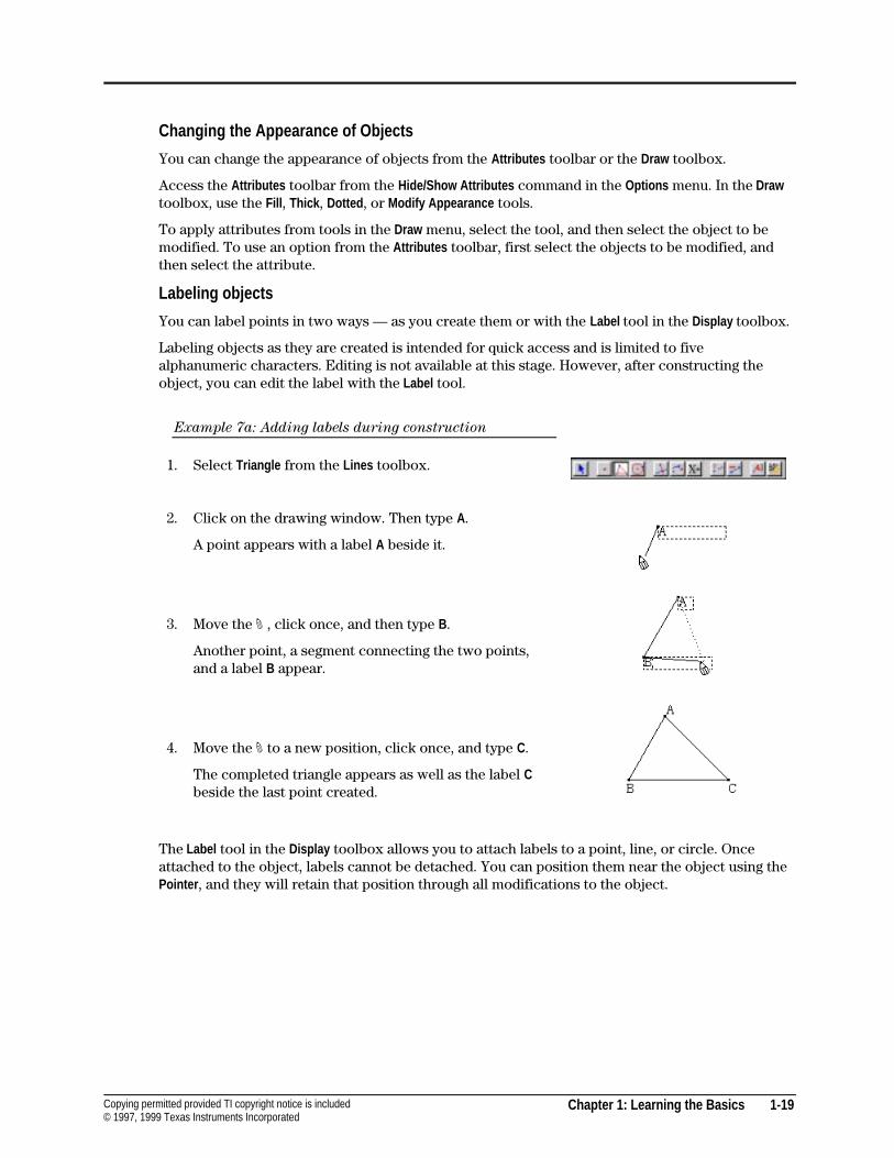
Example 7a: Adding labels during construction
1. Select Triangle from the Lines toolbox.
2. Click on the drawing window. Then type A.
A point appears with a label A beside it.
3. Move the # , click once, and then type B.
Another point, a segment connecting the two points,and a label B appear.
4. Move the # to a new position, click once, and type C.
The completed triangle appears as well as the label Cbeside the last point created.
The Label tool in the Display toolbox allows you to attach labels to a point, line, or circle. Onceattached to the object, labels cannot be detached. You can position them near the object using thePointer , and they will retain that position through all modifications to the object.
1-20 Chapter 1: Learning the Basics Copying permitted provided TI copyright notice is included© 1997, 1999 Texas Instruments Incorporated
Constructing Objects (Continued)
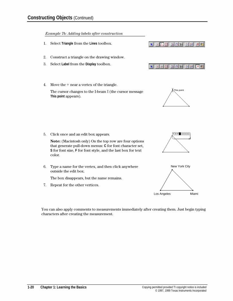
Example 7b: Adding labels after construction
1. Select Triangle from the Lines toolbox.
2. Construct a triangle on the drawing window.
3. Select Label from the Display toolbox.
4. Move the ! near a vertex of the triangle.
The cursor changes to the I-beam I (the cursor messageThis point appears).
5. Click once and an edit box appears.
Note: (Macintosh only) On the top row are four optionsthat generate pull-down menus: C for font character set,S for font size, F for font style, and the last box for textcolor.
6. Type a name for the vertex, and then click anywhereoutside the edit box.
The box disappears, but the name remains.
7. Repeat for the other vertices.
You can also apply comments to measurements immediately after creating them. Just begin typingcharacters after creating the measurement.
This point
New York City
Los Angeles Miami
Chapter 1: Learning the Basics 1-21Copying permitted provided TI copyright notice is included© 1997, 1999 Texas Instruments Incorporated
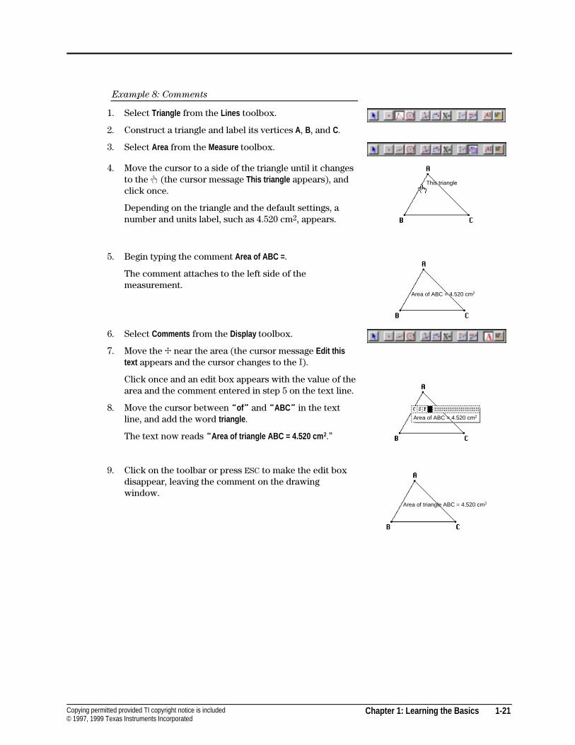
Example 8: Comments
1. Select Triangle from the Lines toolbox.
2. Construct a triangle and label its vertices A, B, and C.
3. Select Area from the Measure toolbox.
4. Move the cursor to a side of the triangle until it changesto the $ (the cursor message This triangle appears), andclick once.
Depending on the triangle and the default settings, anumber and units label, such as 4.520 cm2, appears.
5. Begin typing the comment Area of ABC = .
The comment attaches to the left side of themeasurement.
6. Select Comments from the Display toolbox.
7. Move the 4 near the area (the cursor message Edit thistext appears and the cursor changes to the I).
Click once and an edit box appears with the value of thearea and the comment entered in step 5 on the text line.
8. Move the cursor between “of” and “ABC” in the textline, and add the word triangle .
The text now reads “Area of triangle ABC = 4.520 cm 2.”
9. Click on the toolbar or press ESC to make the edit boxdisappear, leaving the comment on the drawingwindow.
This triangle
Area of ABC = 4.520 cm2
Area of ABC = 4.520 cm2
Area of triangle ABC = 4.520 cm2
1-22 Chapter 1: Learning the Basics Copying permitted provided TI copyright notice is included© 1997, 1999 Texas Instruments Incorporated
Constructing Objects (Continued)
Scrolling the drawing window
You can scroll the drawing window within a one-square-meter region by three methods:
4 Use the Show Drawing command in the File menu to view the entire one-square-meter regionin compressed form. You can reposition the active widow, which allows you to work inanother section of the drawing. (Note: When you click and hold the mouse button, thegrasping hand cursor ()) appears.)
4 Use the scroll bars on the right and bottom sides of the drawing window (Macintosh only).Clicking on the scroll bars or buttons moves the drawing in a horizontal or vertical direction.
4 Press the COMMAND key (Macintosh) or the CTRL key (Windows, DOS), then press down on theleft mouse button. The screen scrolls in the direction that you move the pointer.
Saving and printing
You can save a construction to a file at any time using the Save and Save as... commands in the Filemenu. If the construction has never been saved, these two commands have the same effect.
The Save dialog box allows you to name the construction and to choose the folder where it will bestored. If the construction has already been saved, the Save command is active only if the figurehas been modified since the previous save. The new version of the construction replaces the olderone.
The Save as... command allows you to save the figure to another folder or name without deletingthe older version.
You can print your Cabri Geometry II constructions on a printer. Printed constructions enhanceunderstanding by providing accurate, printed-to-scale manipulatives. The entire one-square-meterdrawing or a specified portion can be printed in both black and white, or color.
Chapter 2: Using the Menus 2-1Copying permitted provided TI copyright notice is included© 1997, 1999 Texas Instruments Incorporated
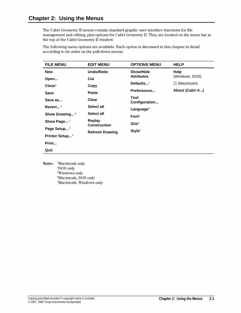
Chapter 2: Using the Menus
The Cabri Geometry II menus contain standard graphic user interface functions for filemanagement and editing, plus options for Cabri Geometry II. They are located on the menu bar atthe top of the Cabri Geometry II window.
The following menu options are available. Each option is discussed in this chapter in detailaccording to its order on the pull-down menus.
FILE MENU EDIT MENU OPTIONS MENU HELP
New
Open...
Close 1
Save
Save as...
Revert... 4
Show Drawing... 4
Show Page... 3
Page Setup... 5
Printer Setup... 2
Print...
Quit
Undo/Redo
Cut
Copy
Paste
Clear
Select all
Select all
ReplayConstruction
Refresh Drawing
Show/HideAttributes
Defaults... 1
Preferences...
ToolConfiguration...
Language 5
Font 5
Size5
Style 5
Help(Windows, DOS)
A (Macintosh)
About (Cabri II...)
Note: 1Macintosh only2DOS only3Windows only4Macintosh, DOS only5Macintosh, Windows only
2-2 Chapter 2: Using the Menus Copying permitted provided TI copyright notice is included© 1997, 1999 Texas Instruments Incorporated
File Menu
The File menu contains commands that relate to opening, closing, saving, printing, and viewingCabri Geometry II constructions.
A description of each item in the File menu as it relates to Cabri Geometry II is given below.Consult your Macintosh, Windows, or DOS User’s Guide for more information on the followingmenu items: New, Open , Close , Save, Save as , Page/Printer Setup , Print , and Quit .
New
Keyboard shortcut: COMMAND+N (Macintosh); CTRL+N (Windows, DOS)
The New command opens a new, blank Cabri Geometry II drawing window. For the Macintosh andWindows versions, the window appears on top of all other windows and is the active window. Thewindow is not assigned a name until you save it using Save or Save as . For the DOS version, onlyone drawing window at a time is displayed. Therefore, you are prompted to save your currentdrawing before the new drawing window takes effect.
Open...
Keyboard shortcut: COMMAND+O (Macintosh); CTRL+O (Windows, DOS)
The Open command generates a dialog box for opening an existing construction file, macro, toolconfiguration file, preference file, or TI-92 file. Use the dialog box to specify the folder and file toopen.
A construction file is displayed with the view that was visible when the file was last saved. You canview a summary of the steps used to create the construction interactively by selecting ReplayConstruction in the Edit menu.
A macro appears in the Macro toolbox and may be used immediately in the construction.
A tool configuration file immediately alters the Cabri Geometry II tool configuration as defined inthe file. See Tool Configuration in the Options menu for more information.
A preference file immediately alters Cabri Geometry II preferences as defined in the file. SeePreferences in the Options menu for more information.
Close
Keyboard shortcut: COMMAND+W. You also can click in the close box, located on the top left-handside of the active window in the title bar.
The Close command (Macintosh, Windows) closes the active drawing window. If changes weremade to the construction file, the Close dialog box appears and provides the option to save thechanges. If the file is new, the dialog changes to the Save dialog box. Cabri Geometry II is stillactive in your computer's memory after all files have been closed and does not free memory forapplications other than Cabri Geometry II.
Save
Keyboard shortcut: COMMAND+S (Macintosh); CTRL+S (Windows, DOS)
The Save command saves the construction in the active drawing window to the file name specifiedpreviously. The Save as dialog box appears if the file was not saved previously. The constructionremains open and active after saving.
The current view of a construction is saved with the file so that it opens to the same view whenreopened. Any macros used in the construction are automatically saved with the file and areavailable for use in future edit sessions with the saved file.
Chapter 2: Using the Menus 2-3Copying permitted provided TI copyright notice is included© 1997, 1999 Texas Instruments Incorporated
Save as...
The Save as ... command generates a dialog box for saving and naming the construction in the activedrawing window. The Save as dialog box provides the interface for saving a new file, saving a file toa new file name, file type, or location, or saving an existing file. Enter the information requested inthe dialog box to save the file.
For the Macintosh only, you can save the file as a text file if you wish to view its contents withanother program. For example, you can copy data in the Cabri Geometry II table to wordprocessing or spreadsheet files for further analysis using this method.
Revert...
The Revert... command returns the construction to its most recently saved version. This feature isuseful if you make modifications to your file that you later want to disregard. Revert is especiallyuseful when demonstrating a construction in the classroom.
Show Drawing... (Macintosh, DOS), Show Page... (Windows)
The size of the drawing window in which you build a geometric construction is one meter by onemeter. Show Drawing/Show Page lets you view this entire region. The entire figure, with the exceptionof text or measurement, is displayed in the following dialog box shown below.
A small window represents the portion of your construction that is visible on your computerscreen. The construction cannot be manipulated at this stage, but you can position the windowanywhere within the one-square-meter limits of the construction. Drag the window to move it toa new section of your construction. Click OK or Cancel to accept or cancel the operation.
4 For the Macintosh, the visible part of your construction can also be moved by clicking on thescroll bars or by dragging the drawing window while pressing the COMMAND key. Pressing theCOMMAND key changes the pointer to the open hand ( cursor; pressing the mouse button andthe COMMAND key changes the pointer to the grasping hand ) cursor. You can perform eithermethod without accessing the Show Drawing/Show Page command.
4 For the DOS versions, the visible part of your construction can also be moved by dragging thedrawing window with the grasping hand ) cursor. Moving the pointer to the drawing windowchanges the pointer to the open hand ( cursor; pressing the left mouse button changes thepointer to the grasping hand ) cursor. You can perform either method without accessing theShow Drawing/Show Page command.
4 For the Windows version, the visible part of your construction can be moved by also clickingon and then dragging the drawing window.
Page Setup... (Macintosh, Windows)
The Page Setup... command lets you specify the paper size and orientation (landscape or portrait),as well as other options that vary according to the printer.
Note: Cabri Geometry II prints figures to scale. That is, a triangle in your construction will beprinted exactly as specified, preserving the length of the sides and the measurement of the angles.If you change the Reduce or Enlarge option from 100%, the exact size of the figure will not bepreserved.
2-4 Chapter 2: Using the Menus Copying permitted provided TI copyright notice is included© 1997, 1999 Texas Instruments Incorporated
File Menu (Continued)
Print... (Macintosh, Windows)
The Print command for the Macintosh and Windows versions opens a dialog box that providesseveral options for printing your construction. After specifying the options you want in Page Setupand Print , click the Print button to send your construction to the printer.
The Placement options... (Macintosh only) lets you position your construction as it will appear on aprinted page by dragging the clear page in the screen. The drawing window (your computerscreen) is shown for a reference. Select Print labels in Italics to automatically print all labels in italicfont.
If your construction requires more than one page, select the Posterize option (Macintosh only) tonumber each page. You can select the position of the pages by using the pointer to drag the centerpage (outlined with bold lines) in the drawing region. You can change the number of pages bydragging the boxes in the upper-left and lower-right corners of the print region. This option makesit fun to create very large drawings, which can be taped together.
Printer Setup... (DOS)
The Printer Setup... command for the DOS version lets you select a printer and respective printquality, and to specify the page size (US Letter, US Legal, or A4 Letter) and orientation (portrait orlandscape). Click on the selections to see the menu options.
The Printer option lets you select one of the printers listed below. If your specific printer is not inthis list, select a printer that may be similar. (Note: The print quality setting that you select mayaffect the throughput of your printer. Allow ample time for high quality printer settings.)
¦ IBM/Epson 9 pin
¦ IBM/Epson 24 pin
¦ Epson Stylus Color
¦ DeskJet 500
¦ DeskJet 500C (CYM)
¦ DeskJet 500C (RGB)
¦ LaserJet HP
¦ Proprinter XL
Print... (DOS)
The size of the drawing window in which you build a geometric construction is one meter by onemeter. Print lets you view this entire region before printing your construction. The entire figure,with the exception of text or measurement, is displayed.
A small window represents the portion of your construction that will be printed. The constructioncannot be manipulated at this stage, but you can position the window anywhere within the one-square-meter limits of the construction. Drag the window to move it to a new section of yourconstruction. Click OK or Cancel to accept or cancel the operation. Clicking on OK sends the screenimage to your printer.
Quit
Keyboard shortcut: COMMAND+Q (Macintosh); CTRL+Q (Windows, DOS)
The Quit command closes all open files and quits Cabri Geometry II. It gives you the opportunity tosave changed or unsaved files.
Chapter 2: Using the Menus 2-5Copying permitted provided TI copyright notice is included© 1997, 1999 Texas Instruments Incorporated
Edit Menu
The Edit menu contains commands that relate to modifying the construction sequence, commandsfor exporting items in the drawing to the clipboard, and commands for selecting and deleting itemsin the drawing.
Undo/Redo
Keyboard shortcut: COMMAND+Z (Macintosh) or CTRL+Z (Windows, DOS)
The Undo/Redo command lets you undo the previous action or redo the undone action. Thesecommands have a recall of one action only. If you wish to review additional action steps, see ReplayConstruction on the next page.
The Windows version has an option in the Options/Preferences menu to let you disable the Undocommand. Disabling Undo provides for faster manipulation of very large and complex figures.
Cut/Copy/Paste
For the Macintosh and Windows versions, the Cut , Copy , and Paste commands use theMacintosh/Windows clipboard to import and export selected items to and from a construction. Forthe DOS version, these edit commands use a custom Cabri Geometry II clipboard.
Cut removes the selection from the construction and places it on the clipboard (Macintosh,Windows), or in the file $CLIPCAB.FIG (DOS).
Copy places the selected objects on the clipboard without removing them from the construction.Additionally, for the DOS version, the selection is saved to a file depending on the type of itemsthat are selected. Copying a construction creates two files $CLIPCAB.BMP and $CLIPCAB.FIG.Copying a table that contains data creates the file $CLIPCAB.TXT. Therefore, to copy and paste aconstruction or table into another application, such as a word processor or spreadsheet, whenusing the DOS version, select the objects and click on Copy . Then open the other application andinsert the appropriate .BMP, .FIG, or .TXT file to the desired location.
Paste copies the objects from the clipboard into the drawing window that is active. After pasting,the clipboard still contains the objects. Therefore, you can paste them in another location or Cabrifile, if you desire. In general, objects can be pasted as many times as available memory allows. Oneexception is copying the table. Because Cabri Geometry II defines only a single table and thecontents of a table are dependent upon other objects, Cabri Geometry II cannot duplicate the tablewithin the software. Further, only the contents of the table (the numerical values) are copied toanother application.
Objects are pasted in the same position in which they were copied. If you are pasting to the sameCabri Geometry II drawing from which you cut or copied the objects, they are pasted in the sameposition but with a small offset in location. The pasted objects are independent of the objects fromwhich they were cut or copied.
Keyboard shortcuts: COMMAND+X (Macintosh) or CTRL+X (Windows, DOS) for Cut , COMMAND+C(Macintosh) or CTRL+C (Windows, DOS) for Copy , and COMMAND+V (Macintosh) or CTRL+V(Windows, DOS) for Paste .
Clear
The Clear command removes selected objects from the construction. This command is equivalentto pressing the DELETE key. Objects are not placed on the clipboard.
2-6 Chapter 2: Using the Menus Copying permitted provided TI copyright notice is included© 1997, 1999 Texas Instruments Incorporated
Edit Menu (Continued)
Select all
Keyboard shortcut: COMMAND+A (Macintosh) or CTRL+A (DOS)
The Select al l command selects every object in a construction. Using Select all and then Clear is aneasy way to erase the contents of a construction to start again with a clean drawing.
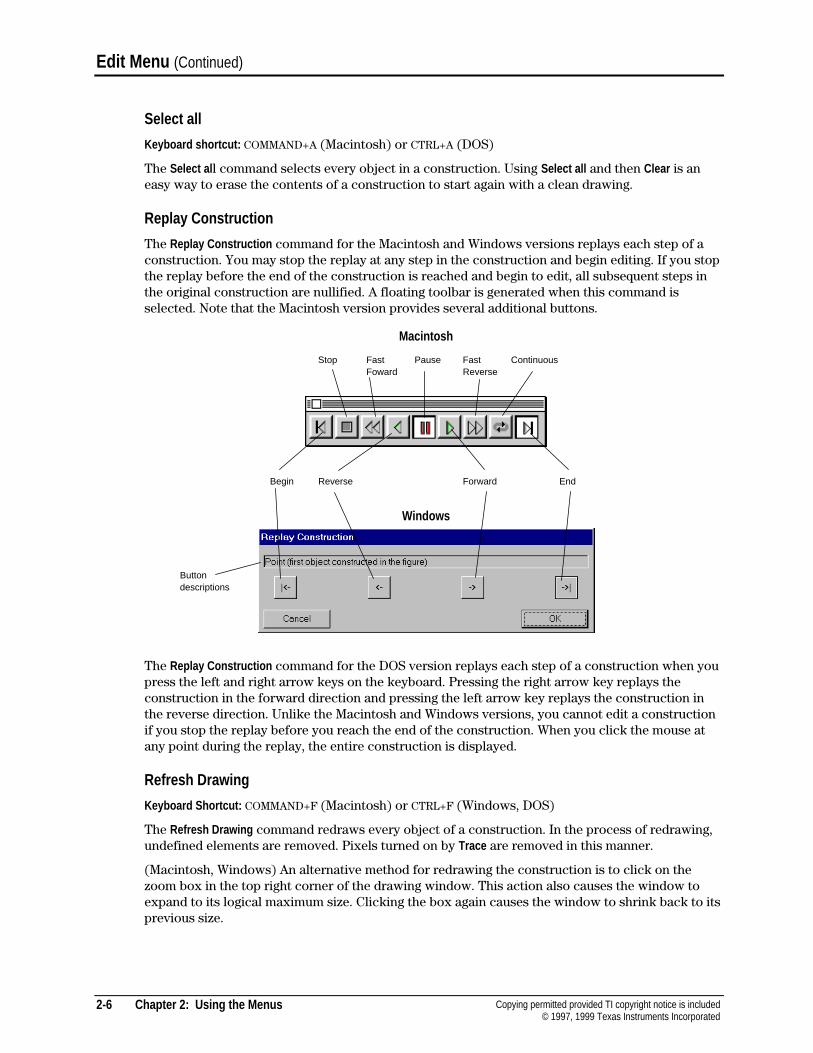
Replay Construction
The Replay Construction command for the Macintosh and Windows versions replays each step of aconstruction. You may stop the replay at any step in the construction and begin editing. If you stopthe replay before the end of the construction is reached and begin to edit, all subsequent steps inthe original construction are nullified. A floating toolbar is generated when this command isselected. Note that the Macintosh version provides several additional buttons.
Macintosh
Windows
The Replay Construction command for the DOS version replays each step of a construction when youpress the left and right arrow keys on the keyboard. Pressing the right arrow key replays theconstruction in the forward direction and pressing the left arrow key replays the construction inthe reverse direction. Unlike the Macintosh and Windows versions, you cannot edit a constructionif you stop the replay before you reach the end of the construction. When you click the mouse atany point during the replay, the entire construction is displayed.
Refresh Drawing
Keyboard Shortcut: COMMAND+F (Macintosh) or CTRL+F (Windows, DOS)
The Refresh Drawing command redraws every object of a construction. In the process of redrawing,undefined elements are removed. Pixels turned on by Trace are removed in this manner.
(Macintosh, Windows) An alternative method for redrawing the construction is to click on thezoom box in the top right corner of the drawing window. This action also causes the window toexpand to its logical maximum size. Clicking the box again causes the window to shrink back to itsprevious size.
Begin Reverse Forward End
Stop Fast Pause Fast ContinuousFoward Reverse
Buttondescriptions
Chapter 2: Using the Menus 2-7Copying permitted provided TI copyright notice is included© 1997, 1999 Texas Instruments Incorporated
Options Menu
The Options menu contains commands that relate to showing attributes of each construction tool,setting defaults, and defining the contents and configuration of the toolbar.
Hide/Show Attributes
The Hide/Show Attributes command hides and shows the attributes toolbar. You can toggle thecommand from one to the other.
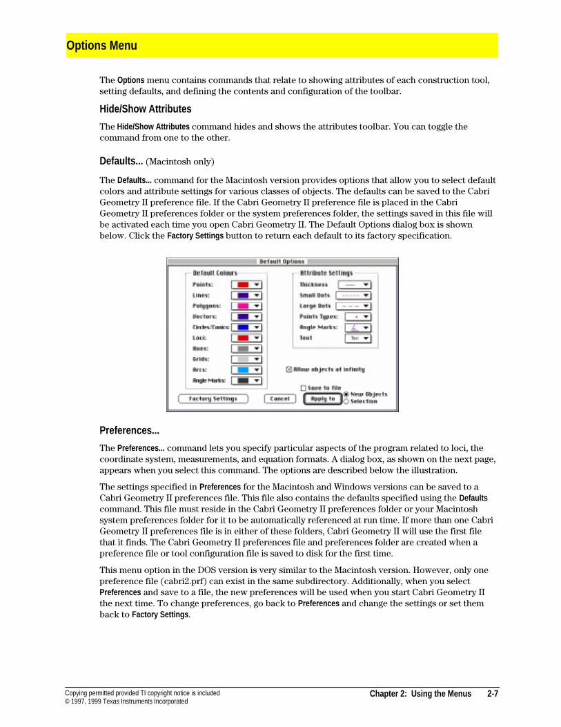
Defaults... (Macintosh only)
The Defaults... command for the Macintosh version provides options that allow you to select defaultcolors and attribute settings for various classes of objects. The defaults can be saved to the CabriGeometry II preference file. If the Cabri Geometry II preference file is placed in the CabriGeometry II preferences folder or the system preferences folder, the settings saved in this file willbe activated each time you open Cabri Geometry II. The Default Options dialog box is shownbelow. Click the Factory Settings button to return each default to its factory specification.
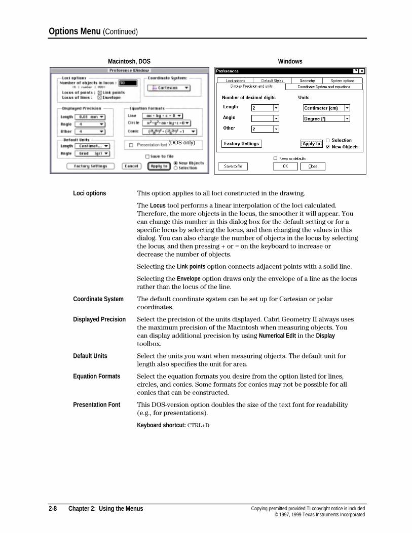
Preferences...
The Preferences... command lets you specify particular aspects of the program related to loci, thecoordinate system, measurements, and equation formats. A dialog box, as shown on the next page,appears when you select this command. The options are described below the illustration.
The settings specified in Preferences for the Macintosh and Windows versions can be saved to aCabri Geometry II preferences file. This file also contains the defaults specified using the Defaultscommand. This file must reside in the Cabri Geometry II preferences folder or your Macintoshsystem preferences folder for it to be automatically referenced at run time. If more than one CabriGeometry II preferences file is in either of these folders, Cabri Geometry II will use the first filethat it finds. The Cabri Geometry II preferences file and preferences folder are created when apreference file or tool configuration file is saved to disk for the first time.
This menu option in the DOS version is very similar to the Macintosh version. However, only onepreference file (cabri2.prf) can exist in the same subdirectory. Additionally, when you selectPreferences and save to a file, the new preferences will be used when you start Cabri Geometry IIthe next time. To change preferences, go back to Preferences and change the settings or set themback to Factory Settings .
2-8 Chapter 2: Using the Menus Copying permitted provided TI copyright notice is included© 1997, 1999 Texas Instruments Incorporated
Options Menu (Continued)
Macintosh, DOS Windows
Loci options This option applies to all loci constructed in the drawing.
The Locus tool performs a linear interpolation of the loci calculated.Therefore, the more objects in the locus, the smoother it will appear. Youcan change this number in this dialog box for the default setting or for aspecific locus by selecting the locus, and then changing the values in thisdialog. You can also change the number of objects in the locus by selectingthe locus, and then pressing + or − on the keyboard to increase ordecrease the number of objects.
Selecting the Link points option connects adjacent points with a solid line.
Selecting the Envelope option draws only the envelope of a line as the locusrather than the locus of the line.
Coordinate System The default coordinate system can be set up for Cartesian or polarcoordinates.
Displayed Precision Select the precision of the units displayed. Cabri Geometry II always usesthe maximum precision of the Macintosh when measuring objects. Youcan display additional precision by using Numerical Edit in the Displaytoolbox.
Default Units Select the units you want when measuring objects. The default unit forlength also specifies the unit for area.
Equation Formats Select the equation formats you desire from the option listed for lines,circles, and conics. Some formats for conics may not be possible for allconics that can be constructed.
Presentation Font This DOS-version option doubles the size of the text font for readability(e.g., for presentations).
Keyboard shortcut: CTRL+D
(DOS only)
Chapter 2: Using the Menus 2-9Copying permitted provided TI copyright notice is included© 1997, 1999 Texas Instruments Incorporated
Geometry This Windows-version option lets you select if points should be implicitlydefined, and if objects should be drawn to infinity.
Default Styles This Windows-version option lets you choose colors and font options forall toolbar commands.
System options This Windows-version option lets you set the following:
4 Bitmap Copy: œ Enhanced MetaFile format (EMF) for 32-bit versions ofWindows for high-quality, smooth lines. � Supports only bit-mappedformat (BMP), which is optional for Windows 95 and required forWindows 3.1x.
4 System Pallet: Defines the color palette to use when Cabri is in thebackground and the palette is changed by another application. œ Cabricolors will change when another option is brought to the foreground.� Cabri uses only colors present in the default system palette.
4 Disable Undo: œ Undo is enabled. � Undo is disabled, which provides forfaster manipulation of very large and complex figures.
4 Cursor Font: Lets you define the display font to use for displayindicators.
4 Menu Font: Lets you define the display font to use for menu options.
Tool Configuration...
The Tool Configuration... command allows teachers to configure Cabri Geometry II tools in thetoolbar to the aptitude of their class. You can rearrange or remove any tool in the toolbar. You canplace a tool configuration file in the preferences folder to automatically open Cabri Geometry IIwith the tool configuration specified in that file. The following steps show you how to customizeyour toolbar.
1. Select Tool Configuration in the Options menu.
2. To remove any tool from its current toolbox, select the tool.
The tool becomes attached to the pointer.
3. To relocate the attached tool to an existing toolbox, open any toolbox.
The relocated tool is inserted immediately below a tool that you highlighted with the cursor.The tool will be copied to the top of the toolbox if you do not highlight another tool.
4. To relocate the attached tool in a new toolbox, click in any empty section of the toolbar. Toremove the tool from the toolbar, click on the toolbar trash can.
5. To add spaces between a toolbox or tool, press the spacebar while pressing and holding themouse button down. You can add up to five spaces between toolboxes or tools.
To remove spaces between a toolbox or tool, press the BACKSPACE key while pressing andholding the mouse button down.
6. Add a password to prevent the tool configuration from being changed inadvertently.
7. Save your new tool configuration. If you save it to a tool configuration file, you can use thesame configuration in future sessions of Cabri Geometry II. Otherwise, the configuration isonly valid for the current session. If you want to return the tool configuration back to thefactory configuration, click on the Factory Settings button.
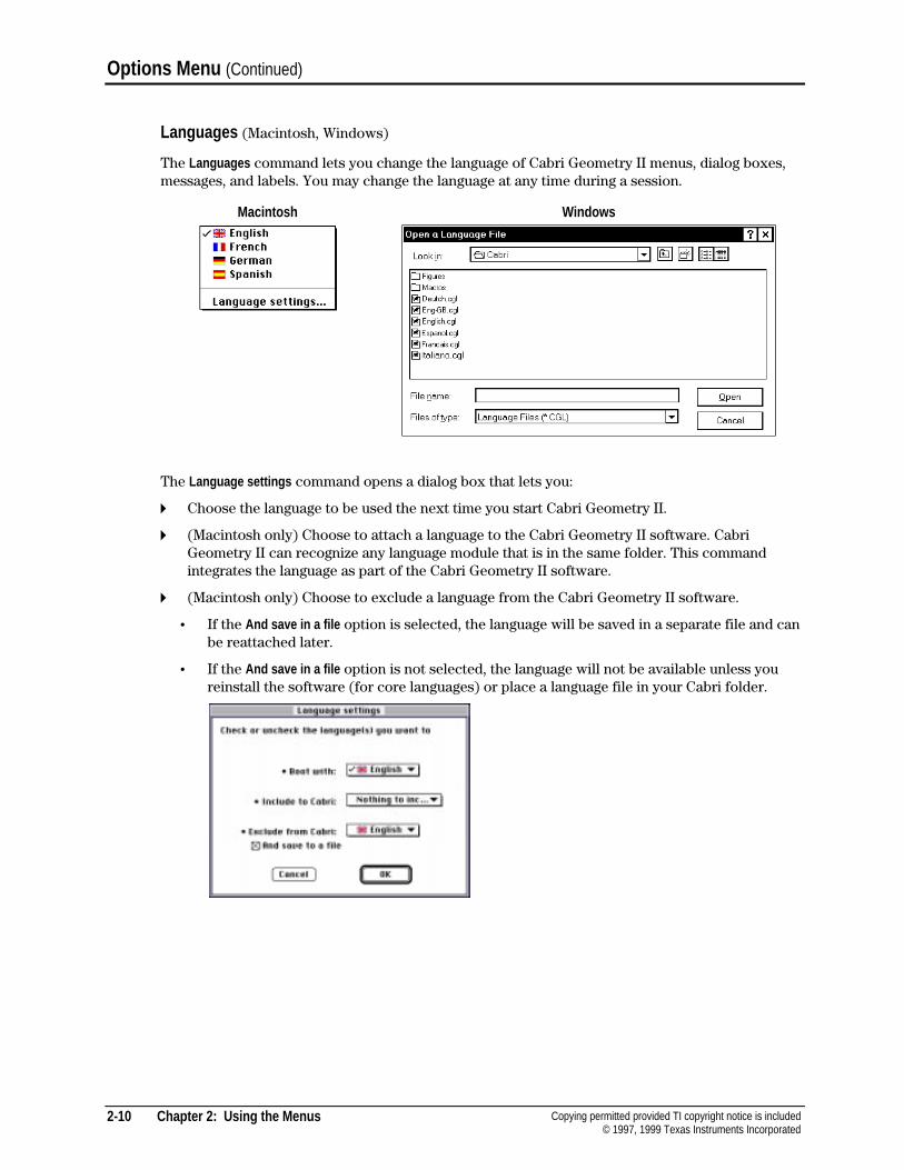
2-10 Chapter 2: Using the Menus Copying permitted provided TI copyright notice is included© 1997, 1999 Texas Instruments Incorporated
Options Menu (Continued)
Languages (Macintosh, Windows)
The Languages command lets you change the language of Cabri Geometry II menus, dialog boxes,messages, and labels. You may change the language at any time during a session.
Macintosh Windows
The Language settings command opens a dialog box that lets you:
4 Choose the language to be used the next time you start Cabri Geometry II.
4 (Macintosh only) Choose to attach a language to the Cabri Geometry II software. CabriGeometry II can recognize any language module that is in the same folder. This commandintegrates the language as part of the Cabri Geometry II software.
4 (Macintosh only) Choose to exclude a language from the Cabri Geometry II software.
¦ If the And save in a file option is selected, the language will be saved in a separate file and canbe reattached later.
¦ If the And save in a file option is not selected, the language will not be available unless youreinstall the software (for core languages) or place a language file in your Cabri folder.
Chapter 2: Using the Menus 2-11Copying permitted provided TI copyright notice is included© 1997, 1999 Texas Instruments Incorporated
Font (Macintosh, Windows)
The Font command in the Macintosh and Windows versions lets you view the fonts installed onyour computer. The √ symbol in the Macintosh version is shown next to the default font. Thedefault font applies to labels, comments, numerical values, and properties. You can specify fontsindependently for the Label , Comments , or Numerical Edit tools by first selecting the tool, and thenchanging the font in this menu. Point to another font to select it as the new default font.
Note: The Windows version dialog box lets you set the font size and style.
Size (Macintosh)
The Size command in the Macintosh version lets you view the font sizes available on yourcomputer. The point sizes in outlined text are sizes that your Macintosh should display withoutdistortion. The √ symbol is shown next to the default size. The default size applies to labels,comments, numerical values, and properties. You can specify size independently for the Label ,Comments , or Numerical Edit tools by first selecting the tool, and then changing the size in this menu.Point to another size to select it as the new size. For classroom demonstrations, it is useful to setthe default font size at 14 or 18 points.
Style (Macintosh)
The Style command in the Macintosh version lets you view the text styles available on yourcomputer. Text styles are independently applied to text and may be combined. For example, youcan specify bold-italic text by selecting each style type separately. The default style applies tolabels, comments, numerical values, and properties. You can specify style independently for theLabel , Comments , or Numerical Edit tools by first selecting the tool, and then changing the style in thismenu.
2-12 Chapter 2: Using the Menus Copying permitted provided TI copyright notice is included© 1997, 1999 Texas Instruments Incorporated
Help Menu (Windows and DOS), A (Macintosh)
The Help menu in the Windows and DOS versions, and A in the Macintosh version, let you viewhelpful information about each toolbar icon and information about the Cabri Geometry II software.
Help
Keyboard shortcut: F1 (DOS)
The Help command displays a description of the selected toolbar icon in the Help window at thebottom of the Cabri Geometry II screen. For the Macintosh version, click on A to open the Helpwindow.
About (Cabri II)
The About (Cabri II) command displays information about Cabri Geometry II that includes authors’names, copyright notice, and the version number of the software.
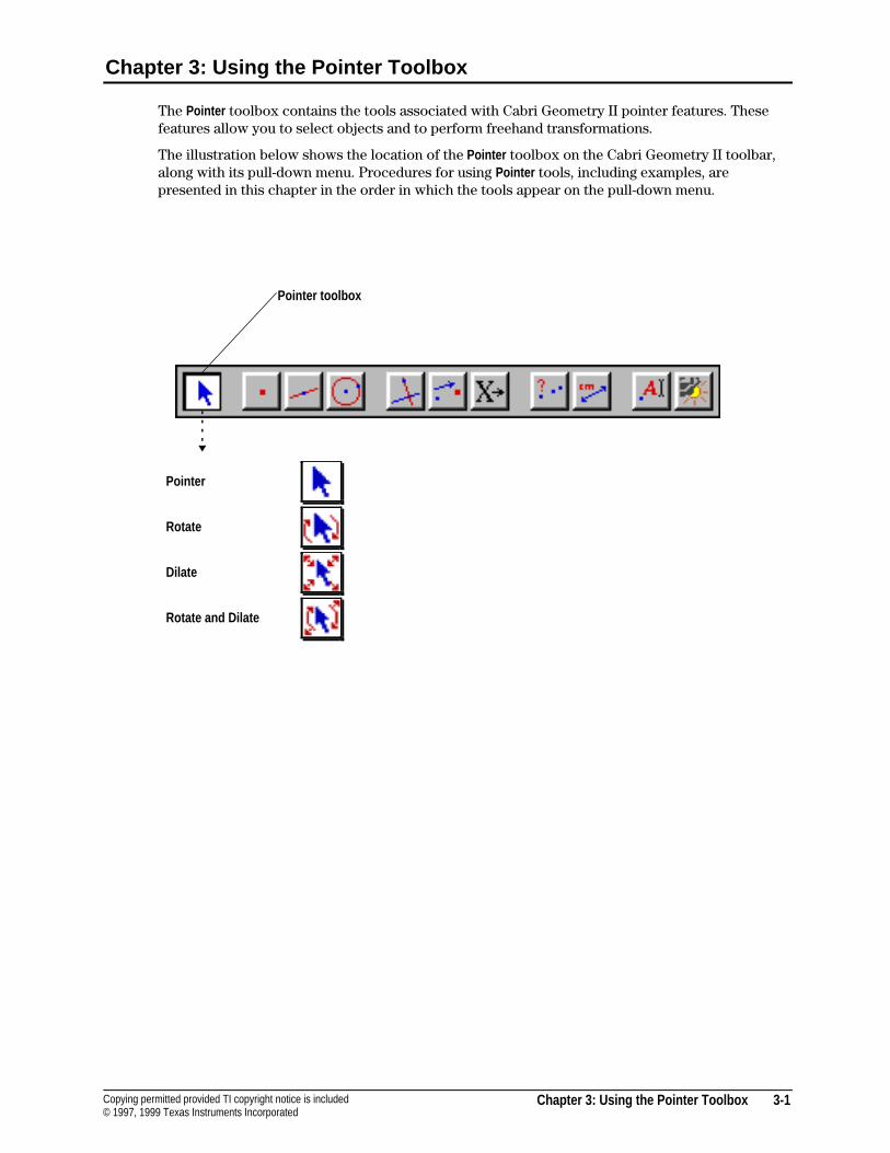
Chapter 3: Using the Pointer Toolbox 3-1Copying permitted provided TI copyright notice is included© 1997, 1999 Texas Instruments Incorporated
Chapter 3: Using the Pointer Toolbox
The Pointer toolbox contains the tools associated with Cabri Geometry II pointer features. Thesefeatures allow you to select objects and to perform freehand transformations.
The illustration below shows the location of the Pointer toolbox on the Cabri Geometry II toolbar,along with its pull-down menu. Procedures for using Pointer tools, including examples, arepresented in this chapter in the order in which the tools appear on the pull-down menu.
Pointer
Rotate
Dilate
Rotate and Dilate
Pointer toolbox
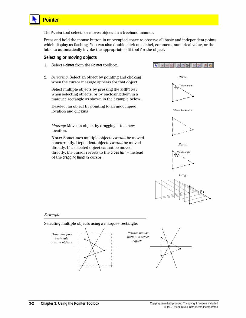
3-2 Chapter 3: Using the Pointer Toolbox Copying permitted provided TI copyright notice is included© 1997, 1999 Texas Instruments Incorporated
Pointer
The Pointer tool selects or moves objects in a freehand manner.
Press and hold the mouse button in unoccupied space to observe all basic and independent pointswhich display as flashing. You can also double-click on a label, comment, numerical value, or thetable to automatically invoke the appropriate edit tool for the object.
Selecting or moving objects
1. Select Pointer from the Pointer toolbox.
2. Selecting: Select an object by pointing and clickingwhen the cursor message appears for that object.
Select multiple objects by pressing the SHIFT keywhen selecting objects, or by enclosing them in amarquee rectangle as shown in the example below.
Deselect an object by pointing to an unoccupiedlocation and clicking.
Moving: Move an object by dragging it to a newlocation.
Note: Sometimes multiple objects cannot be movedconcurrently. Dependent objects cannot be moveddirectly. If a selected object cannot be moveddirectly, the cursor reverts to the cross hair ! insteadof the dragging hand % cursor.
Example
Selecting multiple objects using a marquee rectangle:
Point.
Click to select.
Point.
Drag.
Drag marquee
rectangle
around objects.
Release mouse
button to select
objects.
This triangle
This triangle
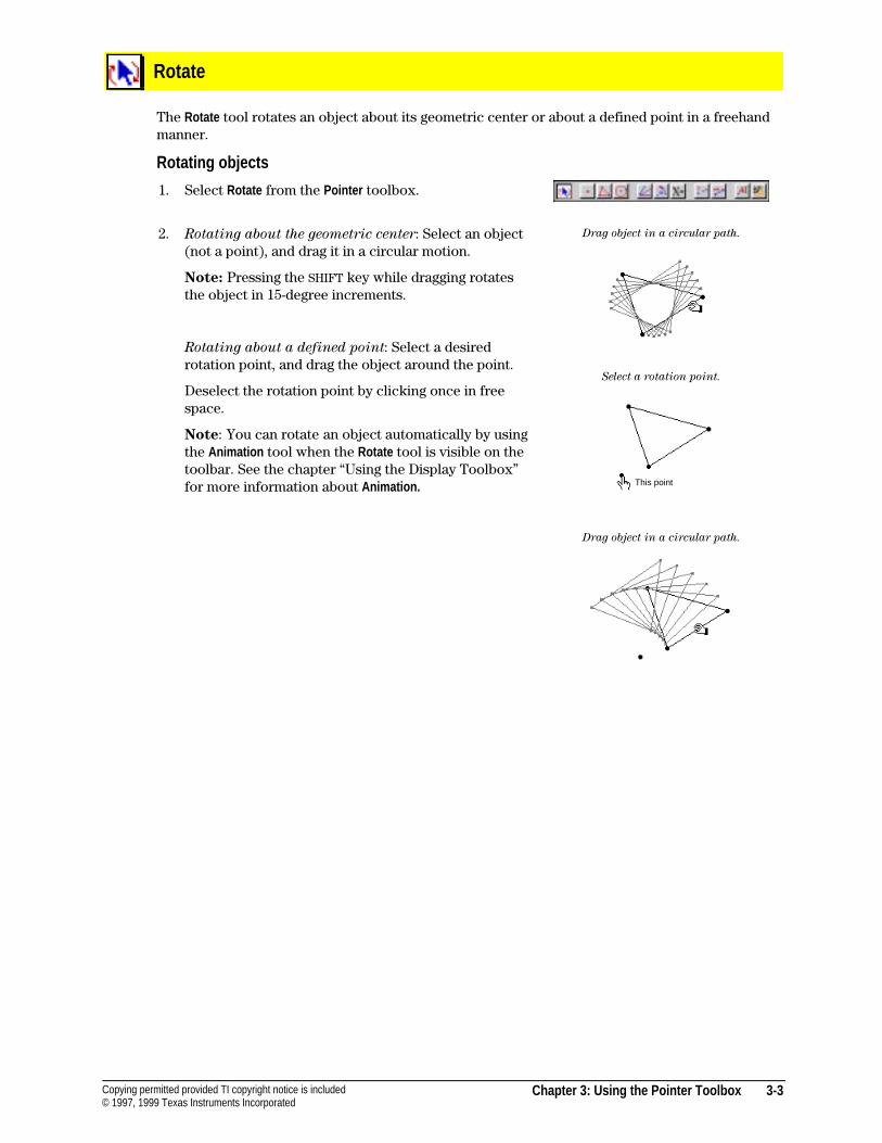
Chapter 3: Using the Pointer Toolbox 3-3Copying permitted provided TI copyright notice is included© 1997, 1999 Texas Instruments Incorporated
Rotate
The Rotate tool rotates an object about its geometric center or about a defined point in a freehandmanner.
Rotating objects
1. Select Rotate from the Pointer toolbox.
2. Rotating about the geometric center: Select an object(not a point), and drag it in a circular motion.
Note: Pressing the SHIFT key while dragging rotatesthe object in 15-degree increments.
Rotating about a defined point: Select a desiredrotation point, and drag the object around the point.
Deselect the rotation point by clicking once in freespace.
Note: You can rotate an object automatically by usingthe Animation tool when the Rotate tool is visible on thetoolbar. See the chapter “Using the Display Toolbox”for more information about Animation.
Drag object in a circular path.
Select a rotation point.
Drag object in a circular path.
This point
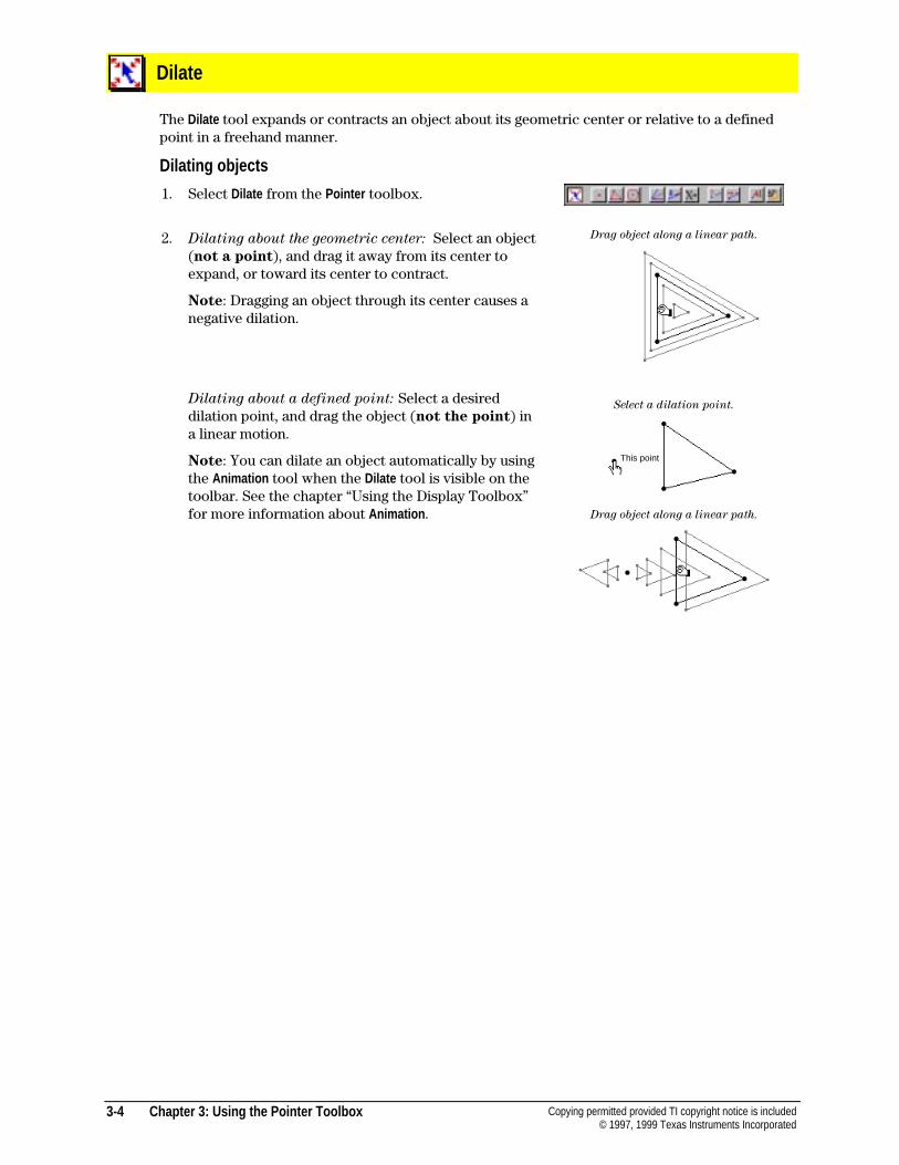
3-4 Chapter 3: Using the Pointer Toolbox Copying permitted provided TI copyright notice is included© 1997, 1999 Texas Instruments Incorporated
Dilate
The Dilate tool expands or contracts an object about its geometric center or relative to a definedpoint in a freehand manner.
Dilating objects
1. Select Dilate from the Pointer toolbox.
2. Dilating about the geometric center: Select an object(not a point), and drag it away from its center toexpand, or toward its center to contract.
Note: Dragging an object through its center causes anegative dilation.
Dilating about a defined point: Select a desireddilation point, and drag the object (not the point) ina linear motion.
Note: You can dilate an object automatically by usingthe Animation tool when the Dilate tool is visible on thetoolbar. See the chapter “Using the Display Toolbox”for more information about Animation .
Drag object along a linear path.
Select a dilation point.
Drag object along a linear path.
This point
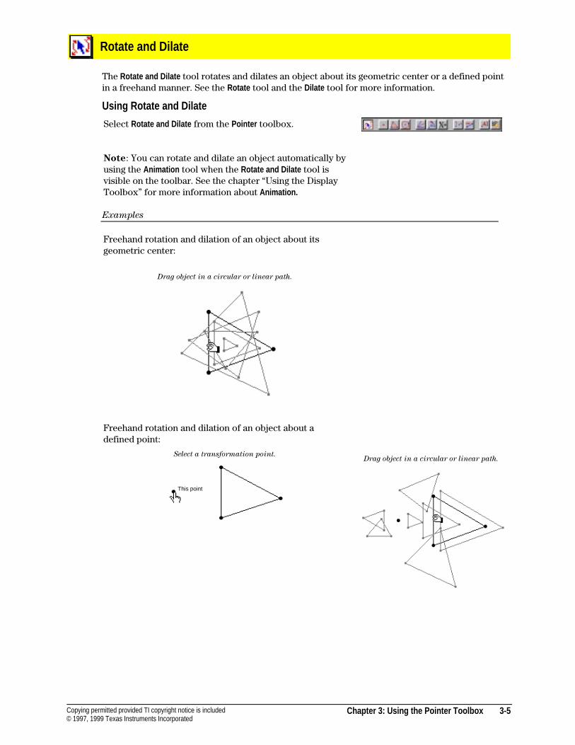
Chapter 3: Using the Pointer Toolbox 3-5Copying permitted provided TI copyright notice is included© 1997, 1999 Texas Instruments Incorporated
Rotate and Dilate
The Rotate and Dilate tool rotates and dilates an object about its geometric center or a defined pointin a freehand manner. See the Rotate tool and the Dilate tool for more information.
Using Rotate and Dilate
Select Rotate and Dilate from the Pointer toolbox.
Note: You can rotate and dilate an object automatically byusing the Animation tool when the Rotate and Dilate tool isvisible on the toolbar. See the chapter “Using the DisplayToolbox” for more information about Animation.
Examples
Freehand rotation and dilation of an object about itsgeometric center:
Drag object in a circular or linear path.
Freehand rotation and dilation of an object about adefined point:
Select a transformation point.Drag object in a circular or linear path.
This point
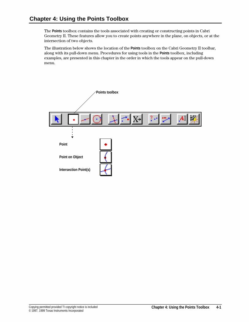
Chapter 4: Using the Points Toolbox 4-1Copying permitted provided TI copyright notice is included© 1997, 1999 Texas Instruments Incorporated
Chapter 4: Using the Points Toolbox
The Points toolbox contains the tools associated with creating or constructing points in CabriGeometry II. These features allow you to create points anywhere in the plane, on objects, or at theintersection of two objects.
The illustration below shows the location of the Points toolbox on the Cabri Geometry II toolbar,along with its pull-down menu. Procedures for using tools in the Points toolbox, includingexamples, are presented in this chapter in the order in which the tools appear on the pull-downmenu.
Point
Point on Object
Intersection Point(s)
Points toolbox
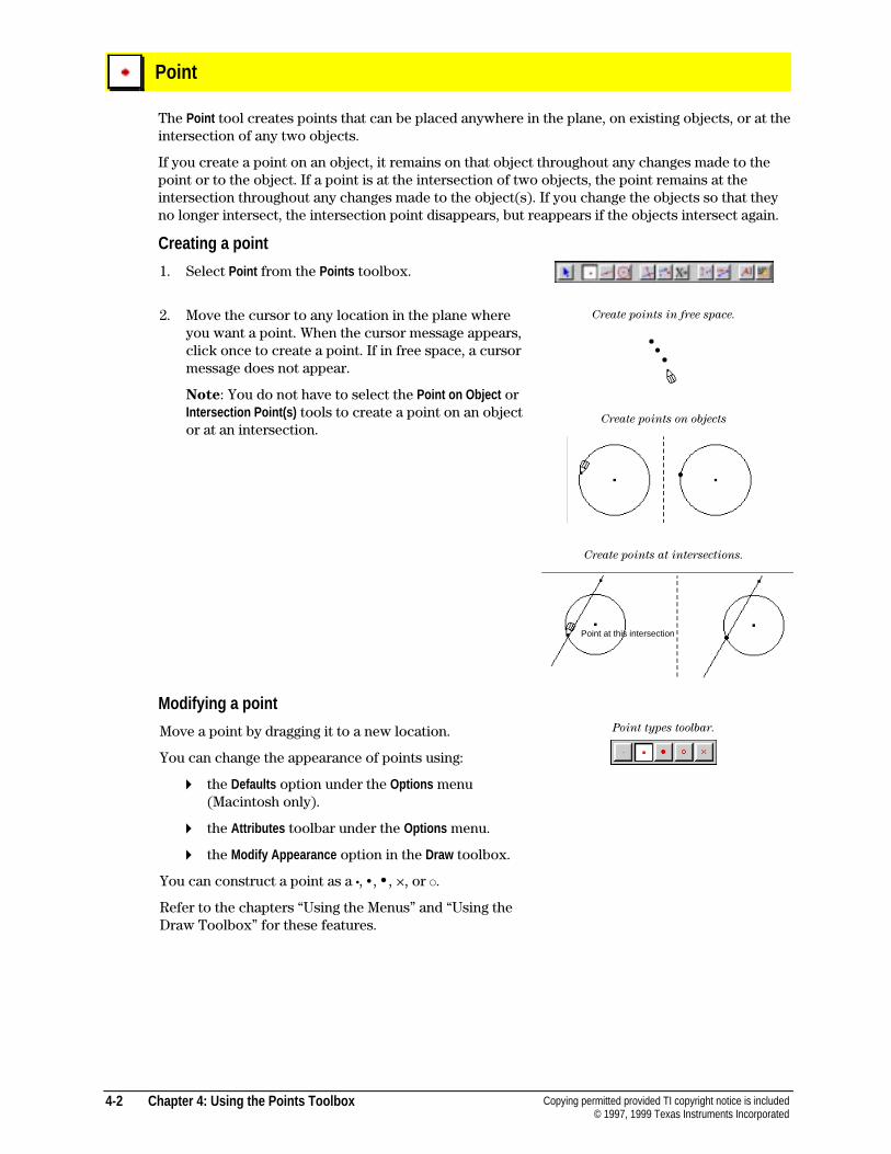
4-2 Chapter 4: Using the Points Toolbox Copying permitted provided TI copyright notice is included© 1997, 1999 Texas Instruments Incorporated
Point
The Point tool creates points that can be placed anywhere in the plane, on existing objects, or at theintersection of any two objects.
If you create a point on an object, it remains on that object throughout any changes made to thepoint or to the object. If a point is at the intersection of two objects, the point remains at theintersection throughout any changes made to the object(s). If you change the objects so that theyno longer intersect, the intersection point disappears, but reappears if the objects intersect again.
Creating a point
1. Select Point from the Points toolbox.
2. Move the cursor to any location in the plane whereyou want a point. When the cursor message appears,click once to create a point. If in free space, a cursormessage does not appear.
Note: You do not have to select the Point on Object orIntersection Point(s) tools to create a point on an objector at an intersection.
Create points in free space.
Create points on objects
Create points at intersections.
Modifying a point
Move a point by dragging it to a new location.
You can change the appearance of points using:
4 the Defaults option under the Options menu(Macintosh only).
4 the Attributes toolbar under the Options menu.
4 the Modify Appearance option in the Draw toolbox.
You can construct a point as a ¦, •, •, ×, or ™.
Refer to the chapters “Using the Menus” and “Using theDraw Toolbox” for these features.
Point types toolbar.
Point at this intersection
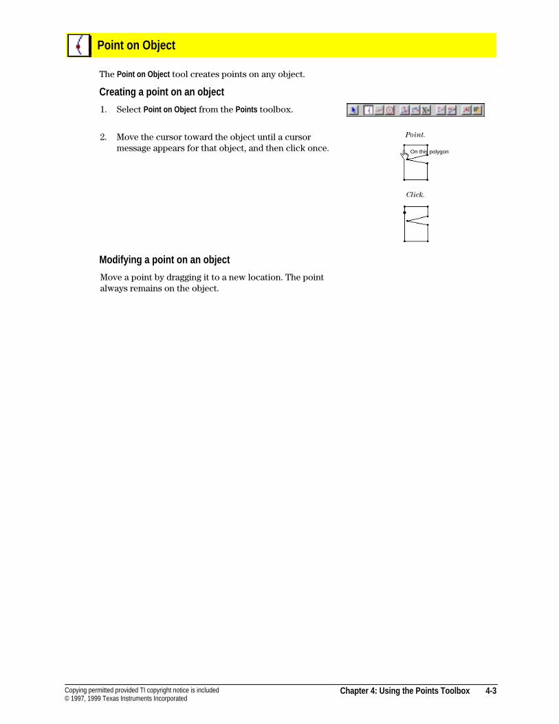
Chapter 4: Using the Points Toolbox 4-3Copying permitted provided TI copyright notice is included© 1997, 1999 Texas Instruments Incorporated
Point on Object
The Point on Object tool creates points on any object.
Creating a point on an object
1. Select Point on Object from the Points toolbox.
2. Move the cursor toward the object until a cursormessage appears for that object, and then click once.
Point.
Click.
Modifying a point on an object
Move a point by dragging it to a new location. The pointalways remains on the object.
On this polygon
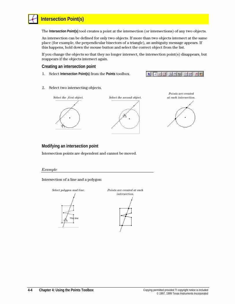
4-4 Chapter 4: Using the Points Toolbox Copying permitted provided TI copyright notice is included© 1997, 1999 Texas Instruments Incorporated
Intersection Point(s)
The Intersection Point(s) tool creates a point at the intersection (or intersections) of any two objects.
An intersection can be defined for only two objects. If more than two objects intersect at the sameplace (for example, the perpendicular bisectors of a triangle), an ambiguity message appears. Ifthis happens, hold down the mouse button and select the correct object from the list.
If you change the objects so that they no longer intersect, the intersection point(s) disappears, butreappears if the objects intersect again.
Creating an intersection point
1. Select Intersection Point(s) from the Points toolbox.
2. Select two intersecting objects.
Select the first object. Select the second object.
Points are created
at each intersection.
Modifying an intersection point
Intersection points are dependent and cannot be moved.
Example
Intersection of a line and a polygon:
Select polygon and line. Points are created at each
intersection.
This line
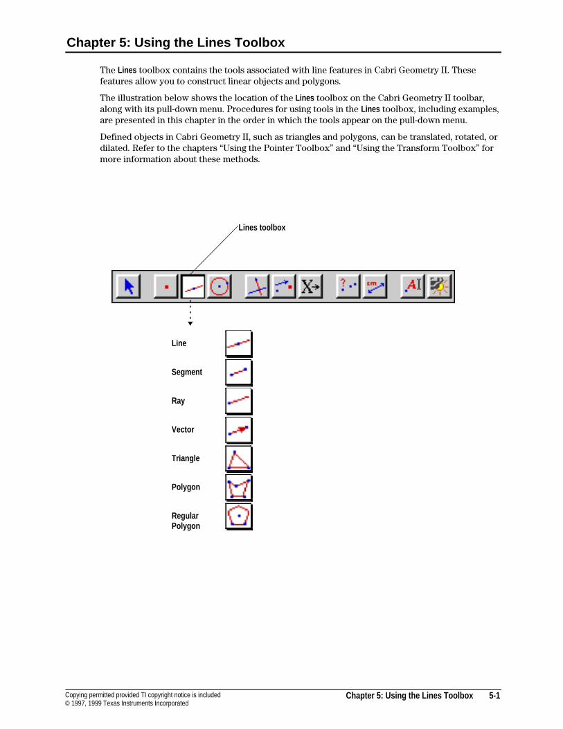
Chapter 5: Using the Lines Toolbox 5-1Copying permitted provided TI copyright notice is included© 1997, 1999 Texas Instruments Incorporated
Chapter 5: Using the Lines Toolbox
The Lines toolbox contains the tools associated with line features in Cabri Geometry II. Thesefeatures allow you to construct linear objects and polygons.
The illustration below shows the location of the Lines toolbox on the Cabri Geometry II toolbar,along with its pull-down menu. Procedures for using tools in the Lines toolbox, including examples,are presented in this chapter in the order in which the tools appear on the pull-down menu.
Defined objects in Cabri Geometry II, such as triangles and polygons, can be translated, rotated, ordilated. Refer to the chapters “Using the Pointer Toolbox” and “Using the Transform Toolbox” formore information about these methods.
Line
Segment
Ray
Vector
Triangle
Polygon
RegularPolygon
Lines toolbox
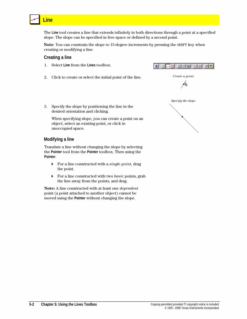
5-2 Chapter 5: Using the Lines Toolbox Copying permitted provided TI copyright notice is included© 1997, 1999 Texas Instruments Incorporated
Line
The Line tool creates a line that extends infinitely in both directions through a point at a specifiedslope. The slope can be specified in free space or defined by a second point.
Note: You can constrain the slope to 15-degree increments by pressing the SHIFT key whencreating or modifying a line.
Creating a line
1. Select Line from the Lines toolbox.
2. Click to create or select the initial point of the line.
3. Specify the slope by positioning the line in thedesired orientation and clicking.
When specifying slope, you can create a point on anobject, select an existing point, or click inunoccupied space.
Create a point.
Specify the slope.
Modifying a line
Translate a line without changing the slope by selectingthe Pointer tool from the Pointer toolbox. Then using thePointer :
4 For a line constructed with a single point, dragthe point.
4 For a line constructed with two basic points, grabthe line away from the points, and drag.
Note: A line constructed with at least one dependent
point (a point attached to another object) cannot bemoved using the Pointer without changing the slope.
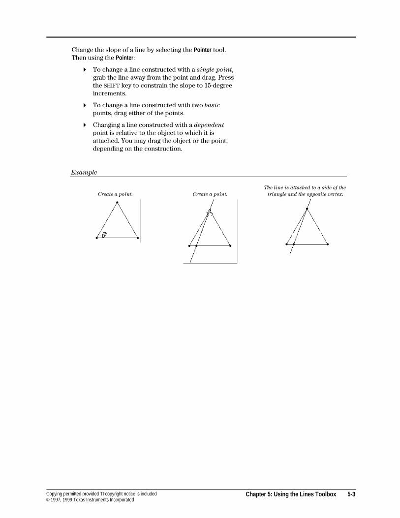
Chapter 5: Using the Lines Toolbox 5-3Copying permitted provided TI copyright notice is included© 1997, 1999 Texas Instruments Incorporated
Change the slope of a line by selecting the Pointer tool.Then using the Pointer :
4 To change a line constructed with a single point,grab the line away from the point and drag. Pressthe SHIFT key to constrain the slope to 15-degreeincrements.
4 To change a line constructed with two basic
points, drag either of the points.
4 Changing a line constructed with a dependent
point is relative to the object to which it isattached. You may drag the object or the point,depending on the construction.
Example
Create a point. Create a point.
The line is attached to a side of the
triangle and the opposite vertex.
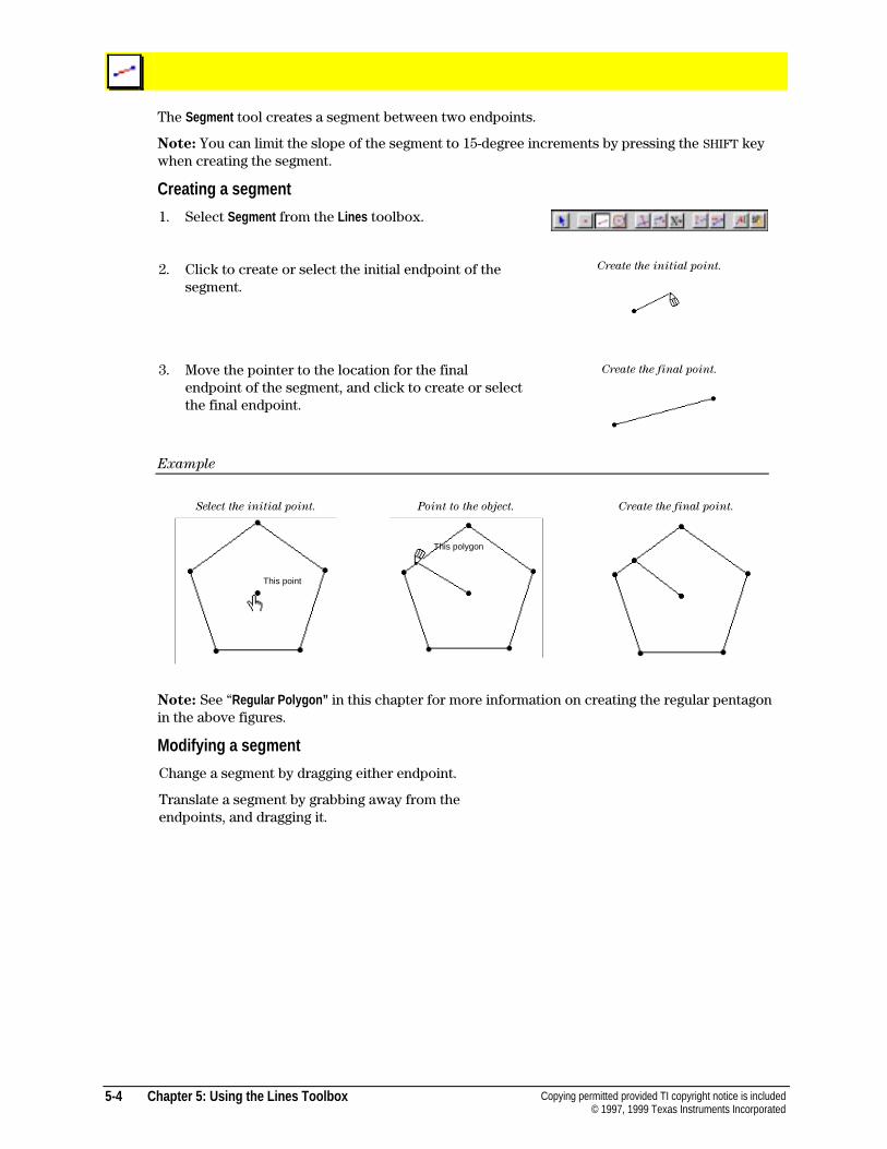
5-4 Chapter 5: Using the Lines Toolbox Copying permitted provided TI copyright notice is included© 1997, 1999 Texas Instruments Incorporated
The Segment tool creates a segment between two endpoints.
Note: You can limit the slope of the segment to 15-degree increments by pressing the SHIFT keywhen creating the segment.
Creating a segment
1. Select Segment from the Lines toolbox.
2. Click to create or select the initial endpoint of thesegment.
Create the initial point.
3. Move the pointer to the location for the finalendpoint of the segment, and click to create or selectthe final endpoint.
Create the final point.
Example
Select the initial point. Point to the object. Create the final point.
Note: See “Regular Polygon” in this chapter for more information on creating the regular pentagonin the above figures.
Modifying a segment
Change a segment by dragging either endpoint.
Translate a segment by grabbing away from theendpoints, and dragging it.
This point
This polygon
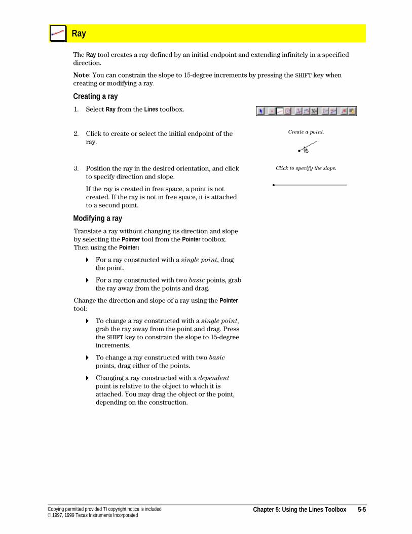
Chapter 5: Using the Lines Toolbox 5-5Copying permitted provided TI copyright notice is included© 1997, 1999 Texas Instruments Incorporated
Ray
The Ray tool creates a ray defined by an initial endpoint and extending infinitely in a specifieddirection.
Note: You can constrain the slope to 15-degree increments by pressing the SHIFT key whencreating or modifying a ray.
Creating a ray
1. Select Ray from the Lines toolbox.
2. Click to create or select the initial endpoint of theray.
Create a point.
3. Position the ray in the desired orientation, and clickto specify direction and slope.
If the ray is created in free space, a point is notcreated. If the ray is not in free space, it is attachedto a second point.
Click to specify the slope.
Modifying a ray
Translate a ray without changing its direction and slopeby selecting the Pointer tool from the Pointer toolbox.Then using the Pointer :
4 For a ray constructed with a single point, dragthe point.
4 For a ray constructed with two basic points, grabthe ray away from the points and drag.
Change the direction and slope of a ray using the Pointertool:
4 To change a ray constructed with a single point,grab the ray away from the point and drag. Pressthe SHIFT key to constrain the slope to 15-degreeincrements.
4 To change a ray constructed with two basic
points, drag either of the points.
4 Changing a ray constructed with a dependent
point is relative to the object to which it isattached. You may drag the object or the point,depending on the construction.
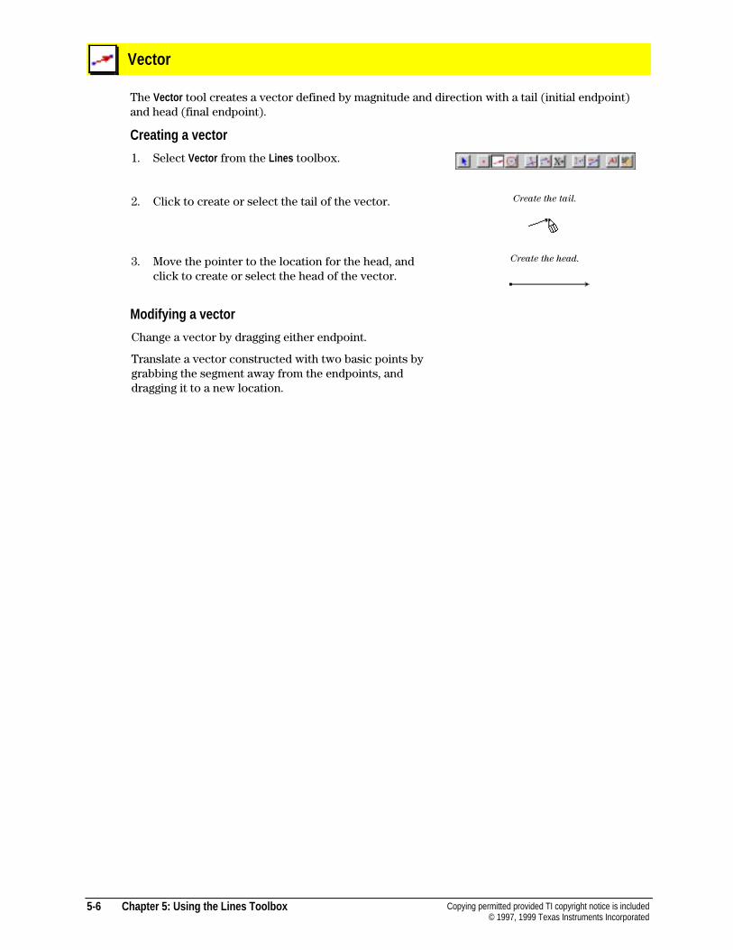
5-6 Chapter 5: Using the Lines Toolbox Copying permitted provided TI copyright notice is included© 1997, 1999 Texas Instruments Incorporated
Vector
The Vector tool creates a vector defined by magnitude and direction with a tail (initial endpoint)and head (final endpoint).
Creating a vector
1. Select Vector from the Lines toolbox.
2. Click to create or select the tail of the vector. Create the tail.
3. Move the pointer to the location for the head, andclick to create or select the head of the vector.
Create the head.
Modifying a vector
Change a vector by dragging either endpoint.
Translate a vector constructed with two basic points bygrabbing the segment away from the endpoints, anddragging it to a new location.
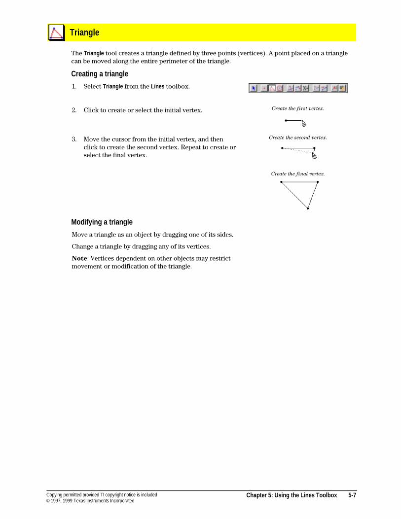
Chapter 5: Using the Lines Toolbox 5-7Copying permitted provided TI copyright notice is included© 1997, 1999 Texas Instruments Incorporated
Triangle
The Triangle tool creates a triangle defined by three points (vertices). A point placed on a trianglecan be moved along the entire perimeter of the triangle.
Creating a triangle
1. Select Triangle from the Lines toolbox.
2. Click to create or select the initial vertex. Create the first vertex.
3. Move the cursor from the initial vertex, and thenclick to create the second vertex. Repeat to create orselect the final vertex.
Create the second vertex.
Create the final vertex.
Modifying a triangle
Move a triangle as an object by dragging one of its sides.
Change a triangle by dragging any of its vertices.
Note: Vertices dependent on other objects may restrictmovement or modification of the triangle.
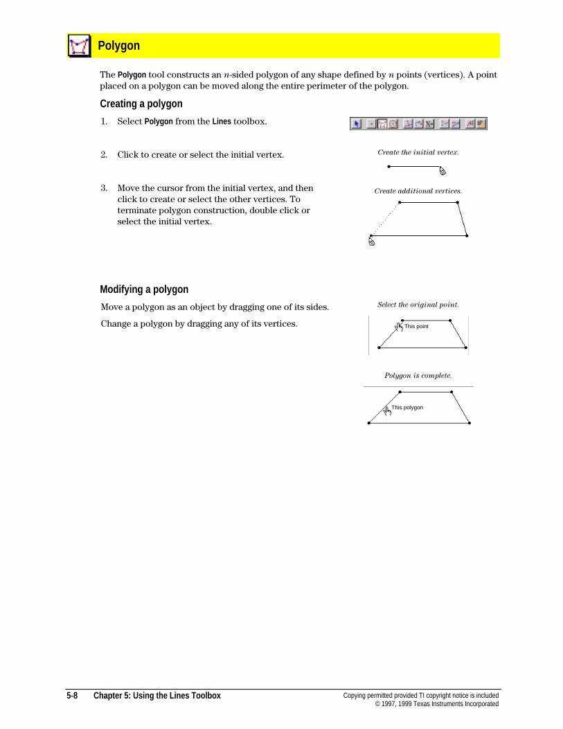
5-8 Chapter 5: Using the Lines Toolbox Copying permitted provided TI copyright notice is included© 1997, 1999 Texas Instruments Incorporated
Polygon
The Polygon tool constructs an n-sided polygon of any shape defined by n points (vertices). A pointplaced on a polygon can be moved along the entire perimeter of the polygon.
Creating a polygon
1. Select Polygon from the Lines toolbox.
2. Click to create or select the initial vertex.
3. Move the cursor from the initial vertex, and thenclick to create or select the other vertices. Toterminate polygon construction, double click orselect the initial vertex.
Create the initial vertex.
Create additional vertices.
Modifying a polygon
Move a polygon as an object by dragging one of its sides.
Change a polygon by dragging any of its vertices.
Select the original point.
Polygon is complete.
This point
This polygon
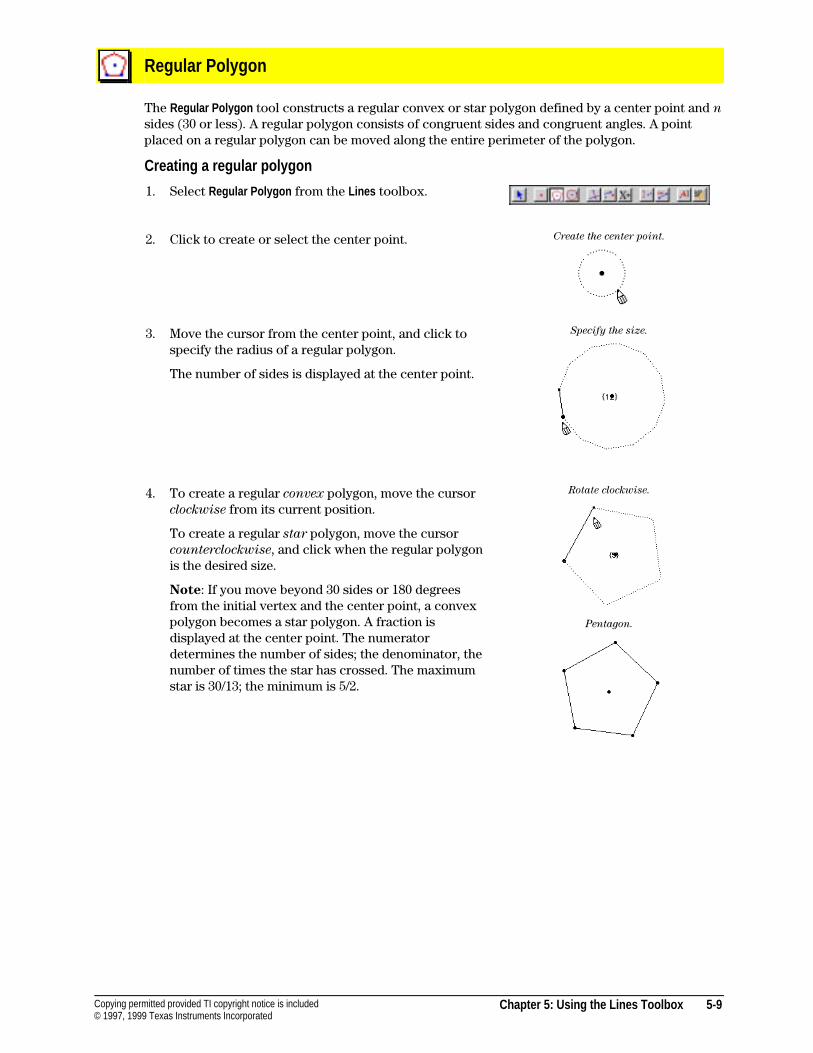
Chapter 5: Using the Lines Toolbox 5-9Copying permitted provided TI copyright notice is included© 1997, 1999 Texas Instruments Incorporated
Regular Polygon
The Regular Polygon tool constructs a regular convex or star polygon defined by a center point and nsides (30 or less). A regular polygon consists of congruent sides and congruent angles. A pointplaced on a regular polygon can be moved along the entire perimeter of the polygon.
Creating a regular polygon
1. Select Regular Polygon from the Lines toolbox.
2. Click to create or select the center point. Create the center point.
3. Move the cursor from the center point, and click tospecify the radius of a regular polygon.
The number of sides is displayed at the center point.
Specify the size.
4. To create a regular convex polygon, move the cursorclockwise from its current position.
To create a regular star polygon, move the cursorcounterclockwise, and click when the regular polygonis the desired size.
Note: If you move beyond 30 sides or 180 degreesfrom the initial vertex and the center point, a convexpolygon becomes a star polygon. A fraction isdisplayed at the center point. The numeratordetermines the number of sides; the denominator, thenumber of times the star has crossed. The maximumstar is 30/13; the minimum is 5/2.
Rotate clockwise.
Pentagon.
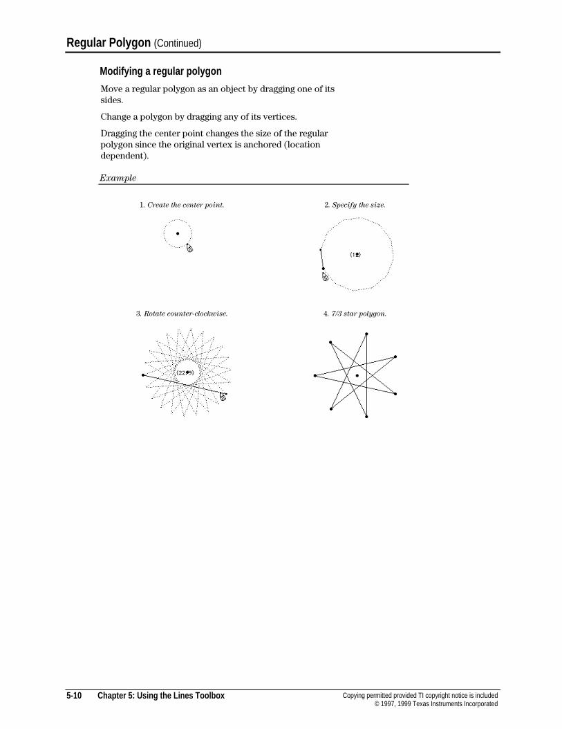
5-10 Chapter 5: Using the Lines Toolbox Copying permitted provided TI copyright notice is included© 1997, 1999 Texas Instruments Incorporated
Regular Polygon (Continued)
Modifying a regular polygon
Move a regular polygon as an object by dragging one of itssides.
Change a polygon by dragging any of its vertices.
Dragging the center point changes the size of the regularpolygon since the original vertex is anchored (locationdependent).
Example
1. Create the center point. 2. Specify the size.
3. Rotate counter-clockwise. 4. 7/3 star polygon.
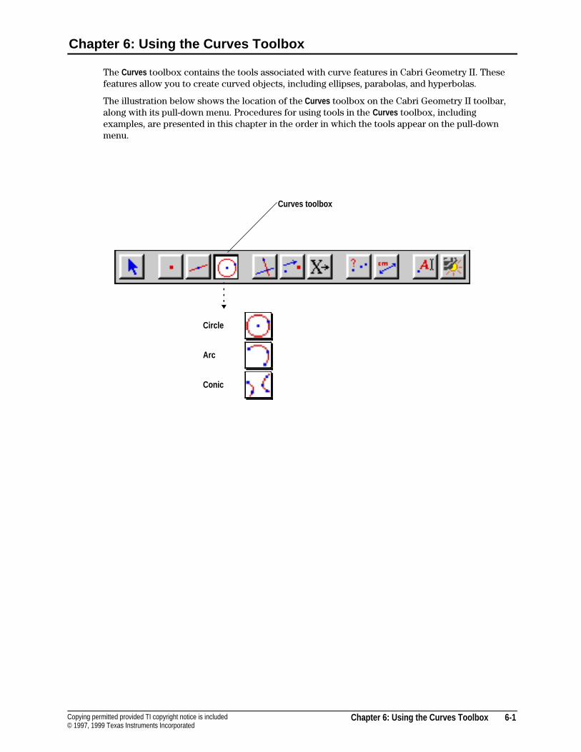
Chapter 6: Using the Curves Toolbox 6-1Copying permitted provided TI copyright notice is included© 1997, 1999 Texas Instruments Incorporated
Chapter 6: Using the Curves Toolbox
The Curves toolbox contains the tools associated with curve features in Cabri Geometry II. Thesefeatures allow you to create curved objects, including ellipses, parabolas, and hyperbolas.
The illustration below shows the location of the Curves toolbox on the Cabri Geometry II toolbar,along with its pull-down menu. Procedures for using tools in the Curves toolbox, includingexamples, are presented in this chapter in the order in which the tools appear on the pull-downmenu.
Circle
Arc
Conic
Curves toolbox
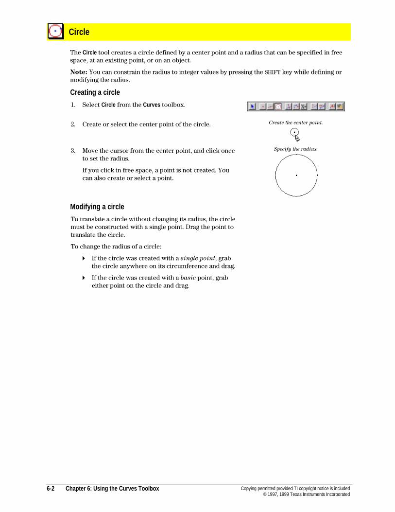
6-2 Chapter 6: Using the Curves Toolbox Copying permitted provided TI copyright notice is included© 1997, 1999 Texas Instruments Incorporated
Circle
The Circle tool creates a circle defined by a center point and a radius that can be specified in freespace, at an existing point, or on an object.
Note: You can constrain the radius to integer values by pressing the SHIFT key while defining ormodifying the radius.
Creating a circle
1. Select Circle from the Curves toolbox.
2. Create or select the center point of the circle. Create the center point.
3. Move the cursor from the center point, and click onceto set the radius.
If you click in free space, a point is not created. Youcan also create or select a point.
Specify the radius.
Modifying a circle
To translate a circle without changing its radius, the circlemust be constructed with a single point. Drag the point totranslate the circle.
To change the radius of a circle:
4 If the circle was created with a single point, grabthe circle anywhere on its circumference and drag.
4 If the circle was created with a basic point, grabeither point on the circle and drag.
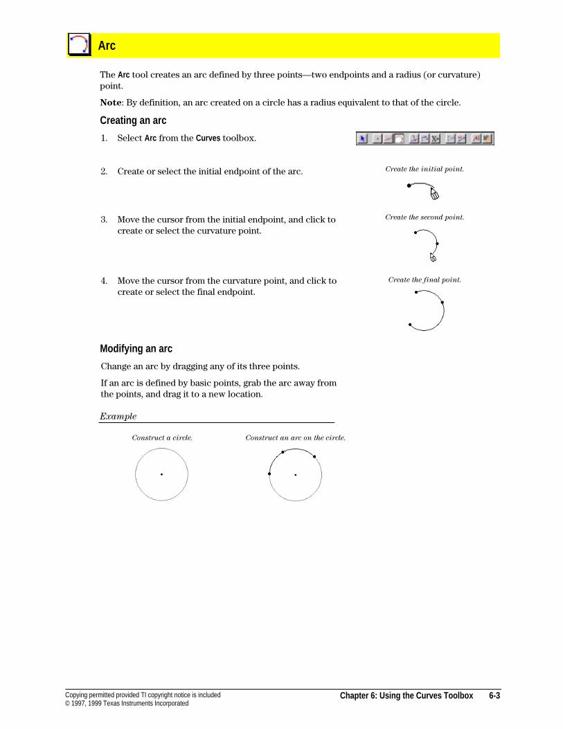
Chapter 6: Using the Curves Toolbox 6-3Copying permitted provided TI copyright notice is included© 1997, 1999 Texas Instruments Incorporated
Arc
The Arc tool creates an arc defined by three points—two endpoints and a radius (or curvature)point.
Note: By definition, an arc created on a circle has a radius equivalent to that of the circle.
Creating an arc
1. Select Arc from the Curves toolbox.
2. Create or select the initial endpoint of the arc. Create the initial point.
3. Move the cursor from the initial endpoint, and click tocreate or select the curvature point.
4. Move the cursor from the curvature point, and click tocreate or select the final endpoint.
Create the second point.
Create the final point.
Modifying an arc
Change an arc by dragging any of its three points.
If an arc is defined by basic points, grab the arc away fromthe points, and drag it to a new location.
Example
Construct a circle. Construct an arc on the circle.
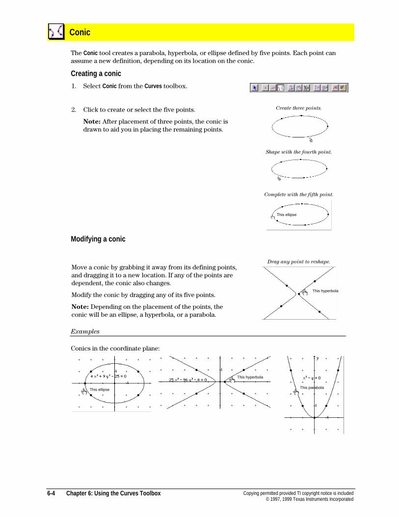
6-4 Chapter 6: Using the Curves Toolbox Copying permitted provided TI copyright notice is included© 1997, 1999 Texas Instruments Incorporated
Conic
The Conic tool creates a parabola, hyperbola, or ellipse defined by five points. Each point canassume a new definition, depending on its location on the conic.
Creating a conic
1. Select Conic from the Curves toolbox.
2. Click to create or select the five points.
Note: After placement of three points, the conic isdrawn to aid you in placing the remaining points.
Create three points.
Shape with the fourth point.
Complete with the fifth point.
Modifying a conic
Move a conic by grabbing it away from its defining points,and dragging it to a new location. If any of the points aredependent, the conic also changes.
Modify the conic by dragging any of its five points.
Note: Depending on the placement of the points, theconic will be an ellipse, a hyperbola, or a parabola.
Drag any point to reshape.
Examples
Conics in the coordinate plane:
This hyperbola
This ellipse
This hyperbola
This parabola
This ellipse
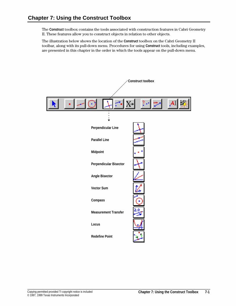
Chapter 7: Using the Construct Toolbox 7-1Copying permitted provided TI copyright notice is included© 1997, 1999 Texas Instruments Incorporated
Chapter 7: Using the Construct Toolbox
The Construct toolbox contains the tools associated with construction features in Cabri GeometryII. These features allow you to construct objects in relation to other objects.
The illustration below shows the location of the Construct toolbox on the Cabri Geometry IItoolbar, along with its pull-down menu. Procedures for using Construct tools, including examples,are presented in this chapter in the order in which the tools appear on the pull-down menu.
Perpendicular Line
Parallel Line
Midpoint
Perpendicular Bisector
Angle Bisector
Vector Sum
Compass
Measurement Transfer
Locus
Redefine Point
Construct toolbox
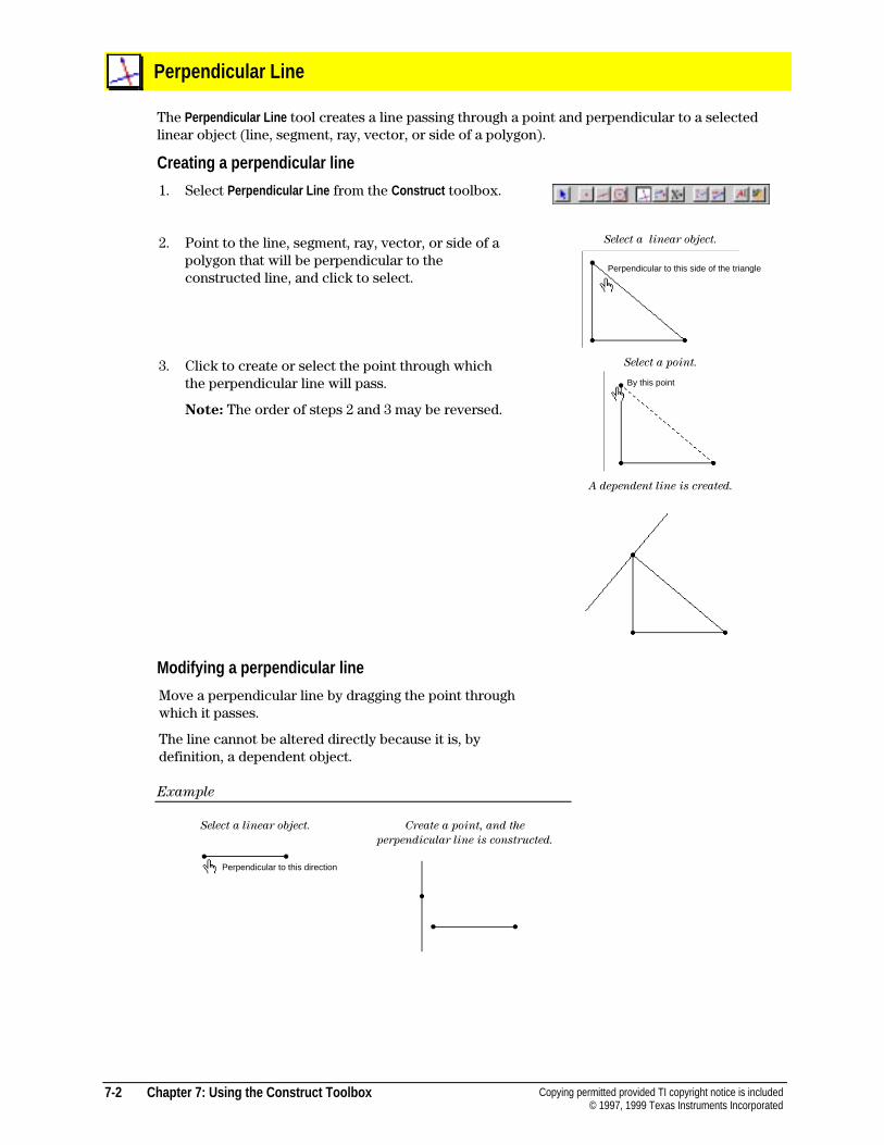
7-2 Chapter 7: Using the Construct Toolbox Copying permitted provided TI copyright notice is included© 1997, 1999 Texas Instruments Incorporated
Perpendicular Line
The Perpendicular Line tool creates a line passing through a point and perpendicular to a selectedlinear object (line, segment, ray, vector, or side of a polygon).
Creating a perpendicular line
1. Select Perpendicular Line from the Construct toolbox.
2. Point to the line, segment, ray, vector, or side of apolygon that will be perpendicular to theconstructed line, and click to select.
Select a linear object.
3. Click to create or select the point through whichthe perpendicular line will pass.
Note: The order of steps 2 and 3 may be reversed.
Select a point.
A dependent line is created.
Modifying a perpendicular line
Move a perpendicular line by dragging the point throughwhich it passes.
The line cannot be altered directly because it is, bydefinition, a dependent object.
Example
Select a linear object. Create a point, and the
perpendicular line is constructed.
Perpendicular to this side of the triangle
By this point
Perpendicular to this direction

Chapter 7: Using the Construct Toolbox 7-3Copying permitted provided TI copyright notice is included© 1997, 1999 Texas Instruments Incorporated
Parallel Line
The Parallel Line tool creates a line that passes through a point and is parallel to a selected linearobject (line, segment, ray, vector, or side of a polygon).
Creating a parallel line
1. Select Parallel Line from the Construct toolbox.
2. Point to the line, segment, ray, vector, or side of apolygon that will be parallel to the constructed lineand click to select.
Select a linear object.
3. Designate the point through which the parallel linewill pass.
Note: The order of steps 2 and 3 may be reversed.
Select a point.
A dependent line is created.
Modifying a parallel line
Move a parallel line by dragging the point throughwhich it passes.
The line cannot be altered directly because it is, bydefinition, a dependent object.
Example
Select a linear object.
Create a point, and the
parallel line is constructed.
Parallel to this side of the triangle
By this point
Parallel to this side of the polygon
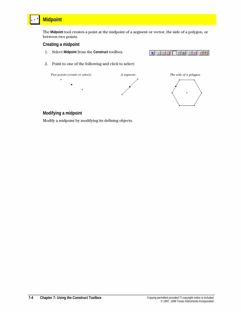
7-4 Chapter 7: Using the Construct Toolbox Copying permitted provided TI copyright notice is included© 1997, 1999 Texas Instruments Incorporated
Midpoint
The Midpoint tool creates a point at the midpoint of a segment or vector, the side of a polygon, orbetween two points.
Creating a midpoint
1. Select Midpoint from the Construct toolbox.
2. Point to one of the following and click to select:
Two points (create or select). A segment. The side of a polygon.
Modifying a midpoint
Modify a midpoint by modifying its defining objects.
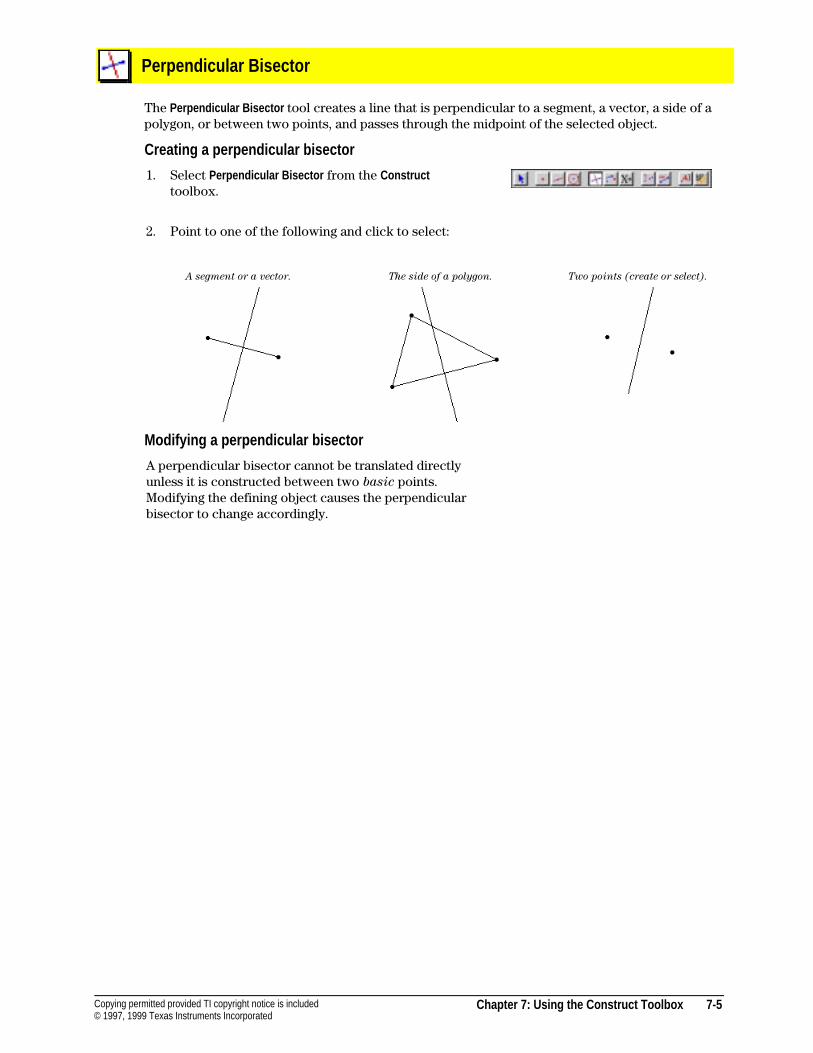
Chapter 7: Using the Construct Toolbox 7-5Copying permitted provided TI copyright notice is included© 1997, 1999 Texas Instruments Incorporated
Perpendicular Bisector
The Perpendicular Bisector tool creates a line that is perpendicular to a segment, a vector, a side of apolygon, or between two points, and passes through the midpoint of the selected object.
Creating a perpendicular bisector
1. Select Perpendicular Bisector from the Constructtoolbox.
2. Point to one of the following and click to select:
A segment or a vector. The side of a polygon. Two points (create or select).
Modifying a perpendicular bisector
A perpendicular bisector cannot be translated directlyunless it is constructed between two basic points.Modifying the defining object causes the perpendicularbisector to change accordingly.
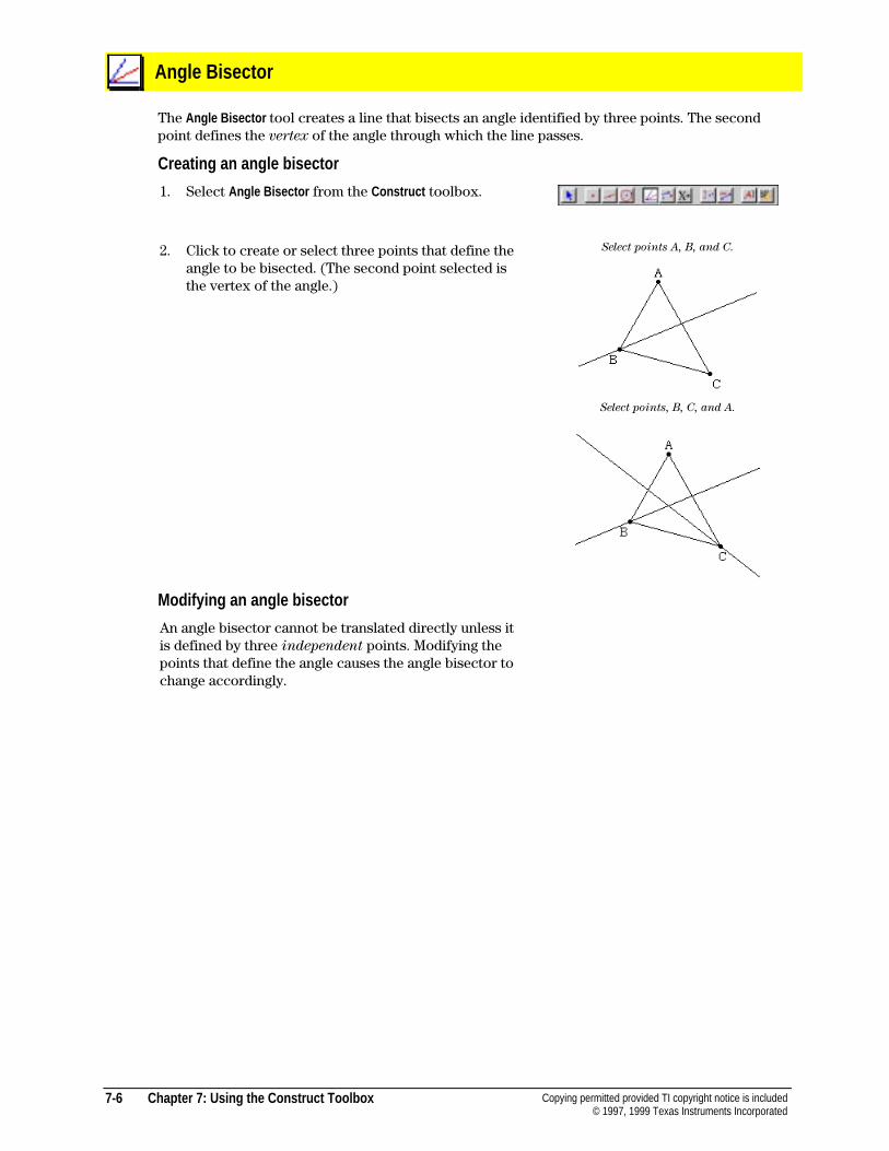
7-6 Chapter 7: Using the Construct Toolbox Copying permitted provided TI copyright notice is included© 1997, 1999 Texas Instruments Incorporated
Angle Bisector
The Angle Bisector tool creates a line that bisects an angle identified by three points. The secondpoint defines the vertex of the angle through which the line passes.
Creating an angle bisector
1. Select Angle Bisector from the Construct toolbox.
2. Click to create or select three points that define theangle to be bisected. (The second point selected isthe vertex of the angle.)
Select points A, B, and C.
Select points, B, C, and A.
Modifying an angle bisector
An angle bisector cannot be translated directly unless itis defined by three independent points. Modifying thepoints that define the angle causes the angle bisector tochange accordingly.
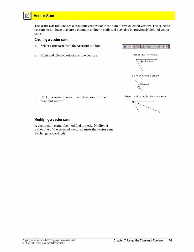
Chapter 7: Using the Construct Toolbox 7-7Copying permitted provided TI copyright notice is included© 1997, 1999 Texas Instruments Incorporated
Vector Sum
The Vector Sum tool creates a resultant vector that is the sum of two selected vectors. The selectedvectors do not have to share a common endpoint (tail) and may also be previously defined vectorsums.
Creating a vector sum
1. Select Vector Sum from the Construct toolbox.
2. Point and click to select any two vectors. Select the first vector.
Select the second vector.
3. Click to create or select the initial point for theresultant vector.
Select a tail point for the vector sum.
Modifying a vector sum
A vector sum cannot be modified directly. Modifyingeither one of the selected vectors causes the vector sumto change accordingly.
This vector
This vector
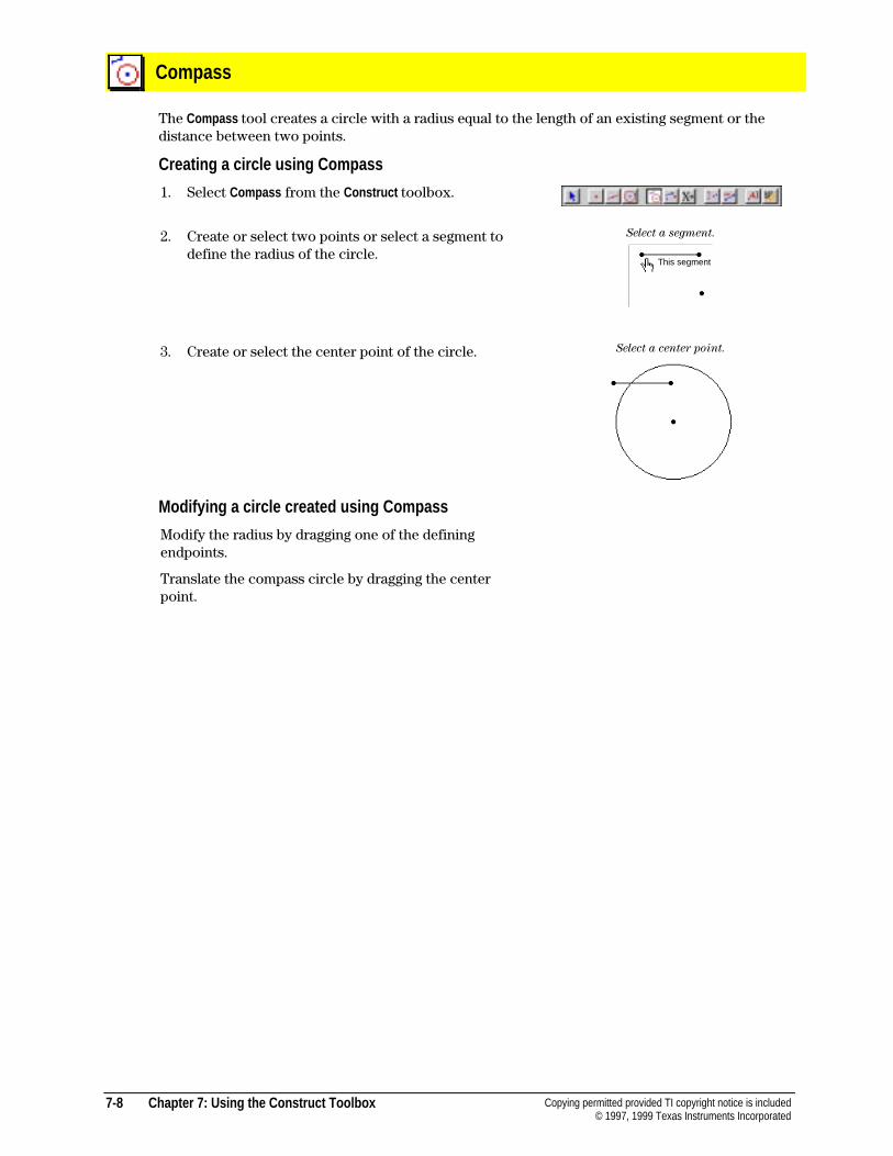
7-8 Chapter 7: Using the Construct Toolbox Copying permitted provided TI copyright notice is included© 1997, 1999 Texas Instruments Incorporated
Compass
The Compass tool creates a circle with a radius equal to the length of an existing segment or thedistance between two points.
Creating a circle using Compass
1. Select Compass from the Construct toolbox.
2. Create or select two points or select a segment todefine the radius of the circle.
Select a segment.
3. Create or select the center point of the circle. Select a center point.
Modifying a circle created using Compass
Modify the radius by dragging one of the definingendpoints.
Translate the compass circle by dragging the centerpoint.
This segment
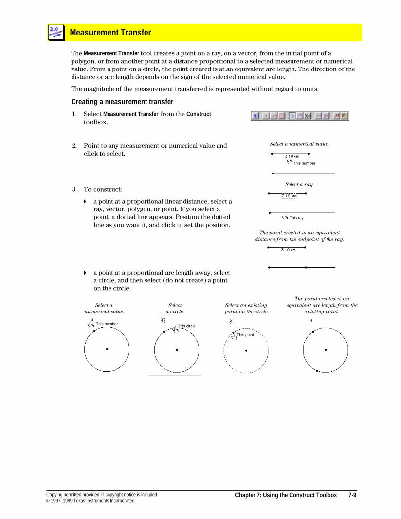
Chapter 7: Using the Construct Toolbox 7-9Copying permitted provided TI copyright notice is included© 1997, 1999 Texas Instruments Incorporated
Measurement Transfer
The Measurement Transfer tool creates a point on a ray, on a vector, from the initial point of apolygon, or from another point at a distance proportional to a selected measurement or numericalvalue. From a point on a circle, the point created is at an equivalent arc length. The direction of thedistance or arc length depends on the sign of the selected numerical value.
The magnitude of the measurement transferred is represented without regard to units.
Creating a measurement transfer
1. Select Measurement Transfer from the Constructtoolbox.
2. Point to any measurement or numerical value andclick to select.
3. To construct:
4 a point at a proportional linear distance, select aray, vector, polygon, or point. If you select apoint, a dotted line appears. Position the dottedline as you want it, and click to set the position.
4 a point at a proportional arc length away, selecta circle, and then select (do not create) a pointon the circle.
Select a numerical value.
Select a ray.
The point created is an equivalent
distance from the endpoint of the ray.
Select a
numerical value.
Select
a circle.
Select an existing
point on the circle.
The point created is an
equivalent arc length from the
existing point.
This ray
This number
This number This circle
This point
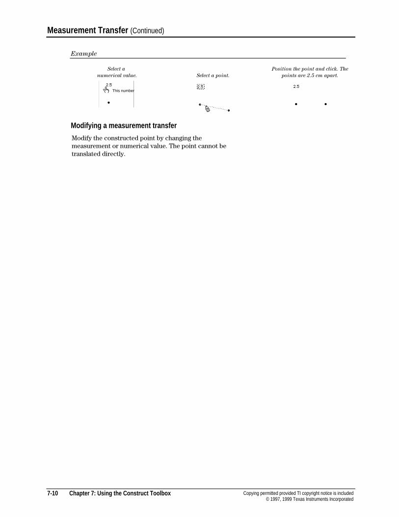
7-10 Chapter 7: Using the Construct Toolbox Copying permitted provided TI copyright notice is included© 1997, 1999 Texas Instruments Incorporated
Measurement Transfer (Continued)
Example
Select a
numerical value. Select a point.
Position the point and click. The
points are 2.5 cm apart.
Modifying a measurement transfer
Modify the constructed point by changing themeasurement or numerical value. The point cannot betranslated directly.
This number
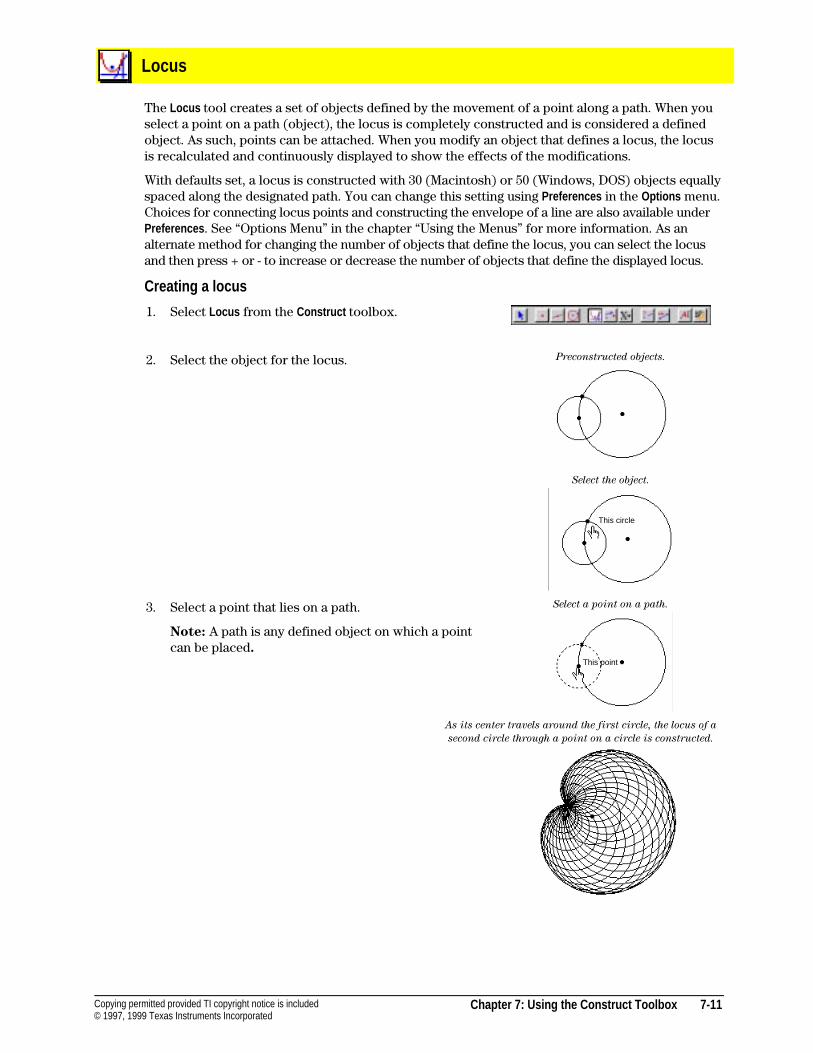
Chapter 7: Using the Construct Toolbox 7-11Copying permitted provided TI copyright notice is included© 1997, 1999 Texas Instruments Incorporated
Locus
The Locus tool creates a set of objects defined by the movement of a point along a path. When youselect a point on a path (object), the locus is completely constructed and is considered a definedobject. As such, points can be attached. When you modify an object that defines a locus, the locusis recalculated and continuously displayed to show the effects of the modifications.
With defaults set, a locus is constructed with 30 (Macintosh) or 50 (Windows, DOS) objects equallyspaced along the designated path. You can change this setting using Preferences in the Options menu.Choices for connecting locus points and constructing the envelope of a line are also available underPreferences . See “Options Menu” in the chapter “Using the Menus” for more information. As analternate method for changing the number of objects that define the locus, you can select the locusand then press + or - to increase or decrease the number of objects that define the displayed locus.
Creating a locus
1. Select Locus from the Construct toolbox.
2. Select the object for the locus. Preconstructed objects.
Select the object.
3. Select a point that lies on a path.
Note: A path is any defined object on which a pointcan be placed.
Select a point on a path.
As its center travels around the first circle, the locus of a
second circle through a point on a circle is constructed.
This circle
This point
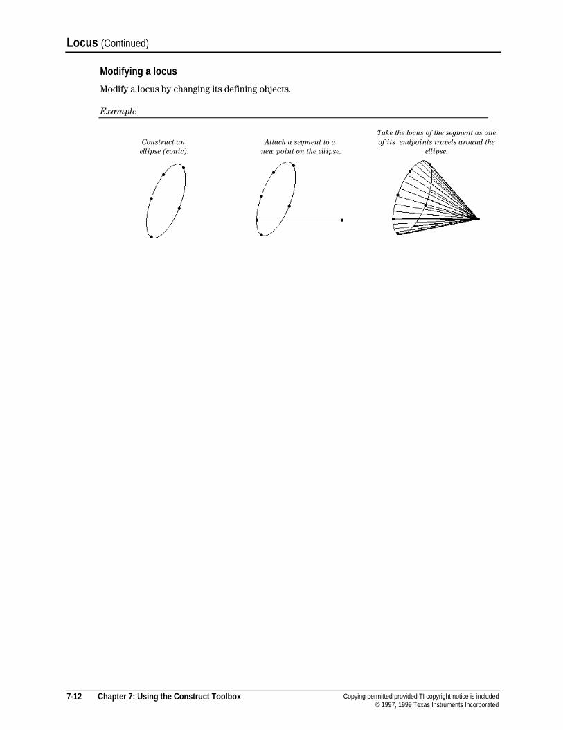
7-12 Chapter 7: Using the Construct Toolbox Copying permitted provided TI copyright notice is included© 1997, 1999 Texas Instruments Incorporated
Locus (Continued)
Modifying a locus
Modify a locus by changing its defining objects.
Example
Construct an
ellipse (conic).
Attach a segment to a
new point on the ellipse.
Take the locus of the segment as one
of its endpoints travels around the
ellipse.
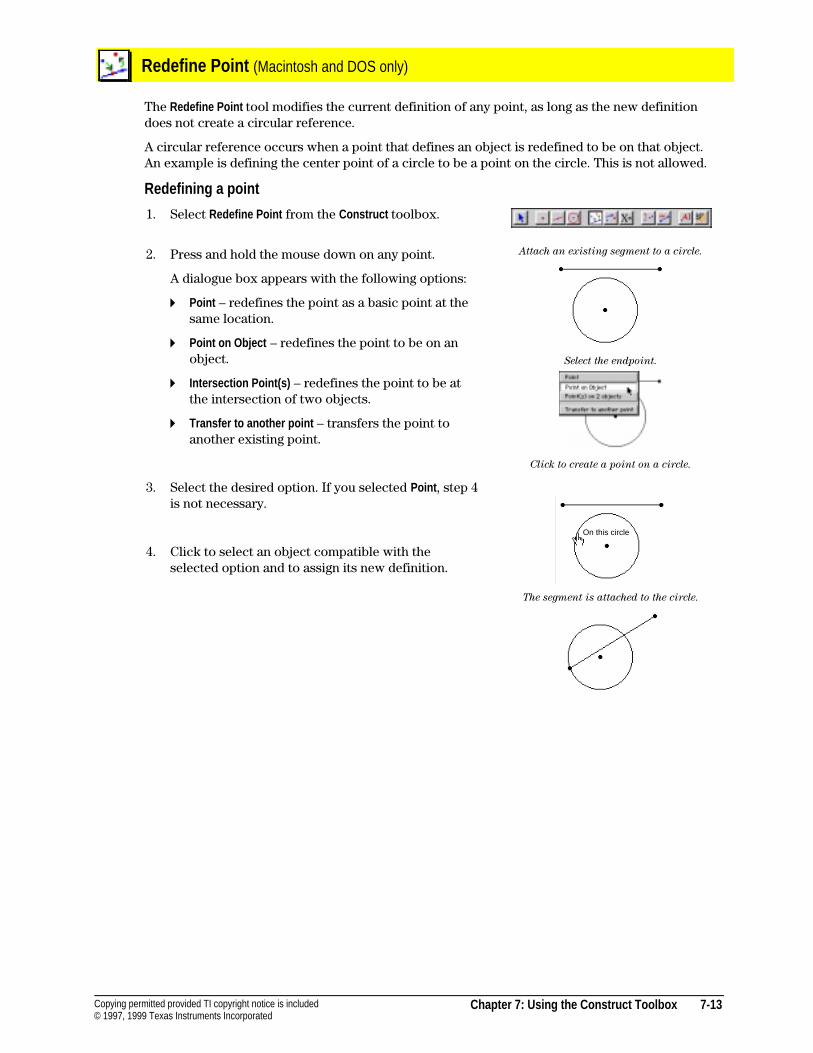
Chapter 7: Using the Construct Toolbox 7-13Copying permitted provided TI copyright notice is included© 1997, 1999 Texas Instruments Incorporated
Redefine Point (Macintosh and DOS only)
The Redefine Point tool modifies the current definition of any point, as long as the new definitiondoes not create a circular reference.
A circular reference occurs when a point that defines an object is redefined to be on that object.An example is defining the center point of a circle to be a point on the circle. This is not allowed.
Redefining a point
1. Select Redefine Point from the Construct toolbox.
2. Press and hold the mouse down on any point.
A dialogue box appears with the following options:
4 Point – redefines the point as a basic point at thesame location.
4 Point on Object – redefines the point to be on anobject.
4 Intersection Point(s) – redefines the point to be atthe intersection of two objects.
4 Transfer to another point – transfers the point toanother existing point.
3. Select the desired option. If you selected Point , step 4is not necessary.
4. Click to select an object compatible with theselected option and to assign its new definition.
Attach an existing segment to a circle.
Select the endpoint.
Click to create a point on a circle.
The segment is attached to the circle.
On this circle

7-14 Chapter 7: Using the Construct Toolbox Copying permitted provided TI copyright notice is included© 1997, 1999 Texas Instruments Incorporated
Redefine Object (Windows only)
The Redefine Object tool modifies the current definition of any object. You can redefine a circle, arc,conic, triangle, segment, ray, vector, polygon, or regular polygon.
Redefining an object
1. Select Redefine Object from the Construct toolbox.
2a. If the object is a point, hold the mouse on the point,and then select the new definition.
4 Point – redefines the point as a basic point.
4 Point on Object – redefines the point to be on anobject.
4 Intersection Point(s) – redefines the point to be atthe intersection of two objects.
4 Transfer to another object – transfers and merges thepoint to another existing point.
A pop-up menu appears with
the following options:
2b. If the object is an object, hold the mouse on theobject, and then select the new definition.
4 Circle, Triangle, Segment, etc. – lets you construct anew object of the same type and automaticallytransfer the original object to it.
4 Transfer to another object – transfers and merges theobject to another existing object of the sametype.
A pop-up menu appears with
the following options:
2c. If the object is a line, hold the mouse on the line, andthen select the new definition.
4 Line – lets you construct a new line andautomatically transfer the original line to it.
4 Perpendicular – redefines the line to beperpendicular to another object.
4 Parallel Line – redefines the line to be parallel toanother object.
4 Perpendicular Bisector – redefines the line to be theperpendicular bisector of another object.
4 Angle Bisector – redefines the line to bisect anangle determined by three points.
4 Transfer to another object – transfers and merges theline to another existing line.
A pop-up menu appears with
the following options:
3. Click to select an object compatible with theselected option and to assign its new definition.
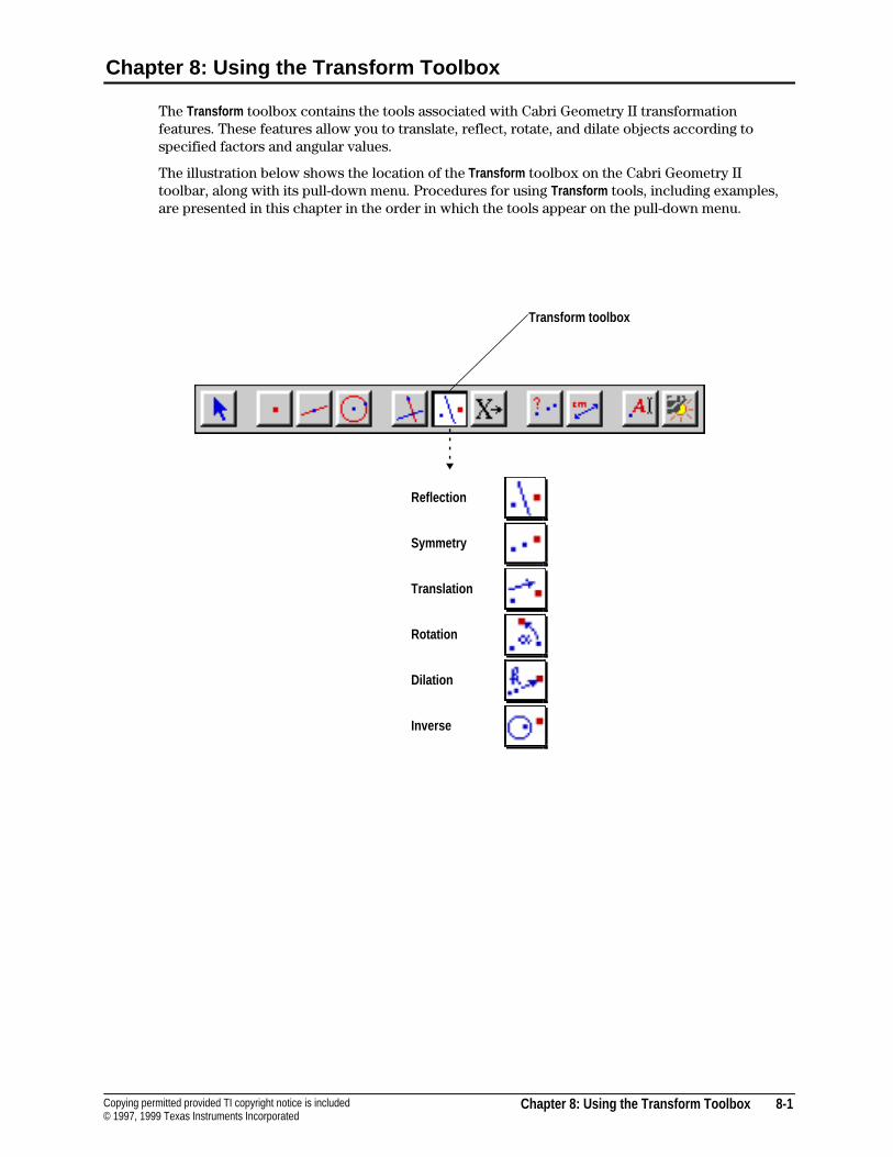
Chapter 8: Using the Transform Toolbox 8-1Copying permitted provided TI copyright notice is included© 1997, 1999 Texas Instruments Incorporated
Chapter 8: Using the Transform Toolbox
The Transform toolbox contains the tools associated with Cabri Geometry II transformationfeatures. These features allow you to translate, reflect, rotate, and dilate objects according tospecified factors and angular values.
The illustration below shows the location of the Transform toolbox on the Cabri Geometry IItoolbar, along with its pull-down menu. Procedures for using Transform tools, including examples,are presented in this chapter in the order in which the tools appear on the pull-down menu.
Reflection
Symmetry
Translation
Rotation
Dilation
Inverse
Transform toolbox
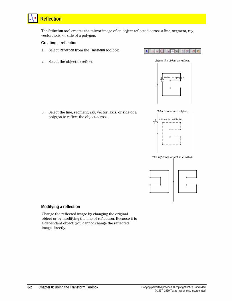
8-2 Chapter 8: Using the Transform Toolbox Copying permitted provided TI copyright notice is included© 1997, 1999 Texas Instruments Incorporated
Reflection
The Reflection tool creates the mirror image of an object reflected across a line, segment, ray,vector, axis, or side of a polygon.
Creating a reflection
1. Select Reflection from the Transform toolbox.
2. Select the object to reflect. Select the object to reflect.
3. Select the line, segment, ray, vector, axis, or side of apolygon to reflect the object across.
Select the linear object.
The reflected object is created.
Modifying a reflection
Change the reflected image by changing the originalobject or by modifying the line of reflection. Because it isa dependent object, you cannot change the reflectedimage directly.
Reflect this polygon
with respect to this line
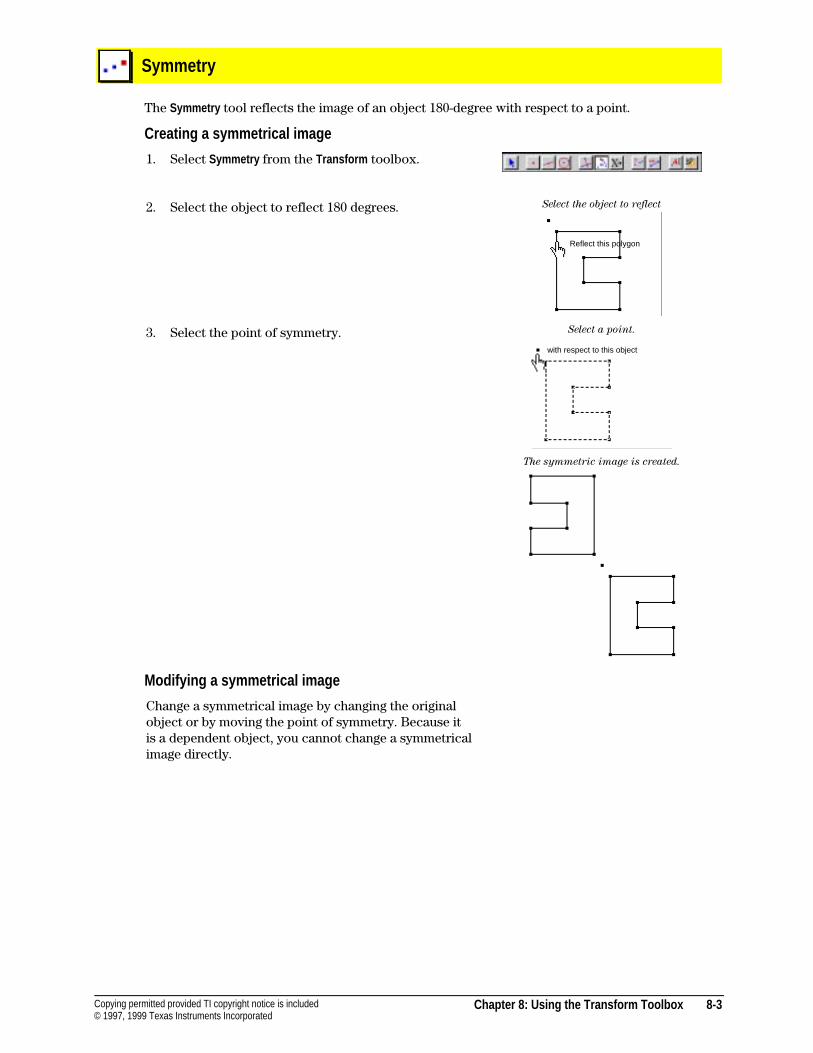
Chapter 8: Using the Transform Toolbox 8-3Copying permitted provided TI copyright notice is included© 1997, 1999 Texas Instruments Incorporated
Symmetry
The Symmetry tool reflects the image of an object 180-degree with respect to a point.
Creating a symmetrical image
1. Select Symmetry from the Transform toolbox.
2. Select the object to reflect 180 degrees. Select the object to reflect
3. Select the point of symmetry. Select a point.
The symmetric image is created.
Modifying a symmetrical image
Change a symmetrical image by changing the originalobject or by moving the point of symmetry. Because itis a dependent object, you cannot change a symmetricalimage directly.
Reflect this polygon
with respect to this object
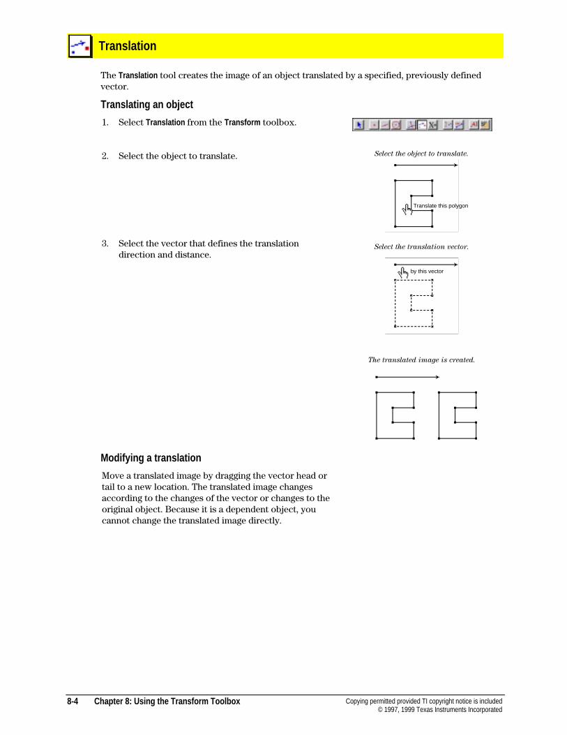
8-4 Chapter 8: Using the Transform Toolbox Copying permitted provided TI copyright notice is included© 1997, 1999 Texas Instruments Incorporated
Translation
The Translation tool creates the image of an object translated by a specified, previously definedvector.
Translating an object
1. Select Translation from the Transform toolbox.
2. Select the object to translate. Select the object to translate.
3. Select the vector that defines the translationdirection and distance.
Select the translation vector.
The translated image is created.
Modifying a translation
Move a translated image by dragging the vector head ortail to a new location. The translated image changesaccording to the changes of the vector or changes to theoriginal object. Because it is a dependent object, youcannot change the translated image directly.
Translate this polygon
by this vector
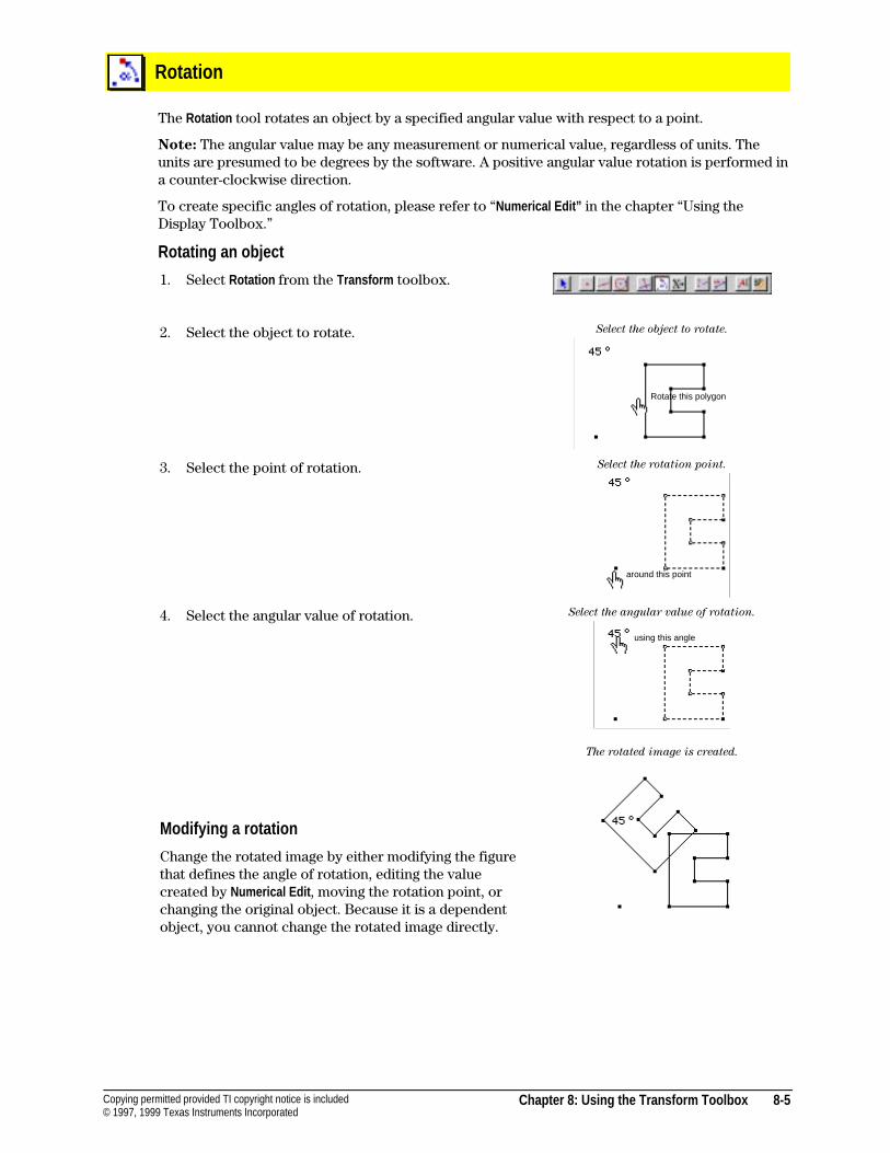
Chapter 8: Using the Transform Toolbox 8-5Copying permitted provided TI copyright notice is included© 1997, 1999 Texas Instruments Incorporated
Rotation
The Rotation tool rotates an object by a specified angular value with respect to a point.
Note: The angular value may be any measurement or numerical value, regardless of units. Theunits are presumed to be degrees by the software. A positive angular value rotation is performed ina counter-clockwise direction.
To create specific angles of rotation, please refer to “Numerical Edit” in the chapter “Using theDisplay Toolbox.”
Rotating an object
1. Select Rotation from the Transform toolbox.
2. Select the object to rotate. Select the object to rotate.
3. Select the point of rotation. Select the rotation point.
4. Select the angular value of rotation.
Modifying a rotation
Change the rotated image by either modifying the figurethat defines the angle of rotation, editing the valuecreated by Numerical Edit , moving the rotation point, orchanging the original object. Because it is a dependentobject, you cannot change the rotated image directly.
Select the angular value of rotation.
The rotated image is created.
Rotate this polygon
around this point
using this angle
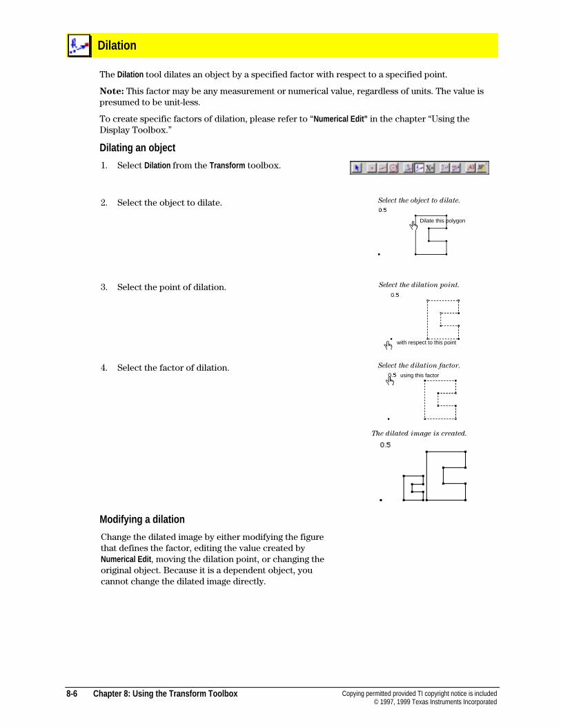
8-6 Chapter 8: Using the Transform Toolbox Copying permitted provided TI copyright notice is included© 1997, 1999 Texas Instruments Incorporated
Dilation
The Dilation tool dilates an object by a specified factor with respect to a specified point.
Note: This factor may be any measurement or numerical value, regardless of units. The value ispresumed to be unit-less.
To create specific factors of dilation, please refer to “Numerical Edit” in the chapter “Using theDisplay Toolbox.”
Dilating an object
1. Select Dilation from the Transform toolbox.
2. Select the object to dilate. Select the object to dilate.
3. Select the point of dilation. Select the dilation point.
4. Select the factor of dilation. Select the dilation factor.
The dilated image is created.
Modifying a dilation
Change the dilated image by either modifying the figurethat defines the factor, editing the value created byNumerical Edit , moving the dilation point, or changing theoriginal object. Because it is a dependent object, youcannot change the dilated image directly.
Dilate this polygon
with respect to this point
using this factor
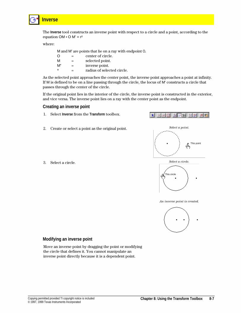
Chapter 8: Using the Transform Toolbox 8-7Copying permitted provided TI copyright notice is included© 1997, 1999 Texas Instruments Incorporated
Inverse
The Inverse tool constructs an inverse point with respect to a circle and a point, according to theequation OM ¦ O M' = r²
where:
M and M' are points that lie on a ray with endpoint O.O = center of circle.M = selected point.M' = inverse point.* = radius of selected circle.
As the selected point approaches the center point, the inverse point approaches a point at infinity.If M is defined to be on a line passing through the circle, the locus of M' constructs a circle thatpasses through the center of the circle.
If the original point lies in the interior of the circle, the inverse point is constructed in the exterior,and vice versa. The inverse point lies on a ray with the center point as the endpoint.
Creating an inverse point
1. Select Inverse from the Transform toolbox.
2. Create or select a point as the original point. Select a point.
3. Select a circle. Select a circle.
An inverse point is created.
Modifying an inverse point
Move an inverse point by dragging the point or modifyingthe circle that defines it. You cannot manipulate aninverse point directly because it is a dependent point.
This point
This circle
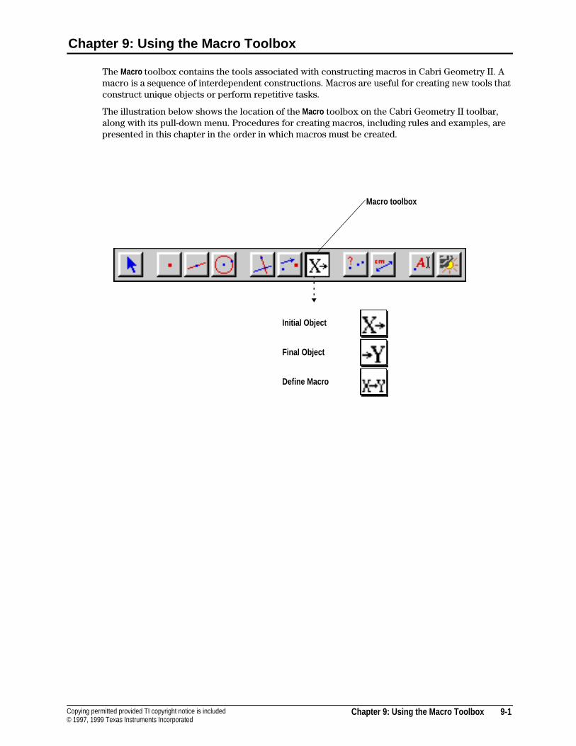
Chapter 9: Using the Macro Toolbox 9-1Copying permitted provided TI copyright notice is included© 1997, 1999 Texas Instruments Incorporated
Chapter 9: Using the Macro Toolbox
The Macro toolbox contains the tools associated with constructing macros in Cabri Geometry II. Amacro is a sequence of interdependent constructions. Macros are useful for creating new tools thatconstruct unique objects or perform repetitive tasks.
The illustration below shows the location of the Macro toolbox on the Cabri Geometry II toolbar,along with its pull-down menu. Procedures for creating macros, including rules and examples, arepresented in this chapter in the order in which macros must be created.
Initial Object
Final Object
Define Macro
Macro toolbox
9-2 Chapter 9: Using the Macro Toolbox Copying permitted provided TI copyright notice is included© 1997, 1999 Texas Instruments Incorporated
How to create a macro
A macro constructs “final” objects based on “initial” objects. Intermediate objects are notconstructed. This feature allows easy construction of complex figures and is the primary methodfor constructing fractals. You can save macros on disk for later use. Macros are automaticallysaved with any file in which they are used.
To create a macro:
1. Select the initial objects required to define the final object(s).
2. Select the final object(s), and then, if necessary, change the attributes of the object(s) as theywill appear in the final construction.
3. Define the macro for inclusion in the Macro toolbox. The macro is then available for use.
Read the following rules, and then refer to the step-by-step procedures that follow them.
Rules for creating macros
4 Initial objects must allow the construction of all final objects. Final objects must bedetermined by the initial objects. A macro must respect the logical structure of the figure as itwas constructed.
4 An object cannot exist without the points that define it. For example, a triangle cannot existwithout its vertices. Therefore, when you select an object as an initial object, the macro is ableto refer to the points that define the object.
4 When you select Define Macro , a macro generates its final objects with the object’s existingattributes. You can change these attributes during an intermediate step before you select DefineMacro . In this way, you can hide objects (using Hide/Show in the Display toolbox) that wereselected as initial objects.
4 Because macros are intended as general purpose construction tools, like those in the Constructtoolbox, comments and labels cannot be defined as final objects. You can selectmeasurements and numerical values as final objects, but any text attached will not beduplicated when the macro executes.
4 The location of an arbitrary point on an object is determined by a random-number generation.Therefore, the position of the point will be uncertain if it is selected as a final object.
4 If the initial objects are different types (for example, lines and circles are different types), theyare not used in any order. If the initial objects are the same type, the macro uses them in theorder in which they were selected as initial objects.
4 The number of objects created by a macro is limited only by available system memory.
4 Macros are automatically saved with any construction in which they are used. You can alsosave macros in a tool configuration file (see Options Menu in the chapter "Using the Menus").
4 The first final object you select is considered the primary object of the macro. If a name isentered in the Name for first final object field, it will be the cursor message when the cursor is inthe vicinity of the primary object. For the Macintosh, the Name for first final object field is foundunder the More option in the Macro dialog box. For the Windows and DOS versions, the Name forfirst final object field is already visible in the dialog box.
4 To save multiple definitions for a single macro, select the initial and final objects for the newdefinition, and save it with the same name. The dialog box generated in Define Macro allows youto select previous macros when saving a macro. For example, you may want to define a macrothat constructs a triangle with vertices at the midpoints of an initial triangle, a polygon withvertices at the midpoints of a three-sided polygon, and a triangle with vertices at the midpointsof a three-sided regular polygon. A single macro can perform all of these operations if eachcase is identified with appropriate initial and final objects and saved to the same macro file.
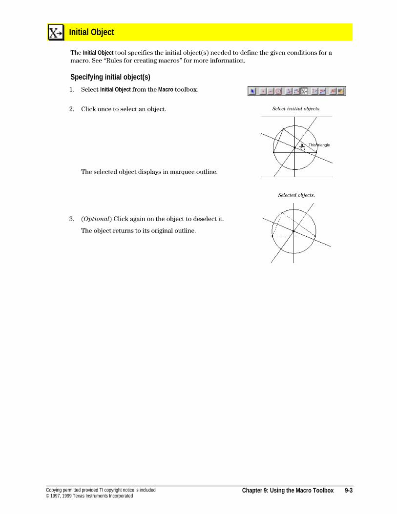
Chapter 9: Using the Macro Toolbox 9-3Copying permitted provided TI copyright notice is included© 1997, 1999 Texas Instruments Incorporated
Initial Object
The Initial Object tool specifies the initial object(s) needed to define the given conditions for amacro. See “Rules for creating macros” for more information.
Specifying initial object(s)
1. Select Initial Object from the Macro toolbox.
2. Click once to select an object.
The selected object displays in marquee outline.
3. (Optional) Click again on the object to deselect it.
The object returns to its original outline.
Select initial objects.
Selected objects.
This triangle
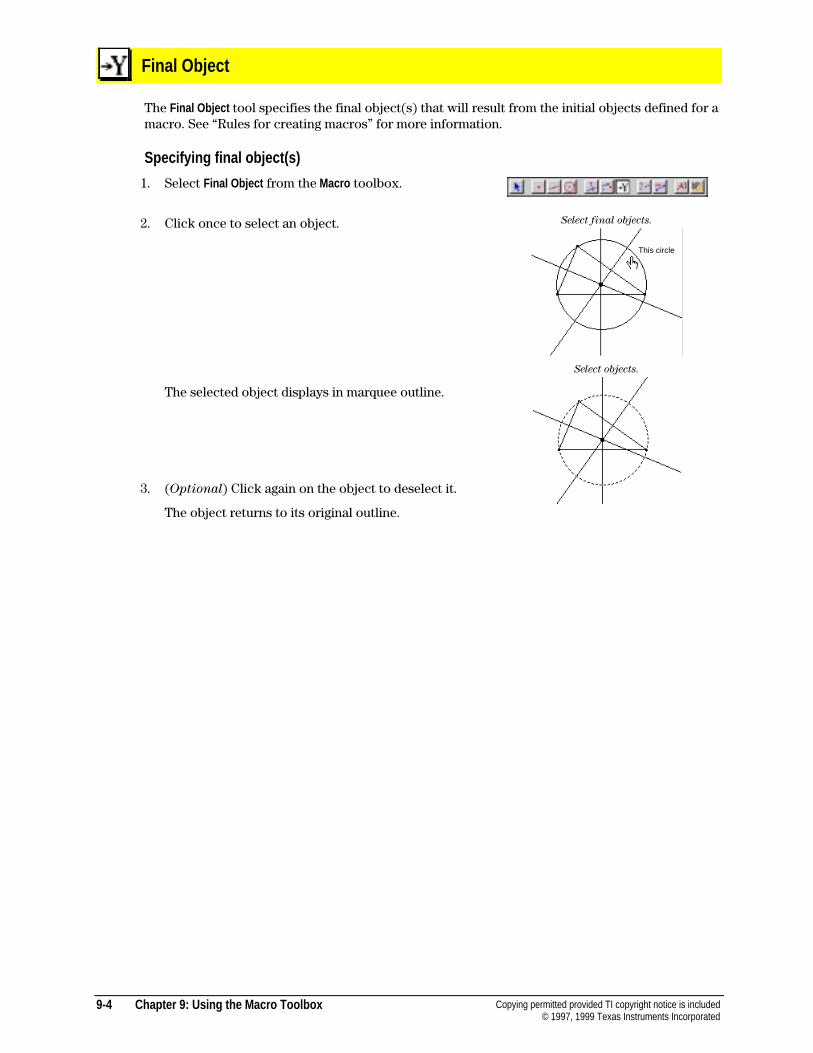
9-4 Chapter 9: Using the Macro Toolbox Copying permitted provided TI copyright notice is included© 1997, 1999 Texas Instruments Incorporated
Final Object
The Final Object tool specifies the final object(s) that will result from the initial objects defined for amacro. See “Rules for creating macros” for more information.
Specifying final object(s)
1. Select Final Object from the Macro toolbox.
2. Click once to select an object.
The selected object displays in marquee outline.
3. (Optional) Click again on the object to deselect it.
The object returns to its original outline.
Select final objects.
Select objects.
This circle
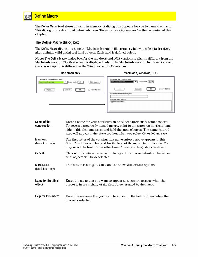
Chapter 9: Using the Macro Toolbox 9-5Copying permitted provided TI copyright notice is included© 1997, 1999 Texas Instruments Incorporated
Define Macro
The Define Macro tool stores a macro in memory. A dialog box appears for you to name the macro.This dialog box is described below. Also see “Rules for creating macros” at the beginning of thischapter.
The Define Macro dialog box
The Define Macro dialog box appears (Macintosh version illustrated) when you select Define Macroafter defining valid initial and final objects. Each field is defined below.
Note: The Define Macro dialog box for the Windows and DOS versions is slightly different from theMacintosh version. The first screen is displayed only in the Macintosh version. In the next screen,the Icon font option is different in the Windows and DOS versions.
Macintosh only Macintosh, Windows, DOS
Name of theconstruction
Enter a name for your construction or select a previously named macro.To access a previously named macro, point to the arrow on the right-handside of this field and press and hold the mouse button. The name enteredhere will appear in the Macro toolbox when you select OK or OK and save .
Icon font:(Macintosh only)
The first letter of the construction name entered above appears in thisfield. This letter will be used for the icon of the macro in the toolbar. Youmay select the font of this letter from Roman, Old English, or Fraktur.
Cancel Click on this button to cancel or disregard the macro definition. Initial andfinal objects will be deselected.
More/Less:(Macintosh only)
This button is a toggle. Click on it to show More or Less options.
Name for first finalobject
Enter the name that you want to appear as a cursor message when thecursor is in the vicinity of the first object created by the macro.
Help for this macro Enter the message that you want to appear in the help window when themacro is selected.

9-6 Chapter 9: Using the Macro Toolbox Copying permitted provided TI copyright notice is included© 1997, 1999 Texas Instruments Incorporated
Define Macro (Continued)
Save to file This button is a toggle. Click on it to change the OK to OK and save , and viceversa.
OK / OK and save Click on OK to save the macro for use in your construction. The macro isnot saved to a separate file but is saved with your construction. Oncesaved, the macro can be used in future Cabri Geometry II sessions.
Click on OK and save to generate a save file dialog that allows you to savethe macro to a file you specify. Macros saved to individual files can berecalled in future constructions by using Open in the File menu to open themacro file.
Specifying a macro
1. Select Define Macro from the Macro toolbox.
2. Enter the requested information into the dialog box tosave your macro.
If you receive a warning message instead of the dialogbox, a problem exists in the definition of initial andfinal objects. Review “Rules for creating macros” atthe beginning of this chapter, and redefine your initialand final objects.
Define Macro dialog box.
Select a new macro.
Select an appropriate object.
Click to apply the macro.
This triangle
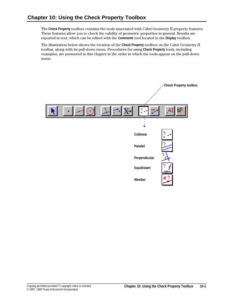
Chapter 10: Using the Check Property Toolbox 10-1Copying permitted provided TI copyright notice is included© 1997, 1999 Texas Instruments Incorporated
Chapter 10: Using the Check Property Toolbox
The Check Property toolbox contains the tools associated with Cabri Geometry II property features.These features allow you to check the validity of geometric properties in general. Results arereported in text, which can be edited with the Comments tool located in the Display toolbox.
The illustration below shows the location of the Check Property toolbox on the Cabri Geometry IItoolbar, along with its pull-down menu. Procedures for using Check Property tools, includingexamples, are presented in this chapter in the order in which the tools appear on the pull-downmenu.
Collinear
Parallel
Perpendicular
Equidistant
Member
Check Property toolbox
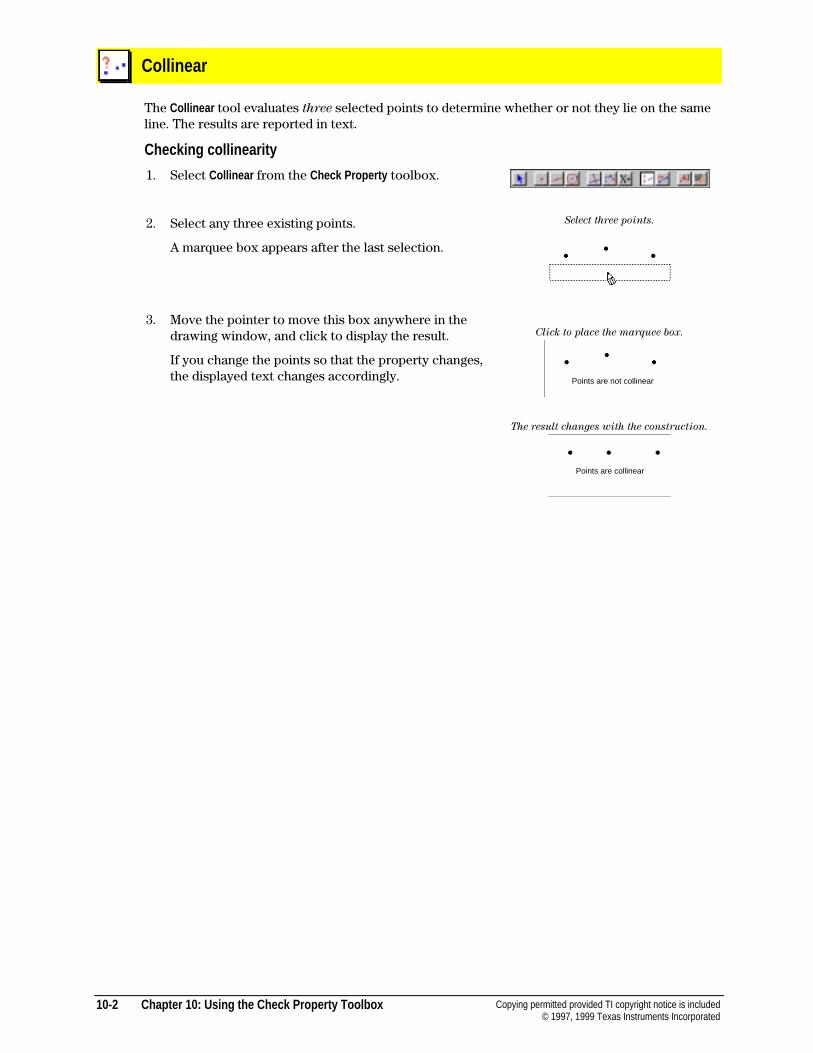
10-2 Chapter 10: Using the Check Property Toolbox Copying permitted provided TI copyright notice is included© 1997, 1999 Texas Instruments Incorporated
Collinear
The Collinear tool evaluates three selected points to determine whether or not they lie on the sameline. The results are reported in text.
Checking collinearity
1. Select Collinear from the Check Property toolbox.
2. Select any three existing points.
A marquee box appears after the last selection.
3. Move the pointer to move this box anywhere in thedrawing window, and click to display the result.
If you change the points so that the property changes,the displayed text changes accordingly.
Select three points.
Click to place the marquee box.
The result changes with the construction.
Points are collinear
Points are not collinear
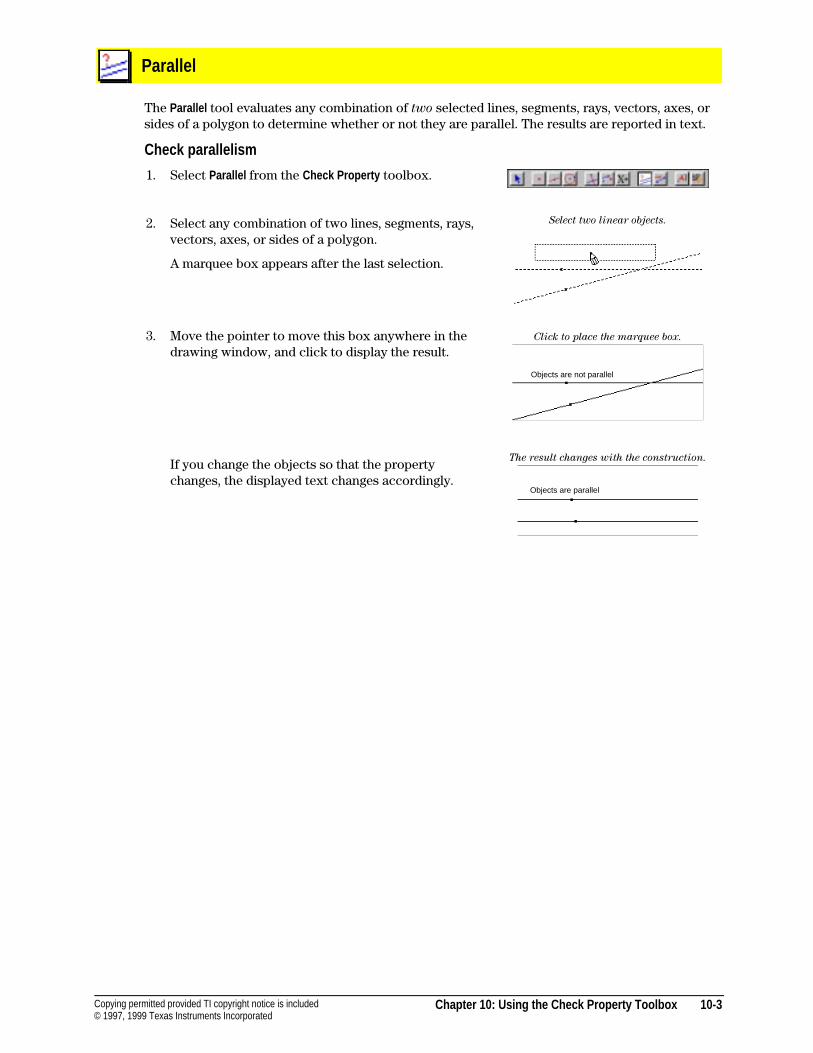
Chapter 10: Using the Check Property Toolbox 10-3Copying permitted provided TI copyright notice is included© 1997, 1999 Texas Instruments Incorporated
Parallel
The Parallel tool evaluates any combination of two selected lines, segments, rays, vectors, axes, orsides of a polygon to determine whether or not they are parallel. The results are reported in text.
Check parallelism
1. Select Parallel from the Check Property toolbox.
2. Select any combination of two lines, segments, rays,vectors, axes, or sides of a polygon.
A marquee box appears after the last selection.
3. Move the pointer to move this box anywhere in thedrawing window, and click to display the result.
If you change the objects so that the propertychanges, the displayed text changes accordingly.
Select two linear objects.
Click to place the marquee box.
The result changes with the construction.
Objects are not parallel
Objects are parallel
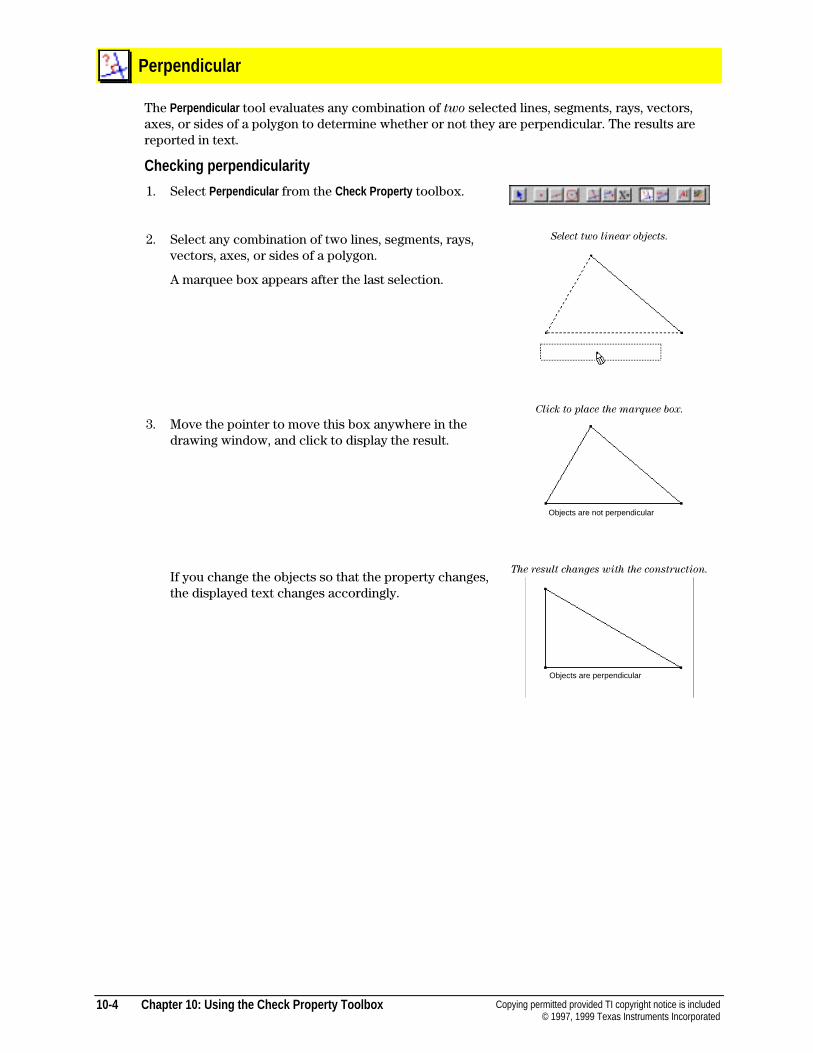
10-4 Chapter 10: Using the Check Property Toolbox Copying permitted provided TI copyright notice is included© 1997, 1999 Texas Instruments Incorporated
Perpendicular
The Perpendicular tool evaluates any combination of two selected lines, segments, rays, vectors,axes, or sides of a polygon to determine whether or not they are perpendicular. The results arereported in text.
Checking perpendicularity
1. Select Perpendicular from the Check Property toolbox.
2. Select any combination of two lines, segments, rays,vectors, axes, or sides of a polygon.
A marquee box appears after the last selection.
3. Move the pointer to move this box anywhere in thedrawing window, and click to display the result.
If you change the objects so that the property changes,the displayed text changes accordingly.
Select two linear objects.
Click to place the marquee box.
The result changes with the construction.
Objects are not perpendicular
Objects are perpendicular
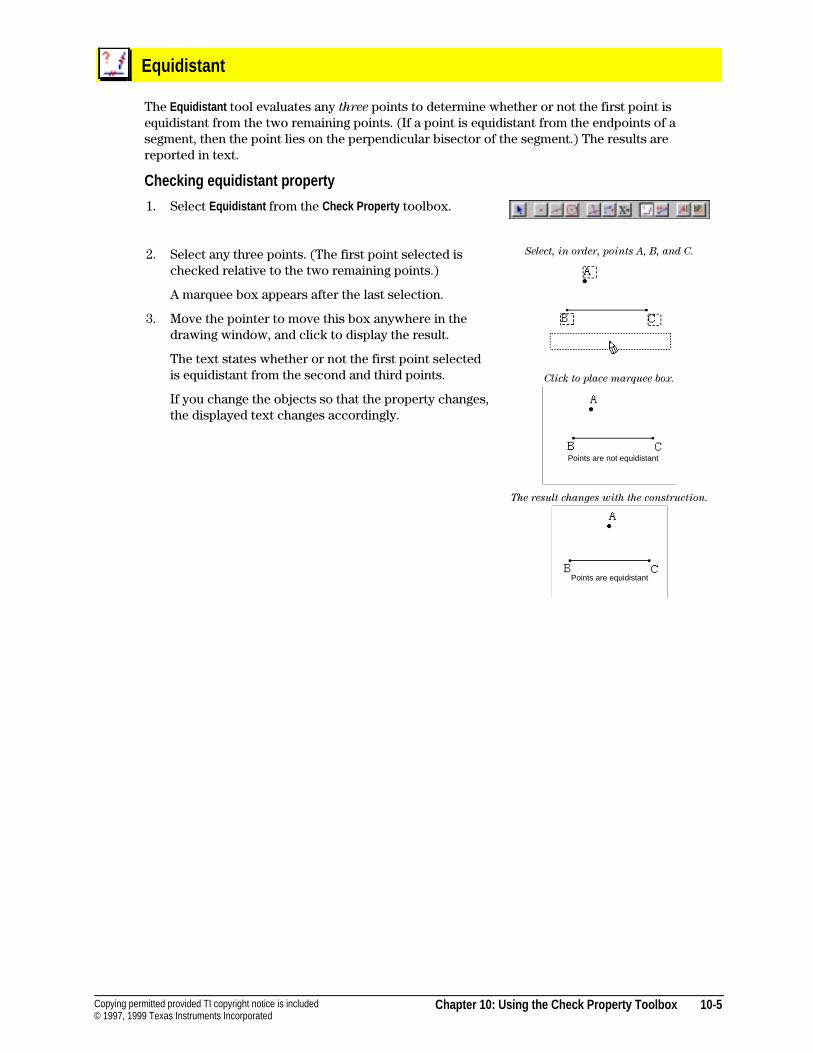
Chapter 10: Using the Check Property Toolbox 10-5Copying permitted provided TI copyright notice is included© 1997, 1999 Texas Instruments Incorporated
Equidistant
The Equidistant tool evaluates any three points to determine whether or not the first point isequidistant from the two remaining points. (If a point is equidistant from the endpoints of asegment, then the point lies on the perpendicular bisector of the segment.) The results arereported in text.
Checking equidistant property
1. Select Equidistant from the Check Property toolbox.
2. Select any three points. (The first point selected ischecked relative to the two remaining points.)
A marquee box appears after the last selection.
3. Move the pointer to move this box anywhere in thedrawing window, and click to display the result.
The text states whether or not the first point selectedis equidistant from the second and third points.
If you change the objects so that the property changes,the displayed text changes accordingly.
Select, in order, points A, B, and C.
Click to place marquee box.
The result changes with the construction.
Points are not equidistant
Points are equidistant
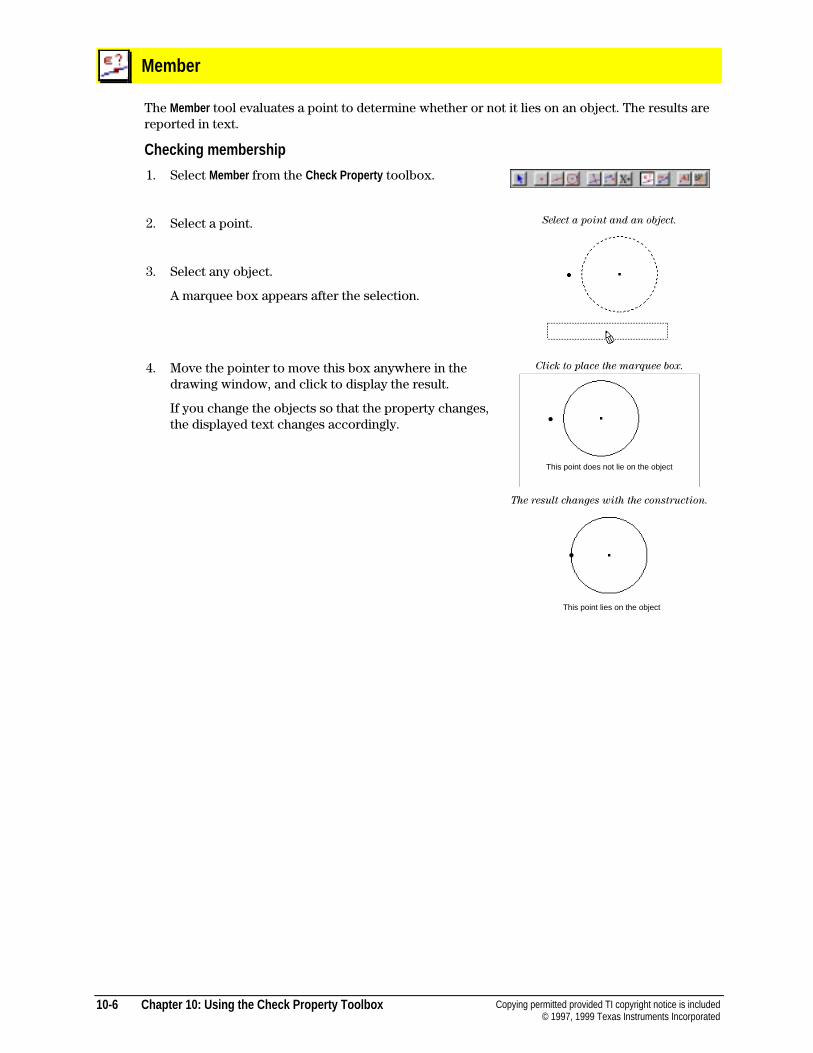
10-6 Chapter 10: Using the Check Property Toolbox Copying permitted provided TI copyright notice is included© 1997, 1999 Texas Instruments Incorporated
Member
The Member tool evaluates a point to determine whether or not it lies on an object. The results arereported in text.
Checking membership
1. Select Member from the Check Property toolbox.
2. Select a point.
3. Select any object.
A marquee box appears after the selection.
4. Move the pointer to move this box anywhere in thedrawing window, and click to display the result.
If you change the objects so that the property changes,the displayed text changes accordingly.
Select a point and an object.
Click to place the marquee box.
The result changes with the construction.
This point lies on the object
This point does not lie on the object
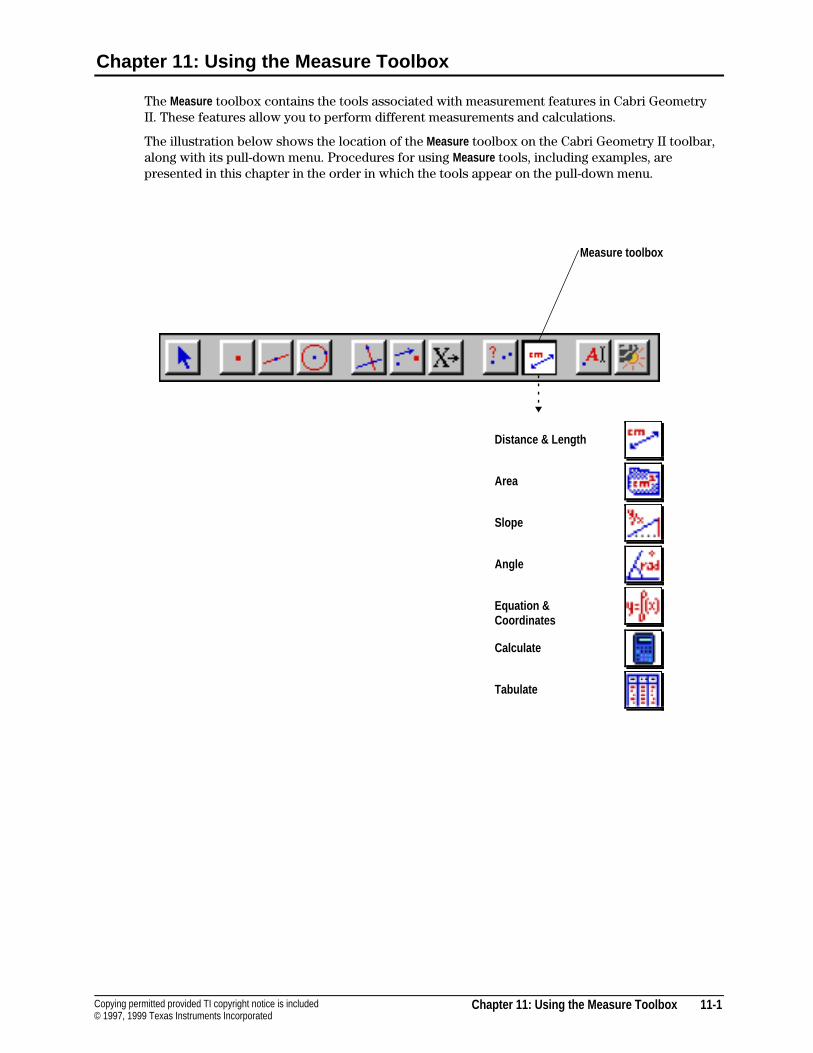
Chapter 11: Using the Measure Toolbox 11-1Copying permitted provided TI copyright notice is included© 1997, 1999 Texas Instruments Incorporated
Chapter 11: Using the Measure Toolbox
The Measure toolbox contains the tools associated with measurement features in Cabri GeometryII. These features allow you to perform different measurements and calculations.
The illustration below shows the location of the Measure toolbox on the Cabri Geometry II toolbar,along with its pull-down menu. Procedures for using Measure tools, including examples, arepresented in this chapter in the order in which the tools appear on the pull-down menu.
Distance & Length
Area
Slope
Angle
Equation &Coordinates
Calculate
Tabulate
Measure toolbox
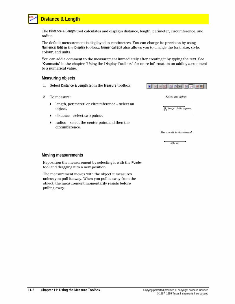
11-2 Chapter 11: Using the Measure Toolbox Copying permitted provided TI copyright notice is included© 1997, 1999 Texas Instruments Incorporated
Distance & Length
The Distance & Length tool calculates and displays distance, length, perimeter, circumference, andradius.
The default measurement is displayed in centimetres. You can change its precision by usingNumerical Edit in the Display toolbox. Numerical Edit also allows you to change the font, size, style,colour, and units.
You can add a comment to the measurement immediately after creating it by typing the text. See“Comments” in the chapter “Using the Display Toolbox” for more information on adding a commentto a numerical value.
Measuring objects
1. Select Distance & Length from the Measure toolbox.
2. To measure:
4 length, perimeter, or circumference – select anobject.
4 distance – select two points.
4 radius – select the center point and then thecircumference.
Select an object.
The result is displayed.
Moving measurements
Reposition the measurement by selecting it with the Pointertool and dragging it to a new position.
The measurement moves with the object it measuresunless you pull it away. When you pull it away from theobject, the measurement momentarily resists beforepulling away.
Length of this segment
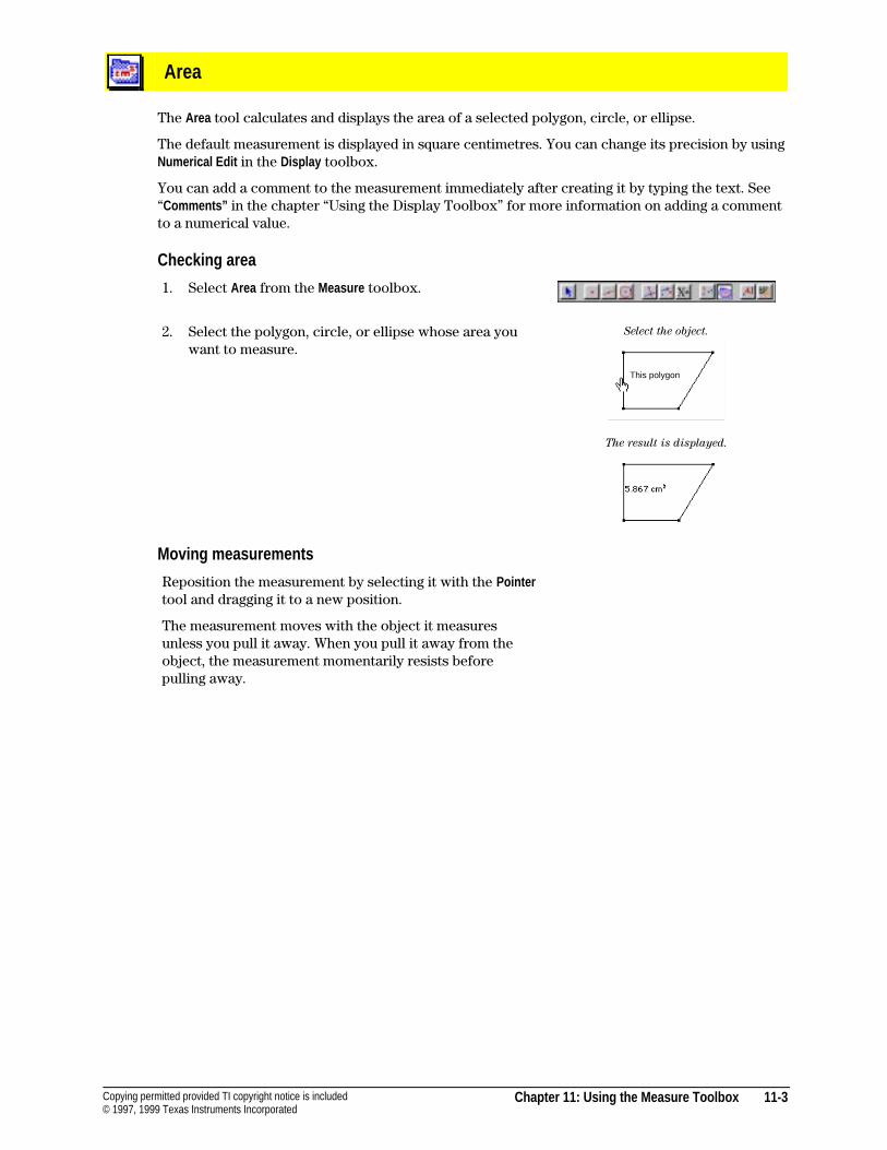
Chapter 11: Using the Measure Toolbox 11-3Copying permitted provided TI copyright notice is included© 1997, 1999 Texas Instruments Incorporated
Area
The Area tool calculates and displays the area of a selected polygon, circle, or ellipse.
The default measurement is displayed in square centimetres. You can change its precision by usingNumerical Edit in the Display toolbox.
You can add a comment to the measurement immediately after creating it by typing the text. See“Comments” in the chapter “Using the Display Toolbox” for more information on adding a commentto a numerical value.
Checking area
1. Select Area from the Measure toolbox.
2. Select the polygon, circle, or ellipse whose area youwant to measure.
Select the object.
The result is displayed.
Moving measurements
Reposition the measurement by selecting it with the Pointertool and dragging it to a new position.
The measurement moves with the object it measuresunless you pull it away. When you pull it away from theobject, the measurement momentarily resists beforepulling away.
This polygon
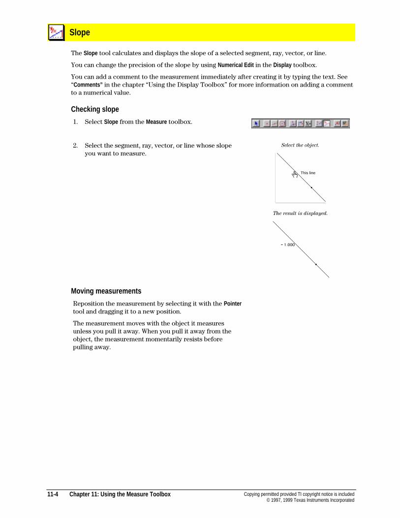
11-4 Chapter 11: Using the Measure Toolbox Copying permitted provided TI copyright notice is included© 1997, 1999 Texas Instruments Incorporated
Slope
The Slope tool calculates and displays the slope of a selected segment, ray, vector, or line.
You can change the precision of the slope by using Numerical Edit in the Display toolbox.
You can add a comment to the measurement immediately after creating it by typing the text. See“Comments” in the chapter “Using the Display Toolbox” for more information on adding a commentto a numerical value.
Checking slope
1. Select Slope from the Measure toolbox.
2. Select the segment, ray, vector, or line whose slopeyou want to measure.
Select the object.
The result is displayed.
Moving measurements
Reposition the measurement by selecting it with the Pointertool and dragging it to a new position.
The measurement moves with the object it measuresunless you pull it away. When you pull it away from theobject, the measurement momentarily resists beforepulling away.
This line
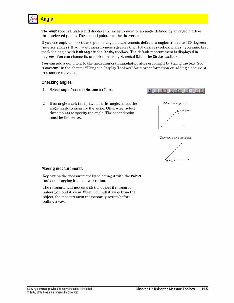
Chapter 11: Using the Measure Toolbox 11-5Copying permitted provided TI copyright notice is included© 1997, 1999 Texas Instruments Incorporated
Angle
The Angle tool calculates and displays the measurement of an angle defined by an angle mark orthree selected points. The second point must be the vertex.
If you use Angle to select three points, angle measurements default to angles from 0 to 180 degrees(interior angles). If you want measurements greater than 180 degrees (reflex angles), you must firstmark the angle with Mark Angle in the Display toolbox. The default measurement is displayed indegrees. You can change its precision by using Numerical Edit in the Display toolbox.
You can add a comment to the measurement immediately after creating it by typing the text. See“Comments” in the chapter “Using the Display Toolbox” for more information on adding a commentto a numerical value.
Checking angles
1. Select Angle from the Measure toolbox.
2. If an angle mark is displayed on the angle, select theangle mark to measure the angle. Otherwise, selectthree points to specify the angle. The second pointmust be the vertex.
Select three points.
The result is displayed.
Moving measurements
Reposition the measurement by selecting it with the Pointertool and dragging it to a new position.
The measurement moves with the object it measuresunless you pull it away. When you pull it away from theobject, the measurement momentarily resists beforepulling away.
This point
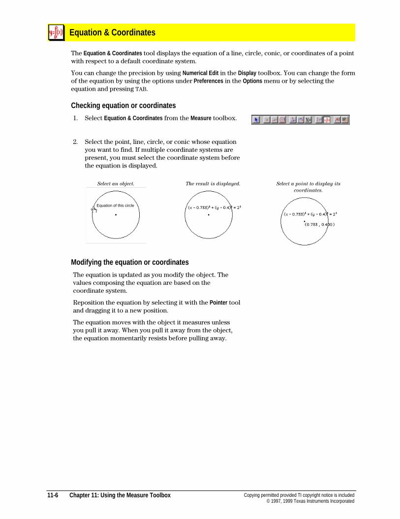
11-6 Chapter 11: Using the Measure Toolbox Copying permitted provided TI copyright notice is included© 1997, 1999 Texas Instruments Incorporated
Equation & Coordinates
The Equation & Coordinates tool displays the equation of a line, circle, conic, or coordinates of a pointwith respect to a default coordinate system.
You can change the precision by using Numerical Edit in the Display toolbox. You can change the formof the equation by using the options under Preferences in the Options menu or by selecting theequation and pressing TAB.
Checking equation or coordinates
1. Select Equation & Coordinates from the Measure toolbox.
2. Select the point, line, circle, or conic whose equationyou want to find. If multiple coordinate systems arepresent, you must select the coordinate system beforethe equation is displayed.
Select an object. The result is displayed. Select a point to display its
coordinates.
Modifying the equation or coordinates
The equation is updated as you modify the object. Thevalues composing the equation are based on thecoordinate system.
Reposition the equation by selecting it with the Pointer tooland dragging it to a new position.
The equation moves with the object it measures unlessyou pull it away. When you pull it away from the object,the equation momentarily resists before pulling away.
Equation of this circle
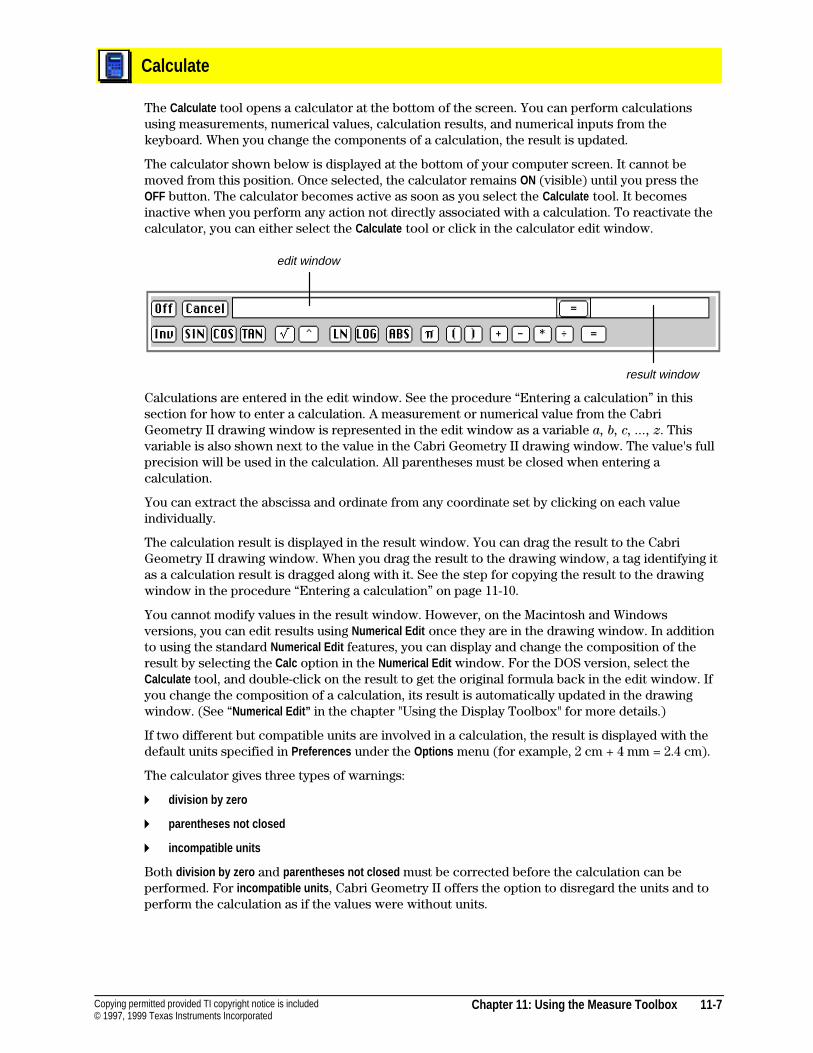
Chapter 11: Using the Measure Toolbox 11-7Copying permitted provided TI copyright notice is included© 1997, 1999 Texas Instruments Incorporated
Calculate
The Calculate tool opens a calculator at the bottom of the screen. You can perform calculationsusing measurements, numerical values, calculation results, and numerical inputs from thekeyboard. When you change the components of a calculation, the result is updated.
The calculator shown below is displayed at the bottom of your computer screen. It cannot bemoved from this position. Once selected, the calculator remains ON (visible) until you press theOFF button. The calculator becomes active as soon as you select the Calculate tool. It becomesinactive when you perform any action not directly associated with a calculation. To reactivate thecalculator, you can either select the Calculate tool or click in the calculator edit window.
edit window
result window
Calculations are entered in the edit window. See the procedure “Entering a calculation” in thissection for how to enter a calculation. A measurement or numerical value from the CabriGeometry II drawing window is represented in the edit window as a variable a, b, c, ..., z. Thisvariable is also shown next to the value in the Cabri Geometry II drawing window. The value's fullprecision will be used in the calculation. All parentheses must be closed when entering acalculation.
You can extract the abscissa and ordinate from any coordinate set by clicking on each valueindividually.
The calculation result is displayed in the result window. You can drag the result to the CabriGeometry II drawing window. When you drag the result to the drawing window, a tag identifying itas a calculation result is dragged along with it. See the step for copying the result to the drawingwindow in the procedure “Entering a calculation” on page 11-10.
You cannot modify values in the result window. However, on the Macintosh and Windowsversions, you can edit results using Numerical Edit once they are in the drawing window. In additionto using the standard Numerical Edit features, you can display and change the composition of theresult by selecting the Calc option in the Numerical Edit window. For the DOS version, select theCalculate tool, and double-click on the result to get the original formula back in the edit window. Ifyou change the composition of a calculation, its result is automatically updated in the drawingwindow. (See “Numerical Edit” in the chapter "Using the Display Toolbox" for more details.)
If two different but compatible units are involved in a calculation, the result is displayed with thedefault units specified in Preferences under the Options menu (for example, 2 cm + 4 mm = 2.4 cm).
The calculator gives three types of warnings:
4 division by zero
4 parentheses not closed
4 incompatible units
Both division by zero and parentheses not closed must be corrected before the calculation can beperformed. For incompatible units , Cabri Geometry II offers the option to disregard the units and toperform the calculation as if the values were without units.
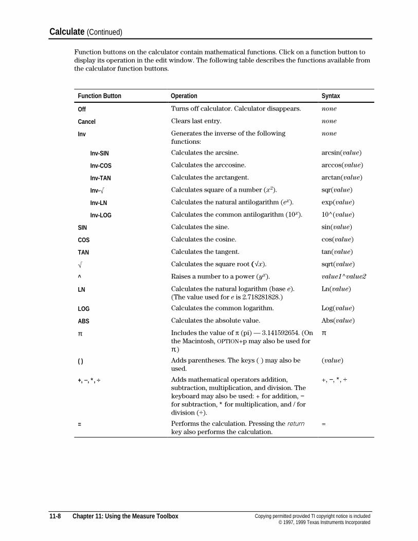
11-8 Chapter 11: Using the Measure Toolbox Copying permitted provided TI copyright notice is included© 1997, 1999 Texas Instruments Incorporated
Calculate (Continued)
Function buttons on the calculator contain mathematical functions. Click on a function button todisplay its operation in the edit window. The following table describes the functions available fromthe calculator function buttons.
Function Button Operation Syntax
Off Turns off calculator. Calculator disappears. none
Cancel Clears last entry. none
Inv Generates the inverse of the followingfunctions:
none
Inv-SIN Calculates the arcsine. arcsin(value)
Inv-COS Calculates the arccosine. arccos(value)
Inv-TAN Calculates the arctangent. arctan(value)
Inv-‡ Calculates square of a number (x2). sqr(value)
Inv-LN Calculates the natural antilogarithm (ex). exp(value)
Inv-LOG Calculates the common antilogarithm (10x). 10^(value)
SIN Calculates the sine. sin(value)
COS Calculates the cosine. cos(value)
TAN Calculates the tangent. tan(value)
‡ Calculates the square root (√x). sqrt(value)
^ Raises a number to a power (yx). value1^value2
LN Calculates the natural logarithm (base e).(The value used for e is 2.718281828.)
Ln(value)
LOG Calculates the common logarithm. Log(value)
ABS Calculates the absolute value. Abs(value)
π Includes the value of p (pi) — 3.141592654. (Onthe Macintosh, OPTION+p may also be used forπ.)
π
( ) Adds parentheses. The keys ( ) may also beused.
(value)
+, −, ∗, ÷ Adds mathematical operators addition,subtraction, multiplication, and division. Thekeyboard may also be used: + for addition, −for subtraction, ∗ for multiplication, and / fordivision (÷).
+, −, ∗, ÷
= Performs the calculation. Pressing the returnkey also performs the calculation.
=
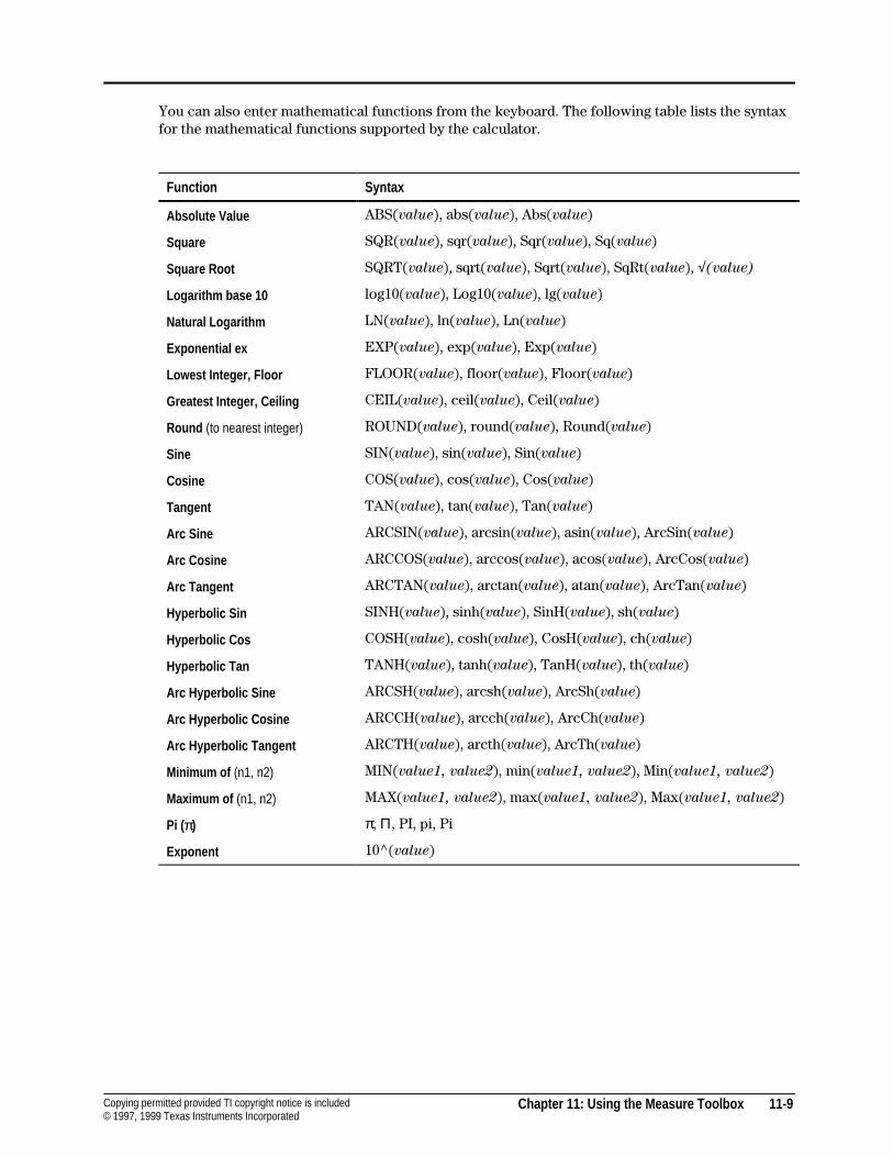
Chapter 11: Using the Measure Toolbox 11-9Copying permitted provided TI copyright notice is included© 1997, 1999 Texas Instruments Incorporated
You can also enter mathematical functions from the keyboard. The following table lists the syntaxfor the mathematical functions supported by the calculator.
Function Syntax
Absolute Value ABS(value), abs(value), Abs(value)
Square SQR(value), sqr(value), Sqr(value), Sq(value)
Square Root SQRT(value), sqrt(value), Sqrt(value), SqRt(value), √(value)
Logarithm base 10 log10(value), Log10(value), lg(value)
Natural Logarithm LN(value), ln(value), Ln(value)
Exponential ex EXP(value), exp(value), Exp(value)
Lowest Integer, Floor FLOOR(value), floor(value), Floor(value)
Greatest Integer, Ceiling CEIL(value), ceil(value), Ceil(value)
Round (to nearest integer) ROUND(value), round(value), Round(value)
Sine SIN(value), sin(value), Sin(value)
Cosine COS(value), cos(value), Cos(value)
Tangent TAN(value), tan(value), Tan(value)
Arc Sine ARCSIN(value), arcsin(value), asin(value), ArcSin(value)
Arc Cosine ARCCOS(value), arccos(value), acos(value), ArcCos(value)
Arc Tangent ARCTAN(value), arctan(value), atan(value), ArcTan(value)
Hyperbolic Sin SINH(value), sinh(value), SinH(value), sh(value)
Hyperbolic Cos COSH(value), cosh(value), CosH(value), ch(value)
Hyperbolic Tan TANH(value), tanh(value), TanH(value), th(value)
Arc Hyperbolic Sine ARCSH(value), arcsh(value), ArcSh(value)
Arc Hyperbolic Cosine ARCCH(value), arcch(value), ArcCh(value)
Arc Hyperbolic Tangent ARCTH(value), arcth(value), ArcTh(value)
Minimum of (n1, n2) MIN(value1, value2), min(value1, value2), Min(value1, value2)
Maximum of (n1, n2) MAX(value1, value2), max(value1, value2), Max(value1, value2)
Pi (π) π, Π, PI, pi, Pi
Exponent 10^(value)
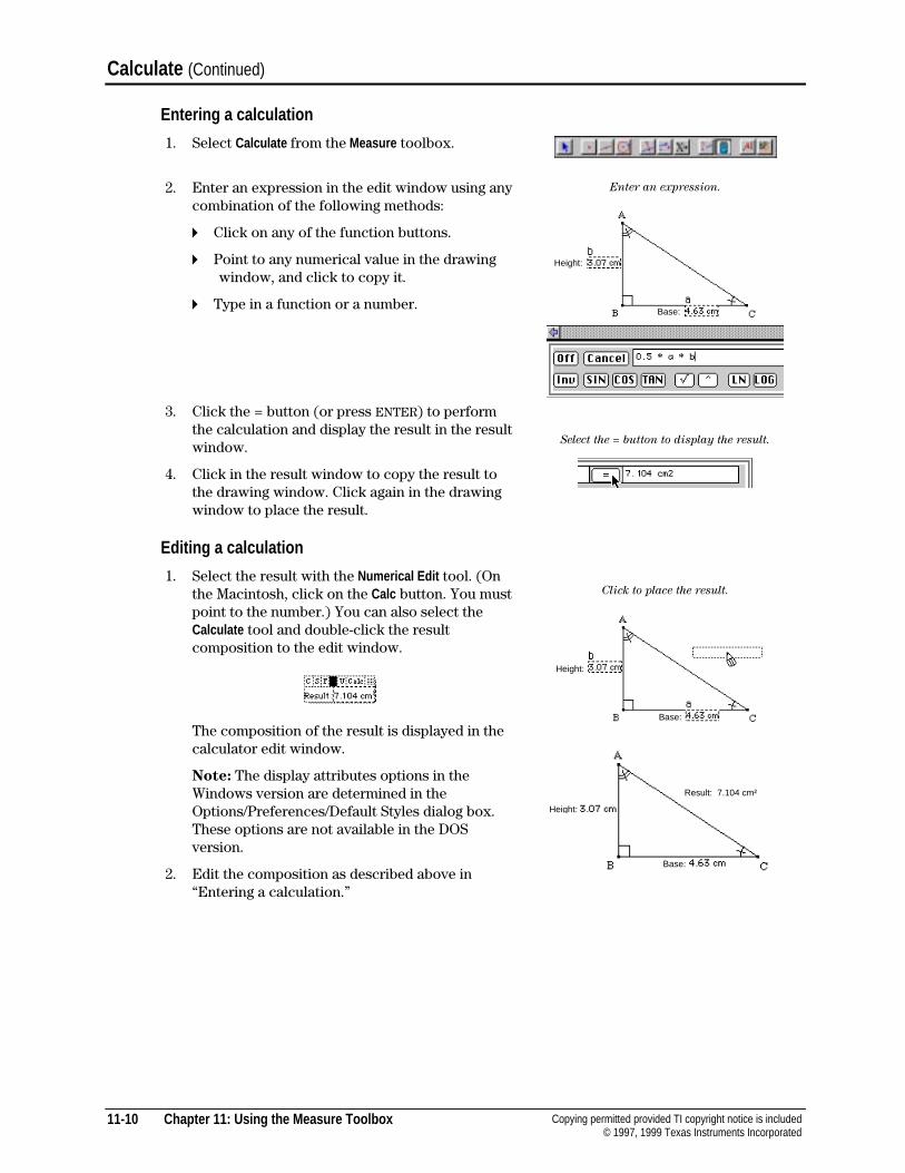
11-10 Chapter 11: Using the Measure Toolbox Copying permitted provided TI copyright notice is included© 1997, 1999 Texas Instruments Incorporated
Calculate (Continued)
Entering a calculation
1. Select Calculate from the Measure toolbox.
2. Enter an expression in the edit window using anycombination of the following methods:
4 Click on any of the function buttons.
4 Point to any numerical value in the drawing window, and click to copy it.
4 Type in a function or a number.
3. Click the = button (or press ENTER) to performthe calculation and display the result in the resultwindow.
4. Click in the result window to copy the result tothe drawing window. Click again in the drawingwindow to place the result.
Enter an expression.
Select the = button to display the result.
Editing a calculation
1. Select the result with the Numerical Edit tool. (Onthe Macintosh, click on the Calc button. You mustpoint to the number.) You can also select theCalculate tool and double-click the resultcomposition to the edit window.
The composition of the result is displayed in thecalculator edit window.
Note: The display attributes options in theWindows version are determined in theOptions/Preferences/Default Styles dialog box.These options are not available in the DOSversion.
2. Edit the composition as described above in“Entering a calculation.”
Click to place the result.
Height:
Base:
Height:
Base:
Height:
Base:
Result: 7.104 cm²
Chapter 11: Using the Measure Toolbox 11-11Copying permitted provided TI copyright notice is included© 1997, 1999 Texas Instruments Incorporated
Tabulate
The Tabulate tool collects selected measurements, calculations, and numerical values into a singledata table. You must define the table before values can be entered.
When you select values for tabulation, they are entered into the next available column of the table.If the value has a label comment, it is copied into the first row of the column and the value iscopied into the next available row. If the value does not have a label comment, the first row will beempty for that column. Comments that you later add to tabulation values are copied into the firstrow in that value’s column. See “Comments” in the chapter “Using the Display Toolbox” forinstructions on adding a comment to a numerical value.
The values in a column are not displayed unless the full width of the column is visible. Each row ofthe table is numbered sequentially in the first column on the left. You can enter single values intothe table when at least one object changes and you press the TAB key.
You can collect data automatically by selecting the table, and then using Animation . Data is stored inthe table for each of the defined tabulation values at a rate relative to the animation.
You can delete columns or rows, and change column width (see page 11-13). The maximumnumber of rows is 999. The number of columns is limited by memory.
You can make only one table for each Cabri Geometry II drawing. You can copy the values in atable to another program (such as a spreadsheet program). First, select the table with the Pointertool, and use Copy from the Edit menu. Then go to the target program, and paste the data.
Note: The example tables shown on the following pages are for the Macintosh version using theChicago font. The display attributes options are not available for the Windows and DOS versions;therefore, the fonts displayed on your screen will be different.

11-12 Chapter 11: Using the Measure Toolbox Copying permitted provided TI copyright notice is included© 1997, 1999 Texas Instruments Incorporated
Tabulate (Continued)
Using Tabulate
1. Select Tabulate from the Measure menu.
2. Define the table by dragging the marquee rectangle tosize the table. You can resize the table by dragging thelower right corner.
3. Point to a numerical value, and click to enter it intothe table.
4. Press TAB to record new values.
Note: At least one value must change before a newrow is entered.
To tabulate values automatically, first select the table,and then animate the construction using Animation orMultiple Animation (in the Display toolbox).
When selected, the table displays with a marqueerectangle around it.
Drag rectangle to size the table.
Click on each value to be tabulated.
Press the TAB key to tabulate entries.
Adding values
1. Select Tabulate , and then point to the value and click.
The new value is added in the next available columnand row. Blank cells in the new column will be filledwith a hyphen (-).
2. Press TAB to record new values.
Area 1.2601 cm2
Radius 0.63 cmThis number
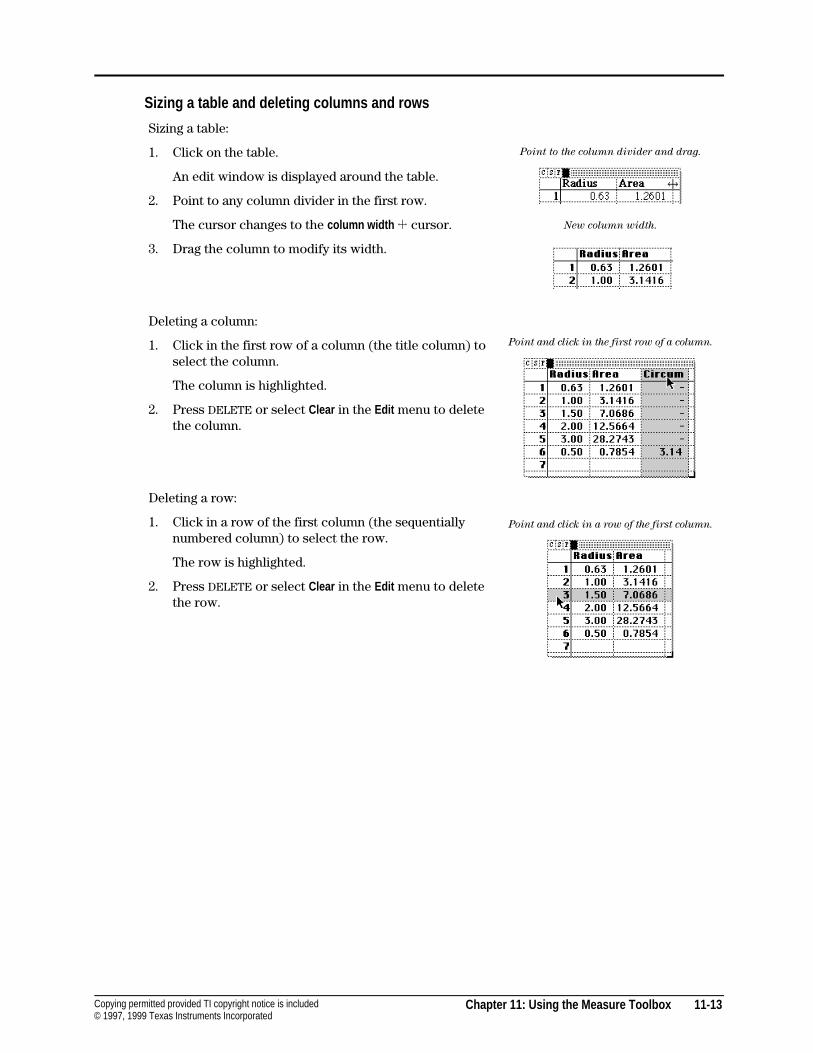
Chapter 11: Using the Measure Toolbox 11-13Copying permitted provided TI copyright notice is included© 1997, 1999 Texas Instruments Incorporated
Sizing a table and deleting columns and rows
Sizing a table:
1. Click on the table.
An edit window is displayed around the table.
2. Point to any column divider in the first row.
The cursor changes to the column width 3 cursor.
3. Drag the column to modify its width.
Deleting a column:
1. Click in the first row of a column (the title column) toselect the column.
The column is highlighted.
2. Press DELETE or select Clear in the Edit menu to deletethe column.
Deleting a row:
1. Click in a row of the first column (the sequentiallynumbered column) to select the row.
The row is highlighted.
2. Press DELETE or select Clear in the Edit menu to deletethe row.
Point to the column divider and drag.
New column width.
Point and click in the first row of a column.
Point and click in a row of the first column.
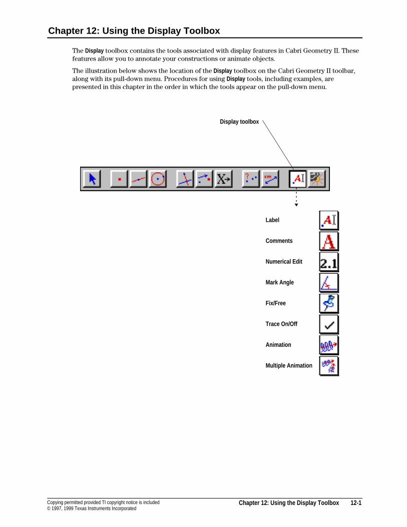
Chapter 12: Using the Display Toolbox 12-1Copying permitted provided TI copyright notice is included© 1997, 1999 Texas Instruments Incorporated
Chapter 12: Using the Display Toolbox
The Display toolbox contains the tools associated with display features in Cabri Geometry II. Thesefeatures allow you to annotate your constructions or animate objects.
The illustration below shows the location of the Display toolbox on the Cabri Geometry II toolbar,along with its pull-down menu. Procedures for using Display tools, including examples, arepresented in this chapter in the order in which the tools appear on the pull-down menu.
Label
Comments
Numerical Edit
Mark Angle
Fix/Free
Trace On/Off
Animation
Multiple Animation
Display toolbox
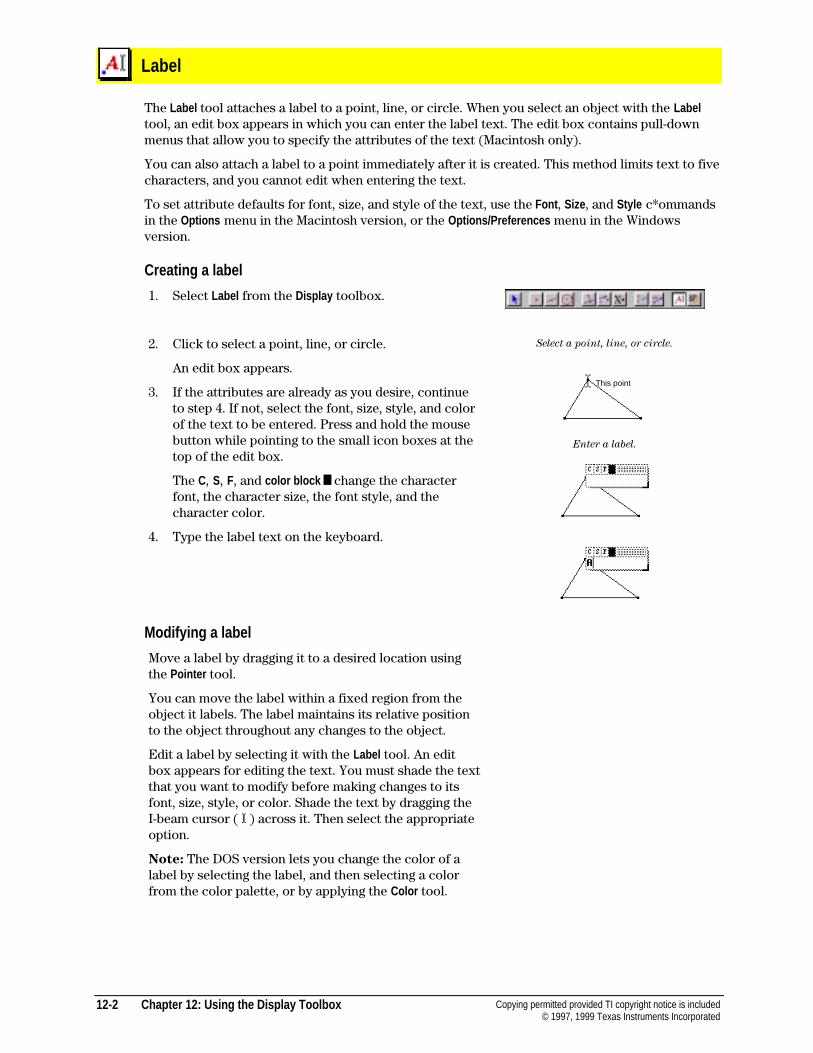
12-2 Chapter 12: Using the Display Toolbox Copying permitted provided TI copyright notice is included© 1997, 1999 Texas Instruments Incorporated
Label
The Label tool attaches a label to a point, line, or circle. When you select an object with the Labeltool, an edit box appears in which you can enter the label text. The edit box contains pull-downmenus that allow you to specify the attributes of the text (Macintosh only).
You can also attach a label to a point immediately after it is created. This method limits text to fivecharacters, and you cannot edit when entering the text.
To set attribute defaults for font, size, and style of the text, use the Font , Size, and Style c*ommandsin the Options menu in the Macintosh version, or the Options/Preferences menu in the Windowsversion.
Creating a label
1. Select Label from the Display toolbox.
2. Click to select a point, line, or circle.
An edit box appears.
3. If the attributes are already as you desire, continueto step 4. If not, select the font, size, style, and colorof the text to be entered. Press and hold the mousebutton while pointing to the small icon boxes at thetop of the edit box.
The C, S, F, and color block ²² change the characterfont, the character size, the font style, and thecharacter color.
4. Type the label text on the keyboard.
Select a point, line, or circle.
Enter a label.
Modifying a label
Move a label by dragging it to a desired location usingthe Pointer tool.
You can move the label within a fixed region from theobject it labels. The label maintains its relative positionto the object throughout any changes to the object.
Edit a label by selecting it with the Label tool. An editbox appears for editing the text. You must shade the textthat you want to modify before making changes to itsfont, size, style, or color. Shade the text by dragging theI-beam cursor ( I ) across it. Then select the appropriateoption.
Note: The DOS version lets you change the color of alabel by selecting the label, and then selecting a colorfrom the color palette, or by applying the Color tool.
This point
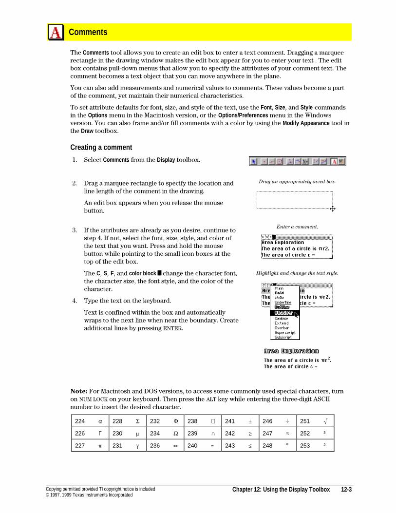
Chapter 12: Using the Display Toolbox 12-3Copying permitted provided TI copyright notice is included© 1997, 1999 Texas Instruments Incorporated
Comments
The Comments tool allows you to create an edit box to enter a text comment. Dragging a marqueerectangle in the drawing window makes the edit box appear for you to enter your text . The editbox contains pull-down menus that allow you to specify the attributes of your comment text. Thecomment becomes a text object that you can move anywhere in the plane.
You can also add measurements and numerical values to comments. These values become a partof the comment, yet maintain their numerical characteristics.
To set attribute defaults for font, size, and style of the text, use the Font , Size, and Style commandsin the Options menu in the Macintosh version, or the Options/Preferences menu in the Windowsversion. You can also frame and/or fill comments with a color by using the Modify Appearance tool inthe Draw toolbox.
Creating a comment
1. Select Comments from the Display toolbox.
2. Drag a marquee rectangle to specify the location andline length of the comment in the drawing.
An edit box appears when you release the mousebutton.
3. If the attributes are already as you desire, continue tostep 4. If not, select the font, size, style, and color ofthe text that you want. Press and hold the mousebutton while pointing to the small icon boxes at thetop of the edit box.
The C, S, F, and color block ²² change the character font,the character size, the font style, and the color of thecharacter.
4. Type the text on the keyboard.
Text is confined within the box and automaticallywraps to the next line when near the boundary. Createadditional lines by pressing ENTER.
Drag an appropriately sized box.
Enter a comment.
Highlight and change the text style.
Note: For Macintosh and DOS versions, to access some commonly used special characters, turnon NUM LOCK on your keyboard. Then press the ALT key while entering the three-digit ASCIInumber to insert the desired character.
224 a 228 G 232 Φ 238 ∈ 241 „ 246 ÷ 251 ‡
226 Γ 230 m 234 J 239 ∩ 242 ‚ 247 ≈ 252 ³
227 p 231 g 236 ˆ 240 � 243 � 248 ¡ 253 ²
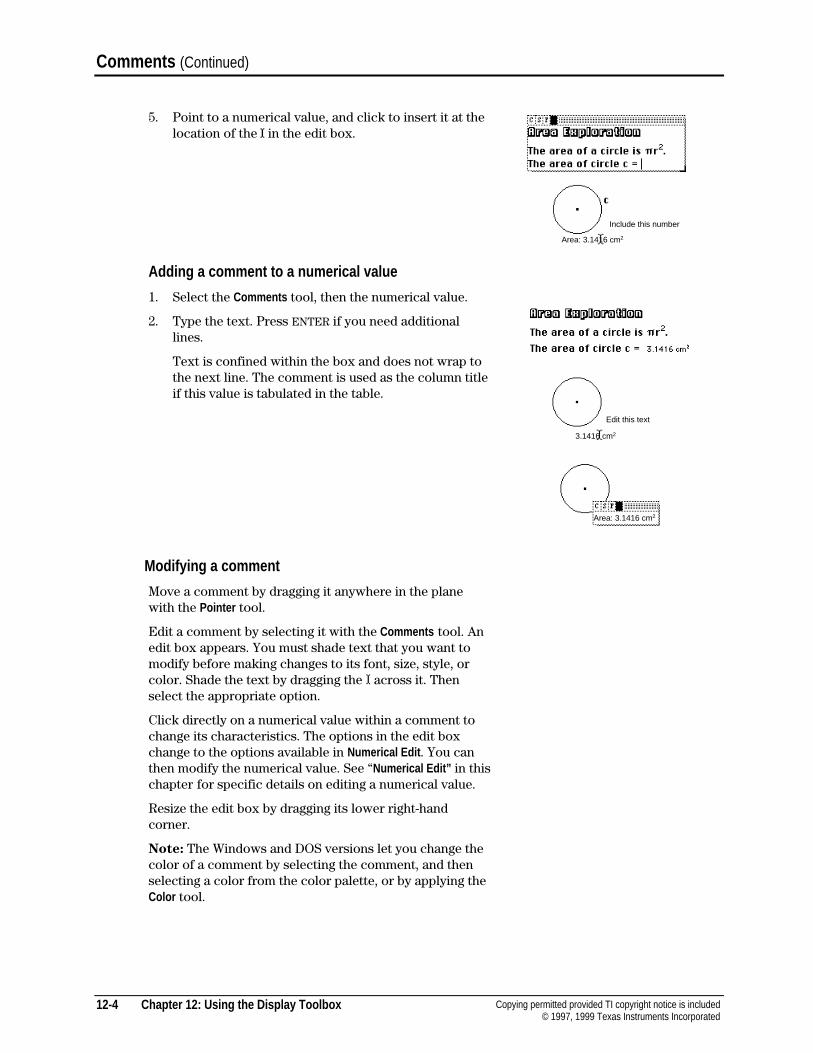
12-4 Chapter 12: Using the Display Toolbox Copying permitted provided TI copyright notice is included© 1997, 1999 Texas Instruments Incorporated
Comments (Continued)
5. Point to a numerical value, and click to insert it at thelocation of the II in the edit box.
Adding a comment to a numerical value
1. Select the Comments tool, then the numerical value.
2. Type the text. Press ENTER if you need additionallines.
Text is confined within the box and does not wrap tothe next line. The comment is used as the column titleif this value is tabulated in the table.
Modifying a comment
Move a comment by dragging it anywhere in the planewith the Pointer tool.
Edit a comment by selecting it with the Comments tool. Anedit box appears. You must shade text that you want tomodify before making changes to its font, size, style, orcolor. Shade the text by dragging the I across it. Thenselect the appropriate option.
Click directly on a numerical value within a comment tochange its characteristics. The options in the edit boxchange to the options available in Numerical Edit . You canthen modify the numerical value. See “Numerical Edit” in thischapter for specific details on editing a numerical value.
Resize the edit box by dragging its lower right-handcorner.
Note: The Windows and DOS versions let you change thecolor of a comment by selecting the comment, and thenselecting a color from the color palette, or by applying theColor tool.
Include this number
Area: 3.1416 cm2
3.1416 cm2
Area: 3.1416 cm2
Edit this text
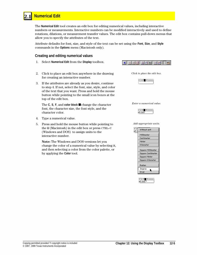
Chapter 12: Using the Display Toolbox 12-5Copying permitted provided TI copyright notice is included© 1997, 1999 Texas Instruments Incorporated
Numerical Edit
The Numerical Edit tool creates an edit box for editing numerical values, including interactivenumbers or measurements. Interactive numbers can be modified interactively and used to definerotations, dilations, or measurement transfer values. The edit box contains pull-down menus thatallow you to specify the attributes of the text.
Attribute defaults for font, size, and style of the text can be set using the Font , Size, and Stylecommands in the Options menu (Macintosh only).
Creating and editing numerical values
1. Select Numerical Edit from the Display toolbox.
2. Click to place an edit box anywhere in the drawingfor creating an interactive number.
3. If the attributes are already as you desire, continueto step 4. If not, select the font, size, style, and colorof the text that you want. Press and hold the mousebutton while pointing to the small icon boxes at thetop of the edit box.
The C, S, F, and color block ■ change the characterfont, the character size, the font style, and thecharacter color.
4. Type a numerical value.
5. Press and hold the mouse button while pointing tothe U (Macintosh) in the edit box or press CTRL+U(Windows and DOS) to assign units to theinteractive number.
Note: The Windows and DOS versions let youchange the color of a numerical value by selecting it,and then selecting a color from the color palette, orby applying the Color tool.
Click to place the edit box.
Enter a numerical value.
Add appropriate units.
12-6 Chapter 12: Using the Display Toolbox Copying permitted provided TI copyright notice is included© 1997, 1999 Texas Instruments Incorporated
Numerical Edit (Continued)
Modifying a numerical value
Move the numerical value by dragging it anywhere in theplane with the Pointer tool.
You can modify numerical values interactively when theedit box is active. Using the arrow keys, place the I to theright of the digit you want to change. Use the up -arrow keyto increase the digit by 1. Use the down- arrow key todecrease the digit by 1.
You can change these values automatically withanimation. Using the Animation tool, select the number asyou would select any object. The digit increases ordecreases relative to the cursor position and to thedirection indicated by the Animation tool.
You can change the units of a numerical value or itsdisplayed precision. Using the Numerical Edit tool, select thenumerical value. Select the U (Macintosh) in the edit boxor press CTRL+U (Windows and DOS), and assign a unit toany number or change to the desired units.
Cabri Geometry II performs unit conversions based on thenumber's current unit assignment. Press the + key toincrease the precision displayed by 1 digit. Press the − keyto decrease the precision displayed by 1 digit.
Change the character attributes of a numerical value byselecting it using the Numerical Edit tool. An edit boxappears for editing the number. You must shade the textthat you want to modify before making changes to its font,size, style, or color. Shade the text by dragging the I acrossit. Then select the appropriate option from the icons in theedit box.
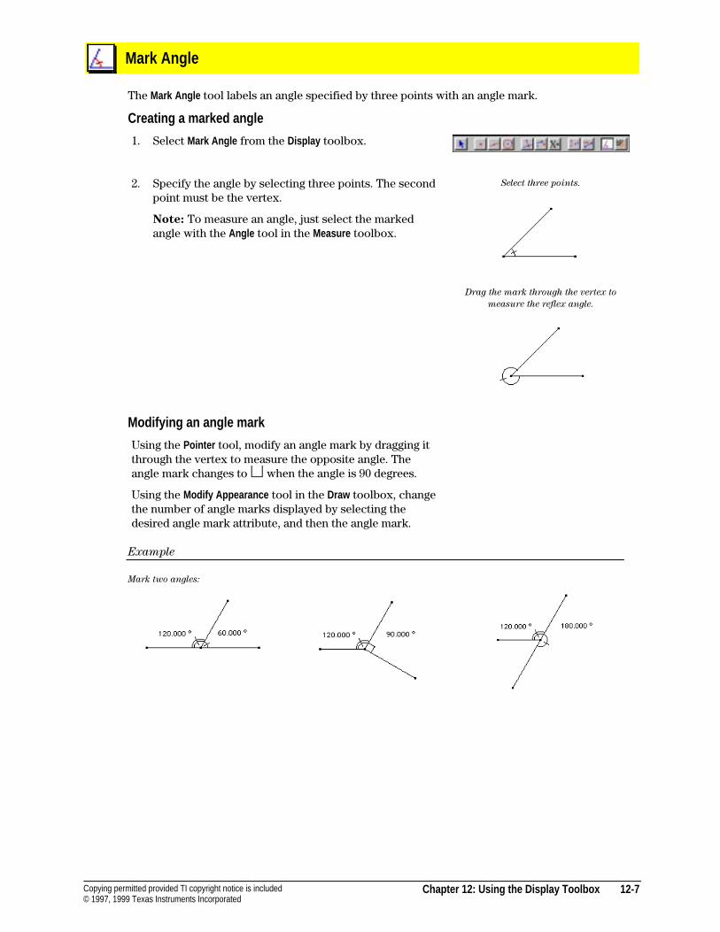
Chapter 12: Using the Display Toolbox 12-7Copying permitted provided TI copyright notice is included© 1997, 1999 Texas Instruments Incorporated
Mark Angle
The Mark Angle tool labels an angle specified by three points with an angle mark.
Creating a marked angle
1. Select Mark Angle from the Display toolbox.
2. Specify the angle by selecting three points. The secondpoint must be the vertex.
Note: To measure an angle, just select the markedangle with the Angle tool in the Measure toolbox.
Select three points.
Drag the mark through the vertex to
measure the reflex angle.
Modifying an angle mark
Using the Pointer tool, modify an angle mark by dragging itthrough the vertex to measure the opposite angle. Theangle mark changes to � when the angle is 90 degrees.
Using the Modify Appearance tool in the Draw toolbox, changethe number of angle marks displayed by selecting thedesired angle mark attribute, and then the angle mark.
Example
Mark two angles:
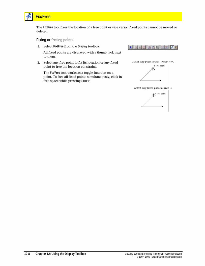
12-8 Chapter 12: Using the Display Toolbox Copying permitted provided TI copyright notice is included© 1997, 1999 Texas Instruments Incorporated
Fix/Free
The Fix/Free tool fixes the location of a free point or vice versa. Fixed points cannot be moved ordeleted.
Fixing or freeing points
1. Select Fix/Free from the Display toolbox.
All fixed points are displayed with a thumb tack nextto them.
2. Select any free point to fix its location or any fixedpoint to free the location constraint.
The Fix/Free tool works as a toggle function on apoint. To free all fixed points simultaneously, click infree space while pressing SHIFT.
Select any point to fix its position.
Select any fixed point to free it.
This point
This point
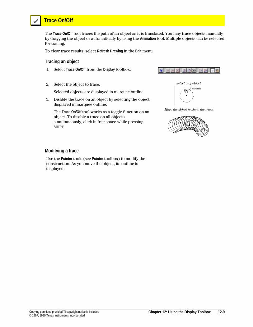
Chapter 12: Using the Display Toolbox 12-9Copying permitted provided TI copyright notice is included© 1997, 1999 Texas Instruments Incorporated
Trace On/Off
The Trace On/Off tool traces the path of an object as it is translated. You may trace objects manuallyby dragging the object or automatically by using the Animation tool. Multiple objects can be selectedfor tracing.
To clear trace results, select Refresh Drawing in the Edit menu.
Tracing an object
1. Select Trace On/Off from the Display toolbox.
2. Select the object to trace.
Selected objects are displayed in marquee outline.
3. Disable the trace on an object by selecting the objectdisplayed in marquee outline.
The Trace On/Off tool works as a toggle function on anobject. To disable a trace on all objectssimultaneously, click in free space while pressingSHIFT.
Select any object.
Move the object to show the trace.
Modifying a trace
Use the Pointer tools (see Pointer toolbox) to modify theconstruction. As you move the object, its outline isdisplayed.
This circle
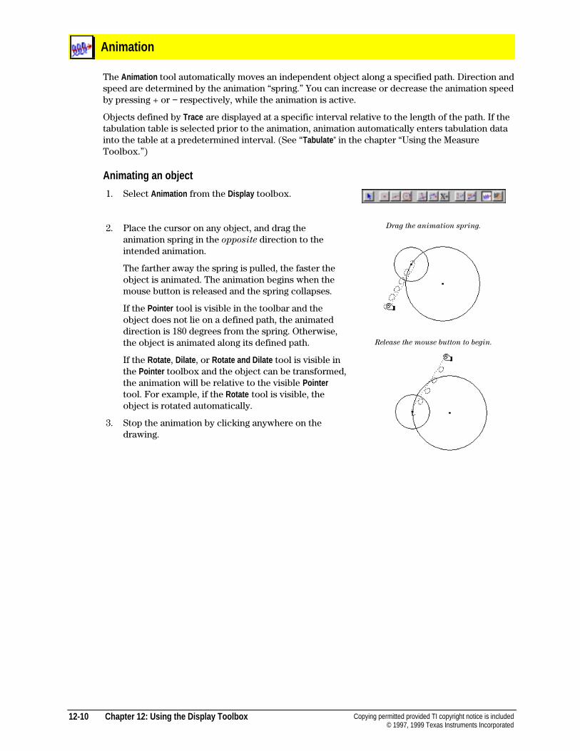
12-10 Chapter 12: Using the Display Toolbox Copying permitted provided TI copyright notice is included© 1997, 1999 Texas Instruments Incorporated
Animation
The Animation tool automatically moves an independent object along a specified path. Direction andspeed are determined by the animation “spring.” You can increase or decrease the animation speedby pressing + or − respectively, while the animation is active.
Objects defined by Trace are displayed at a specific interval relative to the length of the path. If thetabulation table is selected prior to the animation, animation automatically enters tabulation datainto the table at a predetermined interval. (See “Tabulate ” in the chapter “Using the MeasureToolbox.”)
Animating an object
1. Select Animation from the Display toolbox.
2. Place the cursor on any object, and drag theanimation spring in the opposite direction to theintended animation.
The farther away the spring is pulled, the faster theobject is animated. The animation begins when themouse button is released and the spring collapses.
If the Pointer tool is visible in the toolbar and theobject does not lie on a defined path, the animateddirection is 180 degrees from the spring. Otherwise,the object is animated along its defined path.
If the Rotate , Dilate , or Rotate and Dilate tool is visible inthe Pointer toolbox and the object can be transformed,the animation will be relative to the visible Pointertool. For example, if the Rotate tool is visible, theobject is rotated automatically.
3. Stop the animation by clicking anywhere on thedrawing.
Drag the animation spring.
Release the mouse button to begin.
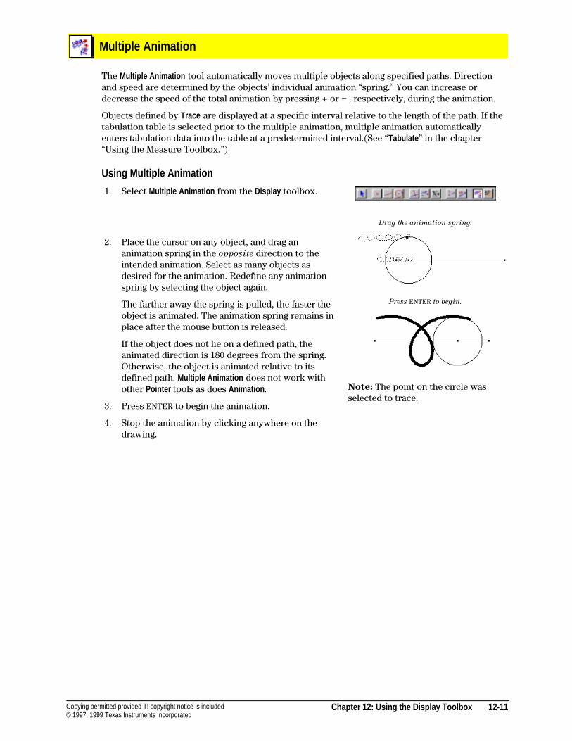
Chapter 12: Using the Display Toolbox 12-11Copying permitted provided TI copyright notice is included© 1997, 1999 Texas Instruments Incorporated
Multiple Animation
The Multiple Animation tool automatically moves multiple objects along specified paths. Directionand speed are determined by the objects’ individual animation “spring.” You can increase ordecrease the speed of the total animation by pressing + or − , respectively, during the animation.
Objects defined by Trace are displayed at a specific interval relative to the length of the path. If thetabulation table is selected prior to the multiple animation, multiple animation automaticallyenters tabulation data into the table at a predetermined interval.(See “Tabulate ” in the chapter“Using the Measure Toolbox.”)
Using Multiple Animation
1. Select Multiple Animation from the Display toolbox.
2. Place the cursor on any object, and drag ananimation spring in the opposite direction to theintended animation. Select as many objects asdesired for the animation. Redefine any animationspring by selecting the object again.
The farther away the spring is pulled, the faster theobject is animated. The animation spring remains inplace after the mouse button is released.
If the object does not lie on a defined path, theanimated direction is 180 degrees from the spring.Otherwise, the object is animated relative to itsdefined path. Multiple Animation does not work withother Pointer tools as does Animation .
3. Press ENTER to begin the animation.
4. Stop the animation by clicking anywhere on thedrawing.
Drag the animation spring.
Press ENTER to begin.
Note: The point on the circle wasselected to trace.
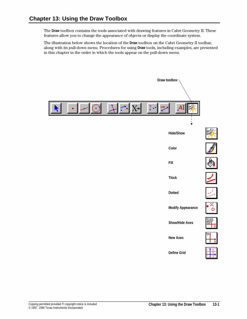
Chapter 13: Using the Draw Toolbox 13-1Copying permitted provided TI copyright notice is included© 1997, 1999 Texas Instruments Incorporated
Chapter 13: Using the Draw Toolbox
The Draw toolbox contains the tools associated with drawing features in Cabri Geometry II. Thesefeatures allow you to change the appearance of objects or display the coordinate system.
The illustration below shows the location of the Draw toolbox on the Cabri Geometry II toolbar,along with its pull-down menu. Procedures for using Draw tools, including examples, are presentedin this chapter in the order in which the tools appear on the pull-down menu.
Hide/Show
Color
Fill
Thick
Dotted
Modify Appearance
Show/Hide Axes
New Axes
Define Grid
Draw toolbox
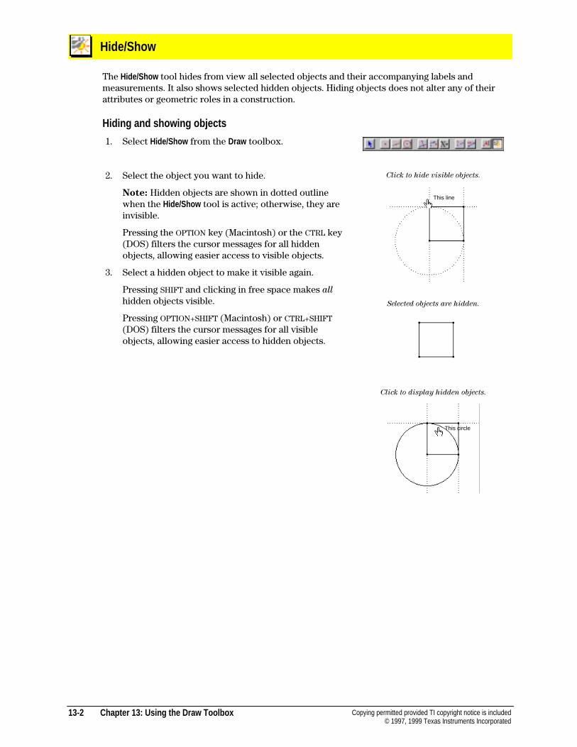
13-2 Chapter 13: Using the Draw Toolbox Copying permitted provided TI copyright notice is included© 1997, 1999 Texas Instruments Incorporated
Hide/Show
The Hide/Show tool hides from view all selected objects and their accompanying labels andmeasurements. It also shows selected hidden objects. Hiding objects does not alter any of theirattributes or geometric roles in a construction.
Hiding and showing objects
1. Select Hide/Show from the Draw toolbox.
2. Select the object you want to hide.
Note: Hidden objects are shown in dotted outlinewhen the Hide/Show tool is active; otherwise, they areinvisible.
Pressing the OPTION key (Macintosh) or the CTRL key(DOS) filters the cursor messages for all hiddenobjects, allowing easier access to visible objects.
3. Select a hidden object to make it visible again.
Pressing SHIFT and clicking in free space makes all
hidden objects visible.
Pressing OPTION+SHIFT (Macintosh) or CTRL+SHIFT(DOS) filters the cursor messages for all visibleobjects, allowing easier access to hidden objects.
Click to hide visible objects.
Selected objects are hidden.
Click to display hidden objects.
This circle
This line
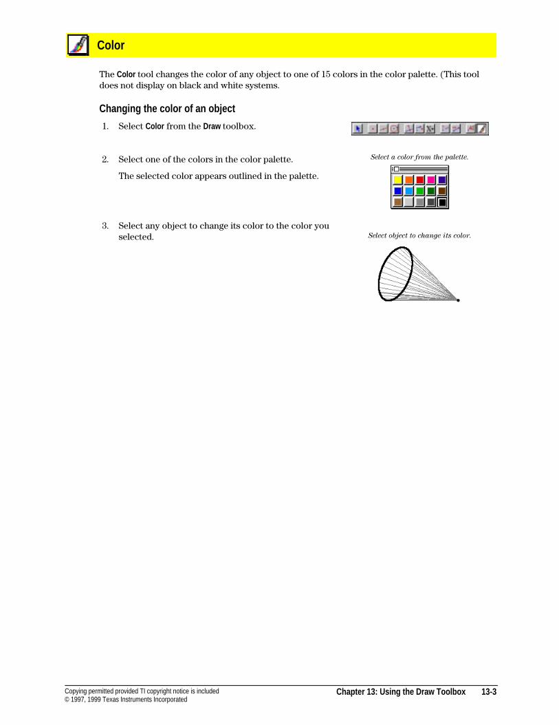
Chapter 13: Using the Draw Toolbox 13-3Copying permitted provided TI copyright notice is included© 1997, 1999 Texas Instruments Incorporated
Color
The Color tool changes the color of any object to one of 15 colors in the color palette. (This tooldoes not display on black and white systems.
Changing the color of an object
1. Select Color from the Draw toolbox.
2. Select one of the colors in the color palette.
The selected color appears outlined in the palette.
3. Select any object to change its color to the color youselected.
Select a color from the palette.
Select object to change its color.
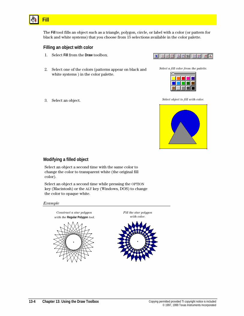
13-4 Chapter 13: Using the Draw Toolbox Copying permitted provided TI copyright notice is included© 1997, 1999 Texas Instruments Incorporated
Fill
The Fill tool fills an object such as a triangle, polygon, circle, or label with a color (or pattern forblack and white systems) that you choose from 15 selections available in the color palette.
Filling an object with color
1. Select Fill from the Draw toolbox.
2. Select one of the colors (patterns appear on black andwhite systems ) in the color palette.
Select a fill color from the palette.
3. Select an object. Select object to fill with color.
Modifying a filled object
Select an object a second time with the same color tochange the color to transparent white (the original fillcolor).
Select an object a second time while pressing the OPTIONkey (Macintosh) or the ALT key (Windows, DOS) to changethe color to opaque white.
Example
Construct a star polygon
with the Regular Polygon tool.
Fill the star polygon
with color.
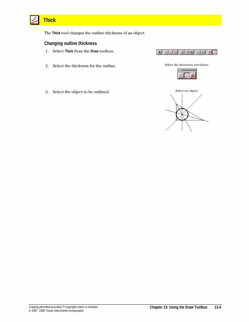
Chapter 13: Using the Draw Toolbox 13-5Copying permitted provided TI copyright notice is included© 1997, 1999 Texas Instruments Incorporated
Thick
The Thick tool changes the outline thickness of an object.
Changing outline thickness
1. Select Thick from the Draw toolbox.
2. Select the thickness for the outline. Select the thickness attributes.
3. Select the object to be outlined. Select an object.
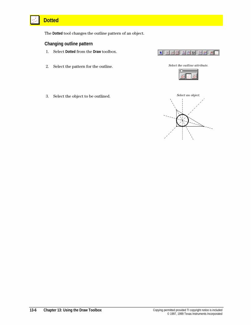
13-6 Chapter 13: Using the Draw Toolbox Copying permitted provided TI copyright notice is included© 1997, 1999 Texas Instruments Incorporated
Dotted
The Dotted tool changes the outline pattern of an object.
Changing outline pattern
1. Select Dotted from the Draw toolbox.
2. Select the pattern for the outline. Select the outline attribute.
3. Select the object to be outlined. Select an object.
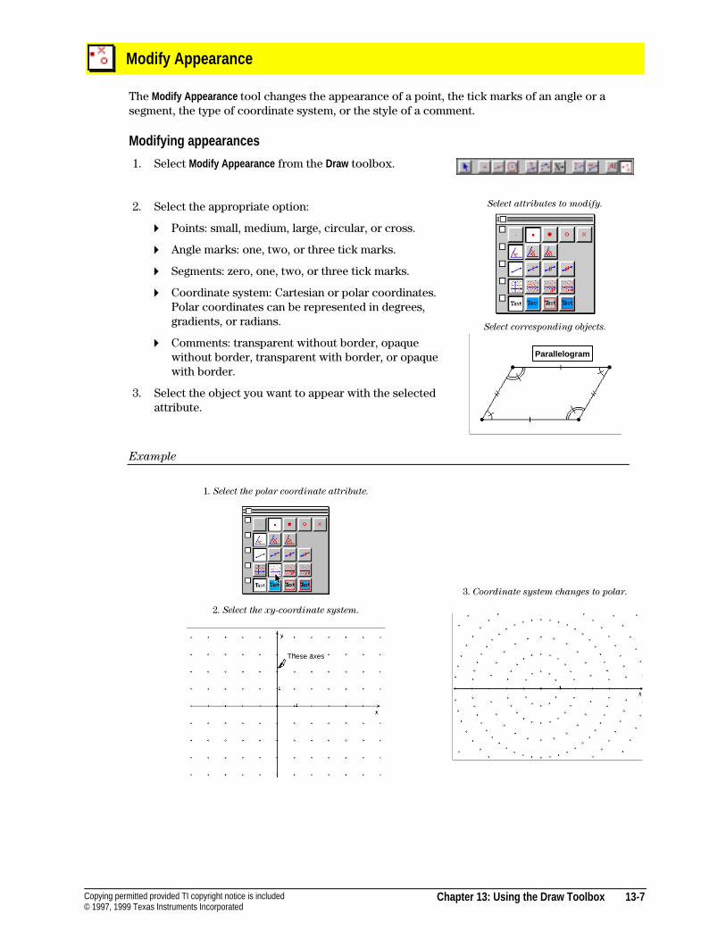
Chapter 13: Using the Draw Toolbox 13-7Copying permitted provided TI copyright notice is included© 1997, 1999 Texas Instruments Incorporated
Modify Appearance
The Modify Appearance tool changes the appearance of a point, the tick marks of an angle or asegment, the type of coordinate system, or the style of a comment.
Modifying appearances
1. Select Modify Appearance from the Draw toolbox.
2. Select the appropriate option:
4 Points: small, medium, large, circular, or cross.
4 Angle marks: one, two, or three tick marks.
4 Segments: zero, one, two, or three tick marks.
4 Coordinate system: Cartesian or polar coordinates.Polar coordinates can be represented in degrees,gradients, or radians.
4 Comments: transparent without border, opaquewithout border, transparent with border, or opaquewith border.
3. Select the object you want to appear with the selectedattribute.
Select attributes to modify.
Select corresponding objects.
Example
1. Select the polar coordinate attribute.
2. Select the xy-coordinate system.
3. Coordinate system changes to polar.
These axes
Parallelogram
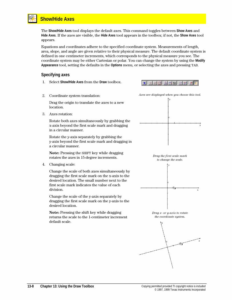
13-8 Chapter 13: Using the Draw Toolbox Copying permitted provided TI copyright notice is included© 1997, 1999 Texas Instruments Incorporated
Show/Hide Axes
The Show/Hide Axes tool displays the default axes. This command toggles between Show Axes andHide Axes . If the axes are visible, the Hide Axes tool appears in the toolbox; if not, the Show Axes toolappears.
Equations and coordinates adhere to the specified coordinate system. Measurements of length,area, slope, and angle are given relative to their physical measure. The default coordinate system isdefined in one centimeter increments, which corresponds to the physical measure you see. Thecoordinate system may be either Cartesian or polar. You can change the system by using the ModifyAppearance tool, setting the defaults in the Options menu, or selecting the axes and pressing TAB.
Specifying axes
1. Select Show/Hide Axes from the Draw toolbox.
2. Coordinate system translation:
Drag the origin to translate the axes to a newlocation.
3. Axes rotation:
Rotate both axes simultaneously by grabbing thex-axis beyond the first scale mark and draggingin a circular manner.
Rotate the y-axis separately by grabbing they-axis beyond the first scale mark and dragging ina circular manner.
Note: Pressing the SHIFT key while draggingrotates the axes in 15-degree increments.
4. Changing scale:
Change the scale of both axes simultaneously bydragging the first scale mark on the x-axis to thedesired location. The small number next to thefirst scale mark indicates the value of eachdivision.
Change the scale of the y-axis separately bydragging the first scale mark on the y-axis to thedesired location.
Note: Pressing the shift key while draggingreturns the scale to the 1-centimeter incrementdefault scale.
Axes are displayed when you choose this tool.
Drag the first scale mark
to change the scale.
Drag x- or y-axis to rotate
the coordinate system.
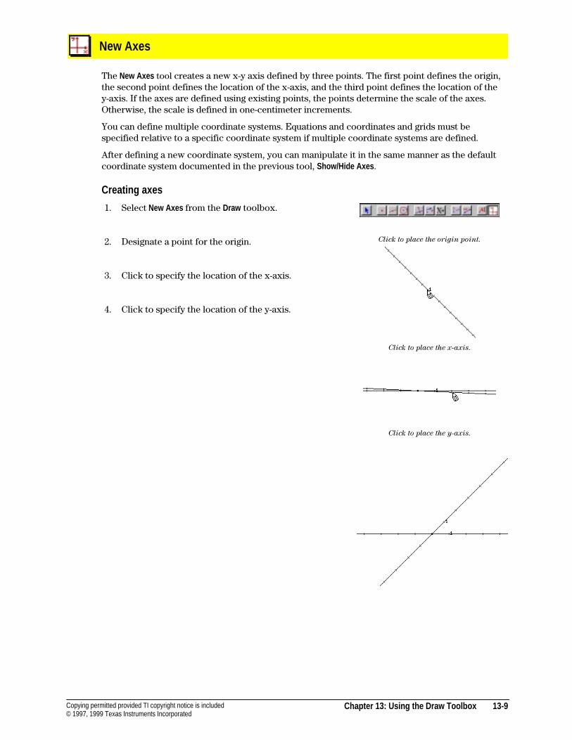
Chapter 13: Using the Draw Toolbox 13-9Copying permitted provided TI copyright notice is included© 1997, 1999 Texas Instruments Incorporated
New Axes
The New Axes tool creates a new x-y axis defined by three points. The first point defines the origin,the second point defines the location of the x-axis, and the third point defines the location of they-axis. If the axes are defined using existing points, the points determine the scale of the axes.Otherwise, the scale is defined in one-centimeter increments.
You can define multiple coordinate systems. Equations and coordinates and grids must bespecified relative to a specific coordinate system if multiple coordinate systems are defined.
After defining a new coordinate system, you can manipulate it in the same manner as the defaultcoordinate system documented in the previous tool, Show/Hide Axes .
Creating axes
1. Select New Axes from the Draw toolbox.
2. Designate a point for the origin.
3. Click to specify the location of the x-axis.
4. Click to specify the location of the y-axis.
Click to place the origin point.
Click to place the x-axis.
Click to place the y-axis.
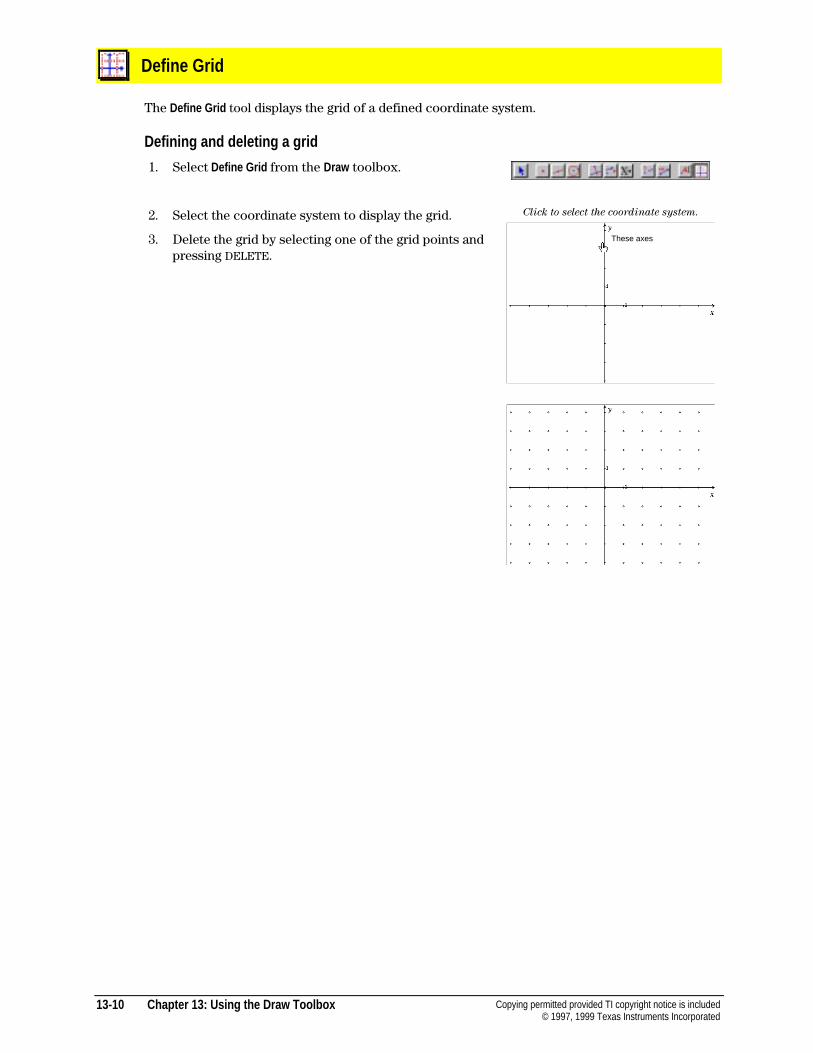
13-10 Chapter 13: Using the Draw Toolbox Copying permitted provided TI copyright notice is included© 1997, 1999 Texas Instruments Incorporated
Define Grid
The Define Grid tool displays the grid of a defined coordinate system.
Defining and deleting a grid
1. Select Define Grid from the Draw toolbox.
2. Select the coordinate system to display the grid.
3. Delete the grid by selecting one of the grid points andpressing DELETE.
Click to select the coordinate system.
These axes
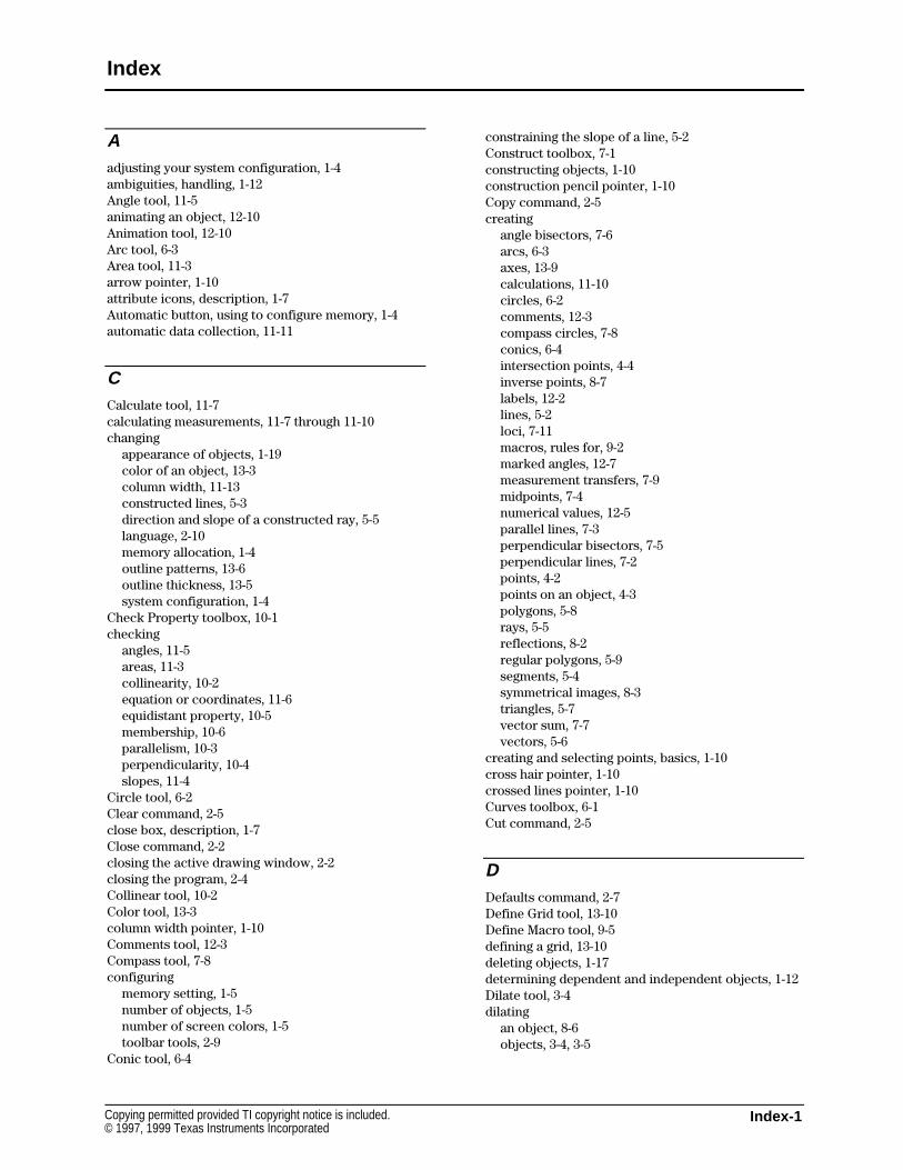
Index-1Copying permitted provided TI copyright notice is included.© 1997, 1999 Texas Instruments Incorporated
Aadjusting your system configuration, 1-4ambiguities, handling, 1-12Angle tool, 11-5animating an object, 12-10Animation tool, 12-10Arc tool, 6-3Area tool, 11-3arrow pointer, 1-10attribute icons, description, 1-7Automatic button, using to configure memory, 1-4automatic data collection, 11-11
CCalculate tool, 11-7calculating measurements, 11-7 through 11-10changing
appearance of objects, 1-19color of an object, 13-3column width, 11-13constructed lines, 5-3direction and slope of a constructed ray, 5-5language, 2-10memory allocation, 1-4outline patterns, 13-6outline thickness, 13-5system configuration, 1-4
Check Property toolbox, 10-1checking
angles, 11-5areas, 11-3collinearity, 10-2equation or coordinates, 11-6equidistant property, 10-5membership, 10-6parallelism, 10-3perpendicularity, 10-4slopes, 11-4
Circle tool, 6-2Clear command, 2-5close box, description, 1-7Close command, 2-2closing the active drawing window, 2-2closing the program, 2-4Collinear tool, 10-2Color tool, 13-3column width pointer, 1-10Comments tool, 12-3Compass tool, 7-8configuring
memory setting, 1-5number of objects, 1-5number of screen colors, 1-5toolbar tools, 2-9
Conic tool, 6-4
constraining the slope of a line, 5-2Construct toolbox, 7-1constructing objects, 1-10construction pencil pointer, 1-10Copy command, 2-5creating
angle bisectors, 7-6arcs, 6-3axes, 13-9calculations, 11-10circles, 6-2comments, 12-3compass circles, 7-8conics, 6-4intersection points, 4-4inverse points, 8-7labels, 12-2lines, 5-2loci, 7-11macros, rules for, 9-2marked angles, 12-7measurement transfers, 7-9midpoints, 7-4numerical values, 12-5parallel lines, 7-3perpendicular bisectors, 7-5perpendicular lines, 7-2points, 4-2points on an object, 4-3polygons, 5-8rays, 5-5reflections, 8-2regular polygons, 5-9segments, 5-4symmetrical images, 8-3triangles, 5-7vector sum, 7-7vectors, 5-6
creating and selecting points, basics, 1-10cross hair pointer, 1-10crossed lines pointer, 1-10Curves toolbox, 6-1Cut command, 2-5
DDefaults command, 2-7Define Grid tool, 13-10Define Macro tool, 9-5defining a grid, 13-10deleting objects, 1-17determining dependent and independent objects, 1-12Dilate tool, 3-4dilating
an object, 8-6objects, 3-4, 3-5
Index
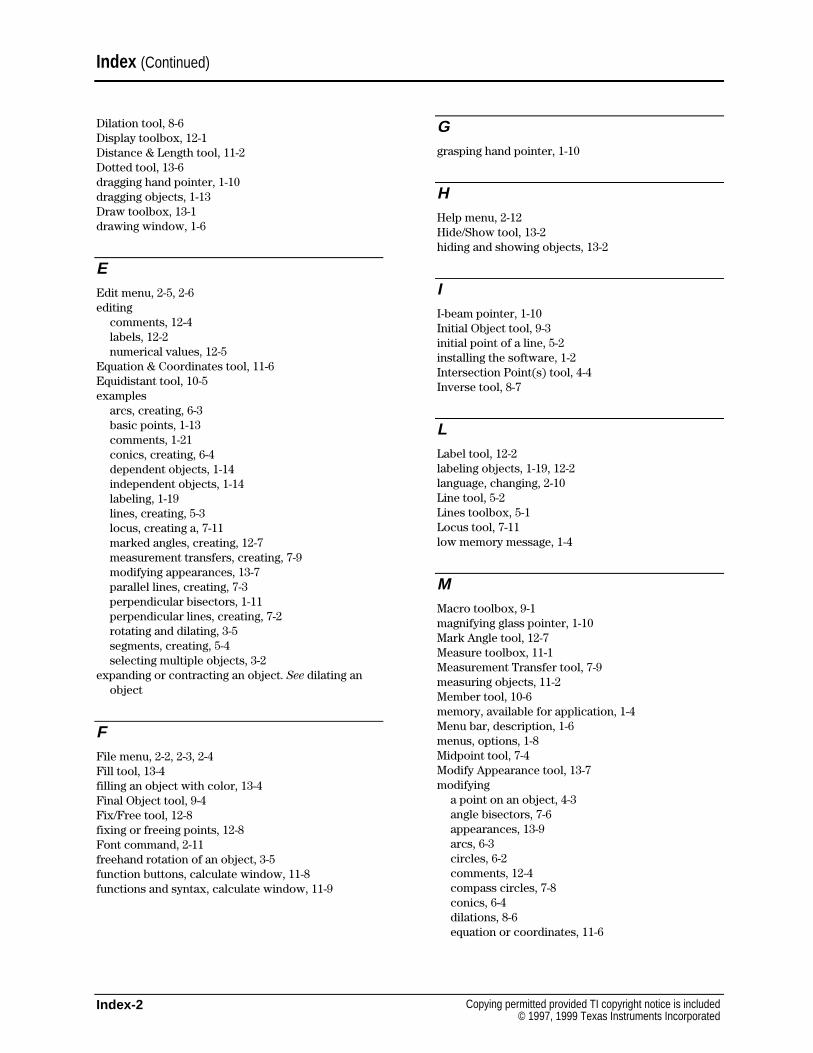
Index-2 Copying permitted provided TI copyright notice is included© 1997, 1999 Texas Instruments Incorporated
Dilation tool, 8-6Display toolbox, 12-1Distance & Length tool, 11-2Dotted tool, 13-6dragging hand pointer, 1-10dragging objects, 1-13Draw toolbox, 13-1drawing window, 1-6
EEdit menu, 2-5, 2-6editing
comments, 12-4labels, 12-2numerical values, 12-5
Equation & Coordinates tool, 11-6Equidistant tool, 10-5examples
arcs, creating, 6-3basic points, 1-13comments, 1-21conics, creating, 6-4dependent objects, 1-14independent objects, 1-14labeling, 1-19lines, creating, 5-3locus, creating a, 7-11marked angles, creating, 12-7measurement transfers, creating, 7-9modifying appearances, 13-7parallel lines, creating, 7-3perpendicular bisectors, 1-11perpendicular lines, creating, 7-2rotating and dilating, 3-5segments, creating, 5-4selecting multiple objects, 3-2
expanding or contracting an object. See dilating anobject
FFile menu, 2-2, 2-3, 2-4Fill tool, 13-4filling an object with color, 13-4Final Object tool, 9-4Fix/Free tool, 12-8fixing or freeing points, 12-8Font command, 2-11freehand rotation of an object, 3-5function buttons, calculate window, 11-8functions and syntax, calculate window, 11-9
Ggrasping hand pointer, 1-10
HHelp menu, 2-12Hide/Show tool, 13-2hiding and showing objects, 13-2
II-beam pointer, 1-10Initial Object tool, 9-3initial point of a line, 5-2installing the software, 1-2Intersection Point(s) tool, 4-4Inverse tool, 8-7
LLabel tool, 12-2labeling objects, 1-19, 12-2language, changing, 2-10Line tool, 5-2Lines toolbox, 5-1Locus tool, 7-11low memory message, 1-4
MMacro toolbox, 9-1magnifying glass pointer, 1-10Mark Angle tool, 12-7Measure toolbox, 11-1Measurement Transfer tool, 7-9measuring objects, 11-2Member tool, 10-6memory, available for application, 1-4Menu bar, description, 1-6menus, options, 1-8Midpoint tool, 7-4Modify Appearance tool, 13-7modifying
a point on an object, 4-3angle bisectors, 7-6appearances, 13-9arcs, 6-3circles, 6-2comments, 12-4compass circles, 7-8conics, 6-4dilations, 8-6equation or coordinates, 11-6
Index (Continued)
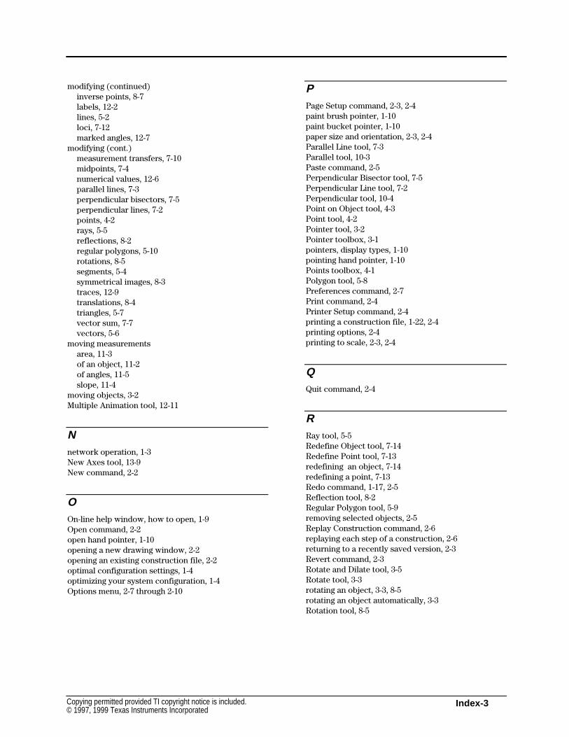
Index-3Copying permitted provided TI copyright notice is included.© 1997, 1999 Texas Instruments Incorporated
modifying (continued)inverse points, 8-7labels, 12-2lines, 5-2loci, 7-12marked angles, 12-7
modifying (cont.)measurement transfers, 7-10midpoints, 7-4numerical values, 12-6parallel lines, 7-3perpendicular bisectors, 7-5perpendicular lines, 7-2points, 4-2rays, 5-5reflections, 8-2regular polygons, 5-10rotations, 8-5segments, 5-4symmetrical images, 8-3traces, 12-9translations, 8-4triangles, 5-7vector sum, 7-7vectors, 5-6
moving measurementsarea, 11-3of an object, 11-2of angles, 11-5slope, 11-4
moving objects, 3-2Multiple Animation tool, 12-11
Nnetwork operation, 1-3New Axes tool, 13-9New command, 2-2
OOn-line help window, how to open, 1-9Open command, 2-2open hand pointer, 1-10opening a new drawing window, 2-2opening an existing construction file, 2-2optimal configuration settings, 1-4optimizing your system configuration, 1-4Options menu, 2-7 through 2-10
PPage Setup command, 2-3, 2-4paint brush pointer, 1-10paint bucket pointer, 1-10paper size and orientation, 2-3, 2-4Parallel Line tool, 7-3Parallel tool, 10-3Paste command, 2-5Perpendicular Bisector tool, 7-5Perpendicular Line tool, 7-2Perpendicular tool, 10-4Point on Object tool, 4-3Point tool, 4-2Pointer tool, 3-2Pointer toolbox, 3-1pointers, display types, 1-10pointing hand pointer, 1-10Points toolbox, 4-1Polygon tool, 5-8Preferences command, 2-7Print command, 2-4Printer Setup command, 2-4printing a construction file, 1-22, 2-4printing options, 2-4printing to scale, 2-3, 2-4
QQuit command, 2-4
RRay tool, 5-5Redefine Object tool, 7-14Redefine Point tool, 7-13redefining an object, 7-14redefining a point, 7-13Redo command, 1-17, 2-5Reflection tool, 8-2Regular Polygon tool, 5-9removing selected objects, 2-5Replay Construction command, 2-6replaying each step of a construction, 2-6returning to a recently saved version, 2-3Revert command, 2-3Rotate and Dilate tool, 3-5Rotate tool, 3-3rotating an object, 3-3, 8-5rotating an object automatically, 3-3Rotation tool, 8-5
Index-4 Copying permitted provided TI copyright notice is included© 1997, 1999 Texas Instruments Incorporated
SSave and Save As command, 2-2saving a construction file, 1-22, 2-2scroll bars, description, 1-7scrolling the drawing window, 1-22Segment tool, 5-4Select All command, 2-6selecting
all objects, 2-5default colors and attribute settings, 2-7objects, 3-2preferences, 2-7
selection hand pointer, 1-10selection pencil pointer, 1-10selection pointer, description, 1-7setting preferences, 2-7Show Drawing command, 2-3Show/Hide Attributes command, 2-7Show/Hide Axes tool, 13-8size box, description, 1-7Size command, 2-11Slope tool, 11-4specifying
axes, 13-8final objects, 9-4initial objects, 9-3macros, 9-6
starting the program, 1-3status, checking, 1-5storing a macro in memory, 9-2, 9-5Style command, 2-11, 2-12Symmetry tool, 8-3system requirements, 1-2
Ttable dimensions, using Tabulate, 11-11Tabulate tool
adding values, 11-12description, 11-11sizing and deleting columns, 11-13using tabulate, 11-12
Thick tool, 13-5Tool Configuration command, 2-9Toolbar, description, 1-7
toolboxesCheck Property, 10-1Construct, 7-1Curves, 6-1Display, 12-1Draw, 13-1Lines, 5-1Macro, 9-1Measure, 11-1Pointer, 3-1Points, 4-1Transform, 8-1
Trace On/Off tool, 12-9tracing an object, 12-9Transform toolbox, 8-1translating
lines, 5-2objects, 8-4rays, 5-5segments, 5-4vectors, constructed, 5-6
Translation tool, 8-4Triangle tool, 5-7
UUndo command, 1-17, 2-5using the software on a network, 1-3
VVector Sum tool, 7-7Vector tool, 5-6viewing
font sizes, 2-11installed fonts, 2-11text styles, 2-11
viewing an entire region, 2-3viewing available system memory, 1-4
Zzoom box, description, 1-7
Index (Continued)