CableAnalyzer - Microsoft · 1 DTX Series CableAnalyzer Overview of Features The DTX Series...
70
DTX Series CableAnalyzer Users Manual PN 2142201 April 2004 Rev. 1 11/04 © 2004 Fluke Corporation. All rights reserved. Printed in USA. All product names are trademarks of their respective companies.
Transcript of CableAnalyzer - Microsoft · 1 DTX Series CableAnalyzer Overview of Features The DTX Series...

DTX Series CableAnalyzer
Users Manual
PN 2142201 April 2004 Rev. 1 11/04 © 2004 Fluke Corporation. All rights reserved. Printed in USA. All product names are trademarks of their respective companies.

LIMITED WARRANTY AND LIMITATION OF LIABILITY Each Fluke Networks product is warranted to be free from defects in material and workmanship under normal use and service. The warranty period for the mainframe is one year and begins on the date of purchase. Parts, accessories, product repairs and services are warranted for 90 days, unless otherwise stated. Ni-Cad, Ni-MH and Li-Ion batteries, cables or other peripherals are all considered parts or accessories. The warranty extends only to the original buyer or end user customer of a Fluke Networks authorized reseller, and does not apply to any prod-uct which, in Fluke Networks’ opinion, has been misused, abused, altered, neglected, contaminated, or damaged by accident or abnormal conditions of operation or handling. Fluke Networks warrants that software will operate substantially in accordance with its functional specifications for 90 days and that it has been properly recorded on non-defective media. Fluke Networks does not warrant that software will be error free or operate without interruption. Fluke Networks authorized resellers shall extend this warranty on new and unused products to end-user customers only but have no author-ity to extend a greater or different warranty on behalf of Fluke Networks. Warranty support is available only if product is purchased through a Fluke Networks authorized sales outlet or Buyer has paid the applicable international price. Fluke Networks reserves the right to invoice Buyer for importation costs of repair/replacement parts when product purchased in one country is submitted for repair in another country. Fluke Networks' warranty obligation is limited, at Fluke Networks' option, to refund of the purchase price, free of charge repair, or replace-ment of a defective product which is returned to a Fluke Networks authorized service center within the warranty period. To obtain warranty service, contact your nearest Fluke Networks authorized service center to obtain return authorization information, then send the product to that service center, with a description of the difficulty, postage and insurance prepaid (FOB Destination). Fluke Net-works assumes no risk for damage in transit. Following warranty repair, the product will be returned to Buyer, transportation prepaid (FOB Destination). If Fluke Networks determines that failure was caused by neglect, misuse, contamination, alteration, accident or abnormal condition of operation or handling, or normal wear and tear of mechanical components, Fluke Networks will provide an estimate of repair costs and obtain authorization before commencing the work. Following repair, the product will be returned to the Buyer transportation prepaid and the Buyer will be billed for the repair and return transportation charges (FOB Shipping Point). THIS WARRANTY IS BUYER'S SOLE AND EXCLUSIVE REMEDY AND IS IN LIEU OF ALL OTHER WARRANTIES, EXPRESS OR IMPLIED, INCLUDING BUT NOT LIMITED TO ANY IMPLIED WARRANTY OF MERCHANTABILITY OR FITNESS FOR A PARTICULAR PURPOSE. FLUKE NETWORKS SHALL NOT BE LIABLE FOR ANY SPECIAL, INDIRECT, INCIDENTAL OR CONSEQUENTIAL DAMAGES OR LOSSES, INCLUDING LOSS OF DATA, ARISING FROM ANY CAUSE OR THEORY. Since some countries or states do not allow limitation of the term of an implied warranty, or exclusion or limitation of incidental or conse-quential damages, the limitations and exclusions of this warranty may not apply to every buyer. If any provision of this Warranty is held invalid or unenforceable by a court or other decision-maker of competent jurisdiction, such holding will not affect the validity or enforce-ability of any other provision. 4/04
Fluke Networks PO Box 777 Everett, WA 98206-0777 USA
i
Table of Contents
Title Page Overview of Features.................................................................................................... 1 Registration................................................................................................................... 2 Contacting Fluke Networks .......................................................................................... 2 Accessing the Technical Reference Handbook ............................................................ 3 Additional Resources for Cable Testing Information.................................................. 3 Unpacking ..................................................................................................................... 4
DTX-1800 .................................................................................................................. 4 DTX-1200 .................................................................................................................. 4 DTX-LT ...................................................................................................................... 5
Safety Information........................................................................................................ 5 Getting Acquainted ...................................................................................................... 8
Physical Features ...................................................................................................... 8 Powering the Tester................................................................................................. 14 Localizing the Tester ................................................................................................ 14 About Link Interface Adapters ................................................................................ 16
Preparing to Save Tests................................................................................................. 19

DTX Series CableAnalyzer Users Manual
ii
Certifying Twisted Pair Cabling ................................................................................... 20 Setting the Reference for Twisted Pair Cabling..................................................... 20 Twisted Pair Test Settings........................................................................................ 22 Autotest on Twisted Pair Cabling ........................................................................... 25 Autotest Summary Results for Twisted Pair Cabling.............................................. 29 PASS*/FAIL* Results ................................................................................................. 30
Automatic Diagnostics ................................................................................................. 31 Certifying Coaxial Cabling ........................................................................................... 32
Setting the Reference for Coaxial Cabling ............................................................. 32 Coaxial Test Settings................................................................................................ 34 Autotest on Coaxial Cabling ................................................................................... 36 Autotest Results for Coaxial Cabling ...................................................................... 40
Cable ID Options........................................................................................................... 41 Memory Functions........................................................................................................ 42
Formatting the Memory Card (DTX-1800 and DTX-1200) or Internal Memory... 42 Setting the Storage Location (DTX-1800 and DTX-1200) ..................................... 42 Viewing Results........................................................................................................ 42 Moving and Deleting Results .................................................................................. 43
DTX-1800, DTX-1200 ........................................................................................... 43 All Models ........................................................................................................... 43
Uploading Results to a PC ....................................................................................... 44 Options and Accessories............................................................................................... 45 About LinkWare and LinkWare Stats Software .......................................................... 50 Maintenance................................................................................................................. 51
Cleaning ................................................................................................................... 51 Factory Calibration .................................................................................................. 51 Updating the Tester’s Software .............................................................................. 52
Updating with a PC............................................................................................. 52

Contents (continued)
iii
Updating with Another Tester ........................................................................... 54 Updating with a Memory Card (DTX-1800, DTX-1200) .................................... 55
Retraining the Battery Gauge ................................................................................. 56 Certification and Compliance....................................................................................... 57
CSA Standards .......................................................................................................... 57 Safety ........................................................................................................................ 57
Index

DTX Series CableAnalyzer Users Manual
iv

v
List of Figures
Figure Title Page
1. Tester Front Panel Features ................................................................................................. 8 2. Tester Side and Top Panel Features .................................................................................... 10 3. Smart Remote Features........................................................................................................ 12 4. Removing the Battery Pack ................................................................................................. 15 5. Smart Remote Battery Status Shown After Power-Up....................................................... 15 6. Attaching and Removing Adapters..................................................................................... 16 7. Handling Guidelines for Permanent Link Adapters ........................................................... 17 8. Changing the Personality Module....................................................................................... 18 9. Twisted Pair Reference Connections................................................................................... 21 10. Equipment for Certifying Twisted Pair Cabling.................................................................. 25 11. Permanent Link Test Connections....................................................................................... 27 12. Channel Test Connections ................................................................................................... 28 13. Autotest Summary for Twisted Pair Cabling ...................................................................... 29 14. PASS* and FAIL* Results ...................................................................................................... 30 15. Examples of Automatic Diagnostic Screens ........................................................................ 31 16. Coaxial Pair Reference Connections.................................................................................... 33 17. Equipment for Certifying Coaxial Cabling.......................................................................... 36
DTX Series CableAnalyzer Users Manual
vi
18. Coaxial Network Cabling Test Connections ....................................................................... 38 19. Coaxial Video Cabling Test Connections ............................................................................ 39 20. Autotest Results for Coaxial Cabling .................................................................................. 40 21. Updating the Software with a PC....................................................................................... 53 22. Updating the Software with an Updated Tester ............................................................... 54
1
DTX Series CableAnalyzer
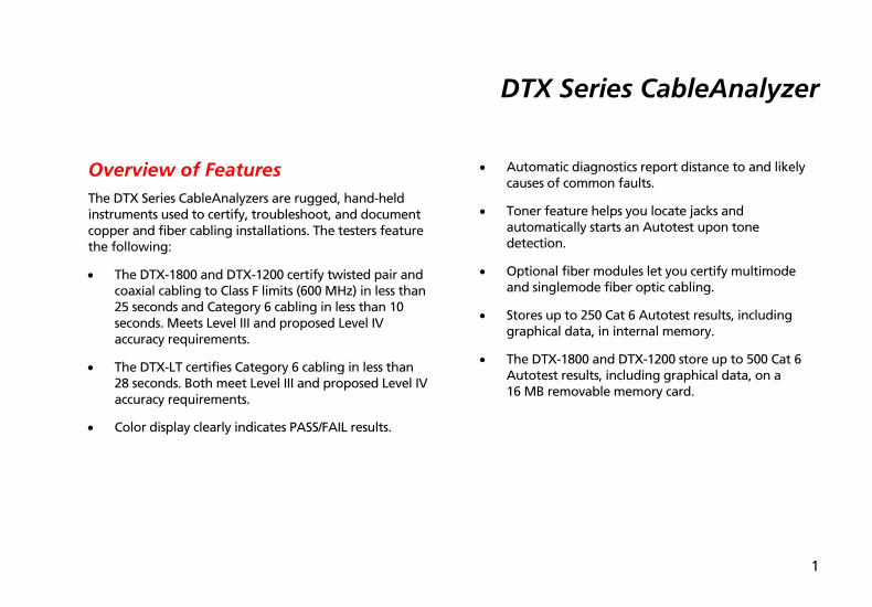
Overview of Features The DTX Series CableAnalyzers are rugged, hand-held instruments used to certify, troubleshoot, and document copper and fiber cabling installations. The testers feature the following:
• The DTX-1800 and DTX-1200 certify twisted pair and coaxial cabling to Class F limits (600 MHz) in less than 25 seconds and Category 6 cabling in less than 10 seconds. Meets Level III and proposed Level IV accuracy requirements.
• The DTX-LT certifies Category 6 cabling in less than 28 seconds. Both meet Level III and proposed Level IV accuracy requirements.
• Color display clearly indicates PASS/FAIL results.
• Automatic diagnostics report distance to and likely causes of common faults.
• Toner feature helps you locate jacks and automatically starts an Autotest upon tone detection.
• Optional fiber modules let you certify multimode and singlemode fiber optic cabling.
• Stores up to 250 Cat 6 Autotest results, including graphical data, in internal memory.
• The DTX-1800 and DTX-1200 store up to 500 Cat 6 Autotest results, including graphical data, on a 16 MB removable memory card.

DTX Series CableAnalyzer Users Manual
2
• Runs for at least 12 hours on the rechargeable lithium ion battery pack.
• Smart remote with optional fiber module can be used with Fluke Networks OF-500 OptiFiber Certifying OTDR for loss/length certification.
• LinkWare software lets you upload test results to a PC to create professional-quality test reports. The LinkWare Stats option generates browsable, graphical reports of cable test statistics.
Registration Registering your product with Fluke Networks gives you access to valuable information on product updates, troubleshooting tips, and other support services.
To register, fill out the online registration form on the Fluke Networks website at www.flukenetworks.com/registration.
Contacting Fluke Networks
Note
If you contact Fluke Networks about your tester, have the tester's software and hardware version numbers available if possible.
www.flukenetworks.com
+1-425-446-4519
• Australia: 61 (2) 8850-3333 or 61 (3) 9329 0244
• Beijing: 86 (10) 6512-3435
• Brazil: 11 3044 1277
• Canada: 1-800-363-5853
• Europe: +44 1923 281 300
• Hong Kong: 852 2721-3228
Accessing the Technical Reference Handbook
3
• Japan: +81-3-3434-0181
• Korea: 82 2 539-6311
• Singapore: +65-6738-5655
• Taiwan: (886) 2-227-83199
• USA: 1-800-283-5853
Visit our website for a complete list of phone numbers.
Accessing the Technical Reference Handbook The DTX CableAnalyzer Technical Reference Handbook provides additional information on the tester. The handbook is available on the DTX CableAnalyzer Product CD included with your tester and on the DTX CableAnalyzer product page on the Fluke Networks website.
Additional Resources for Cable Testing Information The Fluke Networks Knowledge Base answers common questions about Fluke Networks products and provides articles on cable testing techniques and technology.
To access the Knowledge Base, log on to www.flukenetworks.com, then click knowledge base at the top of the page.
The website cabletesting.com answers common questions about cable testing and provides articles on testing, documentation, and standards, and other reference information.

DTX Series CableAnalyzer Users Manual
4
Unpacking The DTX Series CableAnalyzers come with the accessories listed below. If something is damaged or missing, contact the place of purchase immediately.
DTX-1800 • DTX-1800 CableAnalyzer with lithium-ion battery
pack
• DTX-1800 SmartRemote with lithium-ion battery pack
• Two Cat 6/Class E permanent link adapters with personality modules
• Two Cat 6/Class E channel adapters
• Two headsets
• Carrying case
• Carrying strap
• Memory card
• USB cable for PC communications
• DTX RS-232 serial cable for PC communications
• Two ac adapters
• DTX Series CableAnalyzer Users Manual
• DTX Series CableAnalyzer Product CD
• LinkWare Software CD
DTX-1200 • DTX-1200 CableAnalyzer with lithium-ion battery
pack
• DTX-1200 SmartRemote with lithium-ion battery pack
• Two Cat 6/Class E permanent link adapters with personality modules
• Two Cat 6/Class E channel adapters
• Two headsets
• Carrying case
• Carrying strap
• USB cable for PC communications
• Two ac adapters
• DTX Series CableAnalyzer Users Manual
• DTX Series CableAnalyzer Product CD
• LinkWare Software CD

Safety Information
5
DTX-LT • DTX-LT CableAnalyzer with lithium-ion battery pack
• DTX-LT SmartRemote with lithium-ion battery pack
• Two Cat 6/Class E permanent link adapters with personality modules
• One Cat 6/Class E channel adapter
• Carrying strap
• USB cable for PC communications
• Two ac adapters
• DTX Series CableAnalyzer Users Manual
• DTX Series CableAnalyzer Product CD
• LinkWare Software CD
Safety Information
WXWarning
To avoid possible fire, electric shock, or personal injury:
• Do not open the case; no user-serviceable parts are inside.
• Do not modify the tester.
• Use only ac adapters approved by Fluke Networks for use with the DTX tester to charge the battery or power the tester.
• When servicing the tester, use only specified replacement parts.
• Do not use the tester if it is damaged. Inspect the tester before use.
• If this equipment is used in a manner not specified by the manufacturer, the protection provided by the equipment may be impaired.
DTX Series CableAnalyzer Users Manual
6
• Never connect the tester to any telephony inputs, systems, or equipment, including ISDN. Doing so is a misapplication of this product, which can result in damage to the tester and create a potential shock hazard to the user.
• Always turn on the tester before connecting it to a cable. Turning the tester on activates the tool’s input protection circuitry.
• Do not use the tester if it operates abnormally. Protection may be impaired.
Caution To avoid disrupting network operation, to avoid damaging the tester or cables under test, to avoid data loss, and to ensure maximum accuracy of test results:
• Never connect the tester to an active network. Doing so may disrupt network operation.
• Never attempt to insert any connector other than an 8-pin modular (RJ45) connector into an adapter’s jack. Inserting other connectors, such as RJ11 (telephone) connectors, can permanently damage the jack.
Safety Information
7
• Never operate portable transmitting devices, such as walkie-talkies and cell phones, during a cable test. Doing so might cause erroneous test results.
• To ensure maximum accuracy of copper cable test results, perform the reference procedure as described under “Setting the Reference” every 30 days.
• The permanent link interface adapters may not perform properly or may be damaged if they are handled improperly. See pages 16 and 17 for important handling information.
• Leave the module bay covers in place when the fiber modules are not installed. See page 10.
• Turn off the tester before attaching or removing modules.
• Never remove the memory card while the memory card’s LED is on. Doing so can corrupt the data on the card.
W* Warning: Class 1 and Class 2 Laser Products
To avoid possible eye damage caused by hazardous radiation, when using the fiber modules follow the safety guidelines given in the DTX-MFM/GFM/SFM Fiber Module Users Manual or the DTX Series CableAnalyzer Technical Reference Handbook.
DTX Series CableAnalyzer Users Manual
8
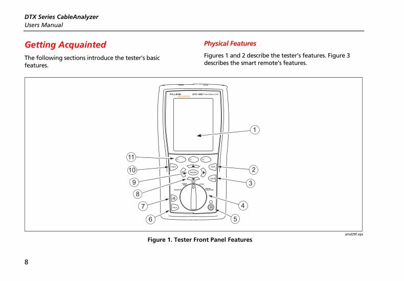
Getting Acquainted The following sections introduce the tester's basic features.
Physical Features
Figures 1 and 2 describe the tester’s features. Figure 3 describes the smart remote’s features.
TALK
MONITOR
ENTER
TEST
SAVE
SPECIAL FUNCTIONS
SETUP
AUTO TESTSINGLE
TEST
EXIT
F1 F2 F3
1
2
3
4
56
7
8
9
10
11
amd29f.eps
Figure 1. Tester Front Panel Features

Getting Acquainted
9
A LCD display with backlight and adjustable brightness.
B P: Starts the currently selected test. Activates the tone generator for twisted pair cabling if no smart remote is detected. The test starts when both testers are connected.
C N: Saves Autotest results in memory.
D Rotary switch selects the tester’s modes.
E M: On/off key.
F O: Press to use the headset to talk to the person at the other end of the link.
G G: Press to switch the backlight between bright and dim settings. Hold for 1 second to adjust the display contrast.
H B C A D: Arrow keys for navigating through screens and incrementing or decrementing alphanumeric values.
I H: Enter key selects the highlighted item from a menu.
J I: Exits the current screen without saving changes.
K A B C: The softkeys provide functions related to the current screen. The functions are shown on the screen above the keys.
Figure 1. Tester Front Panel Features (cont.)
DTX Series CableAnalyzer Users Manual
10
1
2
3
4
7
5
6
amd33f.eps
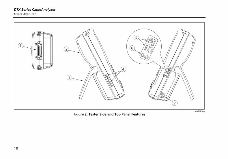
Figure 2. Tester Side and Top Panel Features

Getting Acquainted
11
A Connector for twisted pair interface adapters.
B Cover for the module bay. Slide off the cover to install optional modules, such as the fiber module.
C Bail.
D DTX-1800 and DTX-1200: Slot and activity LED for the removable memory card. To eject the card, push in then release the card.
E USB ( ) and RS-232C ( : DTX-1800, DTX-1200) ports for uploading test reports to a PC and updating the tester’s software. The RS-232C port uses a custom DTX cable available from Fluke Networks.
F Headset jack for talk mode.
G Connector for the ac adapter. The LED turns on when the tester is connected to ac power.
• Red: Battery is charging.
• Green: Battery is charged.
• Flashing red: Charge timeout. The battery failed to reach full charge within 6 hours. See “Powering the Tester” on page 14.
Figure 2. Tester Side and Top Panel Features (cont.)

DTX Series CableAnalyzer Users Manual
12
TEST
LOW BATTERY
TONE
TALK
FAIL
TEST
PASS
TALK
1
2
3
4
5
6
7
8
9 10
11
12
13
14
amd30f.eps
Figure 3. Smart Remote Features

Getting Acquainted
13
Caution All the LEDs flash if the smart remote detects excessive voltage on the cable. Unplug the cable immediately if this occurs.
Note
The LEDs also act as a battery gauge. See Figure 5 on page 15.
A Connector for twisted pair interface adapters.
B Pass LED lights when a test passes.
C Test LED lights during cable tests.
D Fail LED lights when a test fails.
E Talk LED lights when the smart remote is in talk mode. Press Oto adjust the volume.
F Tone LED lights and the tone generator turns on when you press P, but the main tester is not connected.
G Low battery LED lights when the battery is low.
H P: Starts the test currently selected on the main unit. Activates the tone generator for twisted pair cabling if no main tester is detected. The test starts when both testers are connected.
I O: Press to use the headset to talk to the person at the other end of the link. Press again to adjust the volume. Press and hold to exit talk mode.
J M: On/off key.
K USB port for updating the tester’s software with a PC.
L Headset jack for talk mode.
M Connector for the ac adapter, as described in Figure 2.
N Cover for the module bay. Slide off the cover to install optional modules, such as the fiber module.
Figure 3. Smart Remote Features (cont.)

DTX Series CableAnalyzer Users Manual
14
Powering the Tester
• You may charge the battery when it is attached or detached from the tester. Figure 4 shows how to remove the battery.
• The battery charges fully in about 4 hours with the tester off. A fully-charged battery lasts for at least 12 hours of typical use.
Note
The battery will not charge at temperatures outside of 0 °C to 45 °C (32 °F to 113 °F). The battery charges at a reduced rate between 40 °C and 45 °C (104 °F and 113 °F).
• The battery status icon ( ) near the upper-right corner of main screens shows the battery’s charge level. The smart remote’s LEDs show the smart remote’s battery status at the end of the power-up cycle, as shown in Figure 5.
For additional battery information, connect the main tester and smart remote through link adapters, turn the rotary switch to SPECIAL FUNCTIONS; then select Battery Status. See page 56 for information on retraining the battery gauge.
• If the battery does not reach full charge within 6 hours, the battery LED flashes red. Verify that the battery was within the temperature range given above during charging and that the correct ac adapter was used. Disconnect then reconnect ac power and try charging the battery again. If the battery does not charge the second time, it should be replaced.
Localizing the Tester
Local settings include Language, Date, Time, Numeric Format, Length Units, and Power Line Frequency.
1 Turn the rotary switch to SETUP.
2 Use D to highlight Instrument Settings at the bottom of the list; then press H.
3 Use Cand D to find and highlight Language on the bottom of tab 2; then press H.
4 Use D to highlight the desired language; then press H.
5 Use the arrow keys and H to find and change other local settings on tabs 2, 3, and 4 under Instrument Settings.

Getting Acquainted
15
amd32f.eps
Figure 4. Removing the Battery Pack
TEST
LOW BATTERY
TONE
TALK
FAIL
TEST
PASS
TALK
LOW BA
TONE
TALK
FAIL
TEST
PASS
0 % - 17 %
18 % - 33 %34 % - 50 %
51 % - 66 %67 % - 83 %
84 % - 100 %
amd31f.eps
Figure 5. Smart Remote Battery Status Shown After Power-Up

DTX Series CableAnalyzer Users Manual
16
About Link Interface Adapters
Link interface adapters provide the correct jacks and interface circuitry for testing different types of twisted pair LAN cabling. The channel and permanent link interface adapters provided are suitable for testing cabling up to Cat 6. Optional coaxial adapters let you test coaxial cabling.
Figure 6 shows how to attach and remove adapters.
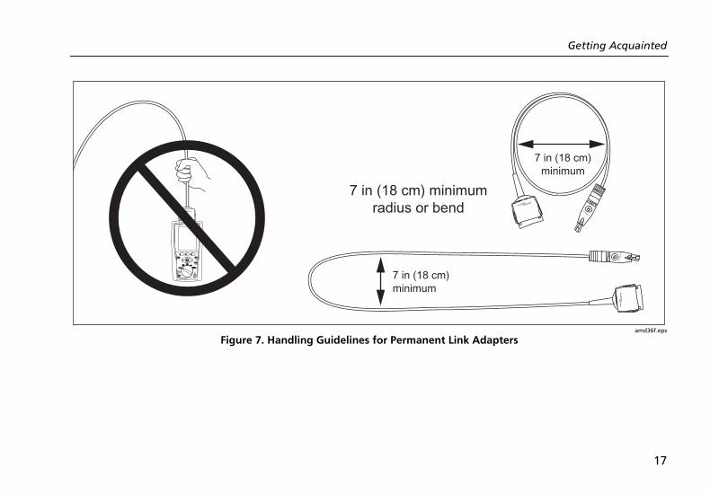
WCaution To avoid damaging the permanent link adapter and to ensure maximum accuracy of test results, never pinch, kink, or crush the adapter’s cable. Follow the handling guidelines given in Figure 7.
TALK
MONITOR
ENTER
TEST
SAVE
SPECIAL FUNCTIONS
SETUP
AUTO TESTSINGLE
TEST
EXIT
F1 F2 F3
TALK
MONITOR
ENTER
TEST
SAVE
SPECIAL FUNCTIONS
SETUP
AUTO TESTSINGLE
TEST
EXIT
F1 F2 F3
amd35f.eps
Figure 6. Attaching and Removing Adapters
Getting Acquainted
17
TALKTALK
MONITORMONITOR
ENTERENTER
TESTTEST
SAVESAVE
SPECIAL SPECIAL FUNCTIONSFUNCTIONS
SETUPSETUP
AUTO AUTO TESTTESTSINGLE SINGLE
TESTTEST
DSP-7XXX CABLE ANALYZER
EXITEXIT
F1F1 F2F2 F3F3
7 in (18 cm) minimumradius or bend
7 in (18 cm)minimum
7 in (18 cm)minimum
PM06
PM06
amd36f.eps
Figure 7. Handling Guidelines for Permanent Link Adapters

DTX Series CableAnalyzer Users Manual
18
The DTX-PLA001 universal permanent link adapter has a removable personality module. These may be changed to customize the adapter for different jack configurations.
To change the personality module, do the following (refer to Figure 8):
1 Ground yourself by touching a grounded, conductive surface.
2 Remove the link interface adapter from the tester.
3 Use your fingers to unscrew the screw on the personality module.
4 Store the module in its original, static protection bag.
5 Put the new module in place and tighten the screw with your fingers.
WCaution Tighten the screw snugly with your fingers only. Do not overtighten. Doing so can damage the module or the end of the cable.
Static sensitivedevice
Personalitymodule
TALK
MONITOR
ENTER
TEST
SAVE
SPECIAL FUNCTIONS
SETUP
AUTO TESTSINGLE
TEST
EXIT
F1 F2 F3
amd74f.eps
Figure 8. Changing the Personality Module
The optional DTX/DSP/OMNI-PLCAL automated calibration kit lets you calibrate your permanent link adapters to compensate for physical changes that occur over time to the adapter’s cable and other components. Contact Fluke Networks for more information.
Preparing to Save Tests
19
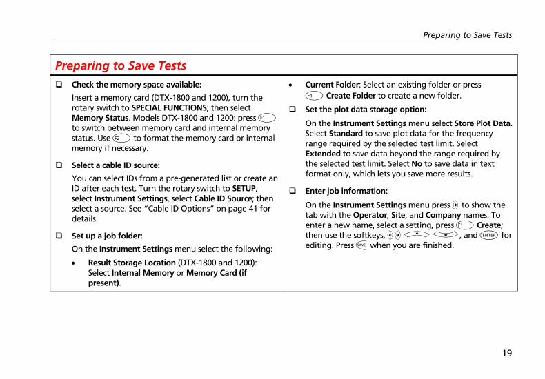
Preparing to Save Tests
! Check the memory space available:
Insert a memory card (DTX-1800 and 1200), turn the rotary switch to SPECIAL FUNCTIONS; then select Memory Status. Models DTX-1800 and 1200: press J to switch between memory card and internal memory status. Use K to format the memory card or internal memory if necessary.
! Select a cable ID source:
You can select IDs from a pre-generated list or create an ID after each test. Turn the rotary switch to SETUP, select Instrument Settings, select Cable ID Source; then select a source. See “Cable ID Options” on page 41 for details.
! Set up a job folder:
On the Instrument Settings menu select the following:
• Result Storage Location (DTX-1800 and 1200): Select Internal Memory or Memory Card (if present).
• Current Folder: Select an existing folder or press J Create Folder to create a new folder.
! Set the plot data storage option:
On the Instrument Settings menu select Store Plot Data. Select Standard to save plot data for the frequency range required by the selected test limit. Select Extended to save data beyond the range required by the selected test limit. Select No to save data in text format only, which lets you save more results.
! Enter job information:
On the Instrument Settings menu press C to show the tab with the Operator, Site, and Company names. To enter a new name, select a setting, press J Create; then use the softkeys, BC A D, and H for editing. Press N when you are finished.

DTX Series CableAnalyzer Users Manual
20
Certifying Twisted Pair Cabling Setting the Reference for Twisted Pair Cabling
The reference procedure sets a baseline for insertion loss, ELFEXT, and dc resistance measurements.
Run the tester’s reference procedure at the following times:
• When you want to use the tester with a different smart remote. You can reference the tester to two different smart remotes.
• Every 30 days. Doing so ensures maximum accuracy of test results.
You do not need to set the reference after changing link interface adapters.
Note
Turn on the tester and smart remote and let them sit for 1 minute before setting the reference. Set the reference only after the testers have reached an ambient temperature between 10 °C and 40 °C (50 °F and 104 °F).

Certifying Twisted Pair Cabling
21
To set the reference, do the following:
1 Attach permanent link and channel adapters and make the connections shown in Figure 9.
2 Turn the rotary switch to SPECIAL FUNCTIONS and turn on the smart remote.
3 Highlight Set Reference; then press H. If both a fiber module and copper adapter are attached, select Link Interface Adapter next.
4 Press P.
PM06
Permanent linkadapter
Channeladapter
TEST
LOW BATTERY
TONE
TALK
FAIL
TEST
PASS
TALKTALK
MONITOR
ENTER
TEST
SAVE
SPECIAL FUNCTIONS
SETUP
AUTO TESTSINGLE
TEST
EXIT
F1 F2 F3
amd41f.eps
Figure 9. Twisted Pair Reference Connections

DTX Series CableAnalyzer Users Manual
22
Twisted Pair Test Settings
Table 1 describes the settings that apply to twisted pair cabling tests.
To access the settings, turn the rotary switch to SETUP, use D to highlight Twisted Pair; then press H.
Table 1. Twisted Pair Test Settings
Setting Description
SETUP > Twisted Pair > Cable Type
Select a cable type appropriate for the type you will test. The cable types are organized by type and manufacturer. Selecting Custom lets you create a cable type. See the Technical Reference Handbook for details.
SETUP > Twisted Pair > Test Limit
Select the appropriate test limit for the job. Selecting Custom lets you create a test limit. See the Technical Reference Handbook for details.
SETUP > Twisted Pair > NVP
Nominal velocity of propagation, which is used with the measured propagation delay to determine cable length. The default value defined by the selected cable type represents the typical NVP for that cable type. You may enter a different value if necessary. To determine the actual value, change the NVP until the measured length matches the known length of a cable. Use a cable at least 30 m (100 ft) long.
Increasing the NVP increases measured length.
-continued-
Certifying Twisted Pair Cabling
23
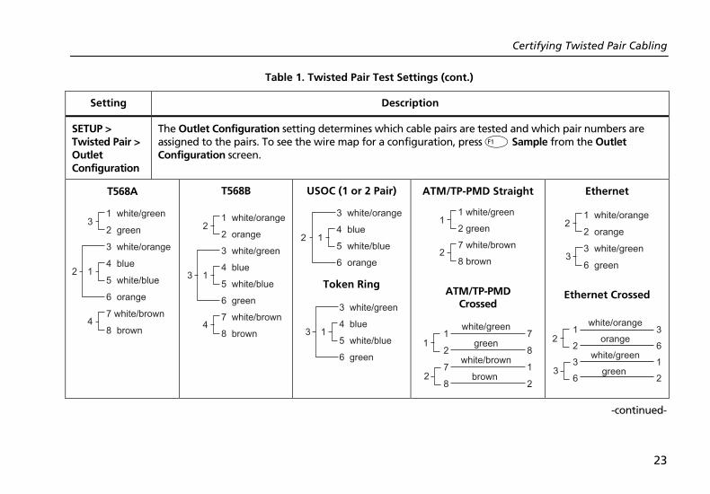
Table 1. Twisted Pair Test Settings (cont.)
Setting Description
SETUP > Twisted Pair > Outlet Configuration
The Outlet Configuration setting determines which cable pairs are tested and which pair numbers are assigned to the pairs. To see the wire map for a configuration, press J Sample from the Outlet Configuration screen.
T568A
1 white/green
2 green
3 white/orange
4 blue
5 white/blue
6 orange
7 white/brown
8 brown
12
3
4
T568B
1 white/orange
2 orange
3 white/green
4 blue
5 white/blue
6 green
7 white/brown
8 brown
13
2
4
USOC (1 or 2 Pair)
3 white/orange
4 blue
5 white/blue
6 orange
12
Token Ring
3 white/green
4 blue
5 white/blue
6 green
13
ATM/TP-PMD Straight
1 white/green
2 green
7 white/brown
8 brown
1
2
ATM/TP-PMD Crossed
2
11
2
7
8
7
8
1
2
white/green
green
white/brown
brown
Ethernet
1 white/orange
2 orange
3 white/green
6 green3
2
Ethernet Crossed
3
21
2
3
6
3
6
1
2
white/orange
orange
white/green
green
-continued-

DTX Series CableAnalyzer Users Manual
24
Table 1. Twisted Pair Test Settings (cont.)
Setting Description
SETUP > Instrument Settings > Store Plot Data
Standard: The tester displays and saves plot data for frequency-based tests such as NEXT, return loss, and attenuation. The tester saves data for the frequency range required by the selected test limit.
Extended: The tester saves data beyond the frequency range required by the selected test limit.
No: Plot data is not saved, which lets you save more results. Saved results show worst margins and worst values for each pair.
SPECIAL FUNCTIONS > Set Reference
The tester must be referenced to the smart remote the first time the two units are used together. You should also set the reference every 30 days. See “Setting the Reference for Twisted Pair Cabling” on page 20.
Settings for saving tests See “Preparing to Save Tests” on page 19.

Certifying Twisted Pair Cabling
25
Autotest on Twisted Pair Cabling
Figure 10 shows the equipment needed for certifying twisted pair cabling.
PM06
PM06
1
2
34
5TEST
LOW BATTERY
TONE
TALK
FAIL
TEST
PASS
TALKTALK
MONITOR
ENTER
TEST
SAVE
SPECIAL FUNCTIONS
SETUP
AUTO TESTSINGLE
TEST
EXIT
F1 F2 F3
amd40f.eps
A Tester and smart remote with battery packs
B Memory card (optional)
C Two ac adapters with line cords (optional)
D For testing permanent links: two permanent link adapters
E For testing channels: two channel adapters
Figure 10. Equipment for Certifying Twisted Pair Cabling

DTX Series CableAnalyzer Users Manual
26
Autotest on Twisted Pair Cabling
1 Attach adapters appropriate for the job to the tester and the smart remote.
2 Turn the rotary switch to SETUP, then select Twisted Pair. Set the following on the Twisted Pair tab:
• Cable Type: Select a list of cable types; then select the cable type to be tested.
• Test Limit: Select the test limit required for the job. The screen shows the last nine limits used. Press J More to see other lists of limits.
3 Turn the rotary switch to AUTOTEST and turn on the smart remote. Connect to the cabling, as shown in Figure 11 for a permanent link or Figure 12 for a channel.
4 If a fiber module is installed, you may need to press J Change Media to select Twisted Pair as the media type.
5 Press Pon the tester or smart remote. To stop the test at any time, press I.
Tip: Pressing Pon the tester or smart remote starts the tone generator so you can use a tone probe before connecting, if necessary. The tone also activates a sleeping or powered-down tester connected to the other end of the cabling.
6 The tester shows the Autotest Summary screen when the test is complete (see Figure 13 on page 29). To view results for a specific parameter, use A D to highlight the parameter; then press H.
7 If the Autotest failed, press J Fault Info for possible causes of the failure.
8 To save the results, press N. Select or create a cable ID; then press N again.

Certifying Twisted Pair Cabling
27
Work area
Optional consolidationpoint
Patch panel Wall outlet
Horizontal cabling
Endpermanent
link
Start permanentlink
Tester with permanentlink adapter
Smart remote withpermanent link adapter
TALK
MONITOR
ENTER
TEST
SAVE
SPECIAL FUNCTIONS
SETUP
AUTO TESTSINGLE
TEST
EXIT
F1 F2 F3
TEST
LOW BATTERY
TONE
TALK
FAIL
TEST
PASS
TALK
amd22f.eps
Figure 11. Permanent Link Test Connections

DTX Series CableAnalyzer Users Manual
28
Work area
Optional consolidationpoint
Patchpanels
Hub or switch
Wall outlet
Horizontal cabling
Endchannel
Tester withchannel adapter
Smart remote withchannel adapter
Patch cordfrom PC
Patch cordfrom hub or
switch
Startchannel
TEST
LOW BATTERY
TONE
TALK
FAIL
TEST
PASS
TALKTALK
MONITOR
ENTER
TEST
SAVE
SPECIAL FUNCTIONS
SETUP
AUTO TESTSINGLE
TEST
EXIT
F1 F2 F3
amd21f.eps
Figure 12. Channel Test Connections
Certifying Twisted Pair Cabling
29
Autotest Summary Results for Twisted Pair Cabling
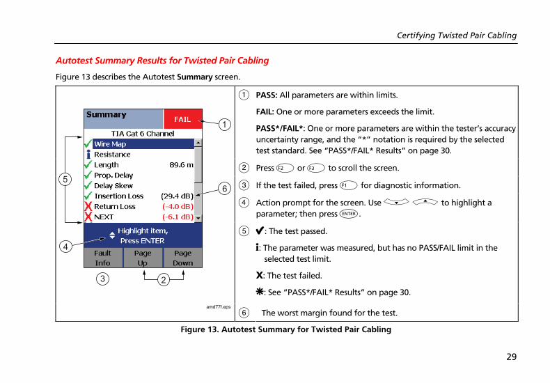
Figure 13 describes the Autotest Summary screen.
A PASS: All parameters are within limits.
FAIL: One or more parameters exceeds the limit.
PASS*/FAIL*: One or more parameters are within the tester’s accuracy uncertainty range, and the “*” notation is required by the selected test standard. See “PASS*/FAIL* Results” on page 30.
B Press K or L to scroll the screen.
C If the test failed, press J for diagnostic information.
D Action prompt for the screen. Use D A to highlight a parameter; then press H.
E E: The test passed.
i: The parameter was measured, but has no PASS/FAIL limit in the selected test limit.
X: The test failed.
U: See “PASS*/FAIL* Results” on page 30.
amd77f.eps
F The worst margin found for the test.
Figure 13. Autotest Summary for Twisted Pair Cabling

DTX Series CableAnalyzer Users Manual
30
PASS*/FAIL* Results
A result marked with an asterisk means that measurements are in the tester’s accuracy uncertainty range (Figure 14) and the “*” notation is required by the selected test standard. These results are considered marginal. Marginal passing and failing results are marked with blue and red asterisks, respectively.
For a PASS* result you should look for ways to improve the cabling installation to eliminate the marginal performance.
A FAIL* result should be considered a failure.
LimitPASS*
PASS*
FAIL*
Tester'saccuracy
uncertaintyrange
FAILFAIL*
PASS
amd42f.eps
Figure 14. PASS* and FAIL* Results

Automatic Diagnostics
31
Automatic Diagnostics If an Autotest fails, press J Fault Info for diagnostic information about the failure. The diagnostic screens show likely causes of the failure and suggest actions you
can take to solve the problem. A failed test may produce more than one diagnostic screen. In this case, press ADBC to see additional screens.
Figure 15 shows examples of diagnostic screens.
amd75f.eps
Figure 15. Examples of Automatic Diagnostic Screens

DTX Series CableAnalyzer Users Manual
32
Certifying Coaxial Cabling Certifying coaxial cabling requires the optional DTX-COAX coaxial adapters.
Setting the Reference for Coaxial Cabling
The reference procedure sets a baseline for insertion loss measurements.
Run the tester’s reference procedure at the following times:
• When you want to use the tester with a different smart remote. You can reference the tester to two different smart remotes.
• Every 30 days. Doing so ensures maximum accuracy of test results.
You do not need to set the reference after changing link interface adapters.
Note
Turn on the tester and let it sit for 1 minute before setting the reference. Set the reference only after the testers have reached an ambient temperature between 10 °C and 40 °C (50 °F and 104 °F).

Certifying Coaxial Cabling
33
To set the reference, do the following:
1 Attach coaxial adapters to the main and remote testers, screw in the F-connector to BNC adapters; then make the connections shown in Figure 16.
2 Turn the rotary switch to SPECIAL FUNCTIONS and turn on the smart remote.
3 Highlight Set Reference; then press H. If both a fiber module and copper adapter are attached, select Link Interface Adapter.
4 Press P.
TEST
LOW BATTERY
TONE
TALK
FAIL
TEST
PASS
TALKTALK
MONITOR
ENTER
TEST
SAVE
SPECIALFUNCTIONS
SETUP
AUTOTESTSINGLE
TEST
EXIT
F1 F2 F3
amd140.eps
Figure 16. Coaxial Reference Connections

DTX Series CableAnalyzer Users Manual
34
Coaxial Test Settings
Table 2 describes the settings that apply to coaxial cabling tests.
To access the settings, turn the rotary switch to SETUP, use D to highlight Coaxial; then press H.
Table 2. Coaxial Cable Test Settings
Setting Description
SETUP > Coaxial > Cable Type
Select a cable type appropriate for the type you will test. The cable types are organized by type and manufacturer. Selecting Custom lets you create a cable type. See the Technical Reference Handbook for details.
SETUP > Coaxial > Test Limit
Select the appropriate test limit for the job. Selecting Custom lets you create a test limit. See the Technical Reference Handbook for details.
SETUP > Coaxial > NVP
Nominal velocity of propagation, which is used with the measured propagation delay to determine cable length. The default value defined by the selected cable type represents the typical NVP for that cable type. You may enter a different value if necessary. To determine the actual value, change the NVP until the measured length matches the known length of a cable. Use a cable at least 30 m (100 ft) long.
Increasing the NVP increases measured length.
-continued-
Certifying Coaxial Cabling
35
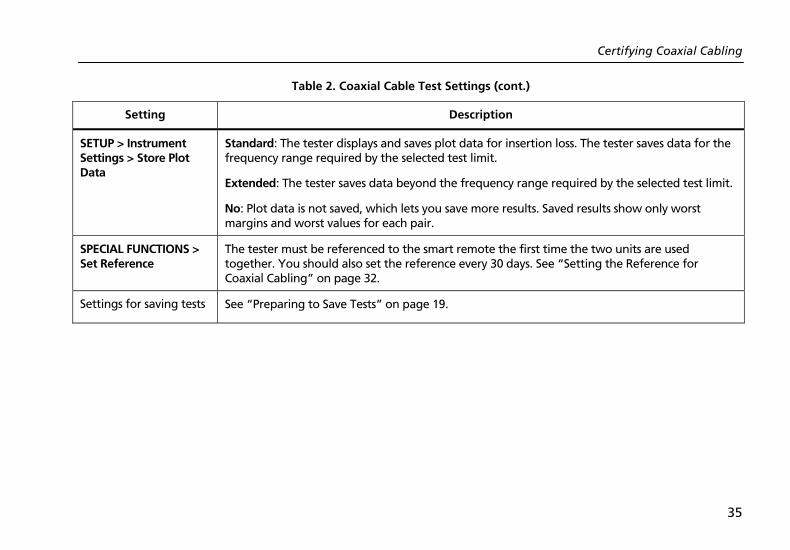
Table 2. Coaxial Cable Test Settings (cont.)
Setting Description
SETUP > Instrument Settings > Store Plot Data
Standard: The tester displays and saves plot data for insertion loss. The tester saves data for the frequency range required by the selected test limit.
Extended: The tester saves data beyond the frequency range required by the selected test limit.
No: Plot data is not saved, which lets you save more results. Saved results show only worst margins and worst values for each pair.
SPECIAL FUNCTIONS > Set Reference
The tester must be referenced to the smart remote the first time the two units are used together. You should also set the reference every 30 days. See “Setting the Reference for Coaxial Cabling” on page 32.
Settings for saving tests See “Preparing to Save Tests” on page 19.
DTX Series CableAnalyzer Users Manual
36
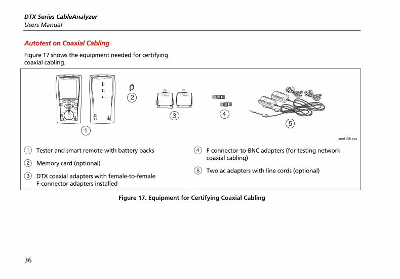
Autotest on Coaxial Cabling
Figure 17 shows the equipment needed for certifying coaxial cabling.
1
2
3 4TEST
LOW BATTERY
TONE
TALK
FAIL
TEST
PASS
TALKTALK
MONITOR
ENTER
TEST
SAVE
SPECIALFUNCTIONS
SETUP
AUTOTESTSINGLE
TEST
EXIT
F1 F2 F3
5
amd138.eps
A Tester and smart remote with battery packs
B Memory card (optional)
C DTX coaxial adapters with female-to-female F-connector adapters installed
D F-connector-to-BNC adapters (for testing network coaxial cabling)
E Two ac adapters with line cords (optional)
Figure 17. Equipment for Certifying Coaxial Cabling

Certifying Coaxial Cabling
37
Autotest on Coaxial Cabling
1 Attach coaxial adapters to the tester and smart remote.
2 Turn the rotary switch to SETUP, then select Coaxial. Set the following on the Coaxial tab:
• Cable Type: Select a list of cable types; then select the cable type to be tested.
• Test Limit: Select the test limit required for the job. The screen shows the last nine limits used. Press J More to see other lists of limits.
3 Turn the rotary switch to AUTOTEST and turn on the smart remote. Connect to the cabling, as shown in Figure 18 or 19.
4 If a fiber module is installed, you may need to press J Change Media to select Coax as the media type.
5 Press Pon the tester or smart remote. To stop the test at any time, press I.
6 The tester shows the Autotest Summary screen when the test is complete (see Figure 20 on page 40). To view results for a specific parameter, use A D to highlight the parameter; then press H.
7 To save the results, press N. Select or create a cable ID; then press N again.

DTX Series CableAnalyzer Users Manual
38
TALK
MONITOR
ENTER
TEST
SAVE
SPECIALFUNCTIONS
SETUP
AUTOTESTSINGLE
TEST
EXIT
F1 F2 F3
TEST
LOW BATTERY
TONE
TALK
FAIL
TEST
PASS
TALK
amd139.eps
Figure 18. Coaxial Network Cabling Test Connections

Certifying Coaxial Cabling
39
Female to femaleF-connector adapter
Tester with coaxialadapter
Smart remote withcoaxial adapter
TALK
MONITOR
ENTER
TEST
SAVE
SPECIAL FUNCTIONS
SETUP
AUTO TESTSINGLE
TEST
EXIT
F1 F2 F3
Connection tocoaxial cabling
Female to femaleF-connector adapter
TEST
LOW BATTERY
TONE
TALK
FAIL
TEST
PASS
TALK
Walloutlet
amd142.eps
Figure 19. Coaxial Video Cabling Test Connections

DTX Series CableAnalyzer Users Manual
40
Autotest Results for Coaxial Cabling
Figure 20 describes the Autotest Summary screen.
A
PASS: All parameters are within limits.
FAIL: One or more parameters exceeds the limit.
B E: The test passed.
i: The parameter was measured, but has no PASS/FAIL limit in the selected test limit.
X: The test failed.
amd141f.eps
C The worst margin found for the test.
Figure 20. Autotest Results for Coaxial Cabling

Cable ID Options
41
Cable ID Options You can select cable IDs from a pre-generated list or you can create an ID after each test.
To select a source for cable IDs, turn the rotary switch to SETUP, select Instrument Settings, select Cable ID Source; then select a source:
• Auto Increment: Increments the last character of the ID each time you press N.
• List: Lets you use an ID list created in LinkWare software and downloaded to the tester.
• Auto Sequence: Lets you use a list of sequential IDs generated from a template. The horizontal, backbone, and campus templates follow the ID formats specified in the ANSI/TIA/EIA-606-A standard. The Free Form template lets you create your own pattern.
• None: Lets you create an ID each time you press N.
After you press N, you can also edit an existing ID before using it for saving results.
To create a list of sequential IDs, do the following:
1 On the Auto Sequence screen, select a template.
2 On the Auto Sequence screen, select Start ID. Use the softkeys, BC A D, and H to enter the first ID in the sequential list. Press N when you are finished.
3 Select Stop ID. Use the softkeys, BC A D, and H to enter the last ID in the sequential list. Press N when you are finished
4 Press L Sample List to see what the list will look like.
Used IDs are marked with a “$” in cable ID lists.
DTX Series CableAnalyzer Users Manual
42
Memory Functions All DTX testers have internal memory that can store at least 250 Autotest results, including graphical data. The maximum capacity of internal memory depends on the space taken by the tester’s software.
The DTX-1800 and DTX-1200 testers can also store up to 500 Cat 6 Autotest results, including graphical data, on a 16 MB card. The testers can also use secure digital (SD) memory cards.
Formatting the Memory Card (DTX-1800 and DTX-1200) or Internal Memory
Formatting erases all contents of the memory card or internal memory.
To format the memory card or internal memory:
1 Turn the rotary switch to SPECIAL FUNCTIONS, then select Memory Status.
2 For a DTX-1800 or DTX-1200 with a memory card installed, press J to select the memory card or internal memory.
3 Press K Format.
Setting the Storage Location (DTX-1800 and DTX-1200)
To set the destination for saved results turn the rotary switch to SETUP, select Instrument Settings, select Result Storage Location; then select Internal Memory or Memory Card (if present).
Note
If you change the Result Storage Location, and the selected Current Folder does not exist in the new location, the tester creates a new folder with the current folder’s name in the new location.
Viewing Results
To view saved results, do the following:
1 Turn the rotary switch to SPECIAL FUNCTIONS; then select View/Delete Results.
2 If necessary, press J Change Folder to find the result you want to view.
3 Highlight the result; then press H.

Memory Functions
43
Moving and Deleting Results
DTX-1800, DTX-1200
To move or copy all results from internal memory to the memory card, turn the rotary switch to SPECIAL FUNCTIONS, select Move/Copy Internal Results; then select an option:
• Move to Memory Card: Moves all results and their folders to the memory card and deletes all results from internal memory.
• Copy to Memory Card: Copies all results and their folders to the memory card.
• Delete from Internal Memory: Deletes all results from internal memory.
All Models
To delete results or folders, do the following:
1 Turn the rotary switch to SPECIAL FUNCTIONS, then select View/Delete Results.
2 If necessary, press J Change Folder to find the results you want to delete.
3 Do one of the following:
• To delete one result, highlight it, press K Delete; then press L Delete.
• To delete all results in the current folder, in all locations, or to delete a folder, press K Delete; then select an option.
For the DTX-1200 and DTX-1800, the All Results in Tester option also deletes all results on the memory card if one is present.

DTX Series CableAnalyzer Users Manual
44
Uploading Results to a PC
To upload results to a PC, do the following:
1 Install the latest version of LinkWare software on your PC.
2 Turn on the tester.
3 Connect the tester to the PC with the USB cable included or the DTX serial cable available from Fluke Networks.
or
Insert the memory card containing results into the PC’s memory card reader.
4 Start LinkWare software on the PC.
5 Click Import on the LinkWare toolbar. Select the tester’s model from the list.
or
Select Memory card or folder on PC.
6 Select the records you want to import; then click OK.

Options and Accessories
45
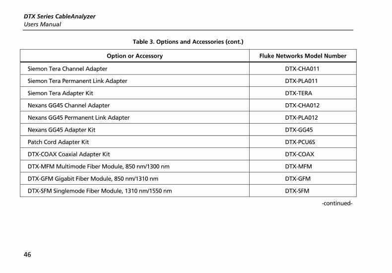
Options and Accessories Table 3 shows options and accessories available for the DTX Series CableAnalyzers. For a complete list of options and accessories visit the Fluke Networks website at www.flukenetworks.com.
To order options or accessories, contact Fluke Networks as described on page 2.
Table 3. Options and Accessories
Option or Accessory
Fluke Networks Model Number
Cat 6/Class E Channel Adapter DTX-CHA001
Cat 6/Class E Channel Adapters, set of 2 DTX-CHA001S
Universal Permanent Link Adapter DTX-PLA001
Universal Permanent Link Adapters, set of 2 DTX-PLA001S
Cat 6 Centered Personality Module DSP-PM06
Personality modules for IDC and legacy cabling systems Many models are available. Contact Fluke Networks or visit the Fluke Networks website for details.
DSP-PMxx
-continued-
DTX Series CableAnalyzer Users Manual
46
Table 3. Options and Accessories (cont.)
Option or Accessory Fluke Networks Model Number
Siemon Tera Channel Adapter DTX-CHA011
Siemon Tera Permanent Link Adapter DTX-PLA011
Siemon Tera Adapter Kit DTX-TERA
Nexans GG45 Channel Adapter DTX-CHA012
Nexans GG45 Permanent Link Adapter DTX-PLA012
Nexans GG45 Adapter Kit DTX-GG45
Patch Cord Adapter Kit DTX-PCU6S
DTX-COAX Coaxial Adapter Kit DTX-COAX
DTX-MFM Multimode Fiber Module, 850 nm/1300 nm DTX-MFM
DTX-GFM Gigabit Fiber Module, 850 nm/1310 nm DTX-GFM
DTX-SFM Singlemode Fiber Module, 1310 nm/1550 nm DTX-SFM
-continued-

Options and Accessories
47
Table 3. Options and Accessories (cont.)
Option or Accessory Fluke Networks Model Number
DTX-FTK Fiber Test Kit Fiber optic meter module and 850 nm/1300 nm SimpliFiber source. Measures power and loss at 850 nm/1300 nm (1310 nm/1550 nm with optional source).
DTX-FTK
DTX-FOM Fiber Optic Meter Module Measures power and loss at 850 nm/1300 nm and 1310 nm/1550 nm.
DTX-FOM
Permanent Link Calibration Kit DSP-PLCAL
Lithium Ion Battery Pack DTX-LION
DTX RS-232 Serial Cable (DB-9 to IEEE 1394) DTX-SER
USB Interface Cable DTX-USB
Carrying Strap DTX-STRP
Carrying Case DTX-CASE
AC Charger, North America, 120VAC DTX-ACNA
AC Charger, Universal, 120-240VAC DTX-ACUN
-continued-

DTX Series CableAnalyzer Users Manual
48
Table 3. Options and Accessories (cont.)
Option or Accessory
Fluke Networks Model Number
Headset for DSP and DTX CableAnalyzers DTX-TSET
32 MB SD Memory Card DTX-SDC32
64 MB SD Memory Card DTX-SDC64
128 MB SD Memory Card DTX-SDC128
Memory Card Reader, USB DSP-MCR-U
Memory Card Carry Case MMC CASE
IntelliTone IT100 Probe MT-8200-53A
LinkWare Cable Test Management Software (You may download this at no charge from the Fluke Networks website.)
LinkWare
LinkWare Stats Statistical Report Option LinkWare-Stats
-continued-

Options and Accessories
49
Table 3. Options and Accessories (cont.)
Option or Accessory Fluke Networks Model Number
DTX-1800 Main Unit Replacement with Battery Pack DTX-1800/MU
DTX-1800 Smart Remote Replacement with Battery Pack DTX-1800/RU
DTX-1200 Main Replacement with Battery Pack DTX-1200/MU
DTX-1200 Smart Remote Replacement with Battery Pack DTX-1200/RU
DTX-LT Main Replacement with Battery Pack DTX-LT/MU
DTX-LT Smart Remote Replacement with Battery Pack DTX-LT/RU

DTX Series CableAnalyzer Users Manual
50
About LinkWare and LinkWare Stats Software The LinkWare Cable Test Management software included with your tester lets you do the following:
• Upload test records to PC.
• View test results.
• Add ANSI/TIA/EIA-606-A administration information to records.
• Organize, customize, and print professional-quality test reports.
• Update the tester’s software.
Details about using LinkWare software are provided in the LinkWare Getting Started Guide and the online help available under Help on the LinkWare menu.
Updates to LinkWare software are available on the Fluke Networks website.
The LinkWare Stats Statistical Report option for LinkWare software provides statistical analysis of cable test reports and generates browsable, graphical reports. LinkWare software includes a demo version of LinkWare Stats. Contact Fluke Networks or visit the Fluke Networks website for more information on LinkWare Stats.

Maintenance
51
Maintenance
WX Warning To avoid possible fire, electric shock, personal injury, or damage to the tester:
• Do not open the case. No user-serviceable parts are inside.
• Replacing electrical parts yourself will void the tester's warranty and might compromise its safety features.
• Use only specified replacement parts for user-replaceable items.
• Use only Fluke Networks authorized service centers.
Caution Replacing electrical parts yourself might void the tester's calibration and compromise its accuracy. If the calibration is void, cable manufacturers might not extend their warranty to the cabling you install.
Cleaning
Clean the display with glass cleaner and a soft, lint-free cloth. Clean the case with a soft cloth dampened with water or water and a mild soap.
Caution To avoid damaging the display or the case, do not use solvents or abrasive cleansers.
Factory Calibration
The tester requires calibration at a service center once a year to ensure that it meets or exceeds the published accuracy specifications. Contact an authorized Fluke Networks Service Center for information on getting your tester calibrated.

DTX Series CableAnalyzer Users Manual
52
Updating the Tester’s Software
Keeping your tester’s software current gives you access to new features and the latest test limits.
To see the software version installed in your tester or smart remote, connect the testers through link adapters, turn the rotary switch to SPECIAL FUNCTIONS; then select Version Information.
To get a software update, download the update from the Fluke Networks website or contact Fluke Networks to get the update by other means.
Caution To avoid unexpected loss of power, connect the ac adapter to the tester when updating the software.
Note
Changes to the update procedure may be posted on the DTX CableAnalyzer software page on the Fluke Networks website.
Updating with a PC
1 Install the latest version of LinkWare software on your PC.
2 Download the DTX CableAnalyzer update file from the Fluke Networks website, or contact Fluke Networks to get the update by other means. You can access the software page at www.flukenetworks.com/support. Save the file to your hard drive.
3 Make the connections shown in Figure 21 using the USB or DTX serial cable. (The USB connection, if available, is faster.) Turn on the tester and the smart remote.
Note
The DTX serial cable connects a PC’s DB-9 RS-232 serial port to the miniature RS-232 serial port on the DTX-1800 and DTX-1200 testers. This cable is included with the DTX-1800 and is available from Fluke Networks.

Maintenance
53
4 Select Utilities > DTX Utilities > Software Update from the LinkWare menu, locate and select the .dtx (DTX update) file; then click Open.
5 When the tester is updated, it reboots, then prompts you about updating the smart remote’s software. Press K OK to update the smart remote’s software.
6 To verify the update, turn the rotary switch to SPECIAL FUNCTIONS; then select Version Information.
USB orDTX RS-232serial cable
TEST
LOW BATTERY
TONE
TALK
FAIL
TEST
PASS
TALK
TALK
MONITOR
ENTER
TEST
SAVE
SPECIAL FUNCTIONS
SETUP
AUTO TESTSINGLE
TEST
EXIT
F1 F2 F3
amd72f.eps
Figure 21. Updating the Software with a PC

DTX Series CableAnalyzer Users Manual
54
Updating with Another Tester
You can update a tester’s software using another tester that is already updated.
1 Use link interface adapters to connect an updated tester or smart remote to a tester or smart remote that needs updating (Figure 22).
Note
One of the testers must be a main tester.
2 Turn on both testers; then press Pon either. The testers compare software versions. If one has more recent software, the main tester prompts you about updating the older software.
3 Press K OK to start the update process.
4 To verify the update, turn the rotary switch to SPECIAL FUNCTIONS; then select Version Information.
PM06
TEST
LOW BATTERY
TONE
TALK
FAIL
TEST
PASS
TALKTALK
MONITOR
ENTER
TEST
SAVE
SPECIAL FUNCTIONS
SETUP
AUTO TESTSINGLE
TEST
EXIT
F1 F2 F3
PM06
TALK
MONITOR
ENTER
TEST
SAVE
SPECIAL FUNCTIONS
SETUP
AUTO TESTSINGLE
TEST
EXIT
F1 F2 F3
TALK
MONITOR
ENTER
TEST
SAVE
SPECIAL FUNCTIONS
SETUP
AUTO TESTSINGLE
TEST
EXIT
F1 F2 F3
amd73f.eps
Figure 22. Updating the Software with an Updated Tester
Maintenance
55
Updating with a Memory Card (DTX-1800, DTX-1200)
You can update the tester’s software using a memory card that contains the software update file.
1 Download the DTX CableAnalyzer update file from the Fluke Networks website, or contact Fluke Networks to get the update by other means. You can access the software page at www.flukenetworks.com/support. Save the file to your hard drive.
2 Copy the software update file to a memory card.
3 Connect the tester and smart remote together using a permanent link and a channel adapter or two channel adapters and a patch cord. Turn on the tester and the smart remote.
4 Put the memory card in the tester.
5 Turn the rotary switch to SPECIAL FUNCTIONS; then select Update Software.
6 Press L Yes to start the update procedure.
7 When the tester is updated, it reboots, then prompts you about updating the smart remote’s software. Press K OK to update the smart remote’s software.
8 To verify the update, turn the rotary switch to SPECIAL FUNCTIONS; then select Version Information.
DTX Series CableAnalyzer Users Manual
56
Retraining the Battery Gauge
The accuracy of the battery gauge may drift over time if the battery is frequently recharged before being fully discharged. Retraining the battery gauge restores its accuracy.
Retraining can take 17 to 30 hours. The time is shorter if you start with the batteries discharged and modules (such as the fiber module) installed in the main and remote testers.
To retrain the battery gauge:
1 Connect the main and remote testers together using a permanent link adapter and a channel adapter, two channel adapters or two coaxial adapters and a patch cord, or two fiber modules and two fiber patch cords.
2 Connect the ac adapters to the main and remote testers. Turn on both testers.
3 Turn the rotary switch to SPECIAL FUNCTIONS; then select Battery Status. Verify that both the main and remote battery gauges are shown. If the remote gauge is missing, check the connections between the two units.
4 Press J Train Battery.
To abort the retraining, hold down the power key (M) on the main and remote testers until they turn off.
5 Retraining is complete when the testers have turned off and the LED by the ac adapter connection is green.

Certification and Compliance
57
Certification and Compliance
; N10140
Conforms to relevant Australian standards
P Conforms to relevant European Union directives.
) Listed by the Canadian Standards Association.
CSA Standards
CAN/CSA-C22.2 No. 1010.1-92 + Amendment 2: 1997 and CAN/CSA-C22.2 No. 1010.1 2000 (2nd edition) Safety Requirements for Electrical Equipment for Measurement, Control, and Laboratory Use, Part 1: General Requirements.
Safety
CAN/CSA-C22.2 No. 1010.1-92 + Amendment 2: 1997; Overvoltage Category II, Pollution degree 2, 30 V.
EN61010, 2nd Edition, MEASUREMENT (Installation) CATEGORY I, Pollution Degree 2 per IEC1010-1 refers to the level of Impulse Withstand Voltage protection provided. Equipment of MEASUREMENT CATEGORY I is for measurements performed on circuits not directly connected to mains.

DTX Series CableAnalyzer Users Manual
58

59 59
Index
—*— * in results, 30
—A— accessories
optional, 45 standard, 4
adapters, 16 asterisk in results, 30 Auto Increment, 41 Auto Sequence, 41 Autotest
asterisk in results, 30 automatic diagnostics, 31 channel connections, 28 coaxial results, 40
permanent link connections, 27 running, 26, 37 twisted pair results, 29
—B— backbone template, 41 backlight, 9 battery
charging and status, 14 retraining the battery gauge, 56
buttons, 9
—C— cable IDs, 41 Cable Type
coaxial, 34 twisted pair, 22
calibration, 51 campus template, 41 cautions, 5, 51 channel test connections, 28 cleaning, 51 coaxial
Autotest, 37 reference, 32 results, 40 test settings, 34
connections channel, 28 permanent link, 27
connectors main tester, 11 RJ11 (telephone), 6 smart remote, 13
Custom Cable Type and Test Limit coaxial, 34
DTX Series CableAnalyzer Users Manual
60
twisted pair, 22
—D— Date, 14 deleting results and folders, 43 diagnostics, 31 display, 9
—F— FAIL*, 30 Fault Info, 31 Fluke Networks
contacting, 2 Knowledge Base, 3
folders creating, 19 deleting, 43 duplicate, 42
formatting memory, 42 front panel
main tester, 9 smart remote, 13
—H— horizontal template, 41
—I— IDs, 41
—K— keys
main tester, 9 smart remote, 13
Knowledge Base, 3
—L— language, 14 Length Units, 14 link interface adapters, 16 LinkWare (uploading results), 44 LinkWare and LinkWare Stats, 50 List, 41
—M— maintenance, 51 moving results, 43
—N— None, 41
Numeric Format, 14 NVP
coaxial, 34 twisted pair, 22
—O— options, 45 Outlet Configuration, 23
—P— PASS*, 30 permanent link
interface adapters, 16 test connections, 27
power, 14 Power Line Frequency, 14
—R— reference
coaxial, 32 twisted pair, 20
registration, 2 RJ11 connector, 6
Index (continued)
61 61
—S— safety
information, 5 standards, 57
serial cable (RS-232), 52 settings
coaxial, 34 twisted pair, 22
setup Autotest, 26, 37 battery, 14 coaxial test settings, 34 for saving tests, 19 local settings, 14 twisted pair test settings, 22
software updates, 52
with a memory card, 55 with a PC, 52 with another tester, 54
version, 52 Store Plot Data
coaxial, 35 twisted pair, 24
Summary screen coaxial, 40 twisted pair, 29
—T— talk feature, 13 talk mode, 9 template, 41 Test Limit
coaxial, 34 twisted pair, 22
Time, 14 tone generator, 26
smart remote, 13 tester, 9
twisted pair Autotest, 26 reference, 20 results, 29 test settings, 22
—U— updating the software, 52
with a memory card, 55 with a PC, 52 with another tester, 54
uploading results, 44
—V— version, 52
—W— warnings, 5, 51 wire map diagrams, 23

DTX Series CableAnalyzer Users Manual
62