Cable RF ingress measurement in an anechoic chamber -...
16
Larry Cohen Cable RF Ingress Measurement in an Anechoic Chamber August 18, 2015
Transcript of Cable RF ingress measurement in an anechoic chamber -...

Larry Cohen
Cable RFIngressMeasurement inan AnechoicChamber
August 18, 2015

8/18/2015 2
Overview
• Purpose: Propose a CMNR common-mode ingress target level based upon measuredcommon-mode and differential RF ingress levels at an MDI port termination on linksegment cabling from a controlled external RF field in an anechoic chamber
– Test data from CKC Labs 3m anechoic chamber (6/3/2008) performed by Teranetics, Inc.
– Original purpose of this test procedure was to measure RF ingress level differences betweenUTP and ScTP/STP from different vendors’ cable samples
– Use data from UTP sample to derive a proposed CMNR target level for 2.5G/5GBase-T
• Background for performing test
• Description of measurement procedure and test cases
• Summary of plots
– Vendor A Cat 6A UTP common-mode and differential mode ingress
– Vendor B Cat 6 ScTP common-mode and differential mode ingress
– Vendor C Cat 6 ScTP common-mode and differential mode ingress
– Vendor D Cat 6 STP common-mode and differential mode ingress
– Differential-to-common-mode coupling ratio for Vendor A Cat6A UTP
– Proposed CMNR calibration target levels for 2.5G/5GBase-T
• For CMNR test purposes, an important result of this contribution is that thecommon-mode ingress level should roll off with increasing frequency and shouldnot remain constant above 250 MHz as currently defined in Table 113A-2

8/18/2015 3
Background for Performing Test
• Background issues– We were using ScTP and STP cable for active data links inside the test chamber during
radiated immunity testing of 10GBase-T products to suppress RF ingress from the testchannel and isolate the external field effects to the equipment under test
– We observed some ScTP patch cords allowed RF ingress levels comparable to UTP patchcords into the test channel
• Purpose of the test procedure– Measure RF ingress level differences in ScTP (shield around all four pairs only), STP (per
pair shielded), and UTP (Cat 6A) cable samples
– Use a known calibrated external field strength (10 V/meter) near the MDI port interface sothat the measurement data can be used for in-house engineering purposes (important datafor CMNR test)
• Test setup– Very simple linear cable layout; did not use Bech rack or any complex layout geometry
– E-field is locally monitored (and calibrated) near the MDI termination test fixture RJ45 port
– Measure both common-mode and differential mode RF ingress levels for all cable samples;termination test fixture contains no magnetic components, only RJ45 connector
– Measured RF ingress from 100 MHz to 1000 MHz; could not test down to 80 MHz becauseof a power amplifier output overload (saturation) problem
• For CMNR testing, our main interest is the RF ingress measurement data fromthe Cat 6A UTP sample

8/18/2015 4
Cabling RF Ingress Measurement Procedure
• Build test setup in chamber as shown in diagram; start with 180-degree splitter on Pair A (Pins 1-2)
• Adjust output level of signal generator and amplifier so that measured E-field level is 10 V/meter;test signal is unmodulated CW (i.e. no 80% modulation at 1 kHz as used in the radiated immunitytest)
• Measure and record ingress signal level with the spectrum analyzer at each frequency point (lowerlimit was 100 MHz due to power amplifier distortion problem)
• Using GPIB control, step signal generator at from 100 MHz to 1000 MHz at 10 MHz intervals andrepeat previous three steps at each signal generator frequency (100 MHz to 1000 MHz)
• Replace the 180-degree splitter with a 0-degree splitter to measure common-mode signal ingress
• Repeat the above measurement sequence for common-mode ingress level on Pair A (Pins 1-2)
• Repeat the above test sequence for both differential and common-mode for cable Pair B (Pins 3-6)
• Repeat the entire above test sequence with different cable sample
• For final result differential-mode reference impedance is 100 W and common-mode referenceimpedance is 25 W. No level adjustment is necessary to account for splitters as they are virtuallylossless (-50 dBm 1 mV @ 100 W, 500 mV @ 25 W)
Additional data processing steps for CMNR test for 2.5G/5GBase-T
• Compute and plot differential-to-common-mode coupling ratio for Cat 6A UTP sample
• Use Cat 6A UTP common-mode measurement data to derive a CMNR common-mode target levellimit

8/18/2015 5
Setup to Measure Cable RF Ingress from an External Radiated Field
DM-CMTermination
Block
Non-conductivecable support(80 cm height)
3 meters
2 metersTest cable
RJ45 TerminationBoard inside
shielded enclosure
SpectrumAnalyzer
180-degree splitterfor differential-mode
All unused pairsterminated with 50
RJ45
50
GPIB
GPIB ControlHost PC G
PIB
0-degree splitter forcommon-mode
Balun
RF PowerAmplifier
Antenna(1 meter height)
Shielded anechoicchamber
E-field sensor(for calibration)
E-Fieldstrengthmeter
SignalGenerator50
50
GPIB GPIB
50
GPIB
50 50
PowerSplitter
50
L2
(1 to 10 meters)
Ferriteclamp
100 Differential-mode and75 Common-mode
termination for all four pairs
Ferriteclamp
8/18/2015 6
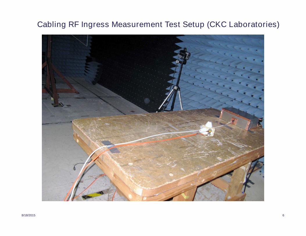
Cabling RF Ingress Measurement Test Setup (CKC Laboratories)

8/18/2015 7
Measurement Test Cases
• Test cables– No cable attached to termination box (measurement noise floor)
– Vendor A Cat 6A UTP (10 meters)
– Vendor B Cat 6 ScTP (50 feet); screened around all four pairs, not shielded per pair
– Vendor C Cat 6 ScTP (10 meters); screened around all four pairs, not shielded perpair
– Vendor D Cat 6 STP (10 meters); screened around all four pairs and shielded per pair
• Plot only horizontal antenna polarization (dominant orientation)
• Total exposed cable length of 2 meters; 1.3 meters in fixed horizontalconfiguration– Simulate approximate length of cable exposed during CISPR 24 radiated immunity
test (in a small chamber); note exposed length would be longer in a 10 meterchamber
• Measured both differential-mode and common-mode ingress voltage
• Measured only pairs A (pins 1-2) and B (pins 3-6) for each cable sample
• For final result differential-mode reference impedance is 100 W and common-mode reference impedance is 25 W.

August 18, 2015 8

August 18, 2015 9

August 18, 2015 10

August 18, 2015 11

August 18, 2015 12
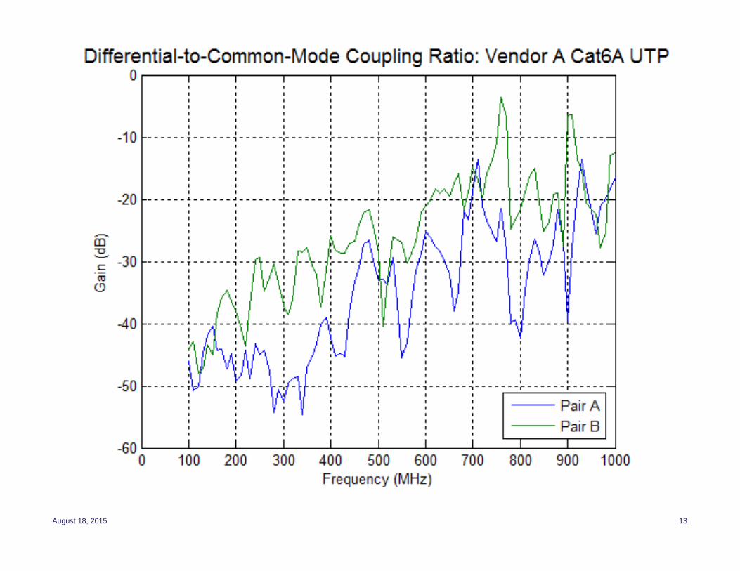
August 18, 2015 13

8/18/2015 14
Derivation of CMNR Common-Mode Ingress Limits
• Important data is the common-mode RF ingress level as this component isgenerally independent of cabling category/class
• Limit line derivation for 10 MHz to 1000 MHz (intended for 802.3bz)– Draw a limit line across the maxima of the measured (Cat 6A) UTP common-mode data
from 80 MHz to 1000 MHz
– Add 2 dB constant offset for change of reference impedance from 25 Ohms(measurement data) to 75 Ohms (used in CMNR test for UTP, 802.3bz); +2dB shift fromempirical observation of corresponding coupling change with the CC clamp
– Extend the limit line value at 80 MHz down to 30 MHz (constant value)
– For 10 MHz to 30 MHz, use the rolloff currently defined in Table 113A-2, but shift the resultso that the value at 30 MHz matches the proposed limit line at 30 MHz
– Shift the limit line down ~10.4 dB forn the corresponding equivalent ingress levels for3V/meter
– Note values on the graph plot are dBm in Vrms, but and VCM(f) below is Vpp
Vpp, f is in MHz
10008010795.0
8030795.0
301030
795.001.0
920808.0
f
f
ff
fVf
CM

August 18, 2015 15

8/18/2015 16
Summary, Discussion Points, Next Steps
• Proposed CMNR CM target levels (measured during clamp validation step) frommeasured RF ingress levels in an anechoic chamber with a 10 V/meter external fieldnear the MDI port
– This result is from a set of data points using a simple and common cable configuration
• While the common-mode target limit line in this contribution may not be adopted,an important observation from this contribution is that the common-mode ingresslevel should roll off with increasing frequency and should not remain constantabove 250 MHz as currently defined in Table 113A-2
– High-frequency rolloff likely due to re-radiation into space of received RF ingress signal(scattering); greater effect at higher frequencies and at points on the cable farther from the MDIport
– Most RF ingress from “received” signals (field-to-cable coupling) near the MDI port termination– Rolloff characteristic may change in the presence of “slack loops” or other unusual cable layout
geometries (e.g. Bech rack), especially if the unusual feature is located near the MDI port
• Screened cables are NOT alike in RF ingress performance– Vendor B Cat 6 ScTP was no better than Cat6A UTP above 100 MHz (differential signal ingress)– Performance differences due to differences in outer shield coverage and connector termination
(full 360-degree for good ScTP cables, pigtail for bad ScTP cable)
• Should the CMNR test adopt a common-mode ingress target level equivalent to a3V/meter external field or a 10V/meter external field ?
– Most 10GBase-T testing with UTP used 3V/meter, but some customers wanted specificfrequencies tested at 10V/meter; at 10V/meter the test pass criterion may be different
– Annex 113A specifies the test channel as maximal insertion loss within link segment specification
• Need to derive a corresponding differential mode RF ingress limit