Trunking - Cable tray - Cable ladder - Enclosure stainless steel

www.hdmann .c om
Cable Tray • Instrumentation Tray • Accessories
FRP Solutions for Cable Management Systems
cable management system
HDMANN
www.hdman
n.com

Welcome to HDMANN.
This product catalog and guide provides the information you need to design your cable management solution. Should you need additional information feel free to contact us at [email protected].
Please also visit our website at www.hdmannn.com
Thank you for your interest in HDMANNcable tray systems. We look forward to working with you.
HDMANN
www.hdman
n.com

4 www.hdmann.com
Qu
ick Find
Ind
ex
Ladder Cable Tray Ladder Cable Tray Fittings
Ladder Cable TrayAccessories
Support Systems& Strut
Channel-TypeInstrumentation Tray
Channel-TypeInstrumentation Tray & Fittings
Flat Cover
Inside & Outside90° Vertical Molded
Radius BendsHorizontal
Adjustable Bend45° thru 135°
Cover HoldDown Clamp
Drop Out
InstrumentSupport Stands
45° HorizontalMolded Radius
Bend
Flanged-Type Instrumentation Tray
Ladder Cable TraySplice Plates
Fastener & Hanger Systems
Qu
ick
Fin
d I
nd
ex
HDMANN
www.hdman
n.com
Quick Find Indexcable management systemHDMANN

5
This illustration is for parts visualization only and does not represent an actual layout. Not all parts are pictured here.
Blind Endpage 25
Straight Sectionspages 8-9
Outside Vertical Adjustable Molded
Radius Bendpage 15
Divider Strippage 25
Mitered RightHand Reducer
page 19
30° JoiningVertical Molded
Bendspage 14
Splice Platepage 21
Channel Framing & Support Systems with Fastener &
Hanging Systemspage 35-39
Horizontal MoldedRadius Cross
page 15
Lay-In Wirewaywith Cover
page 31
Peaked VentilatedLift Off Cover
page 23
ExpansionSplice Plate
page 21
Horizontal MoldedRadius Tee
page 15
Push ButtonSupport Stand
page 41
Qu
ick Find
Ind
ex
www.hdmann.com
Quick Find Indexcable management systemHDMANN
HDMANN
www.hdman
n.com

6
53 53 hcni rep VK ,lio ni mret trohs ,htgnertS cirtcelE
Electric Strength, short term in oil, 1�8”, vpm
Dissipation Factor, 60 Hz. (ASTM D150)* 0.03 0.03 Arc Resistance, seconds (ASTM D495)** 120 120
(ASTM D149)* 200 200
Dielectric Constant, 60 Hz.(ASTM D150)* 5.6 5.2 000,52 000,02 ISP ,htgnertS evisserpmoC
01 x ISP ,yticitsalE fo suludoM 6 2.5 3.0 000,52 000,02 ISP ,htgnertS elisneT
(FTMS 406-2023) 75/75 75/75
EV-RF P-RF )nopuoc( lacinahceM
Flammability Test
Flame Resistance, ign/burn, seconds
Intermittent Flame Test, rating (HLT-15) 100 100
(ASTM E84)
average time of burning 5 seconds, average extent of
burning 15mm (ASTM D635)
51 51 mumixam ,scitsiretcarahC gninruB ecafruS
Fire Retardant Properties
Concentric Static Load (if required)
We =2 x (Concentrated Static Load)
span length (ft or m)
A concentrated static load is not included in the table on page 9. Some user applications may require that a given concentrated static load be imposed over and above the working load. Such concentrated static load represents a static weight applied be-tween the side rail at midspan. When so speci� ed, the concentrated static load may be converted to an equivalent load (We) in pounds per linear foot (kg/m) using the formula to the below right and added to the static weight of cable in the tray. This combined load may be used to select a suitable load/span designation (table on page 9).
Flexural Modulus, PSI x 106 1.6 2.0 Flexural Modulus, PSI x 106 0.8 1.0
Ultimate Tensile Strength, PSI (ASTM D638) 30,000 35,000 Ultimate Tensile Strength, PSI 7,000 10,000 Ultimate Compressive Strength, PSI (ASTM D695) 30,000 35,000 Ultimate Compressive Strength, PSI 15,000 20,000
EV-RF P-RF )nopuoc( lacinahceM EV-RF P-RF )nopuoc( lacinahceM
Ultimate Flexural Strength, PSI (ASTM D790) 30,000 35,000 Ultimate Flexural Strength, PSI 10,000 14,000 Tensile Modulus, PSI x 106 2.5 3.0 Tensile Modulus, PSI x 106 0.8 1.0 Compressive Modulus, PSI x 106 2.5 2.5 Compressive Modulus, PSI x 106 1.0 1.2
Ultimate Shear Strength, PSI 5,500 7,000 Ultimate Shear Strength, PSI 5,500 6,000 Ultimate Bearing Stress, PSI 30,000 35,000 Ultimate Bearing Stress, PSI 30,000 35,000 Izod Impact Strength, Ft.-Lbs. per inch of notch Izod Impact Strength, Ft.-Lbs. per (ASTM D256) (sample thickness 1�8” 25 30 inch of notch (ASTM D256) 4 5 except 1�4 05 05 57-3852D MTSA( ssendraH locraB )dor rof ”
noitceriD esrevsnarTnoitceriD lanidutignoL
Typical Properties of Structural FRP
Thermal Contraction & Expansion
175°F (79°C) 59 (17) 45 (13) 23 (6)
25°F (-4°C) 417 (126) 320 (97) 162 (49) 50°F (10°C) 208 (63) 160 (48) 81 (25) 75°F (24°C) 138 (42) 106 (32) 54 (16)
Temp. Fiberglass Steel Aluminum
100°F (38°C) 104 (32) 80 (24) 40 (12) 125°F (52°C) 83 (25) 63 (19) 32 (10) 150°F (66°C) 69 (21) 53 (16) 26 (8)
Ft. (m) Ft. (m) Ft. (m) Differential
EV-RF P-RF )nopuoc( lacinahceM
Electrical
Sq. Ft./Ht./°F/In. (ASTM C-177-76) 4 4
Thermal Coefficient of Expansion Inches/Inch/°F (ASTM D696)** 5 x 10⁻⁶ 5 x 10⁻⁶
Thermal Conductivity, BTU per
Specific Heat, BTU/Lb./°F 0.28 0.28
Thermal
Mechanical (coupon) FR-P FR-VE
(24 hour immersion) (ASTM D570) .50 .50
Density, Lbs./In.3 (ASTM D792) 0.065 0.065 Specific Gravity (ASTM D792) 1.80 1.80 Water Absorption, Max. % by weight
Other
Mechanical (coupon) FR-P FR-VE
Full Section in Bending
EV-RF P-RF )nopuoc( lacinahceM
The table to the right compares the thermal contraction and expansion based on various temperature differen-tials for � berglass, steel and aluminum cable trays. The values shown represent the length of cable tray that will produce a 5�8” movement between expansion connectors for the indicated temperature differential. Fiberglass has the least movement. Enduro has expansion connectors to provide for total movement of 5�8”.
If the combined load exceeds the working load shown, please contact us. This data was obtained from the NEMA and NEC Standards Publications and other sources to assist in the proper selection of the most appropriate cable tray type offered by Enduro.
Note: 1 PSI = 6.894 K Pa; 1 Ft.-Lb./In. = 5.443 kg-m/m; * Specimen tested perpendicular to laminate face ** Indicates reported value measured in logitudinal direction; Depending on the specific glass content and resin, the strength and stiffness properties may be significantly higher. Contact us for specific values on Halogen-Free Low Smoke Plus resin properties.
Fiberglass vs Steel vs Aluminum
Tech
nic
al D
ata
www.hdmann.com
FRP Technical Datacable management systemHDMANN
HDMANN
www.hdman
n.com

7
Effect of Temperature - FRP
100°F (38°C) 90% 100%
75°F (24°C) 100% 100%
Polyester Vinyl Ester
125°F (52°C) 78% 100%
Strength % Strength %
175°F (79°C) 60% 90%
150°F (66°C) 68% 90% 200°F (93°C) 52% 75%
Temp.
Flex. St., PSI, ASTM D790 101,500 86,400 79,500 72,300 68,100 66,300 58,700 27,400 13,200 9,200 Flex. Mod., PSI x 106, ASTM D790 3.36 3.32 3.42 3.38 3.24 3.29 3.07 1.98 0.98 0.83 Tensile St., PSI, ASTM D638 84,100 70,400 63,900 58,000 56,100 54,600 49,900 41,800 29,600 22,000
Test Temp. °F (°C) -100° -50° 0° 50° 77° 100° 150° 200° 250° 300° (-73°) (-46°) (-18°) (10°) (25°) (38°) (66°) (93°) (121°) (149°)
Corrosion Resistance of Resin Systems
Hdmann has two standard resin systems available. For most applications, isophthalic polyester fire-retardant (FR-P) is the more widely used. A vinyl ester composite � re-retardant resin system (FR-VE) is recommended where strong acids (such as hydro-chloric acid), strong alkalies (such as caustic soda), organic solvents and halogenated organic conditions exist. An abbreviated guide is provided below to assist in the selection of the proper resin system for individual application.
Polyester and vinyl ester resin systems are available in conductive formulation. Contact us for corrosion resistance information for halogen-free and halogen-free low smoke plus resins.
All composite materials have an ultra-violet light inhibiting chemical additive and has a maximum � ame spread of 25 or less, per ASTM E-84 (Class 1 � ame spread). All pultruded products have complete Nexus Veil Coverage (outer surfacing fabric) to provide maximum chemical and UV protection.
Calcium Chloride FR-P FR-P Phosphoric Acid 30% FR-P FR-P
Acetic Acid 5% FR-P FR-P Magnesium Chloride FR-P FR-P Acetic Acid 25% FR-P FR-VE-210° (*) Methyl Alcohol 10% FR-P FR-VE-150° (*)
P-RF P-RF ahthpaN P-RF P-RF %5 etafluS muissatoP munimulA
Chemicals 75°F (24°C) 160F° (71°C) Chemicals 75°F (24°C) 160°F (71°C)
Ammonium Hydroxide 10% FR-P FR-VE-150° Nitric Acid 5% FR-P FR-P Ammonium Nitrate FR-P FR-P Nitric Acid 20% FR-VE FR-VE-120° (*) Benzenesulfonic Acid 5% FR-P FR-P Phosphoric Acid 10% FR-P FR-P
Ethylene Glycol FR-P FR-P Sodium Hypochlorite 5% FR-P FR-VE-120° (*)
Carbon Tetrachloride FR-VE FR-VE-100° (*) Phosphoric Acid 85% FR-P FR-P Chlorine Dioxide 15% FR-P FR-VE-150° (*) Sodium Bicarbonate 10% FR-P FR-P Chromic Acid 5% FR-P FR-VE-150° (*call) Sodium Bisulfate FR-P FR-P Copper Sulfate FR-P FR-P Sodium Carbonate FR-P FR-VE Diesel Fuel No. 1 FR-P FR-P Sodium Chloride FR-P FR-P Diesel Fuel No. 2 FR-P FR-P Sodium Hydroxide 1-50% FR-VE FR-VE-120° (*)
Ferrous Sulfate FR-P FR-P Sodium Silicate FR-P FR-VE-210° (*) Fatty Acids 100% FR-P FR-P Sodium Nitrate FR-P FR-P
P-RF P-RF dellitsiD ,retaW
Fluosilicic Acid 0-20% FR-VE FR-VE (call) Sodium Sulfate FR-P FR-P Hydrochloric Acid 1% FR-P FR-P Sulfuric Acid 0-30% FR-P FR-P Hydrochloric Acid 15% FR-P FR-VE-180° (*) Sulfuric Acid 30-50% FR-VE FR-VE Hydrochloric Acid 37% FR-P FR-VE-150° (*) Sulfuric Acid 50-70% FR-VE FR-VE-180° (*) Hydrogen Sulfide FR-P-140° FR-VE-210° Trisodium Phosphate 25% FR-P FR-VE-210° (*)
)*( °012-EV-RF EV-RF llA - etahpsohP muidosirT P-RF P-RF enesoreK
FR = Fire-Retardant; P = Polyester Resin; VE = Vinyl Ester Resin; (*) = Not recommended to exceed this temperature; call = Call for recommendationsInformation contained in this chart is based on data from raw material suppliers and collected from several years of actual industrial applications. Temperaturers are not the minimum nor the maximum (except where speci� cally stated) but represent standard test conditions. The products may be suitable at higher temperatures, but individual test data should be required to establish such suitability. The recommendations or suggestions contained in this chart are made without guarantee or representation as to results. We suggest that you evaluate these recommendations and suggestions in your own laboratory or by actual � eld trial prior to use.
Strength properties of reinforced plastics are reduced when continuously ex-posed to elevated temperatures. Working loads shall be reduced when based on the table to the right. Percentages shown are approximate. If unusual temperature conditions exist, please contact us for consultation. Below freez-ing temperatures do not adversely affect the load rating capability of the tray. Fiberglass does not become brittle at below freezing temperatures. Careful review should be made of applications involving service temperatures over 200°F.
The test values in the chart below were obtained from tests conducted by Enduro’s vinyl ester resin supplier. The values shown, although obtained from an actual coupon test, are intended for illustrative purposes only, and not for use in design calculations. The values for polyester are slightly lower.
Techn
ical Data
www.hdmann.com
FRP Technical Datacable management systemHDMANN
HDMANN
www.hdman
n.com

8
Imperial Straight Section Part NumbersExample: ELL3 - 06 - 06 - 20 - MR
Solid bottom available upon request. Rung connections are made with a mechanical and chemical lock. See speci� cation page 12, item 5.1.2 for details. Please contact us for any other custom modi� cations. 18.5” rung spacing not available for 30” and 36” widths
System No. Width Spacing Length Rung gnuR turtS = RS .tF 01 = 01 ”6 = 60 ”6 = 60
gnuR eniraM = RM .tF 02 = 02 ”52.9 = 90 ”9 = 90 gnuR eniraM = 2RM ”21 = 21 ”21 = 21
”5.81 = 81 ”81 = 81 ”42 = 42
”03 = 03 ”63 = 63
Rung
every other
See Ladder Cable Tray Selection Guide Below
1” (25mm)
1�4” (6mm)
LOA
DIN
G D
EPTH
SID
E R
AIL
HEI
GH
T
FLANGE WIDTH
Metric Straight Section Part NumbersExample: ELL3 - 150 - 150 - 6M - MR
Solid bottom available upon request. Rung connections are made with a mechanical and chemical lock. See speci� cation page 12, item 5.1.2 for details. Please contact us for any other custom modi� cations. 470mm rung spacing not available for 750mm and 900mm widths
System No. Width Spacing Length Rung 150 = 150mm 150 = 150mm 3M = 3m SR = Strut Rung 225 = 225mm 235 = 235mm 6M = 6m MR = Marine Rung 300 = 300mm 300 = 300mm MR2 = Marine Rung 450 = 450mm 470 = 470mm 600 = 600mm 750 = 750mm 900 = 900mm
Rung
every other
See Ladder Cable Tray Selection Guide Below
System Diagrams
Sel
ecti
on G
uid
e
Ladder Cable Tray Selection Guide
ELL3
ETL4
EHL4
ETL6
ELL6
EHL6
D-EHL6
EHZ6
EHL8
D-EHL10
8A
8A
12A
18A
20A
20B20C
20C
20C
20C
30C
1.5
1.5
1.5
1.5
2.0
2.01.5
2.0
2.0
1.5
2.0
EL(∆)3
ET(∆)4
EH(∆)4
ET(∆)6
EL(∆)6
EH(∆)6
D-EH(∆)6
EHZ(∆)6
EH(∆)8
D-EH(∆)10
-
-
-
Class A
Class C
Class C
-
Class C
-
Class A
StandardSystem No.(polyester resin)
OptionalSystem No.
(∆) = insert code; see bottom of pg.
Side Rail HeightIn. (mm)*
Loading DepthIn. (mm) In. (mm)
FlangeWidth
NEMAClassFG-1
SafetyFactor
Listing
(∆) = Insert one of the following letters for resin designation * (mm) value is nominalContact us for lead times on all Halogen-Free systems.
1” (25mm)
1�4” (6mm)
LOA
DIN
G D
EPTH
SID
E R
AIL
HEI
GH
T
FLANGE WIDTH EHZ6
ELL3 EHL6ETL4 D-EHL6EHL4 EHL8ETL6 D-EHL10ELL6
V = Vinyl Ester; S = Halogen-Free Polyester; VS = Halogen-Free Vinyl Ester; Y = Halogen-Free Low Smoke Plus; RT = Conductive
In. (mm)
Min. Channel Thickness
3” 113/ /
/
/
/
/
/
/
/
/
/
/ /
/ /
/ /
/ /
/ /
/ /
/ /
/ /
/
16” 1” 3 16 ” (75) (46) (25) (4.8)
4” 278 ” 13
8” 1 4 ” (100) (73) (35) (6.4)
4” 234” 11
8” 1 4 ” (100) (70) (28) (6.4)
6” 41316” 15
8” 5 32 ” (150) (122) (41) (4.0)
6” 41316” 15
8” 316 ”
(150) (122) (41) (4.8)
6” 434” 15
8” 14 ”
(150) (121) (41) (6.4)
6” 41116” 15
8” 516 ”
(150) (119) (41) (8.0)
6” 41116” 2” 5
16 ” (150) (119) (51) (8.0)
8” 61116” 13
4” 516 ”
(200) (170) (44) (8.0)
10” 858” 23
4” 38 ”
(250) (219) (70) (9.5)
www.hdmann.com
Ladder Cable Tray Selection Guidecable management systemHDMANN
HDMANN
www.hdman
n.com

9
Isophthalic Polyester
This industrial-grade polyester resin system offers very good weathering performance (resistance to UV) and corrosion resistance. This system is especially suitable for seawater environments.
Vinyl Ester This resin system also delivers good weathering performance, but is superior to a polyester with respect to corrosion resistance and high heat environments. Epoxy vinyl ester resins provide greater toughness and con-siderably higher strength at elevated temperatures. They also provide superior resistance to chemical attack in corrosive chemical service.
Resin SystemsBelow is an overview of the common resin systems we offer. When choosing a resin type for your application, we highly rec-ommend consulting with us regarding the application to be sure the proper resin is specif i ed. Considerations include corrosion environment, temperature, f ire resistance, smoke and smoke toxicity requirements and conductivity / resistivity requirements. Regarding the corrosion environment, certain chemical concentrations and temperatures will dictate whether a polyester or epoxy vinyl ester system is preferred for optimum durability.
Conductive This Isophthalic Polyester-based resin is formulated to comply with ABS requirements for conductivity. To pro-vide superior resistance to chemical attack, the conductive formulation is also available in a Vinyl Ester base.
Halogen-FreePolyester
This system offers similar performance attributes as our standard Isophthalic Polyester, but without the use of halogens.
Halogen-Free Low Smoke Plus
This modi� ed-acrylic based resin is suitable for applications which require extremely low-smoke development in the case of � re. This resin system is commonly used in tunnel applications.
Halogen-FreeVinyl Ester
This system offers similar performance attributes as our Vinyl Ester, but without the use of halogens.
Selection
Gu
ide
Tray WeightLbs/Ft. (kg/m)
2 side rails, 12” rung spacing
Working (Allowable) Load Lbs./Ft. (kg/m)8’
(2.4m)10’
(3m)12’
(3.7m)14’
(4.3m)16’
(4.9m)18’
(5.5m)20’
(6.1m)30’
(9.1m)
The Hdmann straight sections listed above that are UL Listed are for 10 Ft. and 20 Ft. lengths. All molded and mitered � ttings associated with these tray types are also UL listed. NEMA classes and UL listings in this table are for polyester and vinyl ester resin systems only. Values in Working (Allowable) Load are applicable to all resin systems, where possible. For more tray weight values, please contact us. For CSA class, please contact us.
1.97 50 (2.93) (74)
2.56 50 (3.81) (74)
3.06 224 176 134 103 76 50 (4.55) (333) (262) (199) (153) (113) (74)
2.94 243 168 124 94 50 (4.37) (361) (251) (184) (141) (74)
2.94 200 139 100 78 61 50 (4.37) (298) (207) (149) (116) (90) (74)
4.47 200 156 123 100 (6.66) (298) (232) (183) (148)
4.94 200 156 123 100 (7.34) (298) (232) (183) (148)
4.79 200 156 123 100 (7.13) (298) (232) (183) (148)
6.45 156 123 100 (9.60) (232) (183) (148)
9.39 277 225 100 (13.98) (412) (335) (148)
www.hdmann.com
Quick Find Indexcable management systemHDMANN
HDMANN
www.hdman
n.com

10
The installation of Hdmann Cable Tray should be made in compliance with the standards set forth by the Na-tional Electric Code and NEMA Publications FG-1 (cur-rent issue). Enduro supplies made to order, pre-fabri-cated cable ladder tray and f i ttings as specif i ed by the purchaser.
Always observe common safety practices when assem-bling tray and f i ttings in the f i eld. Assemble in well-ventilated areas as dust from f i eld cuts can accumu-late. This presents no serious health hazard but can cause skin irritation and, if allowed to accumulate with grease and other machining lubricants, can become abrasive. Personnel should wear safety goggles, dust mask, coveralls or a shop coat when sawing, machin-ing and/or sanding. Caution should also be noted when cutting as dust from carbon f i ber is also electrically conductive and additional considerations apply.
Avoid generating excessive heat in any machining op-eration, as heat softens the bonding resin in the f i ber-
WARNING! CABLE TRAYS ARE NOT DESIGNED FOR USE AS WALKWAYS
Reference NEMA FG-1 (current issue)In as much as f i berglass cable tray is designed as a support for power or control cables, or both; it is not intended or designed to be a walkway for person-nel. The user is urged to display appropriate warn-ing cautioning against the use of this support as a walkway.
Actual Size Label
Installation
glass, resulting in a ragged rather than a clean-cut edge.
Avoid excessive pressure when sawing, drilling, rout-ing, etc. Use carbide-tipped drill bits and saw blades for extended tool life.
The use of lubricant during machining is not recom-mended.
To avoid chipping of material at cut edges, secure cable tray and f i ttings properly during f i eld cut operations. We recommend the use of Enduro sealant for sealing surfaces and cut edges after f i eld cuts are made.
When using adhesives, be sure to prepare the sur-face properly before applying. Follow label instructions carefully. A combination of mechanical fasteners and adhesives make the strongest most reliable connec-tions.
Correct
Incorrect
Support Location Guidelines*
Inst
alla
tion
* These guidelines apply when using standard splice plates. For location � exibility, heavy duty splice plates (pg. 22) allow for support location anywhere in the span.
www.hdmann.com
Quick Find Indexcable management systemHDMANN
HDMANN
www.hdman
n.com
11
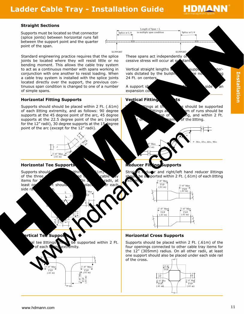
Straight Sections
Supports must be located so that connector (splice joints) between horizontal runs fall between the support point and the quarter point of the span.
Standard engineering practice requires that the splice joints be located where they will resist little or no bending moment. This allows the cable tray system to act as a continuous member with spans working in conjunction with one another to resist loading. When a cable tray system is installed with the splice joints located directly over the support, the previous con-tinuous span condition is changed to one of a number of simple spans.
These spans act independently of each other and ex-cessive stress will occur at substantially less loading.
Vertical straight lengths should be supported at inter-vals dictated by the building structure not exceeding 24 Ft. on centers.
A support should be located 2 Ft. on each side of an expansion connection.
Horizontal Fitting SupportsSupports should should be placed within 2 Ft. (.61m) of each � tting extremity, and as follows: 90 degree supports at the 45 degree point of the arc, 45 degree supports at the 22.5 degree point of the arc (except for the 12” radii), 30 degree supports at the 15 degree point of the arc (except for the 12” radii).
Vertical Fitting SupportsVertical � ttings at the top runs should be supported at each end. Fittings at the bottom of runs should be supported at the top of the � tting, and within 2 Ft. (.61m) of the lower extremity of the � tting.
Horizontal Tee SupportsSupports should be placed within 2 Ft. (.61m) of each of the three openings connected to other cable tray items for 12” (305mm) radius. On all other radii, at least one support should also be placed under each side rail of the tee.
Reducer Fitting SupportsStraight reducer and right/left hand reducer � ttings should be supported within 2 Ft. (.61m) of each � tting extremity.
Vertical Tee SupportsVertical tee � ttings should be supported within 2 Ft. (.61m) of each � tting extremity.
Horizontal Cross SupportsSupports should be placed within 2 Ft. (.61m) of the four openings connected to other cable tray items for the 12” (305mm) radius. On all other radii, at least one support should also be placed under each side rail of the cross.
Splice at L/4
SUPPORTSUPPORT
Splice at L/4Length of Span = L
in multiple span condition
2’-0” Max(.61 m)
2’-0”
Max
(.61 m
)
30∞, 45∞, 90∞1/2ø ø
2’-0” Max(.61 m)
30∞, 45∞, 60∞, 90∞
ø
ø
ø
2’-0” MaxTYP
2’-0”M
axTY
P
TYP
2/3 R
1/2 LL
2’-0” MaxTYP 2’-0” Max
TYP
2’-0” MaxTYP
2’-0” MaxTYP
(.61 m) (.61 m)
(.61 m)
(.61 m)
2’-0” Max
TYP(.61 m)
2’-0” MaxTYP
(.61 m)
TYP2/3 R2’-0” Max
TYP(.61 m)
2’-0
” M
axTY
P(.6
1 m
)
2’-0” MaxTYP
(.61 m)
Installation
www.hdmann.com
Ladder Cable Tray - Installation Guidecable management systemHDMANN
HDMANN
www.hdman
n.com

12
Cab
le Tray
4.2 All composite material shall have an ultraviolet light inhibiting chemical additive to resist UV degradation.4.3 All composite material shall be f i re retardant and have a f i ame spread rating of 25 or less (Class 1 Rating) when tested in accordance with ASTM E-84.4.4 All pultruded products shall have a complete surfacing veil to provide maximum chemical and UV protection.5.0 Construction5.1 Straight section tray shall be f i berglass reinforced meeting all the requirements herein described. 5.1.1 The side rail members must turn in. 5.1.2 All rung to side member connections shall have both a mechanical and a chemical (adhesive) lock. The tray shall be assembled by the use of a locking pin made of f i berglass reinforced thermoplastic. The locking pin shall be inserted under pressure with a high strength, chemical resistant adhesive. 5.1.3 All bonded connections must be sanded to maximize adhesion and structural integrity. 5.1.4 The tray interior shall be clear of all projections or sharp objects. 5.1.5 All straight section lengths shall be pre-drilled to accept connector plates. 5.1.6 All cut ends and drilled holes (factory and � eld) shall be resin coated.5.2 Fittings are to be pre-fabricated and shall meet all the requirements herein described. 5.2.1 All f i ttings shall have a nominal 9.25” rung spacing. 5.2.2 All f i ttings shall be pre-drilled to accept connector plates. 5.2.3 All f i ttings shall be designed and installed so as to have the same load carrying capacity as the straight sections. 5.2.4 Rung to side member connections shall have both a mechanical and/or chemical (adhesive) lock. Fittings shall be assembled by use of a locking pin made of f i berglass reinforced thermoplastic and/or a stainless steel rivet. The locking pin shall be inserted under pressure with a high strength chemical resistant adhesive. • All radius 90° and 45° horizontal and vertical bends, all tees and crosses for tray types using 6” (152mm), and most 4” (101mm) and 8” (202mm), C-channel members shall be of concentric curved molded design and made by resin transfer molding.5.3 Connector Plates and Fasteners: 5.3.1 Connector plates shall be f i berglass and designed with suff i cient strength so they may be installed between 0.2 and 0.3 of the length of the span from the support without derating the load carrying capacity of the tray. 5.3.2 Fasteners for connector plates shall be 3/8” (9.5mm) diameter Type 316 Stainless Steel, Monel, Silicon, Bronze, or FRP studs & hex nuts as required.5.4 Accessories 5.4.1 The manufacturer shall be capable of providing all necessary parts (i.e. clamps, support assemblies, etc.) for the installation of a complete f i berglass tray system.
1.0 Scope1.1 The cable tray system shall conform to the material and fabrication requirements as per this speci� cation.2.0 Standards2.1 The cable tray system shall conform to applicable sections of: 2.1.1 NEMA Standard FG-1 (latest edition) 2.1.2 National Electric Code (NEC) 2.1.3 ASTM E-84 (Class 1 Rating) 2.1.4 UL (Underwriters Laboratories, Inc.) Standards for Non-Metallic Cable Trays. 2.1.5 CSA INTERNATIONAL (National Standard of Canada) CAN/CSA-C22.2 No. 126 Cable Tray Systems3.0 General3.1 Tray Requirements 3.1.1 Tray widths 6” (152mm), 9” (229mm), 12”(305mm), 18” (457mm), 24” (610mm), 30” (762mm), and 36” (914mm) 3.1.2 Lengths (as required): 10 ft, 20 ft, 3m, and 6m 3.1.3 Rung spacing (as required): 6” (152mm), 9.25” (235mm), 12” (305mm), and 18.5” (470mm) Rung Type (as required): Standard Rung, Marine Rung or Strut Rung 3.1.4 Radius of f i ttings (as required): 12” (305mm), 24” (610mm), and 36” (914mm) 3.1.5 Resin Systems (as required): Isophthalic Polyester, Vinyl Ester, Halogen-Free Polyester, Halogen-Free Vinyl Ester, Phenolic, or Halogen-Free Low Smoke Plus3.2 Loading Requirements 3.2.1 There shall be three working load classif i cations of f i berglass cable tray based on 20 Ft. (6m) support span:
3.2.2 Span support criteria shall be as speci� ed (Reference the following table)
• Independent test reports in conformance to NEMA FG-1 are required.
3.2.3 Nominal loading depth (as required): 2” (51mm), 3” (76mm), 5” (127mm), 7” (178mm) and 9” (229mm)4.0 Materials4.1 The glass f i ber to resin content shall be maintained between 45 to 55 percent by weight in all pultruded components except f i at sheet which shall be 35 to 45 percent; and, 25 to 45 percent by weight in all molded components.
B 75 Lbs./Lineal Ft. 1.5 A 50 Lbs./Lineal Ft. 1.5 Class Working Load FOS
C 100 Lbs./Lineal Ft. 1.5
10 200 - -
20 50 75 100
30 - - 100
Working Load in Lbs./Lineal Ft.
18 61 92 123
Class A Class B Class C
14 100 150 200
16 78 117 156 12 139 208 -
SupportSpan (Ft.)
Sp
eci�
cat
ion
www.hdmann.com
Quick Find Indexcable management systemHDMANN
HDMANN
www.hdman
n.com

13
Halogen-Free Low Smoke Plus LY IY HY YZ
Halogen-Free LS IS HS HSZ
Vinyl Ester LV IV HV VZ
Conductive LRT IRT HRT -
Polyester LL IL HL MZ
8LHE 3LLE 6ZHE 01LHE-D 6LIE 6LLE
Pre-assembled mitered f i ttings are available for all tray types. Fittings are assembled using 316 SS fasteners unless specif i ed otherwise. When connecting to molded f i ttings or straight sections, expansion splice plates are recommended. For conductive and halogen-free low smoke plus cable tray, splice plates must be stain-less steel. Rung connections are made with a mechanical and/or chemical lock (see specif i cation, pg. 12, item 5.2.4). For assistance with other sizes and widths including 10” mitered f i ttings, please contact us.Listings & ApprovalsUL: All the following mitered fi ttings are UL listed in 4”, 6”, and 8” in Polyester/Vinyl Ester.
* In Part No. Key, parentheses ( ) = insert corresponding option code; H = Side Rail Height; ∆ = Resin; R = Radius; W = Width of the inside distance from tray wall to tray wall; ** Contact us for availability of 3” (76mm)
90° Horizontal Bend
Part No. Key*EHB-(∆)(H)-90-(W)-(R) 6 335/8 471/2 455/8 641/2 575/8 811/2
(152) (854) (1207) (1159) (1638) (1464) (2070)
12” (305) Radius 24” (610) Radius 36” (914) Radius
Width A L A L A L
Dimension Inches (mm)
9 365/8 513/4 485/8 683/4 605/8 853/4 (229) (930) (1314) (1235) (1746) (1540) (2178) 12 395/8 56 515/8 73 635/8 90 (305) (1006) (1422) (1311) (1854) (1616) (2286) 18 455/8 641/2 575/8 811/2 695/8 981/2 (457) (1159) (1638) (1464) (2070) (1768) (2502) 24 515/8 73 635/8 90 755/8 107 (610) (1311) (1854) (1616) (2286) (1921) (2718) 30 575/8 811/2 695/8 981/2 815/8 1153/8 (762) (1464) (2070) (1768) (2502) (2073) (2931) 36 635/8 90 755/8 107 875/8 1237/8 (914) (1616) (2286) (1921) (2718) (2226) (3146)
R
A
R
W
L
90° Vertical Inside Bend
Part No. Key*EIV-(∆)(H)-90-(W)-(R) ”8 ”6 ”4 ”8 ”6 ”4
92 L 1/2 291/2 291/2 461/2 461/2 461/2 )1811( )1811( )1811( )947( )947( )947(
02 A 7/8 207/8 207/8 327/8 327/8 327/8 )538( )538( )538( )035( )035( )035(
suidaR ”63 suidaR ”42 suidaR ”21 Dim.
Inches(mm)
Depth** Depth** ”8 ”6 ”4
36 5/16 635/16 635/16 )8061( )8061( )8061(
44 5/8 445/8 445/8 )3311( )3311( )3311(
Depth**A
R
W
L
Imperial Mitered Fittings Part NumbersExample: EHB - HL6 - 90 - 24 - 24
Type of Fitting Tray Type/Resin (∆) Height (H) Angle Width (W) Radius (R) EHB = Horizontal Bend 3 = 3” 30 = 30° 6 = 6” 12 = 12” EIV = Vertical Inside 4 = 4” 45 = 45° 9 = 9” 24 = 24” EOV = Vertical Outside 6 = 6” 60 = 60° 12 = 12” 36 = 36” EHT = Horizontal Tee 8 = 8” 90 = 90° 18 = 18” EHC = Horizontal Cross 10 = 10” 24 = 24” EVT = Vertical Tee 30 = 30” ER = Right Reducer 36 = 36”
recudeR tfeL = LE ESR = Straight Reducer EHBD = Horiz. Direct Bend
Side Rail
For vertical tee specify “up” or “down” at end of part codeCovers = EC before catalog number; example EC-EHB-MC6-90-24-24. Fasteners for covers are separate order item, see page 39.Strut Rung = SR after part number; example EHB-MC6-90-24-24-SRMarine Rung = MR after part number; example EHB-MC6-90-24-24-MR
See Selection Tableto the Right
Metric Mitered Fittings Part NumbersExample: EHB - HL6 - 90 - 600 - 600
Type of Fitting Tray Type/Resin (∆) Height* (H) Angle Width (W) Radius (R) EHB = Horizontal Bend 3 = 75mm 30 = 30° 150 = 150mm 300 = 300mm EIV = Vertical Inside 4 = 100mm 45 = 45° 225 = 225mm 600 = 600mm EOV = Vertical Outside 6 = 150mm 60 = 60° 300 = 300mm 900 = 900mm EHT = Horizontal Tee 8 = 200mm 90 = 90° 450 = 450mm EHC = Horizontal Cross 10 = 250mm 600 = 600mm
mm057 = 057 eeT lacitreV = TVE mm009 = 009 recudeR thgiR = RE
recudeR tfeL = LE ESR = Straight Reducer EHBD = Horiz. Direct Bend
Side Rail
* (mm) value is nominalFor vertical tee specify “up” or “down” at end of part codeCovers = EC before part number; example EC-EHB-MC6-90-600-600. Fasteners for covers are separate order item, see page 39.Strut Rung = SR after part number; example EHB-MC6-90-600-600-SRMarine Rung = MR after part number; example EHB-MC6-90-600-600-MR
See Selection Tableto the Upper Right
ResinEHL4EHL6
Tray Type (see page 8)
Tray Type/ResinSelection Table
Mit
ered
Fit
tin
gs
Look at left column to select resin, then look at top row to select tray type. Then, insert corresponding letters into � tting part no.
www.hdmann.com
Mitered Fittings - Ladder Cable Tray cable management systemHDMANN
HDMANN
www.hdman
n.com

14
A W
90° Vertical Outside Bend
Part No. Key*EOV-(∆)(H)-90-(W)-(R)
”8 ”6 ”4 ”8 ”6 ”4
82 L 1/8 3015/16 333/4 451/16 4715/16 503/4 )9821( )8121( )5411( )758( )687( )417(
91 A 7/8 217/8 237/8 317/8 337/8 357/8 )119( )068( )018( )606( )555( )505(
suidaR ”63 suidaR ”42 suidaR ”21 Dim.
Inches(mm)
Depth** Depth** ”8 ”6 ”4
26 1/16 647/8 673/4 )1271( )8461( )6751(
34 7/8 457/8 477/8 )6121( )5611( )4111(
Depth**
AR
WL
90° Horizontal Direct Bend
Part No. Key*EHBD-(∆)(H)-90-(W)
)604( 61 )922( 9
)033( 31 )251( 6
)mm( sehcnI snoisnemiD
)384( 91 )503( 21
Horizontal Adjustable Bend 45°-135°
Part No. Key*EHAB-(∆)(H)-(W)
30°, 45°, 60° Horizontal Direct Bend
Part No. Key*EHBD-(∆)(H)-30/45/60-(W)
6 141/16 311/2 17 30 193/16 279/16 (152) (357) (800) (432) (762) (487) (700)
30° Angle (ø) 45° Angle (ø) 60° Angle (ø)
Width A L A L A L
Dimension Inches (mm)
9 171/16 33 20 321/16 223/16 303/16 (229) (433) (838) (508) (814) (564) (767) 12 201/16 341/2 23 341/4 253/16 323/4 (305) (510) (876) (584) (870) (640) (832) 18 269/16 395/16 293/4 403/16 32 397/16 (457) (675) (999) (756) (1021) (813) (1002) 24 329/16 425/16 363/4 447/16 38 445/8 (610) (827) (1075) (933) (1129) (965) (1133) 30 389/16 455/16 413/4 4811/16 44 497/8 (762) (979) (1151) (1060) (1237) (1118) (1267) 36 449/16 485/16 473/4 5215/16 50 551/16 (914) (1132) (1227) (1213) (1345) (1270) (1399) A
ø
W
L
The 60° � tting is fabri-cated with the horizontal adjustable splice plates. Please contact us for other 30°/60° radius mitered � ttings.
45° Horizontal Bend
Part No. Key*EHB-(∆)(H)-45-(W)-(R)
6 2011/16 387/8 241/4 473/8 273/4 557/8 (152) (525) (987) (616) (1203) (705) (1419)
12” (305) Radius 24” (610) Radius 36” (914) Radius
Width A L A L A L
Dimension Inches (mm)
9 2311/16 41 271/4 491/2 303/4 58 (229) (602) (1041) (692) (1257) (781) (1473) 12 2611/16 431/8 301/4 515/8 333/4 601/8 (305) (678) (1095) (768) (1311) (857) (1527) 18 3211/16 473/8 361/4 557/8 393/4 643/8 (457) (830) (1203) (921) (1419) (1010) (1635) 24 3811/16 515/8 421/4 601/8 453/4 685/8 (610) (983) (1311) (1073) (1527) (1162) (1743) 30 4411/16 557/8 481/4 643/8 513/4 7213/16 (762) (1135) (1419) (1226) (1635) (1314) (1846) 36 5011/16 601/8 541/4 685/8 573/4 771/16 (914) (1287) (1527) (1378) (1743) (1467) (1957)
Joining 45° Horizontal BendX = 2A - .707 (W + .5)Y = 2L - .707 (W + .5)
AW
L
R
R
A
W
A
L (Varies)
W1’4”
(406)
* In Part No. Key, parentheses ( ) = insert corresponding option code; H = Side Rail Height ∆ = Resin; R = Radius; W = Width of the inside distance from tray wall to tray wall; ** Contact us for availability of 3” (76mm)
)787( 13 )016( 42
)536( 52 )754( 81
)049( 73 )267( 03 )2901( 34 )419( 63
Mitered
Fitting
s
www.hdmann.com
Ladder Cable Tray - Mitered Fittings cable management systemHDMANN
HDMANN
www.hdman
n.com

15
L 2611/16 2611/16 2611/16 249/16 249/16 249/16 (678) (678) (678) (624) (624) (624)
193/16 209//16 22 2711/16 291/16 301/2 361/8 379/16 39 (487) (522) (559) (703) (738) (775) (918) (954) (991) **
30°/45° Vertical Outside Direct Bend
Part No. Key*EOVD-(∆)(H)-30 or 45-(W)
4” 6” 8” 4” 6” 8”
A 103/16 1115/16 1311/16 123/8 1313/16 153/16 (259) (303) (348) (314) (351) (386)
30° Angle (ø) 45° Angle (ø)Dim.
Inches(mm)
Depth** Depth** ”8 ”6 ”4 ”8 ”6 ”4
92 L 1/2 291/2 307/8 267/8 267/8 2715/16 )017( )386( )386( )487( )947( )947(
11 A 13/16 139/16 161/16 1411/16 161/16 185/8 )374( )804( )753( )804( )443( )003(
( elgnA °03 ø) 45° Angle (ø)Dim.
Inches(mm)
Depth** Depth**
30°/45° Vertical Inside Direct Bend
Part No. Key*EIVD-(∆)(H)-30 or 45-(W)
30°/45° Vertical Inside Bend
Part No. Key*EIV-(∆)(H)-30 or 45-(W)-(R)
30°/45° Vertical Outside Bend
Part No. Key*EOV-(∆)(H)-30 or 45-(W)-(R)
17 17 18 18 23 23 24 24 29 29 30 30 (432) (432) (457) (457) (584) (584) (610) (610) (737) (737) (762) (762) L
7 8 10 10 9 10 12 12 11 12 14 14 (178) (203) (254) (254) (229) (254) (305) (305) (279) (305) (356) (356)
3” 4” 6” 8” 3” 4” 6” 8” 3” 4” 6” 8”
12” Radius 24” Radius 36” Radius Depth Depth Depth
30°
45°
Dim.Inches(mm)
A
A
L
103/4 123/4 143/4 145/16 165/16 185/16 1713/16 1913/16 2113/16 (273) (324) (375) (364) (414) (465) (452) (503) (554) **
18 18 18 18 24 24 24 24 30 30 30 30 (457) (457) (457) (457) (610) (610) (610) (610) (762) (762) (762) (762) L
8 9 10 12 9 10 12 14 11 12 14 15 (203) (229) (254) (305) (229) (254) (305) (356) (279) (305) (356) (381)
3” 4” 6” 8” 3” 4” 6” 8” 3” 4” 6” 8”
12” Radius 24” Radius 36” Radius Depth Depth Depth
30°
45°
Dim.Inches(mm)
A
A
L 197/8 197/8 197/8 283/8 283/8 283/8 367/8 367/8 367/8 (505) (505) (505) (721) (721) (721) (937) (937) (937)
111/16 121/2 137/8 149/16 16 177/16 181/8 191/2 2015/16 (281) (318) (352) (370) (406) (443) (470) (495) (532)
A
R
W
L
A
RW
L
A
øW
L15” (381mm)
13.5”
(343m
m)
A
ø
W
L 15”(381mm)
16.75
”(42
5mm)
Straight Reducer
Part No. Key*ESR-(∆)(H)-(W1)x(W2)
6 431/2 401/2 371/2 341/2 263/4 263/8 (152) (1105) (1029) (953) (876) (679) (670)
W1 Inches (mm)
36 (914) 30 (762) 24 (610) 18 (457) 12 (305) 9 (229)
9 42 39 36 33 263/8 (229) (1067) (991) (914) (838) (670) 12 401/2 371/2 36 263/4 (305) (1029) (953) (914) (679) 18 371/2 353/4 263/4 (457) (953) (908) (679) 24 353/4 263/4 (610) (908) (679) 30 263/4 (762) (679)
Dimension “L” Inches (mm)
W2
Inch
es (
mm
)
W1
W2
L
* In Part No. Key, parentheses ( ) = insert corresponding option code; H = Side Rail Height; ∆ = Resin; R = Radius; W = Width of the inside distance from tray wall to tray wall; ** Contact us for availability of 3” (76mm)
All dimensions are to the nearest 1/4”
All dimensions are to the nearest 1�4”
**
**
**
**
**
**
**
**
**
**
Mit
ered
Fit
tin
gs
www.hdmann.com
Mitered Fittings - Ladder Cable Tray cable management systemHDMANN
HDMANN
www.hdman
n.com

16
* In Part No. Key, parentheses ( ) = insert corresponding option code; H = Side Rail Height; ∆ = Resin; R = Radius; W = Width of the inside distance from tray wall to tray wall
Right or Left Hand Reducer
Part No. Key*RIGHT: ER-(∆)(H)-(W1)x(W2)
LEFT: EL-(∆)(H)-(W1)x(W2) 6 551/2 461/4 461/4 37 37 273/4 (152) (1410) (1175) (1175) (940) (940) (705)
W1 Inches (mm)
36 (914) 30 (762) 24 (610) 18 (457) 12 (305) 9 (229)
9 461/4 461/4 37 37 273/4 (229) (1175) (1175) (940) (940) (705) 12 461/4 37 37 273/4 (305) (1175) (940) (940) (705) 18 37 37 273/4 (457) (940) (940) (705) 24 37 273/4 (610) (940) (705) 30 273/4 (762) (705)
Dimension “L” Inches (mm)
W2
Inch
es (
mm
)
W1
W2L
6 305/8 551/2 425/8 74 545/8 1013/4 (152) (780) (1410) (1080) (1880) (1390) (2580)
12” (305) Radius 24” (610) Radius 36” (914) Radius
Width A L A L A L
Dimension Inches (mm)
9 335/8 551/2 455/8 831/4 575/8 1013/4 (229) (850) (1410) (1160) (2110) (1460) (2580) 12 365/8 551/2 485/8 831/4 605/8 111 (305) (930) (1410) (1240) (2110) (1540) (2820) 18 425/8 643/4 545/8 921/2 665/8 111 (457) (1080) (1640) (1390) (2350) (1690) (2820) 24 485/8 74 605/8 921/2 725/8 1201/4 (610) (1240) (1880) (1540) (2350) (1840) (3050) 30 545/8 74 665/8 1013/4 785/8 1291/2 (762) (1390) (1880) (1690) (2580) (2000) (3290) 36 605/8 831/4 725/8 111 845/8 1291/2 (914) (1540) (2110) (1840) (2820) (2150) (3290)
Horizontal Tee
Part No. Key*EHT-(∆)(H)-(W1)-(W2)-(R)
Horizontal Cross
Part No. Key*EHC-(∆)(H)-(W1)-(W2)-(R)
6 543/4 551/2 783/4 74 1023/4 1013/4 (152) (1390) (1410) (2000) (1880) (2610) (2580)
12” (305) Radius 24” (610) Radius 36” (914) Radius
Width A L A L A L
Dimension Inches (mm)
9 573/4 551/2 813/4 831/4 1053/4 1013/4 (229) (1470) (1410) (2080) (2110) (2690) (2580) 12 603/4 551/2 843/4 831/4 1083/4 111 (305) (1540) (1410) (2150) (2110) (2760) (2820) 18 663/4 643/4 903/4 921/2 1143/4 111 (457) (1700) (1640) (2310) (2350) (2910) (2820) 24 723/4 74 963/4 921/2 1203/4 1201/4 (610) (1850) (1880) (2460) (2350) (3070) (3050) 30 783/4 74 1023/4 1013/4 1263/4 1291/2 (762) (2000) (1880) (2610) (2580) (3220) (3290) 36 843/4 831/4 1083/4 111 1323/4 1291/2 (914) (2150) (2110) (2760) (2820) (3370) (3290)
W1W2
L
A
R
R
W2L A
RR
W1
Right hand reducer is shown
Vertical Tee
Part No. Key*EVT-(∆)(H)-90-(W)-(R)
54 63 7/8 853/4 )8712( )5611( )419(
33 42 7/8 613/4 )8651( )068( )016(
)mm( sehcnI snoisnemiD
Radius L A
L
A
RR
Specify “up” or “down” at the end of the part no.
Mitered
Fitting
s
www.hdmann.com
Ladder Cable Tray - Mitered Fittings cable management systemHDMANN
HDMANN
www.hdman
n.com

17
Ladder Cable Tray Splice Plate Part NumbersExample: ESP - 6C - 180
Hdmann offers a full line of f i berglass splice plates designed to provide a structural transition between straight sections and f i ttings. Enduro splice plates and hardware are sold separately and are not provided as standard with straight sections or f i ttings due to the many hardware options. All plates have 7/16” pre-drilled bolt holes.
* For Horiz. and Vert. Adjustable part number use “ESP” for Type, example: ESP-6C-HA. Expansion plates have 1” slotted holes allowing 5/8” total con-traction and expansion. Refer to thermal contraction table on page 6 for maximum spacing between expansion joints. Side rail height of 3” and 4” comes with 4 bolt sets per plate. Side rail height of 6” and 8” comes with 8 bolt sets per plate. Side rail height of 10” comes with 12 bolt sets per plate. For 6” and 8” channel heavy duty splice plates, see page 22.
NEMA FG-1Please refer to NEMA FG-1 regarding proper tray installation as it pertains to support and splice plate locations for straight sections and fi ttings. Refer to page 11 for recommended support locations.
Type Height Material Degree ESP = Straight 3 = 3” (76mm) C = Polyester 180 = Straight, Expansion EEP = Expansion 4 = 4” (102mm) V = Vinyl Ester 90 = 90° EVS = Vertical 6 = 6” (152mm) SS = Stainless Steel 45 = 45°
°03 = 03 )mm302( ”8 = 8 latnoziroH = SHE °5.22 = 5.22 )mm452( ”01 = 01
*elbatsujdA .ziroH = AH *elbatsujdA .treV = AV
Side Rail
Splice and Hardware Options
Polyester Standard Optional Optional Standard Optional Optional Optional
steS erawdraH lairetaM ecilpS
Polyester Vinyl Ester Steel Steel Monel Silicon Bronze Isoplast
Vinyl Ester Standard Optional Standard Optional Optional Optional Halogen-Free Standard Standard Optional Optional Optional Halogen-Free Low Smoke Plus Conductive Standard Standard Optional Optional Optional
316 Stainless 316 Stainless
Hardware
Typical Dimensions for FRP Splice Plates
3 (76) 13/4 (44) 1 (25) -0-
6 (152) 45/8 (117) 1 (25) 25/8 (67)
4 (102) 2 (51) 1 (25) -0-
A B CChannelDepthInches(mm)
Typical Dimensions Inches (mm)
8 (203) 6 (152) 111/16 (43) 25/8 (67)
Typical Dimensions for Stainless Splice Plates
1 )67( 3 1/4 (32) 5/8 (16) -0-
4 )251( 6 1/8 (105) 3/4 (19) 25/8 (67)
1 )201( 4 1/4 (32) 5/8 (16) -0-
C B A ChannelDepthInches(mm)
Typical Dimensions Inches (mm)
4 )302( 8 1/8 (105) 3/4 (19) 25/8 (67)
Standard Standard Optional Optional Optional
316 Stainless Steel Bolt Set Bolt, nut, 2 flat washers, 1 lock washer 3/8”-16 x 11/4” All tray types (except 10” Channel**)
Type Set Includes Size For Use With Tray Types
316 Stainless Steel Bolt Set Bolt, nut, 2 flat washers, 1 lock washer 3/8”-16 x 11/2” All tray types (except 10” Channel**) Monel Bolt Set Bolt, nut, 2 flat washers, 1 lock washer 3/8”-16 x 11/4” All tray types (except 10” Channel**) FRP Studs & Nuts Stud and 2 nuts 3/8”-16 x 2” ELL3, ELL4, ELL6, EIL6, EMZ6
Silicon Bronze Bolt Set Bolt, nut, 2 flat washers, 1 lock washer 3/8”-16 x 11/4” All tray types (except 10” Channel**)
FRP Studs & Nuts Stud and 2 nuts 3/8”-16 x 21/2” EHL6, EHL8, EHV6
** Contact us for hardware; It is recommended that expansion splice plates and 11�4” long assembly fasteners be used when connecting mitered fittings to molded fittings or straight lengths.
Tray ResinSp
lice
Pla
tes
Part No.505167SS505168SS606167M707166F707167F
808167SB
www.hdmann.com
Quick Find Indexcable management systemHDMANN
HDMANN
www.hdman
n.com

18
Straight Section lacitreV °09noisnapxEnoitceS thgiartS
lacitreV °5.22lacitreV °03lacitreV °54
Adjustable Vertical 90° Horizontal 45° Horizontal
30° Horizontal 22.5° Horizontal Adjustable Horizontal
BC
A
83/4”(222)
21/8”(54)
11/4”(32)
41/4”(108) 63/8”
(162)
7/16” (11)hole
7/16” x 1” (11 x 25)
slot
45/8”(117)
107/8”(276)
Field Drilling Required
B
C
A
21/8”(54)
11/4”(32)
47/8”(124)
7/16” (11)hole
45°
30° 22.5°
51/16”(129)
1”(25)
1”(25)
45/8”(117)
63/8”(162)
21/8”(54)
7/16” x 1”(11 x 25)slot, typ.
25/8”(67)
57/16”(138)
A
B
21/8”(54)
11/4”(32)
C
57/16”(138)
22.5°
45°
11/
www.hdmann.com
Quick Find Indexcable management systemHDMANN
4”(32)
A
B
47/8”(124)
21/8”(54)
C
7/16” (11)hole
30°
6”(152)
Sp
lice Plates
HDMANN
www.hdman
n.com

19
21/8”(54)
21/8”(54)
21/8”(54)
21/8”(54)
21/8”(54)
21/8/”(54)
21/8”(54)
11/4”(32)
1/16”+_A
7/16” (11) ø
171/4” (438)
1/16”+_B
25/8” (67)
21/8”(54)
21/8”(54)
21/8”(54)
21/8”(54)
21/8”(54)
21/8”(54)
21/8”(54)
11/4”(32)
23/4” (70)stock
171�4” (438)
Heavy Duty Splice Plates
Part No. Key*ESP-(H) HP-180 Splice Plate
Part No. Key*EEP-(H) HP-180 Splice Plate
1 )721( 5 )251( 6 3/8 (35) 3 )201( 4 (76) 13/8 (35)
6 )402( 8 3/8 (162) 21/16 (52)
B A Side RailHeightInches(mm)
Inches(mm)
Inches(mm)
10” Channel Splice Plates
Part No.ESP-10C-180 Splice Plate
Part No.EEP-10C-180 Splice Plate
* In Part No. Key, parentheses ( ) = insert corresponding option code; H = Side Rail Height - 4, 6, 8 (inches)
Sp
lice
Pla
tes
13” (330)
21/8” (54)4 Plcs.
211/16” (68)
25/8” (67)
C8 x 13/4” x 5/16”
11/4” (32)21/8” (54)7/16” (11) Dia. 12 Plcs. 7/16” (11) x 1” Slot 12 Plcs.
11/4” (32)21/8” (54)
13” (330)
21/8” (54)4 Plcs.
13/4” (44)
8” (204)
5/16” (7.9)
2” (50.8)2” (50.8)
www.hdmann.com
Splice Plates - Ladder Cable Traycable management systemHDMANN
HDMANN
www.hdman
n.com

20
Resin Designation
Hdmann offers a full line of accessories for our electrical products including cable tray covers, divider strips, drop outs, blind ends, adapters, hold-down clips, marine rungs, strut rungs, swivel clamps and a wide variety of stainless steel or FRP cable tray fasteners appropriate for any application.
(∆) = Insert one of the following letters for resin designations when required.
Clampless Flat Cover
Part No. Key*EPC-CL-(W)-(∆)
Cable tray covers are recommended for those areas where the cable needs protection from falling objects, adverse weather conditions, etc. Available in 10ft. (3m) sections in both � at and peaked design. In addition to cover, solid bottom is also available. See page 24 for cover accessories.
Easiest & Lowest Installation Cost
Eliminates the need for Hold Down Clamp for a quicker and easier � eld installation. Recommended to be purchased with a cable tray straight section matching the clampless f i at cover section.
A total of three pairs of stainless embedded nuts are pre-installed to the cable tray channels by Enduro. Contact us for metal types available on embedded nuts. 1/4” diameter stainless fasteners and � at washers are also included and shipped separately.
Contact us regarding f i ttings availability on this type of cover system.
Available tray widths (inches): 6, 9, 12, 18, 24, 30, 36
Stainless embedded nut pre-installed by Enduro
Flat Cover
Part No. Key*“C” Tray: E(∆)C-(W)
“Z” Tray: EZC-(W)
Installation Methods for Flat Cover: Thermo-plastic Drive Rivets (part no. R-25) are the most economical method, but do require f i eld drilling.
It is recommended rivets be installed on 24” centers along both side rails.
Cover Hold Down Clamps and Enduro Stand Offs allow cover to be removed for easy access to cables - see page 24.
It is recommended to use seven pair at 1’6” on center per 10 Ft. length of cover.
Add ventilation height 2” for Flat Cover.
Flat covers can be ventilated or non-ventilated. Diagram shown is ventilated.
Peaked Cover
Part No. Key*EPC22-(W)
Installation Methods for Peaked Cover: Use three pair of Enduro Stand Off - Peaked for each 10 ft. length of tray.
Peaked cover is not available for f i ttings.
Contact us for information on 22.5°, 30° and 45° peaked covers.
Add ventilation height 13/4” for peaked cover.
Peaked covers can be ventilated or non-venti-lated. Diagram shown is ventilated.
11.25∞H
Tray Width - W
* In Part No. Key, parentheses ( ) = insert corresponding option code; ∆ = Insert resin designation, see gray box at top; W = Width of the inside distance from tray wall to tray wall
6 (152) EPC-06 0.57 EZC-06 0.95
Tray “C” Tray “Z” Tray
9 (229) EPC-09 0.86 EZC-09 1.24 12 (305) EPC-12 1.14 EZC-12 1.52 18 (457) EPC-18 1.71 EZC-18 2.09 24 (610) EPC-24 2.28 EZC-24 2.66 30 (762) EPC-30 2.85 EZC-30 3.23 36 (914) EPC-36 3.42 NA NA
Width Type Wt./LF Type Wt./LFInches (mm)
EPC22-06 6 (152) 0.6 (15) 0.77
“C” Tray
EPC22-09 9 (229) 0.9 (23) 0.77 EPC22-12 12 (305) 1.2 (31) 1.3 EPC22-18 18 (457) 1.8 (46) 1.5 EPC22-24 24 (610) 2.4 (61) 1.9 EPC22-30 30 (762) 3.0 (76) 2.1 EPC22-36 36 (914) 3.6 (91) 2.4
Type W H Wt./LF Dimensions In. (mm)
P = Polyester (Example: EPC-CL-12-P)V = Vinyl Ester (Example: EPC-CL-12-V)Y = Halogen-Free Low Smoke Plus (Example: EPC-CL-12-Y)
Accessories
www.hdmann.com
Ladder Cable Tray - Accessoriescable management systemHDMANN
HDMANN
www.hdman
n.com

21
5 ”8 )452( ”01 7/16”
4 )251( ”6 5/8” 57/16”
1 )67( ”3 3/4” 57/16”
ELL 1/4” (6.4) 1/2” (12.7)
ELL/EIL/EHL/EHZ 5/16” (7.9) 19/32” (15.1)
D-EHL 3/8” (9.5) 11/16 (17.5)
D-EHL10 1/2” (12.7) 3/4” (20.6)
Hold Down Clip & Expansion Guide
Part No. Key*XHDC-L(∆)**
XHDC-H(∆)***
XHDC-D(∆)***
XHDC-10(∆)***
Tray Type Dim. A Dim. B
** Part does not have the 7/16” x 7/8” slot. They have a 7/16” diameter hole located 7/8” from the outer edge instead of 3/4”. *** Part will allow a 3/16” expansion movement. To reduce expansion, please contact us. Please contact us for stainless steel dimensions. 33/4” (82.6)
13/4” (4.45)
AB
7/16” x 7/8” slot
3/4” (19)
CL
Floor / Panel Flange Plate
5 ”6 )302( ”8 7/16”
Part No. Key*FP-3(∆)
FP-4(∆)
FP-6(∆)
FP-8(∆)
FP-10(∆)
2 )201( ”4 1/4” 57/16”
Side Rail Height Dim. A Dim. B All drilled holes are 7/16” in diameter. Hole pattern varies with tray type.
B
A
Stand Off
Part No.ESO
Stand Off Peaked
Part No.ESOP
Vinyl Ester resin is the standard.Includes mounting hardware
Cover Hold Down Clamp
Part No. Key*ECHD-(H)(∆)
Vinyl Ester resin is the standard.Includes mounting hardware
Not available for EMZ6 tray
2” STD
3/8” x 11/4”316 SS bolt,flat washer,
& lock washertwo required
STD
3/8” x 11/4”316 SS bolt,flat washer,
& lock washertwo required
13/4”
11.25°
SS bolt 3/8” x 2”with nut &flat washer
cover hold down clamp
cover
Complete Cover Hold Down
Part No. Key*CCHD-(H)(∆) x (W)
Recommended Usage: To secure cover to tray in an outdoor application.
Best suited for a high wind situation.
Available in stainless steel, contact us for dimensions.
centerline of .4375øholes 4 places
1/4” SS nut 4 required
1/2” 3/4”
1//4” SS threaded rod
1” square rung2 required
tray width +3”
tray
dep
th +
4”
traydepth
Beam Hold Down Guide
Part No.BCHDG-MP-CP
Eliminates the Need to Drill or Punch Holes While Allowing for
Normal Expansion
A stainless steel guide that secures the position of cable tray on a support rack or structure.
Guide becomes a clamp with use of a 316 SS set screw on top. Set screw is included with part.
Guide is also easily adaptable for right or left sided installations.
Part No.BCHDG-MP-LV
Conduit Swivel Clamp
Part No. Key*ECTC-(TD)
This allows an easy transition to/from conduit and FRP cable tray. Please substi-tute cable tray designation when order-ing (Example TD = EHL6). Pipe clamps are separate order item, see page 37. For Vinyl Ester add “VE” to end of part number - example: ECTC-(TD)-VE.
Hold Down Clip & Expansion Guide
* In Part No. Key, parentheses ( ) = insert corresponding option code; ∆ = Insert resin designation, see gray box on page 23; H = Side Rail Height, available heights (inches): 3, 4, 6, or 8; TD = Tray Designation; W = Width of the inside distance from tray wall to tray wall
Acc
esso
ries
www.hdmann.com
Accessories - Ladder Cable Traycable management systemHDMANN
HDMANN
www.hdman
n.com

22
This part number is only for the adjustable clamp, does not include divider strip.
side rail only available in 3” (76), 4” (102), 6” (152) and 8” (203)
10” 12” 10” 1,600
38” 21” 15” 750
26” 21” 15” 750
13” 12” 10” 1,100 16” 12” 10” 850 22” 12” 10” 725 28” 12” 10” 480
Allowable A B C Load Lbs.
32” 21” 15” 750
Part No. Key*
SR1-6(∆)SR1-9(∆)SR1-12(∆)SR1-18(∆)SR1-24(∆)SR2-24(∆)SR2-30(∆)SR2-36(∆)
Dimension In.
Divider Strip
Part No. Key*Loose: EDS-(∆)-1
Installed: EDS-(∆)-2
Adjustable Clamp for Divider Strip
Part No. Key*For Side Rail: ADC-1(∆)
For Side Rail: ADC-2(∆)
Divider strips are supplied in ten foot lengths.
Unless indicated otherwise, dividers are intended for � eld installation. Please indicate installation position if required.
For easier installation, dividers can be furnished with factory-drilled notching with additional cost.
Divider strips are available for � ttings, please contact us for part numbers.
For securing rivited divider to tray we use 3/16” SS rivets. We also have available thermoplastic drive rivets (directly below) which require f i eld drilling.
Nylon Thermoplastic Drive Rivet
For securing cover material and divider strip. Pigmented to match resin type.
Drop Out
Part No. Key*For Side Rail: EDO-1-(W)
For Side Rail: EDO-2-(W)
For 10” Side Rail: EDO-3-(W)
Actual width of Drop Out is less than width of tray to allow for placement inside channel f i ange. R-25 drive riv-ets (left) are a separate order item.
For Vinyl Ester, add “VE” to the end of part number. For Halogen-Free Low Smoke Plus resin add “Y” to part number.
Drop Out installation for less than 12” width: Drill two 1/4” holes 1” from each end. Insert R-25 rivet into each opening.
Drop Out installation for more than 12” width: Drill three 1/4” holes 1” from each end and in the middle. Insert R-25 rivet into each opening.
Blind End
Standard Field Install Rung Marine Field Install Rung
Hardware not included. PE = Poly-ester; VE = Vinyl Ester; Example for a 6” wide rung, polyester resin: EFIR-06-PE
Hardware not included; PE = Poly-ester; VE = Vinyl Ester; Example for a 6” wide rung, polyester resin: EFIR-MR-06-PE
Strut Field Install Rung
Hardware not included. PE = Polyester; VE = Vinyl Ester; Example for a 6” wide rung, polyes-ter resin: EFSR-06-PE
W W
Vertical Tray Hanger Support
Not available for EMZ6.
H
1/2” hanger rod and nuts
separate order items
Field Cutting Sealant
Seals exposed f i bers after any f i eld cuts. Restores gloss and luster to weathered f i berglass.
Seals exposed FRP threads after in-stallation of f i berglass threaded rod and hex nuts. For polyester and vinyl ester resin products. Clear color.
Meets NSTA and UPS requirements for sea and ground transportation.
SemKit Adhesive
Fiberglass to f i berglass adhesive for custom fabrication or repair. Meets NTSA and UPS require-ments for sea and ground transportation.
Part No. Key*R-25-(∆)
Part No. Key*EBE-(H)(∆)-(W)
Part No. Key*EFIR-(W)-(PE or VE)
Part No. Key*EFIR-MR-(W)-(PE or VE)
Part No. Key*EFSR-(W)-(PE or VE)
Part No. Key*VH-(H)(∆)
Part No.SEMKIT
Part No.Quart Can: ES-Q
Gallon Can: ES-G
Cable Tray Support Racks
Allowable load is based on a total load, uniformly distributed over the length of the rack. Safety factor = 2.0
2S1S
L of
7 �16”
hole
sC
A
B
1”
1”
L of
7 � 16”
hole
sC
CB
1”
1”
A
* In Part No. Key, parentheses ( ) = insert corresponding option code; ∆ = Insert resin designation, see gray box on page 23; H = Side Rail Height, available heights (inches): 3, 4, 6, or 8; W = Width of the inside distance from tray wall to tray wall
316 SS fasteners included
Accessories
www.hdmann.com
Ladder Cable Tray - Accessoriescable management systemHDMANN
HDMANN
www.hdman
n.com

23
Straight Cover
)0.61( 8.11 )3( 01
)2.5( 8.3 )3( 01
)0.2( 5.1 )5.4( 51
)5.75( 4.24 )5.1( 5 )8.1( 3.1 )5.4( 51
Flang
ed In
st. Tray
Hdmann f i anged-type instrumentation tray is ideal for low-voltage or communications cables, including f i beroptic cables, or to support hydraulic or pneumatic tubing.
Flanged-Type Straight Section Part NumbersExample: EL - ITS - 50 - 50 - CT
Resin (∆) Bottom (B) Height (H) Width (W) EL = Polyester ITS = Solid Bottom 50 = 50mm (1.97”) 50 = 50mm (1.97”) EV = Vinyl Ester ITP = Slotted Bottom 100 = 100mm (2”) 100 = 100mm (3.94”)
)”19.5( mm051 = 051 evitcudnoC = TRE )”28.11( mm003 = 003 eerF-negolaH = SE
woL eerF-negolaH = YE sulP ekomS
Technical Data - Flanged Tray
Maximum Loading
Load (Lbs/Ft) are based on def i ection equal to L/D = 200.
Part numbers above are polyester and solid bottom f i anged-type instrumentation tray. A change in resin will not affect loading. Please contact us for loading of slotted tray.
)2.4( 1.3 )3( 01 )8.43( 7.52 )5.1( 5
Part No. Span Max Loading
)2.1( 9.0 )5.4( 51
Ft. (m)
EL-ITS-50-100-CT
EL-ITS-50-150-CT
EL-ITS-50-300-CT
EL-ITS-100-100-CT
Lbs./Ft. (N/m)
Our � anged-type instrumentation trays come in depths of 50mm or 80mm, widths of 50mm, 100mm, 150mm, 200mm and 300mm, and lengths of 3m. In addition, our offering includes a full complement of f i ttings, support systems and accessories.
Enduro � anged tray also comes slotted for easy attachment of cables. Enduro tray comes in multiple options, including different resin systems, your choice of ventilated or non-ventilated, and with or without snap-on covers.
Made from the same high-strength, corrosion-resistant pultruded materials as our ladder-type tray, Enduro instrumentation tray is tough and made to stand up to the most demanding environments.
EL-ITS-50-50-CT
EL-ITS-100-150-CT
EL-ITS-100-300-CT
)9.14( 9.03 )5.1( 5
)5.1( 1.1 )5.4( 51
)0.6( 4.4 )3( 01 )3.84( 6.53 )5.1( 5
)1.7( 2.5 )3( 01
)5.6( 8.4 )5.4( 51
)3.771( 8.031 )5.1( 5
)4.5( 0.4 )5.4( 51
)0.821( 4.49 )5.1( 5
)7.4( 5.3 )5.4( 51
)3.81( 5.31 )3( 01
)0.741( 4.801 )5.1( 5
)2.22( 4.61 )3( 01
Accessories & Splice Plates
Part No. Key*(∆)-IT-(W)-CTC
* In Part No. Key, parentheses ( ) = insert corresponding option code; ∆ = Resin; B = Bottom; H = Side Rail HeightW = Width of the inside distance from tray wall to tray wall
Side Rail
Divider Strip
Part No. Key*(∆)-IT-(W)-DS
Example: EL-IT-50-CTC
Example: EL-IT-50-DS
Straight Splice Plates
Part No. Key*ESS-IT-(H)-SSP
EV-IT-(H)-SSPStainless Example: ESS-IT-80-SSPVinyl Ester Example: EV-IT-80-SSP
MaterialStainless Steel
Vinyl Ester
Reducer Splice Plates
Part No. Key*ESS-IT-(H)-(W)-RSP
EV-IT-(H)-(W)-RSPPlease specify Width 1 and Width 2 when ordering.
MaterialStainless Steel
Vinyl Ester
www.hdmann.com
Flanged-Type Instrumentation Traycable management systemHDMANN
HDMANN
www.hdman
n.com
24 www.hdmann.com
Fittings - Flanged-Type Inst. Traycable management systemHDMANN
92 1/4” (743)
32 5/16” (593)
91 3/8” (493)
12 3/8” (543)
Part No. Key*(∆)-ITS-50-50-HB-90-300
(∆)-ITS-80-50-HB-90-300
(∆)-ITS-50-100-HB-90-300
(∆)-ITS-80-100-HB-90-300
(∆)-ITS-50-150-HB-90-300
(∆)-ITS-80-150-HB-90-300
(∆)-ITS-50-300-HB-90-300
(∆)-ITS-80-300-HB-90-300
A
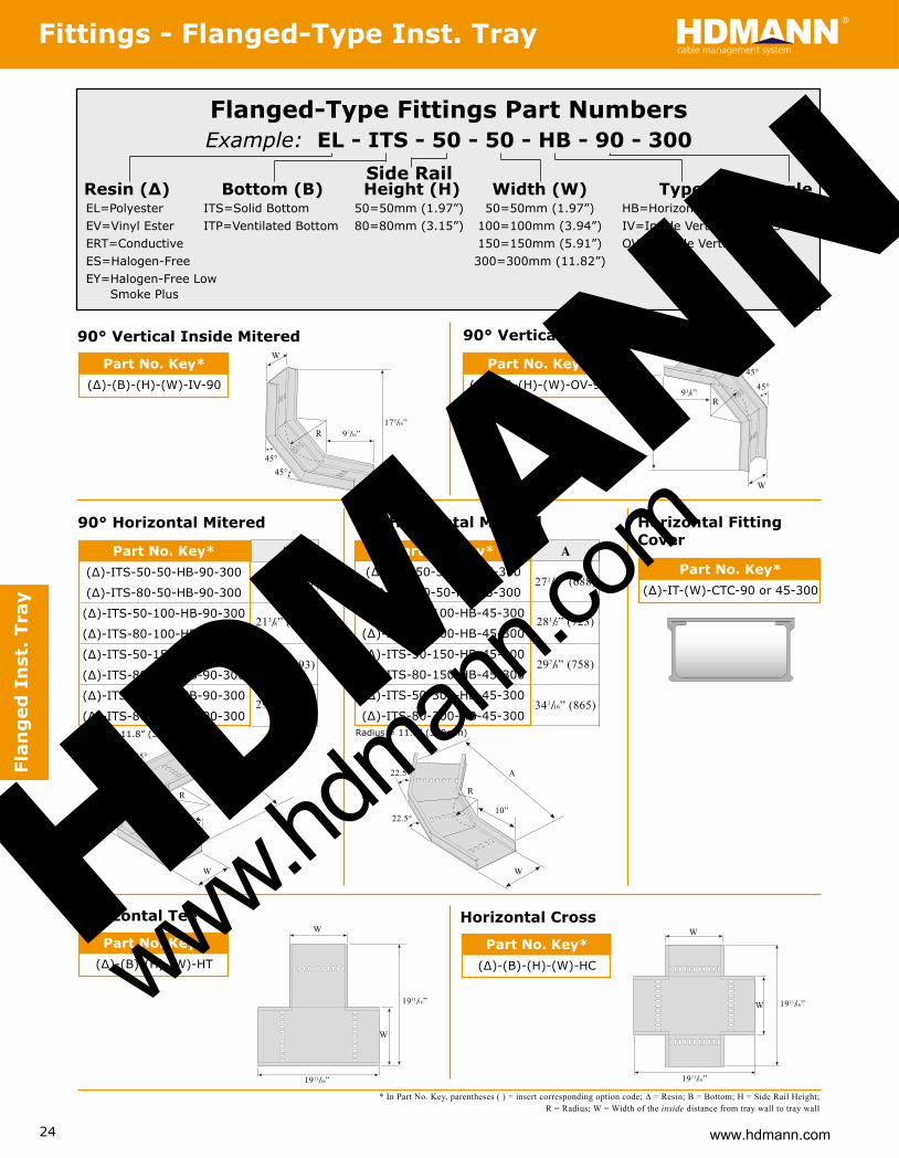
Flanged-Type Fittings Part NumbersExample: EL - ITS - 50 - 50 - HB - 90 - 300
Resin (∆) Bottom (B) Height (H) Width (W) Type Angle EL=Polyester ITS=Solid Bottom 50=50mm (1.97”) 50=50mm (1.97”) HB=Horizontal Bend 90=90° EV=Vinyl Ester ITP=Ventilated Bottom 80=80mm (3.15”) 100=100mm (3.94”) IV=Inside Vertical 45=45°
lacitreV edistuO=VO )”19.5( mm051=051 evitcudnoC=TRE )”28.11( mm003=003 eerF-negolaH=SE woL eerF-negolaH=YE
Smoke Plus
90° Horizontal Mitered
90° Vertical Inside Mitered 90° Vertical Outside Mitered
45° Horizontal Mitered
92 7/8” (758)
72 1/16” (688)
82 1/2” (723)
43 1/16” (865)
Part No. Key*(∆)-ITS-50-50-HB-45-300
(∆)-ITS-80-50-HB-45-300
(∆)-ITS-50-100-HB-45-300
(∆)-ITS-80-100-HB-45-300
(∆)-ITS-50-150-HB-45-300
(∆)-ITS-80-150-HB-45-300
(∆)-ITS-50-300-HB-45-300
(∆)-ITS-80-300-HB-45-300
A
Part No. Key*(∆)-(B)-(H)-(W)-IV-90
* In Part No. Key, parentheses ( ) = insert corresponding option code; ∆ = Resin; B = Bottom; H = Side Rail Height; R = Radius; W = Width of the inside distance from tray wall to tray wall
Flan
ged
In
st.
Tray
175/16”R 97/16”
45°45°
W
183/8”
R93/8”
45°
45°
W
A
R
101�4”45°
45°
W
A
R
10”22.5°
W
22.5°
Part No. Key*(∆)-(B)-(H)-(W)-OV-90
Side Rail
Part No. Key*(∆)-IT-(W)-CTC-90 or 45-300
Horizontal Tee
Part No. Key*(∆)-(B)-(H)-(W)-HT
Horizontal Cross
Part No. Key*(∆)-(B)-(H)-(W)-HC
Horizontal FittingCover
Radius = 11.8” (300mm) Radius = 11.8” (300mm)
W
1911/16”
W
1911/16”
W
1911/16”
W 1911/16”
HDMANN
www.hdman
n.com

25www.hdmann.com
Support Systems & Strutcable management systemHDMANN
Part No.Polyester: EC-10
Vinyl Ester: EC-VE-10
Lbs/Ft.
0.47
7/16”(11)
7/16”(11)
15/8”(41)
3/4”(19)
9/32”(7)
1”(25)
Part No.Polyester: EC-158
Vinyl Ester: EC-VE-158
.tF/sbL
0.68
15/8”(41)
9/32”(7)
3/4”(19)
7/16”(11)
7/16”(11)
15/8”(41)
Channel Framing (Solid & Punched)
For punched channel framing add “H” to the end of the part number; example: EC-10H. Punched not available for double channel. Punched holes are 9/16” holes on 2” centers. Replaces drilled strut.
For use in tray support systems, electrical conduit and tray rungs for tying down cable. Available in 10 ft and 20 ft lengths. See below for loading, and see page 38 for specif i cation information.
Su
pp
ort System
s
Part No.Polyester: EC-158D
Vinyl Ester: EC-VE-158D
.tF/sbL
1.36
3/4”(19)
7/16”(11)
7/16”(11)
9/32”(7)
15/8”(41)
15/8”(41)
31/4”(83)
9/16”(14)
9/16”(14)
1”(25)
2”(51)
* Deflection is in excess of 3.00 In. (76mm); mid-span support is recommended. NR = Not Recommended; Beam Loads: Table lists the total allowable load for various simple spans based on a minimum safety factor 2:1. If load is concentrated at center of span, multiply the load from the table by 0.5 and the corresponding deflection by 0.8. Column Loads: Table lists the total allowable axial load for various unsupported column heights based on a minimum safety factor of 3:1. Eccentric loads should be reduced according to standard practice. Notes: All beams should be supported in a manner to prevent rotation at supports. Long, deep beams should be tied between supports to prevent twist.
Channel Framing LoadingTechnical Data - Support Systems & Strut
Beam and Column Data: Polyester and Vinyl Ester Resin Base
In.(mm)
12”(305)
18”(457)
24”(610)
30”(762)
36”(914)
42”(1067)
48”(1219)
60”(1524)
72”(1829
84”(2134)
96”(2438)
Poly Vinyl Poly Vinyl Poly Vinyl Poly Vinyl .
EC-10 790 (358) 990 (449) 0.11 (3) 0.12 (3) - - - - 2550 (1156)EC-158 1720 (780) 2150 (975) 0.07 (2) 0.07 (2) - - - - 3650 (1655)EC-158D 5080 (2301) 6350 (2880) 0.04 (1) 0.04 (1) - - - - 7300 (3111)EC-10 530 (240) 670 (304) 0.24 (6) 0.27 (7) - 620 (281) - - 2350 (1066)EC-158 1150 (521) 1440 (653) 0.15 (4) 0.17 (4) - - - - 3370 (1528)EC-158D 5080 (2301) 4240 (1923) 0.09 (2) 0.10 (2) - - - - 6740 (3058)EC-10 400 (181) 500 (227) 0.43 (11) 0.48 (12) 240 (109) 270 (122) - - 2070 (939)EC-158 860 (390) 1080 (490) 0.27 (7) 0.30 (8) 810 (367) 910 (412) - - 2960 (1342)EC-158D 2540 (1152) 3180 (1442) 0.16 (4) 0.17 (4) - - - - 5920 (2685)EC-10 320 (145) 400 (181) 0.67 (17) 0.75 (19) 120 (54) 140 (63) 240 (109) 270 (122) 1710 (775) EC-158 690 (313) 870 (394) 0.42 (11) 0.48 (12) 410 (186) 460 (209) - - 2450 (1111)EC-158D 2040 (925) 2550 (1156) 0.24 (6) 0.27 (7) 2000 (907) 2350 (1066) - - 4900 (2222)EC-10 270 (122) 340 (154) 0.98 (25) 1.10 (28) 70 (31) 80 (36) 140 (63) 160 (72) 1260 (571)EC-158 580 (263) 730 (331) 0.61 (15) 0.69 (19) 240 (109) 270 (122) 480 (217) 540 (245) 1800 (816)EC-158D 1700 (771) 2130 (966) 0.35 (9) 0.39 (10) 1220 (553) 1370 (621) - - 3600 (1633)EC-10 230 (104) 290 (131) 1.32 (34) 1.49 (38) 50 (22) 55 (25) 100 (45) 115 (52) 920 (417)EC-158 490 (222) 620 (281) 0.82 (21) 0.92 (23) 150 (68) 170 (77) 300 (136) 340 (154) 1320 (598)EC-158D 1460 (662) 1830 (830) 0.48 (12) 0.62 (16) 770 (349) 870 (394) 1510 (650) 1720 (530) 2640 (1197)EC-10 200 (91) 250 (113) 1.72 (44) 1.92 (49) 30 (13) 25 (16) 60 (27) 70 (31) 700 (317)EC-158 430 (195) 540 (245) 1.07 (27) 1.20 (30) 100 (45) 115 (52) 200 (90) 230 (104) 1010 (458)EC-158D 1270 (576) 1590 (721) 0.62 (16) 0.69 (17) 520 (236) 590 (267) 1040 (471) 1170 (780) 2020 (916)EC-10 160 (72) 200 (91) 2.68 (68) 2.99 (76) 20 (9) 23 (10) 40 (18) 45 (20) 180 (81)EC-158 350 (158) 400 (200) 1.70 (43) 1.91 (48) 60 (27) 70 (32) 120 (54) 135 (61) 260 (118)EC-158D 1020 (462) 1280 (580) 0.97 (25) 1.09 (28) 270 (122) 310 (140) 540 (245) 610 (276) 520 (235)EC-10 140 (63) 180 (81) * * 10 (4) 12 (5) 20 (9) 23 (10) -EC-158 290 (131) 370 (168) 2.44 (62) 2.78 (71) 30 (13) 34 (15) 60 (27) 70 (32) -EC-158D 850 (385) 1070 (485) 1.40 (35) 1.57 (40) 160 (72) 180 (81) 320 (145) 360 (163) -EC-10 120 (54) 150 (68) * * NR - 12 (5) 15 (7) -EC-158 250 (113) 320 (145) * * 20 (9) 23 (10) 40 (18) 45 (20) -EC-158D 730 (331) 920 (417) 1.91 (48) 2.15 (55) 100 (45) 115 (52) 200 (90) 230 (104) -EC-10 100 (45) 130 (59) * * NR - - - - EC-158 220 (100) 250 (113) * * 13 (6) 15 (7) 26 (12) 30 (13) -EC-158D 640 (290) 800 (363) 2.50 (63) 2.79 (71) 70 (32) 80 (36) 140 (63) 160 (72) -
BeamSpan orColumnHeight
MaximumAllowableUniform
Beam Load
Deflection@ Maximum
AllowableUniform Beam Load
Uniform Load@ Maximum Deflection
= 0.25 In. (6mm)
Uniform Load@ Maximum Deflection
= 0.50 In. (13mm)
MaximumAllowable
Column Load
PartNo.
Lbs.(kg) Lbs.(kg) In.(mm) In.(mm) Lbs.(kg) Lbs.(kg) Lbs.(kg) Lbs.(kg) Lbs.(kg)
HDMANN
www.hdman
n.com

26
Connector Plates Based on individual applications, changes may be required on dimension and thickness of material. Please contact us. Holes are drilled to accept 3�8” and 1�2” bolts. For Vinyl Ester Connector Plates, insert the letters “VE” as indicated in this example: Polyester = CP-100; Vinyl Ester = CP-VE-100
Part No.Polyester: CP-501
Polyurethane: CP-PU-501
Nylon: CP-NY-501
Part No.CP-100
Part No.CP-101
Part No.CP-102
Part No.CP-103
Part No.CP-104
Part No.CP-105
Part No.CP-109
Part No.CP-110
Part No.CP-111
Part No.CP-112
Part No.CP-113
Part No.CP-114
Part No.CP-115
Part No.CP-116
Part No.CP-117
Part No.CP-118
Part No.CP-119
Part No.CP-120
Part No.CP-205
Part No.CP-209
Part No.CP-210
Part No.CP-211
Part No.CP-226
Part No.CP-405
Universal Angle
15�8”
51�4”
31�2”51�2”
31�4 ”15�8 ”
47�8”
15�8 ”15�8 ”
10”8”
45�8”
45�8”45�8”
6”
7”
7”
31�2”
31�2”
53�8”
31�2”
6”
45�8”
53�8”
53�8”
31�2”
31�2”
53�8”
31�2”
7”
7”
10”45�8” 10”
7”
7�8”
5”
Note: Flat washer not required for CP-205
7�8”
4”
15�8”
41�2”
7�8”
4”
15�8”
41�2”
15�8”
15�8”
21�4”
31�4”
7�8”
15�8”4”
41�2”
7�8”
4”
4”
Su
pp
ort
Sys
tem
s
www.hdmann.com
Support Systems & Strutcable management systemHDMANN
HDMANN
www.hdman
n.com

28
Hdmann’s Strut combined with our cable tray accessories are functional in many non-cable tray applications. Strut includes all the items necessary to f ield fabricate to your speci f ications whether wall, f loor, or ceiling mounted. Hdmann can also assist in engineering to your requirements.
If you need a special shape or assembly, call Enduro for information on custom pultrusions and fabrications.
Pipe Support Racks Sample Installation Wall Stanchion Sample Installation
Specifi cation
1.0 Scope1.1 This speci f i cation covers the requirements for Hdmann non-metallic Channel Framing Systems & Accessories
2.0 Standards2.1 All channel shall have a f iame spread rating of 25 or less, and the Smoke Developed Index shall have a density of 450 or less when tested in accordance with the provisions of ASTM E-84; therefore qualifying as a class 1 material in the Uniform Building Code2.2 All channel shall have a surfacing veil over the entire surface in addition to a UV inhibitor in the resin system to protect against degradation from ultra-violet light.
3.0 Materials3.1 All channel shall be manufactured by the pultrusion pro- cess, and contain a minimum of 50% glass by weight.3.2 All channel shall conform, as a minimum requirement, to loads and de f i ections shown on the tables in the lat- est version of the Enduro technical catalog.
4.0 Non-Metallic Pipe Clamps4.1 All pipe clamps shall be manufactured by the injection molding process with an impact modi f i ed, 30% glass f illed thermoplastic polyester resin.4.2 All pipe clamps interlock with the channel framing de- scribed above.4.3 All pipe clamps shall be designed for rigid PVC coated steel, Schedule 40 and 80 PVC, and f ilament wound
f iberglass pipe or conduit. Clamps shall be adjustable to accommodate a 3/4” minimum deviation in O.D. size.
5.0 Fasteners5.1 All fasteners shall be injected molded glass reinforced nylon, 316 stainless steel, or pultruded vinyl ester rod with ground threads and compression molded vinyl ester nuts.
Clevis Hanger
Pipe Clamps
Connector Plates
Channel Framing (EC158D)
Channel Framing (EC158)
Strut PostBase Multi-Tiered
Support Racks
Su
pp
ort
Sys
tem
s
www.hdmann.com
Typical Installations - Support Systems & Strutcable management systemHDMANN
HDMANN
www.hdman
n.com