
Cabinet Mount Arm (Pivoting) (Pull Out)
8
1 © 2011 Midmark Corp. | 60 Vista Drive Versailles, OH 45380 USA | 1-800-643-6275 | 1-937-526-3662 | 003-1256-00 Rev. S (11/3/16) Procenter Delivery Mounted on a Free Standing Treatment Console (FTC) Installation Components: none Special Tools: none Electrical Requirements: 24 VAC, 3.2 Amp 13VAC, 2 Amp DA2230i Note Locate three holes toward front of cabinet for proper rotation when installing. Note Leave push retainers on screws for install. Cabinet Mount Arm (Pivoting) Step 1: Align mounting holes in leveling plate and cabinet mount arm plate with mounting holes in cabinet. Secure with screws but do not tighten. Cabinet Mount Arm (Pull Out) Attention These instructions apply to Midmark cabinetry. For other cabinetry, additional steps may be required. Refer to 12:00 Procenter Delivery Mounting Kit Installation Instructions [002-10005-00] to confirm necessary steps have been com- pleted before proceeding with this installation.
Transcript of Cabinet Mount Arm (Pivoting) (Pull Out)
1© 2011 Midmark Corp. | 60 Vista Drive Versailles, OH 45380 USA | 1-800-643-6275 | 1-937-526-3662 |
003-1256-00 Rev. S (11/3/16)
Procenter Delivery Mounted on a Free Standing Treatment Console (FTC) Installation
Components:none
Special Tools:noneElectrical Requirements:
24 VAC, 3.2 Amp 13VAC, 2 Amp
DA2230i
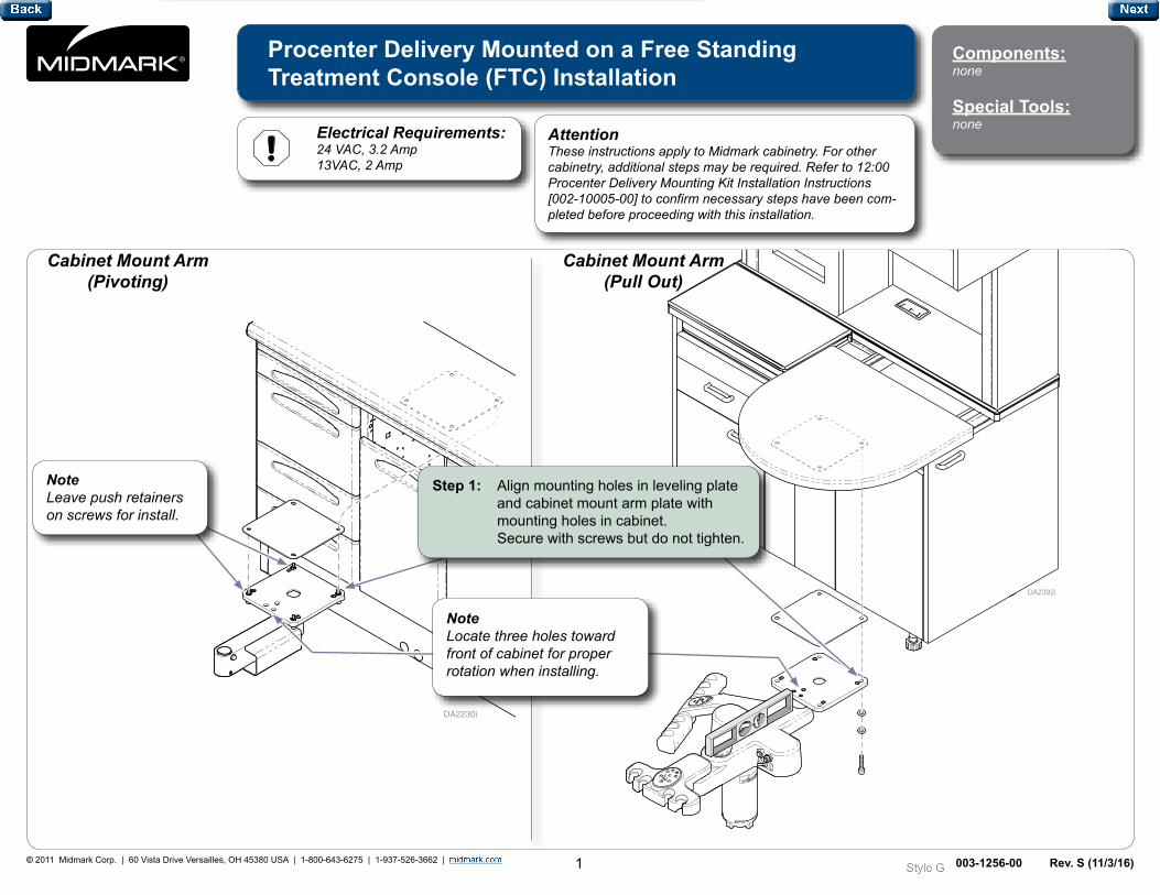
NoteLocate three holes toward front of cabinet for proper rotation when installing.
NoteLeave push retainers on screws for install.
Cabinet Mount Arm (Pivoting)
Step 1: Align mounting holes in leveling plate and cabinet mount arm plate with mounting holes in cabinet. Secure with screws but do not tighten.
Cabinet Mount Arm (Pull Out)
AttentionThese instructions apply to Midmark cabinetry. For other cabinetry, additional steps may be required. Refer to 12:00 Procenter Delivery Mounting Kit Installation Instructions [002-10005-00] to confirm necessary steps have been com-pleted before proceeding with this installation.
2© 2011 Midmark Corp. | 60 Vista Drive Versailles, OH 45380 USA | 1-800-643-6275 | 1-937-526-3662 |
DA2372i
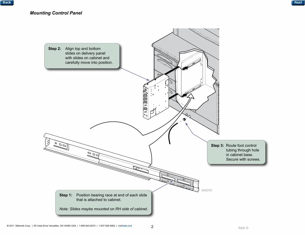
Mounting Control Panel
Step 2: Align top and bottom slides on delivery panel with slides on cabinet and carefully move into position.
Step 3: Route foot control tubing through hole in cabinet base. Secure with screws.
Step 1: Position bearing race at end of each slide that is attached to cabinet.
Note: Slides maybe mounted on RH side of cabinet.
3© 2011 Midmark Corp. | 60 Vista Drive Versailles, OH 45380 USA | 1-800-643-6275 | 1-937-526-3662 |
80 PSI
30 PSI
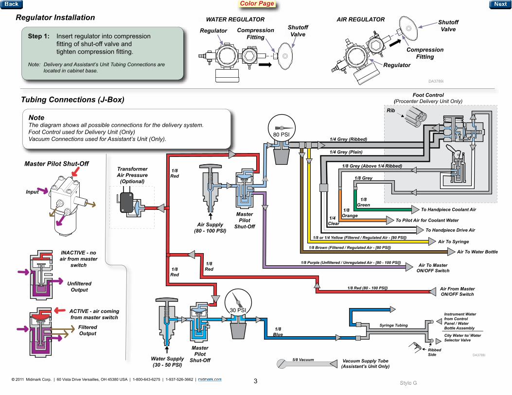
Regulator Installation
Step 1: Insert regulator into compression fitting of shut-off valve and tighten compression fitting.
Note: Delivery and Assistant’s Unit Tubing Connections are located in cabinet base.
NoteThe diagram shows all possible connections for the delivery system. Foot Control used for Delivery Unit (Only) Vacuum Connections used for Assistant’s Unit (Only).
TransformerAir Pressure
(Optional)
1/8Red
1/8Red
1/8Red
Air Supply (80 - 100 PSI)
Master Pilot
Shut-Off
Master Pilot
Shut-OffWater Supply (30 - 50 PSI)
Foot Control (Procenter Delivery Unit Only)
Rib
1/4 Grey (Ribbed)
1/4 Grey (Plain)
1/8 Grey (Above 1/4 Ribbed)
1/8 Grey
1/8 Green
1/8 Orange 1/4
Clear
To Handpiece Coolant Air
To Pilot Air for Coolant Water
To Handpiece Drive Air1/8 or 1/4 Yellow (Filtered / Regulated Air - [80 PSI])
Air To Syringe1/8 Brown (Filtered / Regulated Air - [80 PSI])
1/8 Purple (Unfiltered / Unregulated Air - [80 - 100 PSI])
1/8 Red (80 - 100 PSI])
Air To Water Bottle
Air To Master ON/OFF Switch
Air From Master ON/OFF Switch
Syringe Tubing
5/8 Vacuum
RibbedSide
Instrument Water from Control Panel / Water Bottle Assembly
City Water to/ Water Selector Valve
Vacuum Supply Tube (Assistant’s Unit Only)
Regulator Compression Fitting
Shutoff Valve
Shutoff Valve
Compression Fitting
Regulator
AIR REGULATOR WATER REGULATOR
Tubing Connections (J-Box)
1/8Blue
Master Pilot Shut-Off
Input
Unfiltered Output
Filtered Output
INACTIVE - no air from master
switch
ACTIVE - air coming from master switch
4© 2011 Midmark Corp. | 60 Vista Drive Versailles, OH 45380 USA | 1-800-643-6275 | 1-937-526-3662 |
DA2233-1i
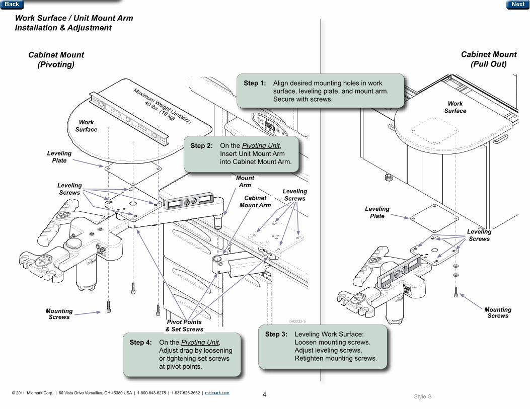
Step 2: On the Pivoting Unit, Insert Unit Mount Arm into Cabinet Mount Arm.
Mounting Screws
Leveling Screws
Work Surface
Leveling Plate
Mount Arm
Cabinet Mount Arm
Leveling Screws
Work Surface / Unit Mount Arm Installation & Adjustment
Cabinet Mount (Pull Out)
Cabinet Mount (Pivoting)
Step 1: Align desired mounting holes in work surface, leveling plate, and mount arm. Secure with screws.
Work Surface
Step 3: Leveling Work Surface: Loosen mounting screws. Adjust leveling screws. Retighten mounting screws.
Step 4: On the Pivoting Unit, Adjust drag by loosening or tightening set screws at pivot points.
Pivot Points & Set Screws
Mounting Screws
Leveling Screws
Leveling Plate
Maximum Weight Limitation
40 lbs. (18 kg)
5© 2011 Midmark Corp. | 60 Vista Drive Versailles, OH 45380 USA | 1-800-643-6275 | 1-937-526-3662 |
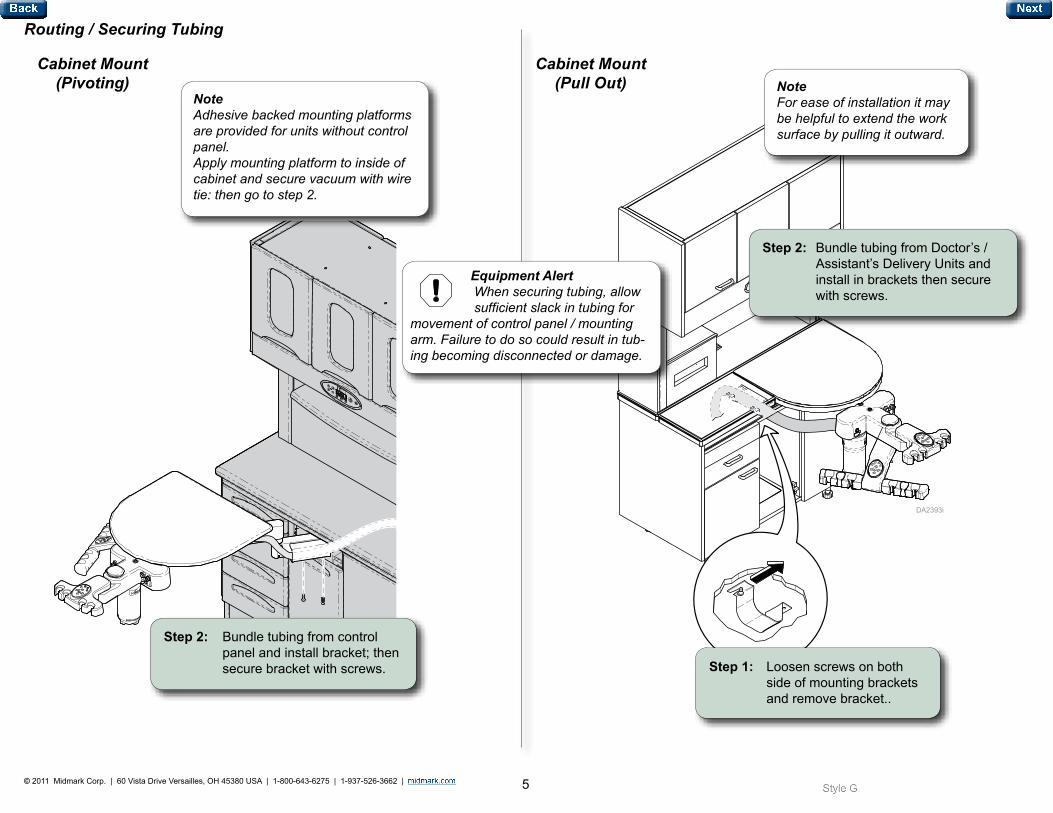
Routing / Securing Tubing
DA2394i
Equipment Alert When securing tubing, allow sufficient slack in tubing for movement of control panel / mounting arm. Failure to do so could result in tub-ing becoming disconnected or damage.
Step 2: Bundle tubing from control panel and install bracket; then secure bracket with screws.
Cabinet Mount (Pivoting)
NoteAdhesive backed mounting platforms are provided for units without control panel. Apply mounting platform to inside of cabinet and secure vacuum with wire tie: then go to step 2.
Cabinet Mount (Pull Out)
Step 1: Loosen screws on both side of mounting brackets and remove bracket..
Step 2: Bundle tubing from Doctor’s / Assistant’s Delivery Units and install in brackets then secure with screws.
NoteFor ease of installation it may be helpful to extend the work surface by pulling it outward.
6© 2011 Midmark Corp. | 60 Vista Drive Versailles, OH 45380 USA | 1-800-643-6275 | 1-937-526-3662 |
DA2395i
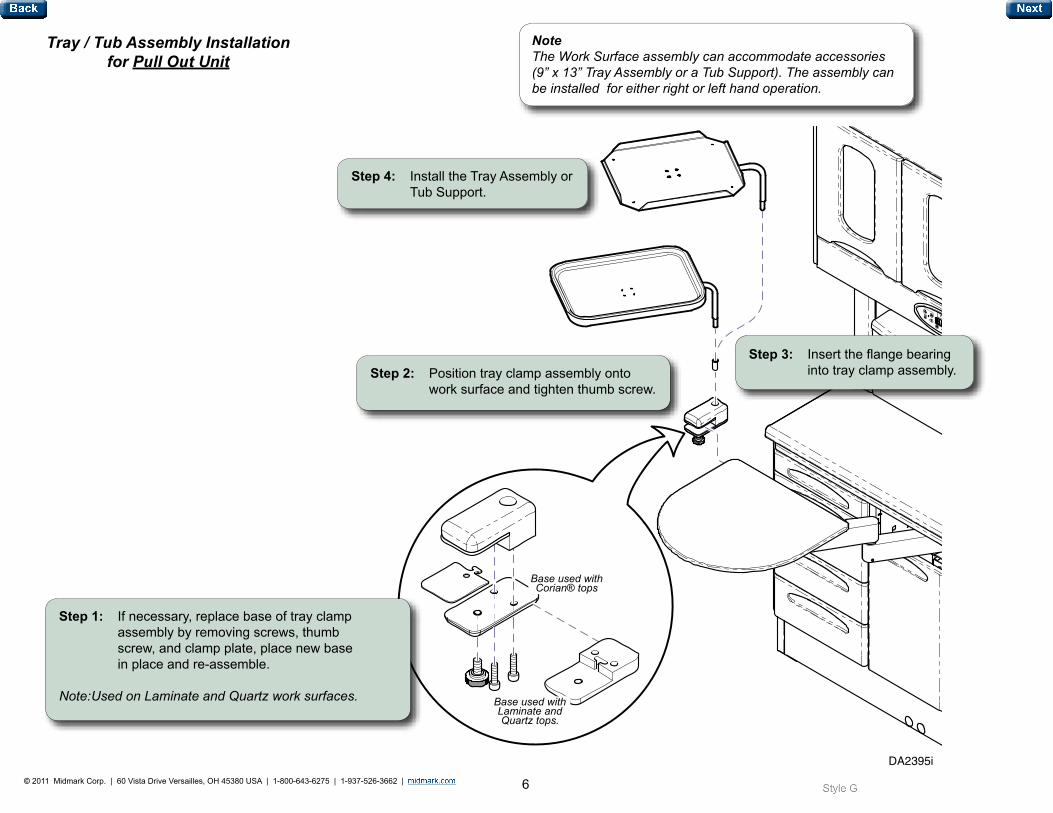
NoteThe Work Surface assembly can accommodate accessories (9” x 13” Tray Assembly or a Tub Support). The assembly can be installed for either right or left hand operation.
Step 4: Install the Tray Assembly or Tub Support.
Step 1: If necessary, replace base of tray clamp assembly by removing screws, thumb screw, and clamp plate, place new base in place and re-assemble.
Note: Used on Laminate and Quartz work surfaces.
Step 3: Insert the flange bearing into tray clamp assembly. Step 2: Position tray clamp assembly onto
work surface and tighten thumb screw.
Tray / Tub Assembly Installation for Pull Out Unit
Base used with Corian® tops
Base used with Laminate and Quartz tops.
7© 2011 Midmark Corp. | 60 Vista Drive Versailles, OH 45380 USA | 1-800-643-6275 | 1-937-526-3662 |
DA2371i
J13
J11
J10
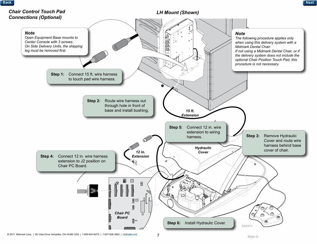
NoteThe following procedure applies only when using this delivery system with a Midmark Dental Chair. If not using a Midmark Dental Chair, or if the delivery system does not include the optional Chair Position Touch Pad, this procedure is not necessary.
Step 1: Connect 15 ft. wire harness to touch pad wire harness.
15 ft. Extension
NoteOpen Equipment Base mounts to Center Console with 3 screws. On Side Delivery Units, the shipping leg must be removed first.
Hydraulic Cover
Step 2: Route wire harness out through hole in front of base and install bushing.
12 in. Extension
Chair PC Board
J2
Step 3: Remove Hydraulic Cover and route wire harness behind base cover of chair.
Step 4: Connect 12 in. wire harness extension to J2 position on Chair PC Board.
Step 5: Connect 12 in. wire extension to wiring harness.
Step 6: Install Hydraulic Cover.
Chair Control Touch Pad Connections (Optional)
LH Mount (Shown)
8© 2011 Midmark Corp. | 60 Vista Drive Versailles, OH 45380 USA | 1-800-643-6275 | 1-937-526-3662 |
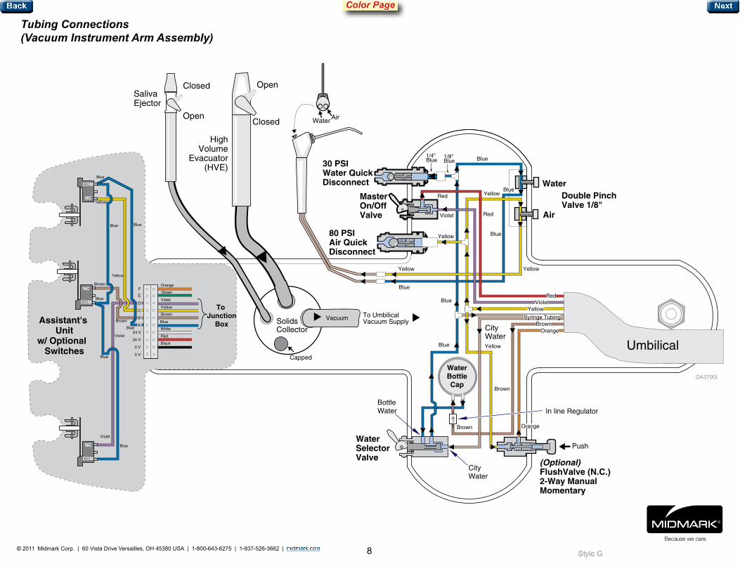
Tubing Connections (Vacuum Instrument Arm Assembly)
Water SelectorValve (Optional)
FlushValve (N.C.) 2-Way ManualMomentary
Double PinchValve 1/8"
Push
30 PSI Water QuickDisconnect
MasterOn/OffValve
80 PSIAir QuickDisconnect
N.C. LimitSwitch
N.C. LimitSwitch
N.C. LimitSwitch
CityWater
Syringe Tubing
WaterAir
Capped
To UmbilicalVacuum Supply
CityWater
BottleWater
Water
Air
Solids Collector
Vacuum
Open
Closed
HighVolume
Evacuator(HVE)
SalivaEjector
Open
Closed
Violet
Brown
Yellow
Blue
Blue
Blue
Blue
Blue
Violet
Black
Red
White
Blue
Brown
Yellow
Violet
Orange
Green
Blue
Blue
24 V
24 V
C
D
F
0 V
E
B
A
Brown
0 V
COM
NC
COM
NC
COM
NC
Yellow
To Junction
BoxAssistant's Unit
w/ Optional Switches
BrownOrange
YellowViolet
Red
Red
Violet
Blue1/4" Blue
1/8" Blue
Yellow
Yellow
Yellow
Red
Blue
Blue
Yellow
Blue
Blue
Blue
Brown
Yellow
Orange
Brown
WaterBottleCap
In line Regulator
Umbilical

![Direct Methods for Solving Linear Systems [0.125in]3 ...mamu/courses/231/Slides/CH06_2A.pdf · Motivation Partial Pivoting Scaled Partial Pivoting Outline 1 Why Pivoting May be Necessary](https://static.fdocuments.in/doc/165x107/5ab8ef507f8b9aa6018d3c00/direct-methods-for-solving-linear-systems-0125in3-mamucourses231slidesch062apdfmotivation.jpg)