CAB 8n Hardware Manual - peaveyoxford.com 8n Hardware Manual.pdf · CAB 8n Hardware Manual July 7,...
42
CAB 8n Hardware Manual Version 2.0.0.0 July 7, 2017
Transcript of CAB 8n Hardware Manual - peaveyoxford.com 8n Hardware Manual.pdf · CAB 8n Hardware Manual July 7,...

CAB 8n Hardware Manual
Version 2.0.0.0
July 7, 2017

ii Version 2.0.0.0 July 7, 2017
Copyright notice
The information contained in this manual is subject to change without notice. Peavey Electronics is not liable for
improper installation or configuration. The information contained herein is intended only as an aid to qualified
personnel in the design, installation and maintenance of engineered audio systems. The installing contractor or end
user is ultimately responsible for the successful implementation of these systems.
All creative content in this manual, including the layout, art design, content, photography, drawings, specifications
and all other intellectual property is Copyright © 2016 Peavey Electronics Corporation. All Rights Reserved. Features
& specifications subject to change without notice. All other registered trademarks or trademarks are the property of
their respective owners.
Email:[email protected] (mailto:[email protected]).
Scope
This guide describes how to physically install a CAB 8n and configure it with basic settings. It is assumed that you
have installed NWare and are familiar with how to use it effectively.
For information on NWare, refer to the NWare User Guide.

July 7, 2017 Version 2.0.0.0 iii
Contents
Chapter 1 Important safety instructions ................................................................ 1
Safety warnings ........................................................................................................................................ 2
Chapter 2 Before you start ..................................................................................... 5
Important network considerations ............................................................................................................ 6 Thank You! ............................................................................................................................................... 6 Warranty Registration ............................................................................................................................... 6 What's in the box? .................................................................................................................................... 6
Chapter 3 Introduction to the CAB 8n ................................................................... 7
Description ................................................................................................................................................ 8 Features.................................................................................................................................................... 8 Applications .............................................................................................................................................. 9 Front Panel .............................................................................................................................................10 Rear panel ..............................................................................................................................................11
Chapter 4 Installing the CAB 8n .......................................................................... 13
Introduction .............................................................................................................................................14 What you will need .................................................................................................................................16 Connections ............................................................................................................................................16 Setting the Hardware ID .........................................................................................................................24 Understanding gain structure .................................................................................................................25 What to do next ......................................................................................................................................25
Appendix A Reference Information .................................................................... 27
Serial communications ...........................................................................................................................28 GPIO overview .......................................................................................................................................29 Technical specifications ..........................................................................................................................30 Technical Support ...................................................................................................................................34
Warranty statement ................................................................................................. 37


July 7, 2017 Version 2.0.0.0 1
In This Chapter
Safety warnings ................................................................................................. 2
Chapte r 1
Important safety instructions

Chapter 1 - Important safety instructions
2 Version 2.0.0.0 July 7, 2017
.
Safety warnings
Warning: When using electrical products, basic cautions should always be followed,
including the following:
1. Read these instructions.
2. Keep these instructions.
3. Heed all warnings.
4. Follow all instructions.
5. Do not use this apparatus near water.
6. Clean only with a dry cloth.
7. Do not block any of the ventilation openings. Install in accordance with manufacturer’s
instructions.
8. Do not install near any heat sources such as radiators, heat registers, stoves or other
apparatus (including amplifiers) that produce heat.
9. Do not defeat the safety purpose of the polarized or grounding-type plug. A polarized plug
has two blades with one wider than the other. A grounding type plug has two blades and a
third grounding plug. The wide blade or third prong is provided for your safety. If the
provided plug does not fit into your outlet, consult an electrician for replacement of the
obsolete outlet.
10. Protect the power cord from being walked on or pinched, particularly at plugs,
convenience receptacles, and the point they exit from the apparatus.
11. Only use attachments/accessories provided by the manufacturer.
12. Use only with a cart, stand, tripod, bracket, or table specified by the manufacturer, or sold
with the apparatus. When a cart is used, use caution when moving the cart/apparatus
combination to avoid injury from tip-over.
13. Unplug this apparatus during lightning storms or when unused for long periods of time.
14. Refer all servicing to qualified service personnel. Servicing is required when the apparatus
has been damaged in any way, such as power-supply cord or plug is damaged, liquid has
been spilled or objects have fallen into the apparatus, the apparatus has been exposed to
rain or moisture, does not operate normally, or has been dropped.
15. Never break off the ground pin. Write for our free booklet Shock Hazard and Grounding.
Connect only to a power supply of the type marked on the unit adjacent to the power
supply cord.
16. If this product is to be mounted in an equipment rack, rear support should be provided.
17. Control panel devices, including the xControl range, D series and nTouch 60, are designed
for mounting in NEMA metal enclosures. Grounding to the front plate is required.
18. Note for UK only: If the colors of the wires in the mains lead of this unit do not
correspond with the terminals in your plug‚ proceed as follows:
a) The wire that is colored green and yellow must be connected to the terminal that is
marked by the letter E‚ the earth symbol‚
b) colored green or colored green and yellow.
c) The wire that is colored blue must be connected to the terminal that is marked with the
letter N or the color black.
CAB 8n Hardware Manual
July 7, 2017 Version 2.0.0.0 3
d) The wire that is colored brown must be connected to the terminal that is marked with
the letter L or the color red.
19. This electrical apparatus should not be exposed to dripping or splashing and care should be
taken not to place objects containing liquids, such as vases, upon the apparatus.
20. The on/off switch in this unit does not break both sides of the primary mains. Hazardous
energy can be present inside the chassis when the on/off switch is in the off position. The
mains plug or appliance coupler is used as the disconnect device, the disconnect device
shall remain readily operable.
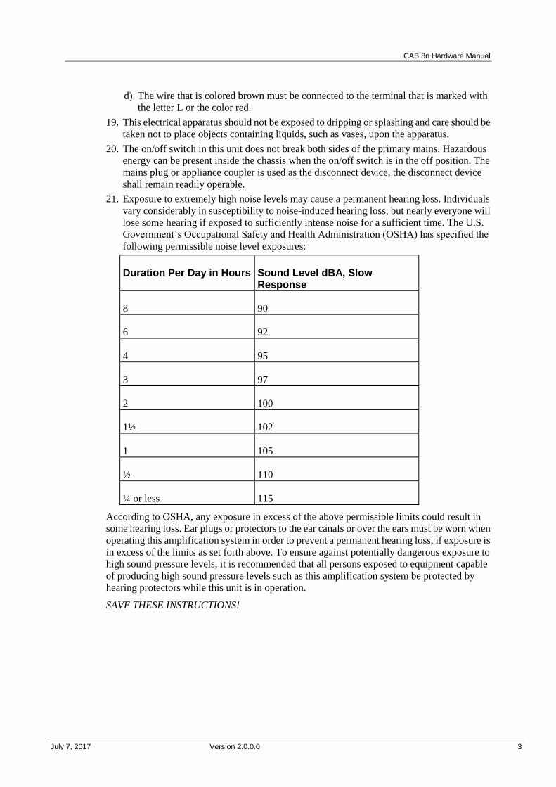
21. Exposure to extremely high noise levels may cause a permanent hearing loss. Individuals
vary considerably in susceptibility to noise-induced hearing loss, but nearly everyone will
lose some hearing if exposed to sufficiently intense noise for a sufficient time. The U.S.
Government’s Occupational Safety and Health Administration (OSHA) has specified the
following permissible noise level exposures:
Duration Per Day in Hours Sound Level dBA, Slow Response
8 90
6 92
4 95
3 97
2 100
1½ 102
1 105
½ 110
¼ or less 115
According to OSHA, any exposure in excess of the above permissible limits could result in
some hearing loss. Ear plugs or protectors to the ear canals or over the ears must be worn when
operating this amplification system in order to prevent a permanent hearing loss, if exposure is
in excess of the limits as set forth above. To ensure against potentially dangerous exposure to
high sound pressure levels, it is recommended that all persons exposed to equipment capable
of producing high sound pressure levels such as this amplification system be protected by
hearing protectors while this unit is in operation.
SAVE THESE INSTRUCTIONS!


July 7, 2017 Version 2.0.0.0 5
In This Chapter
Important network considerations ..................................................................... 6
Thank You! ....................................................................................................... 6
Warranty Registration ....................................................................................... 6
What's in the box? ............................................................................................. 6
Chapte r 2
Before you start

Chapter 2 - Before you start
6 Version 2.0.0.0 July 7, 2017
.
Important network considerations
This product is designed to operate on a network backbone or infrastructure. The
design, implementation and maintenance of this infrastructure is critical to correct
operation and performance of the product. Peavey Electronics Corp does not support
nor service network cabling, hubs, switches, patch bays, wall plates, connector
panels or any other type of network interconnect device. Please ensure that these
components and their associated installation techniques have been properly
designed and installed for audio and network applications.
Thank You!
Thank you for purchasing this MediaMatrix product. It is designed to provide years of
trouble-free operation and high quality performance. We are confident that you will find this
product and other MediaMatrix products to be of the highest quality.
Warranty Registration
Please take a few minutes and fill out the warranty registration card. Although your warranty is
valid without the registration, the information you provide with the form is crucial to our
support group. It enables us to provide better service and customer support, and to keep you
informed of new product updates.
Tip: Refer to the warranty statement at the rear of this manual for details of what your
warranty includes and what the limitations are.
What's in the box?
The CAB 8n is packaged in a single container. This container includes the following items:
CAB 8n
Power adapter with cable (120VAC Domestic, 230VAC Export)
Power supply cord with two-pin Mini Euro connector
User literature package.
If any of these items is missing, please contact your Authorized Peavey MediaMatrix
contractor/dealer.

July 7, 2017 Version 2.0.0.0 7
In This Chapter
Description ........................................................................................................ 8
Features ............................................................................................................. 8
Applications ...................................................................................................... 9
Front Panel ........................................................................................................ 10
Rear panel ......................................................................................................... 11
Chapte r 3
Introduction to the CAB 8n

Chapter 3 - Introduction to the CAB 8n
8 Version 2.0.0.0 July 7, 2017
.
Description
The CAB 8n Configurable Audio Bridge is an eight channel audio input and output device. It
is designed to be used with MediaMatrix NIONs in professional and commercial audio and
communications applications.
The cost-effective, 1U-high, half U-wide unit can be powered directly from the Ethernet
network using Power-over-Ethernet, or from a DC power supply. Each of the eight audio
channels can function either as an analog audio input to the CobraNet network, or as an analog
audio output.
Audio inputs accept microphone or line-level audio signals, and allow fine-grained remote
control of input gain. Up to 48V of phantom power is available per channel. Audio outputs
provide line-level audio signals with fine-grained remote level control, relay mute, and direct
signal monitoring.
The CAB 8n features a wide range of control interfaces, including eight channels of
configurable GPIO, each of which may be independently configured as logic input, logic
output, high-current voltage output or analog control voltage input. The unit also features two
dual-pole contact-closure circuits, a fault indicator contact-closure circuit, and an RS-232,
EIA-485 and EIA-422 full-duplex serial port.
Features
Eight channels of balanced analog audio,
independently selectable to be either
mic/line input with phantom power, or
line output
Remote control of input mic/line mode,
phantom power, input gain and output
level
Eight channels of GPIO independently
configurable as logic input, logic output,
analog control voltage input or
high-voltage output *
May be powered from
Power-over-Ethernet, or DC power
supply (included)
CobraNet audio networking interface
with 5.33ms latency, 48kHz sample rate
Two user-controllable contact closure
circuits, Fault contact closure circuit and
front-panel LED
Serial port that supports RS-232, EIA-485
and EIA-422 for interfacing with
third-party systems
High-current (1A) DC power output *
All audio interface control and
monitoring, audio metering, GPIO,
contact closure, serial port data and
hardware status remotely accessible via
the Ethernet network from within
MediaMatrix NWare software
Compact 1/2U-wide, 1U high chassis
Front panel LED audio level metering
Front-panel LED network activity and
power status indicators
Concealed front-panel rotary controls for
unit hardware ID selection
* High-voltage output GPIO mode and high-current power output not available when using
Power-over-Ethernet.

CAB 8n Hardware Manual
July 7, 2017 Version 2.0.0.0 9
.
Applications
Stadiums
Auditoriums
Arenas
Civic centers
Performing arts centers
Theaters
Courts of law
Houses of worship
Campus buildings
Theme parks
Hotel meeting rooms
Conference centers
Schools
Cruise ships
Teleconferencing
Distance learning
Large-scale paging
Multi-purpose facilities
Retail
Restaurants & bars
Gaming
Institutional paging
Communications
Correctional facilities
Professional complexes
Residential.

Chapter 3 - Introduction to the CAB 8n
10 Version 2.0.0.0 July 7, 2017
.
Front Panel
1. Status LEDs.
Link indicates that the physical layer connection has been established between the CAB
8n and the network switch. The status of the connection is also indicated by the Link LED
in the block in NWare.
Status/Data indicates that data is being transmitted or received from the CobraNet
network.
Power indicates that the CAB 8n is powered from an AC mains or PoE power source.
Fault indicates that a fault has occurred with the CAB 8n and the device has switched
to fault mode.
2. AUDIO METERS.
Peak reading LED ladder displays, indicating audio input/output levels. For inputs, the
signal level is displayed after the A/D converters. For outputs, the signal level is displayed
after the D/A converters.
3. REMOVABLE PANEL. Behind the panel are four rotary switches for setting the
hardware ID.

CAB 8n Hardware Manual
July 7, 2017 Version 2.0.0.0 11
.
Rear panel
1. AUDIO INPUT/OUTPUT CONNECTORS Eight channels of balanced analog audio,
independently selectable to be either mic/line input with phantom power, or line output.
These are identical to the NION audio connectors.
Note: If PoE is used, the total power consumed by the unit must not exceed 12.5W. If
more power is consumed, the unit will automatically shut down.
2. GPIO PORTS. Eight ports, independently configurable as digital out, high current digital
out, digital in or analog in at 10 bit resolution.
3. SERIAL PORT. Supports full duplex RS-232/EIA-485/EIA-422 serial communications
or half duplex EIA-485 serial communications. For information on the pin outs, see Serial
communications (on page 28).
4. CONTACT CLOSURES Ground pin (G), two user-controlled contact closure circuits
(R1 and R2), one fault indicator contact closure (RF) and one DC supply output connector.
The RF contact closure is activated when there is a fault with the CAB 8n and the Fault
LED on the front of the unit is lit.
Caution: If the Ext Pwr connector is used, the voltage available via the DC supply output
connector (marked DC Out) will be the same as the voltage supplied via the Ext Pwr
connector. Equipment connected to the DC Out connector must be compatible with the
supplied voltage.
Note: The DC Out connector cannot be used when the CAB 8n is powered using PoE.
5. FAULT CONNECTOR Three pin connector for linking the unit to a backup unit in a
fault tolerant configuration.
6. POWER CABLE RECEPTACLE Two-pin Mini Euro connector. Accepts 12-24V DC
at 1.6A.

Chapter 3 - Introduction to the CAB 8n
12 Version 2.0.0.0 July 7, 2017
Use only the supplied power supply with appropriate mains cable.
7. COBRANET NETWORK I/O Single RJ-45 connector provides interface to the
CobraNet audio network. This connector can also supply power to the unit if it is
connected to a Power over Ethernet (PoE) switch.

July 7, 2017 Version 2.0.0.0 13
In This Chapter
Introduction ....................................................................................................... 14
What you will need ........................................................................................... 16
Connections....................................................................................................... 16
Setting the Hardware ID ................................................................................... 24
Understanding gain structure ............................................................................ 25
What to do next ................................................................................................. 25
Chapte r 4
Installing the CAB 8n

Chapter 4 - Installing the CAB 8n
14 Version 2.0.0.0 July 7, 2017
.
Introduction
The CAB 8n is a 1RU device that can be mounted in a number of configurations:
In a 19" EIA equipment rack tray with one unit in the tray.
In a 19" EIA equipment rack tray with two units in the tray.
On a surface
Under a surface. The CAB 8n has four holes that pass right through the case (indicated by
the circles below), which are designed to allow it to be fixed under a surface by #8 or M4
screws.
This product should be installed so that its mounting position does not interfere with
proper ventilation. Do not block air intake or exhaust vents.

CAB 8n Hardware Manual
July 7, 2017 Version 2.0.0.0 15
The power switch in this unit does not break both sides of the primary mains.
Hazardous energy can be present inside the chassis when the power switch is in the
off position. The mains plug or appliance coupler is used as the disconnect device,
the disconnect device shall remain readily operable.

Chapter 4 - Installing the CAB 8n
16 Version 2.0.0.0 July 7, 2017
.
What you will need
A MediaMatrix NION with CobraNet interface.
The latest NWare software. (Updates can be downloaded from the MediaMatrix website
(http://www.peaveycommercialaudio.com/products.cfm/Software/NWare-Software/NWar
e-Software).)
A computer running Microsoft Windows, with monitor, mouse and keyboard.
An assortment of CAT 5e or CAT 6 cables.
At least 1 CAB 8n.
An audio source, cables, power amplifier and loudspeaker.
A small Phillips screwdriver.
A small flat-blade screwdriver.
A network switch connected to the CobraNet network.
Note: The selection of a proper network switch is critical for a successful implementation.
Although CobraNet is an Ethernet protocol, there are performance issues that must be
considered when selecting this switch for use in CobraNet audio systems.
In MediaMatrix, the minimum CAB 8n CobraNet system consists of a single NION, a CAB 8n
and a single Ethernet switch. Many systems will include more NIONs and CAB devices, but
this is the most basic configuration.
Connections
CobraNet network connection
The first priority is the CobraNet™ network connection. The RJ-45 connectors on the
CobraNet interface are designed to connect with standard, off-the-shelf Category 5, 5e or 6
cable for use with standard Ethernet network switches.
Notes:
The network must be properly designed for each system. If you lack experience in
networking, we suggest that you partner with someone with networking experience.
Gigabit switches are recommended.
CAT 5e or CAT6 cables are recommended.
A typical CobraNet system includes a connection from each CAB to a network switch. An
additional network cable connects the switch to one or more NION CM-1 cards.
Note: The example below is the most basic configuration. Large systems on managed
networks can get very complex. We recommend that you get this configuration working
before attempting a more complex one.

CAB 8n Hardware Manual
July 7, 2017 Version 2.0.0.0 17
Audio connections
Each audio connection on the CAB and NION products is a single, three-wire, balanced
analog circuit. The connections are identical for both microphone, line input and line output
connections. We recommend that audio connections are made with high quality shielded wire.
Notes:
As with any electronic connection, care should be taken to ensure that the termination is
solid. There should be no stray wire strands, kinks or nicks in the wire jacket for a proper
termination.
Stranded wires should not be soldered. Solder will cold flow under the pressure of the
screw terminal, causing a loose connection to develop over time.

Chapter 4 - Installing the CAB 8n
18 Version 2.0.0.0 July 7, 2017
If you want to connect an unbalanced audio source to the CAB or NION, make the connections
as shown in the table below.
Unbalanced input cable CAB or NION input connector
Positive (+) Positive (+)
GND GND and negative (-)
Serial connections
All CAB series products include a powerful feature that enables you to bridge serial data
between CAB locations on the audio network. You can think of this as a kind of sub-network
that travels across the audio network infrastructure independently of the audio data. This
feature has many uses, but is primarily for transporting control data.
Note: Ensure that your termination is correctly installed and high quality shielded wire is used.
Pin outs
The pin outs are detailed in the table below.
Pin RS-232 RS-485 RS-422
Tx+ N/C Data+ TxD+
Tx- TxD Data- TxD-
Rx+ RxD N/C RxD+
Rx- N/C N/C RxD-
SH GND GND GND

CAB 8n Hardware Manual
July 7, 2017 Version 2.0.0.0 19
CAT 5e and CAT 6 connections
Category 5e and category 6 cables (commonly known as CAT 5e and CAT 6) are two wiring
standards recommended for use with CobraNet networks.
Both cable types use a UTP (Unshielded Twisted Pair) configuration. CAT 5e cables typically
use 24–26 AWG wire. CAT 6 cable tends to have slightly more copper in each cable, with
standard gauges of 22–24 AWG. The cable is coupled to in-line RJ-45 connectors. As the
conductor sizes are generally the same, CAT 6 jacks may also be used with CAT 5e cable.
Special crimping tools are required to make the termination; these are widely available, as are
the connectors.
Note: A ratcheting type crimping tool is highly recommended. The use of non-ratcheting
crimping tools, while occasionally adequate, typically results in considerably higher failure
rates for field terminated connections.
There are stranded and solid varieties of CAT 5e and CAT 6 cable. The stranded form is more
flexible and withstands more bending without breaking and is suited for reliable connections
with insulation piercing connectors, but makes less reliable connections in
insulation-displacement connectors (IDCs). The solid form is less expensive and makes
reliable connections into insulation displacement connectors, but makes less reliable
connections in insulation piercing connectors.
When used for 10/100/1000BASE-T, the maximum allowed length of a CAT 5e or CAT 6
cable is 100 meters or 328 feet. This consists of 90 meters (300 ft) of solid horizontal cabling
between the patch panel and the wall jack, plus 10 meters (33 ft) of stranded patch cable
between each jack and the attached device. Since stranded cable has higher attenuation than
solid cable, exceeding 10 metres of patch cabling will reduce the permissible length of
horizontal cable.
Different types of connectors are used with either type of wire. There is a bent tine connector
intended for use with solid core wire, and an aligned tine connector for use with stranded
cable. The bent tine connector will generally work on stranded wire, but not the other way
around.
All cable types must be properly installed and terminated to meet specifications. The cable
must not be kinked or bent too tightly (the bend radius should be at least four times the outer
diameter of the cable). The wire pairs must not be untwisted and the outer jacket must not be
stripped back more than 1/2 inch (1.27 cm).
There are two main standards for termination: T568A and T568B. For more information on
the wiring for these standards, see Wikipedia
(http://en.wikipedia.org/wiki/T568A#T568A_and_T568B_termination).
Notes:
A single CAT 5e or CAT6 cable run must not exceed 100 meters.
Make sure your connector matches your cable type. If you are not sure, use the bent tine
variety.
When terminating CAT 5e or CAT6 cable, it is important that the natural twist of each pair
is carried through as close as possible to the point of termination at the connector.
We recommend that you familiarize yourself with the wiring color schemes so they are
second nature to you. An error in the cabling of an Ethernet network is often the primary
cause of system errors.

Chapter 4 - Installing the CAB 8n
20 Version 2.0.0.0 July 7, 2017
It is very important that you build the cable with all pairs properly terminated. This will
prevent any confusion later, and give your cable a solid mechanical connection.
The use of pre-made and pre-tested cabling can greatly simplify and expedite installation
for wiring within a rack.
There are two main standards for termination: T568A and T568B. It is important that both
ends of a cable are terminated in line with one of these standards and you do not use one
standard for one end of the cable and the other for the other end. The cable will not
function normally.

CAB 8n Hardware Manual
July 7, 2017 Version 2.0.0.0 21
.
Crossover cables
Normal network cables are designed to connect the CAB to a network switch only. You cannot
use this type of cable to connect a CAB directly to a NION CM-1 card. For that you need a
crossover cable.
A crossover cable is terminated the same way as a normal cable, except that the TX and RX
pins are swapped at one end to allow the transmit pair of one device to connect to the receive
pair of the other.
Operating modes and redundancy
The CAB 8n supports a number of different operating modes, which are selected using the
CAB 8n device in NWare. This section shows the physical connections that are required in
each case.
Normal operating mode
In this mode, the CAB 8n communicates with the NION on the CobraNet network and a
connection to the NION is required for the CAB to continue to operate.

Chapter 4 - Installing the CAB 8n
22 Version 2.0.0.0 July 7, 2017
Standalone mode
In this mode, once the CAB 8n has been configured using NWare and the project has been
deployed, the CAB 8n does not require a connection to a NION, nControl or nTouch 180 in
order to send and receive audio data on the CobraNet network. Even when the CAB 8n is
power cycled, it still continues to send and receive audio.

CAB 8n Hardware Manual
July 7, 2017 Version 2.0.0.0 23
Master/slave mode
In this scenario, two CAB 8ns are connected to the CobraNet network and also connected
together via the rear Fault IO connectors to provide a redundant system.
If a fault occurs on the master CAB, the slave will automatically take over and allow audio to
continue to flow through the system.
The amplifier is wired to both CABs, so that when a switchover is made from the active to the
standby unit, the interruption in audio output from the speakers is minimized.

Chapter 4 - Installing the CAB 8n
24 Version 2.0.0.0 July 7, 2017
The Fault connector on the rear of the CABs is wired up as follows: the Failout pin on the
master unit is connected to the failin pin of the slave. The Failout pin of the slave is not
connected.
Note: Do not connect the Failout pin of the slave to the master unit, as this will cause
oscillations between the two units.
Setting the Hardware ID
Once there is a physical connection to the network, you must assign a Hardware ID (also
referred to as a base address) to the CAB. This is an important step in the installation procedure
as the ID will be used to identify the unit on the network and allow audio to be passed through
it.
Tip: The Hardware ID is also specified in NWare to allow communications between the CAB
and its control panel (the yellow CAB 8n block ).
To set the Hardware ID
1. Remove the screws from the CAB face plate to gain access to the hardware ID switches.
Tip: If you look carefully, there is a small arrow on each switch indicating the selected
number.
2. Using a small Phillips screwdriver, carefully set each rotary switch to the desired number.
You will feel a click as you move between digits.
A Hardware ID has 4 digits. Acceptable values are in hex and range from 0001 to 7FFF.
From left to right, the four rotary switches represent your 4 digit Hardware ID.
Caution: Be careful not to damage a switch by using excessive force.

CAB 8n Hardware Manual
July 7, 2017 Version 2.0.0.0 25
Note: Each CAB on the network must have a unique Hardware ID.
Understanding gain structure
It is important to understand the basics of gain structure and how it relates specifically to the
CAB. In most cases, the CAB is shipped from the factory with unity gain through the unit. In
other words, if you introduce a 1.23VAC 1 kHz sine wave into the input channel of a CAB
without adjusting any controls, you will get the same 1.23VAC sine wave on an output
channel (when the signal paths are directly connected and without audio processing).
However, we recommend that unity gain settings are checked before testing the unit. The CAB
is primarily intended for larger MediaMatrix systems, where a different gain structure set up
may be required.
Adjusting the gain structure for the CAB is possible both at the analog and digital gain stages.
All controls for adjusting the input and output gain stages can be found on the control surface
of each CAB device in NWare. For more information, see Adjusting the gain structure in the
NWare User Guide.
What to do next
The CAB 8n is managed and configured using NWare. Refer to the section Adding a CAB 8n
to your design in the NWare User Guide to see how to use a CAB 8n in your audio system
design.


July 7, 2017 Version 2.0.0.0 27
In This Appendix
Serial communications ...................................................................................... 28
GPIO overview ................................................................................................. 29
Technical specifications .................................................................................... 30
Technical Support ............................................................................................. 34
Append ix A
Reference Information

Appendix A - Reference Information
28 Version 2.0.0.0 July 7, 2017
.
Serial communications
CAB 8n supports RS-232, RS-485 and RS-422 serial communications via a 5 pin connector on
the rear of the unit.
The pin outs are detailed in the table below.
Pin RS-232 RS-485 RS-422
Tx+ N/C Data+ TxD+
Tx- TxD Data- TxD-
Rx+ RxD N/C RxD+
Rx- N/C N/C RxD-
SH GND GND GND
Notes:
Only one protocol can be used at any one time.
The pin outs for each protocol are different.

CAB 8n Hardware Manual
July 7, 2017 Version 2.0.0.0 29
.
GPIO overview
NION and CAB products include a versatile GPIO (General Purpose Input Output) system at
the rear for terminating external logic, controls, relays and other external systems. Each
control pin is supported by NWare for configuration, control and monitoring. Any
combination of control pins may be used simultaneously, regardless of the configuration.
Caution: The pin assignments for the GPIO ports on the NION and CAB devices are not the
same. Please be sure to check the documentation carefully when connecting devices to the
ports.
Configurable general purpose ports (8 control pins)
These ports can be configured as follows:
Digital output 2.5V high level (LVTTL) short circuit current 1.4mA.
High current digital
output
Voltage is as supplied by external DC power (Ext Pwr connector).
Absolute max. current draw 0.5A per I/O. Total limited by external
PSU.
Not available if using PoE.
Digital input 2.5V high level (LVTTL) with reverse voltage and transient protection.
Analog input 10-bit resolution, 12V full-scale, reverse voltage and transient
protection.
Contact closure circuits
Two user-controllable contact-closure circuits. Max voltage 30V DC, max current 1A.
One fault indicator contact closure circuit. Max voltage 30V DC, max current 1A.
High current power output
Voltage is as supplied by external DC power (Ext Pwr connector). Absolute max. current draw
0.5A per I/O. Total limited by external PSU.
Not available if using PoE.
A ground pin is available on the left of the connector block if required.
Caution: If the Ext Pwr connector is used, the voltage available via the DC supply output
connector (marked DC Out) will be the same as the voltage supplied via the Ext Pwr
connector. Equipment connected to the DC Out connector must be compatible with the
supplied voltage.
Note: The DC Out connector cannot be used when the CAB 8n is powered using PoE.

Appendix A - Reference Information
30 Version 2.0.0.0 July 7, 2017
Technical specifications
Mechanical
Dimensions 8.5 in. (216 mm) W x 14.5 in. (368 mm) D x 1.57 in. (40 mm)
H
Weight 5.03 lbs. (2.28kg)
Mounting Mounting kit provided for installing either one or two CAB
8n units in a 1RU space.

CAB 8n Hardware Manual
July 7, 2017 Version 2.0.0.0 31
.
Mounting tray
Dimensions 17.28in. (439 mm) W x 14.23in. (361 mm) D x 1.72in. (44
mm) H
Designed to fit two CABs side-by-side or a single CAB with
a blanking plate.

Appendix A - Reference Information
32 Version 2.0.0.0 July 7, 2017
.
Performance
ADC/DAC 48kHz sample rate; 24 bit resolution.
Frequency Response +0/-0.3 at unity gain.
THD <= 0.01% mic, <= .006% line in or out.
Input noise <= -126 dBu.
Input sensitivity -48dBu to +24dBu
Input gain 0 to -96dB analog gain control
Dynamic range (for inputs) >= 110 dB
Output sensitivity 0dBu to 24dBu, 6dB step
Output gain Analog gain control
Common Mode Rejection
Ratio (CMRR)
(for inputs) >= 70 dB
Crosstalk < = 95 dB
Input level Up to 24 dBu
Output level Up to 18 dBu
Input impedance 10k to 22k ohms is acceptable
Output impedance 100 ohms
Mic phantom 48V software selectable on or off. Phantom power is
automatically disabled if I/O is configured as an output.

CAB 8n Hardware Manual
July 7, 2017 Version 2.0.0.0 33
.
General
A/D, D/A Quantization 16, 20 or 24 bit. Default is 20 bit.
Audio Transmission
Quantization
On CobraNet: 16, 20 or 24-bit. Default is 20 bit.
Sample Rate (Fs) 48 kHz
Master Clock Speed (256 Fs) 24.576 MHz
Digital Audio Channels per
unit
8 channels on CobraNet
Digital Audio Interface CobraNet I/O: 100 BaseT Ethernet, Uses standard
8-conductor RJ-45 jack
Serial port RS-232/EIA-485/EIA-422 port. One serial port
capable of full duplex RS-232/EIA-485/EIA-422
serial communications or half duplex EIA-485
serial communications.
Fault/Failover ports
1 input, 1 output Phoenix connectors
Power consumption PoE: max. 12.5W
External DC supply: 20W (excluding high current
outputs)
DC voltage 12V
DC line current 1.6A
Power Dissipation To be confirmed.
Finish Black powder coat, painted steel

Appendix A - Reference Information
34 Version 2.0.0.0 July 7, 2017
.
Front panel LEDs
Meter LED displays (numbered 1-4 and 5-8)
Meaning
Top line flashing The unit is in boot loader mode but has no programme code to
run.
All LEDs flashing on and
off
The unit is in boot loader mode and has programme code which
it can run.
LEDs changing in time to
audio
Normal display mode for the unit. Each numbered column of
LEDs represents the dB level of the corresponding channel.
LED column moving left to
right
No NION is controlling this CAB.
LED row moving bottom to
top
The unit is in test mode. This display is shown when the CAB is
starting up.
Arrows moving left to right
across LED bar
The unit is in standby mode. It has been connected to another
CAB via the Fault connector at the rear of the unit.
When a unit is a slave in a master/slave configuration, this
display is shown continuously. If a master unit fails, but is then
subsequently available, this display will be shown momentarily
before the master assumes control from the slave unit.
No LEDs lit The unit is powered and connected to the CobraNet network, it
has been assigned a hardware ID from NWare and is now being
controlled by a NION. No audio is passing through the unit.
Technical Support
When you require assistance with your product, you can get help from several sources. Apart
from the online Knowledge Center, there are many technical documents, white papers and
application notes on our website and on other websites on the Internet, covering subjects
including Python programming, SNMP and serial control.
If you cannot find the information you require, contact your dealer or distributor. If you are
still unable to solve the issue, you can contact us directly using the details below. MediaMatrix
has an extensive Technical Services Group that provides technical support, repair and
implementation services.
Peavey Electronics Corp.,
MediaMatrix Division,
5022 Hartley Peavey Drive,
Meridian, MS 39305, USA.

CAB 8n Hardware Manual
July 7, 2017 Version 2.0.0.0 35
Phone: 601.483.9548
Phone (toll free): 866.662.8750
Fax: 601.486.1678
Website: http://mm.peavey.com (http://www.peaveycommercialaudio.com/).


July 7, 2017 Version 2.0.0.0 37
MediaMatrix® PEAVEY ELECTRONICS CORPORATION DOMESTIC (USA) LIMITED WARRANTY Effective Date: May 1, 2005
What This Warranty Covers
This Warranty covers defects in material and workmanship in
Peavey MediaMatrix products purchased and serviced in the United
States of America (USA).
What This Warranty Does Not Cover
The Warranty does not cover: (1) damage caused by accident,
misuse, abuse, improper installation or operation, rental, product modification or neglect; (2) damage occurring during shipment; (3)
damage caused by repair or service performed by persons not
authorized by Peavey; (4) products on which the serial number has been altered, defaced or removed; (5) products not purchased from
an Authorized MediaMatrix Integrator. This warranty does not
cover associated costs incurred from servicing equipment, including, but not limited to, travel, jobsite-related costs,
fabrication, freight, loaner equipment, installation, cabling or
harnessing, mounting materials or other variable costs.
Who This Warranty Protects
In applications where the product is sold over the counter, this
Warranty protects the original retail purchaser. In applications
where the product is part of an integrated system, and such system is warrantied by the integrator as a complete assembly, this Warranty
protects only the system integrator.
What Peavey Will Do
We will repair or replace (at Peavey's discretion) products covered
by warranty at no charge for labor or materials. If the product or
component must be shipped to Peavey for warranty service, the
consumer must pay initial shipping costs. If the repairs are covered by warranty, Peavey will pay the return shipping costs.
How Long This Warranty Lasts
The Warranty begins on the date of purchase by the original retail
purchaser or on the date received by the system integrator. (See Who This Warranty Protects, above). The duration of the Warranty
varies by product as summarized below.
5 Years MediaMatrix® DPU cards, NION™ Processing
Nodes, CABs, I/O cards, Cinema Processors, Power Amplifiers, Pre-Amplifiers, Mixers, Electronic Filter
Sets and Dynamics Processors.
1 Year MM Series Cardframes, MF Series Cardframes,
ControlMatrix™ Host Processors, Servers and
Controllers, nControl, nTouch 180, nTouch 60, xControl LCDs, nWall, VCAT, VCAT-HD, VGA-2,
VSC, D4S, D1V, Remote Control Panels, Plates,
Paging Stations, Ambient Sense Devices and other devices installed in user-accessible locations.
90 Days Loudspeaker Components (including speakers,
baskets, drivers, diaphragm replacement kits and
passive filter networks.) and all Accessory Products
How To Get Warranty Service
End Users: Take the defective product and your dated sales receipt
or other proof of purchase to your Authorized MediaMatrix Systems
Integrator or Authorized Peavey Service Center. System Integrators: Ship the defective product, prepaid, to Peavey
Electronics Corporation, International Service Center, 412 Highway
11 & 80 East, Meridian, MS 39301, 601-483-5365. Include a detailed description of the problem, the name and location of the
jobsite and a copy of your invoice as evidence of warranty coverage. Please include a complete return shipping address.
Limitation of Implied Warranties
ANY IMPLIED WARRANTIES, INCLUDING WARRANTIES
OF MERCHANTABILITY AND FITNESS FOR A PARTICULAR PURPOSE, ARE LIMITED IN DURATION TO
THE LENGTH OF THIS WARRANTY.
Some states do not allow limitations on how long an implied
warranty lasts, so the above limitation may not apply to you.
Exclusions of Damages
PEAVEY'S LIABILITY FOR ANY DEFECTIVE PRODUCT IS
LIMITED TO THE REPAIR OR REPLACEMENT OF THE
PRODUCT, AT PEAVEY'S OPTION. IF WE ELECT TO REPLACE THE PRODUCT, THE REPLACEMENT MAY BE A
RECONDITIONED UNIT. PEAVEY SHALL NOT BE LIABLE
FOR DAMAGES BASED ON INCONVENIENCE, LOSS OF USE, LOST PROFITS, LOST SAVINGS, DAMAGE TO ANY
OTHER EQUIPMENT OR OTHER ITEMS AT THE SITE OF
USE, OR ANY OTHER DAMAGES WHETHER INCIDENTAL, CONSEQUENTIAL OR OTHERWISE, EVEN IF PEAVEY HAS
BEEN ADVISED OF THE POSSIBILITY OF SUCH DAMAGES.
Some states do not allow the exclusion or limitation of incidental or
consequential damages, so the above limitation or exclusion may not apply to you. This Warranty gives you specific legal rights, and
you may also have other rights which vary from state to state. If you
have any questions about this warranty or service received, or if you need assistance in locating an Authorized Service Center, please
contact the Peavey International Service Center at (601) 483-5365.
Features and specifications subject to change without notice.
Warranty statement

MediaMatrix® A Division of Peavey Electronics Corp.
5022 Hartley Peavey Drive, Meridian Mississippi, 39305, USA
Phone: 866.662.8750
http://www.peaveycommercialaudio.com/products.cfm/mm/
Features & Specifications subject to change without notice
Copyright © 2016, All Rights Reserved
80307506