CA F/6 13/9 UNCLASSIFIED 1i//II/m/lE REMOTE UNMANNED R … · d i jan 73 1473 edition of i nov osis...
41
AAG 859 NAVAL OCEAN SYSTEMS CENTER SAN DIEGO CA F/6 13/9 REMOTE UNMANNED WORK SYSTEM PRIMARY CABLE TERMINATION AND POTTI-ETC(U) ,1UN 80 R S STARK UNCLASSIFIED NOSC/TD-350 1i//II/m/lE inunnnuu
Transcript of CA F/6 13/9 UNCLASSIFIED 1i//II/m/lE REMOTE UNMANNED R … · d i jan 73 1473 edition of i nov osis...

AAG 859 NAVAL OCEAN SYSTEMS CENTER SAN DIEGO CA F/6 13/9
REMOTE UNMANNED WORK SYSTEM PRIMARY CABLE TERMINATION AND POTTI-ETC(U),1UN 80 R S STARK
UNCLASSIFIED NOSC/TD-3501i//II/m/lEinunnnuu

LEVEL
0 ~
Technical Document 350---
/ REMOTE UNMANNED WORK.SYSTEM \,! PRIMARY CABLE TERMINATION AND ',
POTTING PROCEDURES,
Robert S. ta ;
,. .Prepared for'ava Sea Systems Command
DTICj d" '- g, ,/ eELECTE
JUL 2 11980
. , B
Approved for public release; distribution unlimited B
NAVAL OCEAN SYSTEMS CENTERSAN DIEGO, CALIFORNIA 92152
80 7 18 01

NAVAL OCEAN SYSTEMS CENTER, SAN DIEGO, CA 92152
AN ACTIVITY OF THE NAVAL MATERIAL COMMAND
SL GUILLE, CAPT, USN HL BLOODCommander Technical Director
ADMINISTRATIVE INFORMATION
This document presents information concerning the methods and materialsconsidered most effective in field termination and potting of the primary cable for the
Remote Unmanned Work System (RUWS). It is intended to assist those individuals who will
be working with the cable at sea and in the field.
This work was performed at the Naval Ocean Systems Center Hawaii Laboratory as
a part of the Deep Ocean Technology (DOT) program.
Released by Under authority of
JK KATAYAMA, Head JD HIGHTOWER, HeadOcean Systems Division Environmental Sciences Department

UNCLASSIFIED;ECUiPITY CLASSIFICATION OF THIS PAGE (When Date Entered)" READ INSTRUCTIONS
REPORT DOCUMENTATION PAGE RE COMPRETIORMBEFORE COMPL.ETING FORM
A 1. REPORT NUMBER 2. GOVT ACCESSION NO. 3. RECIPIENT'S CATALOG NUMBER
NOSC TD 3 50- o
4. TITLE (and Subtitle) S. TYPE OF REPORT & PERIOD COVERED
REMOTE UNMANNED WORK SYSTEM PRIMARY CABLE Final: 1978-1980
TERMINATION AND POTTING PROCEDURES 6. PERFORMING ORG. REPORT NUMBER
7. AUTHOR(s) 8. CONTRACT OR GRANT NUMBER(@)
R.S. STARK
S. PERFORMING ORGANIZATION NAME AND ADDRESS 10. PROGRAM ELEMENT, PROJECT. TASK
Naval Ocean Systems Center, Hawaii Laboratory AREA I WORK UNIT NUMBERS
P. 0. Box 997 63712N; S0397-SL 14669;Kailua, Hawaii 96734 533-MS67
II. CONTROLLING OFFICE NAME AND ADDRESS tZ. REPORT DATE
Naval Sea Systems Command June 1980Department of the Navy 13. NUMBER OF PAGES
Washington, D. C. 20360 3614. MONITORING AGENCY NAME & ADDRESS(If different from Controillng Office) 15. SECURITY CLASS. (of this report)
Unclassified
ISa. DECLASSIFICATION/DOWNGRADINGSCHEDULE
16. DISTRIBUTiON STATEMENT (of this Report)
Approved for public release; distribution unlimited.
17. DISTRIBUTION STATEMENT (of the abstree entered In Block 20, if different from Report)
IS. SUPPLEMENTARY NOTES
19. KEY WORDS (Continue on reverse aide if neceeery end Identify by block number)
Electromechanical cablePotting compoundsPotting proceduresTermination
20. AIIS? ACT (Continue an reveree stde it neesesery end identify by biock nmbsr)
This procedure for potting and terminating the strength and electrical portions of the primary cable ofthe Remote Unmanned Work System (RUWS) are discussed. Also included are lists of tools and materials to beused in the process.
D I JAN 73 1473 EDITION OF I NOV OSIS OSOLETE UNCLASSIFIEDS/N 0102-LF.014-6601
SECURITY CLASIIrCATION OF THIS PACE (Wfhen DOfI 60140'")

UCT ARRIFIEI)SIECU44ITY CLASSIFICATION OF THIS PAGE (UVma Data Me~tr*4
UNCLASSIFIEDSECURITY CLASSIFICATION Of THIS PAGErwpeaf Date Entecd)

CONTENTS
INTRODUCTION... page 3
DESCRIPTIONS... 3
REMOTE UNMANNED WORK SYSTEM... 3
PRIMARY CABLE... 3
Center Conductor... 3Dielectric ... 5Shield Conductor... 5Shield Tapes ... 5Electrical Jacket ... 5Loadbearing Strength Members ... 5Polyester Isolation Tape ... 5Subsurface Terminations ... 5
PROCEDURES... 6
STRENGTH TERMINATION... 6
Preparation ... 6Potting Fixture Assembly ... 11
ELECTRICAL CONNECTOR TERMINATION... 21
Preparation... 21Assembly and Potting of the Connector... 23
APPENDICES
A. Termination Parts... 27B. List of Materials... 28C. List of Fixtures and Tools... 29D. Solvents and their Uses.. . 30E. Urethane Metal Primer Mixing Instructions ... 31F. Use of Nonmetallic Primer... 32 ACCESSION forG. Epoxy Mixing, Degassing and Cure Cycle... 33 NTIS White S'etionH. Urethane Mixing, Degassing and Cure Cycle... 34 DOC Buf SeCtIon (3
UNANNOUNCED aJUSTIFICATION
By
DisUTAV NLAWIIW?Dist. AVAIL and/or PECKL

ILLUSTRATIONS
1. The Remote Unmanned Work System concept... 4
2. Cross section of the RUWS primary cable... 4
3. Strength termination cone... 7
4. Masking and sandblasting the strength termination cone... 7
5. Termination stand and scaffold ... 8
6. Termination stand construction... 9
7. Checking the cable lay length ... 10
8. Wrapping and clamping the cable end... 10
9. Assembling the termination fixture ... 11
10. Cable threaded through scaffold and stand ... 12
11. Assembling the termination fixture ... 13
12. Suspending the vacuum chamber... 14
13. Kevlar layers unwrapped ... 15
14. Stringing the elements to the separator ring ... 16
15. Affixing the electrical lugs ... 17
16. Termination fixture assembled... 18
17. Assembling the mold... 20
18. Cutting the cable end ... 21
19. Cleaning and tinting the shield ... 22
20. Exploded view of the connector... 23
21. Assembled cable and connector housing... 25
22. Cable and connector assembly in vacuum chamber ... 25
23. Preparing connector strain relief... 26
24. The final connector ... 26

INTRODUCTION
This document describes the procedures for potting and terminating the strengthand electrical portions of the primary cable of the Remote Unmanned Work System (RUWS).Also included are lists of tools and materials to be used in the process.
DESCRIPTIONS
REMOTE UNMANNED WORK SYSTEM
The RUWS is a major element of the Navy's Deep Ocean Technology project. Anunmanned, cable-tethered work system, RUWS is designed to perform a variety of engineer-ing and scientific tasks at ocean depths to 6,100 metrcs (20,000 feet). It was designed for airtransport and operation from specified ships of opportunity. The system includes advancedcapabilities for high-accuracy, deep-ocean navigation and local-area bottom search. Figure Idepicts the RUWS concept.
PRIMARY CABLE
The primary cable of the RUWS (figure 2) is an electromechanical cable whichtethers the submersibles to their control van on the support ship. It consists of a centralcoaxial electrical cable surrounded by two layers of a contrahelically-wound strength mem-ber. The strength member is constructed of Kevlar-49 organic fiber in a matrix of ether-basedpolyurethane.
Kevlar49, formerly known as PRD-49, is a recent development of duPont. This newsynthetic, high strength/weight material is used as the strength member for the primary ca-ble. The basic fiber is supplied in a multiple filament yarn and is twisted in a polyurethanematrix into strength members which correspond to the individual steel wires in a conven-tional electromechanical cable.
These new strength members have shown outstanding resistance to flexure fatigue.load cycling and pressurization. Samples have been submitted to over 2,000,000 flexurecycles (20 percent loading) without degradation of tensile strength. Other samples have beensoaked and cycled to 10,000 psi (703 kg/cml , ) in salt water without loss of strength, andwith no measurable water absorption. The material showed little or no degradation during12 months of ocean exposure.
Center Conductor
The center conductor of the cable consists of 36 wires, each 0.032 inch in diameter.wrapped in left/right/left helices around a 0.032-inch-diameter thermoplastic core. A com-mon lay angle of 17 degrees is used for all helices. The wires are copper, but those in theouter helix are coated with silver to reduce high-frequency resistance. All closed voids arefilled with polyethylene grease. The conductor OD is 0.224 inch.
3

I
MOTION - COMPENSATED WINCH -
PRIMARY CABLE
PCT - -- / TETHER CABLE
VEHICLE
OCEAN BOTTOM" '---" "-"
Figure 1. The Remote Unmanned Work System Concept.
44 TENSION MEMBERS.0730 DIA.
28 TENSION MEMBMSE.097 DIA.
POLYETHYLENE JACKET
POLYETHYL.ENE
DIELECTRIC 1.200a DIA.
CENTER CONDUCTOR
60 SPIRALLY SERVED COAXIALCONDUCTOR WIRES OVERWRAPPEDWITH COPPER COATED POLYESTERTAPE
Figure 2. Cross section of the RUWS primary cable.

Dielectric
Low density natural polyethylene is extruded to a diameter of 0.780 inch; thenshaved to a final circular diameter of 0.700 inch.
Shield Conductor
Sixty 0.032-inch, silver-coated copper wires are applied as a 31.5-degree, left-handhelix, and voids are filled with polyethylene grease. Design OD is 0.743 inch.
Shield Tapes
To prevent EMI, RFI and crosstalk, a copper-on-polyester tape is wrapped, copperside down, around the shield wires. The wrap consists of 0.0007-inch-thick copper on0.00092-inch polyester laid directly over the shield wires with a SO-percent overlap and aright-hand lay. An adhesive polyester tape is then applied, left hand, also with a 50-percentoverlap.
Electrical Jacket
This is a high-density, black polyethylene applied to provide a final diameter of0.869 inch.
Loadbearing Strength Members
This is a contrahelix of 72 tension members. Each tension member is constructed asa 1.0-inch-lay, bunched helix of Kevlar-49 filaments in a void-free urethane matrix. The innercable helix consists of 28 members, each 0.097 inch in diameter, in a 20.6-degree, right-handlay. The outer helix has 44 members, each 0.073 inch in diameter, in a 14-degree left-handlay. The design final diameter of the cable is 1.213 inches before any preconditioning opera-tions.
Polyester Isolation Tape
Two 1-mil tapes are applied as a contrahelix spacer between the two Kevlar-49helices. Each tape is laid with a gap of approximately 0.05 inch between adjacent wraps.This results in a series of diamond-shaped holes which allow seawater to propagate freelyamong the Kevlar tension members.
Subsurface Terminations
At the Primary Cable Termination (PCT) end of the primary cable, the cable strengthmembers are potted in a stainless steel termination housing. This housing is clamped to thePCT strongback assembly, which provides a gimbaled, shock-nounted termination. Primarycable terminations have been tested to a load that is approximately five times the staticloading of the \,ehicle. PCT and cable when deployed to 6,100 metres (20,000 feet). TheelcdtriCal po0rtion of the cable passes through the housing and terminates at the PCT signalseparator botlle witlh a special c'oaxial connector. This plug connector is designed to trans-mit 40 k0V of po\ er at 00 Hz, 3.000 volts and alow-level telemetry data in a hand from 0.5to ?,_ \il/.

PROCEDURES
The procedures described in this section result in two terminations: the strengthtermination and the electrical termination. Both terminations are essential.
In the strength termination, the strength termination cone is prepared to receive theepoxy and Keviar strength members, the termination stand and scaffold are erected, and thecable is stripped back to expose the members to be terminated. The potting fixture assemblyis then prepared, and the vacuum chamber is assembled in place. The Keviar strength mem-bers are separated, guided into place in the separator ring, and epoxied into the strengthtermination cone. Finally, the strength termination strain relief is poured and cured.
Procedures for the electrical termination begin with the cleaning of the pigtail sec-tion of the cable jacket, assembling the bulkhead cup and stuffing tube over the cable end,and cutting and tinting of the cable for termination. The connector is then assembled, thecable is assembled to the connector housing, the urethane is poured, and the unit is placedin the vacuum chamber to eliminate bubbles. Finally, the connector strain relief is poured.and the tygon tubing is assembled to the stuffing tube.
This section contains a step-by-step description of the procedures to be followed inthese terminations. Refer to appendices A through H for parts, materials, tools and the prep-aration and use of chemical mixtures.
STRENGTH TERMINATION
Preparation
Before termination can begin, the termination cone, the termination stand and thecable to be terminated must be prepared for the procedure. The steps for each of these prep-arations follow.
Strength Termination Cone
The strength termination cone is shown in figure 3.
1. Mask all areas not to be potted, as illustrated in figure 4.
2. Sandblast all the exposed surface of the cone.
3. Remove all masking tape.
4. Thoroughly clean the cone with solvent (Freon TE-35) to remove all grease, oiland dirt. (Refer to appendix D.)
6
LA|

IS STRENGTHTERMINATIONCONE(STAINLESS STEEL)
Figure 3. Strength termination cone.
SANDBLAST MASK
APPLY PRIMER BEFOREJSTRENGTH TERMINA-TION
APPLY PRIMER BEFORE -4STRAIN RELIEF POTTING
Figure 4. Masking and sandblast ing tilesi rengthi termnationi cone.
7

Termination Stand
A large-radius bend must be maintained on the primary cable during the terminationprocedure. Therefore, the termination stand should be erected on a platform at least five feetabove the floor or deck surface (see figure 5).
CABLE TERMINATIONTAN PRIMARY CABLE
SCAFFOLD - 5-0
FLOORI_
Figure 5. Termination stand and scaffold.
8

The termination stand (figure 6) is constructed of three sizes of square metal tubing,four feet long, and with 0.375-inch diameter holes on all four sides. Figure 6 indicates whichsizes of tubing are used in all parts of the construction. Use 0.375-inch bolts, nuts and flatwashers as fasteners.
TOP HORIZONTAL BAR
3
POST 3
CENTERHORIZONTAL BAR CENTER HORIZONTAL
BARPOSTr
OUTSIDE BRACE 2
INSIDE BRACE 3
GUSI" PLATES2BASE
Figure 6. Termination stand construction.
9

Cable
I. Remove approximately 50 feet of primary cable from the reel and lay it flat onthe deck, free from dirt, oil and grease.
2. Check the lay lengths by measuring between the colored Kevlar ,trands. asshown in figure 7.
~~14.62.5"
KEVLAR STRAND
Figure 7. Checking the cable lay length.
3. To keep the lay length in position, the cable must be clamped in several loca-tions. See figure 8.
END .6 ~ PRIMARY CABLE
CABL
2CLOTH TAPE
Figure 8. Wrapping and clamping the cable end.
a. Wrap a piece of 2.0-inch cloth tape around the end of the cable: theninstall a hose clamp around the tape.
1. Measure 22 feet from the end of the cable: then install another wrap ofclotlh tapc and another hose Clamp at that point.
10

c. Measuring from the second hose clamp (at 22 feet). install another wrapof cloth tape and another hose clamp every two feet for the next 28 feet of cable.
d. Carefully cut and remove the Kevlar from the first 22 feet of cable. Ex-treme caution should be exercised not to cut or otherwise damage the black polyethylenecoaxial cable jacket.
Potting Fixture Assembly
I. Clean and apply metal primer (refer to appendix E) to the strength terminationcone.
2. Pass the cable end through the scaffold planking.
3. Pass the cable end through the termination stand at the center double horizon-tal bars.
4. Pass the cable end through the strength termination cone.
5. Pass the cable end up and over the top horizontal bar, stopping when the endof the Kevlar is 32 inches from the center double horizontal bars.
6. Pass the Kevlar separator ring over the cable end, sliding it over the cable to reston the strength termination cone (see figure 9).
P - ACUUM CHAMBERTOP COVER
-L VACUUM CHAMBER- TOP PLATE
-SPACER TUBING
KEVLAR SEARATOR RING3.5-f-- TERMINATION CONEI HEATING MOLD W/ STRAP
.kCUUM CHAMBERBOTTOM PLATE
SPACER TUBINGEQUAL HEIGHT
q3/8 FULLY THREADED RODS
BASE PLATE2x 4 WOOD BLOCKSHORIZ. BAR OF STAND
PRIMARY CABLE
Figure 9. Assembling the termination fixture.
II

7. Now tie the cable to the top horizontal bar (see figure 10).
KEEP MAXIMUM RADIUSAS POSSNLE HERE
TE HERE TO HORIZ. BAR WITHSMALL NYLON CORD
OF SCAFFOLD 32
STRENGTH TERMINATION
CONE
Figure 10. Cable threaded through scaffoldand stand.
S. S0'11rat. the potting lixtUrC illto two hlal es.
12

9. Place one half of the potting fixture on the center double horizontal bars.
10. Place the strength temrnination cone and Kevlar separator ring as shown infigure 11.
PIGTAL SECTION (22!-(f)
TOP PLATESM11CER TUENNEND OF KEVLAR
SLIDE 0 THE KEVLARSEPARATOR RING BETWEEN
INSTALL TWO HALVES OF SPACER AND NUTSHEATING MOLD TO TEM-34NATION CONE S SRA±IH4 TERMINATION COE
PLATEMARK HERSLOTTED SPACER TUBING
SPACER RETAINING FLATWASHER Il NUTUAK PLATECL.OTH TAPE IS HOSE CLAMPfSx 4 WOOD BLOCKINGCENTER HORIZONTAL BAR
Figure I I .Assembling the termination fixture.
13

I I. Place tile other half of the potting fixture on the center double horizontal barsand secure the potting fixture at the top, middle, and bottom plates.
NOTL
Before securing the bottom plate. apply clothtape at the point at which the plate surroundsthe cable. Then, immediately below tile plate.apply another strip of cloth tape and anotherhose clamp to maintain the lay length.
12. To stabilize the fixture, place two 2-inch X 4-inch blocks, 8 inches long.between the bottom of the fixture and the center double horizontal bars as blocking.
13. Slide the vacuum chamber onto the cable end, loosening the tie at the tophoi ontal bar to let it pass, then retying the cable to the top horizontal bar.
14. Place the vacuum chamber over the fixture.
15. Using the same method, slide the vacuum chamber top cover onto the cableeld and place it on tle chamber.
16. ('heck the vertical alignment of the fixture, adjusting the tie accordingly at thetop hori/ontal bar.
1 7. Swaspend the vacuum chamber with ties, as shown in figure 12.
TIE. HERE I ER
USING 1/4" NYLON CORD
%%CUULM -A$S THRU TOP AND INSIDECHAMBER OF CHAMBER AND OUT
AND OVER THE TOP HORIZBAR.
SECURE HERE
Figure 12. Suspending the vacuum chamber.
14

18. Place a mark below the middle plate, as shown in figure 11.
19. Loosen the slotted spacer tubing retaining nuts (see figure 1 I and remove thespacers. Then slide the middle plate with termination cone downward.
20. Unwind both wraps of Kevlar down to the mark, as shown in figure 13.
CABLE CABLEELECTRO SEAL INNER
LAYER
OUTER -MARKEDLAYER LINE
TAPE 1TOGETHER TAPE TOGETHER KEVLAR
INNER LAYER KEVLAR (b)OUT LAYER INNERKEVLAR LAYER
ELECTRO SEAL
OUTER MARKEDMARKED LINE LAYER LINE
INNERII 41VLAYEROUTERLAYER
ELECTRO SEAL MARKED
LINECK LAY LEN-
eT ( 14.625(d)
(a)
Figure 13. Kevlar layers unwrapped.
2). Separate the outer and inner layers of Kevlar: then apply electro seal betweenthe inner wrap and the center conductor, between the two layers of Kevlar. and on top ofthe outer layer. Finally, apply electro seal between the outer layer of Kevlar and the relaidjacket.
22. To ensure that the cable has not been disturbed past the mark. recheck the laangle in accordance with figure 13.
6•

23. Begin stringing the Kevlar elements to the separator ring, inner wrap first. Becertain to maintain the proper lay angle from the cable to the ring. The elements of theinner wrap should be attached to the separator ring 8.5 inches from the point at which theycome off the center conductor. The elements of the outer wrap should attach to the separa-tor ring 10 inches from the point at which they come off the cable. (See figure 14.)
SEFARATOR RING
INSIDE HOLES FORINNER KEVLAR LAYERS
*OUTSIDE HOLES FOROUTER KEVLAR LAYERS
CABLE CABLE
-.50-
10.00'
-] - -MARKED LINE .. -- MARKED LINE
INNER ELEMENTS OUTER ELEMENTS
Figure 14. Stringing the elements to the separator ring.
24. Affix a crimp-type electrical lug on the end of each element, as shown in figurei5. Be certain to position the elements in the separator ring so that each element comes offthe cable straight to the ring, with no bend as it comes off the cable. During the separationof the elements, avoid any crossover of the elements.
25. Carefully clean the elements between the mark and the separator by wipingthem with a soft cloth.
26. Push the middle plate and cone upward and install the slotted tube spacersecurely in place.
16

RLUBER BAND OVERTHE TOP PLATE AND
TOP PLATE HOOK ONTO OPPOSITESIDE OF BOLT
LUG
RUBBER BAND SEPARATOR
LUG RING
KEVLAR
KEVLAR ELEMENTm ELEMENT
jO LUG
IS CUT ELEMENT TO A CHISEL POINTFOR EASY INSERTION TO THELUG.
Figure 15. Affixing the electrical lugs.
27. Ensure that the distance between the top of the cone and the separator ring is
3.5 inches. in accordance with figure II.
28. Install heaters in the heating mantle, setting the control for 150 degrees F.
29. Seal the bottom of the plate with electro seal, as shown in figure 16.
30. Mix 100 grams of PRC-1590 urethane and vacuum all trapped air from the mix.(Refer to appendix H.)
31. Pour the mix into tile cone until the level is 4.7 inches from the top edge of the
termination cone.
32. Remove the heater elements and sensor from the heating mantle.
33. Lower the vacuum chamber, connect the vacuum pump. and cycle the vacuum
several times from minimum to maximum to remove trapped air from around the elements.
17

KEVLAR ELEMENTS
SRCI 37- 127 _4.700"
RESIN ANDI I 37-620
I HARDENER
INSTALLHEATERS
, I1 (4 EA.)
-AUOMOIVE I
ALKSTRIP ELECTRO SEAL
Figure 16. Termination fixture assembled.
34. Raise the vacuum chamber above the fixture, replace the heating elements, andcure for at least eight hours at 150 degrees F or until the urethane has set.
35. Remove the heaters and cool the cone.
36. Pour the socket full of trichlorethylene or Freon TL-35.
37. Remove the rubber band bolts (see figure 15) and relax the tension ol theKevlar elements.
38. Use a circulating punp to agitate the solvent within the socket. Change the sol-, cnl often until the elements are soft and free from urethane.
18

39. If trichlorethylene has been used, remove it and replace it with Freon TE-35.Agitate again. Change the freon two or three times; then remove and let air evaporate thefreon from the Kevlar fibers. The fibers must be supple, not stiff.
40. Place tile vacuum chamber over the socket and pump to a minimum of 14 psifor approximately 45 minutes to remove all solvent.
41. Mix 520 grams of 100/40 RCI 37-127 resin and 37-620 hardener. (Refer toappendix G.)
42. Evaucate the air and pour the mixture into the socket until the level is 0.5 inchfrom the top rim of the socket.
43. Evacuate the air from the socket.
44. Allow the resin to cure at room temperature (65-85 degrees F) until the resinbecomes rubbery; then heat to 150 degrees F for five hours.
45. Allow the socket to cool.
46. Remove the rubber bands and cut off all elements flush with the resin surface.
47. Disassemble and remove the removable parts of the fixture. Untie the centerconductor from the top horizontal bar and lower the termination cone, resting it on thecenter double horizontal bars: then remove the remaining parts of the fixture.
48. Hold up the termination cone and disassemble the center double horizontalbars: then carefully lower the cone and pigtail section of the center conductor through thescaffold. Lay it flat on the deck.
49. Check the outer lay for looseness and remeasure the lay length (see figure 7).
50. Check the center conductor for any movement out of the socket.
51. Hold the cable to prevent sharp bending and, using the winch on the MotionCompensation Handling System (MCDHS), draw the cable back into the M(DIIS boomhead until the bottom of the termination is approximately 40 inches from the side rollersin the boom head saddle. Allow approximately 36 inches from the end of the cone to thedeck.
52. ('lean the cable for about 26 inches from the cone neck with Freon TL-35.
53. ('lean the cone neck portion of the socket to be potted, apply metal primer andlet it dry. (Refer to figure 4 and appendix E.)
54. Wipe the inside of the strain relief mold with silicone grease as a mold release.
19

55. Assemble the strain relief mold to the termination cone. aligning and boltingthe mold together as shown in figure 17.
--- = PLEXIGLASS ALIGNMENT PLATE
STRAIN RELIEF MOLD
MIATION CONE
CABLE
Figure 17. Assembling the mold.
56. Install the two halves of the top plexiglass plates on the mold to hold the cablein the center of the mold.
57. Apply putty around the cone and mold to seal the bottom of the mold.
58. Install six heating elements, connect them to the control, and set the controlfor 150 degrees F.
59. Using a plastic. one-gallon container. mix two quarts of PRC-1 590 urethane(refer to appendix I-).
20
L

M:__ -
00. Degas the mixture, a little at a time; then pour the urethane into the mold,avoiding entrapment of air bubbles.
61. Cure the urethane for approximately eight hours at 150 degrees F.
62. To ease removal. demold the urcthane while it is still hot.
03. Trim as necessary.
04. Inspect strain relief, eliminating any voids or large bubbles with a syringe andneedle filled with urethane.
ELECTRICAL CONNECTOR TERMINATION
Preparation
I Clean the pigtail section of the cable jacket with Freon TE-35.
2. Assemble the aluminum bulkhead cup and stuffing tube unit.
3. Pass approximately 10 teet of the pigtail section of the cable through the stuff-
ing tube unit.
4. Place the three-inch tygon tubing on the pigtail section of the cable and insertit into the aluminum cup, securing it with a hose clamp.
5. Measure and cut the end of the cable in accordance with the following steps.See figure 18.
A CS1.50"
.375" I / POLYETHYLENE JACKET
CENTER CONDUCTOR
POLYETHYLENE DIELECTRIC"- GROUND SHIELD
Figure 18. Cutting the cable end.
21

a. Mark the re(Lured dimensions on thv cable.
b. Using a tube cu~tter, score the circum11fercncc of the cable lightly .
C. Using the tube Cutter, cut line C (see figure 18 ) dlown to thc dielec ric.
d., Using the tube cutter and a knife, Cut line D through the outer jacket.being careful not to damage the ground shield.
e. Remove the jacket and clean the shield with Freon TF-3 5.
t. Wrap a small, stainless steel wire around the ground shield: then tint thcshield with soldering lead. See figure 19.
28 Ga. STAINLESS STEEL WIRE
CL ENADTTTE GROUND SHIELDANCENTER CONDUCTOR WITSOLEIGLA
Fiur 9.Ceaig n tnin hesied
thewir widinFwilgbute 19.~ uCcessfulan utntd.hild
j Rapova tLl wie stn ss ste wieud ic dtpo ~ecc:t .ui
tor and tint the conductor.
k. File the firstl t.375 inch1 ol tlte Center' conductor: then fuLrthert mioutli itwith sandpaper.
'-2

1. Chanmfer thv tip end of* tile conductor to f'acilitate a close fit With tileconnector pin.
e.xcess solder i. Solder the connector pinl to the center conductor and clean away tile
Assemibly and Potting of the Connector
Vigure 20 is anl iluStrdtrcd parts breakdown of' the electrical connector. Refer to itfor iden ti fication.
2 3 45 67
-iAM
I. CONNECTOR HOUSING 6. FIBERGLASS SPACER PLUG? FIBERGLASS INSULATOR 7 RETAINING RING3 -!'.AGE SHIELD HOUSING S. CONNECTOR PIN4 TEFLON CONNECTOR PIN HOUSING 9. COAX CABLE5 LINKAGE SHIELD HOUSING 10. SHIELD CONTACT SPRING
I- igm 20. LExploded view of thle connfect oi
23

1, Insert the teflon connector pin housing into the linkage shield.
2. Check the O-ring and contact spring.
3. Assemble the cable with pin to the connector housing Ensure that the pin isinserted all the way into the teflon connector pin housing.
4. Check the electrical connection between the center conductor and the groundshield.
5. Mix 100 grams of PRC-1590 urethane. (Refer to appendix H.)
6. Vacuum out any air bubbles which remain in the mixture.
7. Pour the mixture into the socket until the level is 0.25 inch from the top rimof the connector housing. (See figure 21.)
8. Place the connector in the vacuum chamber and evacuate all trapped air fromthe connector housing. (See figure 22.)
9. Continue filling the housing to its top lip with urethane.
10. Cure the urethane for approximately 16 hours at 150 degrees F.
11. Remove the unit from the vacuum chamber.
12. Sand the polyethylene jacket of the cable with a distance of 4.0 inches fromthe connector. Clean with Freon TE-35 solvent.
13. Apply nonmetallic primer to the 4-inch area of the cable and let it dry well.(Refer to appendix F.)
14. Prepare the connector strain relief in accordance with figure 23.
15. Mix 200 grams of PRC-1590 urethane. (Refer to aplpendix H.)
16. Vacuum out any air bubbles which remain in the mixture.
17. Pour the mixture into the mold, as shown in figure 23.
18. Cure the mixture for 16 hours at 150 degrees F
19. To complete the connector (shown in figure 24). assemble the tygon tube tothe stuffing tube,
24

HANG CONNECTORPIN SIDE DOWN
SAND, CLEAN AND APPLY CABLEPRIMER TO POLYETHYLENE JACKET40 FROM THE END
METAL PRIMERFILL CONNECTOR WITH
"RC-1590 URETHANE
Figure 21. Assembled cable and connector housing.
TO VACUUM PUMP
AUTOMOTIVECALKSTRIP
CHAMBER LID
CONNECTOR
VACUUM CHAMBER
ALUMINUM PLATE BASE
Figure 22. Cable and connector assembly in vacuum chamber.
25

CONNECTOR CAPSECURE CONNEC- CONNECTORTOR AT CENTER
OF TH MOLDFILL MOLD WITH PRC - 1590 URETHANE
I ALUMINUM CYLINDRICAL MOLD1.750TAPE TWO HALVES INSIDE WITH
SCOTCH TAPE
AUTOMOTIVE CALKSTRIP
OUT OF BEAKERMAKE HOLE AT BOTTOM OFAUTOMOTIVE MEAKER AND SLIT TO FIT AROUNDCALKSTRIP THE CABLE. SCOTCH TAPE OUTSIDE OF SLITCLOTH TAPE AND HOSE CLAMP.
VACUUM CHAMBER LID USED ASSTAND
Figure 23. Preparing connector strain relief.
W)SE AW 250 TYGON TAP.4 TO 0! COifNSATOR
TUBING
"'o T K 30 1 D TY30
OR 590 MRFT4ANE CASING
-,34 530 20, MCo
Figure 24. The final connector.
26

APPENDIX A: TERMINATION PARTS
The parts listcd here are required in order to complete successfully the procdtu,outlined in this document.
1. Strength termination cone.
2. Electrical connector: Celmark. female contact.
3. Stuffing tube unit: Dorn Equipment Corporation. Size 5.
4. Aluminum bulkhead cup with 0.250-inch tube fitting.
5. Tygon tubing: 0.250-inch thick. 3.0-inch J.D.. and 8-inch length.
6. Stainless steel hose clamp: size +48, 3.5-inch.
27
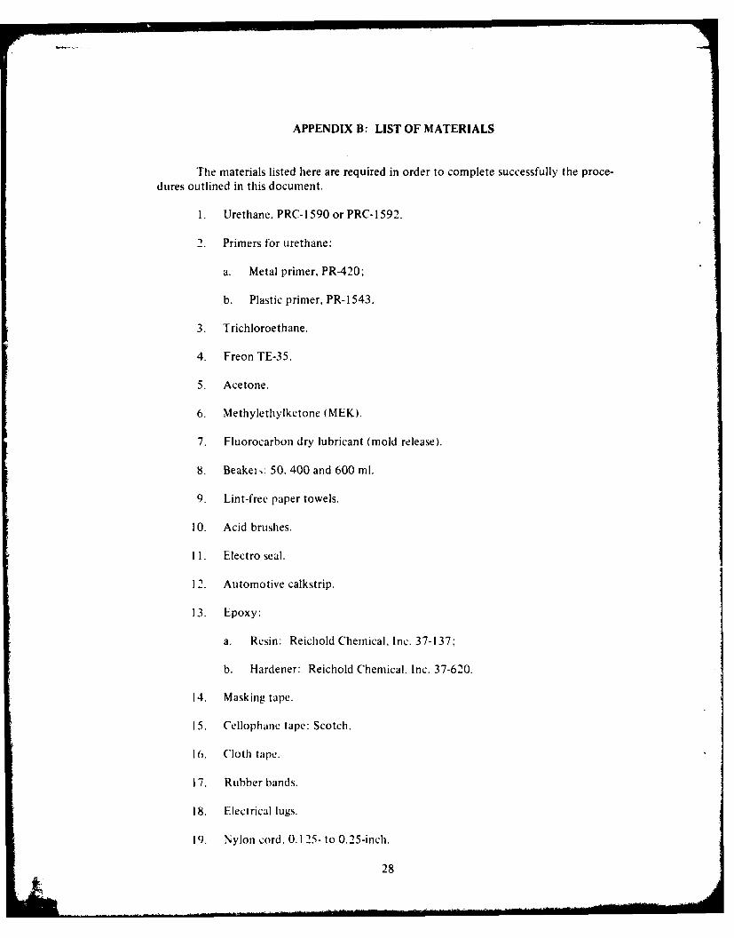
APPENDIX B: LIST OF MATERIALS
The materials listed here are required in order to complete successfully tile proce-dures outlined in this document.
I. Urethane. PRC-1 590 or PRC-1 592.
2. Primers for urethane:
a. Metal primer, PR-420;
b. Plastic primer, PR-1543.
3. Trichloroethane.
4. Freon TE-35.
5. Acetone.
6. Methylethylketone (MEK).
7. Fluorocarbon dry lubricant (mold release).
8. Beakeri: 50, 400 and 600 ml.
9. Lint-free paper towels.
10. Acid brushes.
I1. Electro seal.
12. Automotive calkstrip.
13. Epoxy:
a. Resin: Reichold Chemical, Inc. 37-137:-
b. Hardener: Reichold Chemical, Inc. 37-620.
14. Masking tape.
15. Cellophane tape: Scotch.
16. Cloth tape.
17. Rubber bands.
18. Electrical lugs.
19. Nylon cord. 0. 125- to 0.25-inch.
28

APPENDIX C: LIST OF FIXTURES AND TOOLS
The fixtures and tools listed here are required in order to complete successfullythe procedures outlined in this document.
1. Sky-tower steel scaffolding with work planks.
2. Roll-about safety ladders.
fermination potting fixture stand.
4. Strength termination fixtures:
a. Base plate.
b. Termination cone receiving plate.
c. Bottom spacer tubing.
d. Top plate.
e. Top spacer tubing.
f. Kevlar separator ring.
g. Vertical, fully-threaded rods and nuts, 0.375-inch.
5. Bell jar: plexiglass tube.
6. Bell jar top plate.
7. Vacuum pump with 0.250-inch (6.35-mm) I.D. tygon tubing.
8. Termination cone heating mold.
. Heater.
1 0. Heater elements.
II. Mixin rods.
1 2. Injection mold mUn witi cartridge. ,ap and tips.
13. Thermometer.

APPENDIX D: SOLVENTS AND THEIR USES
Freon tL-35 is used to soak the urethane from the strength member elements. Inaddition. it is used for cleaning in situations where a stronger solvent would cause damage.
Trichlorocthane (chlorethane NU or trichloroethylene) is used to remove the voidfiller compound and some urethane from the strength member elements. Also. it is used forcleaning and degassing. However, caution must be exercised in the latter cases since damageto the conductor insulation can result.
MEK (methylethylketone) is used for cleaning metal parts before the primer isapplied. Its primary use is for thinning the urethane to he used in filling the bubbles.
Acetone is used for cleaning metal parts before the primer is applied. It may be sub-stituted for MIlK for cleaning purposes only.
NOTE
I)o not use acetone as a thinnerfor filling bubbles.
3)

APPEND)IX E: URETHANE METAL PRIMER MIXING INSTRUCTIONS
Material: PR-420 (lProdUcts Research and ('hernical Corporation).
1 horou.lihy mix one part ol'IPart A with six parts of Part B by volumne. Do not mixmore than can be used within a tour-hour period.
Brush1 a thin film of mixed lPR-42O on all inside surfaces 01 connectors and on wire.huit nlot On the insullation. Let the primer dry for one h1our at 75 degrees F (221 degrees C).
If' the primer becomes contain ated. icClean the primled surface lightly withmethiviethylketone M 1K) and dry. Stripping the primer from the connector and reprimingis not necessary.

APPENDIX F: USE OF NONMETALLIC PRIMER
Material: PRC- 1543 (Products Research and Chemlical Corporatioln'.
To obtain good adhiesion. thle surfacte hlud be made tacky with mcvthi 1, tlvlketone(MEK). Apply a thin coat of PR-i1543 to thc tackified Surface by brush and alwto dry for30 minutes at room temperature. If primed surfaces become contaminated tKh -v potting ormolding, buff the primed Surface with a suitable abrasive and reapply a thin -oolFP- .3

APPENDIX G: EPOXY MIXING, DEGASSING AND CURE CYCLE
Materials: Reichold Chemical. Inc. 37-i 27 Resin
Reichold Chemical. Inc. 37-620 Hardener
Mix the resin and hardener. using a ratio of 100 parts resin to 50 parts hardener.
Pour the mix into a beaker having at least twice the capacity of the amount ofepoxy, mixed.
Place the beaker in the vacuun bell jar and evacuate until the mixture begins tobubbl, This cycle may have to be repeated several times.
NOTE
Do not allow the mixture to overflowthe beaker. It may be necessary to closeoff the pump with a valve and allow air toflow back into the bell jar to stop violentbubbling.
N\ ii it is possible to maintain a full vacuuL on the bell jar and only a few smallbubbles it.,nain. the epoxy is outgassed and is ready to be poured into the termination cone.
[poxy may be cured at 77 degrees F (22 degrees C) for 15 hours, or for 4 hours at170 degree., F (08 degrees C).
33

APPENDIX H: URETHANE MIXING, DEGASSING AND CURE CYCLE
Material: PRC-1 590 or 1592 (Products Research and Chemical Corporation).
HEALTH PRECAUTIONS
PRC- 1 590 has proven to be a satfe material to handle when reasonable care is ob-served. Ordinary hygienic principles, such as washing thle compound from thle hands beforeeating or smoking. shouL!d be observed. Hands should be washed with a waterless cleanler.toll1owed by soap and water. Avoid breathing vapors. prolonged contact with thle skinl. conl-tact with open breaks in the skin,. and ingestion.
MIXING INSTRUCTIONS
NOTL
DO no0t open containlers unltilreadv, to use.
Part B solidifies w lien it is kept at tellpIerat ures below 65 degrees 1:i 1 19 degrees(Ii ir prolonged pcriodS. "WlieneCer *his con1ditionl is enlcountered. loosenl thle lid and warm PartBI to 1 210 -, 50 degree,, FI 44,.5 4 ,( dcgrees Ct. Wkhen warming the material. usc a thermometerto determ ine the actual Material ternperatutre. LoieaICf'1t i0I is comp11lete when~ thle mlaterialloses all of, its opaqueness and becomes car. Sit rring is essential during liquefaction to pro-vide a unif'orm material and to hasten imelt ing. Af'ter liquef~taction)I. Part B will remain liquid
At rooml temperatitireI
Part A mav lit partial lv MIC lien -L stre or prolonged periods below 65 degrees [:11) degrees C)1. Wlhenever thlis condionsond. loosen tile lid anld warm Part A to 220 I
10 deg-rees 1: ( 102 ' degreesCC ( i, D~o not1 heat m~er 230 degrees 1: 1 1 1 0 degrees C). When
warming thle Material. useC J t herin LTi)OTr to deCItrmine the act ual material temlperature.11(1 net actionl is colup eItc whenlth I l t~ atridl 1WOMeCS smoo0th anld Li it' form in) appearance andloses all signs of graininess. Stui ring Is essetilal do ing liq nCIet tion to provide a Uniforilima-terial and to hastenl iieht iiic
D)EGASSING INSTRUCTIONS
Pouir mIixedI urethane1 into0 a beaker or beakers having two-thirds greater capacitxhan11 tile amount ot (Iret banev mixed. PI,e the beaker in tile bell jar and evacuate it to a
mnaxiini of' 28,5 in liIg 12'4 mmi I Ig AJlow tile mliX I rC to foaml upJ anld collapse: thenlconltinuke e ac.uiatmig unt1il most (11 tile sn1iI hi bblvs have dis-ippeamreil from tilie surface of'tle urethane1.
34

NOTE
Do not allow the mixture to overflowthe beaker. It may be necessary toclose off tile pump with a valve.allowing air to flow back into thebell jar to stop violent bubbling.
When most of the snall bubbles have been removed, the mixture is ready to b,poured into tile injection gun tubes.
NOTE-
Care should be taken to avoidtrapping any air bubbles whenpouring the mixture into theinjection gun tubes.
CURE CYCLE INSTRUCTIONS
The urethane must be cured at 175 degrees F (80 degrees C(') for 16 hours. Do notcure at a higher temperature. or damage to some materials in the mixture may result.
PHYSICAL PROPERTIES AFTER 16-HOUR CURE (PR-I 590)
Hardness, Shore "A" 75
Specific Gravity 1.08
Volume Shrinkage (Percent) 4
Tensile Strength 3500 psi (247 kg/cln I
Ultimate Elongation. Die "C" 500 percent
Tear Strength, Die "C" 190 lb/in (33.9 kg,/cn)
Adhesion Peel
Aluminum (Primed w/PR-420) 40 lb/il (7.14 kg/cm)
Neoprene (Primed w/PR-1523-M) 25 lb'in (4.40 kg/cnfl
PVC (MEK tackified) 28 lb in S 5.00 kg,'cin)
35

Moisture Absorption I Percent) 2.8
flyvdrolytik: Stability i MSFC-SPFC-202) Coniformis
Elainle Exposure
(ASTM 1) 635: both vertical and
horizontal conf'imurations) Self-extinguishing
3,