C60 Breaker Management Relay - store.gegridsolutions.com · GIS T E R E D LISTED 36GN MEASURING...
320
C60 Breaker Management Relay UR Series Instruction Manual C60 Revision: 2.9X Manual P/N: 1601-0100-B8 (GEK-106376) Copyright ' 2004 GE Multilin g GE Industrial Systems GE Multilin 215 Anderson Avenue, Markham, Ontario Canada L6E 1B3 Tel: (905) 294-6222 Fax: (905) 201-2098 Internet: http://www.GEindustrial.com/multilin Manufactured under an ISO9000 Registered system. R E G I S T E R E D LISTED 36GN MEASURING EQUIP. E200431
Transcript of C60 Breaker Management Relay - store.gegridsolutions.com · GIS T E R E D LISTED 36GN MEASURING...
C60 Breaker Management RelayUR Series Instruction Manual
C60 Revision: 2.9X
Manual P/N: 1601-0100-B8 (GEK-106376)
Copyright © 2004 GE Multilin
gGE Industrial Systems
GE Multilin
215 Anderson Avenue, Markham, Ontario
Canada L6E 1B3
Tel: (905) 294-6222 Fax: (905) 201-2098
Internet: http://www.GEindustrial.com/multilinManufactured under an
ISO9000 Registered system.
R
EG
I S T E R E
D
LISTED
36GN
MEASURING EQUIP.
E200431


gGE Industrial Systems
ADDENDUMThis Addendum contains information that relates to the C60 relay, version 2.9X. This addendum lists a number ofinformation items that appear in the instruction manual GEK-106376 (1601-0100-B8) but are not included in the cur-rent C60 operations.
The following functions/items are not yet available with the current version of the C60 relay:
Signal Sources SRC 5 and SRC 6
NOTE:
The UCA2 specifications are not yet finalized. There will be changes to the object models described in AppendixC: UCA/MMS.
GE Multilin
215 Anderson Avenue, Markham, Ontario
Canada L6E 1B3
Tel: (905) 294-6222 Fax: (905) 201-2098
Internet: http://www.GEindustrial.com/multilin

GE Multilin C60 Breaker Management Relay i
TABLE OF CONTENTS
1. GETTING STARTED 1.1 IMPORTANT PROCEDURES1.1.1 CAUTIONS AND WARNINGS ........................................................................... 1-11.1.2 INSPECTION CHECKLIST ................................................................................ 1-1
1.2 UR OVERVIEW1.2.1 INTRODUCTION TO THE UR RELAY .............................................................. 1-21.2.2 UR HARDWARE ARCHITECTURE................................................................... 1-31.2.3 UR SOFTWARE ARCHITECTURE ................................................................... 1-41.2.4 IMPORTANT UR CONCEPTS........................................................................... 1-4
1.3 URPC® SOFTWARE1.3.1 PC REQUIREMENTS ........................................................................................ 1-51.3.2 SOFTWARE INSTALLATION ............................................................................ 1-51.3.3 CONNECTING URPC® WITH THE C60............................................................ 1-6
1.4 UR HARDWARE1.4.1 MOUNTING AND WIRING................................................................................. 1-81.4.2 COMMUNICATIONS.......................................................................................... 1-81.4.3 FACEPLATE DISPLAY ...................................................................................... 1-8
1.5 USING THE RELAY1.5.1 FACEPLATE KEYPAD....................................................................................... 1-91.5.2 MENU NAVIGATION ......................................................................................... 1-91.5.3 MENU HIERARCHY .......................................................................................... 1-91.5.4 RELAY ACTIVATION....................................................................................... 1-101.5.5 BATTERY TAB................................................................................................. 1-101.5.6 RELAY PASSWORDS ..................................................................................... 1-101.5.7 FLEXLOGIC CUSTOMIZATION................................................................... 1-101.5.8 COMMISSIONING ........................................................................................... 1-10
2. PRODUCT DESCRIPTION 2.1 INTRODUCTION2.1.1 OVERVIEW........................................................................................................ 2-12.1.2 ORDERING........................................................................................................ 2-3
2.2 SPECIFICATIONS2.2.1 PROTECTION ELEMENTS ............................................................................... 2-52.2.2 USER-PROGRAMMABLE ELEMENTS............................................................. 2-62.2.3 MONITORING.................................................................................................... 2-62.2.4 METERING ........................................................................................................ 2-72.2.5 INPUTS .............................................................................................................. 2-72.2.6 POWER SUPPLY .............................................................................................. 2-92.2.7 OUTPUTS .......................................................................................................... 2-92.2.8 COMMUNICATIONS.......................................................................................... 2-92.2.9 ENVIRONMENTAL ............................................................................................ 2-92.2.10 TYPE TESTS ................................................................................................... 2-102.2.11 PRODUCTION TESTS .................................................................................... 2-102.2.12 APPROVALS ................................................................................................... 2-102.2.13 MAINTENANCE ............................................................................................... 2-10
3. HARDWARE 3.1 DESCRIPTION3.1.1 PANEL CUTOUT ............................................................................................... 3-13.1.2 MODULE WITHDRAWAL/INSERTION.............................................................. 3-43.1.3 REAR TERMINAL LAYOUT............................................................................... 3-53.1.4 REAR TERMINAL ASSIGNMENTS................................................................... 3-5
3.2 WIRING3.2.1 TYPICAL WIRING ............................................................................................. 3-63.2.2 DIELECTRIC STRENGTH RATINGS AND TESTING....................................... 3-73.2.3 CONTROL POWER ........................................................................................... 3-73.2.4 CT/VT MODULES .............................................................................................. 3-83.2.5 CONTACT INPUTS/OUTPUTS ....................................................................... 3-103.2.6 TRANSDUCER INPUTS/OUTPUTS............................................................... 3-163.2.7 RS232 FACEPLATE PROGRAM PORT.......................................................... 3-173.2.8 CPU COMMUNICATION PORTS .................................................................... 3-17
ii C60 Breaker Management Relay GE Multilin
TABLE OF CONTENTS
3.2.9 IRIG-B...............................................................................................................3-19
4. HUMAN INTERFACES 4.1 URPC® SOFTWARE INTERFACE4.1.1 GRAPHICAL USER INTERFACE.......................................................................4-14.1.2 CREATING A SITE LIST ....................................................................................4-14.1.3 URPC® SOFTWARE OVERVIEW......................................................................4-14.1.4 URPC® SOFTWARE MAIN WINDOW ...............................................................4-3
4.2 FACEPLATE INTERFACE4.2.1 FACEPLATE.......................................................................................................4-44.2.2 LED INDICATORS..............................................................................................4-54.2.3 CUSTOM LABELING OF LEDs..........................................................................4-74.2.4 CUSTOMIZING THE LED DISPLAY ..................................................................4-74.2.5 DISPLAY.............................................................................................................4-84.2.6 KEYPAD .............................................................................................................4-84.2.7 BREAKER CONTROL ........................................................................................4-94.2.8 MENUS.............................................................................................................4-104.2.9 CHANGING SETTINGS ...................................................................................4-11
5. SETTINGS 5.1 OVERVIEW5.1.1 SETTINGS MAIN MENU ....................................................................................5-15.1.2 INTRODUCTION TO ELEMENTS......................................................................5-35.1.3 INTRODUCTION TO AC SOURCES..................................................................5-4
5.2 PRODUCT SETUP5.2.1 PASSWORD SECURITY....................................................................................5-75.2.2 DISPLAY PROPERTIES ....................................................................................5-85.2.3 COMMUNICATIONS ..........................................................................................5-85.2.4 MODBUS USER MAP ......................................................................................5-155.2.5 REAL TIME CLOCK .........................................................................................5-155.2.6 FAULT REPORT ..............................................................................................5-155.2.7 OSCILLOGRAPHY ...........................................................................................5-165.2.8 DATA LOGGER................................................................................................5-185.2.9 DEMAND ..........................................................................................................5-185.2.10 USER-PROGRAMMABLE LEDS .....................................................................5-205.2.11 FLEX STATE PARAMETERS ..........................................................................5-215.2.12 USER-DEFINABLE DISPLAYS ........................................................................5-215.2.13 INSTALLATION ................................................................................................5-23
5.3 SYSTEM SETUP5.3.1 AC INPUTS.......................................................................................................5-245.3.2 POWER SYSTEM ............................................................................................5-255.3.3 SIGNAL SOURCES..........................................................................................5-265.3.4 LINE..................................................................................................................5-285.3.5 BREAKERS ......................................................................................................5-29
5.4 FLEXLOGIC5.4.1 INTRODUCTION TO FLEXLOGIC................................................................5-325.4.2 FLEXLOGIC RULES .....................................................................................5-375.4.3 FLEXLOGIC EVALUATION ..........................................................................5-385.4.4 FLEXLOGIC PROCEDURE EXAMPLE ........................................................5-385.4.5 FLEXLOGIC EQUATION EDITOR................................................................5-435.4.6 FLEXLOGIC TIMERS ...................................................................................5-435.4.7 FLEXELEMENTS..........................................................................................5-44
5.5 GROUPED ELEMENTS5.5.1 OVERVIEW ......................................................................................................5-485.5.2 SETTING GROUP ............................................................................................5-485.5.3 BREAKER FAILURE ........................................................................................5-485.5.4 VOLTAGE ELEMENTS ....................................................................................5-58
5.6 CONTROL ELEMENTS5.6.1 OVERVIEW ......................................................................................................5-625.6.2 SETTING GROUPS..........................................................................................5-625.6.3 SYNCHROCHECK ...........................................................................................5-63
GE Multilin C60 Breaker Management Relay iii
TABLE OF CONTENTS
5.6.4 AUTORECLOSE .............................................................................................. 5-675.6.5 DIGITAL ELEMENTS....................................................................................... 5-785.6.6 DIGITAL COUNTERS ...................................................................................... 5-815.6.7 MONITORING ELEMENTS ............................................................................. 5-83
5.7 INPUTS / OUTPUTS5.7.1 CONTACT INPUTS.......................................................................................... 5-855.7.2 VIRTUAL INPUTS............................................................................................ 5-875.7.3 UCA SBO TIMER............................................................................................. 5-885.7.4 CONTACT OUTPUTS...................................................................................... 5-885.7.5 VIRTUAL OUTPUTS........................................................................................ 5-895.7.6 REMOTE DEVICES ......................................................................................... 5-895.7.7 REMOTE INPUTS............................................................................................ 5-905.7.8 REMOTE OUTPUTS: DNA BIT PAIRS............................................................ 5-915.7.9 REMOTE OUTPUTS: UserSt BIT PAIRS ........................................................ 5-925.7.10 RESETTING..................................................................................................... 5-92
5.8 TRANSDUCER I/O5.8.1 DCMA INPUTS ................................................................................................ 5-935.8.2 RTD INPUTS.................................................................................................... 5-94
5.9 TESTING5.9.1 TEST MODE .................................................................................................... 5-955.9.2 FORCE CONTACT INPUTS ............................................................................ 5-955.9.3 FORCE CONTACT OUTPUTS ........................................................................ 5-95
6. ACTUAL VALUES 6.1 OVERVIEW6.1.1 ACTUAL VALUES MAIN MENU ........................................................................ 6-1
6.2 STATUS6.2.1 CONTACT INPUTS............................................................................................ 6-36.2.2 VIRTUAL INPUTS.............................................................................................. 6-36.2.3 REMOTE INPUTS.............................................................................................. 6-36.2.4 CONTACT OUTPUTS........................................................................................ 6-46.2.5 VIRTUAL OUTPUTS.......................................................................................... 6-46.2.6 AUTORECLOSE ................................................................................................ 6-46.2.7 REMOTE DEVICES STATUS............................................................................ 6-46.2.8 REMOTE DEVICES STATISTICS ..................................................................... 6-56.2.9 DIGITAL COUNTERS ........................................................................................ 6-56.2.10 FLEX STATES ................................................................................................... 6-56.2.11 ETHERNET........................................................................................................ 6-5
6.3 METERING6.3.1 METERING CONVENTIONS............................................................................. 6-66.3.2 SOURCES ......................................................................................................... 6-96.3.3 SYNCHROCHECK........................................................................................... 6-126.3.4 TRACKING FREQUENCY ............................................................................... 6-136.3.5 FLEXELEMENTS ......................................................................................... 6-136.3.6 TRANSDUCER I/O .......................................................................................... 6-13
6.4 RECORDS6.4.1 FAULT REPORTS ........................................................................................... 6-146.4.2 FAULT LOCATOR OPERATION ..................................................................... 6-146.4.3 EVENT RECORDS .......................................................................................... 6-166.4.4 OSCILLOGRAPHY .......................................................................................... 6-166.4.5 DATA LOGGER ............................................................................................... 6-166.4.6 MAINTENANCE ............................................................................................... 6-17
6.5 PRODUCT INFORMATION6.5.1 MODEL INFORMATION .................................................................................. 6-186.5.2 FIRMWARE REVISIONS ................................................................................. 6-18
7. COMMANDS AND TARGETS
7.1 COMMANDS7.1.1 COMMANDS MENU .......................................................................................... 7-17.1.2 VIRTUAL INPUTS.............................................................................................. 7-1
iv C60 Breaker Management Relay GE Multilin
TABLE OF CONTENTS
7.1.3 CLEAR RECORDS.............................................................................................7-17.1.4 SET DATE AND TIME ........................................................................................7-27.1.5 RELAY MAINTENANCE.....................................................................................7-2
7.2 TARGETS7.2.1 TARGETS MENU ...............................................................................................7-37.2.2 TARGET MESSAGES ........................................................................................7-37.2.3 RELAY SELF-TESTS .........................................................................................7-3
8. COMMISSIONING 8.1 PRODUCT SETUP8.1.1 SETTINGS..........................................................................................................8-1
8.2 SYSTEM SETUP8.2.1 SETTINGS..........................................................................................................8-8
8.3 FLEXLOGIC8.3.1 SETTINGS........................................................................................................8-10
8.4 GROUPED ELEMENTS8.4.1 SETTINGS........................................................................................................8-19
8.5 CONTROL ELEMENTS8.5.1 SETTINGS........................................................................................................8-21
8.6 INPUTS / OUTPUTS8.6.1 CONTACT INPUTS ..........................................................................................8-258.6.2 VIRTUAL INPUTS ............................................................................................8-268.6.3 UCA SBO TIMER .............................................................................................8-268.6.4 REMOTE DEVICES..........................................................................................8-278.6.5 REMOTE INPUTS ............................................................................................8-288.6.6 CONTACT OUTPUTS ......................................................................................8-298.6.7 VIRTUAL OUTPUTS ........................................................................................8-308.6.8 REMOTE OUTPUTS ........................................................................................8-318.6.9 RESETTING .....................................................................................................8-31
8.7 TRANSDUCER I/O8.7.1 DCMA INPUTS .................................................................................................8-328.7.2 RTD INPUTS ....................................................................................................8-33
8.8 TESTING8.8.1 SETTINGS........................................................................................................8-34
A. FLEXANALOG PARAMETERS
A.1 FLEXANALOG PARAMETER LIST
B. MODBUS® RTU PROTOCOL B.1 OVERVIEWB.1.1 INTRODUCTION ............................................................................................... B-1B.1.2 PHYSICAL LAYER ............................................................................................ B-1B.1.3 DATA LINK LAYER ........................................................................................... B-1B.1.4 CRC-16 ALGORITHM ....................................................................................... B-3
0.1 FUNCTION CODESB.1.5 SUPPORTED FUNCTION CODES ................................................................... B-4B.1.6 FUNCTION CODE 03H/04H: READ ACTUAL VALUES OR SETTINGS.......... B-4B.1.7 FUNCTION CODE 05H: EXECUTE OPERATION ............................................ B-5B.1.8 FUNCTION CODE 06H: STORE SINGLE SETTING ........................................ B-5B.1.9 FUNCTION CODE 10H: STORE MULTIPLE SETTINGS ................................. B-6B.1.10 EXCEPTION RESPONSES............................................................................... B-6
B.2 FILE TRANSFERSB.2.1 OBTAINING UR FILES USING MODBUS® PROTOCOL ................................. B-7B.2.2 MODBUS® PASSWORD OPERATION............................................................. B-8
B.3 MEMORY MAPPINGB.3.1 MODBUS® MEMORY MAP............................................................................... B-9
GE Multilin C60 Breaker Management Relay v
TABLE OF CONTENTS
B.3.2 MODBUS® MEMORY MAP DATA FORMATS ................................................B-38
C. UCA/MMS C.1 UCA/MMS OVERVIEWC.1.1 UCA....................................................................................................................C-1C.1.2 MMS...................................................................................................................C-1C.1.3 UCA REPORTING .............................................................................................C-6
D. IEC 60870-5-104 D.1 IEC 60870-5-104 PROTOCOLD.1.1 INTEROPERABILITY DOCUMENT ...................................................................D-1D.1.2 POINTS LIST ...................................................................................................D-10
E. DNP E.1 DNP DEVICE PROFILEE.1.1 DNP V3.00 DEVICE PROFILE ..........................................................................E-1
E.2 DNP IMPLEMENTATION TABLEE.2.1 IMPLEMENTATION TABLE...............................................................................E-4
E.3 DNP POINT LISTSE.3.1 BINARY INPUT POINTS....................................................................................E-8E.3.2 BINARY OUTPUT AND CONTROL RELAY OUTPUT ....................................E-13E.3.3 COUNTERS .....................................................................................................E-14E.3.4 ANALOG INPUTS ............................................................................................E-15
F. MISCELLANEOUS F.1 CHANGE NOTESF.1.1 REVISION HISTORY ......................................................................................... F-1F.1.2 CHANGES TO C60 MANUAL............................................................................ F-1
F.2 TABLES AND FIGURESF.2.1 LIST OF TABLES............................................................................................... F-3F.2.2 LIST OF FIGURES............................................................................................. F-4
F.3 ABBREVIATIONSF.3.1 STANDARD ABBREVIATIONS ......................................................................... F-6
F.4 WARRANTYF.4.1 GE POWER MANAGEMENT WARRANTY ....................................................... F-8
INDEX

vi C60 Breaker Management Relay GE Multilin
TABLE OF CONTENTS
GE Multilin C60 Breaker Management Relay 1-1
1 GETTING STARTED 1.1 IMPORTANT PROCEDURES
11 GETTING STARTED 1.1 IMPORTANT PROCEDURES
Please read this chapter to help guide you through the initial setup of your new relay.
1.1.1 CAUTIONS AND WARNINGS
Before attempting to install or use the relay, it is imperative that all WARNINGS and CAU-TIONS in this manual are reviewed to help prevent personal injury, equipment damage, and/or downtime.
1.1.2 INSPECTION CHECKLIST
Open the relay packaging and inspect the unit for physical damage.
Check that the battery tab is intact on the power supply module (for more details, see the section BATTERY TAB in thischapter).
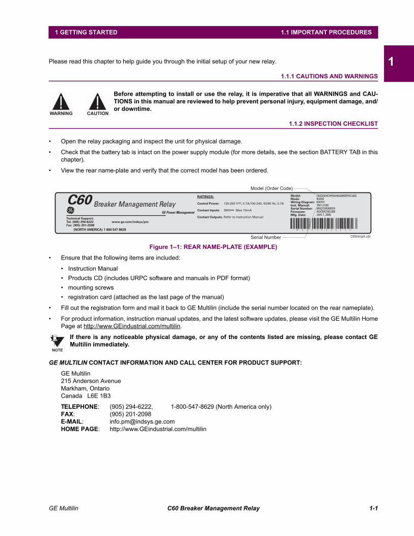
View the rear name-plate and verify that the correct model has been ordered.
Figure 11: REAR NAME-PLATE (EXAMPLE)
Ensure that the following items are included:
Instruction Manual Products CD (includes URPC software and manuals in PDF format) mounting screws registration card (attached as the last page of the manual)
Fill out the registration form and mail it back to GE Multilin (include the serial number located on the rear nameplate).
For product information, instruction manual updates, and the latest software updates, please visit the GE Multilin HomePage at http://www.GEindustrial.com/multilin.
If there is any noticeable physical damage, or any of the contents listed are missing, please contact GEMultilin immediately.
GE MULTILIN CONTACT INFORMATION AND CALL CENTER FOR PRODUCT SUPPORT:
GE Multilin215 Anderson AvenueMarkham, OntarioCanada L6E 1B3
TELEPHONE: (905) 294-6222, 1-800-547-8629 (North America only)FAX: (905) 201-2098E-MAIL: [email protected] PAGE: http://www.GEindustrial.com/multilin
WARNING CAUTION
NOTE
1-2 C60 Breaker Management Relay GE Multilin
1.2 UR OVERVIEW 1 GETTING STARTED
11.2 UR OVERVIEW 1.2.1 INTRODUCTION TO THE UR RELAY
Historically, substation protection, control, and metering functions were performed with electromechanical equipment. Thisfirst generation of equipment was gradually replaced by analog electronic equipment, most of which emulated the single-function approach of their electromechanical precursors. Both of these technologies required expensive cabling and auxil-iary equipment to produce functioning systems.
Recently, digital electronic equipment has begun to provide protection, control, and metering functions. Initially, this equip-ment was either single function or had very limited multi-function capability, and did not significantly reduce the cabling andauxiliary equipment required. However, recent digital relays have become quite multi-functional, reducing cabling and aux-iliaries significantly. These devices also transfer data to central control facilities and Human Machine Interfaces using elec-tronic communications. The functions performed by these products have become so broad that many users now prefer theterm IED (Intelligent Electronic Device).
It is obvious to station designers that the amount of cabling and auxiliary equipment installed in stations can be even furtherreduced, to 20% to 70% of the levels common in 1990, to achieve large cost reductions. This requires placing even morefunctions within the IEDs.
Users of power equipment are also interested in reducing cost by improving power quality and personnel productivity, andas always, in increasing system reliability and efficiency. These objectives are realized through software which is used toperform functions at both the station and supervisory levels. The use of these systems is growing rapidly.
High speed communications are required to meet the data transfer rates required by modern automatic control and moni-toring systems. In the near future, very high speed communications will be required to perform protection signaling with aperformance target response time for a command signal between two IEDs, from transmission to reception, of less than 5milliseconds. This has been established by the Electric Power Research Institute, a collective body of many American andCanadian power utilities, in their Utilities Communications Architecture 2 (MMS/UCA2) project. In late 1998, some Euro-pean utilities began to show an interest in this ongoing initiative.
IEDs with the capabilities outlined above will also provide significantly more power system data than is presently available,enhance operations and maintenance, and permit the use of adaptive system configuration for protection and control sys-tems. This new generation of equipment must also be easily incorporated into automation systems, at both the station andenterprise levels. The GE Multilin Universal Relay (UR) has been developed to meet these goals.
GE Multilin C60 Breaker Management Relay 1-3
1 GETTING STARTED 1.2 UR OVERVIEW
11.2.2 UR HARDWARE ARCHITECTURE
Figure 12: UR CONCEPT BLOCK DIAGRAM
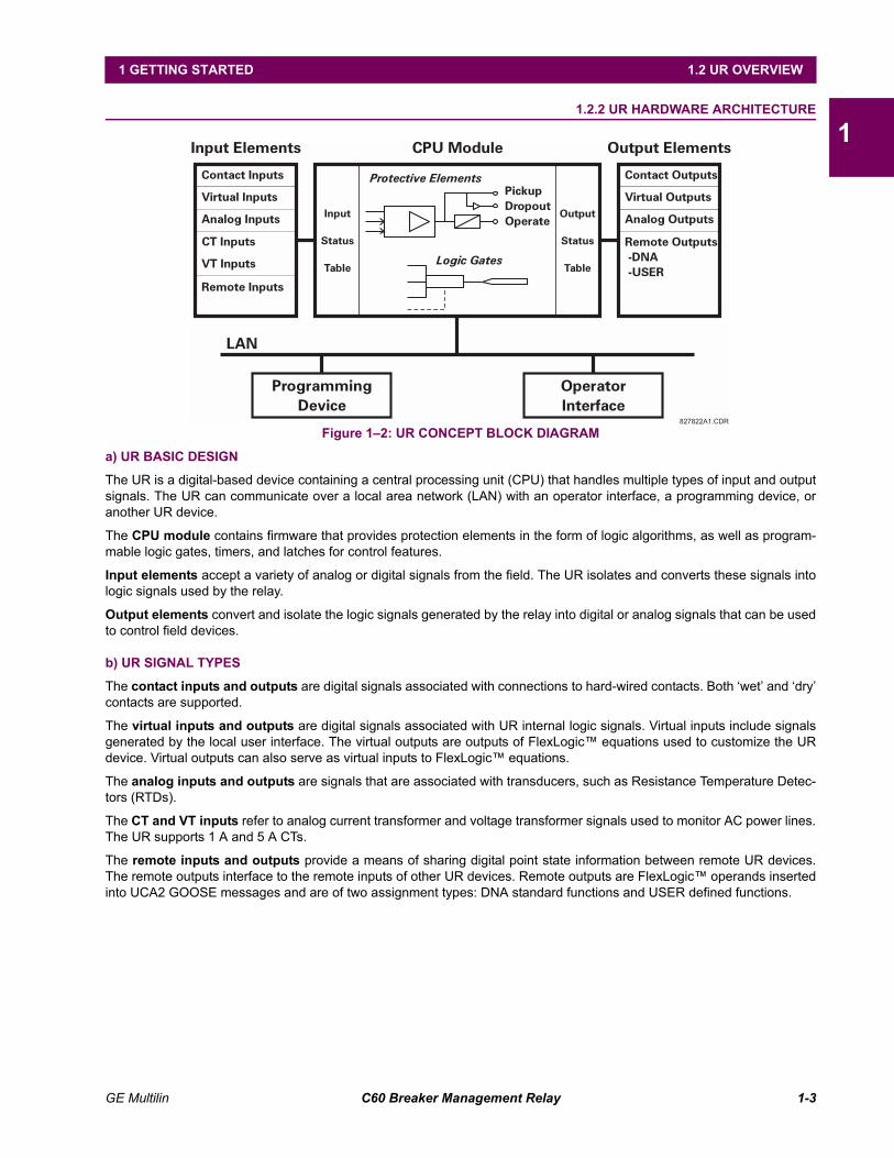
a) UR BASIC DESIGN
The UR is a digital-based device containing a central processing unit (CPU) that handles multiple types of input and outputsignals. The UR can communicate over a local area network (LAN) with an operator interface, a programming device, oranother UR device.
The CPU module contains firmware that provides protection elements in the form of logic algorithms, as well as program-mable logic gates, timers, and latches for control features.
Input elements accept a variety of analog or digital signals from the field. The UR isolates and converts these signals intologic signals used by the relay.
Output elements convert and isolate the logic signals generated by the relay into digital or analog signals that can be usedto control field devices.
b) UR SIGNAL TYPES
The contact inputs and outputs are digital signals associated with connections to hard-wired contacts. Both wet and drycontacts are supported.
The virtual inputs and outputs are digital signals associated with UR internal logic signals. Virtual inputs include signalsgenerated by the local user interface. The virtual outputs are outputs of FlexLogic equations used to customize the URdevice. Virtual outputs can also serve as virtual inputs to FlexLogic equations.
The analog inputs and outputs are signals that are associated with transducers, such as Resistance Temperature Detec-tors (RTDs).
The CT and VT inputs refer to analog current transformer and voltage transformer signals used to monitor AC power lines.The UR supports 1 A and 5 A CTs.
The remote inputs and outputs provide a means of sharing digital point state information between remote UR devices.The remote outputs interface to the remote inputs of other UR devices. Remote outputs are FlexLogic operands insertedinto UCA2 GOOSE messages and are of two assignment types: DNA standard functions and USER defined functions.
827822A1.CDR
Input Elements
LAN
ProgrammingDevice
OperatorInterface
Contact Inputs Contact Outputs
Virtual Inputs Virtual Outputs
Analog Inputs Analog Outputs
CT Inputs
VT Inputs
Input
Status
Table
Output
Status
Table
PickupDropoutOperate
Protective Elements
Logic Gates
Remote Inputs
Remote Outputs-DNA-USER
CPU Module Output Elements
1-4 C60 Breaker Management Relay GE Multilin
1.2 UR OVERVIEW 1 GETTING STARTED
1c) UR SCAN OPERATION
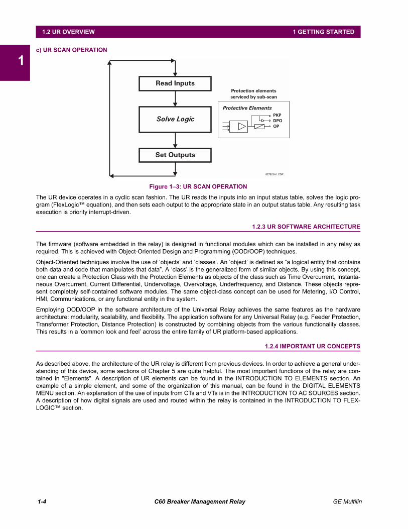
Figure 13: UR SCAN OPERATION
The UR device operates in a cyclic scan fashion. The UR reads the inputs into an input status table, solves the logic pro-gram (FlexLogic equation), and then sets each output to the appropriate state in an output status table. Any resulting taskexecution is priority interrupt-driven.
1.2.3 UR SOFTWARE ARCHITECTURE
The firmware (software embedded in the relay) is designed in functional modules which can be installed in any relay asrequired. This is achieved with Object-Oriented Design and Programming (OOD/OOP) techniques.
Object-Oriented techniques involve the use of objects and classes. An object is defined as a logical entity that containsboth data and code that manipulates that data. A class is the generalized form of similar objects. By using this concept,one can create a Protection Class with the Protection Elements as objects of the class such as Time Overcurrent, Instanta-neous Overcurrent, Current Differential, Undervoltage, Overvoltage, Underfrequency, and Distance. These objects repre-sent completely self-contained software modules. The same object-class concept can be used for Metering, I/O Control,HMI, Communications, or any functional entity in the system.
Employing OOD/OOP in the software architecture of the Universal Relay achieves the same features as the hardwarearchitecture: modularity, scalability, and flexibility. The application software for any Universal Relay (e.g. Feeder Protection,Transformer Protection, Distance Protection) is constructed by combining objects from the various functionality classes.This results in a common look and feel across the entire family of UR platform-based applications.
1.2.4 IMPORTANT UR CONCEPTS
As described above, the architecture of the UR relay is different from previous devices. In order to achieve a general under-standing of this device, some sections of Chapter 5 are quite helpful. The most important functions of the relay are con-tained in "Elements". A description of UR elements can be found in the INTRODUCTION TO ELEMENTS section. Anexample of a simple element, and some of the organization of this manual, can be found in the DIGITAL ELEMENTSMENU section. An explanation of the use of inputs from CTs and VTs is in the INTRODUCTION TO AC SOURCES section.A description of how digital signals are used and routed within the relay is contained in the INTRODUCTION TO FLEX-LOGIC section.
827823A1.CDR
PKPDPOOP
Protective Elements
Protection elementsserviced by sub-scan
Read Inputs
Solve Logic
Set Outputs
GE Multilin C60 Breaker Management Relay 1-5
1 GETTING STARTED 1.3 URPC® SOFTWARE
11.3 URPC® SOFTWARE 1.3.1 PC REQUIREMENTS
The Faceplate keypad and display or the URPC software interface can be used to communicate with the relay.
The URPC software interface is the preferred method to edit settings and view actual values because the PC monitor candisplay more information in a simple comprehensible format.
The following minimum requirements must be met for the URPC software to properly operate on a PC.
Processor: Intel® Pentium 300 or higher
RAM Memory: 64 MB minimum (128 MB recommended)
Hard Disk: 50 MB free space required before installation of URPC software
O/S: Windows® NT 4.x or Windows® 9x/2000
Device: CD-ROM drive
Port: COM1(2) / Ethernet
1.3.2 SOFTWARE INSTALLATION
Refer to the following procedure to install the URPC software:
1. Start the Windows® operating system.
2. Insert the URPC software CD into the CD-ROM drive.
3. If the installation program does not start automatically, choose Run from the Windows® Start menu and typeD:\SETUP.EXE. Press Enter to start the installation.
4. Follow the on-screen instructions to install the URPC software. When the Welcome window appears, click on Next tocontinue with the installation procedure.
5. When the Choose Destination Location window appears and if the software is not to be located in the default direc-tory, click Browse and type in the complete path name including the new directory name.
6. Click Next to continue with the installation procedure.
7. The default program group where the application will be added to is shown in the Select Program Folder window. If itis desired that the application be added to an already existing program group, choose the group name from the listshown.
8. Click Next to begin the installation process.
9. To launch the URPC application, click Finish in the Setup Complete window.
10. Subsequently, double click on the URPC software icon to activate the application.
Refer to the HUMAN INTERFACES chapter in this manual and the URPC Software Help program for moreinformation about the URPC software interface.
NOTE
1-6 C60 Breaker Management Relay GE Multilin
1.3 URPC® SOFTWARE 1 GETTING STARTED
11.3.3 CONNECTING URPC® WITH THE C60
This section is intended as a quick start guide to using the URPC software. Please refer to the URPC Help File and theHUMAN INTERFACES chapter for more information.
a) CONFIGURING AN ETHERNET CONNECTION
Before starting, verify that the Ethernet network cable is properly connected to the Ethernet port on the back of the relay.
1. Start the URPC software. Enter the password "URPC" at the login password box.
2. Select the Help > Connection Wizard menu item to open the Connection Wizard. Click "Next" to continue.
3. Click the "New Interface" button to open the Edit New Interface window.
Enter the desired interface name in the Enter Interface Name field.
Select the "Ethernet" interface from the drop down list and press "Next" to continue.
4. Click the "New Device" button to open the Edit New Device Window.
Enter the desired name in the Enter Interface Name field.
Enter the Modbus address of the relay (from SETTINGS ! PRODUCT SETUP !" COMMUNICATIONS !" MODBUSPROTOCOL ! MODBUS SLAVE ADDRESS) in the Enter Modbus Address field.
Enter the IP address (from SETTINGS ! PRODUCT SETUP !" COMMUNICATIONS !" NETWORK ! IP ADDRESS) inthe Enter TCPIP Address field.
5. Click the "4.1 Read Device Information" button then "OK" when the relay information has been received. Click "Next" tocontinue.
6. Click the "New Site" button to open the Edit Site Name window.
Enter the desired site name in the Enter Site Name field.
7. Click the "OK" button then click "Finish". The new Site List tree will be added to the Site List window (or Online window)located in the top left corner of the main URPC window.
The Site Device has now been configured for Ethernet communications. Proceed to Section c) CONNECTING TO THERELAY below to begin communications.
b) CONFIGURING AN RS232 CONNECTION
Before starting, verify that the RS232 serial cable is properly connected to the RS232 port on the front panel of the relay.
1. Start the URPC software. Enter the password "URPC" at the login password box.
2. Select the Help > Connection Wizard menu item to open the Connection Wizard. Click "Next" to continue.
3. Click the "New Interface" button to open the Edit New Interface window.
Enter the desired interface name in the Enter Interface Name field.
Select the "RS232" interface from the drop down list and press "Next" to continue.
4. Click the "New Device" button to open the Edit New Device Window.
Enter the desired name in the Enter Interface Name field.
Enter the PC COM port number in the COM Port field.
5. Click "OK" then click "Next" to continue.
6. Click the "New Site" button to open the Edit Site Name window.
Enter the desired site name in the Enter Site Name field.
7. Click the "OK" button then click "Finish". The new Site List tree will be added to the Site List window (or Online window)located in the top left corner of the main URPC window.
The Site Device has now been configured for RS232 communications. Proceed to Section c) CONNECTING TO THERELAY below to begin communications.
GE Multilin C60 Breaker Management Relay 1-7
1 GETTING STARTED 1.3 URPC® SOFTWARE
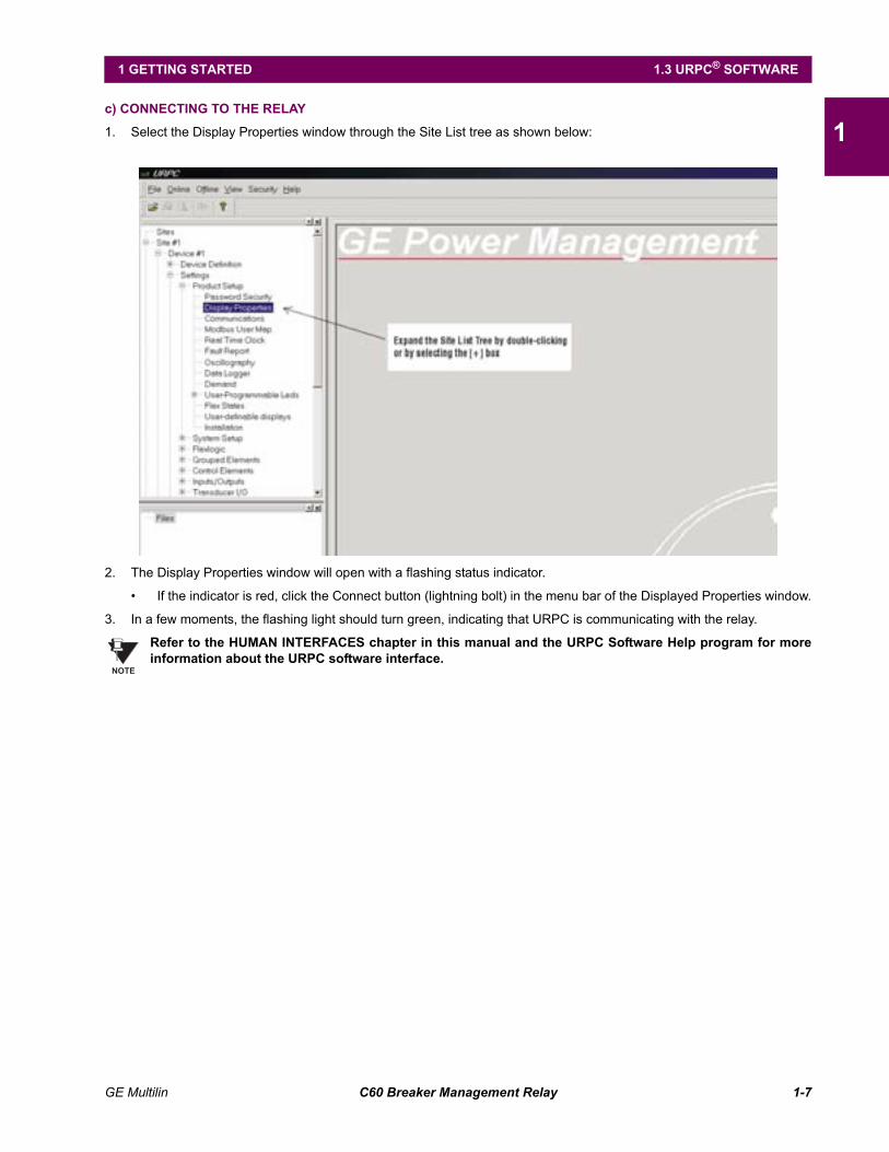
1c) CONNECTING TO THE RELAY
1. Select the Display Properties window through the Site List tree as shown below:
2. The Display Properties window will open with a flashing status indicator.
If the indicator is red, click the Connect button (lightning bolt) in the menu bar of the Displayed Properties window.
3. In a few moments, the flashing light should turn green, indicating that URPC is communicating with the relay.
Refer to the HUMAN INTERFACES chapter in this manual and the URPC Software Help program for moreinformation about the URPC software interface.
NOTE
1-8 C60 Breaker Management Relay GE Multilin
1.4 UR HARDWARE 1 GETTING STARTED
11.4 UR HARDWARE 1.4.1 MOUNTING AND WIRING
Please refer to the HARDWARE chapter for detailed relay mounting and wiring instructions. Review all WARNINGS andCAUTIONS.
1.4.2 COMMUNICATIONS
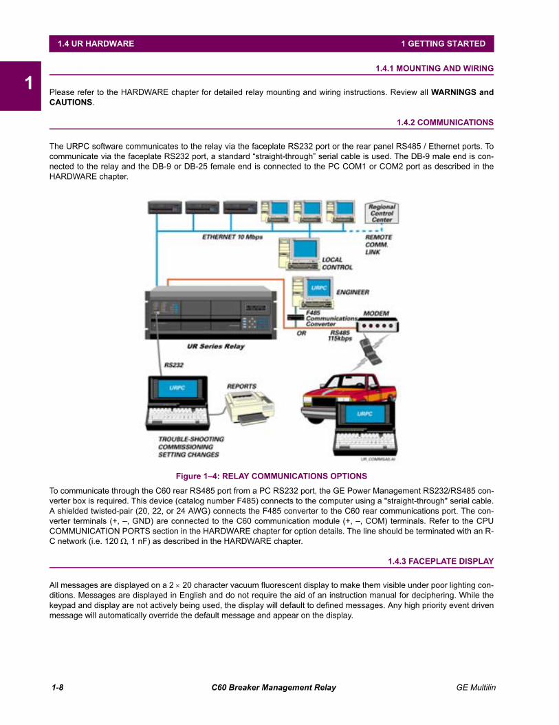
The URPC software communicates to the relay via the faceplate RS232 port or the rear panel RS485 / Ethernet ports. Tocommunicate via the faceplate RS232 port, a standard straight-through serial cable is used. The DB-9 male end is con-nected to the relay and the DB-9 or DB-25 female end is connected to the PC COM1 or COM2 port as described in theHARDWARE chapter.
Figure 14: RELAY COMMUNICATIONS OPTIONS
To communicate through the C60 rear RS485 port from a PC RS232 port, the GE Power Management RS232/RS485 con-verter box is required. This device (catalog number F485) connects to the computer using a "straight-through" serial cable.A shielded twisted-pair (20, 22, or 24 AWG) connects the F485 converter to the C60 rear communications port. The con-verter terminals (+, , GND) are connected to the C60 communication module (+, , COM) terminals. Refer to the CPUCOMMUNICATION PORTS section in the HARDWARE chapter for option details. The line should be terminated with an R-C network (i.e. 120 Ω, 1 nF) as described in the HARDWARE chapter.
1.4.3 FACEPLATE DISPLAY
All messages are displayed on a 2 × 20 character vacuum fluorescent display to make them visible under poor lighting con-ditions. Messages are displayed in English and do not require the aid of an instruction manual for deciphering. While thekeypad and display are not actively being used, the display will default to defined messages. Any high priority event drivenmessage will automatically override the default message and appear on the display.

GE Multilin C60 Breaker Management Relay 1-9
1 GETTING STARTED 1.5 USING THE RELAY
11.5 USING THE RELAY 1.5.1 FACEPLATE KEYPAD
Display messages are organized into pages under the following headings: Actual Values, Settings, Commands, and Tar-gets. The key navigates through these pages. Each heading page is broken down further into logical subgroups.
The MESSAGE keys navigate through the subgroups. The VALUE keys scroll increment or decrementnumerical setting values when in programming mode. These keys also scroll through alphanumeric values in the text editmode. Alternatively, values may also be entered with the numeric keypad.
The key initiates and advance to the next character in text edit mode or enters a decimal point. The key may bepressed at any time for context sensitive help messages. The key stores altered setting values.
1.5.2 MENU NAVIGATION
Press the key to select the desired header display page (top-level menu). The header title appears momentarily fol-lowed by a header display page menu item. Each press of the key advances through the main heading pages asillustrated below.
1.5.3 MENU HIERARCHY
The setting and actual value messages are arranged hierarchically. The header display pages are indicated by doublescroll bar characters (##), while sub-header pages are indicated by single scroll bar characters (#). The header displaypages represent the highest level of the hierarchy and the sub-header display pages fall below this level. The MESSAGE
and keys move within a group of headers, sub-headers, setting values, or actual values. Continually pressing theMESSAGE key from a header display displays specific information for the header category. Conversely, continuallypressing the MESSAGE key from a setting value or actual value display returns to the header display.
! ! !
ACTUAL VALUES SETTINGS COMMANDS TARGETS
" " " "
## ACTUAL VALUES## STATUS
## SETTINGS## PRODUCT SETUP
## COMMANDS## VIRTUAL INPUTS
No ActiveTargets
!
USER DISPLAYS(when in use)
"
User Display 1
HIGHEST LEVEL LOWEST LEVEL (SETTING VALUE)
## SETTINGS## PRODUCT SETUP
# PASSWORD# SECURITY
ACCESS LEVEL:Restricted
## SETTINGS## SYSTEM SETUP
1-10 C60 Breaker Management Relay GE Multilin
1.5 USING THE RELAY 1 GETTING STARTED
11.5.4 RELAY ACTIVATION
The relay is defaulted to the "Not Programmed" state when it leaves the factory. This safeguards against the installation ofa relay whose settings have not been entered. When powered up successfully, the TROUBLE indicator will be on and theIN SERVICE indicator off. The relay in the "Not Programmed" state will block signaling of any output relay. These condi-tions will remain until the relay is explicitly put in the "Programmed" state.
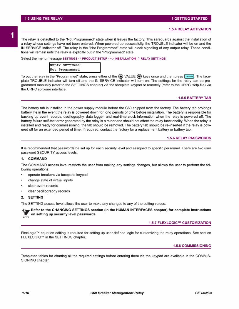
Select the menu message SETTINGS ! PRODUCT SETUP !" INSTALLATION ! RELAY SETTINGS
To put the relay in the "Programmed" state, press either of the VALUE keys once and then press . The face-plate TROUBLE indicator will turn off and the IN SERVICE indicator will turn on. The settings for the relay can be pro-grammed manually (refer to the SETTINGS chapter) via the faceplate keypad or remotely (refer to the URPC Help file) viathe URPC software interface.
1.5.5 BATTERY TAB
The battery tab is installed in the power supply module before the C60 shipped from the factory. The battery tab prolongsbattery life in the event the relay is powered down for long periods of time before installation. The battery is responsible forbacking up event records, oscillography, data logger, and real-time clock information when the relay is powered off. Thebattery failure self-test error generated by the relay is a minor and should not affect the relay functionality. When the relay isinstalled and ready for commissioning, the tab should be removed. The battery tab should be re-inserted if the relay is pow-ered off for an extended period of time. If required, contact the factory for a replacement battery or battery tab.
1.5.6 RELAY PASSWORDS
It is recommended that passwords be set up for each security level and assigned to specific personnel. There are two userpassword SECURITY access levels:
1. COMMAND
The COMMAND access level restricts the user from making any settings changes, but allows the user to perform the fol-lowing operations: operate breakers via faceplate keypad change state of virtual inputs clear event records clear oscillography records
2. SETTING
The SETTING access level allows the user to make any changes to any of the setting values.
Refer to the CHANGING SETTINGS section (in the HUMAN INTERFACES chapter) for complete instructionson setting up security level passwords.
1.5.7 FLEXLOGIC CUSTOMIZATION
FlexLogic equation editing is required for setting up user-defined logic for customizing the relay operations. See sectionFLEXLOGIC in the SETTINGS chapter.
1.5.8 COMMISSIONING
Templated tables for charting all the required settings before entering them via the keypad are available in the COMMIS-SIONING chapter.
RELAY SETTINGS:Not Programmed
NOTE
GE Multilin C60 Breaker Management Relay 2-1
2 PRODUCT DESCRIPTION 2.1 INTRODUCTION
2
2 PRODUCT DESCRIPTION 2.1 INTRODUCTION 2.1.1 OVERVIEW
The C60 Breaker Management Relay is a microprocessor based relay designed for breaker monitoring, control and protec-tion.
Voltage and current metering is built into the relay as a standard feature. Current parameters are available as total wave-form RMS magnitude, or as fundamental frequency only RMS magnitude and angle (phasor).
The internal clock used for time-tagging can be synchronized with an IRIG-B signal. This precise time stamping allows thesequence of events to be determined throughout the system. Events can also be programmed (via FlexLogic equations)to trigger oscillography data capture which may be set to record the measured parameters before and after the event forviewing on a personal computer (PC). These tools significantly reduce troubleshooting time and simplify report generationin the event of a system fault.
A faceplate RS232 port may be used to connect to a PC for the programming of settings and the monitoring of actual val-ues. A variety of communications modules are available. Two rear RS485 ports allow independent access by operating andengineering staff. All serial ports use the Modbus® RTU protocol. The RS485 ports may be connected to system computerswith baud rates up to 115.2 kbps. The RS232 port has a fixed baud rate of 19.2 kbps. Optional communications modulesinclude a 10BaseF Ethernet interface which can be used to provide fast, reliable communications in noisy environments.Another option provides two 10BaseF fiber optic ports for redundancy. The Ethernet port supports MMS/UCA2, Modbus®/TCP, and TFTP protocols, and allows access to the relay via any standard web browser (UR web pages). The DNP 3.0 orIEC 60870-5-104 protocol is supported on a user-specified port, including serial and Ethernet ports.
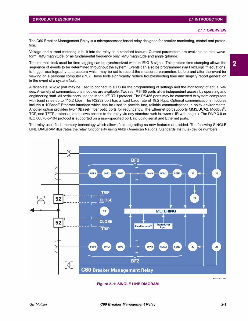
The relay uses flash memory technology which allows field upgrading as new features are added. The following SINGLELINE DIAGRAM illustrates the relay functionality using ANSI (American National Standards Institute) device numbers.
Figure 21: SINGLE LINE DIAGRAM834710AA.CDR
C60 Breaker Management Relay
BF2
BF2
METERING
CLOSE
CLOSE
TRIP
TRIP
FlexElementTM TransducerInput
79
27
27
27
25
2550P1 50P2 50P3 50N1 50N2 50N3
50P1 50N150P2 50N250P3 50N3
52
52
2-2 C60 Breaker Management Relay GE Multilin
2.1 INTRODUCTION 2 PRODUCT DESCRIPTION
2
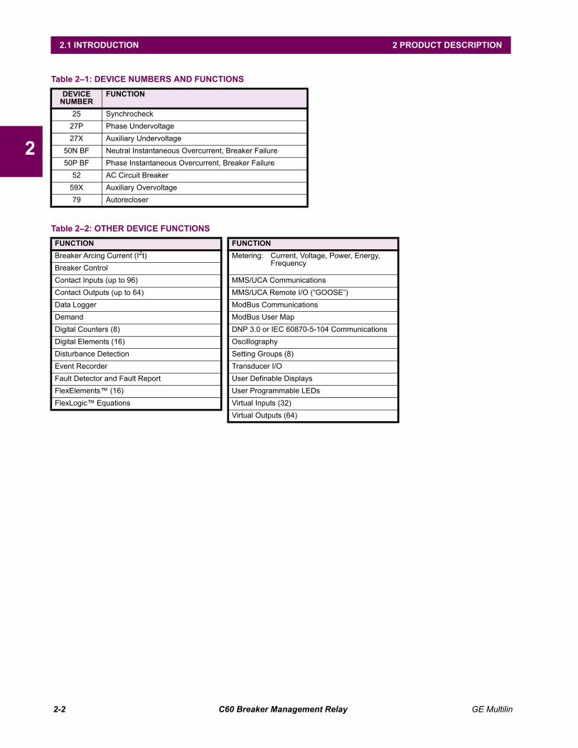
Table 21: DEVICE NUMBERS AND FUNCTIONSDEVICE
NUMBERFUNCTION
25 Synchrocheck27P Phase Undervoltage27X Auxiliary Undervoltage
50N BF Neutral Instantaneous Overcurrent, Breaker Failure50P BF Phase Instantaneous Overcurrent, Breaker Failure
52 AC Circuit Breaker59X Auxiliary Overvoltage79 Autorecloser
Table 22: OTHER DEVICE FUNCTIONSFUNCTION FUNCTIONBreaker Arcing Current (I2t) Metering: Current, Voltage, Power, Energy,
FrequencyBreaker ControlContact Inputs (up to 96) MMS/UCA CommunicationsContact Outputs (up to 64) MMS/UCA Remote I/O (GOOSE)Data Logger ModBus CommunicationsDemand ModBus User MapDigital Counters (8) DNP 3.0 or IEC 60870-5-104 CommunicationsDigital Elements (16) OscillographyDisturbance Detection Setting Groups (8)Event Recorder Transducer I/OFault Detector and Fault Report User Definable DisplaysFlexElements (16) User Programmable LEDsFlexLogic Equations Virtual Inputs (32)
Virtual Outputs (64)
GE Multilin C60 Breaker Management Relay 2-3
2 PRODUCT DESCRIPTION 2.1 INTRODUCTION
2
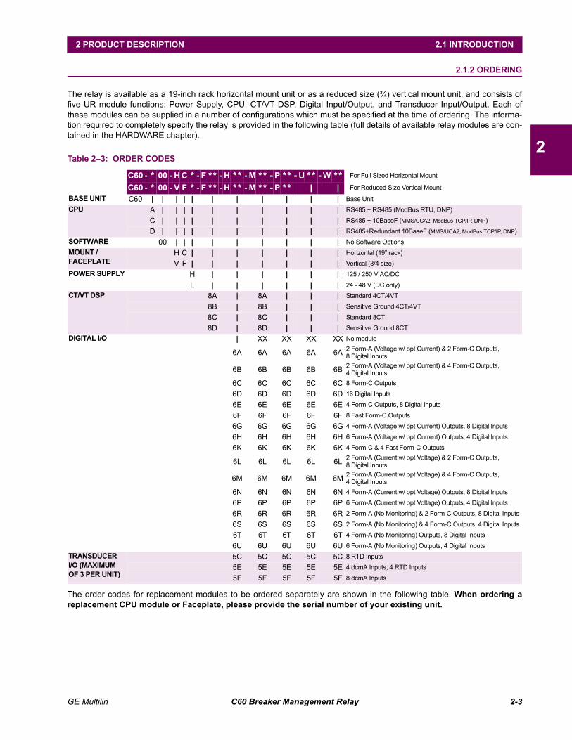
2.1.2 ORDERING
The relay is available as a 19-inch rack horizontal mount unit or as a reduced size (¾) vertical mount unit, and consists offive UR module functions: Power Supply, CPU, CT/VT DSP, Digital Input/Output, and Transducer Input/Output. Each ofthese modules can be supplied in a number of configurations which must be specified at the time of ordering. The informa-tion required to completely specify the relay is provided in the following table (full details of available relay modules are con-tained in the HARDWARE chapter).
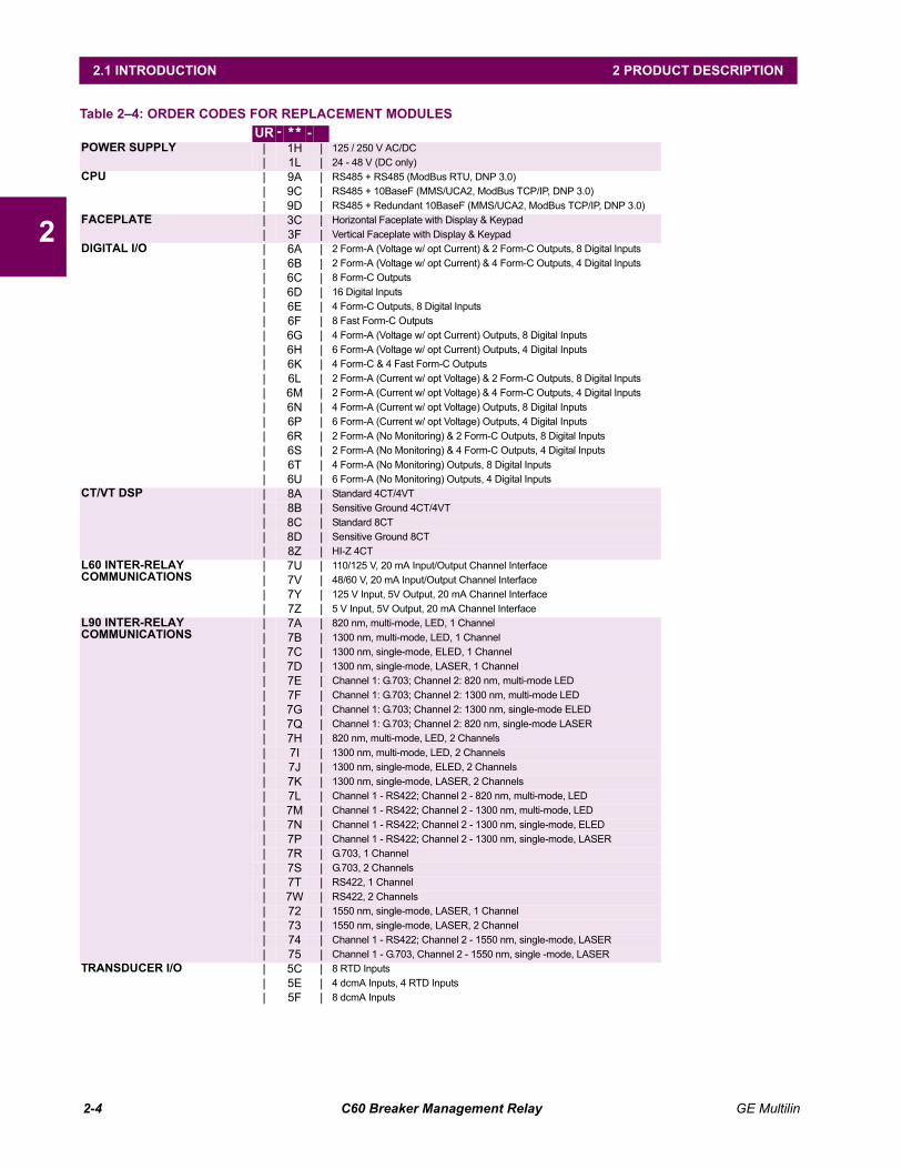
The order codes for replacement modules to be ordered separately are shown in the following table. When ordering areplacement CPU module or Faceplate, please provide the serial number of your existing unit.
Table 23: ORDER CODES
C60 - * 00 - H C * - F ** - H ** - M ** -P ** -U ** -W ** For Full Sized Horizontal Mount
C60 - * 00 - V F * - F ** - H ** - M ** -P ** | | For Reduced Size Vertical Mount
BASE UNIT C60 | | | | | | | | | | | Base UnitCPU A | | | | | | | | | | RS485 + RS485 (ModBus RTU, DNP)
C | | | | | | | | | | RS485 + 10BaseF (MMS/UCA2, ModBus TCP/IP, DNP)
D | | | | | | | | | | RS485+Redundant 10BaseF (MMS/UCA2, ModBus TCP/IP, DNP)SOFTWARE 00 | | | | | | | | | No Software OptionsMOUNT / FACEPLATE
H C | | | | | | | Horizontal (19 rack)
V F | | | | | | | Vertical (3/4 size)POWER SUPPLY H | | | | | | 125 / 250 V AC/DC
L | | | | | | 24 - 48 V (DC only)CT/VT DSP 8A | 8A | | | Standard 4CT/4VT
8B | 8B | | | Sensitive Ground 4CT/4VT
8C | 8C | | | Standard 8CT
8D | 8D | | | Sensitive Ground 8CTDIGITAL I/O | XX XX XX XX No module
6A 6A 6A 6A 6A 2 Form-A (Voltage w/ opt Current) & 2 Form-C Outputs, 8 Digital Inputs
6B 6B 6B 6B 6B 2 Form-A (Voltage w/ opt Current) & 4 Form-C Outputs, 4 Digital Inputs
6C 6C 6C 6C 6C 8 Form-C Outputs
6D 6D 6D 6D 6D 16 Digital Inputs
6E 6E 6E 6E 6E 4 Form-C Outputs, 8 Digital Inputs
6F 6F 6F 6F 6F 8 Fast Form-C Outputs
6G 6G 6G 6G 6G 4 Form-A (Voltage w/ opt Current) Outputs, 8 Digital Inputs
6H 6H 6H 6H 6H 6 Form-A (Voltage w/ opt Current) Outputs, 4 Digital Inputs
6K 6K 6K 6K 6K 4 Form-C & 4 Fast Form-C Outputs
6L 6L 6L 6L 6L 2 Form-A (Current w/ opt Voltage) & 2 Form-C Outputs,8 Digital Inputs
6M 6M 6M 6M 6M 2 Form-A (Current w/ opt Voltage) & 4 Form-C Outputs,4 Digital Inputs
6N 6N 6N 6N 6N 4 Form-A (Current w/ opt Voltage) Outputs, 8 Digital Inputs
6P 6P 6P 6P 6P 6 Form-A (Current w/ opt Voltage) Outputs, 4 Digital Inputs
6R 6R 6R 6R 6R 2 Form-A (No Monitoring) & 2 Form-C Outputs, 8 Digital Inputs
6S 6S 6S 6S 6S 2 Form-A (No Monitoring) & 4 Form-C Outputs, 4 Digital Inputs
6T 6T 6T 6T 6T 4 Form-A (No Monitoring) Outputs, 8 Digital Inputs
6U 6U 6U 6U 6U 6 Form-A (No Monitoring) Outputs, 4 Digital InputsTRANSDUCERI/O (MAXIMUM OF 3 PER UNIT)
5C 5C 5C 5C 5C 8 RTD Inputs
5E 5E 5E 5E 5E 4 dcmA Inputs, 4 RTD Inputs
5F 5F 5F 5F 5F 8 dcmA Inputs
2-4 C60 Breaker Management Relay GE Multilin
2.1 INTRODUCTION 2 PRODUCT DESCRIPTION
2
Table 24: ORDER CODES FOR REPLACEMENT MODULES UR - ** -
POWER SUPPLY | 1H | 125 / 250 V AC/DC| 1L | 24 - 48 V (DC only)
CPU | 9A | RS485 + RS485 (ModBus RTU, DNP 3.0)| 9C | RS485 + 10BaseF (MMS/UCA2, ModBus TCP/IP, DNP 3.0)| 9D | RS485 + Redundant 10BaseF (MMS/UCA2, ModBus TCP/IP, DNP 3.0)
FACEPLATE | 3C | Horizontal Faceplate with Display & Keypad| 3F | Vertical Faceplate with Display & Keypad
DIGITAL I/O | 6A | 2 Form-A (Voltage w/ opt Current) & 2 Form-C Outputs, 8 Digital Inputs| 6B | 2 Form-A (Voltage w/ opt Current) & 4 Form-C Outputs, 4 Digital Inputs| 6C | 8 Form-C Outputs| 6D | 16 Digital Inputs| 6E | 4 Form-C Outputs, 8 Digital Inputs| 6F | 8 Fast Form-C Outputs| 6G | 4 Form-A (Voltage w/ opt Current) Outputs, 8 Digital Inputs| 6H | 6 Form-A (Voltage w/ opt Current) Outputs, 4 Digital Inputs| 6K | 4 Form-C & 4 Fast Form-C Outputs| 6L | 2 Form-A (Current w/ opt Voltage) & 2 Form-C Outputs, 8 Digital Inputs| 6M | 2 Form-A (Current w/ opt Voltage) & 4 Form-C Outputs, 4 Digital Inputs| 6N | 4 Form-A (Current w/ opt Voltage) Outputs, 8 Digital Inputs| 6P | 6 Form-A (Current w/ opt Voltage) Outputs, 4 Digital Inputs| 6R | 2 Form-A (No Monitoring) & 2 Form-C Outputs, 8 Digital Inputs| 6S | 2 Form-A (No Monitoring) & 4 Form-C Outputs, 4 Digital Inputs| 6T | 4 Form-A (No Monitoring) Outputs, 8 Digital Inputs| 6U | 6 Form-A (No Monitoring) Outputs, 4 Digital Inputs
CT/VT DSP | 8A | Standard 4CT/4VT| 8B | Sensitive Ground 4CT/4VT| 8C | Standard 8CT| 8D | Sensitive Ground 8CT| 8Z | HI-Z 4CT
L60 INTER-RELAY COMMUNICATIONS
| 7U | 110/125 V, 20 mA Input/Output Channel Interface| 7V | 48/60 V, 20 mA Input/Output Channel Interface| 7Y | 125 V Input, 5V Output, 20 mA Channel Interface| 7Z | 5 V Input, 5V Output, 20 mA Channel Interface
L90 INTER-RELAY COMMUNICATIONS
| 7A | 820 nm, multi-mode, LED, 1 Channel| 7B | 1300 nm, multi-mode, LED, 1 Channel| 7C | 1300 nm, single-mode, ELED, 1 Channel| 7D | 1300 nm, single-mode, LASER, 1 Channel| 7E | Channel 1: G.703; Channel 2: 820 nm, multi-mode LED| 7F | Channel 1: G.703; Channel 2: 1300 nm, multi-mode LED| 7G | Channel 1: G.703; Channel 2: 1300 nm, single-mode ELED| 7Q | Channel 1: G.703; Channel 2: 820 nm, single-mode LASER| 7H | 820 nm, multi-mode, LED, 2 Channels| 7I | 1300 nm, multi-mode, LED, 2 Channels| 7J | 1300 nm, single-mode, ELED, 2 Channels| 7K | 1300 nm, single-mode, LASER, 2 Channels| 7L | Channel 1 - RS422; Channel 2 - 820 nm, multi-mode, LED| 7M | Channel 1 - RS422; Channel 2 - 1300 nm, multi-mode, LED| 7N | Channel 1 - RS422; Channel 2 - 1300 nm, single-mode, ELED| 7P | Channel 1 - RS422; Channel 2 - 1300 nm, single-mode, LASER| 7R | G.703, 1 Channel| 7S | G.703, 2 Channels| 7T | RS422, 1 Channel| 7W | RS422, 2 Channels| 72 | 1550 nm, single-mode, LASER, 1 Channel| 73 | 1550 nm, single-mode, LASER, 2 Channel| 74 | Channel 1 - RS422; Channel 2 - 1550 nm, single-mode, LASER| 75 | Channel 1 - G.703, Channel 2 - 1550 nm, single -mode, LASER
TRANSDUCER I/O | 5C | 8 RTD Inputs| 5E | 4 dcmA Inputs, 4 RTD Inputs| 5F | 8 dcmA Inputs
GE Multilin C60 Breaker Management Relay 2-5
2 PRODUCT DESCRIPTION 2.2 SPECIFICATIONS
2
2.2 SPECIFICATIONSSPECIFICATIONS ARE SUBJECT TO CHANGE WITHOUT NOTICE
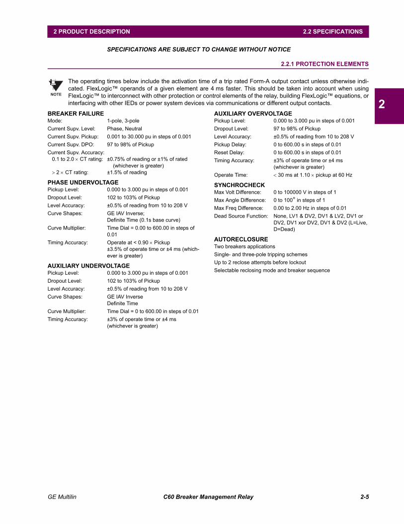
2.2.1 PROTECTION ELEMENTS
The operating times below include the activation time of a trip rated Form-A output contact unless otherwise indi-cated. FlexLogic operands of a given element are 4 ms faster. This should be taken into account when usingFlexLogic to interconnect with other protection or control elements of the relay, building FlexLogic equations, orinterfacing with other IEDs or power system devices via communications or different output contacts.
BREAKER FAILUREMode: 1-pole, 3-poleCurrent Supv. Level: Phase, NeutralCurrent Supv. Pickup: 0.001 to 30.000 pu in steps of 0.001Current Supv. DPO: 97 to 98% of PickupCurrent Supv. Accuracy:
0.1 to 2.0 × CT rating: ±0.75% of reading or ±1% of rated(whichever is greater)
> 2 × CT rating: ±1.5% of reading
PHASE UNDERVOLTAGEPickup Level: 0.000 to 3.000 pu in steps of 0.001Dropout Level: 102 to 103% of PickupLevel Accuracy: ±0.5% of reading from 10 to 208 VCurve Shapes: GE IAV Inverse;
Definite Time (0.1s base curve)Curve Multiplier: Time Dial = 0.00 to 600.00 in steps of
0.01Timing Accuracy: Operate at < 0.90 × Pickup
±3.5% of operate time or ±4 ms (which-ever is greater)
AUXILIARY UNDERVOLTAGEPickup Level: 0.000 to 3.000 pu in steps of 0.001Dropout Level: 102 to 103% of PickupLevel Accuracy: ±0.5% of reading from 10 to 208 VCurve Shapes: GE IAV Inverse
Definite TimeCurve Multiplier: Time Dial = 0 to 600.00 in steps of 0.01Timing Accuracy: ±3% of operate time or ±4 ms
(whichever is greater)
AUXILIARY OVERVOLTAGEPickup Level: 0.000 to 3.000 pu in steps of 0.001Dropout Level: 97 to 98% of PickupLevel Accuracy: ±0.5% of reading from 10 to 208 VPickup Delay: 0 to 600.00 s in steps of 0.01Reset Delay: 0 to 600.00 s in steps of 0.01Timing Accuracy: ±3% of operate time or ±4 ms
(whichever is greater)Operate Time: < 30 ms at 1.10 × pickup at 60 Hz
SYNCHROCHECKMax Volt Difference: 0 to 100000 V in steps of 1Max Angle Difference: 0 to 100° in steps of 1Max Freq Difference: 0.00 to 2.00 Hz in steps of 0.01Dead Source Function: None, LV1 & DV2, DV1 & LV2, DV1 or
DV2, DV1 xor DV2, DV1 & DV2 (L=Live, D=Dead)
AUTORECLOSURETwo breakers applicationsSingle- and three-pole tripping schemesUp to 2 reclose attempts before lockoutSelectable reclosing mode and breaker sequence
NOTE
2-6 C60 Breaker Management Relay GE Multilin
2.2 SPECIFICATIONS 2 PRODUCT DESCRIPTION
2
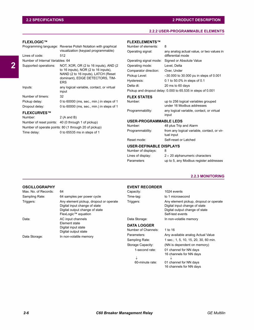
2.2.2 USER-PROGRAMMABLE ELEMENTS
FLEXLOGICProgramming language: Reverse Polish Notation with graphical
visualization (keypad programmable)Lines of code: 512Number of Internal Variables: 64Supported operations: NOT, XOR, OR (2 to 16 inputs), AND (2
to 16 inputs), NOR (2 to 16 inputs), NAND (2 to 16 inputs), LATCH (Reset dominant), EDGE DETECTORS, TIM-ERS
Inputs: any logical variable, contact, or virtual input
Number of timers: 32Pickup delay: 0 to 60000 (ms, sec., min.) in steps of 1Dropout delay: 0 to 60000 (ms, sec., min.) in steps of 1
FLEXCURVESNumber: 2 (A and B)Number of reset points: 40 (0 through 1 of pickup)Number of operate points: 80 (1 through 20 of pickup)Time delay: 0 to 65535 ms in steps of 1
FLEXELEMENTSNumber of elements: 8Operating signal: any analog actual value, or two values in
differential modeOperating signal mode: Signed or Absolute ValueOperating mode: Level, DeltaComparator direction: Over, UnderPickup Level: 30.000 to 30.000 pu in steps of 0.001Hysteresis: 0.1 to 50.0% in steps of 0.1Delta dt: 20 ms to 60 daysPickup and dropout delay: 0.000 to 65.535 in steps of 0.001
FLEX STATESNumber: up to 256 logical variables grouped
under 16 Modbus addressesProgrammability: any logical variable, contact, or virtual
input
USER-PROGRAMMABLE LEDSNumber: 48 plus Trip and AlarmProgrammability: from any logical variable, contact, or vir-
tual inputReset mode: Self-reset or Latched
USER-DEFINABLE DISPLAYSNumber of displays: 8Lines of display: 2 × 20 alphanumeric charactersParameters up to 5, any Modbus register addresses
2.2.3 MONITORING
OSCILLOGRAPHYMax. No. of Records: 64Sampling Rate: 64 samples per power cycleTriggers: Any element pickup, dropout or operate
Digital input change of stateDigital output change of stateFlexLogic equation
Data: AC input channelsElement stateDigital input stateDigital output state
Data Storage: In non-volatile memory
EVENT RECORDERCapacity: 1024 eventsTime-tag: to 1 microsecondTriggers: Any element pickup, dropout or operate
Digital input change of stateDigital output change of stateSelf-test events
Data Storage: In non-volatile memory
DATA LOGGERNumber of Channels: 1 to 16Parameters: Any available analog Actual ValueSampling Rate: 1 sec.; 1, 5, 10, 15, 20, 30, 60 min.Storage Capacity: (NN is dependent on memory)
1-second rate: 01 channel for NN days16 channels for NN days
↓ ↓60-minute rate: 01 channel for NN days
16 channels for NN days
GE Multilin C60 Breaker Management Relay 2-7
2 PRODUCT DESCRIPTION 2.2 SPECIFICATIONS
2
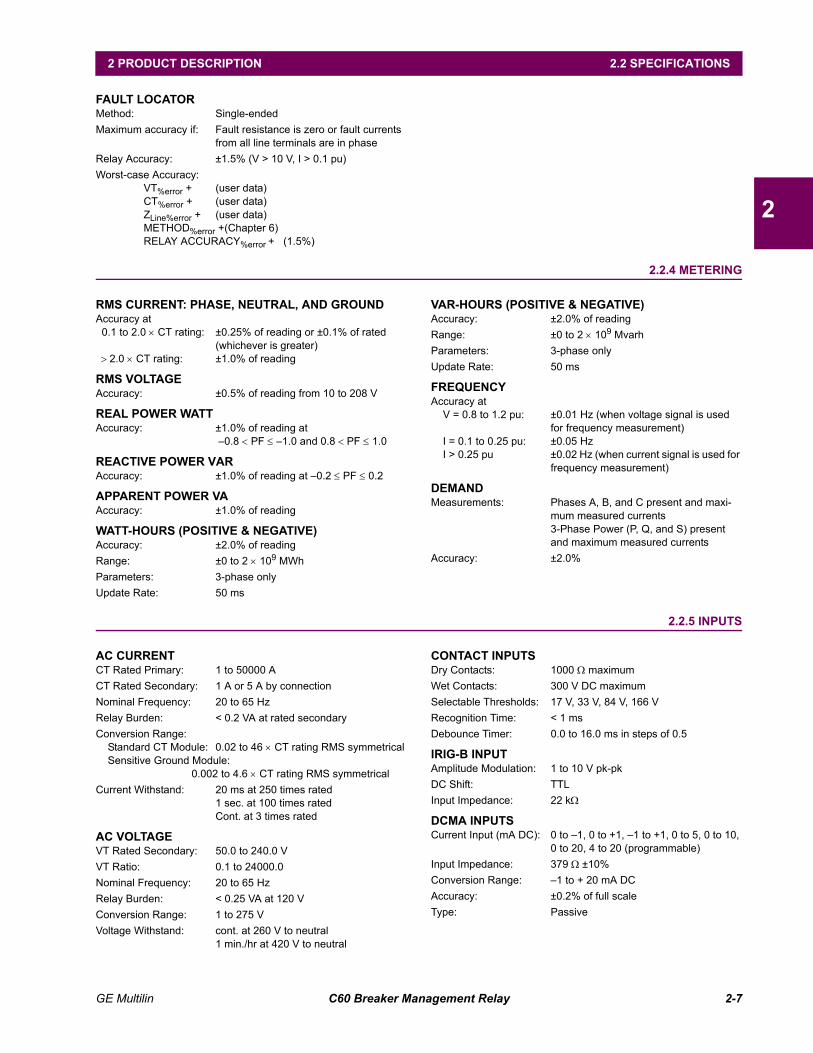
FAULT LOCATORMethod: Single-endedMaximum accuracy if: Fault resistance is zero or fault currents
from all line terminals are in phaseRelay Accuracy: ±1.5% (V > 10 V, I > 0.1 pu)Worst-case Accuracy:
VT%error + (user data)CT%error + (user data)ZLine%error + (user data)METHOD%error +(Chapter 6)RELAY ACCURACY%error + (1.5%)
2.2.4 METERING
RMS CURRENT: PHASE, NEUTRAL, AND GROUNDAccuracy at
0.1 to 2.0 × CT rating: ±0.25% of reading or ±0.1% of rated(whichever is greater)
> 2.0 × CT rating: ±1.0% of reading
RMS VOLTAGEAccuracy: ±0.5% of reading from 10 to 208 V
REAL POWER WATTAccuracy: ±1.0% of reading at
0.8 < PF ≤ 1.0 and 0.8 < PF ≤ 1.0
REACTIVE POWER VARAccuracy: ±1.0% of reading at 0.2 ≤ PF ≤ 0.2
APPARENT POWER VAAccuracy: ±1.0% of reading
WATT-HOURS (POSITIVE & NEGATIVE)Accuracy: ±2.0% of readingRange: ±0 to 2 × 10⁹ MWhParameters: 3-phase onlyUpdate Rate: 50 ms
VAR-HOURS (POSITIVE & NEGATIVE)Accuracy: ±2.0% of readingRange: ±0 to 2 × 10⁹ MvarhParameters: 3-phase onlyUpdate Rate: 50 ms
FREQUENCYAccuracy at
V = 0.8 to 1.2 pu: ±0.01 Hz (when voltage signal is used for frequency measurement)
I = 0.1 to 0.25 pu: ±0.05 HzI > 0.25 pu ±0.02 Hz (when current signal is used for
frequency measurement)
DEMANDMeasurements: Phases A, B, and C present and maxi-
mum measured currents3-Phase Power (P, Q, and S) present and maximum measured currents
Accuracy: ±2.0%
2.2.5 INPUTS
AC CURRENTCT Rated Primary: 1 to 50000 ACT Rated Secondary: 1 A or 5 A by connectionNominal Frequency: 20 to 65 HzRelay Burden: < 0.2 VA at rated secondaryConversion Range:
Standard CT Module: 0.02 to 46 × CT rating RMS symmetricalSensitive Ground Module:
0.002 to 4.6 × CT rating RMS symmetricalCurrent Withstand: 20 ms at 250 times rated
1 sec. at 100 times ratedCont. at 3 times rated
AC VOLTAGEVT Rated Secondary: 50.0 to 240.0 VVT Ratio: 0.1 to 24000.0Nominal Frequency: 20 to 65 HzRelay Burden: < 0.25 VA at 120 VConversion Range: 1 to 275 VVoltage Withstand: cont. at 260 V to neutral
1 min./hr at 420 V to neutral
CONTACT INPUTSDry Contacts: 1000 Ω maximumWet Contacts: 300 V DC maximumSelectable Thresholds: 17 V, 33 V, 84 V, 166 VRecognition Time: < 1 msDebounce Timer: 0.0 to 16.0 ms in steps of 0.5
IRIG-B INPUTAmplitude Modulation: 1 to 10 V pk-pkDC Shift: TTLInput Impedance: 22 kΩ
DCMA INPUTSCurrent Input (mA DC): 0 to 1, 0 to +1, 1 to +1, 0 to 5, 0 to 10,
0 to 20, 4 to 20 (programmable)Input Impedance: 379 Ω ±10%Conversion Range: 1 to + 20 mA DCAccuracy: ±0.2% of full scaleType: Passive

2-8 C60 Breaker Management Relay GE Multilin
2.2 SPECIFICATIONS 2 PRODUCT DESCRIPTION
2
RTD INPUTSTypes (3-wire): 100 Ω Platinum, 100 & 120 Ω Nickel, 10
Ω CopperSensing Current: 5 mARange: 50 to +250°CAccuracy: ±2°CIsolation: 36 V pk-pk
GE Multilin C60 Breaker Management Relay 2-9
2 PRODUCT DESCRIPTION 2.2 SPECIFICATIONS
2
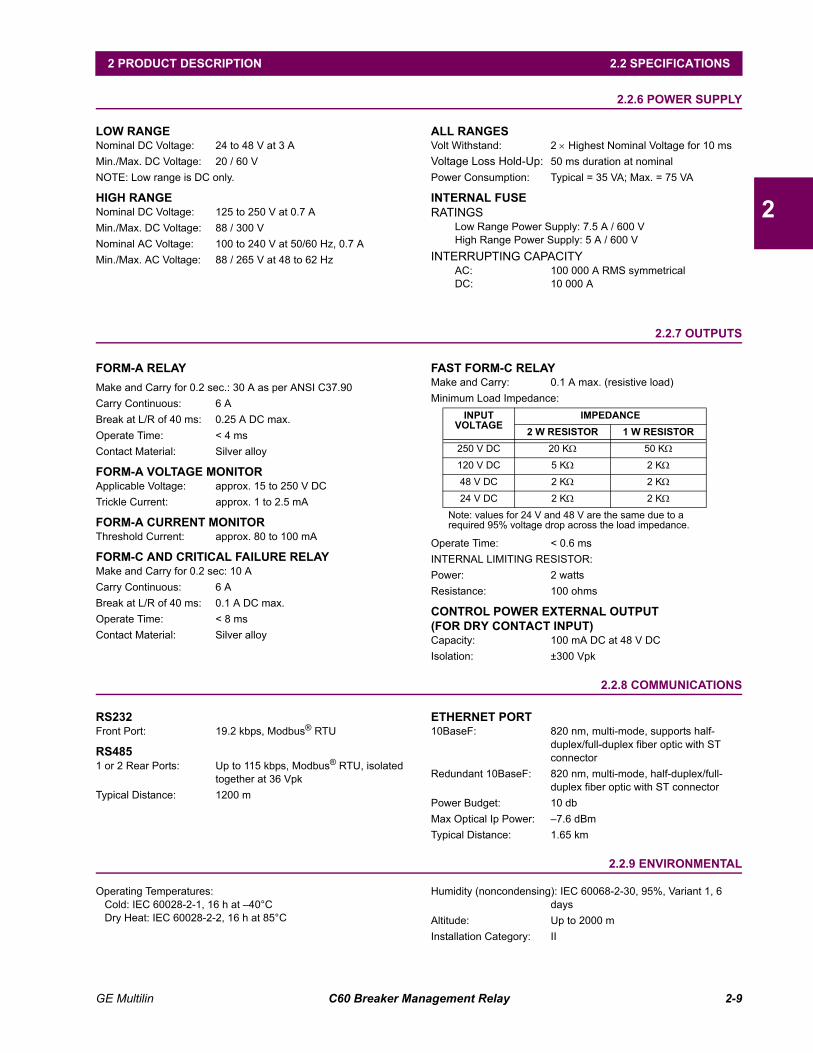
2.2.6 POWER SUPPLY
LOW RANGENominal DC Voltage: 24 to 48 V at 3 AMin./Max. DC Voltage: 20 / 60 VNOTE: Low range is DC only.
HIGH RANGENominal DC Voltage: 125 to 250 V at 0.7 AMin./Max. DC Voltage: 88 / 300 VNominal AC Voltage: 100 to 240 V at 50/60 Hz, 0.7 AMin./Max. AC Voltage: 88 / 265 V at 48 to 62 Hz
ALL RANGESVolt Withstand: 2 × Highest Nominal Voltage for 10 msVoltage Loss Hold-Up: 50 ms duration at nominalPower Consumption: Typical = 35 VA; Max. = 75 VA
INTERNAL FUSERATINGS
Low Range Power Supply: 7.5 A / 600 VHigh Range Power Supply: 5 A / 600 V
INTERRUPTING CAPACITYAC: 100 000 A RMS symmetricalDC: 10 000 A
2.2.7 OUTPUTS
FORM-A RELAYMake and Carry for 0.2 sec.: 30 A as per ANSI C37.90Carry Continuous: 6 ABreak at L/R of 40 ms: 0.25 A DC max.Operate Time: < 4 msContact Material: Silver alloy
FORM-A VOLTAGE MONITORApplicable Voltage: approx. 15 to 250 V DCTrickle Current: approx. 1 to 2.5 mA
FORM-A CURRENT MONITORThreshold Current: approx. 80 to 100 mA
FORM-C AND CRITICAL FAILURE RELAYMake and Carry for 0.2 sec: 10 ACarry Continuous: 6 ABreak at L/R of 40 ms: 0.1 A DC max.Operate Time: < 8 msContact Material: Silver alloy
FAST FORM-C RELAYMake and Carry: 0.1 A max. (resistive load)Minimum Load Impedance:
Operate Time: < 0.6 msINTERNAL LIMITING RESISTOR:Power: 2 wattsResistance: 100 ohms
CONTROL POWER EXTERNAL OUTPUT(FOR DRY CONTACT INPUT)Capacity: 100 mA DC at 48 V DCIsolation: ±300 Vpk
2.2.8 COMMUNICATIONS
RS232Front Port: 19.2 kbps, Modbus® RTU
RS4851 or 2 Rear Ports: Up to 115 kbps, Modbus® RTU, isolated
together at 36 VpkTypical Distance: 1200 m
ETHERNET PORT10BaseF: 820 nm, multi-mode, supports half-
duplex/full-duplex fiber optic with ST connector
Redundant 10BaseF: 820 nm, multi-mode, half-duplex/full-duplex fiber optic with ST connector
Power Budget: 10 dbMax Optical Ip Power: 7.6 dBmTypical Distance: 1.65 km
2.2.9 ENVIRONMENTAL
Operating Temperatures:Cold: IEC 60028-2-1, 16 h at 40°CDry Heat: IEC 60028-2-2, 16 h at 85°C
Humidity (noncondensing): IEC 60068-2-30, 95%, Variant 1, 6 days
Altitude: Up to 2000 mInstallation Category: II
INPUTVOLTAGE
IMPEDANCE2 W RESISTOR 1 W RESISTOR
250 V DC 20 KΩ 50 KΩ
120 V DC 5 KΩ 2 KΩ
48 V DC 2 KΩ 2 KΩ
24 V DC 2 KΩ 2 KΩ
Note: values for 24 V and 48 V are the same due to a required 95% voltage drop across the load impedance.

2-10 C60 Breaker Management Relay GE Multilin
2.2 SPECIFICATIONS 2 PRODUCT DESCRIPTION
2
2.2.10 TYPE TESTS
Electrical Fast Transient: ANSI/IEEE C37.90.1IEC 61000-4-4IEC 60255-22-4
Oscillatory Transient: ANSI/IEEE C37.90.1IEC 61000-4-12
Insulation Resistance: IEC 60255-5Dielectric Strength: IEC 60255-6
ANSI/IEEE C37.90Electrostatic Discharge: EN 61000-4-2Surge Immunity: EN 61000-4-5RFI Susceptibility: ANSI/IEEE C37.90.2
IEC 61000-4-3IEC 60255-22-3Ontario Hydro C-5047-77
Conducted RFI: IEC 61000-4-6Voltage Dips/Interruptions/Variations:
IEC 61000-4-11IEC 60255-11
Power Frequency Magnetic Field Immunity:IEC 61000-4-8
Vibration Test (sinusoidal): IEC 60255-21-1Shock and Bump: IEC 60255-21-2
Type test report available upon request.
2.2.11 PRODUCTION TESTS
THERMALProducts go through an environmental test based upon an Accepted Quality Level (AQL) sampling process.
2.2.12 APPROVALS
APPROVALSUL Listed for the USA and CanadaCE:
LVD 73/23/EEC: IEC 1010-1EMC 81/336/EEC: EN 50081-2
EN 50082-2
2.2.13 MAINTENANCE
Cleaning: Normally, cleaning is not required; but for situations where dust has accumulated on the faceplate display, a dry cloth can be used.
NOTE
GE Multilin C60 Breaker Management Relay 3-1
3 HARDWARE 3.1 DESCRIPTION
3
3 HARDWARE 3.1 DESCRIPTION 3.1.1 PANEL CUTOUT
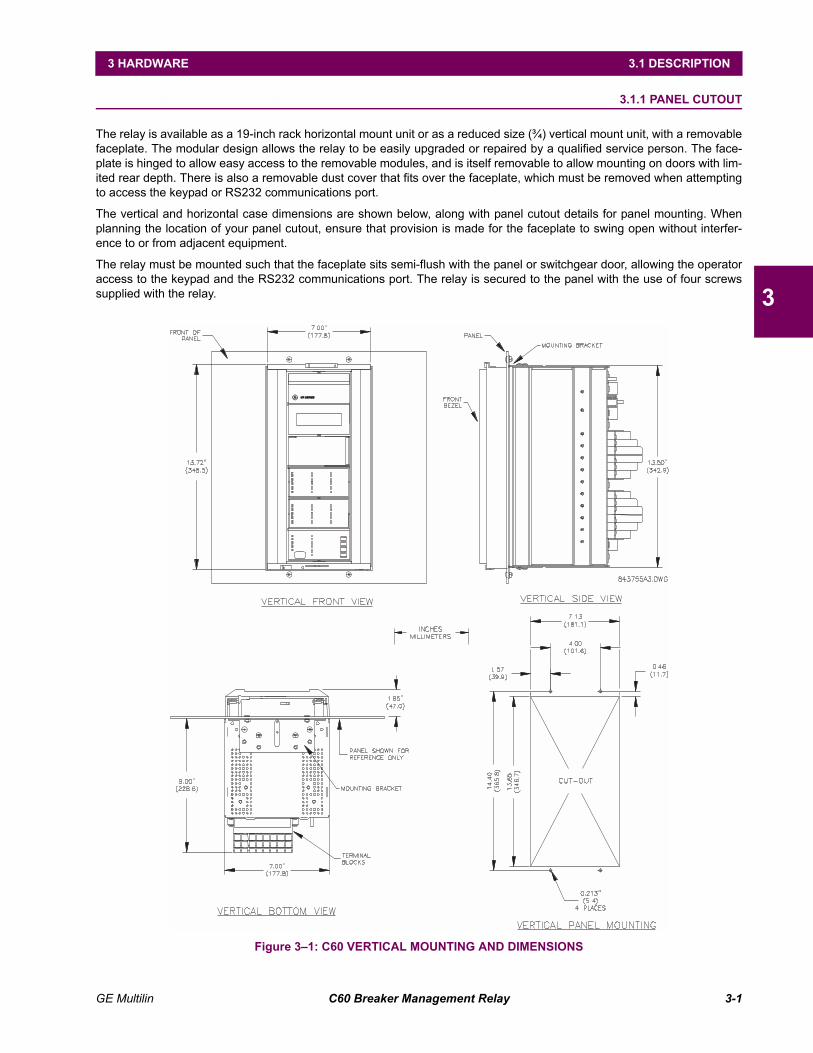
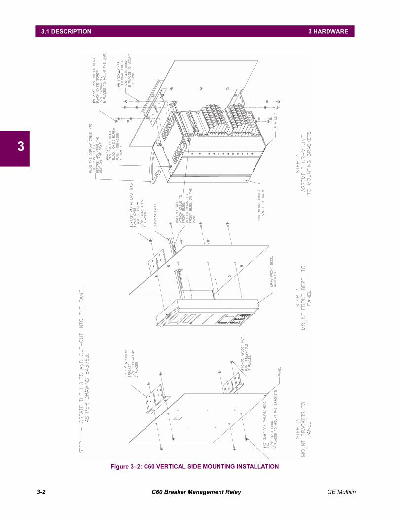
The relay is available as a 19-inch rack horizontal mount unit or as a reduced size (¾) vertical mount unit, with a removablefaceplate. The modular design allows the relay to be easily upgraded or repaired by a qualified service person. The face-plate is hinged to allow easy access to the removable modules, and is itself removable to allow mounting on doors with lim-ited rear depth. There is also a removable dust cover that fits over the faceplate, which must be removed when attemptingto access the keypad or RS232 communications port.
The vertical and horizontal case dimensions are shown below, along with panel cutout details for panel mounting. Whenplanning the location of your panel cutout, ensure that provision is made for the faceplate to swing open without interfer-ence to or from adjacent equipment.
The relay must be mounted such that the faceplate sits semi-flush with the panel or switchgear door, allowing the operatoraccess to the keypad and the RS232 communications port. The relay is secured to the panel with the use of four screwssupplied with the relay.
Figure 31: C60 VERTICAL MOUNTING AND DIMENSIONS
e UR SERIESUR SERIES
3-2 C60 Breaker Management Relay GE Multilin
3.1 DESCRIPTION 3 HARDWARE
3
Figure 32: C60 VERTICAL SIDE MOUNTING INSTALLATION
GE Multilin C60 Breaker Management Relay 3-3
3 HARDWARE 3.1 DESCRIPTION
3
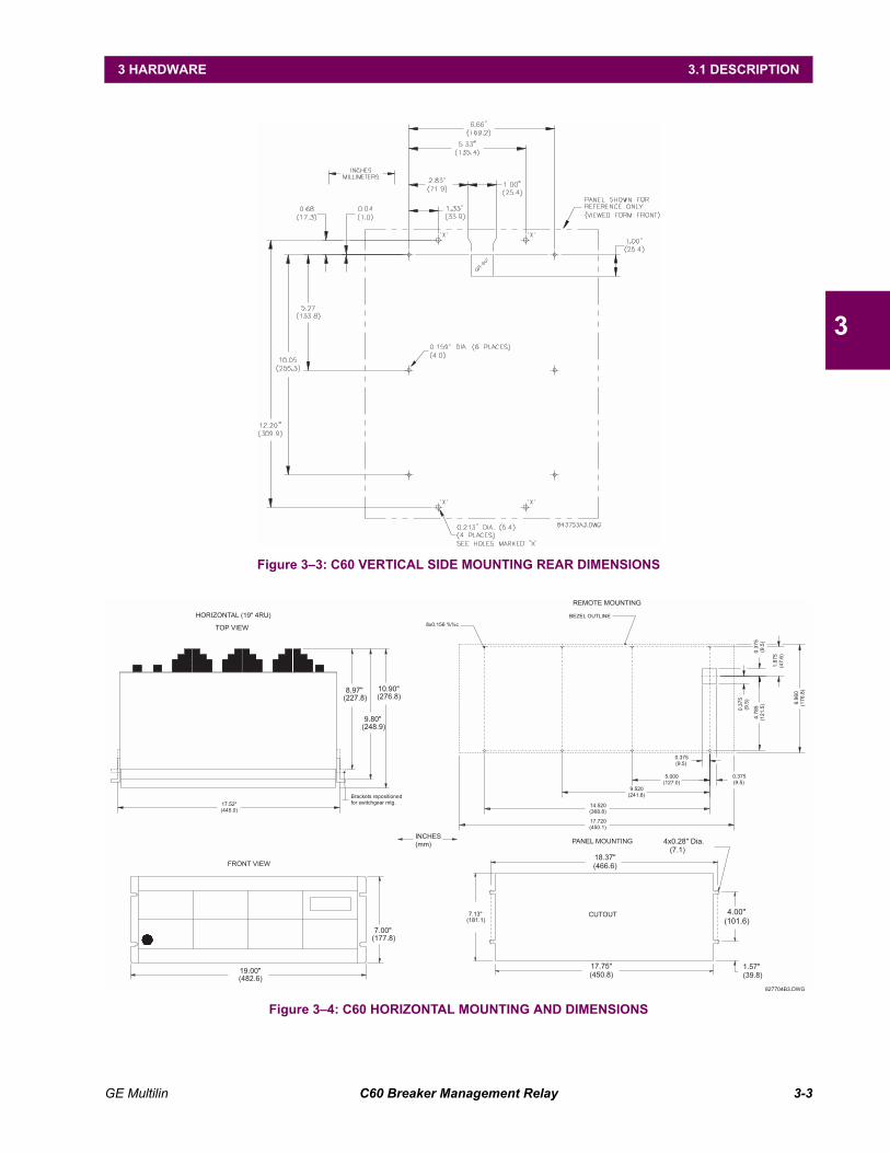
Figure 33: C60 VERTICAL SIDE MOUNTING REAR DIMENSIONS
Figure 34: C60 HORIZONTAL MOUNTING AND DIMENSIONS
INCHES
(mm)
REMOTE MOUNTING
BEZEL OUTLINE
8x0.156 %%c
0.375
(9.5)
5.000
(127.0)
9.520
(241.8)
14.520
(368.8)
0.375
(9.5)
17.720
(450.1)
0.3
75
(9.5
)
4.7
85
(12
1.5
)
0.3
75
(9.5
)
1.8
75
(47
.6)
6.9
60
(17
6.8
)10.90"
(276.8)
TOP VIEW
9.80"
(248.9)
HORIZONTAL (19" 4RU)
8.97"
(227.8)
Brackets repositioned
for switchgear mtg.17.52"
(445.0)
827704B3.DWG
7.13"
(181.1)CUTOUT
17.75"
(450.8)
PANEL MOUNTING
18.37"
(466.6)
1.57"
(39.8)
4.00"
(101.6)
4x0.28" Dia.
(7.1)
19.00"
(482.6)
7.00"
(177.8)
FRONT VIEW
3-4 C60 Breaker Management Relay GE Multilin
3.1 DESCRIPTION 3 HARDWARE
3
3.1.2 MODULE WITHDRAWAL/INSERTION
Module withdrawal and insertion may only be performed when control power has been removed from theunit. Inserting an incorrect module type into a slot may result in personal injury, damage to the unit or con-nected equipment, or undesired operation!
Proper electrostatic discharge protection (i.e. a static strap) must be used when coming in contact withmodules while the relay is energized!
The relay, being modular in design, allows for the withdrawal and insertion of modules. Modules must only be replaced withlike modules in their original factory configured slots.
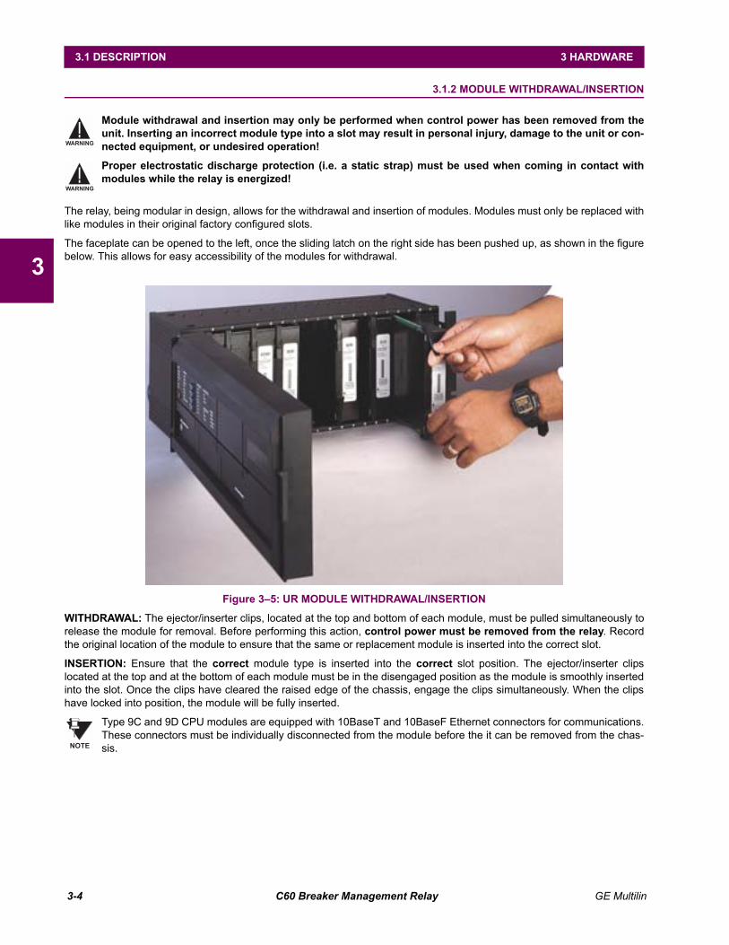
The faceplate can be opened to the left, once the sliding latch on the right side has been pushed up, as shown in the figurebelow. This allows for easy accessibility of the modules for withdrawal.
Figure 35: UR MODULE WITHDRAWAL/INSERTION
WITHDRAWAL: The ejector/inserter clips, located at the top and bottom of each module, must be pulled simultaneously torelease the module for removal. Before performing this action, control power must be removed from the relay. Recordthe original location of the module to ensure that the same or replacement module is inserted into the correct slot.
INSERTION: Ensure that the correct module type is inserted into the correct slot position. The ejector/inserter clipslocated at the top and at the bottom of each module must be in the disengaged position as the module is smoothly insertedinto the slot. Once the clips have cleared the raised edge of the chassis, engage the clips simultaneously. When the clipshave locked into position, the module will be fully inserted.
Type 9C and 9D CPU modules are equipped with 10BaseT and 10BaseF Ethernet connectors for communications.These connectors must be individually disconnected from the module before the it can be removed from the chas-sis.
WARNING
WARNING
NOTE
GE Multilin C60 Breaker Management Relay 3-5
3 HARDWARE 3.1 DESCRIPTION
3
3.1.3 REAR TERMINAL LAYOUT
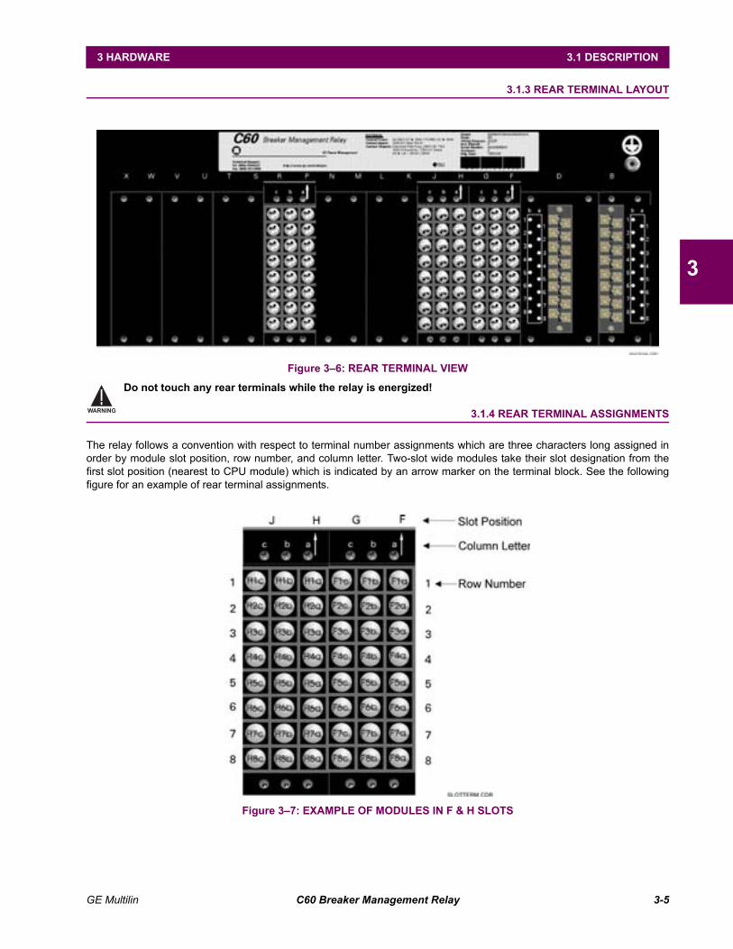
Figure 36: REAR TERMINAL VIEW
Do not touch any rear terminals while the relay is energized!
3.1.4 REAR TERMINAL ASSIGNMENTS
The relay follows a convention with respect to terminal number assignments which are three characters long assigned inorder by module slot position, row number, and column letter. Two-slot wide modules take their slot designation from thefirst slot position (nearest to CPU module) which is indicated by an arrow marker on the terminal block. See the followingfigure for an example of rear terminal assignments.
Figure 37: EXAMPLE OF MODULES IN F & H SLOTS
WARNING
3-6 C60 Breaker Management Relay GE Multilin
3.2 WIRING 3 HARDWARE
3
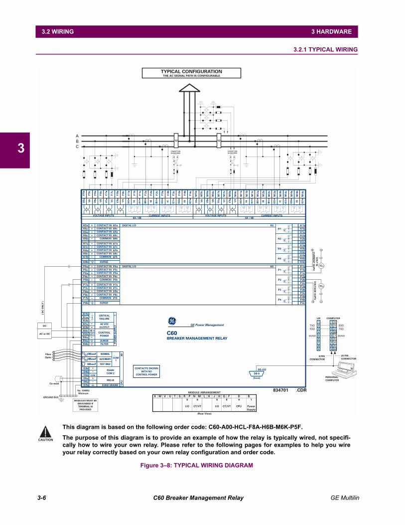
3.2 WIRING 3.2.1 TYPICAL WIRING
Figure 38: TYPICAL WIRING DIAGRAM
C60BREAKER MANAGEMENT RELAY
(Rear View)
1
PowerSupply
9
CPU
8
CT/VT
6
I/O
6
I/O
8
CT/VT
MODULE ARRANGEMENTJU MX LW KV BHT DN GS P FR
GE Power Management
ABC
CONNECTIONAS REQUIRED
CONNECTIONAS REQUIRED
52 52
834701 .CDRCo-axial
AC or DC
DC
( DC
ON
LY )
GROUND BUS
No. 10AWGMinimum
MODULES MUST BEGROUNDED IFTERMINAL IS
PROVIDED
TYPICAL CONFIGURATIONTHE AC SIGNAL PATH IS CONFIGURABLE
RS-232
DB-9
(front)
UR COMPUTER1
TXD RXDRXD TXD
SGND SGND
1 832
20764522
25 PINCONNECTOR
PERSONALCOMPUTER
9 PINCONNECTOR
2 23 34 45 56 67 78 89 9
TC
TC
2
1
VO
LTAG
E SU
PV.V
OLT &
CU
RR
ENT S
UPV.
CONTACTS SHOWNWITH NO
CONTROL POWER
1c 4a
MMMMMMMMMMMMMMMMMMMM
8c8a 3c5a 5c 7c
CURRENT INPUTS
6a 7a6c 2c
VX
VA
VB
VC
4c1a 4b1b 2a 3a2b 3b
VOLTAGE INPUTS8A / 8B
VX
VA
VB
VC IA IB IC IGIA5
IA1
IB5
IC5
IG5
IB1
IC1
IG1
1a
2b
1c1b
2c
2a
4a
4c
3b3a
4b
3c
CONTACT IN 5a
CONTACT IN 7a
CONTACT IN 5c
CONTACT IN 7c
CONTACT IN 6a
CONTACT IN 8a
CONTACT IN 6c
CONTACT IN 8c
COMMON 5b
COMMON 7b
SURGE
6a
8a
5b
7b
8b
5aHHHHH
HHHHH
H
HHHHH
HHHHH
HHH
H
H
H
HHHHHHHHHH
7a
6c
8c
5c
7c
1
2
3
4
I
V
I
V
I
V
I
V
DIGITAL I/O 6G
1a
2b
1c1b
2c
2a
4a
4c
3b3a
4b
3c
CONTACT IN 5a
CONTACT IN 7a
CONTACT IN 5c
CONTACT IN 7c
CONTACT IN 6a
CONTACT IN 8a
CONTACT IN 6c
CONTACT IN 8c
COMMON 5b
COMMON 7b
SURGE
6a
8a
5b
7b
8b
5aPPPPP
PPPPP
P
PPPPP
PPPPP
PPP
P
P
P
PPPPPPPPPP
7a
6c
8c
5c
7c
1
2
3
4
I
V
I
V
I
V
I
V
DIGITAL I/O 6G
Tx1
Tx2
Rx1
Rx2
SURGE GROUNDD7bD6a
D4bD5b
D3b
10BaseT
10BaseF
10BaseF
D5aCOM
CPU
9D
COM1
TEST ONLY
ALTERNATE
NORMAL
RS485COM 2
IRIG-B
CRITICALFAILURE
48 VDCOUTPUT
CONTROLPOWER
HILO
POW
ER S
UPP
LY1
FILTERSURGE
3a
1b
8a
6b
8b
6a
BBBBBBBBBB
3b
1a2b
5b
1c 4a
FFFFFFFFFFFFFFFFFFFF
8c8a 3c5a 5c 7c
CURRENT INPUTS
6a 7a6c 2c
VX
VA
VB
VC
4c1a 4b1b 2a 3a2b 3b
VOLTAGE INPUTS8A / 8B
VX
VA
VB
VC IA IB IC IGIA5
IA1
IB5
IC5
IG5
IB1
IC1
IG1
FibreOptic
This diagram is based on the following order code: C60-A00-HCL-F8A-H6B-M6K-P5F.
The purpose of this diagram is to provide an example of how the relay is typically wired, not specifi-cally how to wire your own relay. Please refer to the following pages for examples to help you wireyour relay correctly based on your own relay configuration and order code.
CAUTION
GE Multilin C60 Breaker Management Relay 3-7
3 HARDWARE 3.2 WIRING
3
3.2.2 DIELECTRIC STRENGTH RATINGS AND TESTING
a) RATINGS
The dielectric strength of UR module hardware is shown in the following table:
b) TESTING
Filter networks and transient protection clamps are used in module hardware to prevent damage caused by high peak volt-age transients, radio frequency interference (RFI) and electromagnetic interference (EMI). These protective componentscan be damaged by application of the ANSI/IEEE C37.90 specified test voltage for a period longer than the specified oneminute. For testing of dielectric strength where the test interval may exceed one minute, always observe the following pre-cautions:
Test Precautions:
1. The connection from ground to the Filter Ground (Terminal 8b) and Surge Ground (Terminal 8a) must be removedbefore testing.
2. Some versions of the digital I/O module have a Surge Ground connection on Terminal 8b. On these module types, thisconnection must be removed before testing.
3.2.3 CONTROL POWER
CONTROL POWER SUPPLIED TO THE RELAY MUST BE CONNECTED TO THE MATCHING POWER SUPPLYRANGE OF THE RELAY. IF THE VOLTAGE IS APPLIED TO THE WRONG TERMINALS, DAMAGE MAYOCCUR!
The power supply module can be ordered with either of two possible voltage ranges. Each range has a dedicated inputconnection for proper operation. The ranges are as shown below (see the Technical Specifications section for details).
The power supply module provides power to the relay and supplies power for dry contact input connections.
Table 31: DIELECTRIC STRENGTH OF UR MODULE HARDWAREMODULE
TYPEMODULE FUNCTION TERMINALS DIELECTRIC STRENGTH
(AC)FROM TO1 Power Supply High (+); Low (+); () Chassis 2000 V AC for 1 min.
(See Precaution 1)1 Power Supply 48 V DC (+) and () Chassis 2000 V AC for 1 min.
(See Precaution 1)1 Power Supply Relay Terminals Chassis 2000 V AC for 1 min.
(See Precaution 1)2 Reserved for Future N/A N/A N/A3 Reserved for Future N/A N/A N/A4 Reserved for Future N/A N/A N/A5 Analog I/O All except 8b Chassis < 50 V DC6 Digital I/O All (See Precaution 2) Chassis 2000 V AC for 1 min.8 CT/VT All Chassis 2000 V AC for 1 min.9 CPU All except 7b Chassis < 50 VDC
Table 32: CONTROL POWER VOLTAGE RANGERANGE NOMINAL VOLTAGELO 24 to 48 V (DC only)HI 125 to 250 V
CAUTION
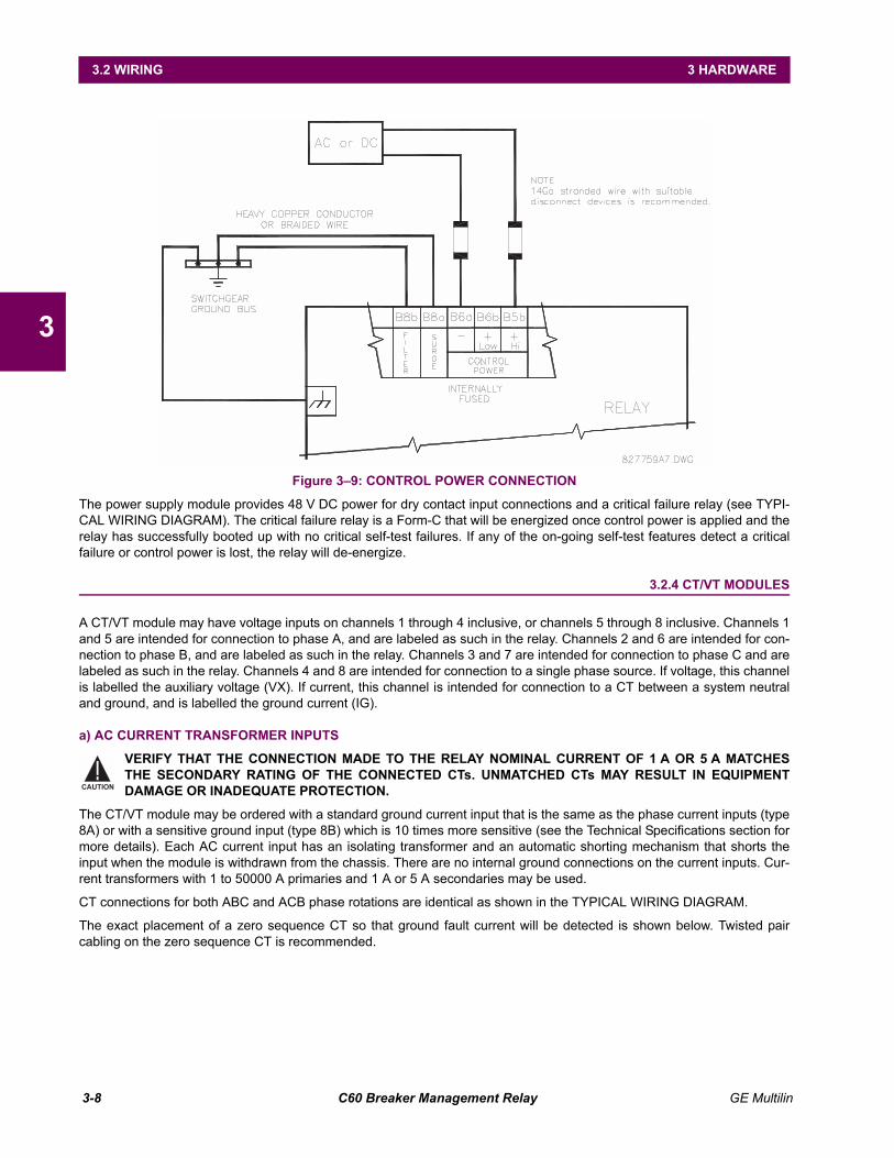
3-8 C60 Breaker Management Relay GE Multilin
3.2 WIRING 3 HARDWARE
3
Figure 39: CONTROL POWER CONNECTION
The power supply module provides 48 V DC power for dry contact input connections and a critical failure relay (see TYPI-CAL WIRING DIAGRAM). The critical failure relay is a Form-C that will be energized once control power is applied and therelay has successfully booted up with no critical self-test failures. If any of the on-going self-test features detect a criticalfailure or control power is lost, the relay will de-energize.
3.2.4 CT/VT MODULES
A CT/VT module may have voltage inputs on channels 1 through 4 inclusive, or channels 5 through 8 inclusive. Channels 1and 5 are intended for connection to phase A, and are labeled as such in the relay. Channels 2 and 6 are intended for con-nection to phase B, and are labeled as such in the relay. Channels 3 and 7 are intended for connection to phase C and arelabeled as such in the relay. Channels 4 and 8 are intended for connection to a single phase source. If voltage, this channelis labelled the auxiliary voltage (VX). If current, this channel is intended for connection to a CT between a system neutraland ground, and is labelled the ground current (IG).
a) AC CURRENT TRANSFORMER INPUTS
VERIFY THAT THE CONNECTION MADE TO THE RELAY NOMINAL CURRENT OF 1 A OR 5 A MATCHESTHE SECONDARY RATING OF THE CONNECTED CTs. UNMATCHED CTs MAY RESULT IN EQUIPMENTDAMAGE OR INADEQUATE PROTECTION.
The CT/VT module may be ordered with a standard ground current input that is the same as the phase current inputs (type8A) or with a sensitive ground input (type 8B) which is 10 times more sensitive (see the Technical Specifications section formore details). Each AC current input has an isolating transformer and an automatic shorting mechanism that shorts theinput when the module is withdrawn from the chassis. There are no internal ground connections on the current inputs. Cur-rent transformers with 1 to 50000 A primaries and 1 A or 5 A secondaries may be used.
CT connections for both ABC and ACB phase rotations are identical as shown in the TYPICAL WIRING DIAGRAM.
The exact placement of a zero sequence CT so that ground fault current will be detected is shown below. Twisted paircabling on the zero sequence CT is recommended.
CAUTION
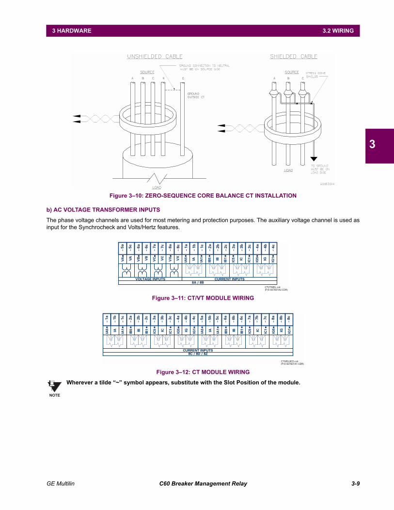
GE Multilin C60 Breaker Management Relay 3-9
3 HARDWARE 3.2 WIRING
3
Figure 310: ZERO-SEQUENCE CORE BALANCE CT INSTALLATION
b) AC VOLTAGE TRANSFORMER INPUTS
The phase voltage channels are used for most metering and protection purposes. The auxiliary voltage channel is used asinput for the Synchrocheck and Volts/Hertz features.
Figure 311: CT/VT MODULE WIRING
Figure 312: CT MODULE WIRING
Wherever a tilde ~ symbol appears, substitute with the Slot Position of the module.
CTVTMDL.cdr(P/O 827831A2.CDR)
1c 4a
~~~~~~~~~~~~~~~~~~~~
8c8a 3c5a 5c 7c
CURRENT INPUTS
6a 7a6c 2c
VX
VA
VB
VC
4c1a 4b1b 2a 3a2b 3b
VOLTAGE INPUTS8A / 8B
VX
VA
VB
VC IA IB IC IGIA5
IA1
IB5
IC5
IG5
IB1
IC1
IG1
7c 8c8b8a5c5a 5b 7b3c 4b4a 4c1c 6a2b 7a2a 6b 6c2c1a 1b 3a 3b
CURRENT INPUTS8C / 8D / 8Z
~~~~~~~~~~~~~~~~~~~~~~~~
IA IB IC IGIA5
IA1
IB5
IC5
IG5
IB1
IC1
IG1 IA IB IC IGIA5
IA1
IB5
IC5
IG5
IB1
IC1
IG1
CTMDL8CD.cdr(P/O 827831A1.CDR)
NOTE
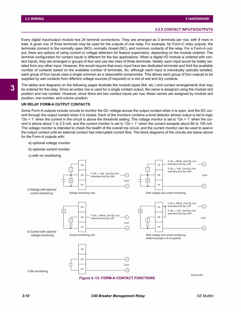
3-10 C60 Breaker Management Relay GE Multilin
3.2 WIRING 3 HARDWARE
3
3.2.5 CONTACT INPUTS/OUTPUTS
Every digital input/output module has 24 terminal connections. They are arranged as 3 terminals per row, with 8 rows intotal. A given row of three terminals may be used for the outputs of one relay. For example, for Form-C relay outputs, theterminals connect to the normally open (NO), normally closed (NC), and common contacts of the relay. For a Form-A out-put, there are options of using current or voltage detection for feature supervision, depending on the module ordered. Theterminal configuration for contact inputs is different for the two applications. When a digital I/O module is ordered with con-tact inputs, they are arranged in groups of four and use two rows of three terminals. Ideally, each input would be totally iso-lated from any other input. However, this would require that every input have two dedicated terminals and limit the availablenumber of contacts based on the available number of terminals. So, although each input is individually optically isolated,each group of four inputs uses a single common as a reasonable compromise. This allows each group of four outputs to besupplied by wet contacts from different voltage sources (if required) or a mix of wet and dry contacts.
The tables and diagrams on the following pages illustrate the module types (6A, etc.) and contact arrangements that maybe ordered for the relay. Since an entire row is used for a single contact output, the name is assigned using the module slotposition and row number. However, since there are two contact inputs per row, these names are assigned by module slotposition, row number, and column position.
UR RELAY FORM-A OUTPUT CONTACTS
Some Form-A outputs include circuits to monitor the DC voltage across the output contact when it is open, and the DC cur-rent through the output contact when it is closed. Each of the monitors contains a level detector whose output is set to logicOn = 1 when the current in the circuit is above the threshold setting. The voltage monitor is set to On = 1 when the cur-rent is above about 1 to 2.5 mA, and the current monitor is set to On = 1 when the current exceeds about 80 to 100 mA.The voltage monitor is intended to check the health of the overall trip circuit, and the current monitor can be used to seal-inthe output contact until an external contact has interrupted current flow. The block diagrams of the circuits are below abovefor the Form-A outputs with:
a) optional voltage monitor
b) optional current monitor
c) with no monitoring
Figure 313: FORM-A CONTACT FUNCTIONS
Load
I
~#a
+
-
~#b
~#c
If Idc 1mA, Cont Op x Vonotherwise Cont Op x Voff
V
~
827821A4.CDR
a) Voltage with optionalcurrent monitoring Voltage monitoring only
Load
I
+
-V
Both voltage and current monitoring
If Idc 80mA, Cont Op x Ionotherwise Cont Op x Ioff
~
If Idc 1mA, Cont Op x Vonotherwise Cont Op x Voff
~
LoadI
+
-
V
b) Current with optionalvoltage monitoring Current monitoring only Both voltage and current monitoring
(external jumper a-b is required)
If Idc 80mA, Cont Op x Ionotherwise Cont Op x Ioff
~Load
I
-
V
+If Idc 80mA, Cont Op x Ionotherwise Cont Op x Ioff
~
If Idc 1mA, Cont Op x Vonotherwise Cont Op x Voff
~
Load
+
-c) No monitoring
~#a
~#b
~#c
~#a
~#b
~#c
~#a
~#b
~#c
~#a
~#b
~#c
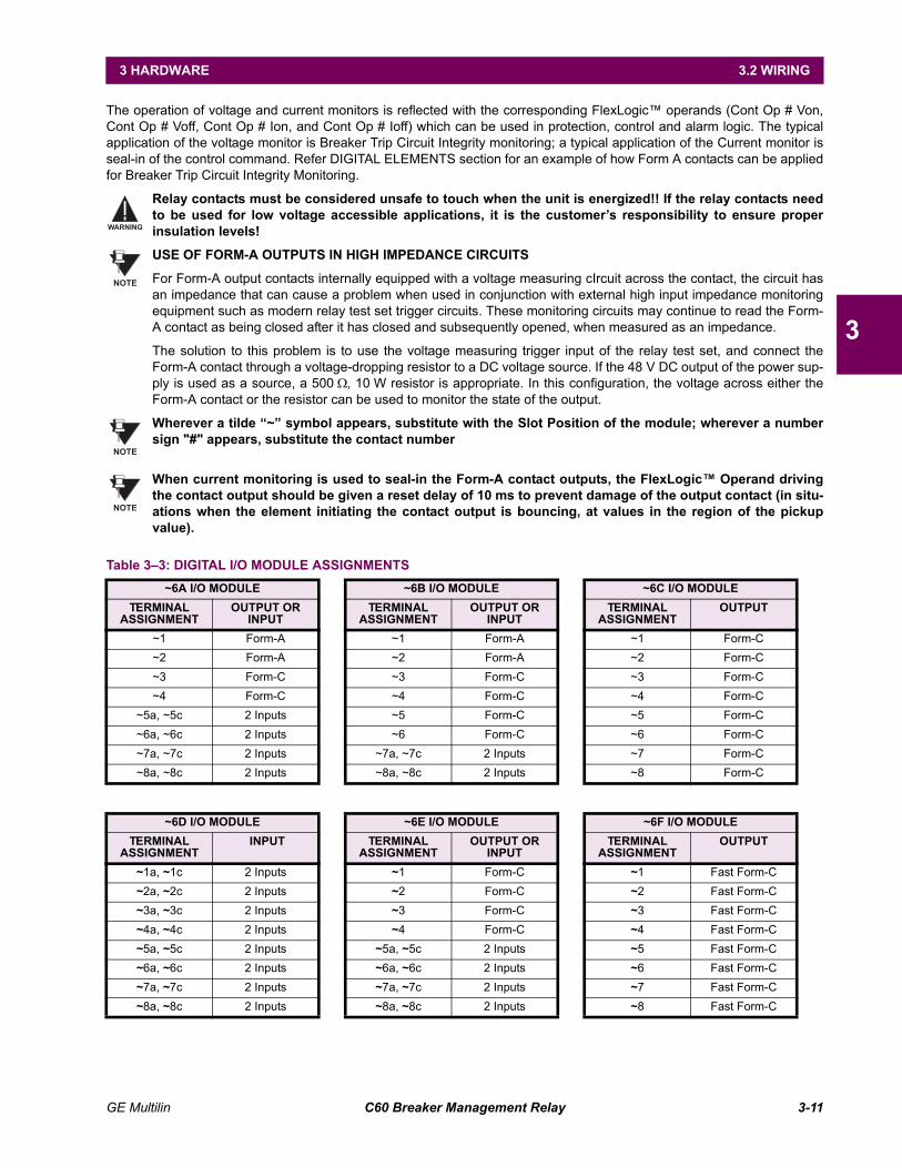
GE Multilin C60 Breaker Management Relay 3-11
3 HARDWARE 3.2 WIRING
3
The operation of voltage and current monitors is reflected with the corresponding FlexLogic operands (Cont Op # Von,Cont Op # Voff, Cont Op # Ion, and Cont Op # Ioff) which can be used in protection, control and alarm logic. The typicalapplication of the voltage monitor is Breaker Trip Circuit Integrity monitoring; a typical application of the Current monitor isseal-in of the control command. Refer DIGITAL ELEMENTS section for an example of how Form A contacts can be appliedfor Breaker Trip Circuit Integrity Monitoring.
Relay contacts must be considered unsafe to touch when the unit is energized!! If the relay contacts needto be used for low voltage accessible applications, it is the customers responsibility to ensure properinsulation levels!
USE OF FORM-A OUTPUTS IN HIGH IMPEDANCE CIRCUITS
For Form-A output contacts internally equipped with a voltage measuring cIrcuit across the contact, the circuit hasan impedance that can cause a problem when used in conjunction with external high input impedance monitoringequipment such as modern relay test set trigger circuits. These monitoring circuits may continue to read the Form-A contact as being closed after it has closed and subsequently opened, when measured as an impedance.
The solution to this problem is to use the voltage measuring trigger input of the relay test set, and connect theForm-A contact through a voltage-dropping resistor to a DC voltage source. If the 48 V DC output of the power sup-ply is used as a source, a 500 Ω, 10 W resistor is appropriate. In this configuration, the voltage across either theForm-A contact or the resistor can be used to monitor the state of the output.
Wherever a tilde ~ symbol appears, substitute with the Slot Position of the module; wherever a numbersign "#" appears, substitute the contact number
When current monitoring is used to seal-in the Form-A contact outputs, the FlexLogic Operand drivingthe contact output should be given a reset delay of 10 ms to prevent damage of the output contact (in situ-ations when the element initiating the contact output is bouncing, at values in the region of the pickupvalue).
Table 33: DIGITAL I/O MODULE ASSIGNMENTS~6A I/O MODULE ~6B I/O MODULE ~6C I/O MODULE
TERMINAL ASSIGNMENT
OUTPUT OR INPUT
TERMINAL ASSIGNMENT
OUTPUT OR INPUT
TERMINAL ASSIGNMENT
OUTPUT
~1 Form-A ~1 Form-A ~1 Form-C~2 Form-A ~2 Form-A ~2 Form-C~3 Form-C ~3 Form-C ~3 Form-C~4 Form-C ~4 Form-C ~4 Form-C
~5a, ~5c 2 Inputs ~5 Form-C ~5 Form-C~6a, ~6c 2 Inputs ~6 Form-C ~6 Form-C~7a, ~7c 2 Inputs ~7a, ~7c 2 Inputs ~7 Form-C~8a, ~8c 2 Inputs ~8a, ~8c 2 Inputs ~8 Form-C
~6D I/O MODULE ~6E I/O MODULE ~6F I/O MODULETERMINAL
ASSIGNMENT INPUT TERMINAL
ASSIGNMENTOUTPUT OR
INPUTTERMINAL
ASSIGNMENTOUTPUT
~1a, ~1c 2 Inputs ~1 Form-C ~1 Fast Form-C~2a, ~2c 2 Inputs ~2 Form-C ~2 Fast Form-C~3a, ~3c 2 Inputs ~3 Form-C ~3 Fast Form-C~4a, ~4c 2 Inputs ~4 Form-C ~4 Fast Form-C~5a, ~5c 2 Inputs ~5a, ~5c 2 Inputs ~5 Fast Form-C~6a, ~6c 2 Inputs ~6a, ~6c 2 Inputs ~6 Fast Form-C~7a, ~7c 2 Inputs ~7a, ~7c 2 Inputs ~7 Fast Form-C~8a, ~8c 2 Inputs ~8a, ~8c 2 Inputs ~8 Fast Form-C
WARNING
NOTE
NOTE
NOTE
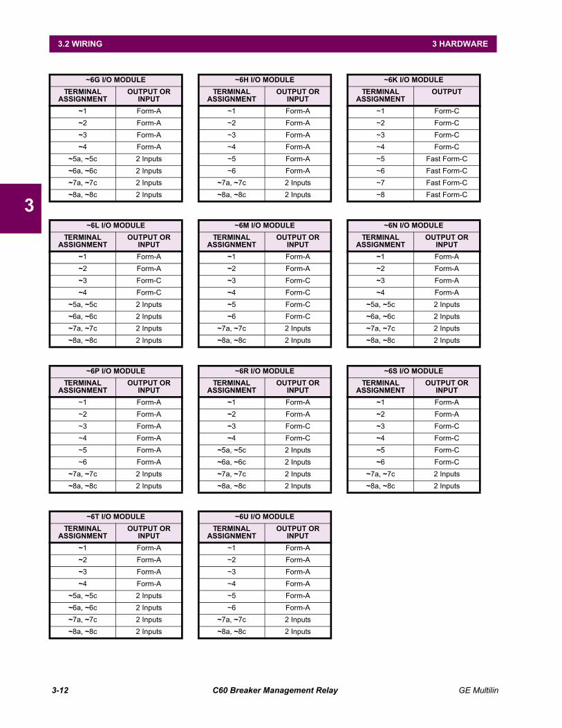
3-12 C60 Breaker Management Relay GE Multilin
3.2 WIRING 3 HARDWARE
3
~6G I/O MODULE ~6H I/O MODULE ~6K I/O MODULETERMINAL
ASSIGNMENTOUTPUT OR
INPUTTERMINAL
ASSIGNMENTOUTPUT OR
INPUTTERMINAL
ASSIGNMENTOUTPUT
~1 Form-A ~1 Form-A ~1 Form-C~2 Form-A ~2 Form-A ~2 Form-C~3 Form-A ~3 Form-A ~3 Form-C~4 Form-A ~4 Form-A ~4 Form-C
~5a, ~5c 2 Inputs ~5 Form-A ~5 Fast Form-C~6a, ~6c 2 Inputs ~6 Form-A ~6 Fast Form-C~7a, ~7c 2 Inputs ~7a, ~7c 2 Inputs ~7 Fast Form-C~8a, ~8c 2 Inputs ~8a, ~8c 2 Inputs ~8 Fast Form-C
~6L I/O MODULE ~6M I/O MODULE ~6N I/O MODULETERMINAL
ASSIGNMENTOUTPUT OR
INPUTTERMINAL
ASSIGNMENTOUTPUT OR
INPUTTERMINAL
ASSIGNMENTOUTPUT OR
INPUT~1 Form-A ~1 Form-A ~1 Form-A~2 Form-A ~2 Form-A ~2 Form-A~3 Form-C ~3 Form-C ~3 Form-A~4 Form-C ~4 Form-C ~4 Form-A
~5a, ~5c 2 Inputs ~5 Form-C ~5a, ~5c 2 Inputs~6a, ~6c 2 Inputs ~6 Form-C ~6a, ~6c 2 Inputs~7a, ~7c 2 Inputs ~7a, ~7c 2 Inputs ~7a, ~7c 2 Inputs~8a, ~8c 2 Inputs ~8a, ~8c 2 Inputs ~8a, ~8c 2 Inputs
~6P I/O MODULE ~6R I/O MODULE ~6S I/O MODULETERMINAL
ASSIGNMENTOUTPUT OR
INPUTTERMINAL
ASSIGNMENTOUTPUT OR
INPUTTERMINAL
ASSIGNMENTOUTPUT OR
INPUT~1 Form-A ~1 Form-A ~1 Form-A~2 Form-A ~2 Form-A ~2 Form-A~3 Form-A ~3 Form-C ~3 Form-C~4 Form-A ~4 Form-C ~4 Form-C~5 Form-A ~5a, ~5c 2 Inputs ~5 Form-C~6 Form-A ~6a, ~6c 2 Inputs ~6 Form-C
~7a, ~7c 2 Inputs ~7a, ~7c 2 Inputs ~7a, ~7c 2 Inputs~8a, ~8c 2 Inputs ~8a, ~8c 2 Inputs ~8a, ~8c 2 Inputs
~6T I/O MODULE ~6U I/O MODULETERMINAL
ASSIGNMENTOUTPUT OR
INPUTTERMINAL
ASSIGNMENTOUTPUT OR
INPUT~1 Form-A ~1 Form-A~2 Form-A ~2 Form-A~3 Form-A ~3 Form-A~4 Form-A ~4 Form-A
~5a, ~5c 2 Inputs ~5 Form-A~6a, ~6c 2 Inputs ~6 Form-A~7a, ~7c 2 Inputs ~7a, ~7c 2 Inputs~8a, ~8c 2 Inputs ~8a, ~8c 2 Inputs
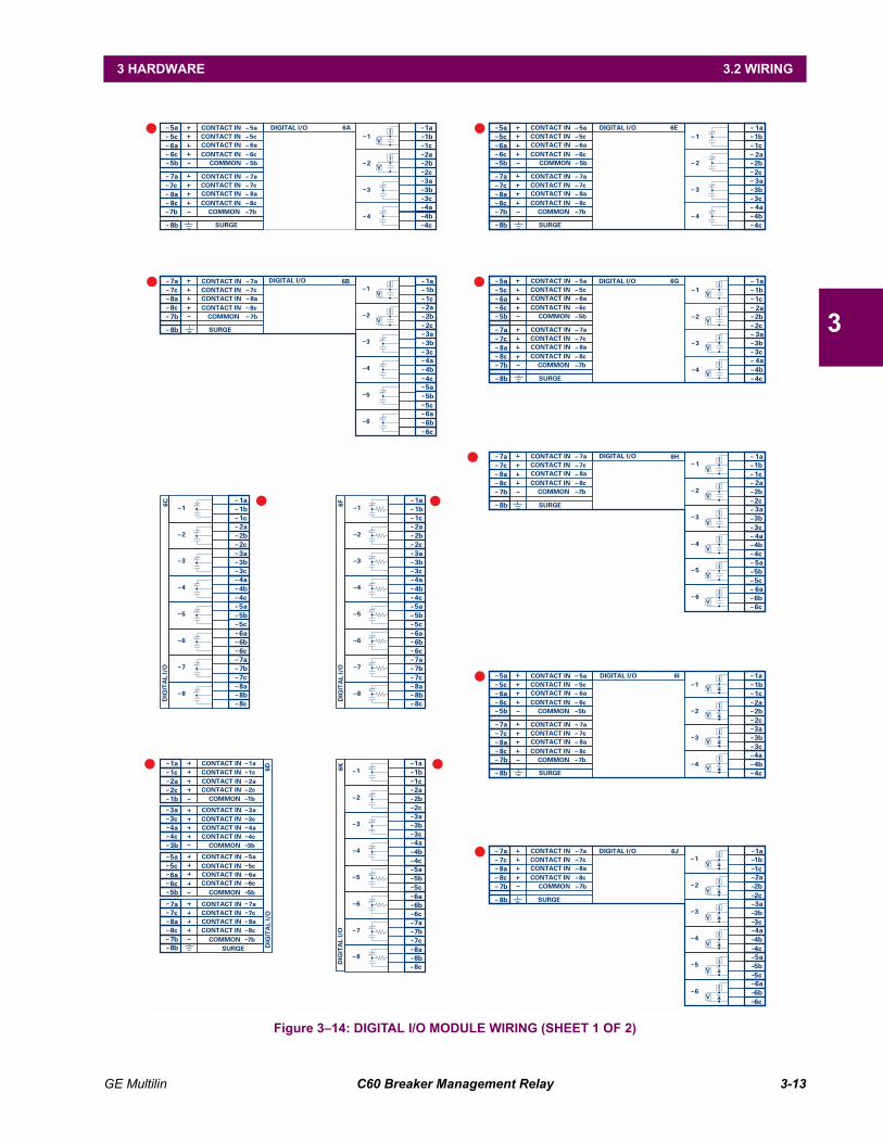
GE Multilin C60 Breaker Management Relay 3-13
3 HARDWARE 3.2 WIRING
3
Figure 314: DIGITAL I/O MODULE WIRING (SHEET 1 OF 2)
1a
2b
1c1b
2c
2a
4a
4c
3b3a
4b
3c
CONTACT IN 5a
CONTACT IN 7a
CONTACT IN 5c
CONTACT IN 7c
CONTACT IN 6a
CONTACT IN 8a
CONTACT IN 6c
CONTACT IN 8c
COMMON 5b
COMMON 7b
SURGE
6a
8a
5b
7b
8b
5a~~~~~
~~~~~
~
~~~~~
~~~~~
~~~
~
~
~
~~~~~~~~~~
7a
6c
8c
5c
7c
1
2
3
4
I
V
I
V
I
V
I
V
DIGITAL I/O 6G
CONTACT IN 5aCONTACT IN 5cCONTACT IN 6aCONTACT IN 6c
COMMON 5b
CONTACT IN 7aCONTACT IN 7cCONTACT IN 8aCONTACT IN 8c
COMMON 7b
SURGE
6a
8a
5b
7b
8b
5a~~~~~
~~~~~
~
~~~~~
~~~~~
~~~
~
~
~
~~~~~~~~~~
7a
6c
8c
5c
7c
1a
2b
1c1b
2c
2a
4a
4c
3b3a
4b
3c
1
2
3
4
DIGITAL I/O 6E
CONTACT IN 7aCONTACT IN 7cCONTACT IN 8aCONTACT IN 8c
COMMON 7b
8a
7b
7a~~~~~
~~~~~
~~~
~
~
~
~
~
~~~~~~~~~~~~~~~~
~
8c
7c 1b
2b
3b
4b
5b
6b
1a
2a
3a
4a
5a
6a
1c
2c
3c
4c
5c
6c
SURGE8b
1
5
2
6
3
4
DIGITAL I/O 6H I
V
I
V
I
V
I
V
I
V
I
V
I
V
I
V
CONTACT IN 7aCONTACT IN 7cCONTACT IN 8aCONTACT IN 8c
COMMON 7b
DIGITAL I/O 6B1b
2b
3b
4b
5b
6b
1a
2a
3a
4a
5a
6a
1c
2c
3c
4c
5c
6c
1
5
2
6
3
4
8a
7b
7a~~ ~ ~~
~
~
~ ~ ~
~~
~
~
~ ~ ~
~
~~
~~
~ ~ ~~
~
~
~
~
~ ~
~
~~
8c
7c
SURGE8b
6CD
IGIT
AL
I/O
1
5
2
6
3
7
4
8
7a
1a
2b
7c
1c
7b
1b
8c
~~~
~
~
~
~
~
~
~
~~~~~~~~~~~~~~~~~~~~~~
8b
2c
8a
2a
4a
5b
4c
6b
3b3a
6a
4b
5c
5a
3c
6c
6a
8a
5b
7b
5a
7a
6c
8c
5c
7c
CONTACT IN 1a
CONTACT IN 4c
COMMON 5b
COMMON 7b
COMMON 1b
COMMON 3b
CONTACT IN 2a
CONTACT IN 5a
CONTACT IN 3c
CONTACT IN 6a
CONTACT IN 8a
CONTACT IN 1c
CONTACT IN 3a
CONTACT IN 5c
CONTACT IN 7cCONTACT IN 7a
CONTACT IN 2c
SURGE
CONTACT IN 4a
CONTACT IN 6c
CONTACT IN 8c
1a
8b
4c
2c
3a3c
1c
3b
1b
4a
2a
6DD
IGIT
AL
I/O
~~ ~~ ~~ ~~ ~~ ~~ ~~ ~~ ~~ ~
~ ~~ ~~ ~~ ~~ ~
~ ~~ ~~ ~~ ~~ ~~
~
6FD
IGIT
AL
I/O
1
5
2
6
3
7
4
8
7a
1a
2b
7c
1c
7b
1b
8c
~~~
~
~
~
~
~
~
~
~~~~~~~~~~~~~~~~~~~~~~
8b
2c
8a
2a
4a
5b
4c
6b
3b3a
6a
4b
5c
5a
3c
6c
7a
1a
2b
7c
1c
7b
1b
8c
~~~
~
~
~
~
~
~
~
~~~~~~~~~~~~~~~~~~~~~~
8b
2c
8a
2a
4a
5b
4c
6b
3b3a
6a
4b
5c
5a
3c
6c
6KD
IGIT
AL
I/O
1
5
2
6
3
7
4
8
CONTACT IN 5a
CONTACT IN 7a
CONTACT IN 5c
CONTACT IN 7c
CONTACT IN 6a
CONTACT IN 8a
CONTACT IN 6c
CONTACT IN 8c
COMMON 5b
COMMON 7b
SURGE
6a
8a
5b
7b
8b
5a~~~~~
~~~~~
~
~~~~~
~~~~~
~~~
~
~
~
~~~~~~~~~~
7a
6c
8c
5c
7c
6A1
2
3
4
1a
2b
1c1b
2c
2a
4a
4c
3b3a
4b
3c
DIGITAL I/O I
V
I
V
CONTACT IN 7aCONTACT IN 7cCONTACT IN 8aCONTACT IN 8c
COMMON 7b
1b
2b
3b
4b
5b
6b
1a
2a
3a
4a
5a
6a
1c
2c
3c
4c
5c
6c
DIGITAL I/O 6J1
5
2
6
3
4
8a
7b
7a~~~~~
~
~~~~~
~~~
~
~
~
~
~
~~~~~~~~~~~~~~~~
8c
7c
SURGE8b
I
V
I
V
I
V
I
V
I
V
I
V
CONTACT IN 5a
CONTACT IN 7a
CONTACT IN 5c
CONTACT IN 7c
CONTACT IN 6a
CONTACT IN 8a
CONTACT IN 6c
CONTACT IN 8c
COMMON 5b
COMMON 7b
SURGE
6a
8a
5b
7b
8b
5a~~~~~
~~~~~
~
~~~
~
~
~
~~~~~~~~~~
~~~~~
~~~~~
7a
6c
8c
5c
7c
1
2
3
4
1a
2b
1c1b
2c
2a
4a
4c
3b3a
4b
3c
6IDIGITAL I/O
I
V
I
V
I
V
I
V
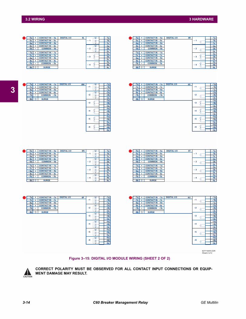
3-14 C60 Breaker Management Relay GE Multilin
3.2 WIRING 3 HARDWARE
3
Figure 315: DIGITAL I/O MODULE WIRING (SHEET 2 OF 2)
CORRECT POLARITY MUST BE OBSERVED FOR ALL CONTACT INPUT CONNECTIONS OR EQUIP-MENT DAMAGE MAY RESULT.
CONTACT IN 5a
CONTACT IN 7a
CONTACT IN 5c
CONTACT IN 7c
CONTACT IN 6a
CONTACT IN 8a
CONTACT IN 6c
CONTACT IN 8c
COMMON 5b
COMMON 7b
SURGE
6a
8a
5b
7b
8b
5a~
~
~
~
~
~~~~~~~~~~~~
~~~~~
~~~~~
~
~~~~~~
~~~~
7a
6c
8c
5c
7c
6L1
2
3
4
1a
2b
1c1b
2c
2a
4a
4c
3b3a
4b
3c
DIGITAL I/OIV
IV
IV
IV
IV
IV
IV
IV
IV
IV
IV
IV
IV
IV
CONTACT IN 7aCONTACT IN 7cCONTACT IN 8aCONTACT IN 8c
COMMON 7b
DIGITAL I/O 6M1b
2b
3b
4b
5b
6b
1a
2a
3a
4a
5a
6a
1c
2c
3c
4c
5c
6c
1
5
2
6
3
4
8a
7b
7a~~ ~ ~~
~
~
~ ~ ~
~~
~
~
~ ~ ~
~
~~
~~
~ ~ ~~
~
~
~
~
~ ~
~
~~
8c
7c
SURGE8b
CONTACT IN 5a
CONTACT IN 7a
CONTACT IN 5c
CONTACT IN 7c
CONTACT IN 6a
CONTACT IN 8a
CONTACT IN 6c
CONTACT IN 8c
COMMON 5b
COMMON 7b
SURGE
6a
8a
5b
7b
8b
5a~
~
~
~
~
~~~~~~~~~~~~
~~~~~
~~~~~
~
~~~~~~
~~~~
7a
6c
8c
5c
7c
6N1
2
3
4
1a
2b
1c1b
2c
2a
4a
4c
3b3a
4b
3c
DIGITAL I/O
CONTACT IN 7aCONTACT IN 7cCONTACT IN 8aCONTACT IN 8c
COMMON 7b
DIGITAL I/O 6P1b
2b
3b
4b
5b
6b
1a
2a
3a
4a
5a
6a
1c
2c
3c
4c
5c
6c
1
5
2
6
3
4
8a
7b
7a~~ ~ ~~
~
~
~ ~ ~
~~
~
~
~ ~ ~
~
~~
~~
~ ~ ~~
~
~
~
~
~ ~
~
~~
8c
7c
SURGE8b
CONTACT IN 5a
CONTACT IN 7a
CONTACT IN 5c
CONTACT IN 7c
CONTACT IN 6a
CONTACT IN 8a
CONTACT IN 6c
CONTACT IN 8c
COMMON 5b
COMMON 7b
SURGE
6a
8a
5b
7b
8b
5a~
~
~
~
~
~~~~~~~~~~~~
~~~~~
~~~~~
~
~~~~~~
~~~~
7a
6c
8c
5c
7c
6R1
2
3
4
1a
2b
1c1b
2c
2a
4a
4c
3b3a
4b
3c
DIGITAL I/O
CONTACT IN 7aCONTACT IN 7cCONTACT IN 8aCONTACT IN 8c
COMMON 7b
DIGITAL I/O 6S1b
2b
3b
4b
5b
6b
1a
2a
3a
4a
5a
6a
1c
2c
3c
4c
5c
6c
1
5
2
6
3
4
8a
7b
7a~~ ~ ~~
~
~
~ ~ ~
~~
~
~
~ ~ ~
~
~~
~~
~ ~ ~~
~
~
~
~
~ ~
~
~~
8c
7c
SURGE8b
CONTACT IN 5a
CONTACT IN 7a
CONTACT IN 5c
CONTACT IN 7c
CONTACT IN 6a
CONTACT IN 8a
CONTACT IN 6c
CONTACT IN 8c
COMMON 5b
COMMON 7b
SURGE
6a
8a
5b
7b
8b
5a~
~
~
~
~
~~~~~~~~~~~~
~~~~~
~~~~~
~
~~~~~~
~~~~
7a
6c
8c
5c
7c
6T1
2
3
4
1a
2b
1c1b
2c
2a
4a
4c
3b3a
4b
3c
DIGITAL I/O
CONTACT IN 7aCONTACT IN 7cCONTACT IN 8aCONTACT IN 8c
COMMON 7b
DIGITAL I/O 6U1b
2b
3b
4b
5b
6b
1a
2a
3a
4a
5a
6a
1c
2c
3c
4c
5c
6c
1
5
2
6
3
4
8a
7b
7a~~ ~ ~~
~
~
~ ~ ~
~~
~
~
~ ~ ~
~
~~
~~
~ ~ ~~
~
~
~
~
~ ~
~
~~
8c
7c
SURGE8b
827719AR.CDR
Sheet 2 of 2
CAUTION

GE Multilin C60 Breaker Management Relay 3-15
3 HARDWARE 3.2 WIRING
3
A dry contact has one side connected to terminal B3b. This is the positive 48 V DC voltage rail supplied by the power sup-ply module. The other side of the dry contact is connected to the required contact input terminal. Each contact input grouphas its own common (negative) terminal which must be connected to the DC negative terminal (B3a) of the power supplymodule. When a dry contact closes, a current of 1 to 3 mA will flow through the associated circuit.
A wet contact has one side connected to the positive terminal of an external DC power supply. The other side of this contactis connected to the required contact input terminal. In addition, the negative side of the external source must be connectedto the relay common (negative) terminal of each contact input group. The maximum external source voltage for thisarrangement is 300 V DC.
The voltage threshold at which each group of four contact inputs will detect a closed contact input is programmable as17 V DC for 24 V sources, 33 V DC for 48 V sources, 84 V DC for 110 to 125 V sources, and 166 V DC for 250 V sources.
Figure 316: DRY AND WET CONTACT INPUT CONNECTIONS
Wherever a tilde ~ symbol appears, substitute with the Slot Position of the module.
Contact outputs may be ordered as Form-A or Form-C. The Form A contacts may be connected for external circuit supervi-sion. These contacts are provided with voltage and current monitoring circuits used to detect the loss of DC voltage in thecircuit, and the presence of DC current flowing through the contacts when the Form-A contact closes. If enabled, the cur-rent monitoring can be used as a seal-in signal to ensure that the Form-A contact does not attempt to break the energizedinductive coil circuit and weld the output contacts.
827741A4.CDR
CRITICALFAILURE
1bBBBBBBBBBB
1a2b3a -3b +
-
5b HI+6b LO+6a8a8b
48 VDCOUTPUT
CONTROLPOWER
SURGEFILTER PO
WER
SU
PPLY
1
24-250V
(Wet)(Dry)7a
DIGITAL I/O 6B~
~~~~~
~
~~~~~
~~~~~
~
~~~~ 7c
8a8c7b
+
-
8b
++
+
CONTACT IN 7aCONTACT IN 7cCONTACT IN 8aCONTACT IN 8c
COMMON 7b
SURGE
7aDIGITAL I/O 6B
7c8a8c7b
+
-
8b
++
+
CONTACT IN 7aCONTACT IN 7cCONTACT IN 8aCONTACT IN 8c
COMMON 7b
SURGE
NOTE
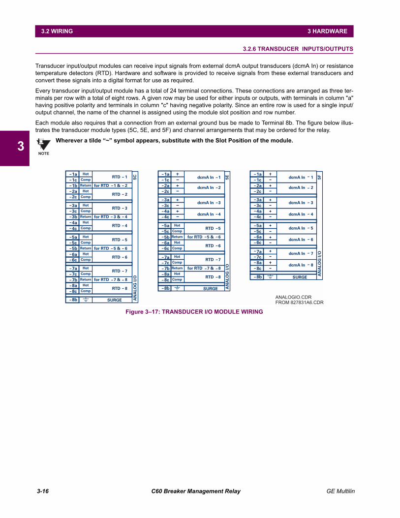
3-16 C60 Breaker Management Relay GE Multilin
3.2 WIRING 3 HARDWARE
3
3.2.6 TRANSDUCER INPUTS/OUTPUTS
Transducer input/output modules can receive input signals from external dcmA output transducers (dcmA In) or resistancetemperature detectors (RTD). Hardware and software is provided to receive signals from these external transducers andconvert these signals into a digital format for use as required.
Every transducer input/output module has a total of 24 terminal connections. These connections are arranged as three ter-minals per row with a total of eight rows. A given row may be used for either inputs or outputs, with terminals in column "a"having positive polarity and terminals in column "c" having negative polarity. Since an entire row is used for a single input/output channel, the name of the channel is assigned using the module slot position and row number.
Each module also requires that a connection from an external ground bus be made to Terminal 8b. The figure below illus-trates the transducer module types (5C, 5E, and 5F) and channel arrangements that may be ordered for the relay.
Wherever a tilde ~ symbol appears, substitute with the Slot Position of the module.
Figure 317: TRANSDUCER I/O MODULE WIRING
NOTE
Hot
Hot
Comp
Comp
Return
Return
Hot
Hot
Comp
Comp
RTD 5
RTD 7
RTD 6
RTD 8
for RTD 5 & 6
for RTD 7 & 8
Hot
Hot
Comp
Comp
Return
Return
Hot
Hot
Comp
Comp
RTD 1
RTD 3
RTD 2
RTD 4
for RTD 1 & 2
for RTD 3 & 4
5a
7a
5b
7b
8c
4a
6a
5c
7c
8a
4c
6c
SURGE
1a
8b
3b
2a2c
3a
1c
3c
1b
5CA
NA
LOG
I/O
~~ ~
~ ~~~~ ~
~~
~
~ ~~~~ ~
~~ ~
~ ~~~~ ~
~~
~
~ ~~~~
~
~
Hot
Hot
Comp
Comp
Return
Return
Hot
Hot
Comp
Comp
dcmA In 1
dcmA In 2
dcmA In 3
dcmA In 4
RTD 5
RTD 7
RTD 6
RTD 8
for RTD 5 & 6
for RTD 7 & 8
5b
7b
6c
8c
5a
7a
6a
8a
5c
7c
SURGE
1a
8b
4c
2c
3a3c
1c
4a
2a
5EA
NA
LOG
I/O
~~ ~
~~
~
~~ ~
~~ ~
~~ ~
~ ~~~~ ~
~~
~
~ ~~~~
~
~
dcmA In 1
dcmA In 5
dcmA In 2
dcmA In 6
dcmA In 3
dcmA In 7
dcmA In 4
dcmA In 8
6c
5a
6a5c
1a
4c
2c
3a3c
1c
4a
2a
5FA
NA
LOG
I/O
~
~
~
~
~
~
~
~
~
~
~~~~
~~~~
~~~~
~~~
8c
7a
8a7c
SURGE8b
ANALOGIO.CDR
FROM 827831A6.CDR
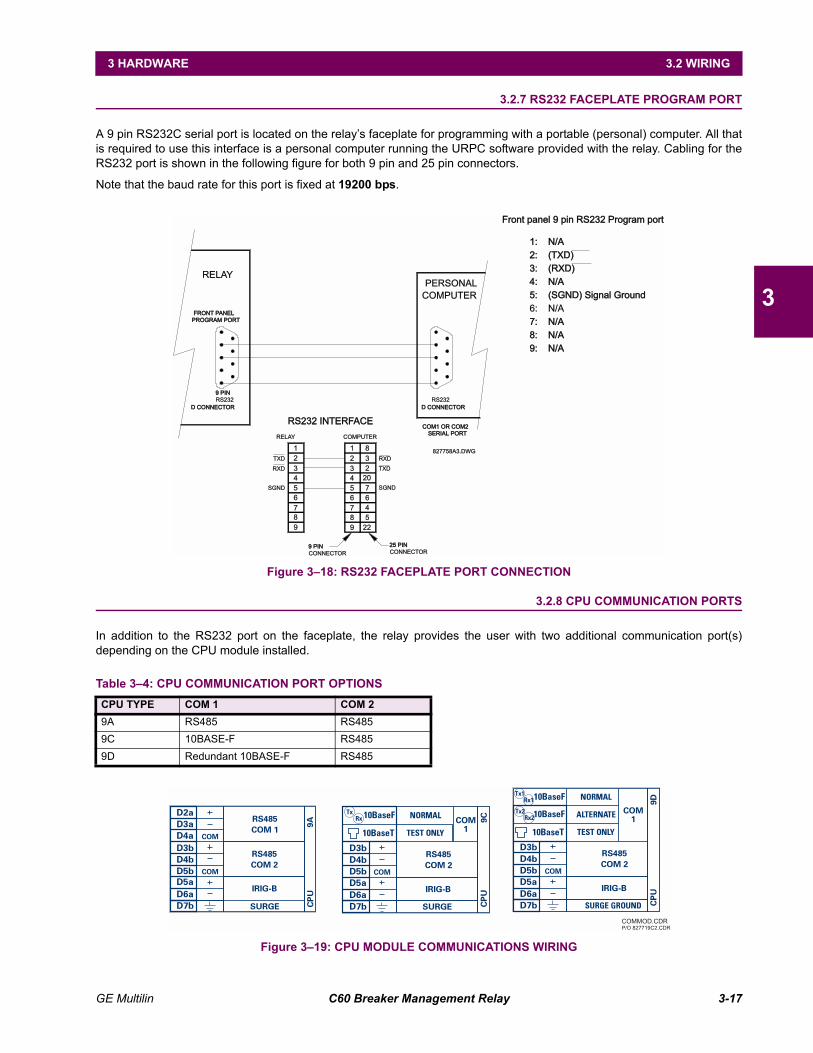
GE Multilin C60 Breaker Management Relay 3-17
3 HARDWARE 3.2 WIRING
3
3.2.7 RS232 FACEPLATE PROGRAM PORT
A 9 pin RS232C serial port is located on the relays faceplate for programming with a portable (personal) computer. All thatis required to use this interface is a personal computer running the URPC software provided with the relay. Cabling for theRS232 port is shown in the following figure for both 9 pin and 25 pin connectors.
Note that the baud rate for this port is fixed at 19200 bps.
Figure 318: RS232 FACEPLATE PORT CONNECTION
3.2.8 CPU COMMUNICATION PORTS
In addition to the RS232 port on the faceplate, the relay provides the user with two additional communication port(s)depending on the CPU module installed.
Figure 319: CPU MODULE COMMUNICATIONS WIRING
Table 34: CPU COMMUNICATION PORT OPTIONSCPU TYPE COM 1 COM 29A RS485 RS4859C 10BASE-F RS4859D Redundant 10BASE-F RS485
COM1 OR COM2COM1 OR COM2
RELAYPERSONAL
COMPUTER
SERIAL PORTSERIAL PORT
RS232
D CONNECTORD CONNECTORD CONNECTORD CONNECTOR
RS232
9 PIN9 PIN
PROGRAM PORTPROGRAM PORT
FRONT PANELFRONT PANEL
1
2
3
4
5
7
8
9
8
3
2
20
7
6
4
5
22
6
9
8
7
6
5
4
3
2
1
TXD
RXD
SGND
RXD
TXD
SGND
RELAY COMPUTER
RS232 INTERFACERS232 INTERFACE
9 PIN9 PIN
CONNECTOR
25 PIN25 PIN
CONNECTOR
827758A3.DWG
Front panel 9 pin RS232 Program portFront panel 9 pin RS232 Program port
1: N/A1: N/A
2: (TXD)2: (TXD)
3: (RXD)3: (RXD)
4: N/A4: N/A
5: (SGND) Signal Ground5: (SGND) Signal Ground
6: N/A
7: N/A7: N/A
8: N/A8: N/A
9: N/A9: N/A
9A
COM
COM
CP
U
D3b
D4b
D5b
D2a
D3a
D4a
D5a
D6a
D7b
RS485
COM 1
RS485
COM 2
IRIG-B
SURGE SURGE
10BaseT
10BaseF
COM
CP
U9
C
TEST ONLY
NORMAL
RS485
COM 2
IRIG-B
Tx
Rx
D7b
D6a
D4b
D5b
D3b
D5a
COM
1
Tx1
Tx2
Rx1
Rx2
SURGE GROUNDD7b
D6a
D4b
D5b
D3b
10BaseT
10BaseF
10BaseF
D5a
COM
CP
U9
D
COM
1
TEST ONLY
ALTERNATE
NORMAL
RS485
COM 2
IRIG-B
COMMOD.CDR
P/O 827719C2.CDR
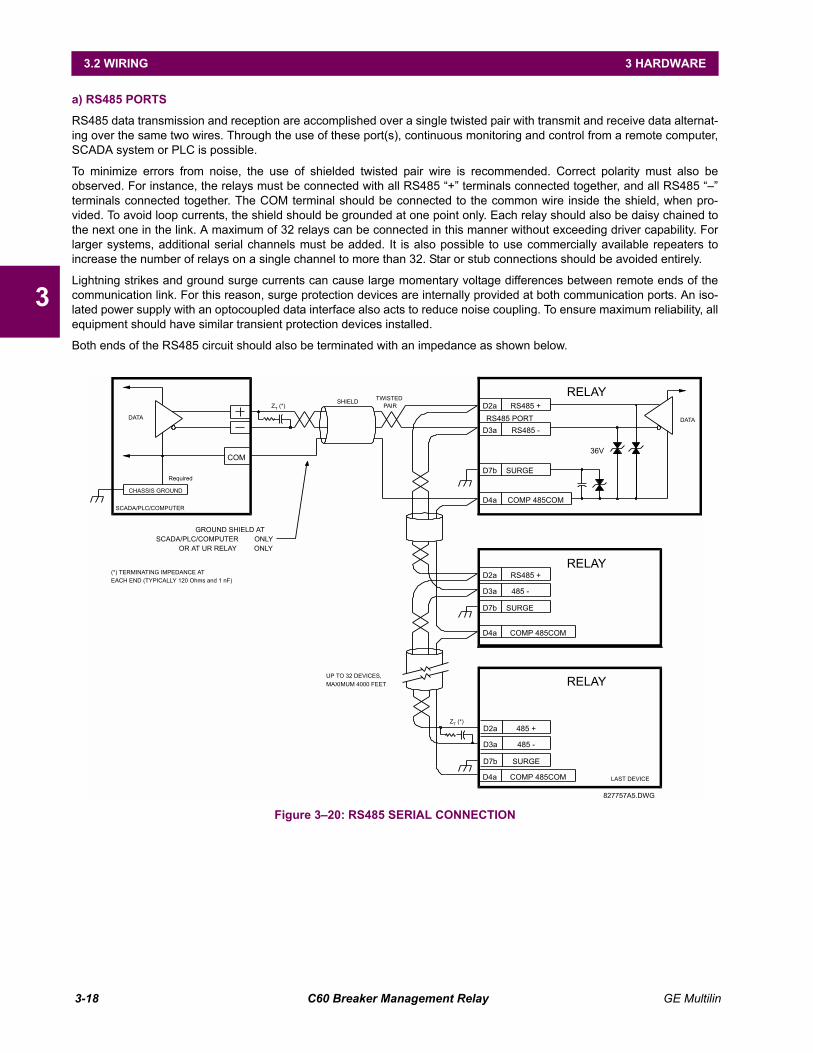
3-18 C60 Breaker Management Relay GE Multilin
3.2 WIRING 3 HARDWARE
3
a) RS485 PORTS
RS485 data transmission and reception are accomplished over a single twisted pair with transmit and receive data alternat-ing over the same two wires. Through the use of these port(s), continuous monitoring and control from a remote computer,SCADA system or PLC is possible.
To minimize errors from noise, the use of shielded twisted pair wire is recommended. Correct polarity must also beobserved. For instance, the relays must be connected with all RS485 + terminals connected together, and all RS485 terminals connected together. The COM terminal should be connected to the common wire inside the shield, when pro-vided. To avoid loop currents, the shield should be grounded at one point only. Each relay should also be daisy chained tothe next one in the link. A maximum of 32 relays can be connected in this manner without exceeding driver capability. Forlarger systems, additional serial channels must be added. It is also possible to use commercially available repeaters toincrease the number of relays on a single channel to more than 32. Star or stub connections should be avoided entirely.
Lightning strikes and ground surge currents can cause large momentary voltage differences between remote ends of thecommunication link. For this reason, surge protection devices are internally provided at both communication ports. An iso-lated power supply with an optocoupled data interface also acts to reduce noise coupling. To ensure maximum reliability, allequipment should have similar transient protection devices installed.
Both ends of the RS485 circuit should also be terminated with an impedance as shown below.
Figure 320: RS485 SERIAL CONNECTION
DATA
SCADA/PLC/COMPUTER
COM
CHASSIS GROUND
DATA
RELAYSHIELD
827757A5.DWG
UP TO 32 DEVICES,
MAXIMUM 4000 FEET
LAST DEVICE
ZT
(*) PAIR
EACH END (TYPICALLY 120 Ohms and 1 nF)
(*) TERMINATING IMPEDANCE AT
TWISTED
ZT
(*)
Required
D2a RS485 +
RS485 -D3a
RS485 PORT
SURGED7b
COMP 485COMD4a
RS485 +D2a
485 -D3a
SURGED7b
COMP 485COMD4a
RELAY
485 +D2a
RELAY
485 -D3a
SURGED7b
COMP 485COMD4a
GROUND SHIELD AT
SCADA/PLC/COMPUTER ONLY
OR AT UR RELAY ONLY
36V
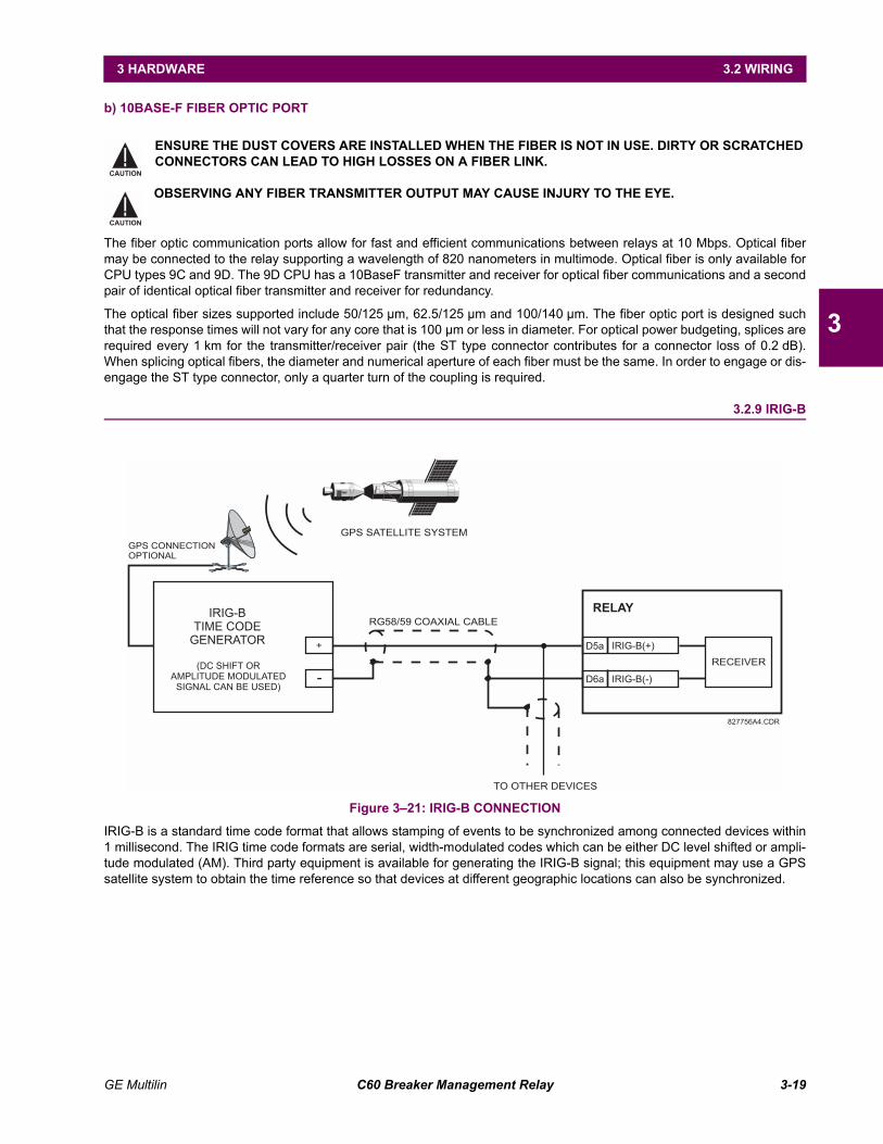
GE Multilin C60 Breaker Management Relay 3-19
3 HARDWARE 3.2 WIRING
3
b) 10BASE-F FIBER OPTIC PORT
The fiber optic communication ports allow for fast and efficient communications between relays at 10 Mbps. Optical fibermay be connected to the relay supporting a wavelength of 820 nanometers in multimode. Optical fiber is only available forCPU types 9C and 9D. The 9D CPU has a 10BaseF transmitter and receiver for optical fiber communications and a secondpair of identical optical fiber transmitter and receiver for redundancy.
The optical fiber sizes supported include 50/125 µm, 62.5/125 µm and 100/140 µm. The fiber optic port is designed suchthat the response times will not vary for any core that is 100 µm or less in diameter. For optical power budgeting, splices arerequired every 1 km for the transmitter/receiver pair (the ST type connector contributes for a connector loss of 0.2 dB).When splicing optical fibers, the diameter and numerical aperture of each fiber must be the same. In order to engage or dis-engage the ST type connector, only a quarter turn of the coupling is required.
3.2.9 IRIG-B
Figure 321: IRIG-B CONNECTION
IRIG-B is a standard time code format that allows stamping of events to be synchronized among connected devices within1 millisecond. The IRIG time code formats are serial, width-modulated codes which can be either DC level shifted or ampli-tude modulated (AM). Third party equipment is available for generating the IRIG-B signal; this equipment may use a GPSsatellite system to obtain the time reference so that devices at different geographic locations can also be synchronized.
ENSURE THE DUST COVERS ARE INSTALLED WHEN THE FIBER IS NOT IN USE. DIRTY OR SCRATCHEDCONNECTORS CAN LEAD TO HIGH LOSSES ON A FIBER LINK.
OBSERVING ANY FIBER TRANSMITTER OUTPUT MAY CAUSE INJURY TO THE EYE.CAUTION
CAUTION
RELAY
IRIG-B(-)
RECEIVER
TO OTHER DEVICES
RG58/59 COAXIAL CABLE
GPS SATELLITE SYSTEM
GPS CONNECTION
OPTIONAL
IRIG-B(+)D5a
D6a
+
-
827756A4.CDR
IRIG-B
TIME CODE
GENERATOR
(DC SHIFT OR
AMPLITUDE MODULATED
SIGNAL CAN BE USED)

3-20 C60 Breaker Management Relay GE Multilin
3.2 WIRING 3 HARDWARE
3

GE Multilin C60 Breaker Management Relay 4-1
4 HUMAN INTERFACES 4.1 URPC® SOFTWARE INTERFACE
4
4 HUMAN INTERFACES 4.1 URPC® SOFTWARE INTERFACE 4.1.1 GRAPHICAL USER INTERFACE
The URPC software provides a graphical user interface (GUI) as one of two human interfaces to a UR device. The alternatehuman interface is implemented via the devices faceplate keypad and display (see FACEPLATE INTERFACE section inthis chapter).
URPC provides a single facility to configure, monitor, maintain, and trouble-shoot the operation of relay functions, con-nected over local or wide area communication networks. It can be used while disconnected (i.e. off-line) or connected (i.e.on-line) to a UR device. In off-line mode, settings files can be created for eventual downloading to the device. In on-linemode, you can communicate with the device in real-time.
The URPC software, provided with every C60 relay, can be run from any computer supporting Microsoft Windows® 95, 98,or NT. This chapter provides a summary of the basic URPC software interface features. The URPC Help file providesdetails for getting started and using the URPC software interface.
4.1.2 CREATING A SITE LIST
To start using the URPC program, a Site List must first be created. See the instructions in the URPC Help program underthe topic Creating a Site List.
4.1.3 URPC® SOFTWARE OVERVIEW
a) ENGAGING A COMMUNICATING DEVICE
The URPC software may be used in on-line mode (relay connected) to directly communicate with a UR relay. Communicat-ing relays are organized and grouped by communication interfaces and into sites. Sites may contain any number of relaysselected from the UR product series.
b) USING SETTINGS FILES
The URPC software interface supports three ways of handling changes to relay settings:
In off-line mode (relay disconnected) to create or edit relay settings files for later download to communicating relays.
While connected to a communicating relay to directly modify any relay settings via relay data view windows, and thensave the settings to the relay.
You can create/edit settings files and then write them to the relay while the interface is connected to the relay.
Settings files are organized on the basis of file names assigned by the user. A settings file contains data pertaining to thefollowing types of relay settings:
Device Definition
Product Setup
System Setup
FlexLogic
Grouped Elements
Control Elements
Inputs/Outputs
Testing
Factory default values are supplied and can be restored after any changes.
c) CREATING / EDITING FLEXLOGIC EQUATIONS
You can create or edit a FlexLogic equation in order to customize the relay. You can subsequently view the automaticallygenerated logic diagram.
d) VIEWING ACTUAL VALUES
You can view real-time relay data such as input/output status and measured parameters.
4-2 C60 Breaker Management Relay GE Multilin
4.1 URPC® SOFTWARE INTERFACE 4 HUMAN INTERFACES
4
e) VIEWING TRIGGERED EVENTS
While the interface is in either on-line or off-line mode, you can view and analyze data generated by triggered specifiedparameters, via:
Event Recorder facility
The event recorder captures contextual data associated with the last 1024 events, listed in chronological order frommost recent to oldest.
Oscillography facility
The oscillography waveform traces and digital states are used to provide a visual display of power system and relayoperation data captured during specific triggered events.
f) CREATING INTERACTIVE SINGLE LINE DIAGRAMS
The URPC® software provides an icon-based interface facility for designing and monitoring electrical schematic diagramsof sites employing UR relays.
g) FILE SUPPORT
Execution
Any URPC file which is double clicked or opened will launch the application, or provide focus to the already openedapplication. If the file was a settings file (*.urs) which had been removed from the Settings List tree menu, it will beadded back to the Settings List tree menu.
Drag and Drop
The Site List and Settings List control bar windows are each mutually a drag source and a drop target for device-order-code-compatible files or individual menu items. Also, the Settings List control bar window and any Windows Explorerdirectory folder are each mutually a file drag source and drop target.
New files which are dropped into the Settings List window are added to the tree which is automatically sorted alphabet-ically with respect to settings file names. Files or individual menu items which are dropped in the selected device menuin the Site List window will automatically be sent to the on-line communicating device.
h) UR FIRMWARE UPGRADES
The firmware of a UR device can be upgraded, locally or remotely, via the URPC® software. The corresponding instructionsare provided by the URPC® Help program under the topic Upgrading Firmware.
Modbus addresses assigned to firmware modules, features, settings, and corresponding data items (i.e. defaultvalues, min/max values, data type, and item size) may change slightly from version to version of firmware. Theaddresses are rearranged when new features are added or existing features are enhanced or modified. TheEEPROM DATA ERROR message displayed after upgrading/downgrading the firmware is a resettable, self-testmessage intended to inform users that the Modbus addresses have changed with the upgraded firmware. Thismessage does not signal any problems when appearing after firmware upgrades.
NOTE

GE Multilin C60 Breaker Management Relay 4-3
4 HUMAN INTERFACES 4.1 URPC® SOFTWARE INTERFACE
4
4.1.4 URPC® SOFTWARE MAIN WINDOW
The URPC software main window supports the following primary display components:
a. Title bar which shows the pathname of the active data view
b. Main window menu bar
c. Main window tool bar
d. Site List control bar window
e. Settings List control bar window
f. Device data view window(s), with common tool bar
g. Settings File data view window(s), with common tool bar
h. Workspace area with data view tabs
i. Status bar
Figure 41: URPC SOFTWARE MAIN WINDOW
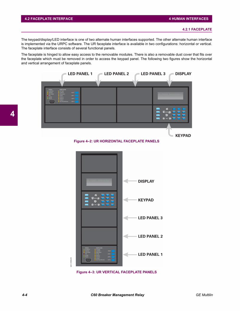
4-4 C60 Breaker Management Relay GE Multilin
4.2 FACEPLATE INTERFACE 4 HUMAN INTERFACES
4
4.2 FACEPLATE INTERFACE 4.2.1 FACEPLATE
The keypad/display/LED interface is one of two alternate human interfaces supported. The other alternate human interfaceis implemented via the URPC software. The UR faceplate interface is available in two configurations: horizontal or vertical.The faceplate interface consists of several functional panels.
The faceplate is hinged to allow easy access to the removable modules. There is also a removable dust cover that fits overthe faceplate which must be removed in order to access the keypad panel. The following two figures show the horizontaland vertical arrangement of faceplate panels.
Figure 42: UR HORIZONTAL FACEPLATE PANELS
Figure 43: UR VERTICAL FACEPLATE PANELS
MENU
HELP
ESCAPE
ENTER VALUE
MESSAGE 4
7
1
.
5
8
2
0
6
9
3
+/-
PICKUP
ALARM
TRIP
TEST MODE
TROUBLE
IN SERVICE
STATUS
USER 3
USER 2
USER 1
RESET
NEUTRAL/GROUND
PHASE C
PHASE B
PHASE A
OTHER
FREQUENCY
CURRENT
VOLTAGE
EVENT CAUSE
LED PANEL 1
KEYPAD
DISPLAYLED PANEL 2 LED PANEL 3
827830A1.C
DR
MENU
HELP
ESCAPE
ENTER VALUE
MESSAGE 4
7
1
.
5
8
2
0
6
9
3
+/-
PICKUP
ALARM
TRIP
TEST MODE
TROUBLE
IN SERVICE
STATUS
USER 3
USER 2
USER 1
RESET
NEUTRAL/GROUND
PHASE C
PHASE B
PHASE A
OTHER
FREQUENCY
CURRENT
VOLTAGE
EVENT CAUSE
KEYPAD
DISPLAY
LED PANEL 2
LED PANEL 3
LED PANEL 1
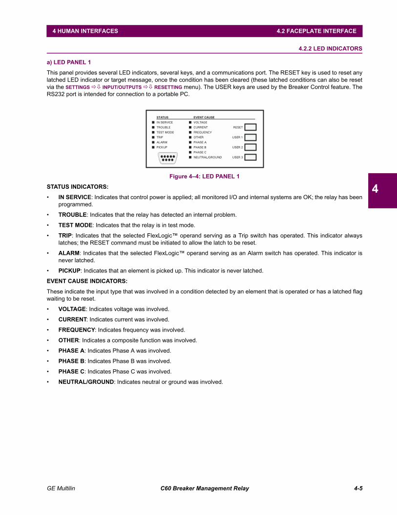
GE Multilin C60 Breaker Management Relay 4-5
4 HUMAN INTERFACES 4.2 FACEPLATE INTERFACE
4
4.2.2 LED INDICATORS
a) LED PANEL 1
This panel provides several LED indicators, several keys, and a communications port. The RESET key is used to reset anylatched LED indicator or target message, once the condition has been cleared (these latched conditions can also be resetvia the SETTINGS !" INPUT/OUTPUTS !" RESETTING menu). The USER keys are used by the Breaker Control feature. TheRS232 port is intended for connection to a portable PC.
Figure 44: LED PANEL 1
STATUS INDICATORS:
IN SERVICE: Indicates that control power is applied; all monitored I/O and internal systems are OK; the relay has beenprogrammed.
TROUBLE: Indicates that the relay has detected an internal problem.
TEST MODE: Indicates that the relay is in test mode.
TRIP: Indicates that the selected FlexLogic operand serving as a Trip switch has operated. This indicator alwayslatches; the RESET command must be initiated to allow the latch to be reset.
ALARM: Indicates that the selected FlexLogic operand serving as an Alarm switch has operated. This indicator isnever latched.
PICKUP: Indicates that an element is picked up. This indicator is never latched.
EVENT CAUSE INDICATORS:
These indicate the input type that was involved in a condition detected by an element that is operated or has a latched flagwaiting to be reset.
VOLTAGE: Indicates voltage was involved.
CURRENT: Indicates current was involved.
FREQUENCY: Indicates frequency was involved.
OTHER: Indicates a composite function was involved.
PHASE A: Indicates Phase A was involved.
PHASE B: Indicates Phase B was involved.
PHASE C: Indicates Phase C was involved.
NEUTRAL/GROUND: Indicates neutral or ground was involved.
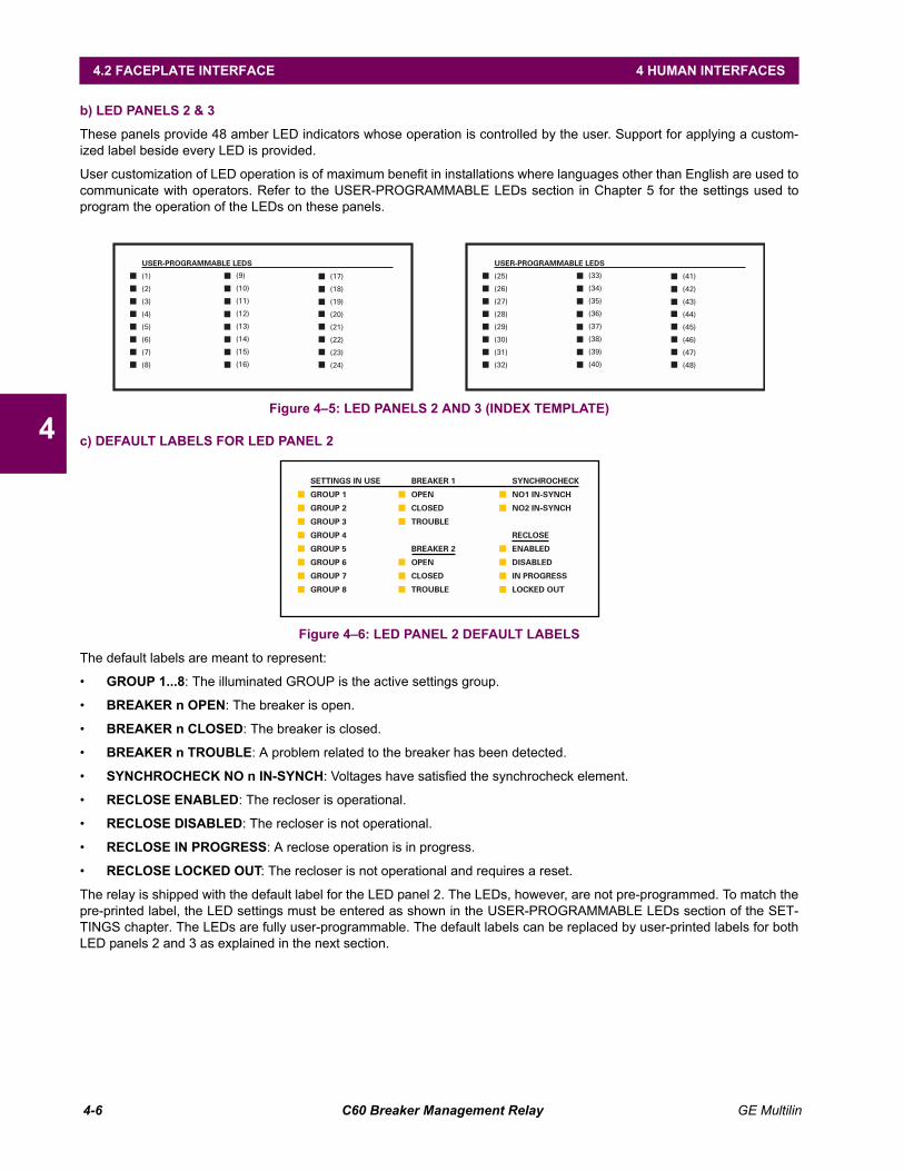
4-6 C60 Breaker Management Relay GE Multilin
4.2 FACEPLATE INTERFACE 4 HUMAN INTERFACES
4
b) LED PANELS 2 & 3
These panels provide 48 amber LED indicators whose operation is controlled by the user. Support for applying a custom-ized label beside every LED is provided.
User customization of LED operation is of maximum benefit in installations where languages other than English are used tocommunicate with operators. Refer to the USER-PROGRAMMABLE LEDs section in Chapter 5 for the settings used toprogram the operation of the LEDs on these panels.
Figure 45: LED PANELS 2 AND 3 (INDEX TEMPLATE)
c) DEFAULT LABELS FOR LED PANEL 2
Figure 46: LED PANEL 2 DEFAULT LABELS
The default labels are meant to represent:
GROUP 1...8: The illuminated GROUP is the active settings group.
BREAKER n OPEN: The breaker is open.
BREAKER n CLOSED: The breaker is closed.
BREAKER n TROUBLE: A problem related to the breaker has been detected.
SYNCHROCHECK NO n IN-SYNCH: Voltages have satisfied the synchrocheck element.
RECLOSE ENABLED: The recloser is operational.
RECLOSE DISABLED: The recloser is not operational.
RECLOSE IN PROGRESS: A reclose operation is in progress.
RECLOSE LOCKED OUT: The recloser is not operational and requires a reset.
The relay is shipped with the default label for the LED panel 2. The LEDs, however, are not pre-programmed. To match thepre-printed label, the LED settings must be entered as shown in the USER-PROGRAMMABLE LEDs section of the SET-TINGS chapter. The LEDs are fully user-programmable. The default labels can be replaced by user-printed labels for bothLED panels 2 and 3 as explained in the next section.
GROUP 8
GROUP 7
GROUP 6
GROUP 5
GROUP 4
GROUP 3
GROUP 2
GROUP 1
SETTINGS IN USE
LOCKED OUT
IN PROGRESS
DISABLED
ENABLED
RECLOSE
NO2 IN-SYNCH
NO1 IN-SYNCH
SYNCHROCHECK
TROUBLE
CLOSED
OPEN
BREAKER 2
TROUBLE
CLOSED
OPEN
BREAKER 1
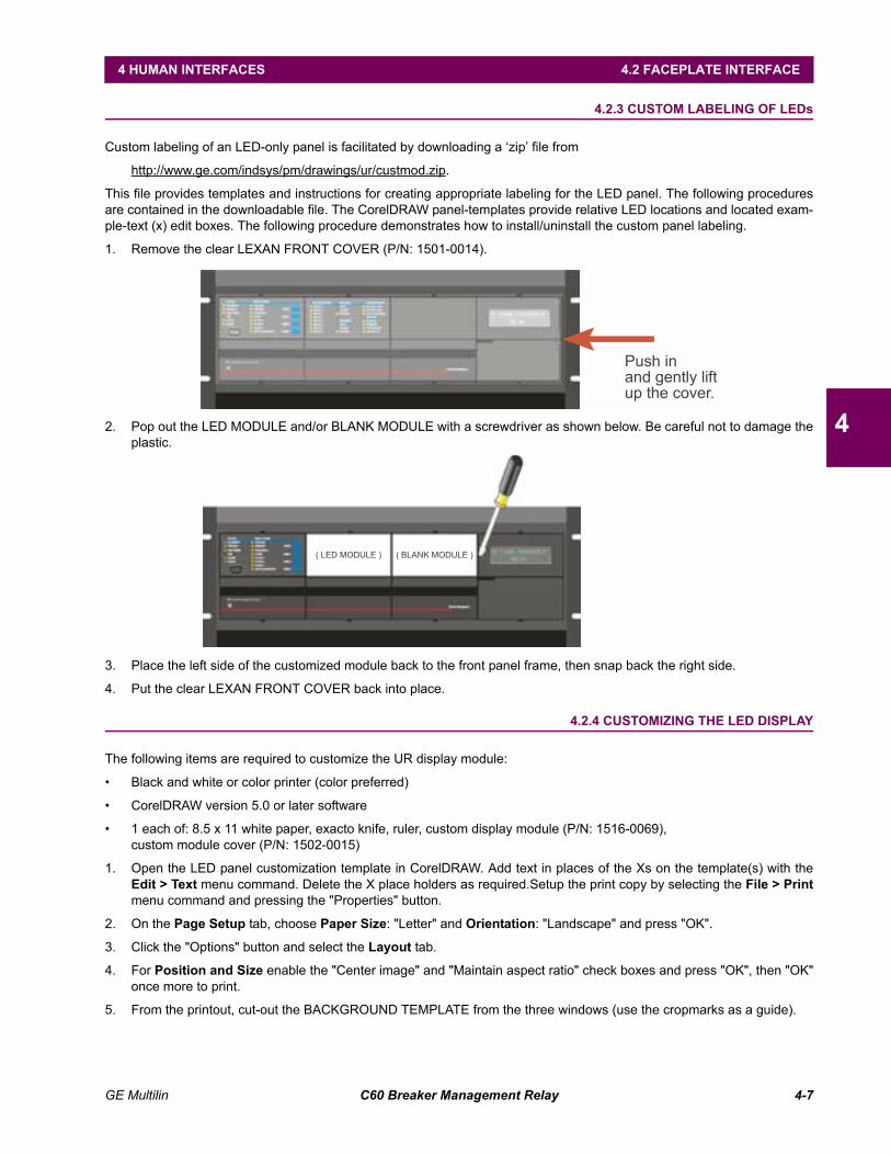
GE Multilin C60 Breaker Management Relay 4-7
4 HUMAN INTERFACES 4.2 FACEPLATE INTERFACE
4
4.2.3 CUSTOM LABELING OF LEDs
Custom labeling of an LED-only panel is facilitated by downloading a zip file from
http://www.ge.com/indsys/pm/drawings/ur/custmod.zip.
This file provides templates and instructions for creating appropriate labeling for the LED panel. The following proceduresare contained in the downloadable file. The CorelDRAW panel-templates provide relative LED locations and located exam-ple-text (x) edit boxes. The following procedure demonstrates how to install/uninstall the custom panel labeling.
1. Remove the clear LEXAN FRONT COVER (P/N: 1501-0014).
2. Pop out the LED MODULE and/or BLANK MODULE with a screwdriver as shown below. Be careful not to damage theplastic.
3. Place the left side of the customized module back to the front panel frame, then snap back the right side.
4. Put the clear LEXAN FRONT COVER back into place.
4.2.4 CUSTOMIZING THE LED DISPLAY
The following items are required to customize the UR display module:
Black and white or color printer (color preferred)
CorelDRAW version 5.0 or later software
1 each of: 8.5 x 11 white paper, exacto knife, ruler, custom display module (P/N: 1516-0069),custom module cover (P/N: 1502-0015)
1. Open the LED panel customization template in CorelDRAW. Add text in places of the Xs on the template(s) with theEdit > Text menu command. Delete the X place holders as required.Setup the print copy by selecting the File > Printmenu command and pressing the "Properties" button.
2. On the Page Setup tab, choose Paper Size: "Letter" and Orientation: "Landscape" and press "OK".
3. Click the "Options" button and select the Layout tab.
4. For Position and Size enable the "Center image" and "Maintain aspect ratio" check boxes and press "OK", then "OK"once more to print.
5. From the printout, cut-out the BACKGROUND TEMPLATE from the three windows (use the cropmarks as a guide).
Push in
and gently lift
up the cover.
( LED MODULE ) ( BLANK MODULE )
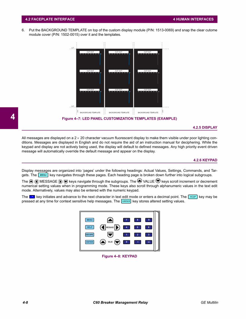
4-8 C60 Breaker Management Relay GE Multilin
4.2 FACEPLATE INTERFACE 4 HUMAN INTERFACES
4
6. Put the BACKGROUND TEMPLATE on top of the custom display module (P/N: 1513-0069) and snap the clear cutomemodule cover (P/N: 1502-0015) over it and the templates.
Figure 47: LED PANEL CUSTOMIZATION TEMPLATES (EXAMPLE)
4.2.5 DISPLAY
All messages are displayed on a 2 × 20 character vacuum fluorescent display to make them visible under poor lighting con-ditions. Messages are displayed in English and do not require the aid of an instruction manual for deciphering. While thekeypad and display are not actively being used, the display will default to defined messages. Any high priority event drivenmessage will automatically override the default message and appear on the display.
4.2.6 KEYPAD
Display messages are organized into pages under the following headings: Actual Values, Settings, Commands, and Tar-gets. The key navigates through these pages. Each heading page is broken down further into logical subgroups.
The MESSAGE keys navigate through the subgroups. The VALUE keys scroll increment or decrementnumerical setting values when in programming mode. These keys also scroll through alphanumeric values in the text editmode. Alternatively, values may also be entered with the numeric keypad.
The key initiates and advance to the next character in text edit mode or enters a decimal point. The key may bepressed at any time for context sensitive help messages. The key stores altered setting values.
Figure 48: KEYPAD
BACKGROUND TEMPLATE
CU
T
CU
T
CUT
CUT
BACKGROUND TEMPLATEBACKGROUND TEMPLATE
CUT OUT
CUT OUT
CUT OUT
CUT OUT
CUT OUT
CUT OUT
CUT OUT
CUT OUT
CUT OUT
xx x
xx x
xx x
xx x
x x
x x
xx x
x x
x x
xx x
x x
x x
xx x
x x
x x
xx x
x x
x x
xx x
x x
x x
xx x
x x
x x
xx x
xx x
xx x
xx
xx
xx
xx
xx
xx
xx
MENU
HELP
ESCAPE
ENTER
1
0 . +/-
2 3
4 5 6
7 8 9
MESSAGE
VALUE
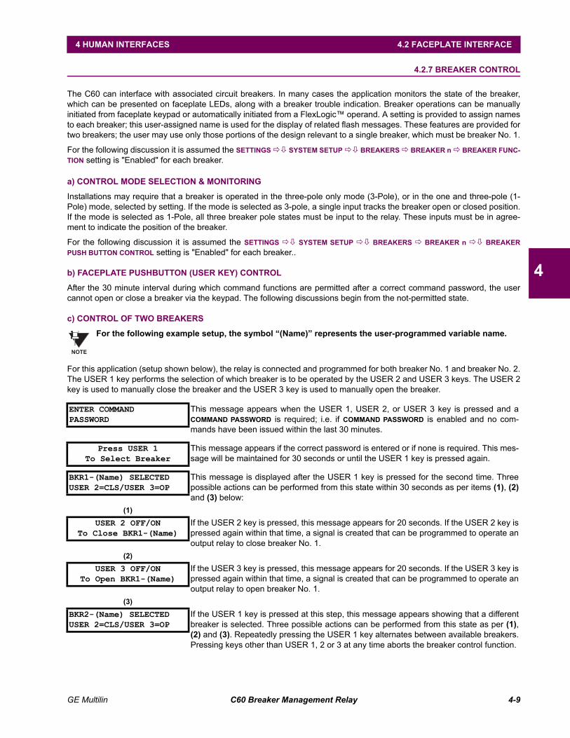
GE Multilin C60 Breaker Management Relay 4-9
4 HUMAN INTERFACES 4.2 FACEPLATE INTERFACE
4
4.2.7 BREAKER CONTROL
The C60 can interface with associated circuit breakers. In many cases the application monitors the state of the breaker,which can be presented on faceplate LEDs, along with a breaker trouble indication. Breaker operations can be manuallyinitiated from faceplate keypad or automatically initiated from a FlexLogic operand. A setting is provided to assign namesto each breaker; this user-assigned name is used for the display of related flash messages. These features are provided fortwo breakers; the user may use only those portions of the design relevant to a single breaker, which must be breaker No. 1.
For the following discussion it is assumed the SETTINGS !" SYSTEM SETUP !" BREAKERS ! BREAKER n ! BREAKER FUNC-TION setting is "Enabled" for each breaker.
a) CONTROL MODE SELECTION & MONITORING
Installations may require that a breaker is operated in the three-pole only mode (3-Pole), or in the one and three-pole (1-Pole) mode, selected by setting. If the mode is selected as 3-pole, a single input tracks the breaker open or closed position.If the mode is selected as 1-Pole, all three breaker pole states must be input to the relay. These inputs must be in agree-ment to indicate the position of the breaker.
For the following discussion it is assumed the SETTINGS !" SYSTEM SETUP !" BREAKERS ! BREAKER n !" BREAKERPUSH BUTTON CONTROL setting is "Enabled" for each breaker..
b) FACEPLATE PUSHBUTTON (USER KEY) CONTROL
After the 30 minute interval during which command functions are permitted after a correct command password, the usercannot open or close a breaker via the keypad. The following discussions begin from the not-permitted state.
c) CONTROL OF TWO BREAKERS
For the following example setup, the symbol (Name) represents the user-programmed variable name.
For this application (setup shown below), the relay is connected and programmed for both breaker No. 1 and breaker No. 2.The USER 1 key performs the selection of which breaker is to be operated by the USER 2 and USER 3 keys. The USER 2key is used to manually close the breaker and the USER 3 key is used to manually open the breaker.
ENTER COMMANDPASSWORD
This message appears when the USER 1, USER 2, or USER 3 key is pressed and aCOMMAND PASSWORD is required; i.e. if COMMAND PASSWORD is enabled and no com-mands have been issued within the last 30 minutes.
Press USER 1To Select Breaker
This message appears if the correct password is entered or if none is required. This mes-sage will be maintained for 30 seconds or until the USER 1 key is pressed again.
BKR1-(Name) SELECTEDUSER 2=CLS/USER 3=OP
This message is displayed after the USER 1 key is pressed for the second time. Threepossible actions can be performed from this state within 30 seconds as per items (1), (2)and (3) below:
(1)USER 2 OFF/ON
To Close BKR1-(Name)If the USER 2 key is pressed, this message appears for 20 seconds. If the USER 2 key ispressed again within that time, a signal is created that can be programmed to operate anoutput relay to close breaker No. 1.
(2)USER 3 OFF/ON
To Open BKR1-(Name)If the USER 3 key is pressed, this message appears for 20 seconds. If the USER 3 key ispressed again within that time, a signal is created that can be programmed to operate anoutput relay to open breaker No. 1.
(3)BKR2-(Name) SELECTEDUSER 2=CLS/USER 3=OP
If the USER 1 key is pressed at this step, this message appears showing that a differentbreaker is selected. Three possible actions can be performed from this state as per (1),(2) and (3). Repeatedly pressing the USER 1 key alternates between available breakers.Pressing keys other than USER 1, 2 or 3 at any time aborts the breaker control function.
NOTE
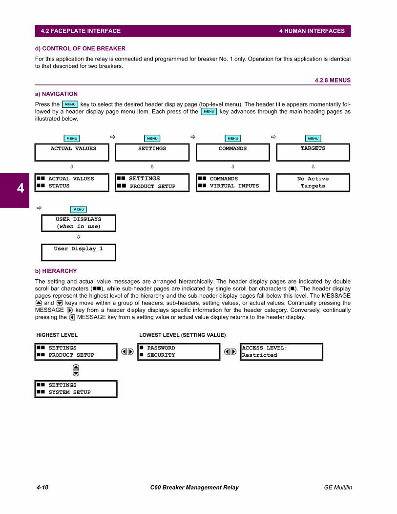
4-10 C60 Breaker Management Relay GE Multilin
4.2 FACEPLATE INTERFACE 4 HUMAN INTERFACES
4
d) CONTROL OF ONE BREAKER
For this application the relay is connected and programmed for breaker No. 1 only. Operation for this application is identicalto that described for two breakers.
4.2.8 MENUS
a) NAVIGATION
Press the key to select the desired header display page (top-level menu). The header title appears momentarily fol-lowed by a header display page menu item. Each press of the key advances through the main heading pages asillustrated below.
b) HIERARCHY
The setting and actual value messages are arranged hierarchically. The header display pages are indicated by doublescroll bar characters (##), while sub-header pages are indicated by single scroll bar characters (#). The header displaypages represent the highest level of the hierarchy and the sub-header display pages fall below this level. The MESSAGE
and keys move within a group of headers, sub-headers, setting values, or actual values. Continually pressing theMESSAGE key from a header display displays specific information for the header category. Conversely, continuallypressing the MESSAGE key from a setting value or actual value display returns to the header display.
! ! !
ACTUAL VALUES SETTINGS COMMANDS TARGETS
" " " "
## ACTUAL VALUES## STATUS
## SETTINGS## PRODUCT SETUP
## COMMANDS## VIRTUAL INPUTS
No ActiveTargets
!
USER DISPLAYS(when in use)
"
User Display 1
HIGHEST LEVEL LOWEST LEVEL (SETTING VALUE)
## SETTINGS## PRODUCT SETUP
# PASSWORD# SECURITY
ACCESS LEVEL:Restricted
## SETTINGS## SYSTEM SETUP
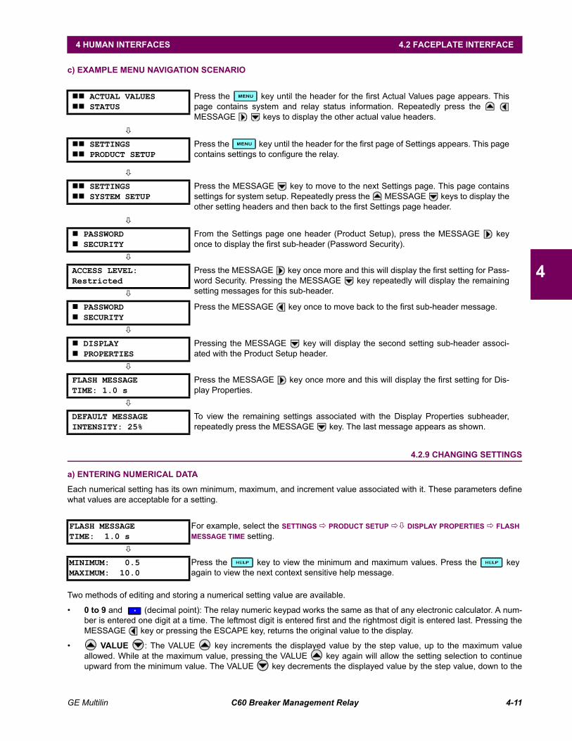
GE Multilin C60 Breaker Management Relay 4-11
4 HUMAN INTERFACES 4.2 FACEPLATE INTERFACE
4
c) EXAMPLE MENU NAVIGATION SCENARIO
4.2.9 CHANGING SETTINGS
a) ENTERING NUMERICAL DATA
Each numerical setting has its own minimum, maximum, and increment value associated with it. These parameters definewhat values are acceptable for a setting.
Two methods of editing and storing a numerical setting value are available.
0 to 9 and (decimal point): The relay numeric keypad works the same as that of any electronic calculator. A num-ber is entered one digit at a time. The leftmost digit is entered first and the rightmost digit is entered last. Pressing theMESSAGE key or pressing the ESCAPE key, returns the original value to the display.
VALUE : The VALUE key increments the displayed value by the step value, up to the maximum valueallowed. While at the maximum value, pressing the VALUE key again will allow the setting selection to continueupward from the minimum value. The VALUE key decrements the displayed value by the step value, down to the
## ACTUAL VALUES## STATUS
Press the key until the header for the first Actual Values page appears. Thispage contains system and relay status information. Repeatedly press the MESSAGE keys to display the other actual value headers.
"
## SETTINGS## PRODUCT SETUP
Press the key until the header for the first page of Settings appears. This pagecontains settings to configure the relay.
"
## SETTINGS## SYSTEM SETUP
Press the MESSAGE key to move to the next Settings page. This page containssettings for system setup. Repeatedly press the MESSAGE keys to display theother setting headers and then back to the first Settings page header.
"
# PASSWORD# SECURITY
From the Settings page one header (Product Setup), press the MESSAGE keyonce to display the first sub-header (Password Security).
"
ACCESS LEVEL:Restricted
Press the MESSAGE key once more and this will display the first setting for Pass-word Security. Pressing the MESSAGE key repeatedly will display the remainingsetting messages for this sub-header."
# PASSWORD# SECURITY
Press the MESSAGE key once to move back to the first sub-header message.
"
# DISPLAY# PROPERTIES
Pressing the MESSAGE key will display the second setting sub-header associ-ated with the Product Setup header.
"
FLASH MESSAGETIME: 1.0 s
Press the MESSAGE key once more and this will display the first setting for Dis-play Properties.
"
DEFAULT MESSAGEINTENSITY: 25%
To view the remaining settings associated with the Display Properties subheader,repeatedly press the MESSAGE key. The last message appears as shown.
FLASH MESSAGETIME: 1.0 s
For example, select the SETTINGS ! PRODUCT SETUP !" DISPLAY PROPERTIES ! FLASHMESSAGE TIME setting.
"
MINIMUM: 0.5MAXIMUM: 10.0
Press the key to view the minimum and maximum values. Press the keyagain to view the next context sensitive help message.
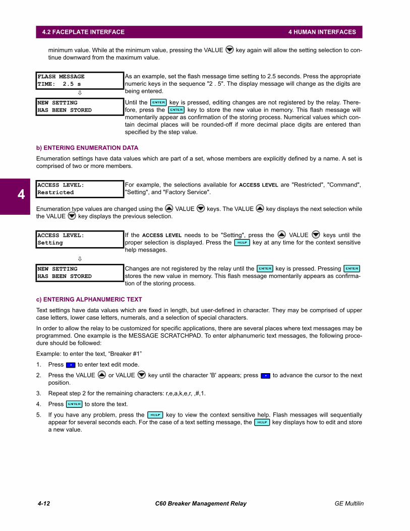
4-12 C60 Breaker Management Relay GE Multilin
4.2 FACEPLATE INTERFACE 4 HUMAN INTERFACES
4
minimum value. While at the minimum value, pressing the VALUE key again will allow the setting selection to con-tinue downward from the maximum value.
b) ENTERING ENUMERATION DATA
Enumeration settings have data values which are part of a set, whose members are explicitly defined by a name. A set iscomprised of two or more members.
Enumeration type values are changed using the VALUE keys. The VALUE key displays the next selection whilethe VALUE key displays the previous selection.
c) ENTERING ALPHANUMERIC TEXT
Text settings have data values which are fixed in length, but user-defined in character. They may be comprised of uppercase letters, lower case letters, numerals, and a selection of special characters.
In order to allow the relay to be customized for specific applications, there are several places where text messages may beprogrammed. One example is the MESSAGE SCRATCHPAD. To enter alphanumeric text messages, the following proce-dure should be followed:
Example: to enter the text, Breaker #1
1. Press to enter text edit mode.
2. Press the VALUE or VALUE key until the character 'B' appears; press to advance the cursor to the nextposition.
3. Repeat step 2 for the remaining characters: r,e,a,k,e,r, ,#,1.
4. Press to store the text.
5. If you have any problem, press the key to view the context sensitive help. Flash messages will sequentiallyappear for several seconds each. For the case of a text setting message, the key displays how to edit and storea new value.
FLASH MESSAGETIME: 2.5 s
As an example, set the flash message time setting to 2.5 seconds. Press the appropriatenumeric keys in the sequence "2 . 5". The display message will change as the digits arebeing entered."
NEW SETTINGHAS BEEN STORED
Until the key is pressed, editing changes are not registered by the relay. There-fore, press the key to store the new value in memory. This flash message willmomentarily appear as confirmation of the storing process. Numerical values which con-tain decimal places will be rounded-off if more decimal place digits are entered thanspecified by the step value.
ACCESS LEVEL:Restricted
For example, the selections available for ACCESS LEVEL are "Restricted", "Command","Setting", and "Factory Service".
ACCESS LEVEL:Setting
If the ACCESS LEVEL needs to be "Setting", press the VALUE keys until theproper selection is displayed. Press the key at any time for the context sensitivehelp messages.
"
NEW SETTINGHAS BEEN STORED
Changes are not registered by the relay until the key is pressed. Pressing stores the new value in memory. This flash message momentarily appears as confirma-tion of the storing process.
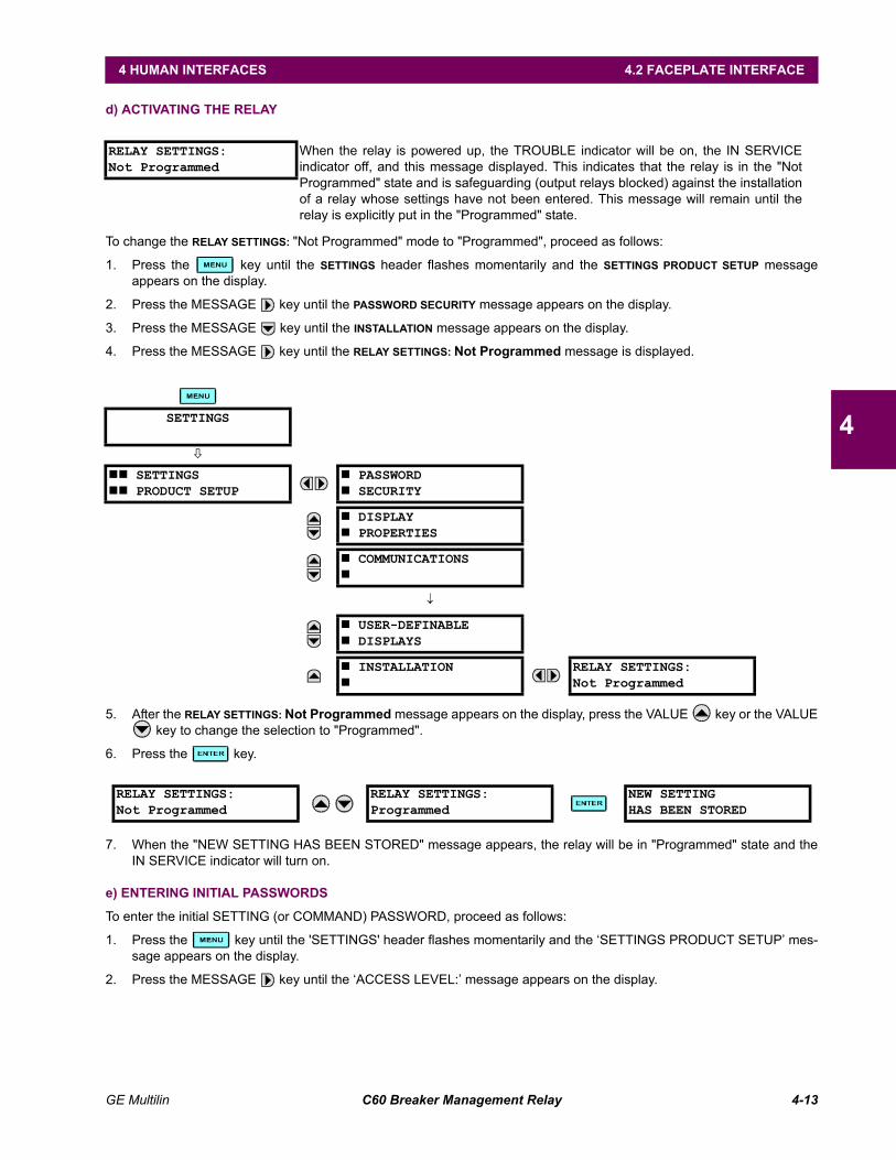
GE Multilin C60 Breaker Management Relay 4-13
4 HUMAN INTERFACES 4.2 FACEPLATE INTERFACE
4
d) ACTIVATING THE RELAY
To change the RELAY SETTINGS: "Not Programmed" mode to "Programmed", proceed as follows:
1. Press the key until the SETTINGS header flashes momentarily and the SETTINGS PRODUCT SETUP messageappears on the display.
2. Press the MESSAGE key until the PASSWORD SECURITY message appears on the display.
3. Press the MESSAGE key until the INSTALLATION message appears on the display.
4. Press the MESSAGE key until the RELAY SETTINGS: Not Programmed message is displayed.
5. After the RELAY SETTINGS: Not Programmed message appears on the display, press the VALUE key or the VALUE key to change the selection to "Programmed".
6. Press the key.
7. When the "NEW SETTING HAS BEEN STORED" message appears, the relay will be in "Programmed" state and theIN SERVICE indicator will turn on.
e) ENTERING INITIAL PASSWORDS
To enter the initial SETTING (or COMMAND) PASSWORD, proceed as follows:
1. Press the key until the 'SETTINGS' header flashes momentarily and the SETTINGS PRODUCT SETUP mes-sage appears on the display.
2. Press the MESSAGE key until the ACCESS LEVEL: message appears on the display.
RELAY SETTINGS:Not Programmed
When the relay is powered up, the TROUBLE indicator will be on, the IN SERVICEindicator off, and this message displayed. This indicates that the relay is in the "NotProgrammed" state and is safeguarding (output relays blocked) against the installationof a relay whose settings have not been entered. This message will remain until therelay is explicitly put in the "Programmed" state.
SETTINGS
"
## SETTINGS## PRODUCT SETUP
# PASSWORD# SECURITY
# DISPLAY# PROPERTIES
# COMMUNICATIONS#
↓
# USER-DEFINABLE# DISPLAYS
# INSTALLATION#
RELAY SETTINGS:Not Programmed
RELAY SETTINGS:Not Programmed
RELAY SETTINGS:Programmed
NEW SETTINGHAS BEEN STORED
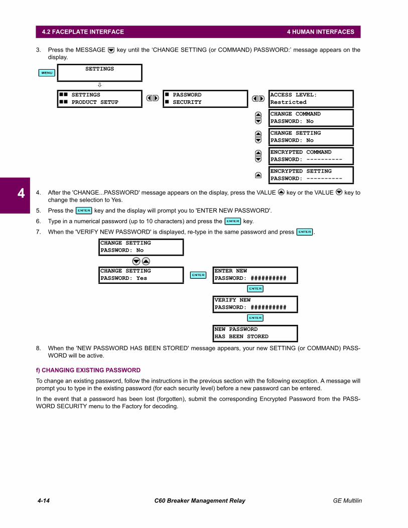
4-14 C60 Breaker Management Relay GE Multilin
4.2 FACEPLATE INTERFACE 4 HUMAN INTERFACES
4
3. Press the MESSAGE key until the CHANGE SETTING (or COMMAND) PASSWORD: message appears on thedisplay.
4. After the 'CHANGE...PASSWORD' message appears on the display, press the VALUE key or the VALUE key tochange the selection to Yes.
5. Press the key and the display will prompt you to 'ENTER NEW PASSWORD'.
6. Type in a numerical password (up to 10 characters) and press the key.
7. When the 'VERIFY NEW PASSWORD' is displayed, re-type in the same password and press .
8. When the 'NEW PASSWORD HAS BEEN STORED' message appears, your new SETTING (or COMMAND) PASS-WORD will be active.
f) CHANGING EXISTING PASSWORD
To change an existing password, follow the instructions in the previous section with the following exception. A message willprompt you to type in the existing password (for each security level) before a new password can be entered.
In the event that a password has been lost (forgotten), submit the corresponding Encrypted Password from the PASS-WORD SECURITY menu to the Factory for decoding.
SETTINGS
"
## SETTINGS## PRODUCT SETUP
# PASSWORD# SECURITY
ACCESS LEVEL:Restricted
CHANGE COMMANDPASSWORD: No
CHANGE SETTINGPASSWORD: No
ENCRYPTED COMMANDPASSWORD: ----------
ENCRYPTED SETTINGPASSWORD: ----------
CHANGE SETTINGPASSWORD: No
CHANGE SETTINGPASSWORD: Yes
ENTER NEWPASSWORD: ##########
VERIFY NEWPASSWORD: ##########
NEW PASSWORDHAS BEEN STORED
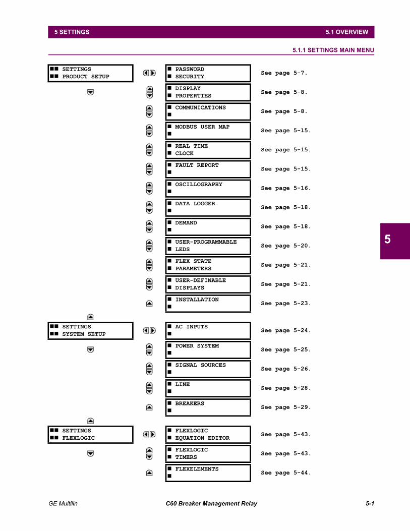
GE Multilin C60 Breaker Management Relay 5-1
5 SETTINGS 5.1 OVERVIEW
5
5 SETTINGS 5.1 OVERVIEW 5.1.1 SETTINGS MAIN MENU
## SETTINGS## PRODUCT SETUP
# PASSWORD# SECURITY
See page 5-7.
# DISPLAY# PROPERTIES
See page 5-8.
# COMMUNICATIONS#
See page 5-8.
# MODBUS USER MAP#
See page 5-15.
# REAL TIME# CLOCK
See page 5-15.
# FAULT REPORT#
See page 5-15.
# OSCILLOGRAPHY#
See page 5-16.
# DATA LOGGER#
See page 5-18.
# DEMAND#
See page 5-18.
# USER-PROGRAMMABLE# LEDS
See page 5-20.
# FLEX STATE# PARAMETERS
See page 5-21.
# USER-DEFINABLE# DISPLAYS
See page 5-21.
# INSTALLATION#
See page 5-23.
## SETTINGS## SYSTEM SETUP
# AC INPUTS#
See page 5-24.
# POWER SYSTEM#
See page 5-25.
# SIGNAL SOURCES#
See page 5-26.
# LINE#
See page 5-28.
# BREAKERS#
See page 5-29.
## SETTINGS## FLEXLOGIC
# FLEXLOGIC# EQUATION EDITOR
See page 5-43.
# FLEXLOGIC# TIMERS
See page 5-43.
# FLEXELEMENTS#
See page 5-44.
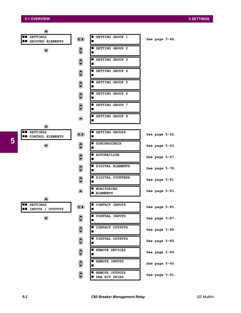
5-2 C60 Breaker Management Relay GE Multilin
5.1 OVERVIEW 5 SETTINGS
5
## SETTINGS## GROUPED ELEMENTS
# SETTING GROUP 1#
See page 5-48.
# SETTING GROUP 2#
# SETTING GROUP 3#
# SETTING GROUP 4#
# SETTING GROUP 5#
# SETTING GROUP 6#
# SETTING GROUP 7#
# SETTING GROUP 8#
## SETTINGS## CONTROL ELEMENTS
# SETTING GROUPS#
See page 5-62.
# SYNCHROCHECK#
See page 5-63.
# AUTORECLOSE#
See page 5-67.
# DIGITAL ELEMENTS#
See page 5-78.
# DIGITAL COUNTERS#
See page 5-81.
# MONITORING# ELEMENTS
See page 5-83.
## SETTINGS## INPUTS / OUTPUTS
# CONTACT INPUTS#
See page 5-85.
# VIRTUAL INPUTS#
See page 5-87.
# CONTACT OUTPUTS#
See page 5-88.
# VIRTUAL OUTPUTS#
See page 5-89.
# REMOTE DEVICES#
See page 5-89.
# REMOTE INPUTS#
See page 5-90.
# REMOTE OUTPUTS# DNA BIT PAIRS
See page 5-91.
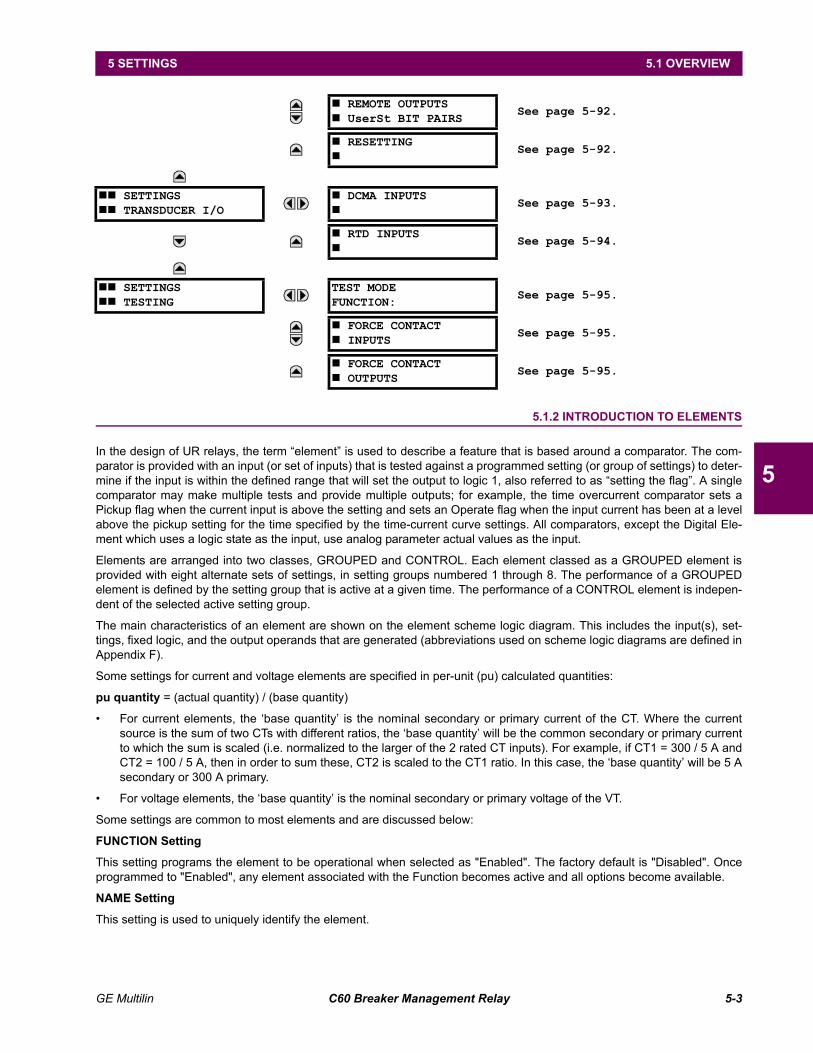
GE Multilin C60 Breaker Management Relay 5-3
5 SETTINGS 5.1 OVERVIEW
5
5.1.2 INTRODUCTION TO ELEMENTS
In the design of UR relays, the term element is used to describe a feature that is based around a comparator. The com-parator is provided with an input (or set of inputs) that is tested against a programmed setting (or group of settings) to deter-mine if the input is within the defined range that will set the output to logic 1, also referred to as setting the flag. A singlecomparator may make multiple tests and provide multiple outputs; for example, the time overcurrent comparator sets aPickup flag when the current input is above the setting and sets an Operate flag when the input current has been at a levelabove the pickup setting for the time specified by the time-current curve settings. All comparators, except the Digital Ele-ment which uses a logic state as the input, use analog parameter actual values as the input.
Elements are arranged into two classes, GROUPED and CONTROL. Each element classed as a GROUPED element isprovided with eight alternate sets of settings, in setting groups numbered 1 through 8. The performance of a GROUPEDelement is defined by the setting group that is active at a given time. The performance of a CONTROL element is indepen-dent of the selected active setting group.
The main characteristics of an element are shown on the element scheme logic diagram. This includes the input(s), set-tings, fixed logic, and the output operands that are generated (abbreviations used on scheme logic diagrams are defined inAppendix F).
Some settings for current and voltage elements are specified in per-unit (pu) calculated quantities:
pu quantity = (actual quantity) / (base quantity)
For current elements, the base quantity is the nominal secondary or primary current of the CT. Where the currentsource is the sum of two CTs with different ratios, the base quantity will be the common secondary or primary currentto which the sum is scaled (i.e. normalized to the larger of the 2 rated CT inputs). For example, if CT1 = 300 / 5 A andCT2 = 100 / 5 A, then in order to sum these, CT2 is scaled to the CT1 ratio. In this case, the base quantity will be 5 Asecondary or 300 A primary.
For voltage elements, the base quantity is the nominal secondary or primary voltage of the VT.
Some settings are common to most elements and are discussed below:
FUNCTION Setting
This setting programs the element to be operational when selected as "Enabled". The factory default is "Disabled". Onceprogrammed to "Enabled", any element associated with the Function becomes active and all options become available.
NAME Setting
This setting is used to uniquely identify the element.
# REMOTE OUTPUTS# UserSt BIT PAIRS
See page 5-92.
# RESETTING#
See page 5-92.
## SETTINGS## TRANSDUCER I/O
# DCMA INPUTS#
See page 5-93.
# RTD INPUTS#
See page 5-94.
## SETTINGS## TESTING
TEST MODEFUNCTION:
See page 5-95.
# FORCE CONTACT# INPUTS
See page 5-95.
# FORCE CONTACT# OUTPUTS
See page 5-95.

5-4 C60 Breaker Management Relay GE Multilin
5.1 OVERVIEW 5 SETTINGS
5
SOURCE Setting
This setting is used to select the parameter or set of parameters to be monitored.
PICKUP Setting
For simple elements, this setting is used to program the level of the measured parameter above or below which the pickupstate is established. In more complex elements, a set of settings may be provided to define the range of the measuredparameters which will cause the element to pickup.
PICKUP DELAY Setting
This setting sets a time-delay-on-pickup, or on-delay, for the duration between the Pickup and Operate output states.
RESET DELAY Setting
This setting is used to set a time-delay-on-dropout, or off-delay, for the duration between the Operate output state and thereturn to logic 0 after the input transits outside the defined pickup range.
BLOCK Setting
The default output operand state of all comparators is a logic 0 or flag not set. The comparator remains in this defaultstate until a logic 1 is asserted at the RUN input, allowing the test to be performed. If the RUN input changes to logic 0 atany time, the comparator returns to the default state. The RUN input is used to supervise the comparator. The BLOCK inputis used as one of the inputs to RUN control.
TARGET Setting
This setting is used to define the operation of an element target message. When set to Disabled, no target message or illu-mination of a faceplate LED indicator is issued upon operation of the element. When set to Self-Reset, the target messageand LED indication follow the Operate state of the element, and self-resets once the operate element condition clears.When set to Latched, the target message and LED indication will remain visible after the element output returns to logic 0 -until a RESET command is received by the relay.
EVENTS Setting
This setting is used to control whether the Pickup, Dropout or Operate states are recorded by the event recorder. When setto Disabled, element pickup, dropout or operate are not recorded as events.
When set to Enabled, an event is created for:
(Element) PKP (pickup)
(Element) DPO (dropout)
(Element) OP (operate)
The DPO event is created when the measure and decide comparator output transits from the pickup state (logic 1) to thedropout state (logic 0). This could happen when the element is in the operate state if the reset delay time is not 0.
5.1.3 INTRODUCTION TO AC SOURCES
a) BACKGROUND
The C60 may be used on systems with breaker-and-a-half or ring bus configurations. In these applications, each of the twothree-phase sets of individual phase currents (one associated with each breaker) can be used as an input to a breaker fail-ure element. The sum of both breaker phase currents and 3I_0 residual currents may be required for the circuit relayingand metering functions. For a three-winding transformer application, it may be required to calculate watts and vars for eachof three windings, using voltage from different sets of VTs. All these requirements can be satisfied with a single UR relay,equipped with sufficient CT and VT input channels, by selecting the parameter to be measured. A mechanism is providedto specify the AC parameter (or group of parameters) used as the input to protection/control comparators and some meter-ing elements.
Selection of the parameter(s) to be measured is partially performed by the design of a measuring element or protection/control comparator, by identifying the type of parameter (fundamental frequency phasor, harmonic phasor, symmetricalcomponent, total waveform RMS magnitude, phase-phase or phase-ground voltage, etc.) to be measured. The user com-pletes the selection process by selecting the instrument transformer input channels to be used and some of the parameterscalculated from these channels. The input parameters available include the summation of currents from multiple inputchannels. For the summed currents of phase, 3I_0 and ground current, current from CTs with different ratios are adjusted toa single ratio before the summation.
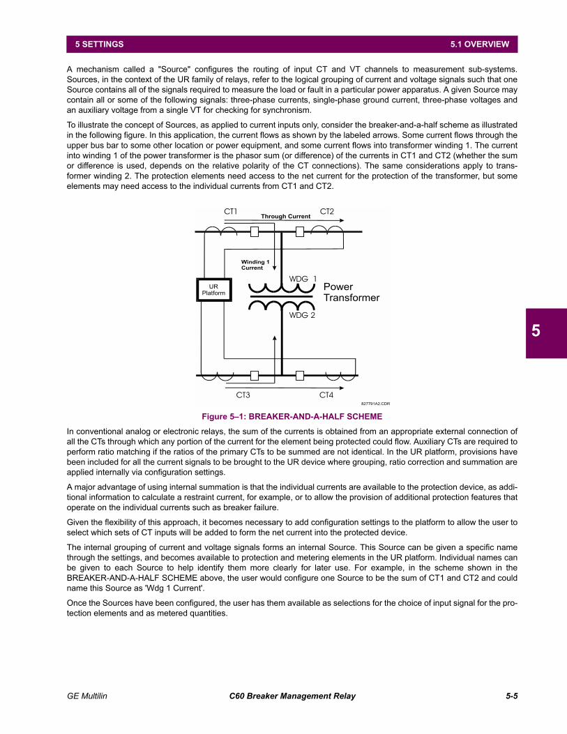
GE Multilin C60 Breaker Management Relay 5-5
5 SETTINGS 5.1 OVERVIEW
5
A mechanism called a "Source" configures the routing of input CT and VT channels to measurement sub-systems.Sources, in the context of the UR family of relays, refer to the logical grouping of current and voltage signals such that oneSource contains all of the signals required to measure the load or fault in a particular power apparatus. A given Source maycontain all or some of the following signals: three-phase currents, single-phase ground current, three-phase voltages andan auxiliary voltage from a single VT for checking for synchronism.
To illustrate the concept of Sources, as applied to current inputs only, consider the breaker-and-a-half scheme as illustratedin the following figure. In this application, the current flows as shown by the labeled arrows. Some current flows through theupper bus bar to some other location or power equipment, and some current flows into transformer winding 1. The currentinto winding 1 of the power transformer is the phasor sum (or difference) of the currents in CT1 and CT2 (whether the sumor difference is used, depends on the relative polarity of the CT connections). The same considerations apply to trans-former winding 2. The protection elements need access to the net current for the protection of the transformer, but someelements may need access to the individual currents from CT1 and CT2.
Figure 51: BREAKER-AND-A-HALF SCHEME
In conventional analog or electronic relays, the sum of the currents is obtained from an appropriate external connection ofall the CTs through which any portion of the current for the element being protected could flow. Auxiliary CTs are required toperform ratio matching if the ratios of the primary CTs to be summed are not identical. In the UR platform, provisions havebeen included for all the current signals to be brought to the UR device where grouping, ratio correction and summation areapplied internally via configuration settings.
A major advantage of using internal summation is that the individual currents are available to the protection device, as addi-tional information to calculate a restraint current, for example, or to allow the provision of additional protection features thatoperate on the individual currents such as breaker failure.
Given the flexibility of this approach, it becomes necessary to add configuration settings to the platform to allow the user toselect which sets of CT inputs will be added to form the net current into the protected device.
The internal grouping of current and voltage signals forms an internal Source. This Source can be given a specific namethrough the settings, and becomes available to protection and metering elements in the UR platform. Individual names canbe given to each Source to help identify them more clearly for later use. For example, in the scheme shown in theBREAKER-AND-A-HALF SCHEME above, the user would configure one Source to be the sum of CT1 and CT2 and couldname this Source as 'Wdg 1 Current'.
Once the Sources have been configured, the user has them available as selections for the choice of input signal for the pro-tection elements and as metered quantities.
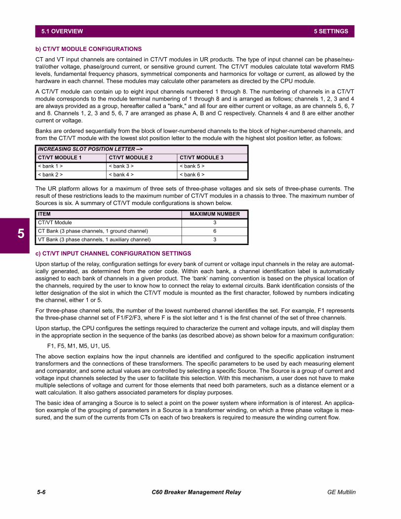
5-6 C60 Breaker Management Relay GE Multilin
5.1 OVERVIEW 5 SETTINGS
5
b) CT/VT MODULE CONFIGURATIONS
CT and VT input channels are contained in CT/VT modules in UR products. The type of input channel can be phase/neu-tral/other voltage, phase/ground current, or sensitive ground current. The CT/VT modules calculate total waveform RMSlevels, fundamental frequency phasors, symmetrical components and harmonics for voltage or current, as allowed by thehardware in each channel. These modules may calculate other parameters as directed by the CPU module.
A CT/VT module can contain up to eight input channels numbered 1 through 8. The numbering of channels in a CT/VTmodule corresponds to the module terminal numbering of 1 through 8 and is arranged as follows; channels 1, 2, 3 and 4are always provided as a group, hereafter called a "bank," and all four are either current or voltage, as are channels 5, 6, 7and 8. Channels 1, 2, 3 and 5, 6, 7 are arranged as phase A, B and C respectively. Channels 4 and 8 are either anothercurrent or voltage.
Banks are ordered sequentially from the block of lower-numbered channels to the block of higher-numbered channels, andfrom the CT/VT module with the lowest slot position letter to the module with the highest slot position letter, as follows:
The UR platform allows for a maximum of three sets of three-phase voltages and six sets of three-phase currents. Theresult of these restrictions leads to the maximum number of CT/VT modules in a chassis to three. The maximum number ofSources is six. A summary of CT/VT module configurations is shown below.
c) CT/VT INPUT CHANNEL CONFIGURATION SETTINGS
Upon startup of the relay, configuration settings for every bank of current or voltage input channels in the relay are automat-ically generated, as determined from the order code. Within each bank, a channel identification label is automaticallyassigned to each bank of channels in a given product. The bank naming convention is based on the physical location ofthe channels, required by the user to know how to connect the relay to external circuits. Bank identification consists of theletter designation of the slot in which the CT/VT module is mounted as the first character, followed by numbers indicatingthe channel, either 1 or 5.
For three-phase channel sets, the number of the lowest numbered channel identifies the set. For example, F1 representsthe three-phase channel set of F1/F2/F3, where F is the slot letter and 1 is the first channel of the set of three channels.
Upon startup, the CPU configures the settings required to characterize the current and voltage inputs, and will display themin the appropriate section in the sequence of the banks (as described above) as shown below for a maximum configuration:
F1, F5, M1, M5, U1, U5.
The above section explains how the input channels are identified and configured to the specific application instrumenttransformers and the connections of these transformers. The specific parameters to be used by each measuring elementand comparator, and some actual values are controlled by selecting a specific Source. The Source is a group of current andvoltage input channels selected by the user to facilitate this selection. With this mechanism, a user does not have to makemultiple selections of voltage and current for those elements that need both parameters, such as a distance element or awatt calculation. It also gathers associated parameters for display purposes.
The basic idea of arranging a Source is to select a point on the power system where information is of interest. An applica-tion example of the grouping of parameters in a Source is a transformer winding, on which a three phase voltage is mea-sured, and the sum of the currents from CTs on each of two breakers is required to measure the winding current flow.
INCREASING SLOT POSITION LETTER -->CT/VT MODULE 1 CT/VT MODULE 2 CT/VT MODULE 3< bank 1 > < bank 3 > < bank 5 >< bank 2 > < bank 4 > < bank 6 >
ITEM MAXIMUM NUMBERCT/VT Module 3CT Bank (3 phase channels, 1 ground channel) 6VT Bank (3 phase channels, 1 auxiliary channel) 3

GE Multilin C60 Breaker Management Relay 5-7
5 SETTINGS 5.2 PRODUCT SETUP
5
5.2 PRODUCT SETUP 5.2.1 PASSWORD SECURITY
PATH: SETTINGS ! PRODUCT SETUP ! PASSWORD SECURITY
The UR provides two user levels of password security: Command and Setting. Operations under password supervision areas follows:
COMMAND:
Operating the breakers via faceplate keypad
Changing the state of virtual inputs
Clearing the event records
Clearing the oscillography records
SETTING:
Changing any setting.
The Command and Setting passwords are defaulted to "Null" when the relay is shipped from the factory. When a passwordis set to "Null", the password security feature is disabled.
Programming a password code is required to enable each access level. A password consists of 1 to 10 numerical charac-ters. When a CHANGE ... PASSWORD setting is set to "Yes", the following message sequence is invoked:
1. ENTER NEW PASSWORD: ____________
2. VERIFY NEW PASSWORD: ____________
3. NEW PASSWORD HAS BEEN STORED
To gain write access to a "Restricted" setting, set ACCESS LEVEL to "Setting" and then change the setting, or attempt tochange the setting and follow the prompt to enter the programmed password. If the password is correctly entered, accesswill be allowed. If no keys are pressed for longer than 30 minutes or control power is cycled, accessibility will automaticallyrevert to the "Restricted" level.
If an entered password is lost (or forgotten), consult the factory service department with the corresponding ENCRYPTEDPASSWORD.
If the SETTING password and COMMAND password are set the same, the one password will allow access tocommands and settings.
# PASSWORD# SECURITY
ACCESS LEVEL:Restricted
Range: Restricted, Command, Setting, Factory Service (for factory use only)
MESSAGECHANGE COMMANDPASSWORD: No
Range: No, Yes
MESSAGECHANGE SETTINGPASSWORD: No
Range: No, Yes
MESSAGEENCRYPTED COMMANDPASSWORD: ----------
Range: 0 to 9999999999Note: ---------- indicates no password
MESSAGEENCRYPTED SETTINGPASSWORD: ----------
Range: 0 to 9999999999Note: ---------- indicates no password
NOTE

5-8 C60 Breaker Management Relay GE Multilin
5.2 PRODUCT SETUP 5 SETTINGS
5
5.2.2 DISPLAY PROPERTIES
PATH: SETTINGS ! PRODUCT SETUP !" DISPLAY PROPERTIES
Some relay messaging characteristics can be modified to suit different situations using the display properties settings.
Flash messages are status, warning, error, or information messages displayed for several seconds in response to certainkey presses during setting programming. These messages override any normal messages. The time a flash messageremains on the display can be changed to accommodate different reading rates. If no keys are pressed for a period of time,the relay automatically displays a default message. This time can be modified to ensure messages remain on the screenlong enough during programming or reading of actual values.
To extend the life of the phosphor in the vacuum fluorescent display, the brightness can be attenuated when displayingdefault messages. When interacting with the display using the keypad, the display always operates at full brightness.
5.2.3 COMMUNICATIONS
a) SERIAL PORTS
PATH: SETTINGS ! PRODUCT SETUP !" COMMUNICATIONS ! SERIAL PORTS
The C60 is equipped with up to 3 independent serial communication ports. The faceplate RS232 port is intended for localuse and has fixed parameters of 19200 baud and no parity. The rear COM1 port type will depend on the CPU ordered: itmay be either an Ethernet or an RS485 port. The rear COM2 port is RS485. The RS485 ports have settings for baud rateand parity. It is important that these parameters agree with the settings used on the computer or other equipment that isconnected to these ports. Any of these ports may be connected to a personal computer running URPC. This software isused for downloading or uploading setting files, viewing measured parameters, and upgrading the relay firmware to the lat-est version. A maximum of 32 relays can be daisy-chained and connected to a DCS, PLC or PC using the RS485 ports.
For each RS485 port, the minimum time before the port will transmit after receiving data from a host can beset. This feature allows operation with hosts which hold the RS485 transmitter active for some time aftereach transmission.
# DISPLAY# PROPERTIES
FLASH MESSAGETIME: 1.0 s
Range: 0.5 to 10.0 s in steps of 0.1
MESSAGEDEFAULT MESSAGETIMEOUT: 300 s
Range: 10 to 900 s in steps of 1
MESSAGEDEFAULT MESSAGEINTENSITY: 25 %
Range: 25%, 50%, 75%, 100%
# COMMUNICATIONS#
# SERIAL PORTS#
MESSAGERS485 COM1 BAUDRATE: 19200
Range: 300, 1200, 2400, 4800, 9600, 14400, 19200, 28800, 33600,38400, 57600, 115200. Only active if CPU 9A is ordered.
MESSAGERS485 COM1 PARITY:None
Range: None, Odd, EvenOnly active if CPU Type 9A is ordered
MESSAGERS485 COM1 RESPONSEMIN TIME: 0 ms
Range: 0 to 1000 ms in steps of 10Only active if CPU Type 9A is ordered
MESSAGERS485 COM2 BAUDRATE: 19200
Range: 300, 1200, 2400, 4800, 9600, 14400, 19200, 28800, 33600,38400, 57600, 115200
MESSAGERS485 COM2 PARITY:None
Range: None, Odd, Even
MESSAGERS485 COM2 RESPONSEMIN TIME: 0 ms
Range: 0 to 1000 ms in steps of 10
NOTE
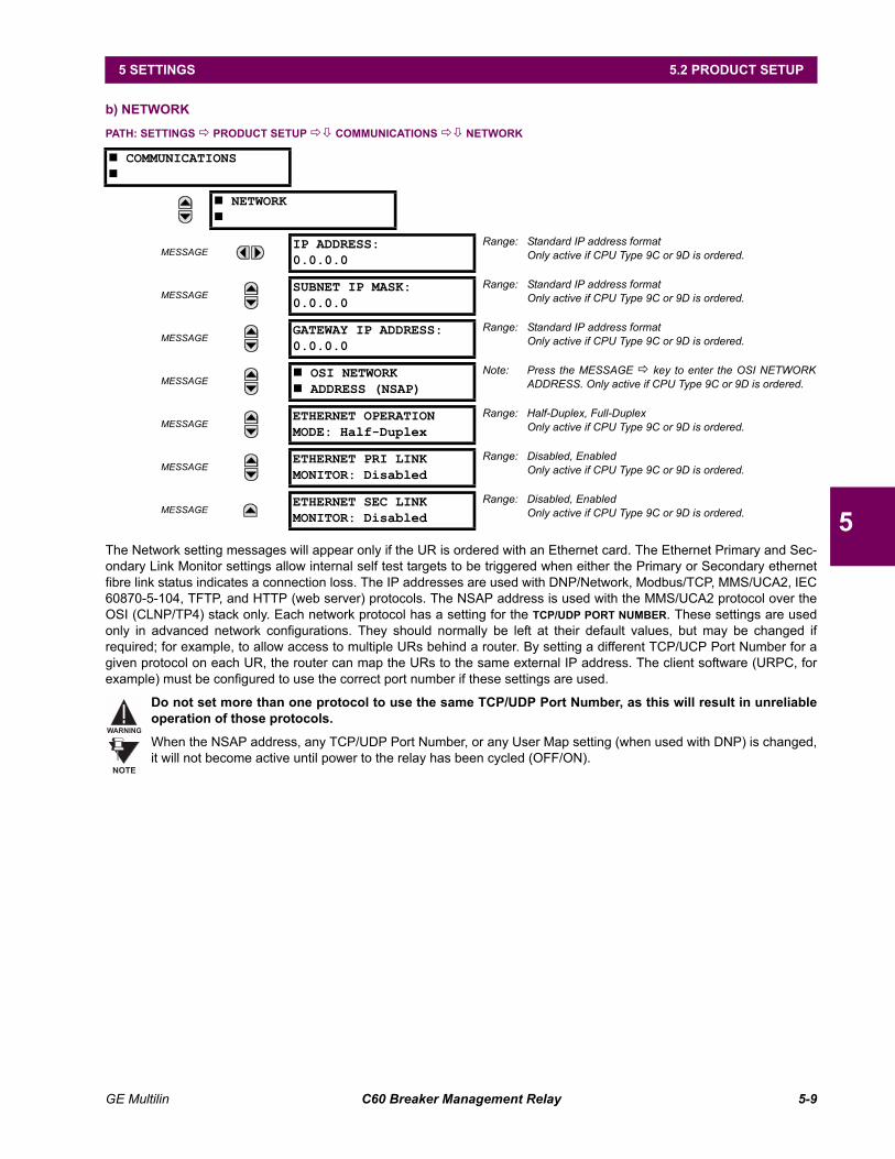
GE Multilin C60 Breaker Management Relay 5-9
5 SETTINGS 5.2 PRODUCT SETUP
5
b) NETWORK
PATH: SETTINGS ! PRODUCT SETUP !" COMMUNICATIONS !" NETWORK
The Network setting messages will appear only if the UR is ordered with an Ethernet card. The Ethernet Primary and Sec-ondary Link Monitor settings allow internal self test targets to be triggered when either the Primary or Secondary ethernetfibre link status indicates a connection loss. The IP addresses are used with DNP/Network, Modbus/TCP, MMS/UCA2, IEC60870-5-104, TFTP, and HTTP (web server) protocols. The NSAP address is used with the MMS/UCA2 protocol over theOSI (CLNP/TP4) stack only. Each network protocol has a setting for the TCP/UDP PORT NUMBER. These settings are usedonly in advanced network configurations. They should normally be left at their default values, but may be changed ifrequired; for example, to allow access to multiple URs behind a router. By setting a different TCP/UCP Port Number for agiven protocol on each UR, the router can map the URs to the same external IP address. The client software (URPC, forexample) must be configured to use the correct port number if these settings are used.
Do not set more than one protocol to use the same TCP/UDP Port Number, as this will result in unreliableoperation of those protocols.
When the NSAP address, any TCP/UDP Port Number, or any User Map setting (when used with DNP) is changed,it will not become active until power to the relay has been cycled (OFF/ON).
# COMMUNICATIONS#
# NETWORK#
MESSAGEIP ADDRESS:0.0.0.0
Range: Standard IP address formatOnly active if CPU Type 9C or 9D is ordered.
MESSAGESUBNET IP MASK:0.0.0.0
Range: Standard IP address formatOnly active if CPU Type 9C or 9D is ordered.
MESSAGEGATEWAY IP ADDRESS:0.0.0.0
Range: Standard IP address formatOnly active if CPU Type 9C or 9D is ordered.
MESSAGE# OSI NETWORK# ADDRESS (NSAP)
Note: Press the MESSAGE ! key to enter the OSI NETWORKADDRESS. Only active if CPU Type 9C or 9D is ordered.
MESSAGEETHERNET OPERATIONMODE: Half-Duplex
Range: Half-Duplex, Full-DuplexOnly active if CPU Type 9C or 9D is ordered.
MESSAGEETHERNET PRI LINKMONITOR: Disabled
Range: Disabled, EnabledOnly active if CPU Type 9C or 9D is ordered.
MESSAGEETHERNET SEC LINKMONITOR: Disabled
Range: Disabled, EnabledOnly active if CPU Type 9C or 9D is ordered.
WARNING
NOTE
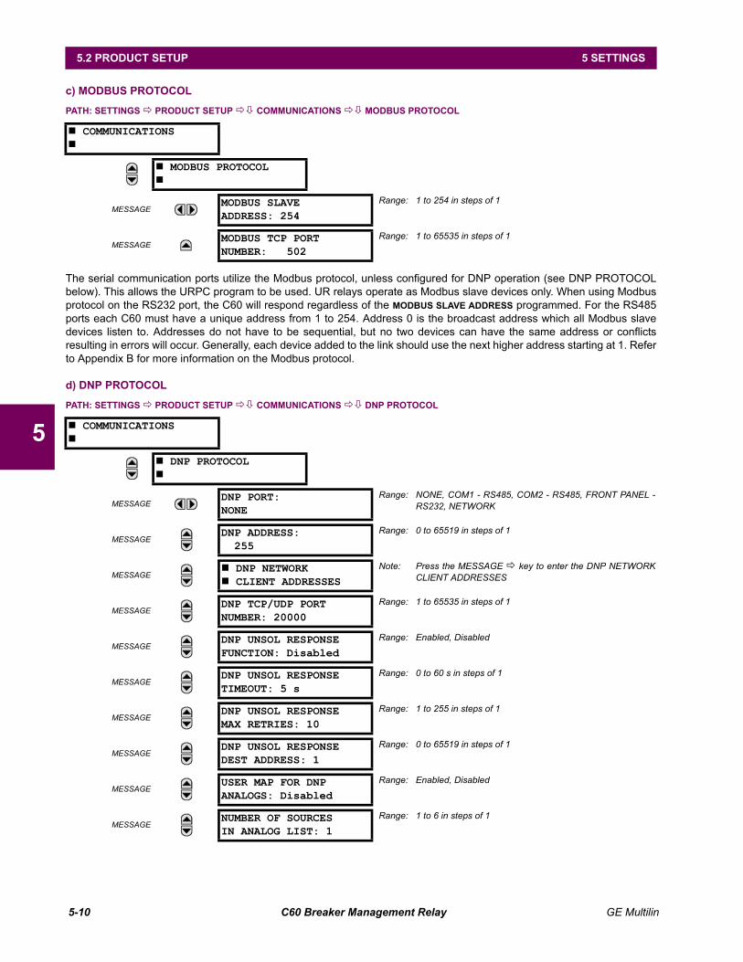
5-10 C60 Breaker Management Relay GE Multilin
5.2 PRODUCT SETUP 5 SETTINGS
5
c) MODBUS PROTOCOL
PATH: SETTINGS ! PRODUCT SETUP !" COMMUNICATIONS !" MODBUS PROTOCOL
The serial communication ports utilize the Modbus protocol, unless configured for DNP operation (see DNP PROTOCOLbelow). This allows the URPC program to be used. UR relays operate as Modbus slave devices only. When using Modbusprotocol on the RS232 port, the C60 will respond regardless of the MODBUS SLAVE ADDRESS programmed. For the RS485ports each C60 must have a unique address from 1 to 254. Address 0 is the broadcast address which all Modbus slavedevices listen to. Addresses do not have to be sequential, but no two devices can have the same address or conflictsresulting in errors will occur. Generally, each device added to the link should use the next higher address starting at 1. Referto Appendix B for more information on the Modbus protocol.
d) DNP PROTOCOL
PATH: SETTINGS ! PRODUCT SETUP !" COMMUNICATIONS !" DNP PROTOCOL
# COMMUNICATIONS#
# MODBUS PROTOCOL#
MESSAGEMODBUS SLAVEADDRESS: 254
Range: 1 to 254 in steps of 1
MESSAGEMODBUS TCP PORTNUMBER: 502
Range: 1 to 65535 in steps of 1
# COMMUNICATIONS#
# DNP PROTOCOL#
MESSAGEDNP PORT:NONE
Range: NONE, COM1 - RS485, COM2 - RS485, FRONT PANEL -RS232, NETWORK
MESSAGEDNP ADDRESS:
255Range: 0 to 65519 in steps of 1
MESSAGE# DNP NETWORK# CLIENT ADDRESSES
Note: Press the MESSAGE ! key to enter the DNP NETWORKCLIENT ADDRESSES
MESSAGEDNP TCP/UDP PORTNUMBER: 20000
Range: 1 to 65535 in steps of 1
MESSAGEDNP UNSOL RESPONSEFUNCTION: Disabled
Range: Enabled, Disabled
MESSAGEDNP UNSOL RESPONSETIMEOUT: 5 s
Range: 0 to 60 s in steps of 1
MESSAGEDNP UNSOL RESPONSEMAX RETRIES: 10
Range: 1 to 255 in steps of 1
MESSAGEDNP UNSOL RESPONSEDEST ADDRESS: 1
Range: 0 to 65519 in steps of 1
MESSAGEUSER MAP FOR DNPANALOGS: Disabled
Range: Enabled, Disabled
MESSAGENUMBER OF SOURCESIN ANALOG LIST: 1
Range: 1 to 6 in steps of 1
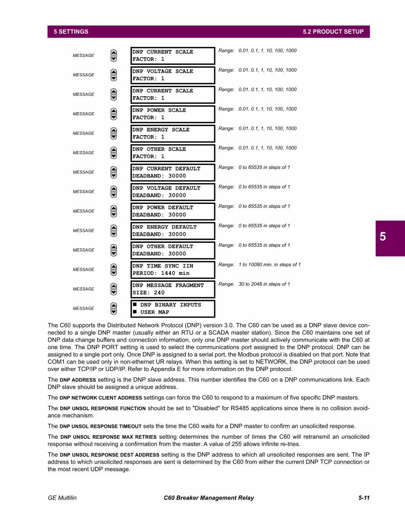
GE Multilin C60 Breaker Management Relay 5-11
5 SETTINGS 5.2 PRODUCT SETUP
5
The C60 supports the Distributed Network Protocol (DNP) version 3.0. The C60 can be used as a DNP slave device con-nected to a single DNP master (usually either an RTU or a SCADA master station). Since the C60 maintains one set ofDNP data change buffers and connection information, only one DNP master should actively communicate with the C60 atone time. The DNP PORT setting is used to select the communications port assigned to the DNP protocol. DNP can beassigned to a single port only. Once DNP is assigned to a serial port, the Modbus protocol is disabled on that port. Note thatCOM1 can be used only in non-ethernet UR relays. When this setting is set to NETWORK, the DNP protocol can be usedover either TCP/IP or UDP/IP. Refer to Appendix E for more information on the DNP protocol.
The DNP ADDRESS setting is the DNP slave address. This number identifies the C60 on a DNP communications link. EachDNP slave should be assigned a unique address.
The DNP NETWORK CLIENT ADDRESS settings can force the C60 to respond to a maximum of five specific DNP masters.
The DNP UNSOL RESPONSE FUNCTION should be set to "Disabled" for RS485 applications since there is no collision avoid-ance mechanism.
The DNP UNSOL RESPONSE TIMEOUT sets the time the C60 waits for a DNP master to confirm an unsolicited response.
The DNP UNSOL RESPONSE MAX RETRIES setting determines the number of times the C60 will retransmit an unsolicitedresponse without receiving a confirmation from the master. A value of 255 allows infinite re-tries.
The DNP UNSOL RESPONSE DEST ADDRESS setting is the DNP address to which all unsolicited responses are sent. The IPaddress to which unsolicited responses are sent is determined by the C60 from either the current DNP TCP connection orthe most recent UDP message.
MESSAGEDNP CURRENT SCALEFACTOR: 1
Range: 0.01. 0.1, 1, 10, 100, 1000
MESSAGEDNP VOLTAGE SCALEFACTOR: 1
Range: 0.01. 0.1, 1, 10, 100, 1000
MESSAGEDNP CURRENT SCALEFACTOR: 1
Range: 0.01. 0.1, 1, 10, 100, 1000
MESSAGEDNP POWER SCALEFACTOR: 1
Range: 0.01. 0.1, 1, 10, 100, 1000
MESSAGEDNP ENERGY SCALEFACTOR: 1
Range: 0.01. 0.1, 1, 10, 100, 1000
MESSAGEDNP OTHER SCALEFACTOR: 1
Range: 0.01. 0.1, 1, 10, 100, 1000
MESSAGEDNP CURRENT DEFAULTDEADBAND: 30000
Range: 0 to 65535 in steps of 1
MESSAGEDNP VOLTAGE DEFAULTDEADBAND: 30000
Range: 0 to 65535 in steps of 1
MESSAGEDNP POWER DEFAULTDEADBAND: 30000
Range: 0 to 65535 in steps of 1
MESSAGEDNP ENERGY DEFAULTDEADBAND: 30000
Range: 0 to 65535 in steps of 1
MESSAGEDNP OTHER DEFAULTDEADBAND: 30000
Range: 0 to 65535 in steps of 1
MESSAGEDNP TIME SYNC IINPERIOD: 1440 min
Range: 1 to 10080 min. in steps of 1
MESSAGEDNP MESSAGE FRAGMENTSIZE: 240
Range: 30 to 2048 in steps of 1
MESSAGE# DNP BINARY INPUTS# USER MAP
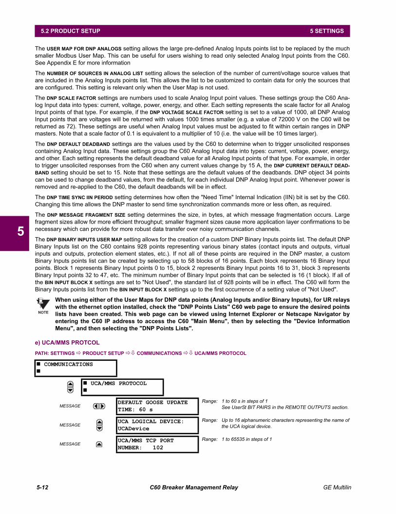
5-12 C60 Breaker Management Relay GE Multilin
5.2 PRODUCT SETUP 5 SETTINGS
5
The USER MAP FOR DNP ANALOGS setting allows the large pre-defined Analog Inputs points list to be replaced by the muchsmaller Modbus User Map. This can be useful for users wishing to read only selected Analog Input points from the C60.See Appendix E for more information
The NUMBER OF SOURCES IN ANALOG LIST setting allows the selection of the number of current/voltage source values thatare included in the Analog Inputs points list. This allows the list to be customized to contain data for only the sources thatare configured. This setting is relevant only when the User Map is not used.
The DNP SCALE FACTOR settings are numbers used to scale Analog Input point values. These settings group the C60 Ana-log Input data into types: current, voltage, power, energy, and other. Each setting represents the scale factor for all AnalogInput points of that type. For example, if the DNP VOLTAGE SCALE FACTOR setting is set to a value of 1000, all DNP AnalogInput points that are voltages will be returned with values 1000 times smaller (e.g. a value of 72000 V on the C60 will bereturned as 72). These settings are useful when Analog Input values must be adjusted to fit within certain ranges in DNPmasters. Note that a scale factor of 0.1 is equivalent to a multiplier of 10 (i.e. the value will be 10 times larger).
The DNP DEFAULT DEADBAND settings are the values used by the C60 to determine when to trigger unsolicited responsescontaining Analog Input data. These settings group the C60 Analog Input data into types: current, voltage, power, energy,and other. Each setting represents the default deadband value for all Analog Input points of that type. For example, in orderto trigger unsolicited responses from the C60 when any current values change by 15 A, the DNP CURRENT DEFAULT DEAD-BAND setting should be set to 15. Note that these settings are the default values of the deadbands. DNP object 34 pointscan be used to change deadband values, from the default, for each individual DNP Analog Input point. Whenever power isremoved and re-applied to the C60, the default deadbands will be in effect.
The DNP TIME SYNC IIN PERIOD setting determines how often the "Need Time" Internal Indication (IIN) bit is set by the C60.Changing this time allows the DNP master to send time synchronization commands more or less often, as required.
The DNP MESSAGE FRAGMENT SIZE setting determines the size, in bytes, at which message fragmentation occurs. Largefragment sizes allow for more efficient throughput; smaller fragment sizes cause more application layer confirmations to benecessary which can provide for more robust data transfer over noisy communication channels.
The DNP BINARY INPUTS USER MAP setting allows for the creation of a custom DNP Binary Inputs points list. The default DNPBinary Inputs list on the C60 contains 928 points representing various binary states (contact inputs and outputs, virtualinputs and outputs, protection element states, etc.). If not all of these points are required in the DNP master, a customBinary Inputs points list can be created by selecting up to 58 blocks of 16 points. Each block represents 16 Binary Inputpoints. Block 1 represents Binary Input points 0 to 15, block 2 represents Binary Input points 16 to 31, block 3 representsBinary Input points 32 to 47, etc. The minimum number of Binary Input points that can be selected is 16 (1 block). If all ofthe BIN INPUT BLOCK X settings are set to "Not Used", the standard list of 928 points will be in effect. The C60 will form theBinary Inputs points list from the BIN INPUT BLOCK X settings up to the first occurrence of a setting value of "Not Used".
When using either of the User Maps for DNP data points (Analog Inputs and/or Binary Inputs), for UR relayswith the ethernet option installed, check the "DNP Points Lists" C60 web page to ensure the desired pointslists have been created. This web page can be viewed using Internet Explorer or Netscape Navigator byentering the C60 IP address to access the C60 "Main Menu", then by selecting the "Device InformationMenu", and then selecting the "DNP Points Lists".
e) UCA/MMS PROTCOL
PATH: SETTINGS ! PRODUCT SETUP !" COMMUNICATIONS !" UCA/MMS PROTOCOL
# COMMUNICATIONS#
# UCA/MMS PROTOCOL#
MESSAGEDEFAULT GOOSE UPDATETIME: 60 s
Range: 1 to 60 s in steps of 1See UserSt BIT PAIRS in the REMOTE OUTPUTS section.
MESSAGEUCA LOGICAL DEVICE:UCADevice
Range: Up to 16 alphanumeric characters representing the name ofthe UCA logical device.
MESSAGEUCA/MMS TCP PORTNUMBER: 102
Range: 1 to 65535 in steps of 1
NOTE
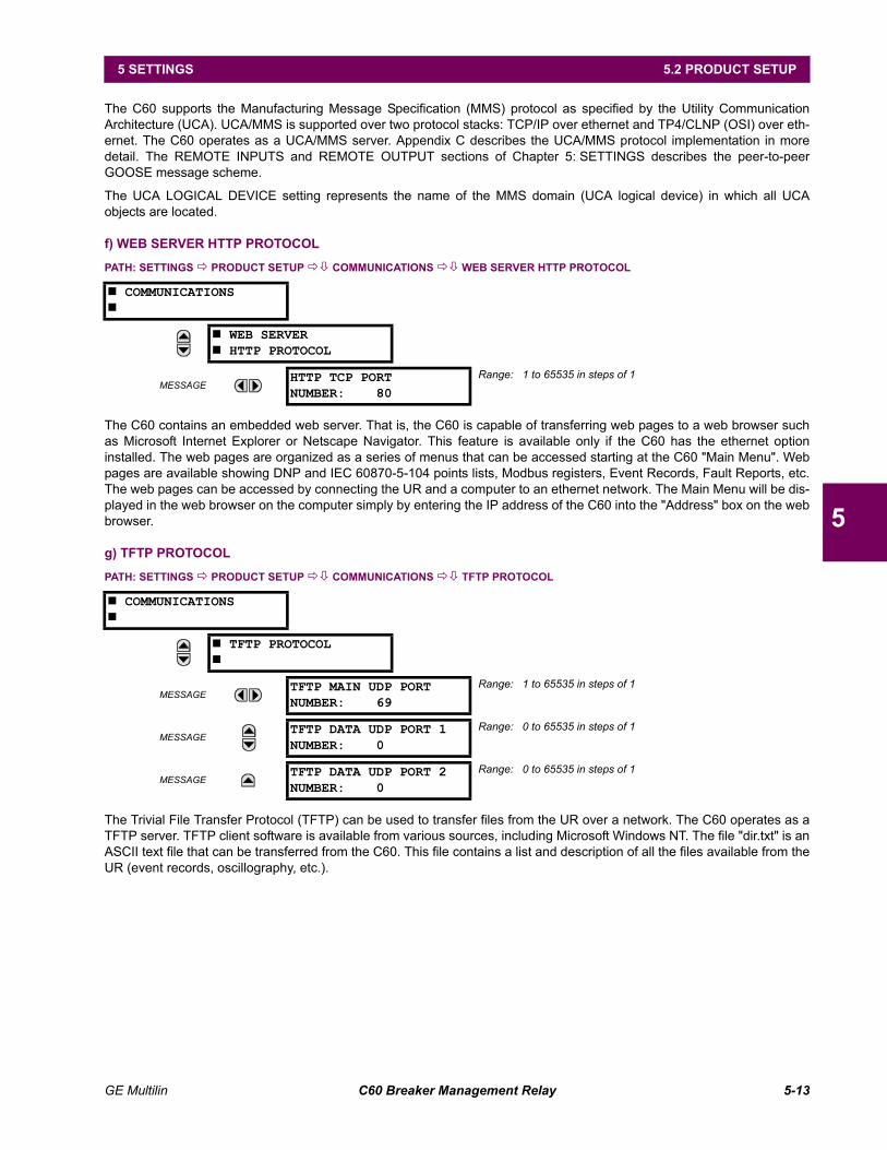
GE Multilin C60 Breaker Management Relay 5-13
5 SETTINGS 5.2 PRODUCT SETUP
5
The C60 supports the Manufacturing Message Specification (MMS) protocol as specified by the Utility CommunicationArchitecture (UCA). UCA/MMS is supported over two protocol stacks: TCP/IP over ethernet and TP4/CLNP (OSI) over eth-ernet. The C60 operates as a UCA/MMS server. Appendix C describes the UCA/MMS protocol implementation in moredetail. The REMOTE INPUTS and REMOTE OUTPUT sections of Chapter 5: SETTINGS describes the peer-to-peerGOOSE message scheme.
The UCA LOGICAL DEVICE setting represents the name of the MMS domain (UCA logical device) in which all UCAobjects are located.
f) WEB SERVER HTTP PROTOCOL
PATH: SETTINGS ! PRODUCT SETUP !" COMMUNICATIONS !" WEB SERVER HTTP PROTOCOL
The C60 contains an embedded web server. That is, the C60 is capable of transferring web pages to a web browser suchas Microsoft Internet Explorer or Netscape Navigator. This feature is available only if the C60 has the ethernet optioninstalled. The web pages are organized as a series of menus that can be accessed starting at the C60 "Main Menu". Webpages are available showing DNP and IEC 60870-5-104 points lists, Modbus registers, Event Records, Fault Reports, etc.The web pages can be accessed by connecting the UR and a computer to an ethernet network. The Main Menu will be dis-played in the web browser on the computer simply by entering the IP address of the C60 into the "Address" box on the webbrowser.
g) TFTP PROTOCOL
PATH: SETTINGS ! PRODUCT SETUP !" COMMUNICATIONS !" TFTP PROTOCOL
The Trivial File Transfer Protocol (TFTP) can be used to transfer files from the UR over a network. The C60 operates as aTFTP server. TFTP client software is available from various sources, including Microsoft Windows NT. The file "dir.txt" is anASCII text file that can be transferred from the C60. This file contains a list and description of all the files available from theUR (event records, oscillography, etc.).
# COMMUNICATIONS#
# WEB SERVER# HTTP PROTOCOL
MESSAGEHTTP TCP PORTNUMBER: 80
Range: 1 to 65535 in steps of 1
# COMMUNICATIONS#
# TFTP PROTOCOL#
MESSAGETFTP MAIN UDP PORTNUMBER: 69
Range: 1 to 65535 in steps of 1
MESSAGETFTP DATA UDP PORT 1NUMBER: 0
Range: 0 to 65535 in steps of 1
MESSAGETFTP DATA UDP PORT 2NUMBER: 0
Range: 0 to 65535 in steps of 1
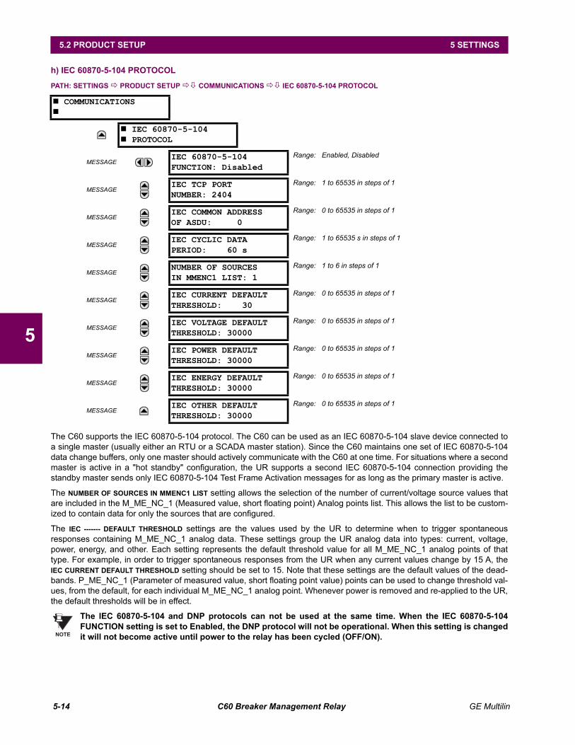
5-14 C60 Breaker Management Relay GE Multilin
5.2 PRODUCT SETUP 5 SETTINGS
5
h) IEC 60870-5-104 PROTOCOL
PATH: SETTINGS ! PRODUCT SETUP !" COMMUNICATIONS !" IEC 60870-5-104 PROTOCOL
The C60 supports the IEC 60870-5-104 protocol. The C60 can be used as an IEC 60870-5-104 slave device connected toa single master (usually either an RTU or a SCADA master station). Since the C60 maintains one set of IEC 60870-5-104data change buffers, only one master should actively communicate with the C60 at one time. For situations where a secondmaster is active in a "hot standby" configuration, the UR supports a second IEC 60870-5-104 connection providing thestandby master sends only IEC 60870-5-104 Test Frame Activation messages for as long as the primary master is active.
The NUMBER OF SOURCES IN MMENC1 LIST setting allows the selection of the number of current/voltage source values thatare included in the M_ME_NC_1 (Measured value, short floating point) Analog points list. This allows the list to be custom-ized to contain data for only the sources that are configured.
The IEC ------- DEFAULT THRESHOLD settings are the values used by the UR to determine when to trigger spontaneousresponses containing M_ME_NC_1 analog data. These settings group the UR analog data into types: current, voltage,power, energy, and other. Each setting represents the default threshold value for all M_ME_NC_1 analog points of thattype. For example, in order to trigger spontaneous responses from the UR when any current values change by 15 A, theIEC CURRENT DEFAULT THRESHOLD setting should be set to 15. Note that these settings are the default values of the dead-bands. P_ME_NC_1 (Parameter of measured value, short floating point value) points can be used to change threshold val-ues, from the default, for each individual M_ME_NC_1 analog point. Whenever power is removed and re-applied to the UR,the default thresholds will be in effect.
The IEC 60870-5-104 and DNP protocols can not be used at the same time. When the IEC 60870-5-104FUNCTION setting is set to Enabled, the DNP protocol will not be operational. When this setting is changedit will not become active until power to the relay has been cycled (OFF/ON).
# COMMUNICATIONS#
# IEC 60870-5-104# PROTOCOL
MESSAGEIEC 60870-5-104FUNCTION: Disabled
Range: Enabled, Disabled
MESSAGEIEC TCP PORTNUMBER: 2404
Range: 1 to 65535 in steps of 1
MESSAGEIEC COMMON ADDRESSOF ASDU: 0
Range: 0 to 65535 in steps of 1
MESSAGEIEC CYCLIC DATAPERIOD: 60 s
Range: 1 to 65535 s in steps of 1
MESSAGENUMBER OF SOURCESIN MMENC1 LIST: 1
Range: 1 to 6 in steps of 1
MESSAGEIEC CURRENT DEFAULTTHRESHOLD: 30
Range: 0 to 65535 in steps of 1
MESSAGEIEC VOLTAGE DEFAULTTHRESHOLD: 30000
Range: 0 to 65535 in steps of 1
MESSAGEIEC POWER DEFAULTTHRESHOLD: 30000
Range: 0 to 65535 in steps of 1
MESSAGEIEC ENERGY DEFAULTTHRESHOLD: 30000
Range: 0 to 65535 in steps of 1
MESSAGEIEC OTHER DEFAULTTHRESHOLD: 30000
Range: 0 to 65535 in steps of 1
NOTE
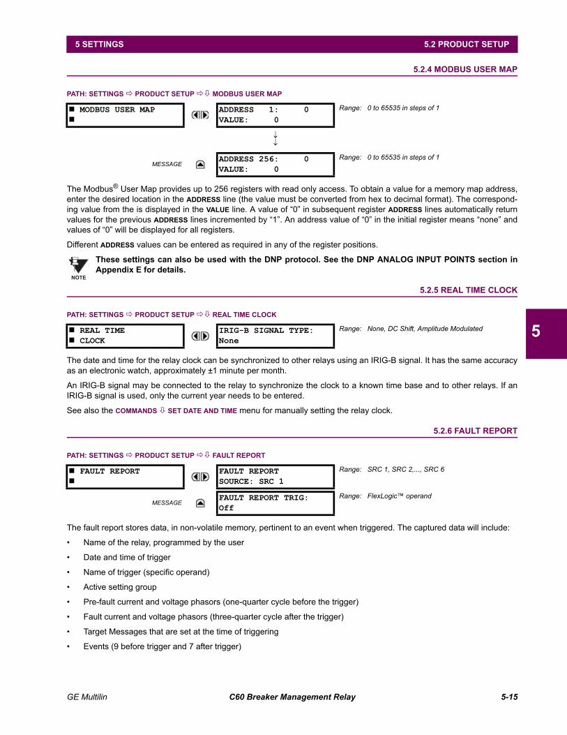
GE Multilin C60 Breaker Management Relay 5-15
5 SETTINGS 5.2 PRODUCT SETUP
5
5.2.4 MODBUS USER MAP
PATH: SETTINGS ! PRODUCT SETUP !" MODBUS USER MAP
The Modbus® User Map provides up to 256 registers with read only access. To obtain a value for a memory map address,enter the desired location in the ADDRESS line (the value must be converted from hex to decimal format). The correspond-ing value from the is displayed in the VALUE line. A value of 0 in subsequent register ADDRESS lines automatically returnvalues for the previous ADDRESS lines incremented by 1. An address value of 0 in the initial register means none andvalues of 0 will be displayed for all registers.
Different ADDRESS values can be entered as required in any of the register positions.
These settings can also be used with the DNP protocol. See the DNP ANALOG INPUT POINTS section inAppendix E for details.
5.2.5 REAL TIME CLOCK
PATH: SETTINGS ! PRODUCT SETUP !" REAL TIME CLOCK
The date and time for the relay clock can be synchronized to other relays using an IRIG-B signal. It has the same accuracyas an electronic watch, approximately ±1 minute per month.
An IRIG-B signal may be connected to the relay to synchronize the clock to a known time base and to other relays. If anIRIG-B signal is used, only the current year needs to be entered.
See also the COMMANDS " SET DATE AND TIME menu for manually setting the relay clock.
5.2.6 FAULT REPORT
PATH: SETTINGS ! PRODUCT SETUP !" FAULT REPORT
The fault report stores data, in non-volatile memory, pertinent to an event when triggered. The captured data will include:
Name of the relay, programmed by the user
Date and time of trigger
Name of trigger (specific operand)
Active setting group
Pre-fault current and voltage phasors (one-quarter cycle before the trigger)
Fault current and voltage phasors (three-quarter cycle after the trigger)
Target Messages that are set at the time of triggering
Events (9 before trigger and 7 after trigger)
# MODBUS USER MAP#
ADDRESS 1: 0VALUE: 0
Range: 0 to 65535 in steps of 1
↓↓
MESSAGEADDRESS 256: 0VALUE: 0
Range: 0 to 65535 in steps of 1
# REAL TIME# CLOCK
IRIG-B SIGNAL TYPE:None
Range: None, DC Shift, Amplitude Modulated
# FAULT REPORT#
FAULT REPORTSOURCE: SRC 1
Range: SRC 1, SRC 2,..., SRC 6
MESSAGEFAULT REPORT TRIG:Off
Range: FlexLogic operand
NOTE

5-16 C60 Breaker Management Relay GE Multilin
5.2 PRODUCT SETUP 5 SETTINGS
5
The captured data also includes the fault type and the distance to the fault location, as well as the reclose shot number(when applicable) The Fault Locator does not report fault type or location if the source VTs are connected in the Delta con-figuration.
The trigger can be any FlexLogic operand, but in most applications it is expected to be the same operand, usually a vir-tual output, that is used to drive an output relay to trip a breaker. To prevent the over-writing of fault events, the disturbancedetector should not be used to trigger a fault report.
If a number of protection elements are ORed to create a fault report trigger, the first operation of any element causing theOR gate output to become high triggers a fault report. However, If other elements operate during the fault and the first oper-ated element has not been reset (the OR gate output is still high), the fault report is not triggered again. Considering thereset time of protection elements, there is very little chance that fault report can be triggered twice in this manner. As thefault report must capture a usable amount of pre and post-fault data, it can not be triggered faster than every 20 ms.
Each fault report is stored as a file; the relay capacity is ten files. An eleventh trigger overwrites the oldest file. The operandselected as the fault report trigger automatically triggers an oscillography record which can also be triggered independently.
URPC is required to view all captured data. The relay faceplate display can be used to view the date and time of trigger, thefault type, the distance location of the fault, and the reclose shot number
The FAULT REPORT SOURCE setting selects the Source for input currents and voltages and disturbance detection. The FAULTREPORT TRIG setting assigns the FlexLogic operand representing the protection element/elements requiring operationalfault location calculations. The distance to fault calculations are initiated by this signal.
See also SETTINGS " SYSTEM SETUP !" LINE menu for specifying line characteristics and the ACTUAL VALUES " RECORDS! FAULT REPORTS menu.
5.2.7 OSCILLOGRAPHY
PATH: SETTINGS ! PRODUCT SETUP !" OSCILLOGRAPHY
# OSCILLOGRAPHY#
NUMBER OF RECORDS:15
Range: 1 to 64 in steps of 1
TRIGGER MODE:Automatic Overwrite
Range: Automatic Overwrite, Protected
TRIGGER POSITION: 50%
Range: 0 to 100 in steps of 1
TRIGGER SOURCE:Off
Range: FlexLogic operand
AC INPUT WAVEFORMS:16 samples/cycle
Range: Off; 8, 16, 32, 64 samples/cycle
# DIGITAL CHANNELS#
Range: 2 to 63 channels
DIGITAL CHANNEL 2:Off
Range: FlexLogic operand
↓
DIGITAL CHANNEL 63:Off
Range: FlexLogic operand
# ANALOG CHANNELS#
Range: 1 to 16 channels
ANALOG CHANNEL 1:Off
Range: Off, any analog Actual Value parameter
↓
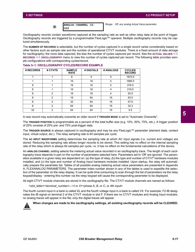
GE Multilin C60 Breaker Management Relay 5-17
5 SETTINGS 5.2 PRODUCT SETUP
5
Oscillography records contain waveforms captured at the sampling rate as well as other relay data at the point of trigger.Oscillography records are triggered by a programmable FlexLogic operand. Multiple oscillography records may be cap-tured simultaneously.
The NUMBER OF RECORDS is selectable, but the number of cycles captured in a single record varies considerably based onother factors such as sample rate and the number of operational CT/VT modules. There is a fixed amount of data storagefor oscillography; the more data captured, the less the number of cycles captured per record. See the ACTUAL VALUES !"RECORDS !" OSCILLOGRAPHY menu to view the number of cycles captured per record. The following table provides sam-ple configurations with corresponding cycles/record.
A new record may automatically overwrite an older record if TRIGGER MODE is set to "Automatic Overwrite".
The TRIGGER POSITION is programmable as a percent of the total buffer size (e.g. 10%, 50%, 75%, etc.). A trigger positionof 25% consists of 25% pre- and 75% post-trigger data.
The TRIGGER SOURCE is always captured in oscillography and may be any FlexLogic parameter (element state, contactinput, virtual output, etc.). The relay sampling rate is 64 samples per cycle.
The AC INPUT WAVEFORMS setting determines the sampling rate at which AC input signals (i.e. current and voltage) arestored. Reducing the sampling rate allows longer records to be stored. This setting has no effect on the internal samplingrate of the relay which is always 64 samples per cycle, i.e. it has no effect on the fundamental calculations of the device.
An ANALOG CHANNEL setting selects the metering actual value recorded in an oscillography trace. The length of each oscil-lography trace depends in part on the number of parameters selected here. Parameters set to Off are ignored. The param-eters available in a given relay are dependent on: (a) the type of relay, (b) the type and number of CT/VT hardware modulesinstalled, and (c) the type and number of Analog Input hardware modules installed. Upon startup, the relay will automati-cally prepare the parameter list. Tables of all possible analog metering actual value parameters are presented in AppendixA: FLEXANALOG PARAMETERS. The parameter index number shown in any of the tables is used to expedite the selec-tion of the parameter on the relay display. It can be quite time-consuming to scan through the list of parameters via the relaykeypad/display - entering this number via the relay keypad will cause the corresponding parameter to be displayed.
All eight CT/VT module channels are stored in the oscillography file. The CT/VT module channels are named as follows:
<slot_letter><terminal_number><I or V><phase A, B, or C, or 4th input>
The fourth current input in a bank is called IG, and the fourth voltage input in a bank is called VX. For example, F2-IB desig-nates the IB signal on terminal 2 of the CT/VT module in slot F. If there are no CT/VT modules and Analog Input modules,no analog traces will appear in the file; only the digital traces will appear.
When changes are made to the oscillography settings, all existing oscillography records will be CLEARED.
ANALOG CHANNEL 16:Off
Range: Off, any analog Actual Value parameter
Table 51: OSCILLOGRAPHY CYCLES/RECORD EXAMPLE# RECORDS # CT/VTS SAMPLE
RATE# DIGITALS # ANALOGS CYCLES/
RECORD1 1 8 0 0 1872.01 1 16 16 0 1685.08 1 16 16 0 276.08 1 16 16 4 219.58 2 16 16 4 93.58 2 16 64 16 93.58 2 32 64 16 57.68 2 64 64 16 32.3
32 2 64 64 16 9.5
WARNING

5-18 C60 Breaker Management Relay GE Multilin
5.2 PRODUCT SETUP 5 SETTINGS
5
5.2.8 DATA LOGGER
PATH: SETTINGS !" PRODUCT SETUP !" DATA LOGGER
The data logger samples and records up to 16 analog parameters at a user-defined sampling rate. This recorded data maybe downloaded to the URPC software and displayed with parameters on the vertical axis and time on the horizontal axis.All data is stored in non-volatile memory, meaning that the information is retained when power to the relay is lost.
For a fixed sampling rate, the data logger can be configured with a few channels over a long period or a larger number ofchannels for a shorter period. The relay automatically partitions the available memory between the channels in use.
Changing any setting affecting Data Logger operation will clear any data that is currently in the log.
DATA LOGGER RATE:
This setting selects the time interval at which the actual value data will be recorded.
DATA LOGGER CHNL 1 (to 16):
This setting selects the metering actual value that is to be recorded in Channel 1(16) of the data log. The parameters avail-able in a given relay are dependent on: the type of relay, the type and number of CT/VT hardware modules installed, andthe type and number of Analog Input hardware modules installed. Upon startup, the relay will automatically prepare theparameter list. Tables of all possible analog metering actual value parameters are presented in Appendix A: FLEXANALOGPARAMETERS. The parameter index number shown in any of the tables is used to expedite the selection of the parameteron the relay display. It can be quite time-consuming to scan through the list of parameters via the relay keypad/display entering this number via the relay keypad will cause the corresponding parameter to be displayed.
DATA LOGGER CONFIG:
This display presents the total amount of time the Data Logger can record the channels not selected to "Off" without over-writing old data.
5.2.9 DEMAND
PATH: SETTINGS ! PRODUCT SETUP !" DEMAND
# DATA LOGGER#
DATA LOGGER RATE:1 min
Range: 1 sec; 1 min, 5 min, 10 min, 15 min, 20 min, 30min, 60 min
MESSAGEDATA LOGGER CHNL 1:Off
Range: Off, any analog Actual Value parameter
MESSAGEDATA LOGGER CHNL 2:Off
Range: Off, any analog Actual Value parameter
↓
MESSAGEDATA LOGGER CHNL 16:Off
Range: Off, any analog Actual Value parameter
MESSAGEDATA LOGGER CONFIG:0 CHNL x 0.0 DAYS
Range: Not applicable - shows computed data only
# DEMAND#
CRNT DEMAND METHOD:Thermal Exponential
Range: Thermal Exponential, Block Interval,Rolling Demand
MESSAGEPOWER DEMAND METHOD:Thermal Exponential
Range: Thermal Exponential, Block Interval,Rolling Demand
MESSAGEDEMAND INTERVAL:15 MIN
Range: 5, 10, 15, 20, 30, 60 minutes
MESSAGEDEMAND TRIGGER:Off
Range: FlexLogic operandNote: for calculation using Method 2a
NOTE
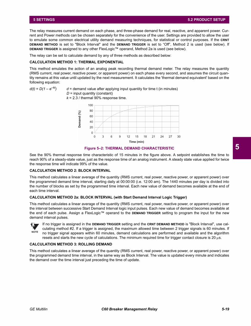
GE Multilin C60 Breaker Management Relay 5-19
5 SETTINGS 5.2 PRODUCT SETUP
5
The relay measures current demand on each phase, and three-phase demand for real, reactive, and apparent power. Cur-rent and Power methods can be chosen separately for the convenience of the user. Settings are provided to allow the userto emulate some common electrical utility demand measuring techniques, for statistical or control purposes. If the CRNTDEMAND METHOD is set to "Block Interval" and the DEMAND TRIGGER is set to Off, Method 2 is used (see below). IfDEMAND TRIGGER is assigned to any other FlexLogic operand, Method 2a is used (see below).
The relay can be set to calculate demand by any of three methods as described below:
CALCULATION METHOD 1: THERMAL EXPONENTIAL
This method emulates the action of an analog peak recording thermal demand meter. The relay measures the quantity(RMS current, real power, reactive power, or apparent power) on each phase every second, and assumes the circuit quan-tity remains at this value until updated by the next measurement. It calculates the 'thermal demand equivalent' based on thefollowing equation:
d(t) = D(1 ekt) d = demand value after applying input quantity for time t (in minutes)D = input quantity (constant)k = 2.3 / thermal 90% response time.
Figure 52: THERMAL DEMAND CHARACTERISTIC
See the 90% thermal response time characteristic of 15 minutes in the figure above. A setpoint establishes the time toreach 90% of a steady-state value, just as the response time of an analog instrument. A steady state value applied for twicethe response time will indicate 99% of the value.
CALCULATION METHOD 2: BLOCK INTERVAL
This method calculates a linear average of the quantity (RMS current, real power, reactive power, or apparent power) overthe programmed demand time interval, starting daily at 00:00:00 (i.e. 12:00 am). The 1440 minutes per day is divided intothe number of blocks as set by the programmed time interval. Each new value of demand becomes available at the end ofeach time interval.
CALCULATION METHOD 2a: BLOCK INTERVAL (with Start Demand Interval Logic Trigger)
This method calculates a linear average of the quantity (RMS current, real power, reactive power, or apparent power) overthe interval between successive Start Demand Interval logic input pulses. Each new value of demand becomes available atthe end of each pulse. Assign a FlexLogic operand to the DEMAND TRIGGER setting to program the input for the newdemand interval pulses.
If no trigger is assigned in the DEMAND TRIGGER setting and the CRNT DEMAND METHOD is "Block Interval", use cal-culating method #2. If a trigger is assigned, the maximum allowed time between 2 trigger signals is 60 minutes. Ifno trigger signal appears within 60 minutes, demand calculations are performed and available and the algorithmresets and starts the new cycle of calculations. The minimum required time for trigger contact closure is 20 µs.
CALCULATION METHOD 3: ROLLING DEMAND
This method calculates a linear average of the quantity (RMS current, real power, reactive power, or apparent power) overthe programmed demand time interval, in the same way as Block Interval. The value is updated every minute and indicatesthe demand over the time interval just preceding the time of update.
Time (min)
Dem
an
d(%
)
0
20
40
60
80
100
0 3 6 9 12 15 18 21 24 27 30
NOTE
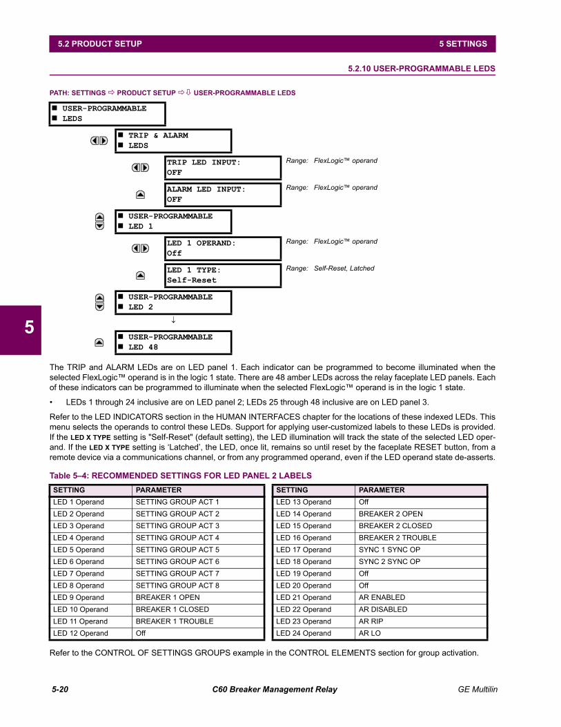
5-20 C60 Breaker Management Relay GE Multilin
5.2 PRODUCT SETUP 5 SETTINGS
5
5.2.10 USER-PROGRAMMABLE LEDS
PATH: SETTINGS ! PRODUCT SETUP !" USER-PROGRAMMABLE LEDS
The TRIP and ALARM LEDs are on LED panel 1. Each indicator can be programmed to become illuminated when theselected FlexLogic operand is in the logic 1 state. There are 48 amber LEDs across the relay faceplate LED panels. Eachof these indicators can be programmed to illuminate when the selected FlexLogic operand is in the logic 1 state.
LEDs 1 through 24 inclusive are on LED panel 2; LEDs 25 through 48 inclusive are on LED panel 3.
Refer to the LED INDICATORS section in the HUMAN INTERFACES chapter for the locations of these indexed LEDs. Thismenu selects the operands to control these LEDs. Support for applying user-customized labels to these LEDs is provided.If the LED X TYPE setting is "Self-Reset" (default setting), the LED illumination will track the state of the selected LED oper-and. If the LED X TYPE setting is Latched, the LED, once lit, remains so until reset by the faceplate RESET button, from aremote device via a communications channel, or from any programmed operand, even if the LED operand state de-asserts.
Refer to the CONTROL OF SETTINGS GROUPS example in the CONTROL ELEMENTS section for group activation.
# USER-PROGRAMMABLE# LEDS
# TRIP & ALARM# LEDS
TRIP LED INPUT:OFF
Range: FlexLogic operand
ALARM LED INPUT:OFF
Range: FlexLogic operand
# USER-PROGRAMMABLE# LED 1
LED 1 OPERAND:Off
Range: FlexLogic operand
LED 1 TYPE:Self-Reset
Range: Self-Reset, Latched
# USER-PROGRAMMABLE# LED 2
↓
# USER-PROGRAMMABLE# LED 48
Table 54: RECOMMENDED SETTINGS FOR LED PANEL 2 LABELSSETTING PARAMETER SETTING PARAMETERLED 1 Operand SETTING GROUP ACT 1 LED 13 Operand OffLED 2 Operand SETTING GROUP ACT 2 LED 14 Operand BREAKER 2 OPENLED 3 Operand SETTING GROUP ACT 3 LED 15 Operand BREAKER 2 CLOSEDLED 4 Operand SETTING GROUP ACT 4 LED 16 Operand BREAKER 2 TROUBLELED 5 Operand SETTING GROUP ACT 5 LED 17 Operand SYNC 1 SYNC OPLED 6 Operand SETTING GROUP ACT 6 LED 18 Operand SYNC 2 SYNC OPLED 7 Operand SETTING GROUP ACT 7 LED 19 Operand OffLED 8 Operand SETTING GROUP ACT 8 LED 20 Operand OffLED 9 Operand BREAKER 1 OPEN LED 21 Operand AR ENABLEDLED 10 Operand BREAKER 1 CLOSED LED 22 Operand AR DISABLEDLED 11 Operand BREAKER 1 TROUBLE LED 23 Operand AR RIPLED 12 Operand Off LED 24 Operand AR LO
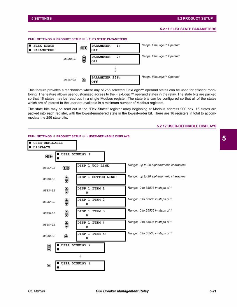
GE Multilin C60 Breaker Management Relay 5-21
5 SETTINGS 5.2 PRODUCT SETUP
5
5.2.11 FLEX STATE PARAMETERS
PATH: SETTINGS ! PRODUCT SETUP !" FLEX STATE PARAMETERS
This feature provides a mechanism where any of 256 selected FlexLogic operand states can be used for efficient moni-toring. The feature allows user-customized access to the FlexLogic operand states in the relay. The state bits are packedso that 16 states may be read out in a single Modbus register. The state bits can be configured so that all of the stateswhich are of interest to the user are available in a minimum number of Modbus registers.
The state bits may be read out in the "Flex States" register array beginning at Modbus address 900 hex. 16 states arepacked into each register, with the lowest-numbered state in the lowest-order bit. There are 16 registers in total to accom-modate the 256 state bits.
5.2.12 USER-DEFINABLE DISPLAYS
PATH: SETTINGS ! PRODUCT SETUP !" USER-DEFINABLE DISPLAYS
# FLEX STATE# PARAMETERS
PARAMETER 1:Off
Range: FlexLogic Operand
MESSAGEPARAMETER 2:Off
Range: FlexLogic Operand
↓↓
MESSAGEPARAMETER 256:Off
Range: FlexLogic Operand
# USER-DEFINABLE# DISPLAYS
# USER DISPLAY 1#
MESSAGEDISP 1 TOP LINE: Range: up to 20 alphanumeric characters
MESSAGEDISP 1 BOTTOM LINE: Range: up to 20 alphanumeric characters
MESSAGEDISP 1 ITEM 1 0
Range: 0 to 65535 in steps of 1
MESSAGEDISP 1 ITEM 2 0
Range: 0 to 65535 in steps of 1
MESSAGEDISP 1 ITEM 3 0
Range: 0 to 65535 in steps of 1
MESSAGEDISP 1 ITEM 4 0
Range: 0 to 65535 in steps of 1
MESSAGEDISP 1 ITEM 5: 0
Range: 0 to 65535 in steps of 1
# USER DISPLAY 2#
↓
# USER DISPLAY 8#
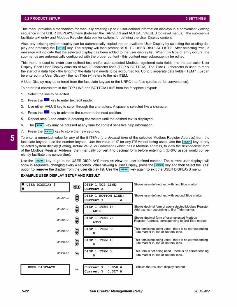
5-22 C60 Breaker Management Relay GE Multilin
5.2 PRODUCT SETUP 5 SETTINGS
5
This menu provides a mechanism for manually creating up to 8 user-defined information displays in a convenient viewingsequence in the USER DISPLAYS menu (between the TARGETS and ACTUAL VALUES top-level menus). The sub-menusfacilitate text entry and Modbus Register data pointer options for defining the User Display content.
Also, any existing system display can be automatically copied into an available User Display by selecting the existing dis-play and pressing the key. The display will then prompt ADD TO USER DISPLAY LIST?. After selecting Yes, amessage will indicate that the selected display has been added to the user display list. When this type of entry occurs, thesub-menus are automatically configured with the proper content - this content may subsequently be edited.
This menu is used to enter user-defined text and/or user-selected Modbus-registered data fields into the particular UserDisplay. Each User Display consists of two 20-character lines (TOP & BOTTOM). The Tilde (~) character is used to markthe start of a data field - the length of the data field needs to be accounted for. Up to 5 separate data fields (ITEM 1...5) canbe entered in a User Display - the nth Tilde (~) refers to the nth ITEM.
A User Display may be entered from the faceplate keypad or the URPC interface (preferred for convenience).
To enter text characters in the TOP LINE and BOTTOM LINE from the faceplate keypad:
1. Select the line to be edited.
2. Press the key to enter text edit mode.
3. Use either VALUE key to scroll through the characters. A space is selected like a character.
4. Press the key to advance the cursor to the next position.
5. Repeat step 3 and continue entering characters until the desired text is displayed.
6. The key may be pressed at any time for context sensitive help information.
7. Press the key to store the new settings.
To enter a numerical value for any of the 5 ITEMs (the decimal form of the selected Modbus Register Address) from thefaceplate keypad, use the number keypad. Use the value of 0 for any ITEMs not being used. Use the key at anyselected system display (Setting, Actual Value, or Command) which has a Modbus address, to view the hexadecimal formof the Modbus Register Address, then manually convert it to decimal form before entering it (URPC usage would conve-niently facilitate this conversion).
Use the key to go to the USER DISPLAYS menu to view the user-defined content. The current user displays willshow in sequence, changing every 4 seconds. While viewing a User Display, press the key and then select the Yesoption to remove the display from the user display list. Use the key again to exit the USER DISPLAYS menu.
EXAMPLE USER DISPLAY SETUP AND RESULT:
# USER DISPLAY 1#
DISP 1 TOP LINE:Current X ~ A
Shows user-defined text with first Tilde marker.
MESSAGEDISP 1 BOTTOM LINE:Current Y ~ A
Shows user-defined text with second Tilde marker.
MESSAGEDISP 1 ITEM 1:
6016Shows decimal form of user-selected Modbus Register Address, corresponding to first Tilde marker.
MESSAGEDISP 1 ITEM 2:
6357Shows decimal form of user-selected Modbus Register Address, corresponding to 2nd Tilde marker.
MESSAGEDISP 1 ITEM 3:
0This item is not being used - there is no corresponding Tilde marker in Top or Bottom lines.
MESSAGEDISP 1 ITEM 4:
0This item is not being used - there is no corresponding Tilde marker in Top or Bottom lines.
MESSAGEDISP 1 ITEM 5:
0This item is not being used - there is no correspondingTilde marker in Top or Bottom lines.
USER DISPLAYS→
Current X 0.850 ACurrent Y 0.327 A
Shows the resultant display content.
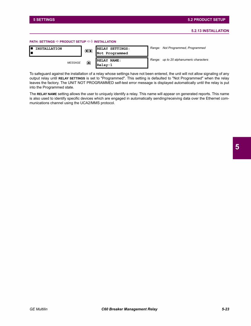
GE Multilin C60 Breaker Management Relay 5-23
5 SETTINGS 5.2 PRODUCT SETUP
5
5.2.13 INSTALLATION
PATH: SETTINGS ! PRODUCT SETUP !" INSTALLATION
To safeguard against the installation of a relay whose settings have not been entered, the unit will not allow signaling of anyoutput relay until RELAY SETTINGS is set to "Programmed". This setting is defaulted to "Not Programmed" when the relayleaves the factory. The UNIT NOT PROGRAMMED self-test error message is displayed automatically until the relay is putinto the Programmed state.
The RELAY NAME setting allows the user to uniquely identify a relay. This name will appear on generated reports. This nameis also used to identify specific devices which are engaged in automatically sending/receiving data over the Ethernet com-munications channel using the UCA2/MMS protocol.
# INSTALLATION#
RELAY SETTINGS:Not Programmed
Range: Not Programmed, Programmed
MESSAGERELAY NAME:Relay-1
Range: up to 20 alphanumeric characters
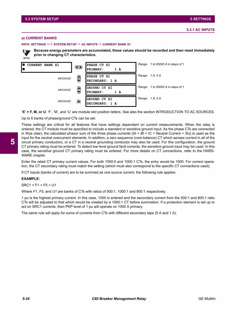
5-24 C60 Breaker Management Relay GE Multilin
5.3 SYSTEM SETUP 5 SETTINGS
5
5.3 SYSTEM SETUP 5.3.1 AC INPUTS
a) CURRENT BANKSPATH: SETTINGS !" SYSTEM SETUP ! AC INPUTS ! CURRENT BANK X1
Because energy parameters are accumulated, these values should be recorded and then reset immediatelyprior to changing CT characteristics.
X = F, M, or U. F, M, and U are module slot position letters. See also the section INTRODUCTION TO AC SOURCES.
Up to 6 banks of phase/ground CTs can be set.
These settings are critical for all features that have settings dependent on current measurements. When the relay isordered, the CT module must be specified to include a standard or sensitive ground input. As the phase CTs are connectedin Wye (star), the calculated phasor sum of the three phase currents (IA + IB + IC = Neutral Current = 3Io) is used as theinput for the neutral overcurrent elements. In addition, a zero sequence (core balance) CT which senses current in all of thecircuit primary conductors, or a CT in a neutral grounding conductor may also be used. For this configuration, the groundCT primary rating must be entered. To detect low level ground fault currents, the sensitive ground input may be used. In thiscase, the sensitive ground CT primary rating must be entered. For more details on CT connections, refer to the HARD-WARE chapter.
Enter the rated CT primary current values. For both 1000:5 and 1000:1 CTs, the entry would be 1000. For correct opera-tion, the CT secondary rating must match the setting (which must also correspond to the specific CT connections used).
If CT inputs (banks of current) are to be summed as one source current, the following rule applies:
EXAMPLE:
SRC1 = F1 + F5 + U1
Where F1, F5, and U1 are banks of CTs with ratios of 500:1, 1000:1 and 800:1 respectively.
1 pu is the highest primary current. In this case, 1000 is entered and the secondary current from the 500:1 and 800:1 ratioCTs will be adjusted to that which would be created by a 1000:1 CT before summation. If a protection element is set up toact on SRC1 currents, then PKP level of 1 pu will operate on 1000 A primary.
The same rule will apply for sums of currents from CTs with different secondary taps (5 A and 1 A).
# CURRENT BANK X1#
PHASE CT X1PRIMARY: 1 A
Range: 1 to 65000 A in steps of 1
MESSAGEPHASE CT X1SECONDARY: 1 A
Range: 1 A, 5 A
MESSAGEGROUND CT X1PRIMARY: 1 A
Range: 1 to 65000 A in steps of 1
MESSAGEGROUND CT X1SECONDARY: 1 A
Range: 1 A, 5 A
NOTE
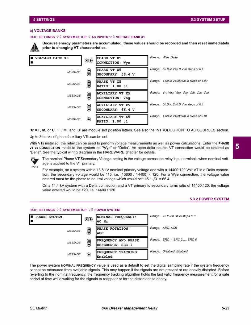
GE Multilin C60 Breaker Management Relay 5-25
5 SETTINGS 5.3 SYSTEM SETUP
5
b) VOLTAGE BANKSPATH: SETTINGS !" SYSTEM SETUP ! AC INPUTS !" VOLTAGE BANK X1
Because energy parameters are accumulated, these values should be recorded and then reset immediatelyprior to changing VT characteristics.
X = F, M, or U. F, M, and U are module slot position letters. See also the INTRODUCTION TO AC SOURCES section.
Up to 3 banks of phase/auxiliary VTs can be set.
With VTs installed, the relay can be used to perform voltage measurements as well as power calculations. Enter the PHASEVT xx CONNECTION made to the system as "Wye" or "Delta". An open-delta source VT connection would be entered as"Delta". See the typical wiring diagram in the HARDWARE chapter for details.
The nominal Phase VT Secondary Voltage setting is the voltage across the relay input terminals when nominal volt-age is applied to the VT primary.
For example, on a system with a 13.8 kV nominal primary voltage and with a 14400:120 Volt VT in a Delta connec-tion, the secondary voltage would be 115, i.e. (13800 / 14400) × 120. For a Wye connection, the voltage valueentered must be the phase to neutral voltage which would be 115 / = 66.4.
On a 14.4 kV system with a Delta connection and a VT primary to secondary turns ratio of 14400:120, the voltagevalue entered would be 120, i.e. 14400 / 120.
5.3.2 POWER SYSTEM
PATH: SETTINGS !" SYSTEM SETUP !" POWER SYSTEM
The power system NOMINAL FREQUENCY value is used as a default to set the digital sampling rate if the system frequencycannot be measured from available signals. This may happen if the signals are not present or are heavily distorted. Beforereverting to the nominal frequency, the frequency tracking algorithm holds the last valid frequency measurement for a safeperiod of time while waiting for the signals to reappear or for the distortions to decay.
# VOLTAGE BANK X5#
PHASE VT X5CONNECTION: Wye
Range: Wye, Delta
MESSAGEPHASE VT X5SECONDARY: 66.4 V
Range: 50.0 to 240.0 V in steps of 0.1
MESSAGEPHASE VT X5RATIO: 1.00 :1
Range: 1.00 to 24000.00 in steps of 1.00
MESSAGEAUXILIARY VT X5CONNECTION: Vag
Range: Vn, Vag, Vbg, Vcg, Vab, Vbc, Vca
MESSAGEAUXILIARY VT X5SECONDARY: 66.4 V
Range: 50.0 to 240.0 V in steps of 0.1
MESSAGEAUXILIARY VT X5RATIO: 1.00 :1
Range: 1.00 to 24000.00 in steps of 0.01
# POWER SYSTEM#
NOMINAL FREQUENCY:60 Hz
Range: 25 to 60 Hz in steps of 1
MESSAGEPHASE ROTATION:ABC
Range: ABC, ACB
MESSAGEFREQUENCY AND PHASEREFERENCE: SRC 1
Range: SRC 1, SRC 2,..., SRC 6
MESSAGEFREQUENCY TRACKING:Enabled
Range: Disabled, Enabled
CAUTION
NOTE
3
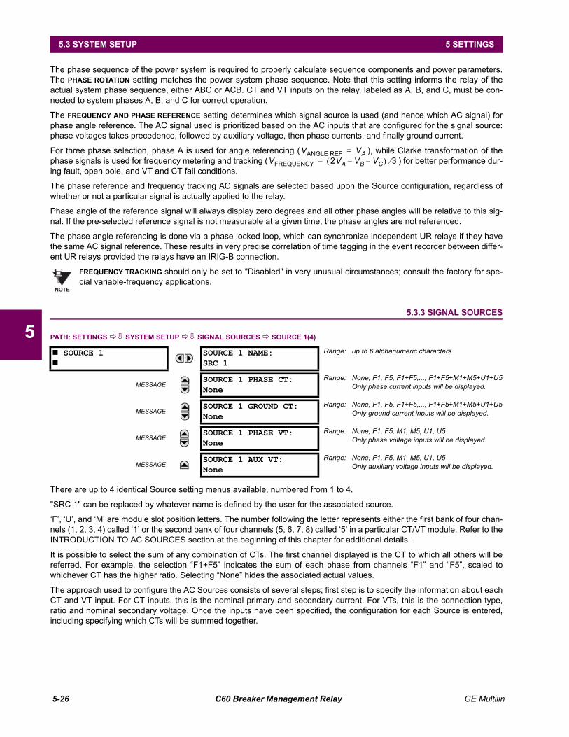
5-26 C60 Breaker Management Relay GE Multilin
5.3 SYSTEM SETUP 5 SETTINGS
5
The phase sequence of the power system is required to properly calculate sequence components and power parameters.The PHASE ROTATION setting matches the power system phase sequence. Note that this setting informs the relay of theactual system phase sequence, either ABC or ACB. CT and VT inputs on the relay, labeled as A, B, and C, must be con-nected to system phases A, B, and C for correct operation.
The FREQUENCY AND PHASE REFERENCE setting determines which signal source is used (and hence which AC signal) forphase angle reference. The AC signal used is prioritized based on the AC inputs that are configured for the signal source:phase voltages takes precedence, followed by auxiliary voltage, then phase currents, and finally ground current.
For three phase selection, phase A is used for angle referencing ( ), while Clarke transformation of thephase signals is used for frequency metering and tracking ( ) for better performance dur-ing fault, open pole, and VT and CT fail conditions.
The phase reference and frequency tracking AC signals are selected based upon the Source configuration, regardless ofwhether or not a particular signal is actually applied to the relay.
Phase angle of the reference signal will always display zero degrees and all other phase angles will be relative to this sig-nal. If the pre-selected reference signal is not measurable at a given time, the phase angles are not referenced.
The phase angle referencing is done via a phase locked loop, which can synchronize independent UR relays if they havethe same AC signal reference. These results in very precise correlation of time tagging in the event recorder between differ-ent UR relays provided the relays have an IRIG-B connection.
FREQUENCY TRACKING should only be set to "Disabled" in very unusual circumstances; consult the factory for spe-cial variable-frequency applications.
5.3.3 SIGNAL SOURCES
PATH: SETTINGS !" SYSTEM SETUP !" SIGNAL SOURCES ! SOURCE 1(4)
There are up to 4 identical Source setting menus available, numbered from 1 to 4.
"SRC 1" can be replaced by whatever name is defined by the user for the associated source.
F, U, and M are module slot position letters. The number following the letter represents either the first bank of four chan-nels (1, 2, 3, 4) called 1 or the second bank of four channels (5, 6, 7, 8) called 5 in a particular CT/VT module. Refer to theINTRODUCTION TO AC SOURCES section at the beginning of this chapter for additional details.
It is possible to select the sum of any combination of CTs. The first channel displayed is the CT to which all others will bereferred. For example, the selection F1+F5 indicates the sum of each phase from channels F1 and F5, scaled towhichever CT has the higher ratio. Selecting None hides the associated actual values.
The approach used to configure the AC Sources consists of several steps; first step is to specify the information about eachCT and VT input. For CT inputs, this is the nominal primary and secondary current. For VTs, this is the connection type,ratio and nominal secondary voltage. Once the inputs have been specified, the configuration for each Source is entered,including specifying which CTs will be summed together.
# SOURCE 1#
SOURCE 1 NAME:SRC 1
Range: up to 6 alphanumeric characters
MESSAGESOURCE 1 PHASE CT:None
Range: None, F1, F5, F1+F5,..., F1+F5+M1+M5+U1+U5Only phase current inputs will be displayed.
MESSAGESOURCE 1 GROUND CT:None
Range: None, F1, F5, F1+F5,..., F1+F5+M1+M5+U1+U5Only ground current inputs will be displayed.
MESSAGESOURCE 1 PHASE VT:None
Range: None, F1, F5, M1, M5, U1, U5Only phase voltage inputs will be displayed.
MESSAGESOURCE 1 AUX VT:None
Range: None, F1, F5, M1, M5, U1, U5Only auxiliary voltage inputs will be displayed.
VANGLE REF VA=VFREQUENCY 2VA VB– VC–( ) 3⁄=
NOTE
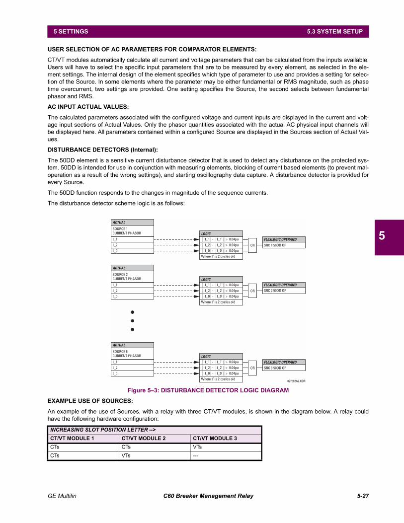
GE Multilin C60 Breaker Management Relay 5-27
5 SETTINGS 5.3 SYSTEM SETUP
5
USER SELECTION OF AC PARAMETERS FOR COMPARATOR ELEMENTS:
CT/VT modules automatically calculate all current and voltage parameters that can be calculated from the inputs available.Users will have to select the specific input parameters that are to be measured by every element, as selected in the ele-ment settings. The internal design of the element specifies which type of parameter to use and provides a setting for selec-tion of the Source. In some elements where the parameter may be either fundamental or RMS magnitude, such as phasetime overcurrent, two settings are provided. One setting specifies the Source, the second selects between fundamentalphasor and RMS.
AC INPUT ACTUAL VALUES:
The calculated parameters associated with the configured voltage and current inputs are displayed in the current and volt-age input sections of Actual Values. Only the phasor quantities associated with the actual AC physical input channels willbe displayed here. All parameters contained within a configured Source are displayed in the Sources section of Actual Val-ues.
DISTURBANCE DETECTORS (Internal):
The 50DD element is a sensitive current disturbance detector that is used to detect any disturbance on the protected sys-tem. 50DD is intended for use in conjunction with measuring elements, blocking of current based elements (to prevent mal-operation as a result of the wrong settings), and starting oscillography data capture. A disturbance detector is provided forevery Source.
The 50DD function responds to the changes in magnitude of the sequence currents.
The disturbance detector scheme logic is as follows:
Figure 53: DISTURBANCE DETECTOR LOGIC DIAGRAM
EXAMPLE USE OF SOURCES:
An example of the use of Sources, with a relay with three CT/VT modules, is shown in the diagram below. A relay couldhave the following hardware configuration:
INCREASING SLOT POSITION LETTER -->CT/VT MODULE 1 CT/VT MODULE 2 CT/VT MODULE 3CTs CTs VTsCTs VTs ---
827092A2.CDR
SOURCE 1CURRENT PHASOR
SOURCE 2CURRENT PHASOR
SOURCE 6CURRENT PHASOR
LOGIC
LOGIC
LOGIC
ACTUAL
ACTUAL
ACTUAL
FLEXLOGIC OPERAND
FLEXLOGIC OPERAND
FLEXLOGIC OPERAND
I_1
I_1
I_1
SRC 1 50DD OP
SRC 2 50DD OP
SRC 6 50DD OP
I_2
I_2
I_2
I_0
I_0
I_0
OR
OR
OR
Where ’ is 2 cycles oldI
Where ’ is 2 cycles oldI
Where ’ is 2 cycles oldI
I I_1 - _1’ > 0.04pu
I I_1 - _1’ > 0.04pu
I I_1 - _1’ > 0.04pu
I I_2 - _2’ > 0.04pu
I I_2 - _2’ > 0.04pu
I I_2 - _2’ > 0.04pu
I I_0 - _0’ > 0.04pu
I I_0 - _0’ > 0.04pu
I I_0 - _0’ > 0.04pu
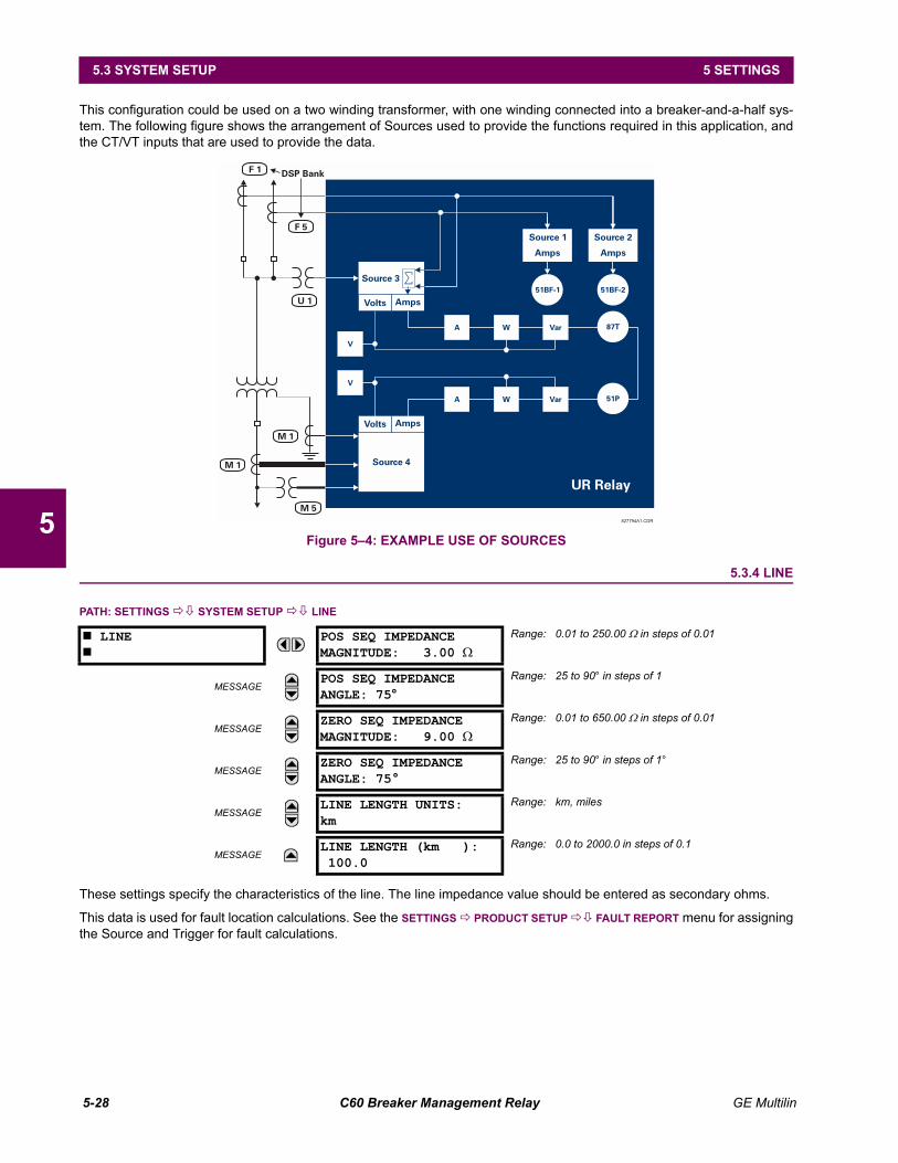
5-28 C60 Breaker Management Relay GE Multilin
5.3 SYSTEM SETUP 5 SETTINGS
5
This configuration could be used on a two winding transformer, with one winding connected into a breaker-and-a-half sys-tem. The following figure shows the arrangement of Sources used to provide the functions required in this application, andthe CT/VT inputs that are used to provide the data.
Figure 54: EXAMPLE USE OF SOURCES
5.3.4 LINE
PATH: SETTINGS !" SYSTEM SETUP !" LINE
These settings specify the characteristics of the line. The line impedance value should be entered as secondary ohms.
This data is used for fault location calculations. See the SETTINGS ! PRODUCT SETUP !" FAULT REPORT menu for assigningthe Source and Trigger for fault calculations.
# LINE#
POS SEQ IMPEDANCEMAGNITUDE: 3.00 Ω
Range: 0.01 to 250.00 Ω in steps of 0.01
MESSAGEPOS SEQ IMPEDANCEANGLE: 75°
Range: 25 to 90° in steps of 1
MESSAGEZERO SEQ IMPEDANCEMAGNITUDE: 9.00 Ω
Range: 0.01 to 650.00 Ω in steps of 0.01
MESSAGEZERO SEQ IMPEDANCEANGLE: 75°
Range: 25 to 90° in steps of 1°
MESSAGELINE LENGTH UNITS:km
Range: km, miles
MESSAGELINE LENGTH (km ):100.0
Range: 0.0 to 2000.0 in steps of 0.1
827794A1.CDR
F 5
F 1DSP Bank
U 1
M 1
M 1
M 5
51BF-1 51BF-2
Source 4
87T
51P
UR Relay
A
V
V
A
W
W
Var
Var
Amps
Source 1
Source 3
Volts Amps
AmpsVolts
Amps
Source 2
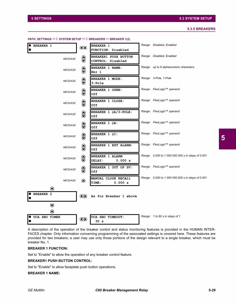
GE Multilin C60 Breaker Management Relay 5-29
5 SETTINGS 5.3 SYSTEM SETUP
5
5.3.5 BREAKERS
PATH: SETTINGS !" SYSTEM SETUP !" BREAKERS ! BREAKER 1(2)
A description of the operation of the breaker control and status monitoring features is provided in the HUMAN INTER-FACES chapter. Only information concerning programming of the associated settings is covered here. These features areprovided for two breakers; a user may use only those portions of the design relevant to a single breaker, which must bebreaker No. 1.
BREAKER 1 FUNCTION:
Set to "Enable" to allow the operation of any breaker control feature.
BREAKER1 PUSH BUTTON CONTROL:
Set to "Enable" to allow faceplate push button operations.
BREAKER 1 NAME:
# BREAKER 1#
BREAKER 1FUNCTION: Disabled
Range: Disabled, Enabled
MESSAGEBREAKER1 PUSH BUTTONCONTROL: Disabled
Range: Disabled, Enabled
MESSAGEBREAKER 1 NAME:Bkr 1
Range: up to 6 alphanumeric characters
MESSAGEBREAKER 1 MODE:3-Pole
Range: 3-Pole, 1-Pole
MESSAGEBREAKER 1 OPEN:Off
Range: FlexLogic operand
MESSAGEBREAKER 1 CLOSE:Off
Range: FlexLogic operand
MESSAGEBREAKER 1 φA/3-POLE:Off
Range: FlexLogic operand
MESSAGEBREAKER 1 φB:Off
Range: FlexLogic operand
MESSAGEBREAKER 1 φC:Off
Range: FlexLogic operand
MESSAGEBREAKER 1 EXT ALARM:Off
Range: FlexLogic operand
MESSAGEBREAKER 1 ALARMDELAY: 0.000 s
Range: 0.000 to 1 000 000.000 s in steps of 0.001
MESSAGEBREAKER 1 OUT OF SV:Off
Range: FlexLogic operand
MESSAGEMANUAL CLOSE RECAL1TIME: 0.000 s
Range: 0.000 to 1 000 000.000 s in steps of 0.001
# BREAKER 2#
As for Breaker 1 above
# UCA SBO TIMER#
UCA SBO TIMEOUT:30 s
Range: 1 to 60 s in steps of 1
5-30 C60 Breaker Management Relay GE Multilin
5.3 SYSTEM SETUP 5 SETTINGS
5
Assign a user-defined name (up to 6 characters) to the breaker. This name will be used in flash messages related toBreaker No. 1.
BREAKER 1 MODE:
Selects "3-pole" mode, where all breaker poles are operated simultaneously, or "1-pole" mode where all breaker poles areoperated either independently or simultaneously.
BREAKER 1 OPEN:
Selects an operand that creates a programmable signal to operate an output relay to open Breaker No. 1.
BREAKER 1 CLOSE:
Selects an operand that creates a programmable signal to operate an output relay to close Breaker No. 1.
BREAKER 1 ΦA/3-POLE:
Selects an operand, usually a contact input connected to a breaker auxiliary position tracking mechanism. This input can beeither a 52/a or 52/b contact, or a combination the 52/a and 52/b contacts, that must be programmed to create a logic 0when the breaker is open. If BREAKER 1 MODE is selected as "3-Pole", this setting selects a single input as the operand usedto track the breaker open or closed position. If the mode is selected as "1-Pole", the input mentioned above is used to trackphase A and settings BREAKER 1 ΦB and BREAKER 1 ΦC select operands to track phases B and C, respectively.
BREAKER 1 ΦB:
If the mode is selected as 3-pole, this setting has no function. If the mode is selected as 1-pole, this input is used to trackphase B as above for phase A.
BREAKER 1 ΦC:
If the mode is selected as 3-pole, this setting has no function. If the mode is selected as 1-pole, this input is used to trackphase C as above for phase A.
BREAKER 1 EXT ALARM:
Selects an operand, usually an external contact input, connected to a breaker alarm reporting contact.
BREAKER 1 ALARM DELAY:
Sets the delay interval during which a disagreement of status among the three pole position tracking operands will notdeclare a pole disagreement, to allow for non-simultaneous operation of the poles.
BREAKER 1 OUT OF SV:
Selects an operand indicating that Breaker No. 1 is out-of-service.
MANUAL CLOSE RECAL1 TIME:
Sets the interval required to maintain setting changes in effect after an operator has initiated a manual close command tooperate a circuit breaker.
UCA SBO TIMEOUT:
The Select-Before-Operate timer specifies an interval from the receipt of the Breaker Control Select signal (pushbuttonUSER 1 on the relay faceplate) until the automatic de-selection of the breaker, so that the breaker does not remain selectedindefinitely. This setting is active only if BREAKER PUSHBUTTON CONTROL is "Enabled".
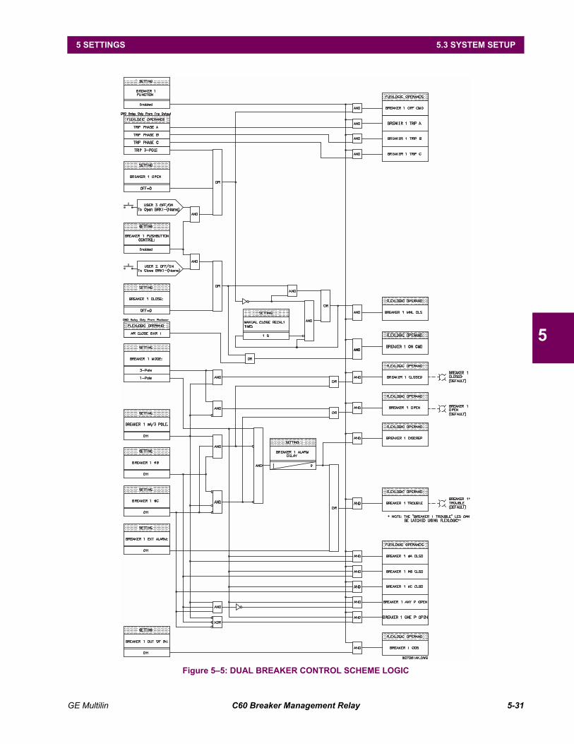
GE Multilin C60 Breaker Management Relay 5-31
5 SETTINGS 5.3 SYSTEM SETUP
5
Figure 55: DUAL BREAKER CONTROL SCHEME LOGIC
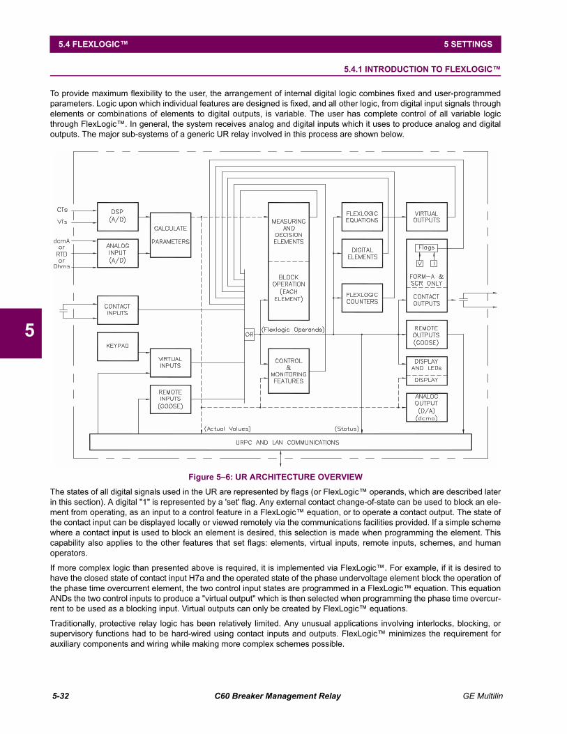
5-32 C60 Breaker Management Relay GE Multilin
5.4 FLEXLOGIC 5 SETTINGS
5
5.4 FLEXLOGIC 5.4.1 INTRODUCTION TO FLEXLOGIC
To provide maximum flexibility to the user, the arrangement of internal digital logic combines fixed and user-programmedparameters. Logic upon which individual features are designed is fixed, and all other logic, from digital input signals throughelements or combinations of elements to digital outputs, is variable. The user has complete control of all variable logicthrough FlexLogic. In general, the system receives analog and digital inputs which it uses to produce analog and digitaloutputs. The major sub-systems of a generic UR relay involved in this process are shown below.
Figure 56: UR ARCHITECTURE OVERVIEW
The states of all digital signals used in the UR are represented by flags (or FlexLogic operands, which are described laterin this section). A digital "1" is represented by a 'set' flag. Any external contact change-of-state can be used to block an ele-ment from operating, as an input to a control feature in a FlexLogic equation, or to operate a contact output. The state ofthe contact input can be displayed locally or viewed remotely via the communications facilities provided. If a simple schemewhere a contact input is used to block an element is desired, this selection is made when programming the element. Thiscapability also applies to the other features that set flags: elements, virtual inputs, remote inputs, schemes, and humanoperators.
If more complex logic than presented above is required, it is implemented via FlexLogic. For example, if it is desired tohave the closed state of contact input H7a and the operated state of the phase undervoltage element block the operation ofthe phase time overcurrent element, the two control input states are programmed in a FlexLogic equation. This equationANDs the two control inputs to produce a "virtual output" which is then selected when programming the phase time overcur-rent to be used as a blocking input. Virtual outputs can only be created by FlexLogic equations.
Traditionally, protective relay logic has been relatively limited. Any unusual applications involving interlocks, blocking, orsupervisory functions had to be hard-wired using contact inputs and outputs. FlexLogic minimizes the requirement forauxiliary components and wiring while making more complex schemes possible.
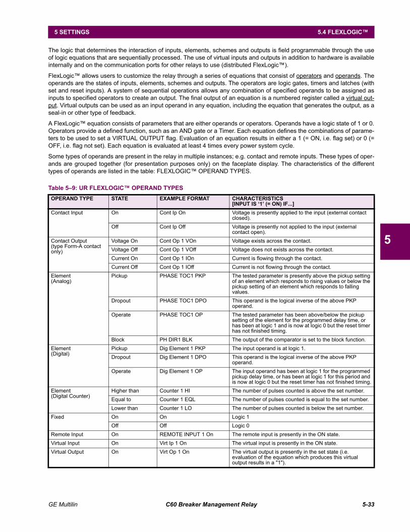
GE Multilin C60 Breaker Management Relay 5-33
5 SETTINGS 5.4 FLEXLOGIC
5
The logic that determines the interaction of inputs, elements, schemes and outputs is field programmable through the useof logic equations that are sequentially processed. The use of virtual inputs and outputs in addition to hardware is availableinternally and on the communication ports for other relays to use (distributed FlexLogic).
FlexLogic allows users to customize the relay through a series of equations that consist of operators and operands. Theoperands are the states of inputs, elements, schemes and outputs. The operators are logic gates, timers and latches (withset and reset inputs). A system of sequential operations allows any combination of specified operands to be assigned asinputs to specified operators to create an output. The final output of an equation is a numbered register called a virtual out-put. Virtual outputs can be used as an input operand in any equation, including the equation that generates the output, as aseal-in or other type of feedback.
A FlexLogic equation consists of parameters that are either operands or operators. Operands have a logic state of 1 or 0.Operators provide a defined function, such as an AND gate or a Timer. Each equation defines the combinations of parame-ters to be used to set a VIRTUAL OUTPUT flag. Evaluation of an equation results in either a 1 (= ON, i.e. flag set) or 0 (=OFF, i.e. flag not set). Each equation is evaluated at least 4 times every power system cycle.
Some types of operands are present in the relay in multiple instances; e.g. contact and remote inputs. These types of oper-ands are grouped together (for presentation purposes only) on the faceplate display. The characteristics of the differenttypes of operands are listed in the table: FLEXLOGIC OPERAND TYPES.
Table 59: UR FLEXLOGIC OPERAND TYPES OPERAND TYPE STATE EXAMPLE FORMAT CHARACTERISTICS
[INPUT IS 1 (= ON) IF...]Contact Input On Cont Ip On Voltage is presently applied to the input (external contact
closed).Off Cont Ip Off Voltage is presently not applied to the input (external
contact open).Contact Output(type Form-A contact only)
Voltage On Cont Op 1 VOn Voltage exists across the contact.Voltage Off Cont Op 1 VOff Voltage does not exists across the contact.Current On Cont Op 1 IOn Current is flowing through the contact.Current Off Cont Op 1 IOff Current is not flowing through the contact.
Element(Analog)
Pickup PHASE TOC1 PKP The tested parameter is presently above the pickup setting of an element which responds to rising values or below the pickup setting of an element which responds to falling values.
Dropout PHASE TOC1 DPO This operand is the logical inverse of the above PKP operand.
Operate PHASE TOC1 OP The tested parameter has been above/below the pickup setting of the element for the programmed delay time, or has been at logic 1 and is now at logic 0 but the reset timer has not finished timing.
Block PH DIR1 BLK The output of the comparator is set to the block function.Element(Digital)
Pickup Dig Element 1 PKP The input operand is at logic 1.Dropout Dig Element 1 DPO This operand is the logical inverse of the above PKP
operand.Operate Dig Element 1 OP The input operand has been at logic 1 for the programmed
pickup delay time, or has been at logic 1 for this period and is now at logic 0 but the reset timer has not finished timing.
Element(Digital Counter)
Higher than Counter 1 HI The number of pulses counted is above the set number.Equal to Counter 1 EQL The number of pulses counted is equal to the set number.Lower than Counter 1 LO The number of pulses counted is below the set number.
Fixed On On Logic 1Off Off Logic 0
Remote Input On REMOTE INPUT 1 On The remote input is presently in the ON state.Virtual Input On Virt Ip 1 On The virtual input is presently in the ON state.Virtual Output On Virt Op 1 On The virtual output is presently in the set state (i.e.
evaluation of the equation which produces this virtual output results in a "1").
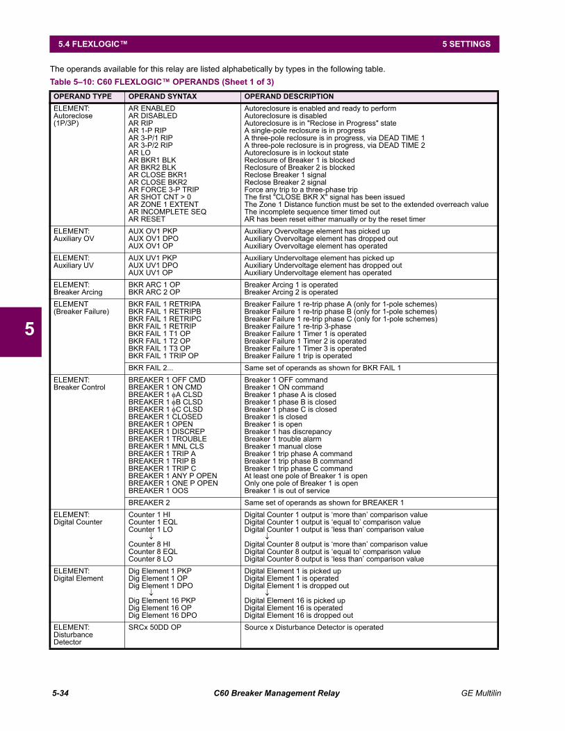
5-34 C60 Breaker Management Relay GE Multilin
5.4 FLEXLOGIC 5 SETTINGS
5
The operands available for this relay are listed alphabetically by types in the following table.Table 510: C60 FLEXLOGIC OPERANDS (Sheet 1 of 3)OPERAND TYPE OPERAND SYNTAX OPERAND DESCRIPTIONELEMENT:Autoreclose(1P/3P)
AR ENABLEDAR DISABLEDAR RIPAR 1-P RIPAR 3-P/1 RIPAR 3-P/2 RIPAR LOAR BKR1 BLKAR BKR2 BLKAR CLOSE BKR1AR CLOSE BKR2AR FORCE 3-P TRIPAR SHOT CNT > 0AR ZONE 1 EXTENTAR INCOMPLETE SEQAR RESET
Autoreclosure is enabled and ready to performAutoreclosure is disabledAutoreclosure is in "Reclose in Progress" stateA single-pole reclosure is in progressA three-pole reclosure is in progress, via DEAD TIME 1A three-pole reclosure is in progress, via DEAD TIME 2Autoreclosure is in lockout stateReclosure of Breaker 1 is blockedReclosure of Breaker 2 is blockedReclose Breaker 1 signalReclose Breaker 2 signalForce any trip to a three-phase tripThe first "CLOSE BKR X" signal has been issuedThe Zone 1 Distance function must be set to the extended overreach valueThe incomplete sequence timer timed outAR has been reset either manually or by the reset timer
ELEMENT:Auxiliary OV
AUX OV1 PKPAUX OV1 DPOAUX OV1 OP
Auxiliary Overvoltage element has picked upAuxiliary Overvoltage element has dropped outAuxiliary Overvoltage element has operated
ELEMENT:Auxiliary UV
AUX UV1 PKPAUX UV1 DPOAUX UV1 OP
Auxiliary Undervoltage element has picked upAuxiliary Undervoltage element has dropped outAuxiliary Undervoltage element has operated
ELEMENT:Breaker Arcing
BKR ARC 1 OPBKR ARC 2 OP
Breaker Arcing 1 is operatedBreaker Arcing 2 is operated
ELEMENT(Breaker Failure)
BKR FAIL 1 RETRIPABKR FAIL 1 RETRIPBBKR FAIL 1 RETRIPCBKR FAIL 1 RETRIPBKR FAIL 1 T1 OPBKR FAIL 1 T2 OPBKR FAIL 1 T3 OPBKR FAIL 1 TRIP OP
Breaker Failure 1 re-trip phase A (only for 1-pole schemes)Breaker Failure 1 re-trip phase B (only for 1-pole schemes)Breaker Failure 1 re-trip phase C (only for 1-pole schemes)Breaker Failure 1 re-trip 3-phaseBreaker Failure 1 Timer 1 is operatedBreaker Failure 1 Timer 2 is operatedBreaker Failure 1 Timer 3 is operatedBreaker Failure 1 trip is operated
BKR FAIL 2... Same set of operands as shown for BKR FAIL 1 ELEMENT:Breaker Control
BREAKER 1 OFF CMDBREAKER 1 ON CMDBREAKER 1 φA CLSDBREAKER 1 φB CLSDBREAKER 1 φC CLSDBREAKER 1 CLOSEDBREAKER 1 OPENBREAKER 1 DISCREPBREAKER 1 TROUBLEBREAKER 1 MNL CLSBREAKER 1 TRIP ABREAKER 1 TRIP BBREAKER 1 TRIP CBREAKER 1 ANY P OPENBREAKER 1 ONE P OPENBREAKER 1 OOS
Breaker 1 OFF commandBreaker 1 ON commandBreaker 1 phase A is closedBreaker 1 phase B is closedBreaker 1 phase C is closedBreaker 1 is closedBreaker 1 is openBreaker 1 has discrepancyBreaker 1 trouble alarmBreaker 1 manual closeBreaker 1 trip phase A commandBreaker 1 trip phase B commandBreaker 1 trip phase C commandAt least one pole of Breaker 1 is openOnly one pole of Breaker 1 is openBreaker 1 is out of service
BREAKER 2 Same set of operands as shown for BREAKER 1ELEMENT:Digital Counter
Counter 1 HICounter 1 EQLCounter 1 LO
↓Counter 8 HICounter 8 EQLCounter 8 LO
Digital Counter 1 output is more than comparison valueDigital Counter 1 output is equal to comparison valueDigital Counter 1 output is less than comparison value
↓Digital Counter 8 output is more than comparison valueDigital Counter 8 output is equal to comparison valueDigital Counter 8 output is less than comparison value
ELEMENT:Digital Element
Dig Element 1 PKPDig Element 1 OPDig Element 1 DPO
↓Dig Element 16 PKPDig Element 16 OPDig Element 16 DPO
Digital Element 1 is picked upDigital Element 1 is operatedDigital Element 1 is dropped out
↓Digital Element 16 is picked upDigital Element 16 is operatedDigital Element 16 is dropped out
ELEMENT:Disturbance Detector
SRCx 50DD OP Source x Disturbance Detector is operated
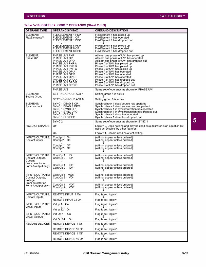
GE Multilin C60 Breaker Management Relay 5-35
5 SETTINGS 5.4 FLEXLOGIC
5
ELEMENT:FlexElements
FLEXELEMENT 1 PKPFLEXELEMENT 1 OPFLEXELEMENT 1 DPO
↓FLEXELEMENT 8 PKPFLEXELEMENT 8 OPFLEXELEMENT 8 DPO
FlexElement 1 has picked upFlexElement 1 has operatedFlexElement 1 has dropped out
↓FlexElement 8 has picked upFlexElement 8 has operatedFlexElement 8 has dropped out
ELEMENT:Phase UV
PHASE UV1 PKPPHASE UV1 OPPHASE UV1 DPOPHASE UV1 PKP APHASE UV1 PKP BPHASE UV1 PKP CPHASE UV1 OP APHASE UV1 OP BPHASE UV1 OP CPHASE UV1 DPO APHASE UV1 DPO BPHASE UV1 DPO C
At least one phase of UV1 has picked upAt least one phase of UV1 has operatedAt least one phase of UV1 has dropped outPhase A of UV1 has picked upPhase B of UV1 has picked upPhase C of UV1 has picked upPhase A of UV1 has operatedPhase B of UV1 has operatedPhase C of UV1 has operatedPhase A of UV1 has dropped outPhase B of UV1 has dropped outPhase C of UV1 has dropped out
PHASE UV2 Same set of operands as shown for PHASE UV1ELEMENT:Setting Group
SETTING GROUP ACT 1↓
SETTING GROUP ACT 8
Setting group 1 is active↓
Setting group 8 is activeELEMENT:Synchrocheck
SYNC 1 DEAD S OPSYNC 1 DEAD S DPOSYNC 1 SYNC OPSYNC 1 SYNC DPOSYNC 1 CLS OPSYNC 1 CLS DPO
Synchrocheck 1 dead source has operatedSynchrocheck 1 dead source has dropped outSynchrocheck 1 in synchronization has operatedSynchrocheck 1 in synchronization has dropped outSynchrocheck 1 close has operatedSynchrocheck 1 close has dropped out
SYNC 2 Same set of operands as shown for SYNC 1FIXED OPERANDS Off Logic = 0. Does nothing and may be used as a delimiter in an equation list;
used as Disable by other features.On Logic = 1. Can be used as a test setting.
INPUTS/OUTPUTS:Contact Inputs
Cont Ip 1 OnCont Ip 2 On
↓Cont Ip 1 OffCont Ip 2 Off
↓
(will not appear unless ordered)(will not appear unless ordered)
↓(will not appear unless ordered)(will not appear unless ordered)
↓
INPUTS/OUTPUTS:Contact Outputs, Current(from detector on Form-A output only)
Cont Op 1 IOnCont Op 2 IOn
↓
(will not appear unless ordered)(will not appear unless ordered)
↓
Cont Op 1 IOffCont Op 2 IOff
↓
(will not appear unless ordered)(will not appear unless ordered)
↓
INPUTS/OUTPUTS:Contact Outputs, Voltage(from detector on Form-A output only)
Cont Op 1 VOnCont Op 2 VOn
↓
(will not appear unless ordered)(will not appear unless ordered)
↓
Cont Op 1 VOffCont Op 2 VOff
↓
(will not appear unless ordered)(will not appear unless ordered)
↓
INPUTS/OUTPUTS:Remote Inputs
REMOTE INPUT 1 On↓
REMOTE INPUT 32 On
Flag is set, logic=1↓
Flag is set, logic=1INPUTS/OUTPUTS:Virtual Inputs
Virt Ip 1 On↓
Virt Ip 32 On
Flag is set, logic=1↓
Flag is set, logic=1INPUTS/OUTPUTS:Virtual Outputs
Virt Op 1 On↓
Virt Op 64 On
Flag is set, logic=1↓
Flag is set, logic=1REMOTE DEVICES REMOTE DEVICE 1 On
↓REMOTE DEVICE 16 On
Flag is set, logic=1↓
Flag is set, logic=1REMOTE DEVICE 1 Off
↓REMOTE DEVICE 16 Off
Flag is set, logic=1↓
Flag is set, logic=1
Table 510: C60 FLEXLOGIC OPERANDS (Sheet 2 of 3)OPERAND TYPE OPERAND SYNTAX OPERAND DESCRIPTION
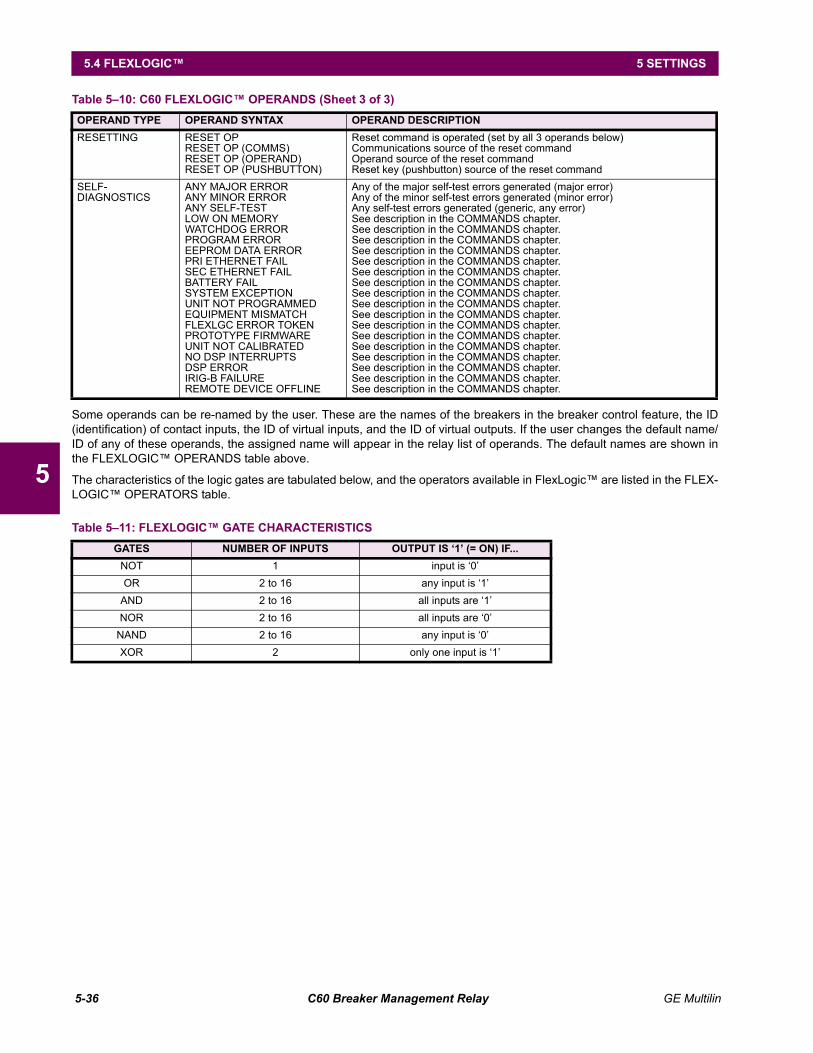
5-36 C60 Breaker Management Relay GE Multilin
5.4 FLEXLOGIC 5 SETTINGS
5
Some operands can be re-named by the user. These are the names of the breakers in the breaker control feature, the ID(identification) of contact inputs, the ID of virtual inputs, and the ID of virtual outputs. If the user changes the default name/ID of any of these operands, the assigned name will appear in the relay list of operands. The default names are shown inthe FLEXLOGIC OPERANDS table above.
The characteristics of the logic gates are tabulated below, and the operators available in FlexLogic are listed in the FLEX-LOGIC OPERATORS table.
RESETTING RESET OPRESET OP (COMMS)RESET OP (OPERAND)RESET OP (PUSHBUTTON)
Reset command is operated (set by all 3 operands below)Communications source of the reset commandOperand source of the reset commandReset key (pushbutton) source of the reset command
SELF-DIAGNOSTICS
ANY MAJOR ERRORANY MINOR ERRORANY SELF-TESTLOW ON MEMORYWATCHDOG ERRORPROGRAM ERROREEPROM DATA ERRORPRI ETHERNET FAILSEC ETHERNET FAILBATTERY FAILSYSTEM EXCEPTIONUNIT NOT PROGRAMMEDEQUIPMENT MISMATCHFLEXLGC ERROR TOKENPROTOTYPE FIRMWAREUNIT NOT CALIBRATEDNO DSP INTERRUPTSDSP ERRORIRIG-B FAILUREREMOTE DEVICE OFFLINE
Any of the major self-test errors generated (major error)Any of the minor self-test errors generated (minor error)Any self-test errors generated (generic, any error)See description in the COMMANDS chapter.See description in the COMMANDS chapter.See description in the COMMANDS chapter.See description in the COMMANDS chapter.See description in the COMMANDS chapter.See description in the COMMANDS chapter.See description in the COMMANDS chapter.See description in the COMMANDS chapter.See description in the COMMANDS chapter.See description in the COMMANDS chapter.See description in the COMMANDS chapter.See description in the COMMANDS chapter.See description in the COMMANDS chapter.See description in the COMMANDS chapter.See description in the COMMANDS chapter.See description in the COMMANDS chapter.See description in the COMMANDS chapter.
Table 511: FLEXLOGIC GATE CHARACTERISTICSGATES NUMBER OF INPUTS OUTPUT IS 1 (= ON) IF...
NOT 1 input is 0OR 2 to 16 any input is 1
AND 2 to 16 all inputs are 1NOR 2 to 16 all inputs are 0
NAND 2 to 16 any input is 0XOR 2 only one input is 1
Table 510: C60 FLEXLOGIC OPERANDS (Sheet 3 of 3)OPERAND TYPE OPERAND SYNTAX OPERAND DESCRIPTION
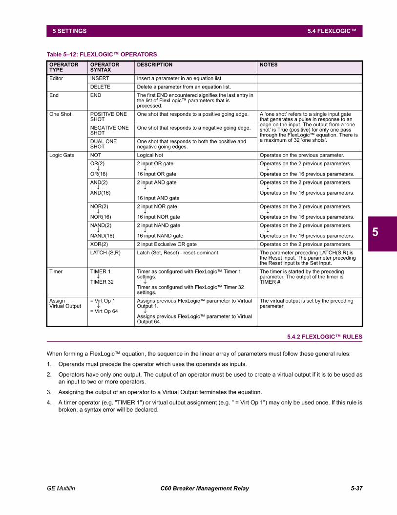
GE Multilin C60 Breaker Management Relay 5-37
5 SETTINGS 5.4 FLEXLOGIC
5
5.4.2 FLEXLOGIC RULES
When forming a FlexLogic equation, the sequence in the linear array of parameters must follow these general rules:
1. Operands must precede the operator which uses the operands as inputs.
2. Operators have only one output. The output of an operator must be used to create a virtual output if it is to be used asan input to two or more operators.
3. Assigning the output of an operator to a Virtual Output terminates the equation.
4. A timer operator (e.g. "TIMER 1") or virtual output assignment (e.g. " = Virt Op 1") may only be used once. If this rule isbroken, a syntax error will be declared.
Table 512: FLEXLOGIC OPERATORS OPERATORTYPE
OPERATORSYNTAX
DESCRIPTION NOTES
Editor INSERT Insert a parameter in an equation list.DELETE Delete a parameter from an equation list.
End END The first END encountered signifies the last entry in the list of FlexLogic parameters that is processed.
One Shot POSITIVE ONE SHOT
One shot that responds to a positive going edge. A one shot refers to a single input gate that generates a pulse in response to an edge on the input. The output from a one shot is True (positive) for only one pass through the FlexLogic equation. There is a maximum of 32 one shots.
NEGATIVE ONE SHOT
One shot that responds to a negative going edge.
DUAL ONE SHOT
One shot that responds to both the positive and negative going edges.
Logic Gate NOT Logical Not Operates on the previous parameter.OR(2)
↓OR(16)
2 input OR gate↓
16 input OR gate
Operates on the 2 previous parameters.↓
Operates on the 16 previous parameters.AND(2)
↓AND(16)
2 input AND gate↓
16 input AND gate
Operates on the 2 previous parameters.↓
Operates on the 16 previous parameters.
NOR(2)↓
NOR(16)
2 input NOR gate↓
16 input NOR gate
Operates on the 2 previous parameters.↓
Operates on the 16 previous parameters.NAND(2)
↓NAND(16)
2 input NAND gate↓
16 input NAND gate
Operates on the 2 previous parameters.↓
Operates on the 16 previous parameters.XOR(2) 2 input Exclusive OR gate Operates on the 2 previous parameters.LATCH (S,R) Latch (Set, Reset) - reset-dominant The parameter preceding LATCH(S,R) is
the Reset input. The parameter preceding the Reset input is the Set input.
Timer TIMER 1↓
TIMER 32
Timer as configured with FlexLogic Timer 1 settings.
↓Timer as configured with FlexLogic Timer 32 settings.
The timer is started by the preceding parameter. The output of the timer is TIMER #.
Assign Virtual Output
= Virt Op 1↓
= Virt Op 64
Assigns previous FlexLogic parameter to Virtual Output 1.
↓Assigns previous FlexLogic parameter to Virtual Output 64.
The virtual output is set by the preceding parameter
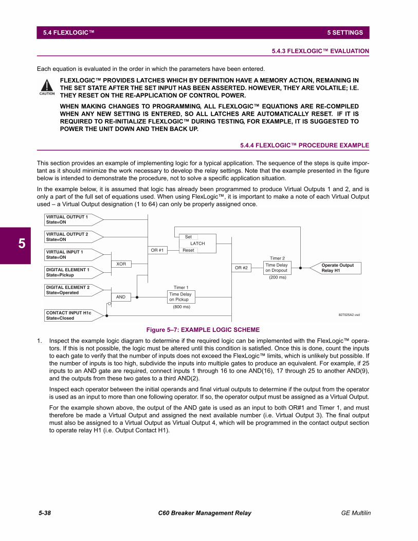
5-38 C60 Breaker Management Relay GE Multilin
5.4 FLEXLOGIC 5 SETTINGS
5
5.4.3 FLEXLOGIC EVALUATION
Each equation is evaluated in the order in which the parameters have been entered.
5.4.4 FLEXLOGIC PROCEDURE EXAMPLE
This section provides an example of implementing logic for a typical application. The sequence of the steps is quite impor-tant as it should minimize the work necessary to develop the relay settings. Note that the example presented in the figurebelow is intended to demonstrate the procedure, not to solve a specific application situation.
In the example below, it is assumed that logic has already been programmed to produce Virtual Outputs 1 and 2, and isonly a part of the full set of equations used. When using FlexLogic, it is important to make a note of each Virtual Outputused a Virtual Output designation (1 to 64) can only be properly assigned once.
Figure 57: EXAMPLE LOGIC SCHEME
1. Inspect the example logic diagram to determine if the required logic can be implemented with the FlexLogic opera-tors. If this is not possible, the logic must be altered until this condition is satisfied. Once this is done, count the inputsto each gate to verify that the number of inputs does not exceed the FlexLogic limits, which is unlikely but possible. Ifthe number of inputs is too high, subdivide the inputs into multiple gates to produce an equivalent. For example, if 25inputs to an AND gate are required, connect inputs 1 through 16 to one AND(16), 17 through 25 to another AND(9),and the outputs from these two gates to a third AND(2).
Inspect each operator between the initial operands and final virtual outputs to determine if the output from the operatoris used as an input to more than one following operator. If so, the operator output must be assigned as a Virtual Output.
For the example shown above, the output of the AND gate is used as an input to both OR#1 and Timer 1, and musttherefore be made a Virtual Output and assigned the next available number (i.e. Virtual Output 3). The final outputmust also be assigned to a Virtual Output as Virtual Output 4, which will be programmed in the contact output sectionto operate relay H1 (i.e. Output Contact H1).
FLEXLOGIC PROVIDES LATCHES WHICH BY DEFINITION HAVE A MEMORY ACTION, REMAINING INTHE SET STATE AFTER THE SET INPUT HAS BEEN ASSERTED. HOWEVER, THEY ARE VOLATILE; I.E.THEY RESET ON THE RE-APPLICATION OF CONTROL POWER.
WHEN MAKING CHANGES TO PROGRAMMING, ALL FLEXLOGIC EQUATIONS ARE RE-COMPILEDWHEN ANY NEW SETTING IS ENTERED, SO ALL LATCHES ARE AUTOMATICALLY RESET. IF IT ISREQUIRED TO RE-INITIALIZE FLEXLOGIC DURING TESTING, FOR EXAMPLE, IT IS SUGGESTED TOPOWER THE UNIT DOWN AND THEN BACK UP.
CAUTION
LATCH
CONTACT INPUT H1cState=Closed
XOR
AND
Reset
SetVIRTUAL OUTPUT 2State=ON
VIRTUAL INPUT 1State=ON
DIGITAL ELEMENT 1State=Pickup
DIGITAL ELEMENT 2State=Operated
OR #2Operate OutputRelay H1
OR #1
(800 ms)
Timer 1
Time Delayon Pickup
(200 ms)
Timer 2
Time Delayon Dropout
VIRTUAL OUTPUT 1State=ON
827025A2.vsd
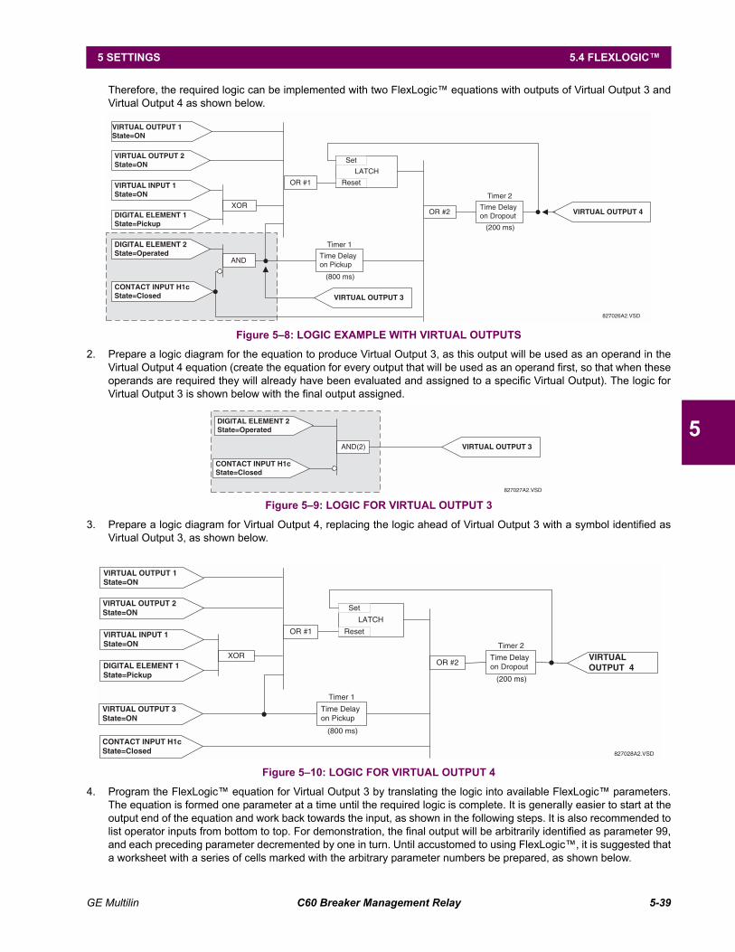
GE Multilin C60 Breaker Management Relay 5-39
5 SETTINGS 5.4 FLEXLOGIC
5
Therefore, the required logic can be implemented with two FlexLogic equations with outputs of Virtual Output 3 andVirtual Output 4 as shown below.
Figure 58: LOGIC EXAMPLE WITH VIRTUAL OUTPUTS
2. Prepare a logic diagram for the equation to produce Virtual Output 3, as this output will be used as an operand in theVirtual Output 4 equation (create the equation for every output that will be used as an operand first, so that when theseoperands are required they will already have been evaluated and assigned to a specific Virtual Output). The logic forVirtual Output 3 is shown below with the final output assigned.
Figure 59: LOGIC FOR VIRTUAL OUTPUT 3
3. Prepare a logic diagram for Virtual Output 4, replacing the logic ahead of Virtual Output 3 with a symbol identified asVirtual Output 3, as shown below.
Figure 510: LOGIC FOR VIRTUAL OUTPUT 4
4. Program the FlexLogic equation for Virtual Output 3 by translating the logic into available FlexLogic parameters.The equation is formed one parameter at a time until the required logic is complete. It is generally easier to start at theoutput end of the equation and work back towards the input, as shown in the following steps. It is also recommended tolist operator inputs from bottom to top. For demonstration, the final output will be arbitrarily identified as parameter 99,and each preceding parameter decremented by one in turn. Until accustomed to using FlexLogic, it is suggested thata worksheet with a series of cells marked with the arbitrary parameter numbers be prepared, as shown below.
LATCH
CONTACT INPUT H1cState=Closed
XOR
AND
Reset
SetVIRTUAL OUTPUT 2State=ON
VIRTUAL INPUT 1State=ON
DIGITAL ELEMENT 1State=Pickup
DIGITAL ELEMENT 2State=Operated
OR #2 VIRTUAL OUTPUT 4
OR #1
(800 ms)
Timer 1
Time Delayon Pickup
(200 ms)
Timer 2
Time Delayon Dropout
VIRTUAL OUTPUT 1State=ON
827026A2.VSD
VIRTUAL OUTPUT 3
CONTACT INPUT H1cState=Closed
AND(2)
DIGITAL ELEMENT 2State=Operated
VIRTUAL OUTPUT 3
827027A2.VSD
LATCH
CONTACT INPUT H1cState=Closed
XOR
Reset
SetVIRTUAL OUTPUT 2State=ON
VIRTUAL INPUT 1State=ON
DIGITAL ELEMENT 1State=Pickup
OR #2VIRTUALOUTPUT 4
OR #1
(800 ms)
Timer 1
Time Delayon Pickup
(200 ms)
Timer 2
Time Delayon Dropout
VIRTUAL OUTPUT 3State=ON
VIRTUAL OUTPUT 1State=ON
827028A2.VSD
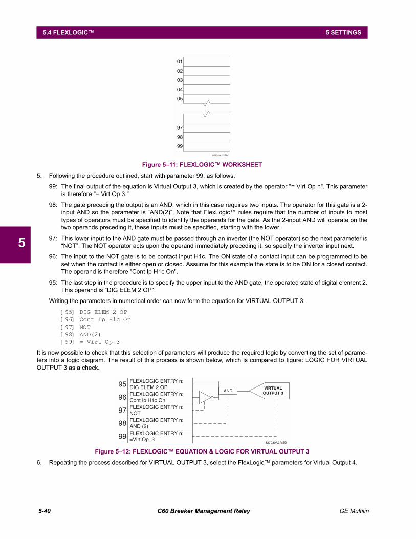
5-40 C60 Breaker Management Relay GE Multilin
5.4 FLEXLOGIC 5 SETTINGS
5
Figure 511: FLEXLOGIC WORKSHEET
5. Following the procedure outlined, start with parameter 99, as follows:
99: The final output of the equation is Virtual Output 3, which is created by the operator "= Virt Op n". This parameteris therefore "= Virt Op 3."
98: The gate preceding the output is an AND, which in this case requires two inputs. The operator for this gate is a 2-input AND so the parameter is AND(2). Note that FlexLogic rules require that the number of inputs to mosttypes of operators must be specified to identify the operands for the gate. As the 2-input AND will operate on thetwo operands preceding it, these inputs must be specified, starting with the lower.
97: This lower input to the AND gate must be passed through an inverter (the NOT operator) so the next parameter isNOT. The NOT operator acts upon the operand immediately preceding it, so specify the inverter input next.
96: The input to the NOT gate is to be contact input H1c. The ON state of a contact input can be programmed to beset when the contact is either open or closed. Assume for this example the state is to be ON for a closed contact.The operand is therefore "Cont Ip H1c On".
95: The last step in the procedure is to specify the upper input to the AND gate, the operated state of digital element 2.This operand is "DIG ELEM 2 OP".
Writing the parameters in numerical order can now form the equation for VIRTUAL OUTPUT 3:
[95] DIG ELEM 2 OP[96] Cont Ip H1c On[97] NOT[98] AND(2)[99] = Virt Op 3
It is now possible to check that this selection of parameters will produce the required logic by converting the set of parame-ters into a logic diagram. The result of this process is shown below, which is compared to figure: LOGIC FOR VIRTUALOUTPUT 3 as a check.
Figure 512: FLEXLOGIC EQUATION & LOGIC FOR VIRTUAL OUTPUT 3
6. Repeating the process described for VIRTUAL OUTPUT 3, select the FlexLogic parameters for Virtual Output 4.
01
02
03
04
05
97
98
99
.....
827029A1.VSD
FLEXLOGIC ENTRY n:NOTFLEXLOGIC ENTRY n:AND (2)FLEXLOGIC ENTRY n:=Virt Op 3
97
98
99
FLEXLOGIC ENTRY n:DIG ELEM 2 OPFLEXLOGIC ENTRY n:Cont Ip H1c On
95
96AND
VIRTUALOUTPUT 3
827030A2.VSD
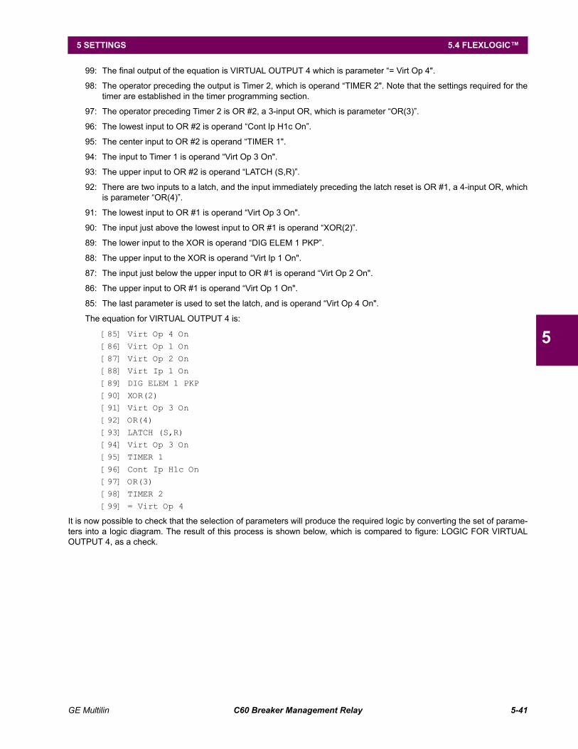
GE Multilin C60 Breaker Management Relay 5-41
5 SETTINGS 5.4 FLEXLOGIC
5
99: The final output of the equation is VIRTUAL OUTPUT 4 which is parameter = Virt Op 4".
98: The operator preceding the output is Timer 2, which is operand TIMER 2". Note that the settings required for thetimer are established in the timer programming section.
97: The operator preceding Timer 2 is OR #2, a 3-input OR, which is parameter OR(3).
96: The lowest input to OR #2 is operand Cont Ip H1c On.
95: The center input to OR #2 is operand TIMER 1".
94: The input to Timer 1 is operand Virt Op 3 On".
93: The upper input to OR #2 is operand LATCH (S,R).
92: There are two inputs to a latch, and the input immediately preceding the latch reset is OR #1, a 4-input OR, whichis parameter OR(4).
91: The lowest input to OR #1 is operand Virt Op 3 On".
90: The input just above the lowest input to OR #1 is operand XOR(2).
89: The lower input to the XOR is operand DIG ELEM 1 PKP.
88: The upper input to the XOR is operand Virt Ip 1 On".
87: The input just below the upper input to OR #1 is operand Virt Op 2 On".
86: The upper input to OR #1 is operand Virt Op 1 On".
85: The last parameter is used to set the latch, and is operand Virt Op 4 On".
The equation for VIRTUAL OUTPUT 4 is:
[85] Virt Op 4 On
[86] Virt Op 1 On
[87] Virt Op 2 On[88] Virt Ip 1 On
[89] DIG ELEM 1 PKP
[90] XOR(2)[91] Virt Op 3 On
[92] OR(4)
[93] LATCH (S,R)[94] Virt Op 3 On
[95] TIMER 1
[96] Cont Ip H1c On[97] OR(3)
[98] TIMER 2
[99] = Virt Op 4
It is now possible to check that the selection of parameters will produce the required logic by converting the set of parame-ters into a logic diagram. The result of this process is shown below, which is compared to figure: LOGIC FOR VIRTUALOUTPUT 4, as a check.
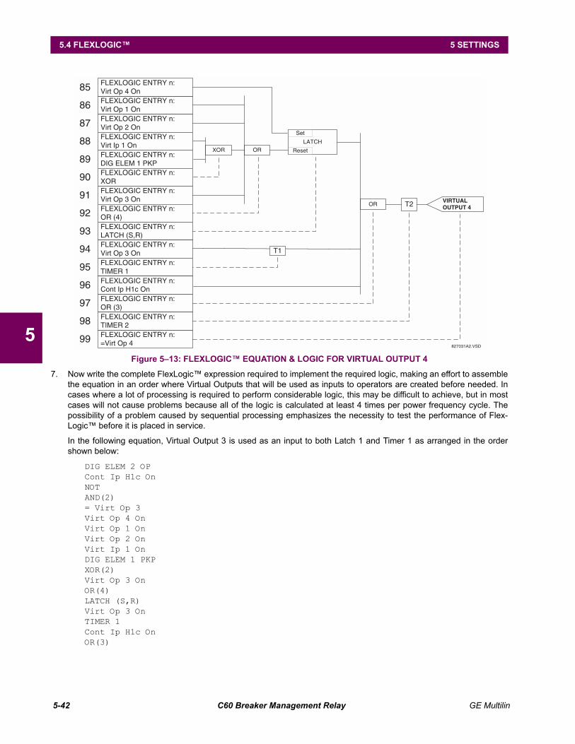
5-42 C60 Breaker Management Relay GE Multilin
5.4 FLEXLOGIC 5 SETTINGS
5Figure 513: FLEXLOGIC EQUATION & LOGIC FOR VIRTUAL OUTPUT 4
7. Now write the complete FlexLogic expression required to implement the required logic, making an effort to assemblethe equation in an order where Virtual Outputs that will be used as inputs to operators are created before needed. Incases where a lot of processing is required to perform considerable logic, this may be difficult to achieve, but in mostcases will not cause problems because all of the logic is calculated at least 4 times per power frequency cycle. Thepossibility of a problem caused by sequential processing emphasizes the necessity to test the performance of Flex-Logic before it is placed in service.
In the following equation, Virtual Output 3 is used as an input to both Latch 1 and Timer 1 as arranged in the ordershown below:
DIG ELEM 2 OPCont Ip H1c OnNOTAND(2)= Virt Op 3Virt Op 4 OnVirt Op 1 OnVirt Op 2 OnVirt Ip 1 OnDIG ELEM 1 PKPXOR(2)Virt Op 3 OnOR(4)LATCH (S,R)Virt Op 3 OnTIMER 1Cont Ip H1c OnOR(3)
FLEXLOGIC ENTRY n:Virt Op 3 OnFLEXLOGIC ENTRY n:OR (4)FLEXLOGIC ENTRY n:LATCH (S,R)
91
92
93
FLEXLOGIC ENTRY n:DIG ELEM 1 PKPFLEXLOGIC ENTRY n:XOR
89
90
XOR
FLEXLOGIC ENTRY n:Virt Op 1 OnFLEXLOGIC ENTRY n:Virt Op 2 OnFLEXLOGIC ENTRY n:Virt Ip 1 On
86
87
88
FLEXLOGIC ENTRY n:Virt Op 4 On85
FLEXLOGIC ENTRY n:=Virt Op 499
FLEXLOGIC ENTRY n:OR (3)FLEXLOGIC ENTRY n:TIMER 2
96
97
98
FLEXLOGIC ENTRY n:Virt Op 3 OnFLEXLOGIC ENTRY n:TIMER 1
94
95
LATCH
Reset
Set
OR
OR
T1
T2 VIRTUALOUTPUT 4
827031A2.VSD
FLEXLOGIC ENTRY n:Cont Ip H1c On
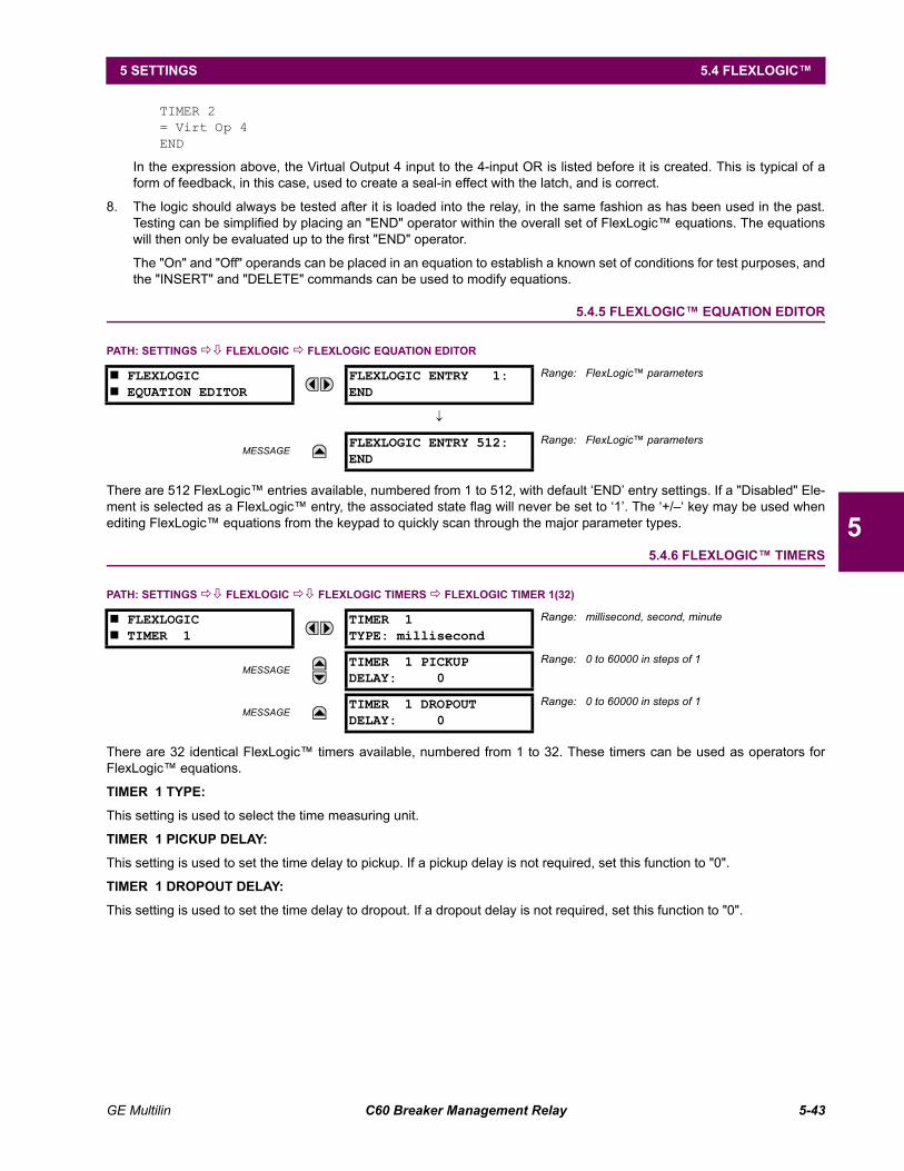
GE Multilin C60 Breaker Management Relay 5-43
5 SETTINGS 5.4 FLEXLOGIC
5
TIMER 2= Virt Op 4END
In the expression above, the Virtual Output 4 input to the 4-input OR is listed before it is created. This is typical of aform of feedback, in this case, used to create a seal-in effect with the latch, and is correct.
8. The logic should always be tested after it is loaded into the relay, in the same fashion as has been used in the past.Testing can be simplified by placing an "END" operator within the overall set of FlexLogic equations. The equationswill then only be evaluated up to the first "END" operator.
The "On" and "Off" operands can be placed in an equation to establish a known set of conditions for test purposes, andthe "INSERT" and "DELETE" commands can be used to modify equations.
5.4.5 FLEXLOGIC EQUATION EDITOR
PATH: SETTINGS !" FLEXLOGIC ! FLEXLOGIC EQUATION EDITOR
There are 512 FlexLogic entries available, numbered from 1 to 512, with default END entry settings. If a "Disabled" Ele-ment is selected as a FlexLogic entry, the associated state flag will never be set to 1. The +/ key may be used whenediting FlexLogic equations from the keypad to quickly scan through the major parameter types.
5.4.6 FLEXLOGIC TIMERS
PATH: SETTINGS !" FLEXLOGIC !" FLEXLOGIC TIMERS ! FLEXLOGIC TIMER 1(32)
There are 32 identical FlexLogic timers available, numbered from 1 to 32. These timers can be used as operators forFlexLogic equations.
TIMER 1 TYPE:
This setting is used to select the time measuring unit.
TIMER 1 PICKUP DELAY:
This setting is used to set the time delay to pickup. If a pickup delay is not required, set this function to "0".
TIMER 1 DROPOUT DELAY:
This setting is used to set the time delay to dropout. If a dropout delay is not required, set this function to "0".
# FLEXLOGIC# EQUATION EDITOR
FLEXLOGIC ENTRY 1:END
Range: FlexLogic parameters
↓
MESSAGEFLEXLOGIC ENTRY 512:END
Range: FlexLogic parameters
# FLEXLOGIC# TIMER 1
TIMER 1TYPE: millisecond
Range: millisecond, second, minute
MESSAGETIMER 1 PICKUPDELAY: 0
Range: 0 to 60000 in steps of 1
MESSAGETIMER 1 DROPOUTDELAY: 0
Range: 0 to 60000 in steps of 1

5-44 C60 Breaker Management Relay GE Multilin
5.4 FLEXLOGIC 5 SETTINGS
5
5.4.7 FLEXELEMENTS
PATH: SETTING !" FLEXLOGIC !" FLEXELEMENTS ! FLEXELEMENT 1(8)
A FlexElement is a universal comparator that can be used to monitor any analog actual value calculated by the relay or anet difference of any two analog actual values of the same type. The effective operating signal could be treated as a signednumber or its absolute value could be used as per user's choice.
The element can be programmed to respond either to a signal level or to a rate-of-change (delta) over a pre-defined periodof time. The output operand is asserted when the operating signal is higher than a threshold or lower than a threshold asper user's choice.
# FLEXELEMENT 1#
FLEXELEMENT 1FUNCTION: Disabled
Range: Disabled, Enabled
MESSAGEFLEXELEMENT 1 NAME:FxE1
Range: up to 6 alphanumeric characters
MESSAGEFLEXELEMENT 1 +INOff
Range: Off, any analog actual value parameter
MESSAGEFLEXELEMENT 1 -INOff
Range: Off, any analog actual value parameter
MESSAGEFLEXELEMENT 1 INPUTMODE: Signed
Range: Signed, Absolute
MESSAGEFLEXELEMENT 1 COMPMODE: Level
Range: Level, Delta
MESSAGEFLEXELEMENT 1DIRECTION: Over
Range: Over, Under
MESSAGEFLEXELEMENT 1PICKUP: 1.000 pu
Range: 90.000 to 90.000 pu in steps of 0.001
MESSAGEFLEXELEMENT 1HYSTERESIS: 3.0%
Range: 0.1 to 50.0% in steps of 0.1
MESSAGEFLEXELEMENT 1 dtUNIT: milliseconds
Range: milliseconds, seconds, minutes
MESSAGEFLEXELEMENT 1 dt:20
Range: 20 to 86400 in steps of 1
MESSAGEFLEXELEMENT 1 PKPDELAY: 0.000 s
Range: 0.000 to 65.535 sec. in steps of 0.001
MESSAGEFLEXELEMENT 1 RSTDELAY: 0.000 s
Range: 0.000 to 65.535 sec. in steps of 0.001
MESSAGEFLEXELEMENT 1BLOCK: Off
Range: FlexLogic operand
MESSAGEFLEXELEMENT 1TARGET: Self-reset
Range: Self-reset, Latched, Disabled
MESSAGEFLEXELEMENT 1EVENTS: Disabled
Range: Disabled, Enabled
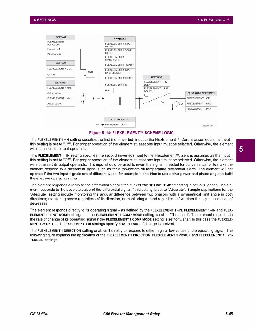
GE Multilin C60 Breaker Management Relay 5-45
5 SETTINGS 5.4 FLEXLOGIC
5
Figure 514: FLEXELEMENT SCHEME LOGIC
The FLEXELEMENT 1 +IN setting specifies the first (non-inverted) input to the FlexElement. Zero is assumed as the input ifthis setting is set to "Off". For proper operation of the element at least one input must be selected. Otherwise, the elementwill not assert its output operands.
This FLEXELEMENT 1 IN setting specifies the second (inverted) input to the FlexElement. Zero is assumed as the input ifthis setting is set to "Off". For proper operation of the element at least one input must be selected. Otherwise, the elementwill not assert its output operands. This input should be used to invert the signal if needed for convenience, or to make theelement respond to a differential signal such as for a top-bottom oil temperature differential alarm. The element will notoperate if the two input signals are of different types, for example if one tries to use active power and phase angle to buildthe effective operating signal.
The element responds directly to the differential signal if the FLEXELEMENT 1 INPUT MODE setting is set to "Signed". The ele-ment responds to the absolute value of the differential signal if this setting is set to "Absolute". Sample applications for the"Absolute" setting include monitoring the angular difference between two phasors with a symmetrical limit angle in bothdirections; monitoring power regardless of its direction, or monitoring a trend regardless of whether the signal increases ofdecreases.
The element responds directly to its operating signal as defined by the FLEXELEMENT 1 +IN, FLEXELEMENT 1 IN and FLEX-ELEMENT 1 INPUT MODE settings if the FLEXELEMENT 1 COMP MODE setting is set to "Threshold". The element responds tothe rate of change of its operating signal if the FLEXELEMENT 1 COMP MODE setting is set to "Delta". In this case the FLEXELE-MENT 1 dt UNIT and FLEXELEMENT 1 dt settings specify how the rate of change is derived.
The FLEXELEMENT 1 DIRECTION setting enables the relay to respond to either high or low values of the operating signal. Thefollowing figure explains the application of the FLEXELEMENT 1 DIRECTION, FLEXELEMENT 1 PICKUP and FLEXELEMENT 1 HYS-TERESIS settings.
842004A1.CDR
FLEXELEMENT 1
FUNCTION:
SETTING
Enabled = 1
SETTINGS
FLEXELEMENT 1 INPUT
MODE:
FLEXELEMENT 1 COMP
MODE:
FLEXELEMENT 1
DIRECTION:
FLEXELEMENT 1 PICKUP:
FLEXELEMENT 1 dt UNIT:
FLEXELEMENT 1 dt:
RUN
FLEXELEMENT 1 +IN:
SETTINGS
Actual Value FLEXLOGIC OPERANDS
FLEXELEMENT 1 DPO
FLEXELEMENT 1 OP
FLEXELEMENT 1 PKP
FLEXELEMENT 1 -IN:
Actual Value
+
-
FlexElement 1 OpSig
ACTUAL VALUE
Disabled = 0
FLEXELEMENT 1 BLK:
SETTING
Off = 0
AND
tPKP
tRST
SETTINGS
FLEXELEMENT 1 RST
DELAY:
FLEXELEMENT 1 PKP
DELAY:
FLEXELEMENT 1 INPUT
HYSTERESIS:
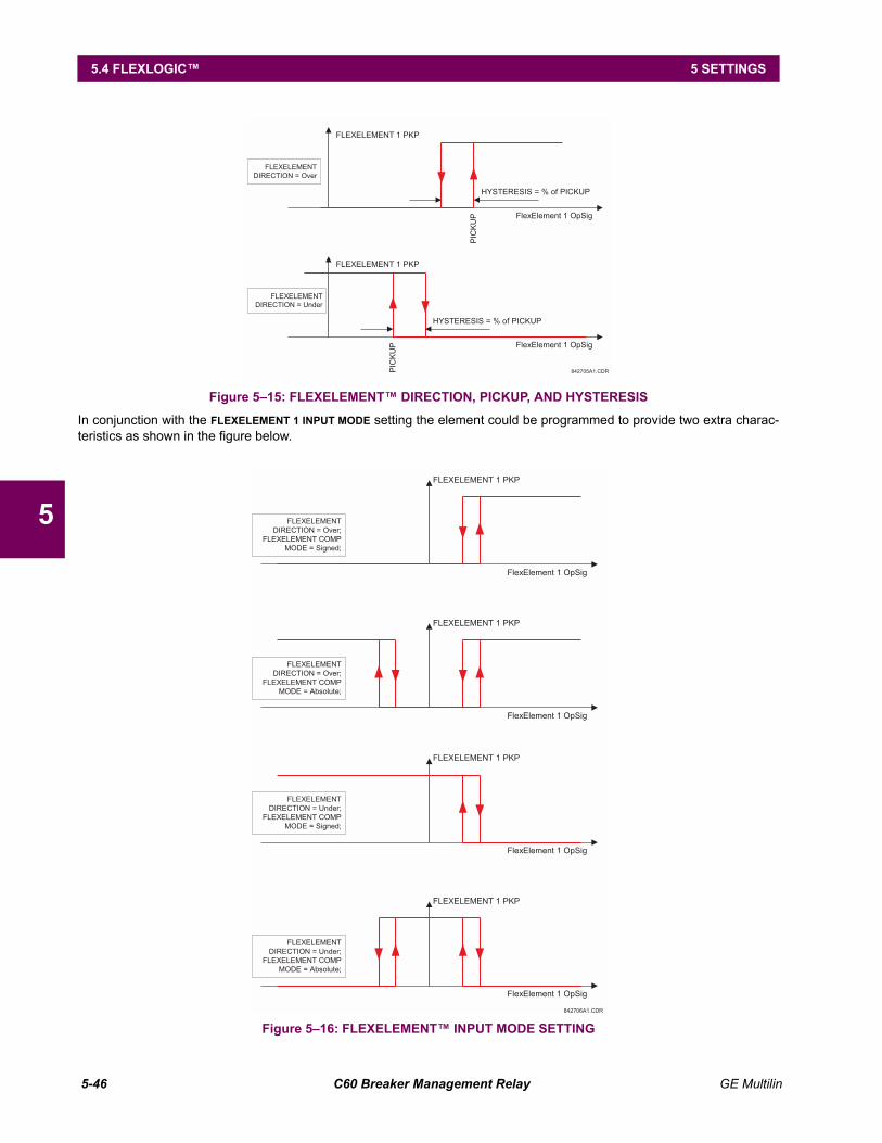
5-46 C60 Breaker Management Relay GE Multilin
5.4 FLEXLOGIC 5 SETTINGS
5
Figure 515: FLEXELEMENT DIRECTION, PICKUP, AND HYSTERESIS
In conjunction with the FLEXELEMENT 1 INPUT MODE setting the element could be programmed to provide two extra charac-teristics as shown in the figure below.
Figure 516: FLEXELEMENT INPUT MODE SETTING
FlexElement 1 OpSig
FLEXELEMENT 1 PKP
FLEXELEMENT
DIRECTION = Over
PIC
KU
P
HYSTERESIS = % of PICKUP
FlexElement 1 OpSig
FLEXELEMENT 1 PKP
FLEXELEMENT
DIRECTION = Under
PIC
KU
P
HYSTERESIS = % of PICKUP
842705A1.CDR
FlexElement 1 OpSig
FLEXELEMENT 1 PKP
FLEXELEMENT
DIRECTION = Over;
FLEXELEMENT COMP
MODE = Signed;
FlexElement 1 OpSig
FLEXELEMENT 1 PKP
FLEXELEMENT
DIRECTION = Over;
FLEXELEMENT COMP
MODE = Absolute;
FlexElement 1 OpSig
FLEXELEMENT 1 PKP
FLEXELEMENT
DIRECTION = Under;
FLEXELEMENT COMP
MODE = Signed;
FlexElement 1 OpSig
FLEXELEMENT 1 PKP
FLEXELEMENT
DIRECTION = Under;
FLEXELEMENT COMP
MODE = Absolute;
842706A1.CDR
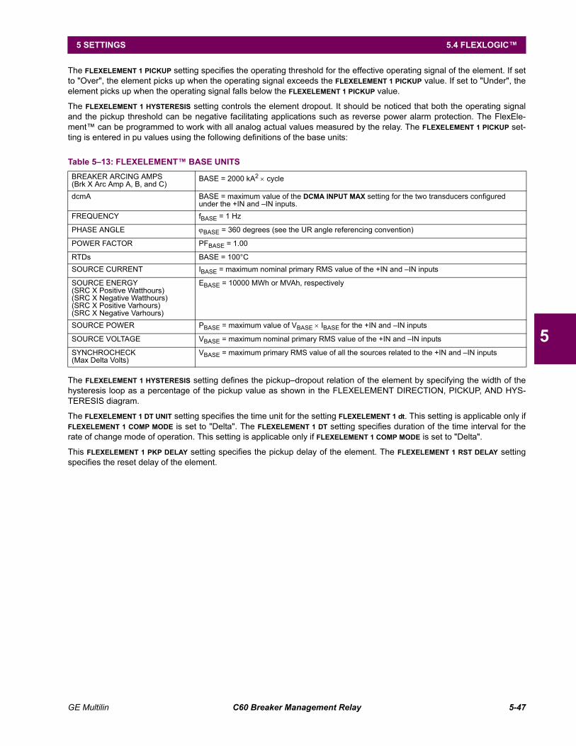
GE Multilin C60 Breaker Management Relay 5-47
5 SETTINGS 5.4 FLEXLOGIC
5
The FLEXELEMENT 1 PICKUP setting specifies the operating threshold for the effective operating signal of the element. If setto "Over", the element picks up when the operating signal exceeds the FLEXELEMENT 1 PICKUP value. If set to "Under", theelement picks up when the operating signal falls below the FLEXELEMENT 1 PICKUP value.
The FLEXELEMENT 1 HYSTERESIS setting controls the element dropout. It should be noticed that both the operating signaland the pickup threshold can be negative facilitating applications such as reverse power alarm protection. The FlexEle-ment can be programmed to work with all analog actual values measured by the relay. The FLEXELEMENT 1 PICKUP set-ting is entered in pu values using the following definitions of the base units:
The FLEXELEMENT 1 HYSTERESIS setting defines the pickupdropout relation of the element by specifying the width of thehysteresis loop as a percentage of the pickup value as shown in the FLEXELEMENT DIRECTION, PICKUP, AND HYS-TERESIS diagram.
The FLEXELEMENT 1 DT UNIT setting specifies the time unit for the setting FLEXELEMENT 1 dt. This setting is applicable only ifFLEXELEMENT 1 COMP MODE is set to "Delta". The FLEXELEMENT 1 DT setting specifies duration of the time interval for therate of change mode of operation. This setting is applicable only if FLEXELEMENT 1 COMP MODE is set to "Delta".
This FLEXELEMENT 1 PKP DELAY setting specifies the pickup delay of the element. The FLEXELEMENT 1 RST DELAY settingspecifies the reset delay of the element.
Table 513: FLEXELEMENT BASE UNITSBREAKER ARCING AMPS(Brk X Arc Amp A, B, and C)
BASE = 2000 kA2 × cycle
dcmA BASE = maximum value of the DCMA INPUT MAX setting for the two transducers configured under the +IN and IN inputs.
FREQUENCY fBASE = 1 Hz
PHASE ANGLE ϕBASE = 360 degrees (see the UR angle referencing convention)
POWER FACTOR PFBASE = 1.00
RTDs BASE = 100°CSOURCE CURRENT IBASE = maximum nominal primary RMS value of the +IN and IN inputs
SOURCE ENERGY(SRC X Positive Watthours)(SRC X Negative Watthours)(SRC X Positive Varhours)(SRC X Negative Varhours)
EBASE = 10000 MWh or MVAh, respectively
SOURCE POWER PBASE = maximum value of VBASE × IBASE for the +IN and IN inputs
SOURCE VOLTAGE VBASE = maximum nominal primary RMS value of the +IN and IN inputs
SYNCHROCHECK(Max Delta Volts)
VBASE = maximum primary RMS value of all the sources related to the +IN and IN inputs
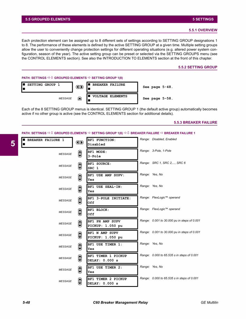
5-48 C60 Breaker Management Relay GE Multilin
5.5 GROUPED ELEMENTS 5 SETTINGS
5
5.5 GROUPED ELEMENTS 5.5.1 OVERVIEW
Each protection element can be assigned up to 8 different sets of settings according to SETTING GROUP designations 1to 8. The performance of these elements is defined by the active SETTING GROUP at a given time. Multiple setting groupsallow the user to conveniently change protection settings for different operating situations (e.g. altered power system con-figuration, season of the year). The active setting group can be preset or selected via the SETTING GROUPS menu (seethe CONTROL ELEMENTS section). See also the INTRODUCTION TO ELEMENTS section at the front of this chapter.
5.5.2 SETTING GROUP
PATH: SETTINGS !" GROUPED ELEMENTS ! SETTING GROUP 1(8)
Each of the 8 SETTING GROUP menus is identical. SETTING GROUP 1 (the default active group) automatically becomesactive if no other group is active (see the CONTROL ELEMENTS section for additional details).
5.5.3 BREAKER FAILURE
PATH: SETTINGS !" GROUPED ELEMENTS ! SETTING GROUP 1(8) !" BREAKER FAILURE ! BREAKER FAILURE 1
# SETTING GROUP 1#
# BREAKER FAILURE#
See page 5-48.
MESSAGE# VOLTAGE ELEMENTS#
See page 5-58.
# BREAKER FAILURE 1#
BF1 FUNCTION:Disabled
Range: Disabled, Enabled
MESSAGEBF1 MODE:3-Pole
Range: 3-Pole, 1-Pole
MESSAGEBF1 SOURCE:SRC 1
Range: SRC 1, SRC 2,..., SRC 6
MESSAGEBF1 USE AMP SUPV:Yes
Range: Yes, No
MESSAGEBF1 USE SEAL-IN:Yes
Range: Yes, No
MESSAGEBF1 3-POLE INITIATE:Off
Range: FlexLogic operand
MESSAGEBF1 BLOCK:Off
Range: FlexLogic operand
MESSAGEBF1 PH AMP SUPVPICKUP: 1.050 pu
Range: 0.001 to 30.000 pu in steps of 0.001
MESSAGEBF1 N AMP SUPVPICKUP: 1.050 pu
Range: 0.001 to 30.000 pu in steps of 0.001
MESSAGEBF1 USE TIMER 1:Yes
Range: Yes, No
MESSAGEBF1 TIMER 1 PICKUPDELAY: 0.000 s
Range: 0.000 to 65.535 s in steps of 0.001
MESSAGEBF1 USE TIMER 2:Yes
Range: Yes, No
MESSAGEBF1 TIMER 2 PICKUPDELAY: 0.000 s
Range: 0.000 to 65.535 s in steps of 0.001
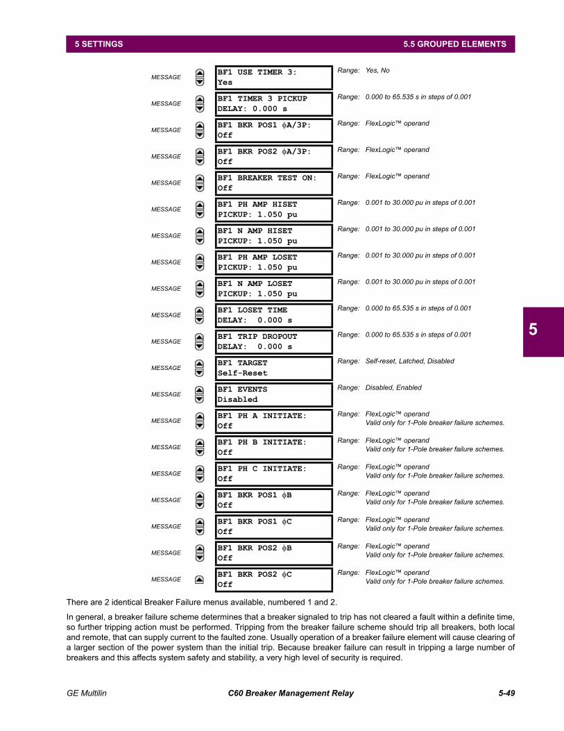
GE Multilin C60 Breaker Management Relay 5-49
5 SETTINGS 5.5 GROUPED ELEMENTS
5
There are 2 identical Breaker Failure menus available, numbered 1 and 2.
In general, a breaker failure scheme determines that a breaker signaled to trip has not cleared a fault within a definite time,so further tripping action must be performed. Tripping from the breaker failure scheme should trip all breakers, both localand remote, that can supply current to the faulted zone. Usually operation of a breaker failure element will cause clearing ofa larger section of the power system than the initial trip. Because breaker failure can result in tripping a large number ofbreakers and this affects system safety and stability, a very high level of security is required.
MESSAGEBF1 USE TIMER 3:Yes
Range: Yes, No
MESSAGEBF1 TIMER 3 PICKUPDELAY: 0.000 s
Range: 0.000 to 65.535 s in steps of 0.001
MESSAGEBF1 BKR POS1 φA/3P:Off
Range: FlexLogic operand
MESSAGEBF1 BKR POS2 φA/3P:Off
Range: FlexLogic operand
MESSAGEBF1 BREAKER TEST ON:Off
Range: FlexLogic operand
MESSAGEBF1 PH AMP HISETPICKUP: 1.050 pu
Range: 0.001 to 30.000 pu in steps of 0.001
MESSAGEBF1 N AMP HISETPICKUP: 1.050 pu
Range: 0.001 to 30.000 pu in steps of 0.001
MESSAGEBF1 PH AMP LOSETPICKUP: 1.050 pu
Range: 0.001 to 30.000 pu in steps of 0.001
MESSAGEBF1 N AMP LOSETPICKUP: 1.050 pu
Range: 0.001 to 30.000 pu in steps of 0.001
MESSAGEBF1 LOSET TIMEDELAY: 0.000 s
Range: 0.000 to 65.535 s in steps of 0.001
MESSAGEBF1 TRIP DROPOUTDELAY: 0.000 s
Range: 0.000 to 65.535 s in steps of 0.001
MESSAGEBF1 TARGETSelf-Reset
Range: Self-reset, Latched, Disabled
MESSAGEBF1 EVENTSDisabled
Range: Disabled, Enabled
MESSAGEBF1 PH A INITIATE:Off
Range: FlexLogic operandValid only for 1-Pole breaker failure schemes.
MESSAGEBF1 PH B INITIATE:Off
Range: FlexLogic operandValid only for 1-Pole breaker failure schemes.
MESSAGEBF1 PH C INITIATE:Off
Range: FlexLogic operandValid only for 1-Pole breaker failure schemes.
MESSAGEBF1 BKR POS1 φBOff
Range: FlexLogic operandValid only for 1-Pole breaker failure schemes.
MESSAGEBF1 BKR POS1 φCOff
Range: FlexLogic operandValid only for 1-Pole breaker failure schemes.
MESSAGEBF1 BKR POS2 φBOff
Range: FlexLogic operandValid only for 1-Pole breaker failure schemes.
MESSAGEBF1 BKR POS2 φCOff
Range: FlexLogic operandValid only for 1-Pole breaker failure schemes.
5-50 C60 Breaker Management Relay GE Multilin
5.5 GROUPED ELEMENTS 5 SETTINGS
5
Two schemes are provided: one for three-pole tripping only (identified by the name "3BF") and one for three pole plus sin-gle-pole operation (identified by the name "1BF"). The philosophy used in these schemes is identical. The operation of abreaker failure element includes three stages: initiation, determination of a breaker failure condition, and output.
INITIATION STAGE:
A FlexLogic operand representing the protection trip signal initially sent to the breaker must be selected to initiate thescheme. The initiating signal should be sealed-in if primary fault detection can reset before the breaker failure timers havefinished timing. The seal-in is supervised by current level, so it is reset when the fault is cleared. If desired, an incompletesequence seal-in reset can be implemented by using the initiating operand to also initiate a FlexLogic timer, set longerthan any breaker failure timer, whose output operand is selected to block the breaker failure scheme.
Schemes can be initiated either directly or with current level supervision. It is particularly important in any application todecide if a current-supervised initiate is to be used. The use of a current-supervised initiate results in the breaker failure ele-ment not being initiated for a breaker that has very little or no current flowing through it, which may be the case for trans-former faults. For those situations where it is required to maintain breaker fail coverage for fault levels below the BF1 PHAMP SUPV PICKUP or the BF1 N AMP SUPV PICKUP setting, a current supervised initiate should not be used. This featureshould be utilized for those situations where coordinating margins may be reduced when high speed reclosing is used.Thus, if this choice is made, fault levels must always be above the supervision pickup levels for dependable operation ofthe breaker fail scheme. This can also occur in breaker-and-a-half or ring bus configurations where the first breaker closesinto a fault; the protection trips and attempts to initiate breaker failure for the second breaker, which is in the process ofclosing, but does not yet have current flowing through it.
When the scheme is initiated, it immediately sends a trip signal to the breaker initially signaled to trip (this feature is usuallydescribed as Re-Trip). This reduces the possibility of widespread tripping that results from a declaration of a failed breaker.
DETERMINATION OF A BREAKER FAILURE CONDITION:
The schemes determine a breaker failure condition via three paths. Each of these paths is equipped with a time delay,after which a failed breaker is declared and trip signals are sent to all breakers required to clear the zone. The delayedpaths are associated with Breaker Failure Timers 1, 2 and 3, which are intended to have delays increasing with increasingtimer numbers. These delayed paths are individually enabled to allow for maximum flexibility.
Timer 1 logic (Early Path) is supervised by a fast-operating breaker auxiliary contact. If the breaker is still closed (as indi-cated by the auxiliary contact) and fault current is detected after the delay interval, an output is issued. Operation of thebreaker auxiliary switch indicates that the breaker has mechanically operated. The continued presence of current indicatesthat the breaker has failed to interrupt the circuit.
Timer 2 logic (Main Path) is not supervised by a breaker auxiliary contact. If fault current is detected after the delay interval,an output is issued. This path is intended to detect a breaker that opens mechanically but fails to interrupt fault current; thelogic therefore does not use a breaker auxiliary contact.
The Timer 1 and 2 paths provide two levels of current supervision, Hiset and Loset, so that the supervision level can bechanged from a current which flows before a breaker inserts an opening resistor into the faulted circuit to a lower level afterresistor insertion. The Hiset detector is enabled after timeout of Timer 1 or 2, along with a timer that will enable the Losetdetector after its delay interval. The delay interval between Hiset and Loset is the expected breaker opening time. Both cur-rent detectors provide a fast operating time for currents at small multiples of the pickup value. The O/C detectors arerequired to operate after the breaker failure delay interval to eliminate the need for very fast resetting O/C detectors.
Timer 3 logic (Slow Path) is supervised by a breaker auxiliary contact and a control switch contact used to indicate that thebreaker is in/out of service, disabling this path when the breaker is out of service for maintenance. There is no current levelcheck in this logic as it is intended to detect low magnitude faults and it is therefore the slowest to operate.
9. OUTPUT:
The outputs from the schemes are:
FlexLogic operands that report on the operation of portions of the scheme
FlexLogic operand used to re-trip the protected breaker
FlexLogic operands that initiate tripping required to clear the faulted zone. The trip output can be sealed-in for anadjustable period.
Target message indicating a failed breaker has been declared
Illumination of the faceplate TRIP LED (and the PHASE A, B or C LED, if applicable)

GE Multilin C60 Breaker Management Relay 5-51
5 SETTINGS 5.5 GROUPED ELEMENTS
5
MAIN PATH SEQUENCE:
Figure 517: BREAKER FAILURE MAIN PATH SEQUENCE
BF1 MODE:
This setting is used to select the breaker failure operating mode: single or three pole.
BF1 USE AMP SUPV:
If set to Yes, the element will only be initiated if current flowing through the breaker is above the supervision pickup level.
BF1 USE SEAL-IN:
If set to Yes, the element will only be sealed-in if current flowing through the breaker is above the supervision pickup level.
BF1 3-POLE INITIATE:
This setting is used to select the FlexLogic operand that will initiate 3-pole tripping of the breaker.
BF1 PH AMP SUPV PICKUP:
This setting is used to set the phase current initiation and seal-in supervision level. Generally this setting should detect thelowest expected fault current on the protected breaker. It can be set as low as necessary (lower than breaker resistor cur-rent or lower than load current) - Hiset and Loset current supervision will guarantee correct operation.
BF1 N AMP SUPV PICKUP (valid only for 3-pole breaker failure schemes):
This setting is used to set the neutral current initiate and seal-in supervision level. Generally this setting should detect thelowest expected fault current on the protected breaker. Neutral current supervision is used only in the three phase schemeto provide increased sensitivity.
BF1 USE TIMER 1:
If set to Yes, the Early Path is operational.
BF1 TIMER 1 PICKUP DELAY:
Timer 1 is set to the shortest time required for breaker auxiliary contact Status-1 to open, from the time the initial trip signalis applied to the breaker trip circuit, plus a safety margin.
BF1 USE TIMER 2:
If set to Yes, the Main Path is operational.
BF1 TIMER 2 PICKUP DELAY:
Timer 2 is set to the expected opening time of the breaker, plus a safety margin. This safety margin was historicallyintended to allow for measuring and timing errors in the breaker failure scheme equipment. In microprocessor relays thistime is not significant. In UR relays, which use a Fourier transform, the calculated current magnitude will ramp-down to zeroone power frequency cycle after the current is interrupted, and this lag should be included in the overall margin duration, asit occurs after current interruption. The BREAKER FAILURE MAIN PATH SEQUENCE diagram shows a margin of twocycles; this interval is considered the minimum appropriate for most applications.
Note that in bulk oil circuit breakers, the interrupting time for currents less than 25% of the interrupting rating can be signifi-cantly longer than the normal interrupting time.
PROTECTION OPERATION BREAKER INTERRUPTING TIME
CALCULATED CURRENT MAGNITUDE
ACTUAL CURRENT MAGNITUDEFAILED INTERRUPTION
CORRECT INTERRUPTION
Rampdown
(ASSUMED 1.5 cycles)
INITIATE (1/8 cycle)BREAKER FAILURE TIMER No. 2 (±1/8 cycle)
BREAKER FAILURE CURRENT DETECTOR PICKUP (1/8 cycle)
BREAKER FAILURE OUTPUT RELAY PICKUP (1/4 cycle)
FAULT
OCCURS
1 2 3 4 5 6 7 8 9 10 110
0
0
AMP
(ASSUMED 3 cycles)
cycles
827083A6.CDR
MARGIN
(Assumed 2 Cycles)
BACKUP BREAKER OPERATING TIME
(Assumed 3 Cycles)

5-52 C60 Breaker Management Relay GE Multilin
5.5 GROUPED ELEMENTS 5 SETTINGS
5
BF1 USE TIMER 3:
If set to Yes, the Slow Path is operational.
BF1 TIMER 3 PICKUP DELAY:
Timer 3 is set to the same interval as Timer 2, plus an increased safety margin. Because this path is intended to operateonly for low level faults, the delay can be in the order of 300 to 500 ms.
BF1 BKR POS1 φA/3P:
This setting selects the FlexLogic operand that represents the protected breaker early-type auxiliary switch contact (52/a). When using 1-Pole breaker failure scheme, this operand represents the protected breaker early-type auxiliary switchcontact on pole A. This is normally a non-multiplied Form-A contact. The contact may even be adjusted to have the shortestpossible operating time.
BF1 BKR POS2 φA/3P:
This setting selects the FlexLogic operand that represents the breaker normal-type auxiliary switch contact (52/a). Whenusing 1-Pole breaker failure scheme, this operand represents the protected breaker auxiliary switch contact on pole A. Thismay be a multiplied contact.
BF1 BREAKER TEST ON:
This setting is used to select the FlexLogic operand that represents the breaker In-Service/Out-of-Service switch set tothe Out-of-Service position.
BF1 PH AMP HISET PICKUP:
This setting is used to set the phase current output supervision level. Generally this setting should detect the lowestexpected fault current on the protected breaker, before a breaker opening resistor is inserted.
BF1 N AMP HISET PICKUP (valid only for 3-pole breaker failure schemes):
This setting sets the neutral current output supervision level. Generally this setting should detect the lowest expected faultcurrent on the protected breaker, before a breaker opening resistor is inserted. Neutral current supervision is used only inthe three pole scheme to provide increased sensitivity.
BF1 PH AMP LOSET PICKUP:
This setting sets the phase current output supervision level. Generally this setting should detect the lowest expected faultcurrent on the protected breaker, after a breaker opening resistor is inserted (approximately 90% of the resistor current).
BF1 N AMP LOSET PICKUP (valid only for 3-pole breaker failure schemes):
This setting sets the neutral current output supervision level. Generally this setting should detect the lowest expected faultcurrent on the protected breaker, after a breaker opening resistor is inserted (approximately 90% of the resistor current).
BF1 LOSET TIME DELAY:
This setting is used to set the pickup delay for current detection after opening resistor insertion.
BF1 TRIP DROPOUT DELAY:
This setting is used to set the period of time for which the trip output is sealed-in. This timer must be coordinated with theautomatic reclosing scheme of the failed breaker, to which the breaker failure element sends a cancel reclosure signal.Reclosure of a remote breaker can also be prevented by holding a Transfer Trip signal on longer than the "reclaim" time.
BF1 PH A INITIATE / BF1 PH B INITIATE / BF 1 PH C INITIATE: (only valid for 1-pole breaker failure schemes)
These settings select the FlexLogic operand to initiate phase A, B, or C single-pole tripping of the breaker and the phaseA, B, or C portion of the scheme, accordingly.
BF1 BKR POS1 φB / BF1 BKR POS 1 φC (valid only for 1-pole breaker failure schemes):
These settings select the FlexLogic operand to represents the protected breaker early-type auxiliary switch contact onpoles B or C, accordingly. This contact is normally a non-multiplied Form-A contact. The contact may even be adjusted tohave the shortest possible operating time.
BF1 BKR POS2 φB (valid only for 1-pole breaker failure schemes):
Selects the FlexLogic operand that represents the protected breaker normal-type auxiliary switch contact on pole B (52/a). This may be a multiplied contact.
GE Multilin C60 Breaker Management Relay 5-53
5 SETTINGS 5.5 GROUPED ELEMENTS
5
BF1 BKR POS2 φC (valid only for 1-pole breaker failure schemes):
This setting selects the FlexLogic operand that represents the protected breaker normal-type auxiliary switch contact onpole C (52/a). This may be a multiplied contact. For single-pole operation, the scheme has the same overall general con-cept except that it provides re-tripping of each single pole of the protected breaker. The approach shown in the followingsingle pole tripping diagram uses the initiating information to determine which pole is supposed to trip. The logic is segre-gated on a per-pole basis. The overcurrent detectors have ganged settings.
Upon operation of the breaker failure element for a single pole trip command, a 3-pole trip command should be given viaoutput operand BKR FAIL 1 TRIP OP.
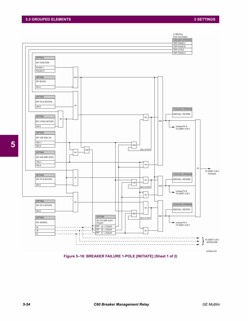
5-54 C60 Breaker Management Relay GE Multilin
5.5 GROUPED ELEMENTS 5 SETTINGS
5
Figure 518: BREAKER FAILURE 1-POLE [INITIATE] (Sheet 1 of 2)
SETTING
SETTING
SETTING
SETTING
SETTING
SETTING
SETTING
SETTING
SETTING
FLEXLOGIC OPERAND
FLEXLOGIC OPERANDS
FLEXLOGIC OPERAND
FLEXLOGIC OPERAND
SETTING
BF1 FUNCTION:
BF1 PH A INITIATE:
BF1 USE SEAL-IN:
BF1 USE AMP SUPV:
BF1 BLOCK :
BF1 3-POLE INITIATE :
BF1 PH B INITIATE :
BF1 PH C INITIATE :
BKR FAIL 1 RETRIPA
TRIP PHASE C
In D60 OnlyFrom Trip Output
TRIP PHASE B
TRIP 3-POLE
TRIP PHASE A
BKR FAIL 1 RETRIPB
BKR FAIL 1 RETRIPC
BF1 SOURCE :BF1 PH AMP SUPVPICKUP :
IA IA PICKUPRUN
IB IB PICKUPRUN
IC IC PICKUPRUN
Off=0
Off=0
Off=0
Off=0
Enable=1
Off=0
YES=1
YES=1
Disable=0
NO=0
NO=0
AND
OR
OR
OR
OR
OR
AND
OR
OR
OR
OR
OR
OR
ANDAND
AND
AND
OR
AND
AND
TO SHEET 2 OF 2(Initiated)
Initiated Ph ATO SHEET 2 OF 2
Initiated Ph BTO SHEET 2 OF 2
SEAL-IN PATH
SEAL-IN PATH
SEAL-IN PATH
Initiated Ph CTO SHEET 2 OF 2
TO SHEET 2 OF 2(827070.CDR)827069A5.CDR
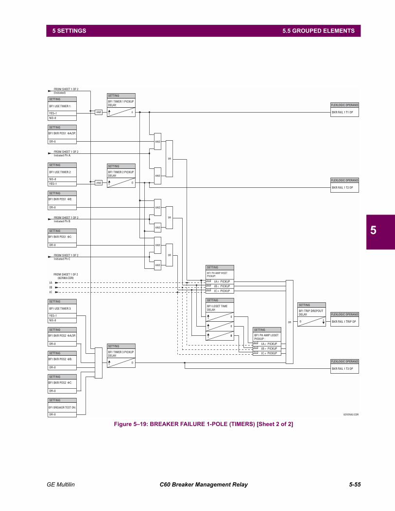
GE Multilin C60 Breaker Management Relay 5-55
5 SETTINGS 5.5 GROUPED ELEMENTS
5
Figure 519: BREAKER FAILURE 1-POLE (TIMERS) [Sheet 2 of 2]
SETTING
SETTING
SETTING
FROM SHEET 1 OF 2(Initiated)
FROM SHEET 1 OF 2Initiated Ph A
FROM SHEET 1 OF 2Initiated Ph B
FROM SHEET 1 OF 2Initiated Ph C
SETTING
SETTING
SETTING
SETTING
SETTING
SETTING
SETTING
SETTING
SETTING
FLEXLOGIC OPERAND
FLEXLOGIC OPERAND
FLEXLOGIC OPERAND
FLEXLOGIC OPERAND
SETTING
SETTING
SETTING
SETTING
SETTING
BF1 USE TIMER 1:
BF1 USE TIMER 2:
BF1 USE TIMER 3:
BF1 BKR POS1 A/3P:
BF1 BKR POS2 A/3P:
BF1 BKR POS1 B:
BF1 BKR POS2 B:
BF1 BKR POS1 C:
BF1 BKR POS2 C:
BF1 TIMER 3 PICKUPDELAY:
BF1 TRIP DROPOUTDELAY:
BKR FAIL 1 TRIP OP
BKR FAIL 1 T3 OP
827070A3.CDR
BKR FAIL 1 T2 OP
BKR FAIL 1 T1 OP
BF1 TIMER 2 PICKUPDELAY:
BF1 TIMER 1 PICKUPDELAY:
BF1 BREAKER TEST ON:
FROM SHEET 1 OF 2(827069.CDR)
BF1 PH AMP HISETPICKUP:
BF1 LOSET TIMEDELAY:
BF1 PH AMP LOSETPICKUP :
IA IA PICKUP
IA PICKUP
RUN
RUN
IB IB PICKUP
IB PICKUP
RUN
RUN
IC IC PICKUP
IC PICKUP
RUN
RUN
Off=0
Off=0
Off=0
Off=0
Off=0
Off=0
Off=0
YES=1
NO=0
YES=1
NO=0
YES=1
NO=0
AND 0
0
0
0
0
00
AND
AND
AND
AND
AND
AND
AND
OR
OR
OR
OR
0
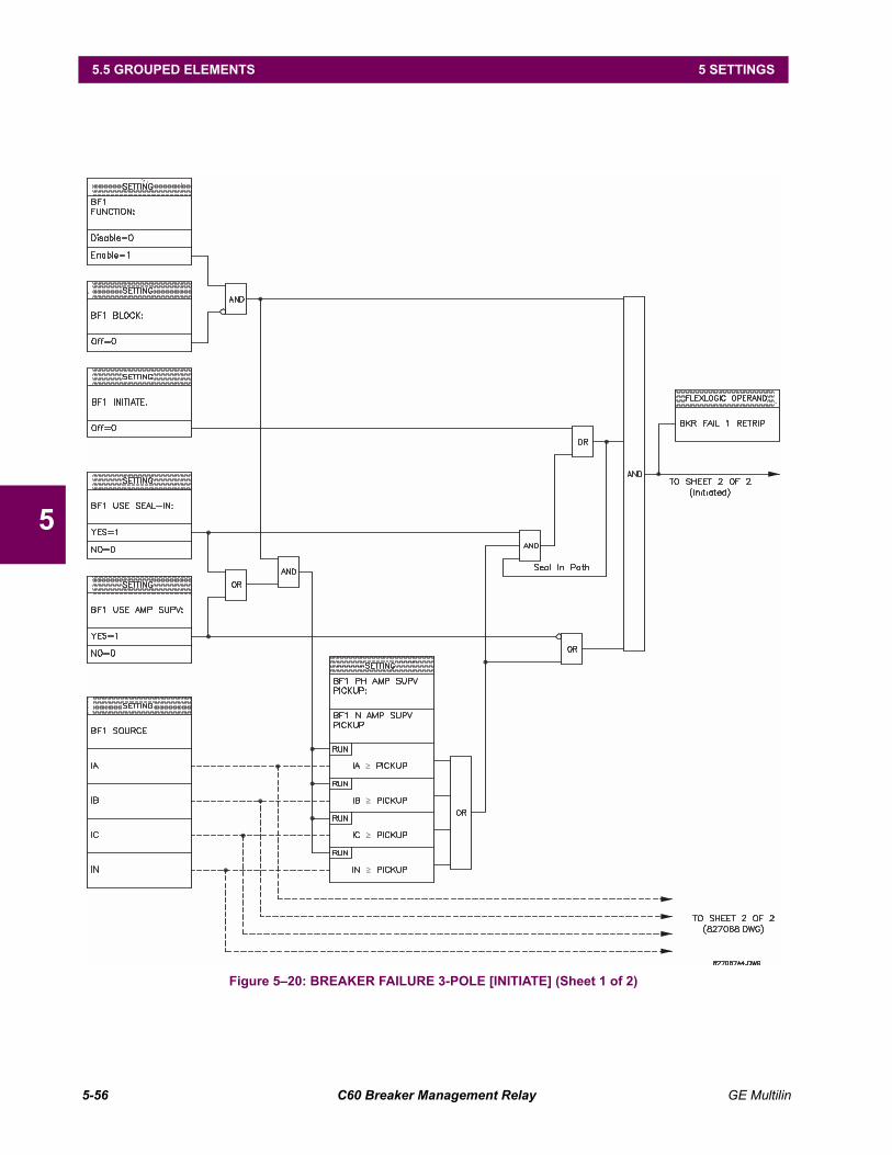
5-56 C60 Breaker Management Relay GE Multilin
5.5 GROUPED ELEMENTS 5 SETTINGS
5
Figure 520: BREAKER FAILURE 3-POLE [INITIATE] (Sheet 1 of 2)
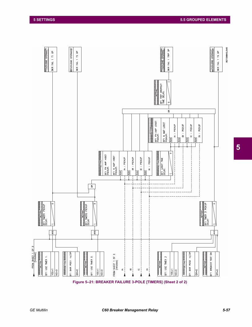
GE Multilin C60 Breaker Management Relay 5-57
5 SETTINGS 5.5 GROUPED ELEMENTS
5
Figure 521: BREAKER FAILURE 3-POLE [TIMERS] (Sheet 2 of 2)
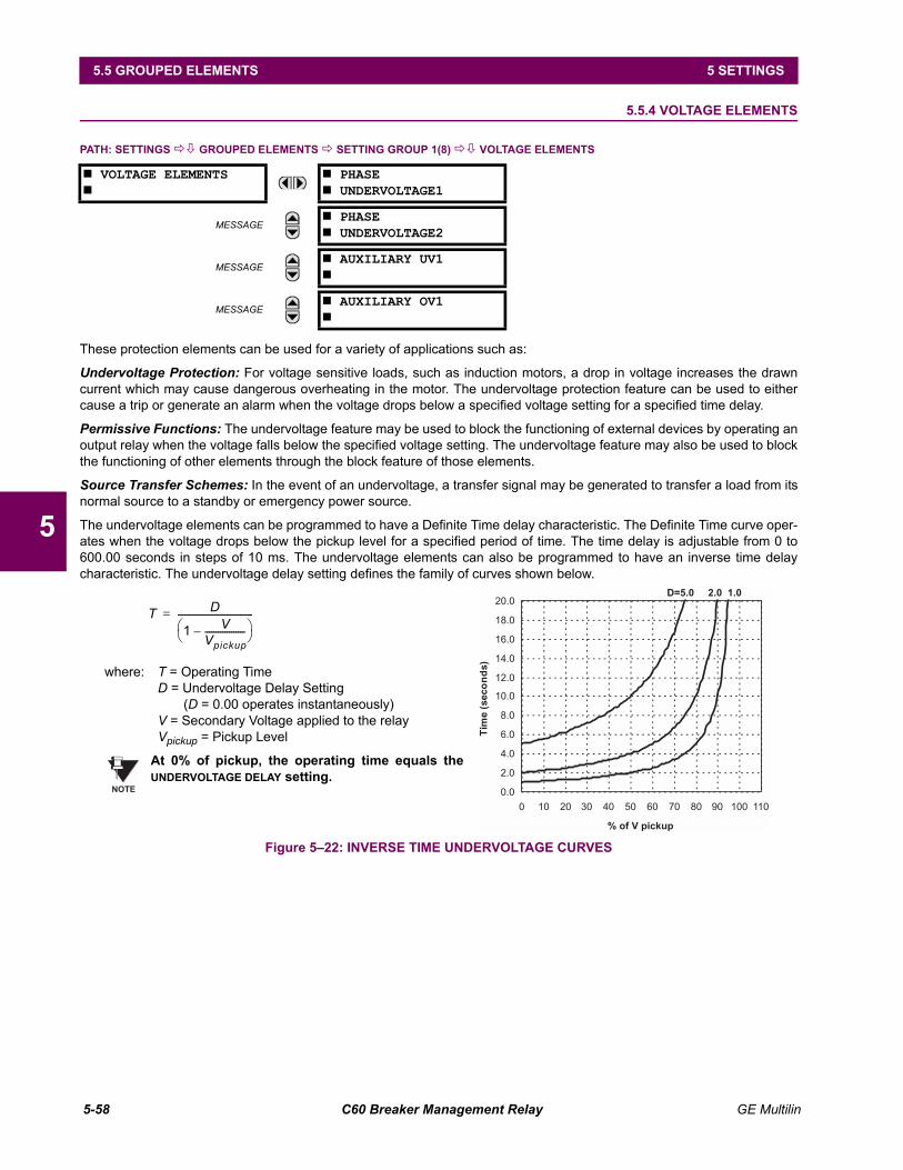
5-58 C60 Breaker Management Relay GE Multilin
5.5 GROUPED ELEMENTS 5 SETTINGS
5
5.5.4 VOLTAGE ELEMENTS
PATH: SETTINGS !" GROUPED ELEMENTS ! SETTING GROUP 1(8) !" VOLTAGE ELEMENTS
These protection elements can be used for a variety of applications such as:
Undervoltage Protection: For voltage sensitive loads, such as induction motors, a drop in voltage increases the drawncurrent which may cause dangerous overheating in the motor. The undervoltage protection feature can be used to eithercause a trip or generate an alarm when the voltage drops below a specified voltage setting for a specified time delay.
Permissive Functions: The undervoltage feature may be used to block the functioning of external devices by operating anoutput relay when the voltage falls below the specified voltage setting. The undervoltage feature may also be used to blockthe functioning of other elements through the block feature of those elements.
Source Transfer Schemes: In the event of an undervoltage, a transfer signal may be generated to transfer a load from itsnormal source to a standby or emergency power source.
The undervoltage elements can be programmed to have a Definite Time delay characteristic. The Definite Time curve oper-ates when the voltage drops below the pickup level for a specified period of time. The time delay is adjustable from 0 to600.00 seconds in steps of 10 ms. The undervoltage elements can also be programmed to have an inverse time delaycharacteristic. The undervoltage delay setting defines the family of curves shown below.
Figure 522: INVERSE TIME UNDERVOLTAGE CURVES
# VOLTAGE ELEMENTS#
# PHASE# UNDERVOLTAGE1
MESSAGE# PHASE# UNDERVOLTAGE2
MESSAGE# AUXILIARY UV1#
MESSAGE# AUXILIARY OV1#
D=5.0 2.0 1.0
0.0
2.0
4.0
6.0
8.0
10.0
12.0
14.0
16.0
18.0
20.0
0 10 20 30 40 50 60 70 80 90 100 110
% of V pickup
Tim
e(s
eco
nd
s)
where: T = Operating TimeD = Undervoltage Delay Setting
(D = 0.00 operates instantaneously)V = Secondary Voltage applied to the relayVpickup = Pickup Level
At 0% of pickup, the operating time equals theUNDERVOLTAGE DELAY setting.
T D
1 VVpickup------------------–
----------------------------------=
NOTE
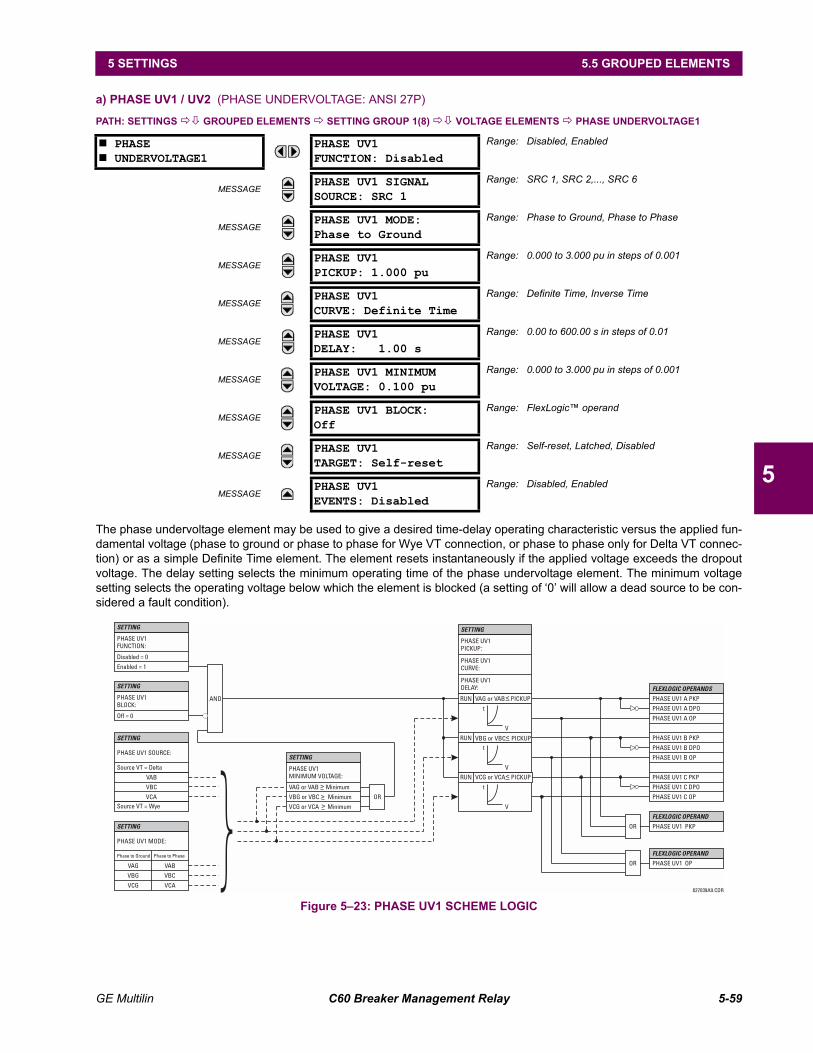
GE Multilin C60 Breaker Management Relay 5-59
5 SETTINGS 5.5 GROUPED ELEMENTS
5
a) PHASE UV1 / UV2 (PHASE UNDERVOLTAGE: ANSI 27P)
PATH: SETTINGS !" GROUPED ELEMENTS ! SETTING GROUP 1(8) !" VOLTAGE ELEMENTS ! PHASE UNDERVOLTAGE1
The phase undervoltage element may be used to give a desired time-delay operating characteristic versus the applied fun-damental voltage (phase to ground or phase to phase for Wye VT connection, or phase to phase only for Delta VT connec-tion) or as a simple Definite Time element. The element resets instantaneously if the applied voltage exceeds the dropoutvoltage. The delay setting selects the minimum operating time of the phase undervoltage element. The minimum voltagesetting selects the operating voltage below which the element is blocked (a setting of 0 will allow a dead source to be con-sidered a fault condition).
Figure 523: PHASE UV1 SCHEME LOGIC
# PHASE# UNDERVOLTAGE1
PHASE UV1FUNCTION: Disabled
Range: Disabled, Enabled
MESSAGEPHASE UV1 SIGNALSOURCE: SRC 1
Range: SRC 1, SRC 2,..., SRC 6
MESSAGEPHASE UV1 MODE:Phase to Ground
Range: Phase to Ground, Phase to Phase
MESSAGEPHASE UV1PICKUP: 1.000 pu
Range: 0.000 to 3.000 pu in steps of 0.001
MESSAGEPHASE UV1CURVE: Definite Time
Range: Definite Time, Inverse Time
MESSAGEPHASE UV1DELAY: 1.00 s
Range: 0.00 to 600.00 s in steps of 0.01
MESSAGEPHASE UV1 MINIMUMVOLTAGE: 0.100 pu
Range: 0.000 to 3.000 pu in steps of 0.001
MESSAGEPHASE UV1 BLOCK:Off
Range: FlexLogic operand
MESSAGEPHASE UV1TARGET: Self-reset
Range: Self-reset, Latched, Disabled
MESSAGEPHASE UV1EVENTS: Disabled
Range: Disabled, Enabled
PHASE UV1FUNCTION:
PHASE UV1BLOCK:
PHASE UV1 SOURCE:
PHASE UV1 MODE:
PHASE UV1PICKUP:
PHASE UV1CURVE:
PHASE UV1DELAY:
PHASE UV1MINIMUM VOLTAGE:
Disabled = 0
Off = 0
Source VT = Delta
Phase to Ground Phase to Phase
RUN
RUN
VCG or VCA PICKUP
VBG or VBC PICKUP
VAG or VAB Minimum
VBG or VBC Minimum
VCG or VCA MinimumSource VT = Wye
VAG VAB
VBG VBC
VCG VCA
Enabled = 1
VAB
VBC
VCA
PHASE UV1 A PKP
PHASE UV1 B PKP
PHASE UV1 C PKP
PHASE UV1 PKP
PHASE UV1 A DPO
PHASE UV1 B DPO
PHASE UV1 C DPO
PHASE UV1 A OP
PHASE UV1 B OP
PHASE UV1 C OP
PHASE UV1 OP
AND
SETTING
SETTING
SETTING
SETTING
SETTING
SETTING
FLEXLOGIC OPERANDS
FLEXLOGIC OPERAND
FLEXLOGIC OPERAND
827039A9.CDR
OR
OR
OR
<
<
<
<
<
t
V
t
t
V
V
VAG or VAB PICKUP<RUN
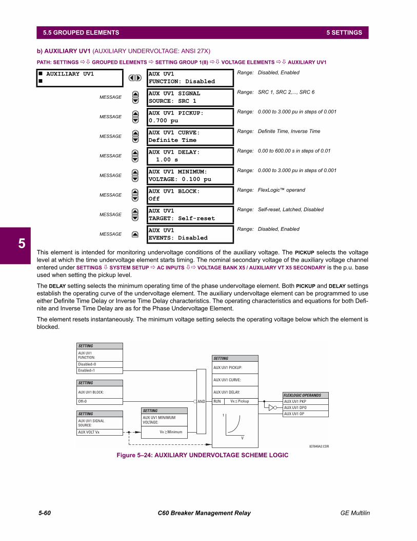
5-60 C60 Breaker Management Relay GE Multilin
5.5 GROUPED ELEMENTS 5 SETTINGS
5
b) AUXILIARY UV1 (AUXILIARY UNDERVOLTAGE: ANSI 27X)
PATH: SETTINGS !" GROUPED ELEMENTS ! SETTING GROUP 1(8) !" VOLTAGE ELEMENTS !" AUXILIARY UV1
This element is intended for monitoring undervoltage conditions of the auxiliary voltage. The PICKUP selects the voltagelevel at which the time undervoltage element starts timing. The nominal secondary voltage of the auxiliary voltage channelentered under SETTINGS " SYSTEM SETUP ! AC INPUTS "! VOLTAGE BANK X5 / AUXILIARY VT X5 SECONDARY is the p.u. baseused when setting the pickup level.
The DELAY setting selects the minimum operating time of the phase undervoltage element. Both PICKUP and DELAY settingsestablish the operating curve of the undervoltage element. The auxiliary undervoltage element can be programmed to useeither Definite Time Delay or Inverse Time Delay characteristics. The operating characteristics and equations for both Defi-nite and Inverse Time Delay are as for the Phase Undervoltage Element.
The element resets instantaneously. The minimum voltage setting selects the operating voltage below which the element isblocked.
Figure 524: AUXILIARY UNDERVOLTAGE SCHEME LOGIC
# AUXILIARY UV1#
AUX UV1FUNCTION: Disabled
Range: Disabled, Enabled
MESSAGEAUX UV1 SIGNALSOURCE: SRC 1
Range: SRC 1, SRC 2,..., SRC 6
MESSAGEAUX UV1 PICKUP:0.700 pu
Range: 0.000 to 3.000 pu in steps of 0.001
MESSAGEAUX UV1 CURVE:Definite Time
Range: Definite Time, Inverse Time
MESSAGEAUX UV1 DELAY:
1.00 sRange: 0.00 to 600.00 s in steps of 0.01
MESSAGEAUX UV1 MINIMUM:VOLTAGE: 0.100 pu
Range: 0.000 to 3.000 pu in steps of 0.001
MESSAGEAUX UV1 BLOCK:Off
Range: FlexLogic operand
MESSAGEAUX UV1TARGET: Self-reset
Range: Self-reset, Latched, Disabled
MESSAGEAUX UV1EVENTS: Disabled
Range: Disabled, Enabled
827849A2.CDR
FLEXLOGIC OPERANDS
AUX UV1FUNCTION:
AUX UV1 BLOCK:
AUX UV1 SIGNALSOURCE:
AUX UV1 MINIMUMVOLTAGE:
AUX UV1 DPO
AUX UV1 OP
AUX UV1 PKPRUN
SETTING
SETTING
AUX UV1 CURVE:
AUX UV1 DELAY:
AUX UV1 PICKUP:
SETTING
Enabled=1
Disabled=0
SETTING
SETTING
Off=0
AUX VOLT Vx Vx Minimum
Vx Pickup
t
V
<
<AND
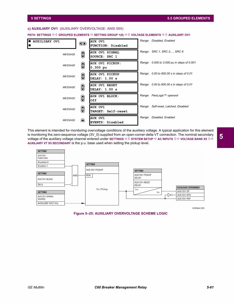
GE Multilin C60 Breaker Management Relay 5-61
5 SETTINGS 5.5 GROUPED ELEMENTS
5
c) AUXILIARY OV1 (AUXILIARY OVERVOLTAGE: ANSI 59X)
PATH: SETTINGS !" GROUPED ELEMENTS ! SETTING GROUP 1(8) !" VOLTAGE ELEMENTS !" AUXILIARY OV1
This element is intended for monitoring overvoltage conditions of the auxiliary voltage. A typical application for this elementis monitoring the zero-sequence voltage (3V_0) supplied from an open-corner-delta VT connection. The nominal secondaryvoltage of the auxiliary voltage channel entered under SETTINGS !" SYSTEM SETUP ! AC INPUTS "! VOLTAGE BANK X5 "!AUXILIARY VT X5 SECONDARY is the p.u. base used when setting the pickup level.
Figure 525: AUXILIARY OVERVOLTAGE SCHEME LOGIC
# AUXILIARY OV1#
AUX OV1FUNCTION: Disabled
Range: Disabled, Enabled
MESSAGEAUX OV1 SIGNALSOURCE: SRC 1
Range: SRC 1, SRC 2,..., SRC 6
MESSAGEAUX OV1 PICKUP:0.300 pu
Range: 0.000 to 3.000 pu in steps of 0.001
MESSAGEAUX OV1 PICKUPDELAY: 1.00 s
Range: 0.00 to 600.00 s in steps of 0.01
MESSAGEAUX OV1 RESETDELAY: 1.00 s
Range: 0.00 to 600.00 s in steps of 0.01
MESSAGEAUX OV1 BLOCK:Off
Range: FlexLogic operand
MESSAGEAUX OV1TARGET: Self-reset
Range: Self-reset, Latched, Disabled
MESSAGEAUX OV1EVENTS: Disabled
Range: Disabled, Enabled
827836A2.CDR
FLEXLOGIC OPERANDS
AUX OV1FUNCTION:
AUX OV1 BLOCK:
AUX OV1 SIGNALSOURCE:
AUX OV1 PICKUP:
AUX OV1 DPO
AUX OV1 OP
AUX OV1 PKP
RUNAND
SETTING
SETTING
AUX OV1 RESETDELAY :
AUX OV1 PICKUPDELAY :
SETTING
Enabled=1
Disabled=0
tPKP
tRST
SETTING
SETTING
Off=0
AUXILIARY VOLT (Vx)
Vx Pickup<
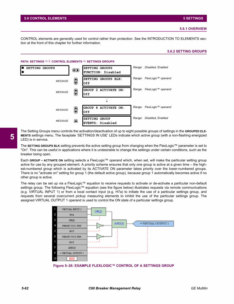
5-62 C60 Breaker Management Relay GE Multilin
5.6 CONTROL ELEMENTS 5 SETTINGS
5
5.6 CONTROL ELEMENTS 5.6.1 OVERVIEW
CONTROL elements are generally used for control rather than protection. See the INTRODUCTION TO ELEMENTS sec-tion at the front of this chapter for further information.
5.6.2 SETTING GROUPS
PATH: SETTINGS !" CONTROL ELEMENTS ! SETTINGS GROUPS
The Setting Groups menu controls the activation/deactivation of up to eight possible groups of settings in the GROUPED ELE-MENTS settings menu. The faceplate SETTINGS IN USE LEDs indicate which active group (with a non-flashing energizedLED) is in service.
The SETTING GROUPS BLK setting prevents the active setting group from changing when the FlexLogic parameter is set to"On". This can be useful in applications where it is undesirable to change the settings under certain conditions, such as thebreaker being open.
Each GROUP ~ ACTIVATE ON setting selects a FlexLogic operand which, when set, will make the particular setting groupactive for use by any grouped element. A priority scheme ensures that only one group is active at a given time the high-est-numbered group which is activated by its ACTIVATE ON parameter takes priority over the lower-numbered groups.There is no "activate on" setting for group 1 (the default active group), because group 1 automatically becomes active if noother group is active.
The relay can be set up via a FlexLogic equation to receive requests to activate or de-activate a particular non-defaultsettings group. The following FlexLogic equation (see the figure below) illustrates requests via remote communications(e.g. VIRTUAL INPUT 1) or from a local contact input (e.g. H7a) to initiate the use of a particular settings group, andrequests from several overcurrent pickup measuring elements to inhibit the use of the particular settings group. Theassigned VIRTUAL OUTPUT 1 operand is used to control the ON state of a particular settings group.
Figure 526: EXAMPLE FLEXLOGIC CONTROL OF A SETTINGS GROUP
# SETTING GROUPS#
SETTING GROUPSFUNCTION: Disabled
Range: Disabled, Enabled
MESSAGESETTING GROUPS BLK:Off
Range: FlexLogic operand
MESSAGEGROUP 2 ACTIVATE ON:Off
Range: FlexLogic operand
↓
MESSAGEGROUP 8 ACTIVATE ON:Off
Range: FlexLogic operand
MESSAGESETTING GROUPEVENTS: Disabled
Range: Disabled, Enabled
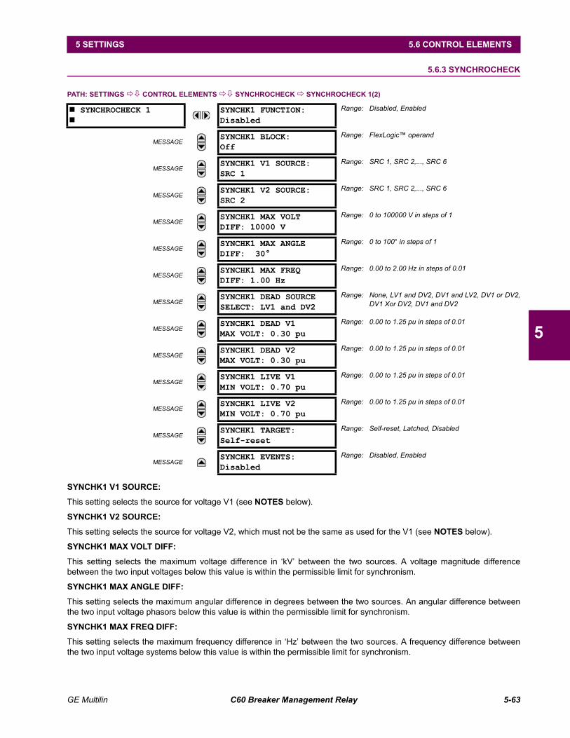
GE Multilin C60 Breaker Management Relay 5-63
5 SETTINGS 5.6 CONTROL ELEMENTS
5
5.6.3 SYNCHROCHECK
PATH: SETTINGS !" CONTROL ELEMENTS !" SYNCHROCHECK ! SYNCHROCHECK 1(2)
SYNCHK1 V1 SOURCE:
This setting selects the source for voltage V1 (see NOTES below).
SYNCHK1 V2 SOURCE:
This setting selects the source for voltage V2, which must not be the same as used for the V1 (see NOTES below).
SYNCHK1 MAX VOLT DIFF:
This setting selects the maximum voltage difference in kV between the two sources. A voltage magnitude differencebetween the two input voltages below this value is within the permissible limit for synchronism.
SYNCHK1 MAX ANGLE DIFF:
This setting selects the maximum angular difference in degrees between the two sources. An angular difference betweenthe two input voltage phasors below this value is within the permissible limit for synchronism.
SYNCHK1 MAX FREQ DIFF:
This setting selects the maximum frequency difference in Hz between the two sources. A frequency difference betweenthe two input voltage systems below this value is within the permissible limit for synchronism.
# SYNCHROCHECK 1#
SYNCHK1 FUNCTION:Disabled
Range: Disabled, Enabled
MESSAGESYNCHK1 BLOCK:Off
Range: FlexLogic operand
MESSAGESYNCHK1 V1 SOURCE:SRC 1
Range: SRC 1, SRC 2,..., SRC 6
MESSAGESYNCHK1 V2 SOURCE:SRC 2
Range: SRC 1, SRC 2,..., SRC 6
MESSAGESYNCHK1 MAX VOLTDIFF: 10000 V
Range: 0 to 100000 V in steps of 1
MESSAGESYNCHK1 MAX ANGLEDIFF: 30°
Range: 0 to 100° in steps of 1
MESSAGESYNCHK1 MAX FREQDIFF: 1.00 Hz
Range: 0.00 to 2.00 Hz in steps of 0.01
MESSAGESYNCHK1 DEAD SOURCESELECT: LV1 and DV2
Range: None, LV1 and DV2, DV1 and LV2, DV1 or DV2,DV1 Xor DV2, DV1 and DV2
MESSAGESYNCHK1 DEAD V1MAX VOLT: 0.30 pu
Range: 0.00 to 1.25 pu in steps of 0.01
MESSAGESYNCHK1 DEAD V2MAX VOLT: 0.30 pu
Range: 0.00 to 1.25 pu in steps of 0.01
MESSAGESYNCHK1 LIVE V1MIN VOLT: 0.70 pu
Range: 0.00 to 1.25 pu in steps of 0.01
MESSAGESYNCHK1 LIVE V2MIN VOLT: 0.70 pu
Range: 0.00 to 1.25 pu in steps of 0.01
MESSAGESYNCHK1 TARGET:Self-reset
Range: Self-reset, Latched, Disabled
MESSAGESYNCHK1 EVENTS:Disabled
Range: Disabled, Enabled
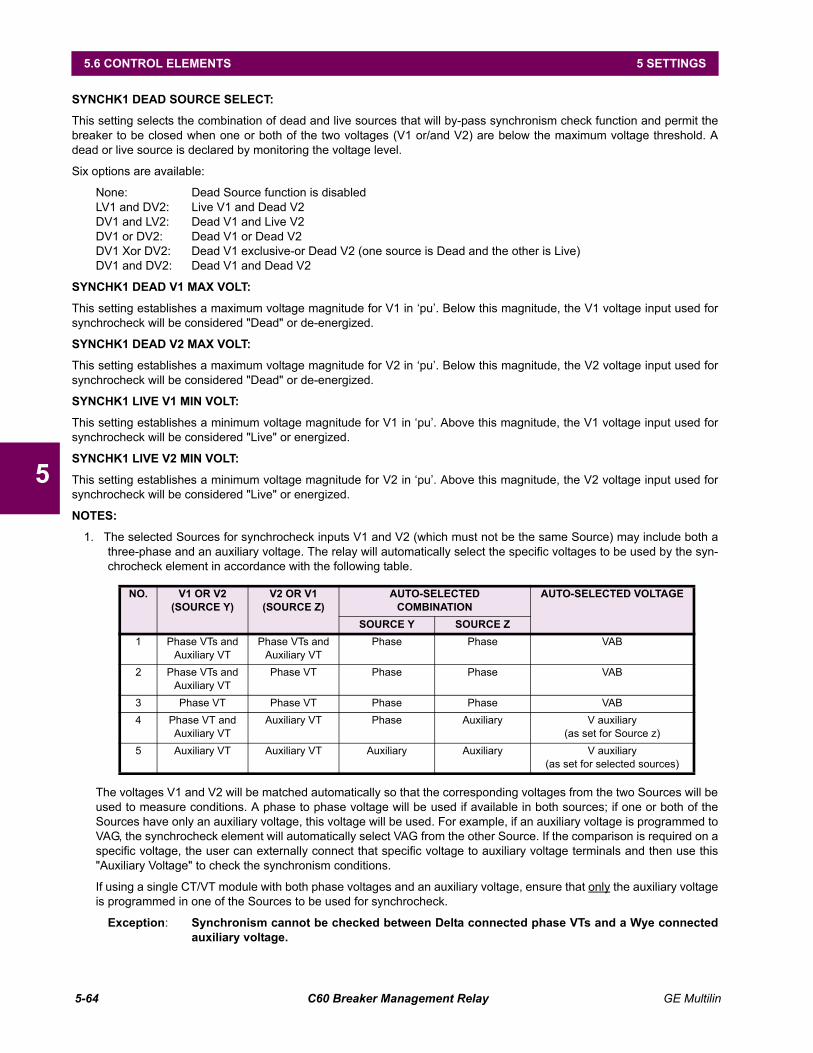
5-64 C60 Breaker Management Relay GE Multilin
5.6 CONTROL ELEMENTS 5 SETTINGS
5
SYNCHK1 DEAD SOURCE SELECT:
This setting selects the combination of dead and live sources that will by-pass synchronism check function and permit thebreaker to be closed when one or both of the two voltages (V1 or/and V2) are below the maximum voltage threshold. Adead or live source is declared by monitoring the voltage level.
Six options are available:
None: Dead Source function is disabledLV1 and DV2: Live V1 and Dead V2DV1 and LV2: Dead V1 and Live V2DV1 or DV2: Dead V1 or Dead V2DV1 Xor DV2: Dead V1 exclusive-or Dead V2 (one source is Dead and the other is Live)DV1 and DV2: Dead V1 and Dead V2
SYNCHK1 DEAD V1 MAX VOLT:
This setting establishes a maximum voltage magnitude for V1 in pu. Below this magnitude, the V1 voltage input used forsynchrocheck will be considered "Dead" or de-energized.
SYNCHK1 DEAD V2 MAX VOLT:
This setting establishes a maximum voltage magnitude for V2 in pu. Below this magnitude, the V2 voltage input used forsynchrocheck will be considered "Dead" or de-energized.
SYNCHK1 LIVE V1 MIN VOLT:
This setting establishes a minimum voltage magnitude for V1 in pu. Above this magnitude, the V1 voltage input used forsynchrocheck will be considered "Live" or energized.
SYNCHK1 LIVE V2 MIN VOLT:
This setting establishes a minimum voltage magnitude for V2 in pu. Above this magnitude, the V2 voltage input used forsynchrocheck will be considered "Live" or energized.
NOTES:
1. The selected Sources for synchrocheck inputs V1 and V2 (which must not be the same Source) may include both athree-phase and an auxiliary voltage. The relay will automatically select the specific voltages to be used by the syn-chrocheck element in accordance with the following table.
The voltages V1 and V2 will be matched automatically so that the corresponding voltages from the two Sources will beused to measure conditions. A phase to phase voltage will be used if available in both sources; if one or both of theSources have only an auxiliary voltage, this voltage will be used. For example, if an auxiliary voltage is programmed toVAG, the synchrocheck element will automatically select VAG from the other Source. If the comparison is required on aspecific voltage, the user can externally connect that specific voltage to auxiliary voltage terminals and then use this"Auxiliary Voltage" to check the synchronism conditions.
If using a single CT/VT module with both phase voltages and an auxiliary voltage, ensure that only the auxiliary voltageis programmed in one of the Sources to be used for synchrocheck.
Exception: Synchronism cannot be checked between Delta connected phase VTs and a Wye connectedauxiliary voltage.
NO. V1 OR V2(SOURCE Y)
V2 OR V1(SOURCE Z)
AUTO-SELECTEDCOMBINATION
AUTO-SELECTED VOLTAGE
SOURCE Y SOURCE Z1 Phase VTs and
Auxiliary VTPhase VTs and
Auxiliary VTPhase Phase VAB
2 Phase VTs and Auxiliary VT
Phase VT Phase Phase VAB
3 Phase VT Phase VT Phase Phase VAB4 Phase VT and
Auxiliary VTAuxiliary VT Phase Auxiliary V auxiliary
(as set for Source z)5 Auxiliary VT Auxiliary VT Auxiliary Auxiliary V auxiliary
(as set for selected sources)
GE Multilin C60 Breaker Management Relay 5-65
5 SETTINGS 5.6 CONTROL ELEMENTS
5
2. The relay measures frequency and Volts/Hz from an input on a given Source with priorities as established by the con-figuration of input channels to the Source. The relay will use the phase channel of a three-phase set of voltages ifprogrammed as part of that Source. The relay will use the auxiliary voltage channel only if that channel is pro-grammed as part of the Source and a three-phase set is not.
The are two identical synchrocheck elements available, numbered 1 and 2.
The synchronism check function is intended for supervising the paralleling of two parts of a system which are to be joinedby the closure of a circuit breaker. The synchrocheck elements are typically used at locations where the two parts of thesystem are interconnected through at least one other point in the system.
Synchrocheck verifies that the voltages (V1 and V2) on the two sides of the supervised circuit breaker are within set limitsof magnitude, angle and frequency differences.
The time while the two voltages remain within the admissible angle difference is determined by the setting of the phaseangle difference ∆Φ and the frequency difference ∆F (slip frequency). It can be defined as the time it would take the voltagephasor V1 or V2 to traverse an angle equal to 2 × ∆Φ at a frequency equal to the frequency difference ∆F. This time can becalculated by:
where: ∆Φ = phase angle difference in degrees; ∆F = frequency difference in Hz.
As an example; for the default values (∆Φ = 30°, ∆F = 0.1 Hz), the time while the angle between the two voltages will beless than the set value is:
If one or both sources are de-energized, the synchrocheck programming can allow for closing of the circuit breaker usingundervoltage control to by-pass the synchrocheck measurements (Dead Source function).
T 1360°
2 ∆Φ×------------------ ∆F×--------------------------------=
T 1360°
2 ∆Φ×------------------ ∆F×-------------------------------- 1
360°2 30°×------------------- 0.1 Hz×------------------------------------------- 1.66 sec.= = =

5-66 C60 Breaker Management Relay GE Multilin
5.6 CONTROL ELEMENTS 5 SETTINGS
5
Figure 527: SYNCHROCHECK SCHEME LOGIC
SETT
ING
SETT
ING
FLEX
LOG
IC O
PERA
ND
S
FLEX
LOG
IC O
PERA
ND
S
FLEX
LOG
IC O
PERA
ND
S
SETT
ING
SETT
ING
SETT
ING
SETT
ING
SETT
ING
SETT
ING
SETT
ING
SETT
ING
CALC
ULA
TEA
CTU
AL
VALU
E
ACT
UA
L VA
LUE
ACT
UA
L VA
LUE
CALC
ULA
TE
SYN
CHK1
FU
NCT
ION
:
SYN
CHK1
BLO
CK:
Calc
ulat
eI V
1-V2
I=
V
Calc
ulat
eI F
1-F2
I=
F
Calc
ulat
eI
1-
2 I=
SYN
CHK1
MA
X VO
LTD
IFF:
SYN
CHK1
MA
X A
NG
LED
IFF:
SYN
CHK1
MA
X FR
EQD
IFF:
Mag
nitu
de V
2SY
NC1
:
SYN
C1:
V
SYN
C1:
F
Mag
nitu
de V
1
Ang
le
2
Ang
le
1
8270
76A
7.CD
R
SYN
C1 D
EAD
S O
P
SYN
C1 C
LS O
P
SYN
C1 S
YNC
OP
SYN
C1 D
EAD
S D
PO
SYN
C1 C
LS D
PO
SYN
C1 S
YNC
DPO
SYN
CHK1
LIV
E V2
MIN
VO
LT:
SYN
CHK1
LIV
E V1
MIN
VO
LT:
SYN
CHK1
DEA
D V
2M
AX
VOLT
:
SYN
CHK1
DEA
D V
1M
AX
VOLT
:
SYN
CHK1
DEA
D S
OU
RCE
SELE
CT:
LV1
and
DV2
DV1
and
LV2
DV1
or D
V2
DV1
Xor
DV2
DV1
and
DV2
SETT
ING
SETT
ING
SYN
CHK1
V1
SIG
NA
LSO
URC
E:
SYN
CHK1
V2
SIG
NA
LSO
URC
E:
SRC
1
SRC
2
V
M
ax
V2
M
in
V1
M
in
V2
M
ax
V1
M
ax
Non
e
Max
F
M
axFr
eque
ncy
F2
Freq
uenc
y F1
Enab
le=1
Off=
0
Dis
able
=0
AN
D
AN
D
AN
D
OR
AN
D
AN
D
AN
D
AN
D
OR
AN
D
XOR
OR
IN S
YNCH
1
AN
D
AN
D
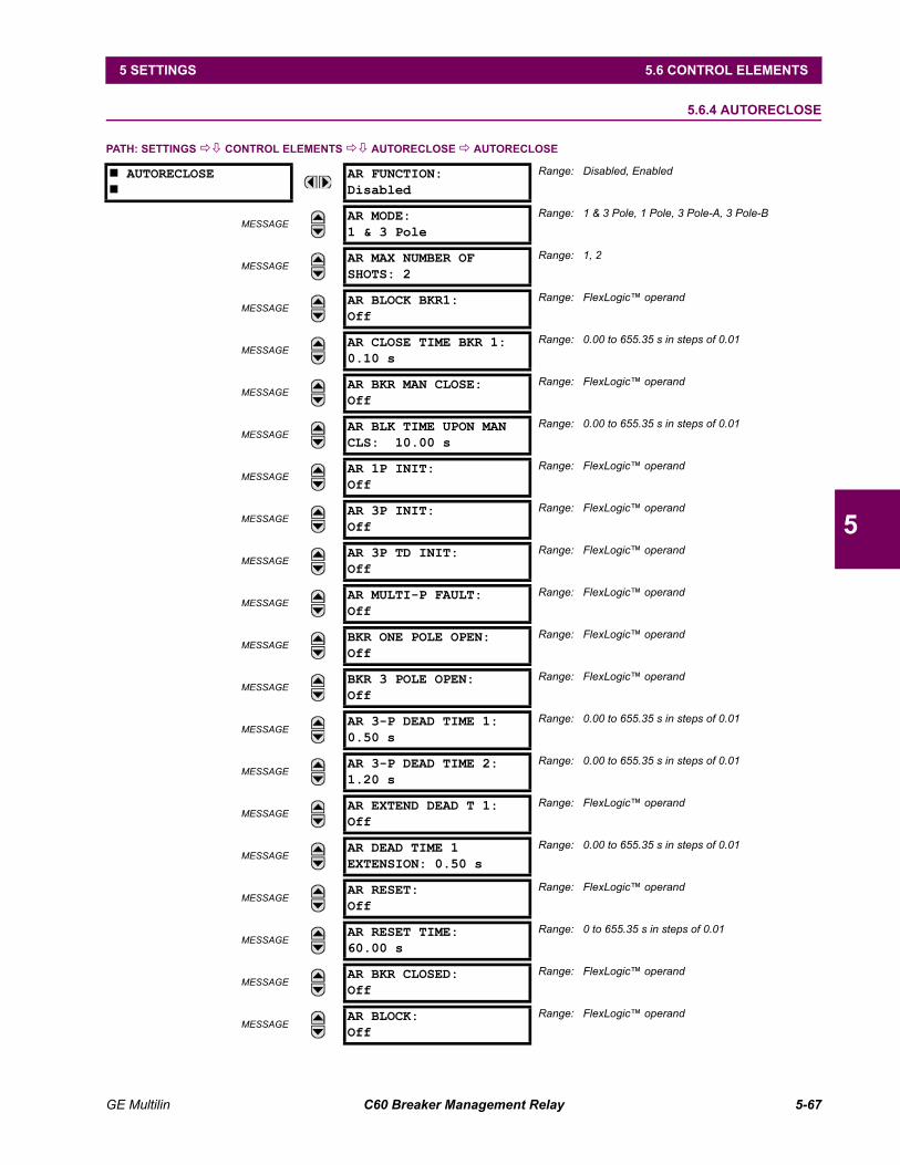
GE Multilin C60 Breaker Management Relay 5-67
5 SETTINGS 5.6 CONTROL ELEMENTS
5
5.6.4 AUTORECLOSE
PATH: SETTINGS !" CONTROL ELEMENTS !" AUTORECLOSE ! AUTORECLOSE
# AUTORECLOSE#
AR FUNCTION:Disabled
Range: Disabled, Enabled
MESSAGEAR MODE:1 & 3 Pole
Range: 1 & 3 Pole, 1 Pole, 3 Pole-A, 3 Pole-B
MESSAGEAR MAX NUMBER OFSHOTS: 2
Range: 1, 2
MESSAGEAR BLOCK BKR1:Off
Range: FlexLogic operand
MESSAGEAR CLOSE TIME BKR 1:0.10 s
Range: 0.00 to 655.35 s in steps of 0.01
MESSAGEAR BKR MAN CLOSE:Off
Range: FlexLogic operand
MESSAGEAR BLK TIME UPON MANCLS: 10.00 s
Range: 0.00 to 655.35 s in steps of 0.01
MESSAGEAR 1P INIT:Off
Range: FlexLogic operand
MESSAGEAR 3P INIT:Off
Range: FlexLogic operand
MESSAGEAR 3P TD INIT:Off
Range: FlexLogic operand
MESSAGEAR MULTI-P FAULT:Off
Range: FlexLogic operand
MESSAGEBKR ONE POLE OPEN:Off
Range: FlexLogic operand
MESSAGEBKR 3 POLE OPEN:Off
Range: FlexLogic operand
MESSAGEAR 3-P DEAD TIME 1:0.50 s
Range: 0.00 to 655.35 s in steps of 0.01
MESSAGEAR 3-P DEAD TIME 2:1.20 s
Range: 0.00 to 655.35 s in steps of 0.01
MESSAGEAR EXTEND DEAD T 1:Off
Range: FlexLogic operand
MESSAGEAR DEAD TIME 1EXTENSION: 0.50 s
Range: 0.00 to 655.35 s in steps of 0.01
MESSAGEAR RESET:Off
Range: FlexLogic operand
MESSAGEAR RESET TIME:60.00 s
Range: 0 to 655.35 s in steps of 0.01
MESSAGEAR BKR CLOSED:Off
Range: FlexLogic operand
MESSAGEAR BLOCK:Off
Range: FlexLogic operand
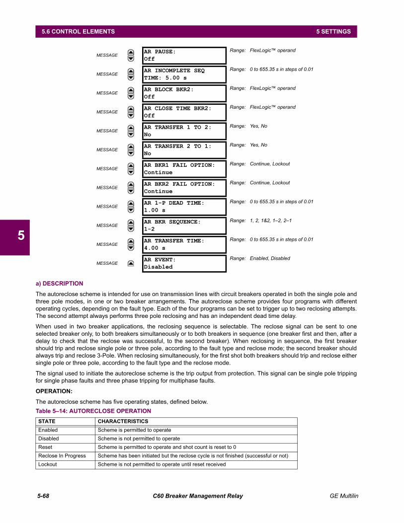
5-68 C60 Breaker Management Relay GE Multilin
5.6 CONTROL ELEMENTS 5 SETTINGS
5
a) DESCRIPTION
The autoreclose scheme is intended for use on transmission lines with circuit breakers operated in both the single pole andthree pole modes, in one or two breaker arrangements. The autoreclose scheme provides four programs with differentoperating cycles, depending on the fault type. Each of the four programs can be set to trigger up to two reclosing attempts.The second attempt always performs three pole reclosing and has an independent dead time delay.
When used in two breaker applications, the reclosing sequence is selectable. The reclose signal can be sent to oneselected breaker only, to both breakers simultaneously or to both breakers in sequence (one breaker first and then, after adelay to check that the reclose was successful, to the second breaker). When reclosing in sequence, the first breakershould trip and reclose single pole or three pole, according to the fault type and reclose mode; the second breaker shouldalways trip and reclose 3-Pole. When reclosing simultaneously, for the first shot both breakers should trip and reclose eithersingle pole or three pole, according to the fault type and the reclose mode.
The signal used to initiate the autoreclose scheme is the trip output from protection. This signal can be single pole trippingfor single phase faults and three phase tripping for multiphase faults.
OPERATION:
The autoreclose scheme has five operating states, defined below.
MESSAGEAR PAUSE:Off
Range: FlexLogic operand
MESSAGEAR INCOMPLETE SEQTIME: 5.00 s
Range: 0 to 655.35 s in steps of 0.01
MESSAGEAR BLOCK BKR2:Off
Range: FlexLogic operand
MESSAGEAR CLOSE TIME BKR2:Off
Range: FlexLogic operand
MESSAGEAR TRANSFER 1 TO 2:No
Range: Yes, No
MESSAGEAR TRANSFER 2 TO 1:No
Range: Yes, No
MESSAGEAR BKR1 FAIL OPTION:Continue
Range: Continue, Lockout
MESSAGEAR BKR2 FAIL OPTION:Continue
Range: Continue, Lockout
MESSAGEAR 1-P DEAD TIME:1.00 s
Range: 0 to 655.35 s in steps of 0.01
MESSAGEAR BKR SEQUENCE:1-2
Range: 1, 2, 1&2, 12, 21
MESSAGEAR TRANSFER TIME:4.00 s
Range: 0 to 655.35 s in steps of 0.01
MESSAGEAR EVENT:Disabled
Range: Enabled, Disabled
Table 514: AUTORECLOSE OPERATIONSTATE CHARACTERISTICSEnabled Scheme is permitted to operateDisabled Scheme is not permitted to operateReset Scheme is permitted to operate and shot count is reset to 0Reclose In Progress Scheme has been initiated but the reclose cycle is not finished (successful or not)Lockout Scheme is not permitted to operate until reset received
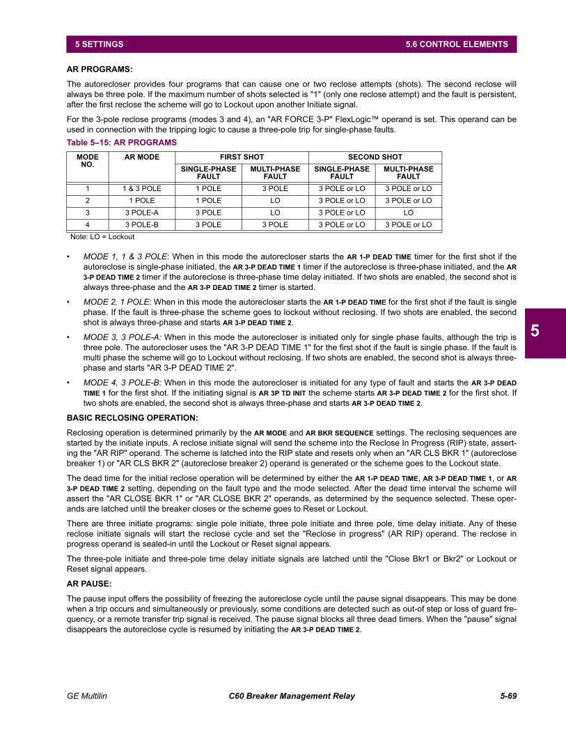
GE Multilin C60 Breaker Management Relay 5-69
5 SETTINGS 5.6 CONTROL ELEMENTS
5
AR PROGRAMS:
The autorecloser provides four programs that can cause one or two reclose attempts (shots). The second reclose willalways be three pole. If the maximum number of shots selected is "1" (only one reclose attempt) and the fault is persistent,after the first reclose the scheme will go to Lockout upon another Initiate signal.
For the 3-pole reclose programs (modes 3 and 4), an "AR FORCE 3-P" FlexLogic operand is set. This operand can beused in connection with the tripping logic to cause a three-pole trip for single-phase faults.
MODE 1, 1 & 3 POLE: When in this mode the autorecloser starts the AR 1-P DEAD TIME timer for the first shot if theautoreclose is single-phase initiated, the AR 3-P DEAD TIME 1 timer if the autoreclose is three-phase initiated, and the AR3-P DEAD TIME 2 timer if the autoreclose is three-phase time delay initiated. If two shots are enabled, the second shot isalways three-phase and the AR 3-P DEAD TIME 2 timer is started.
MODE 2, 1 POLE: When in this mode the autorecloser starts the AR 1-P DEAD TIME for the first shot if the fault is singlephase. If the fault is three-phase the scheme goes to lockout without reclosing. If two shots are enabled, the secondshot is always three-phase and starts AR 3-P DEAD TIME 2.
MODE 3, 3 POLE-A: When in this mode the autorecloser is initiated only for single phase faults, although the trip isthree pole. The autorecloser uses the "AR 3-P DEAD TIME 1" for the first shot if the fault is single phase. If the fault ismulti phase the scheme will go to Lockout without reclosing. If two shots are enabled, the second shot is always three-phase and starts "AR 3-P DEAD TIME 2".
MODE 4, 3 POLE-B: When in this mode the autorecloser is initiated for any type of fault and starts the AR 3-P DEADTIME 1 for the first shot. If the initiating signal is AR 3P TD INIT the scheme starts AR 3-P DEAD TIME 2 for the first shot. Iftwo shots are enabled, the second shot is always three-phase and starts AR 3-P DEAD TIME 2.
BASIC RECLOSING OPERATION:
Reclosing operation is determined primarily by the AR MODE and AR BKR SEQUENCE settings. The reclosing sequences arestarted by the initiate inputs. A reclose initiate signal will send the scheme into the Reclose In Progress (RIP) state, assert-ing the "AR RIP" operand. The scheme is latched into the RIP state and resets only when an "AR CLS BKR 1" (autoreclosebreaker 1) or "AR CLS BKR 2" (autoreclose breaker 2) operand is generated or the scheme goes to the Lockout state.
The dead time for the initial reclose operation will be determined by either the AR 1-P DEAD TIME, AR 3-P DEAD TIME 1, or AR3-P DEAD TIME 2 setting, depending on the fault type and the mode selected. After the dead time interval the scheme willassert the "AR CLOSE BKR 1" or "AR CLOSE BKR 2" operands, as determined by the sequence selected. These oper-ands are latched until the breaker closes or the scheme goes to Reset or Lockout.
There are three initiate programs: single pole initiate, three pole initiate and three pole, time delay initiate. Any of thesereclose initiate signals will start the reclose cycle and set the "Reclose in progress" (AR RIP) operand. The reclose inprogress operand is sealed-in until the Lockout or Reset signal appears.
The three-pole initiate and three-pole time delay initiate signals are latched until the "Close Bkr1 or Bkr2" or Lockout orReset signal appears.
AR PAUSE:
The pause input offers the possibility of freezing the autoreclose cycle until the pause signal disappears. This may be donewhen a trip occurs and simultaneously or previously, some conditions are detected such as out-of step or loss of guard fre-quency, or a remote transfer trip signal is received. The pause signal blocks all three dead timers. When the "pause" signaldisappears the autoreclose cycle is resumed by initiating the AR 3-P DEAD TIME 2.
Table 515: AR PROGRAMSMODE
NO.AR MODE FIRST SHOT SECOND SHOT
SINGLE-PHASE FAULT
MULTI-PHASE FAULT
SINGLE-PHASE FAULT
MULTI-PHASE FAULT
1 1 & 3 POLE 1 POLE 3 POLE 3 POLE or LO 3 POLE or LO2 1 POLE 1 POLE LO 3 POLE or LO 3 POLE or LO3 3 POLE-A 3 POLE LO 3 POLE or LO LO4 3 POLE-B 3 POLE 3 POLE 3 POLE or LO 3 POLE or LO
Note: LO = Lockout
5-70 C60 Breaker Management Relay GE Multilin
5.6 CONTROL ELEMENTS 5 SETTINGS
5
This feature can be also used when a transformer is tapped from the protected line and a reclose is not desirable until thetransformer is disconnected from the line. In this situation the reclose scheme will be "paused" until the transformer is dis-connected.
The AR PAUSE input will force a three-pole trip through the 3-P DEADTIME 2 path.
EVOLVING FAULTS:
8 ms after the single pole dead time has been initiated, the "AR FORCE 3P TRIP" operand is set and it will be reset onlywhen the scheme is reset or goes to Lockout. This will ensure that when a fault on one phase evolves to include anotherphase during the single pole dead time of the auto-recloser the scheme will force a 3 pole trip and reclose.
RECLOSING SCHEME OPERATION FOR ONE BREAKER:
Permanent Fault: Consider mode No.1 which calls for 1-Pole or 3-Pole time delay No. 1 for the first reclosure and 3-Pole time delay No. 2 for the second reclosure, and assume a permanent fault on the line. Also assume the scheme isin the Reset state. For the first single-phase fault the AR 1-P DEAD TIME timer will be started, while for the first multi-phase fault the AR 3-P DEAD TIME 1 timer will be started. If the AR 3P TD INIT signal is high, the AR 3-P DEAD TIME 2 will bestarted for the first shot.
If AR MAX NO OF SHOTS is set to "1", upon the first reclose the shot counter is set to 1. Upon reclosing, the fault is againdetected by protection and reclose is initiated. The breaker is tripped three-pole through the "AR SHOT COUNT >0"that will set the "AR FORCE 3P" operand. Because the shot counter has reached the maximum number of shots per-mitted the scheme is sent to the Lockout state.
If AR MAX NO OF SHOTS is set to "2", upon the first reclose the shot counter is set to 1. Upon reclosing, the fault is againdetected by protection and reclose is initiated. The breaker is tripped three-pole through the "AR SHOT COUNT >0"that will set the "AR FORCE 3P" operand. After the second reclose the shot counter is set to 2. Upon reclosing, thefault is again detected by protection, the breaker is tripped three-pole, and reclose is initiated again. Because the shotcounter has reached the maximum number of shots permitted the scheme is sent to the lockout state.
Transient Fault: When a reclose output signal is sent to close the breaker the reset timer is started. If the reclosuresequence is successful (there is no initiating signal and the breaker is closed) the reset timer will time out returning thescheme to the reset state with the shot counter set to "0" making it ready for a new reclose cycle.
RECLOSING SCHEME OPERATION FOR TWO BREAKERS:
Permanent Fault: The general method of operation is the same as that outlined for the one breaker applicationsexcept for the following description, which assumes AR BKR SEQUENCE is set to "1-2" (reclose breaker 1 before breaker2.) The signal output from the dead time timers passes through the breaker selection logic to initiate reclosing ofBreaker 1. The close breaker 1 signal will initiate the Transfer Timer. After the reclose of the first breaker the fault isagain detected by the protection, the breaker is tripped three pole and the autoreclose scheme is initiated. The Initiatesignal will stop the transfer timer. After the 3-P dead time times out the close breaker 1 signal will close first breakeragain and will start the transfer timer. Since the fault is permanent the protection will trip again initiating the autoreclosescheme that will be sent to Lockout by the "Shot Count = Max" signal.
Transient Fault: When the first reclose output signal is sent to close breaker 1, the reset timer is started. The closebreaker 1 signal initiates the transfer timer that times out and sends the close signal to the second breaker. If the reclo-sure sequence is successful (both breakers are closed and there is no initiating signal) the reset timer will time out,returning the scheme to the reset state with the shot counter set to 0. The scheme will be ready for a new reclosecycle.
AR BKR1(2) RECLS FAIL:
If the selected sequence is "12" or "21" and after the first or second reclose attempt the breaker fails to close, there aretwo options. If the AR BKR 1(2) FAIL OPTION is set to "Lockout", the scheme will go to lockout state. If the AR BKR 1(2) FAILOPTION is set to "Continue", the reclose process will continue with Breaker No. 2. At the same time the shot counter will bedecreased (since the closing process was not completed).
SCHEME RESET AFTER RECLOSURE:
When a reclose output signal is sent to close either breaker 1 or 2 the reset timer is started. If the reclosure sequence issuccessful (there is no initiating signal and the breakers are closed) the reset timer will time out, returning the scheme tothe reset state, with the shot counter set to 0, making it ready for a new reclose cycle.
GE Multilin C60 Breaker Management Relay 5-71
5 SETTINGS 5.6 CONTROL ELEMENTS
5
In two breaker schemes, if one breaker is in the OUT OF SERVICE state and the other is closed at the end of the resettime, the scheme will also reset. If at the end of the reset time at least one breaker, which is not in the OUT OF SERVICEstate, is open the scheme will be sent to Lockout.
The reset timer will be stopped if the reclosure sequence is not successful: an initiating signal is present or the scheme is inthe Lockout state. The reset timer will also be stopped if the breaker is manually closed or the scheme is otherwise resetfrom lockout.
LOCKOUT:
When a reclose sequence is started by an initiate signal the scheme moves into the Reclose In Progress state and startsthe Incomplete Sequence Timer. The setting of this timer determines the maximum time interval allowed for a single recloseshot. If a close breaker 1 or 2 signal is not present before this time expires, the scheme goes to "Lockout".
There are four other conditions that can take the scheme to the Lockout state, as shown below:
Receipt of "Block" input while in the Reclose in Progress state
The reclosing program logic: when a 3P Initiate is present and the autoreclose mode is either 1 Pole or 3Pole-A (3 poleautoreclose for single pole faults only)
Initiation of the scheme when the count is at the maximum allowed
If at the end of the reset time at least one breaker, which is not in the OUT OF SERVICE state, is open the scheme willbe sent to Lockout. The scheme will be also sent to Lockout if one breaker fails to reclose and the setting AR BKR FAILOPTION is set to "Lockout".
Once the Lockout state is set it will be latched in until the scheme is intentionally reset from Lockout or a breaker is manu-ally closed.
BREAKER OPEN BEFORE FAULT:
A logic circuit is provided that inhibits the close breaker 1(2) output if a reclose initiate (RIP) indicator is not present within30 ms of the "Breaker any phase open" input. This feature is intended to prevent reclosing if one of the breakers was openin advance of a reclose initiate input to the recloser. This logic circuit resets when the breaker is closed.
TRANSFER RECLOSE WHEN BREAKER IS BLOCKED:
1. When the reclosing sequence 1-2 is selected and breaker No. 1 is blocked (AR BKR1 BLK operand is set) the reclosesignal can be transferred direct to the breaker No. 2 if AR TRANSFER 1 TO 2 is set to "Yes". If set to "No", the scheme willbe sent to LOCKOUT by the incomplete sequence timer.
2. When the reclosing sequence 2-1 is selected and breaker No. 2 is blocked (AR BKR2 BLK operand is set) the reclosesignal can be transferred direct to the breaker No.1 if AR TRANSFER 2 TO 1 is set to "YES". If set to "NO" the scheme willbe sent to LOCKOUT by the incomplete sequence timer.
FORCE 3-POLE TRIPPING:
The reclosing scheme contains logic that is used to signal trip logic that three-pole tripping is required for certain conditions.This signal is activated by any of the following:
Autoreclose scheme is Disabled.
Autoreclose scheme is in the Lockout state.
Autoreclose mode is programmed for three-pole operation
The shot counter is not at 0, i.e. the scheme is not in the Reset state. This ensures a second trip will be three-polewhen reclosing onto a permanent single phase fault.
8 ms after the single-pole reclose is initiated by the AR 1P INIT signal.
ZONE 1 EXTENT:
"Extended Zone 1" is 0 when the AR is in LO or Disabled and 1 when the AR is in Reset.
1. When "Extended Zone 1" is 0, the distance functions shall be set to normal underreach Zone 1 setting.
2. When "Extended Zone 1" is 1, the distance functions may be set to Extended Zone 1 Reach, which is an overreachingsetting.
3. During a reclose cycle, "Extended Zone 1" goes to 0 as soon as the first CLOSE BREAKER signal is issued (AR SHOTCOUNT > 0) and remains 0 until the recloser goes back to Reset.
5-72 C60 Breaker Management Relay GE Multilin
5.6 CONTROL ELEMENTS 5 SETTINGS
5
b) USE OF SETTINGS
AR MODE: This setting selects the AR operating mode, which functions in conjunction with signals received at the initiationinputs as described previously.
AR MAX NUMBER OF SHOTS: This setting specifies the number of reclosures that can be attempted before reclosuregoes to Lockout when the fault is permanent.
AR BLOCK BKR1: This input selects an operand that will block the reclose command for breaker No.1. This condition canbe for example: breaker low air pressure, reclose in progress on another line (for the central breaker in a breaker and a halfarrangement), or a sum of conditions combined in FlexLogic.
AR CLOSE TIME BKR1:This setting represents the closing time for the breaker No. 1 from the moment the "Close" com-mand is sent to the moment the contacts are closed.
AR BKR MAN CLOSE: This setting selects a FlexLogic operand that represents manual close command to a breakerassociated with the autoreclose scheme
AR BLK TIME UPON MAN CLS: The autoreclose scheme can be disabled for a programmable time delay after an associ-ated circuit breaker is manually commanded to close, preventing reclosing onto an existing fault such as grounds on theline. This delay must be longer than the slowest expected trip from any protection not blocked after manual closing. If theautoreclose scheme is not initiated after a manual close and this time expires the autoreclose scheme is set to the Resetstate.
AR 1P INIT: This setting selects a FlexLogic operand that is intended to initiate single Pole autoreclosure.
AR 3P INIT: This setting selects a FlexLogic operand that is intended to initiate three Pole autoreclosure, first timer (AR3P DEAD TIME 1) that can be used for a high-speed autoreclosure.
AR 3P TD INIT: This setting selects a FlexLogic operand that is intended to initiate three Pole autoreclosure, secondtimer (AR 3P DEAD TIME 2) that can be used for a time-delay autoreclosure.
AR MULTI-P FAULT: This setting selects a FlexLogic operand that indicates a multi-phase fault. The operand valueshould be zero for single-phase to ground faults.
BKR ONE POLE OPEN: This setting selects a FlexLogic operand which indicates that the breaker(s) has opened cor-rectly following a single phase to ground fault and the autoreclose scheme can start timing the single pole dead time (for 1-2 reclose sequence for example, breaker No. 1 should trip single pole and breaker No. 2 should trip 3 pole).
The scheme has a pre-wired input that indicates breaker(s) status.
BKR 3 POLE OPEN: This setting selects a FlexLogic operand which indicates that the breaker(s) has opened three poleand the autoreclose scheme can start timing the three pole dead time.
The scheme has a pre-wired input that indicates breaker(s) status.
AR 3-P DEAD TIME 1: This is the dead time following the first three pole trip. This intentional delay can be used for a high-speed three-pole autoreclose. However, it should be set longer than the estimated de-ionizing time following the three-poletrip.
AR 3-P DEAD TIME 2: This is the dead time following the second three-pole trip or initiated by the AR 3P TD INIT input.This intentional delay is typically used for a time delayed three-pole autoreclose (as opposed to high speed three-poleautoreclose).
AR EXTEND DEAD T 1: This setting selects an operand that will adapt the duration of the dead time for the first shot to thepossibility of non-simultaneous tripping at the two line ends. Typically this is the operand set when the communicationchannel is out of service
AR DEAD TIME 1 EXTENSION: This timer is used to set the length of the dead time 1 extension for possible non-simulta-neous tripping of the two ends of the line.
AR RESET: This setting selects the operand that forces the autoreclose scheme from any state to Reset. Typically this is amanual reset from lockout, local or remote.
AR RESET TIME: A reset timer output resets the recloser following a successful reclosure sequence. The setting is basedon the breaker time which is the minimum time required between successive reclose sequences.
AR BKR CLOSED: This setting selects an operand that indicates that the breaker(s) are closed at the end of the reset timeand the scheme can reset.
GE Multilin C60 Breaker Management Relay 5-73
5 SETTINGS 5.6 CONTROL ELEMENTS
5
AR BLOCK: This setting selects the operand that blocks the Autoreclose scheme (it can be a sum of conditions such as:Time Delayed Tripping, Breaker Failure, Bus Differential Protection, etc.). If the block signal is present before autoreclosescheme initiation the AR DISABLED FlexLogic operand will be set. If the block signal occurs when the scheme is in theRIP state the scheme will be sent to Lockout.
AR PAUSE: The pause input offers the ability to freeze the autoreclose cycle until the pause signal disappears. This maybe done when a trip occurs and simultaneously or previously, some conditions are detected such as out-of step or loss ofguard frequency, or a remote transfer trip signal is received. When the "pause" signal disappears the autoreclose cycle isresumed. This feature can also be used when a transformer is tapped from the protected line and a reclose is not desirableuntil the it is disconnected from the line. In this situation, the reclose scheme is "paused" until the transformer is discon-nected.
AR INCOMPLETE SEQ TIME: This timer is used to set the maximum time interval allowed for a single reclose shot. It isstarted whenever a reclosure is initiated and is active until the CLOSE BKR1 or BKR2 signal is sent. If all conditions allow-ing a breaker closure are not satisfied when this time expires, the scheme goes to "Lockout". The minimum permissible set-ting is established by the "3-P Dead Time 2" timer setting. Settings beyond this will determine the "wait" time for the breakerto open so that the reclose cycle can continue and/or for the AR PAUSE signal to reset and allow the reclose cycle to con-tinue and/or for the AR BKR1(2) BLK signal to disappear and allow the AR CLOSE BKR1(2) signal to be sent.
AR BLOCK BKR2: This input selects an operand that will block the reclose command for breaker No.2. This condition canbe for example: breaker low air pressure, reclose in progress on another line (for the central breaker in a breaker and a halfarrangement), or a sum of conditions combined in FlexLogic.
AR BKR2 MNL CLOSE: This setting selects an operand asserted when breaker No. 2 is manually commanded to close.
AR CLOSE TIME BKR2: This setting represents the closing time for the breaker No. 2 from the moment the "Close" com-mand is sent to the moment the contacts are closed.
AR TRANSFER 1 TO 2: This setting establishes how the scheme performs when the breaker closing sequence is 1-2 andbreaker No. 1 is blocked. When set to "YES" the closing command will be transferred direct to breaker No. 2 without waitingthe transfer time. When set to "NO" the closing command will be blocked by the AR BKR1 BLK signal and the scheme willbe sent to LOCKOUT by the incomplete sequence timer.
AR TRANSFER 2 TO 1: This setting establishes how the scheme performs when the breaker closing sequence is 2-1 andbreaker No. 2 is blocked. When set to "YES" the closing command will be transferred direct to breaker No. 1 without waitingthe transfer time. When set to "NO" the closing command will be blocked by the AR BKR2 BLK signal and the scheme willbe sent to LOCKOUT by the incomplete sequence timer.
AR BKR1 FAIL OPTION: This setting establishes how the scheme performs when the breaker closing sequence is 1-2 andbreaker No. 1 has failed to close. When set to "Continue" the closing command will be transferred to breaker No. 2 whichwill continue the reclosing cycle until successful (the scheme will reset) or unsuccessful (the scheme will go to Lockout).When set to "Lockout" the scheme will go to lockout without attempting to reclose breaker No. 2.
AR BKR2 FAIL OPTION: This setting establishes how the scheme performs when the breaker closing sequence is 2-1 andbreaker No. 2 has failed to close. When set to "Continue" the closing command will be transferred to breaker No. 1 whichwill continue the reclosing cycle until successful (the scheme will reset) or unsuccessful (the scheme will go to Lockout).When set to "Lockout" the scheme will go to lockout without attempting to reclose breaker No. 1.
AR 1-P DEAD TIME: Set this intentional delay longer than the estimated de-ionizing time following the first single-pole trip.
AR BREAKER SEQUENCE: This setting selects the breakers reclose sequence:
1 = reclose breaker 1 only2 = reclose breaker 2 only1&2 = reclose both breakers simultaneously1-2 = reclose breakers sequentially; breaker No. 1 first2-1 = reclose breakers sequentially; breaker No. 2 first
AR TRANSFER TIME: The transfer time is used only for breaker closing sequence 1-2 or 2-1, when the two breakers arereclosed sequentially. The transfer timer is initiated by a close signal to the first breaker. The transfer timer transfers thereclose signal from the breaker selected to close first to the second breaker. The time delay setting is based on the maxi-mum time interval between the autoreclose signal and the protection trip contact closure assuming a permanent fault(unsuccessful reclose). Therefore, the minimum setting is equal to the maximum breaker closing time plus the maximumline protection operating time plus a suitable margin. This setting will prevent the autoreclose scheme from transferring theclose signal to the second breaker unless a successful reclose of the first breaker occurs.

5-74 C60 Breaker Management Relay GE Multilin
5.6 CONTROL ELEMENTS 5 SETTINGS
5
For correct operation of the autoreclose scheme, the Breaker Control feature must be enabled and config-ured properly. When the breaker reclose sequence is "1-2" or "2-1" the breaker that will reclose second insequence (breaker No. 2 for sequence 1-2 and breaker No. 1 for sequence 2-1) must be configured to tripthree-pole for any type of fault
Figure 528: SINGLE-POLE AUTORECLOSE LOGIC (SHEET 1 OF 3)
NOTE
FLEX
LOG
IC O
PERA
ND
FLEX
LOG
IC O
PERA
ND
FLEX
LOG
IC O
PERA
ND
FLEX
LOG
IC O
PERA
ND
FLEX
LOG
IC O
PERA
ND
AR
3-P/
2 RI
P
SETT
ING
SETT
ING
OR
AN
D
AND
OR
OR
OR
OR OR
OR
OR
AN
D
OR
AN
D
AN
D
AN
D
AN
D
AN
D
OR
OR
AR
INCO
MPL
ETE
SEQ
.TI
MER
:
AR
LO
AR
INCO
MPL
ETE
SEQ
AR
FORC
E 3P
TRI
P
AR
ZON
E 1
EXTE
NT
RESE
T (to
she
et 2
)
8270
89A
C.CD
R
AR
3-P
DEA
D T
IME
2:
0 0
OR
OR
SETT
ING
SETT
ING
Off
= 0
AN
D
OR
OR
AR
EXTE
ND
DEA
D T
IME
1:
CLO
SE (t
o pa
ge 2
)
AR
DEA
D T
IME
1EX
TEN
SIO
N:
0
(To
page
2, R
eset
AR
TRA
NSF
ER T
IMER
)
To: A
R FO
RCE
3P T
RIP
(Evo
lvin
g fa
ult)
AR
INIT
IATE
Evol
ving
faul
t
BKR
FA
IL T
O R
ECLS
(from
she
et 2
)
S R
Latc
h
AR
DIS
AB
LED
FLEX
LOG
IC O
PERA
ND
FLEX
LOG
IC O
PERA
ND
FLEX
LOG
IC O
PERA
ND
S
AR
1-P
RIP
AR
3-P/
1 RI
P
AR
ENA
BLE
D
AR
DIS
AB
LED
SETT
ING
SETT
ING
LO
OR
OR
OR
AN
D
OR
AN
D
AN
D
AND
AND
AND
OR
OR
OR
AN
D
AN
D
AR
3-P
DEA
D T
IME
1:
AR
1-P
DEA
D T
IME:
0 0
SETT
ING
0AR
BLK
TIM
E U
PON
MA
NCL
S :
FLEX
LOG
IC O
PERA
ND
AR
RIP
S
S
S
R
R
R
Latc
h
Latc
h
Latc
h
0.5
cycl
e
0
FLEX
LOG
IC O
PERA
ND
FLEX
LOG
IC O
PERA
ND
SETT
ING
AR
SHO
T CO
UN
T>0
PHA
SE S
ELEC
T M
ULT
I-P
D60
Rel
ay O
nly
From
Pha
se S
elec
tor
AR
PAU
SE
SETT
ING
SETT
ING
SETT
ING
SETT
ING
SETT
ING
BKR
ON
E PO
LE O
PEN
:
BKR
3 P
OLE
OPE
N:
AR
RESE
T:
AR
MU
LTI-
P FA
ULT
:
AR
M0D
E:
Off
= 0
Off
= 0
Off
= 0
Off
= 0
Off
= 0
1 &
3 P
ole
1 Po
le
3 Po
le -
A3
Pole
-B
OR
OR
SHO
T CO
UN
T =
MA
X
CLO
SE B
KR1
OR
BKR
2RE
SET
BKR
ON
E PO
LE O
PEN
BKR
3 P
OLE
OPE
N
From sheet 3D60 Relay Only From Trip Output
D60
Rel
ay O
nly
From Sheet 2
FLEX
LOG
IC O
PERA
ND
FLEX
LOG
IC O
PERA
ND
SETT
ING
TRIP
1-P
OLE
LIN
E PI
CKU
P O
P
TRIP
AR
INIT
3-P
OLE
AR
3P T
D IN
IT:
SETT
ING
SETT
ING
SETT
ING
SETT
ING
Enab
le=1
Dis
able
=0
AR
FUN
CTIO
N:
AR
BLO
CK:
AR
BKR
MA
N C
LOSE
:
BKR
MA
NU
AL
CLO
SE:
AR
1P IN
IT:
Off
= 0
Off
= 0
Off
= 0
SETT
ING
AR
3P IN
IT:
Off
= 0
Off
= 0
OR
(Fro
m s
heet
3)
FLEX
LOG
IC O
PERA
ND
5ms
0
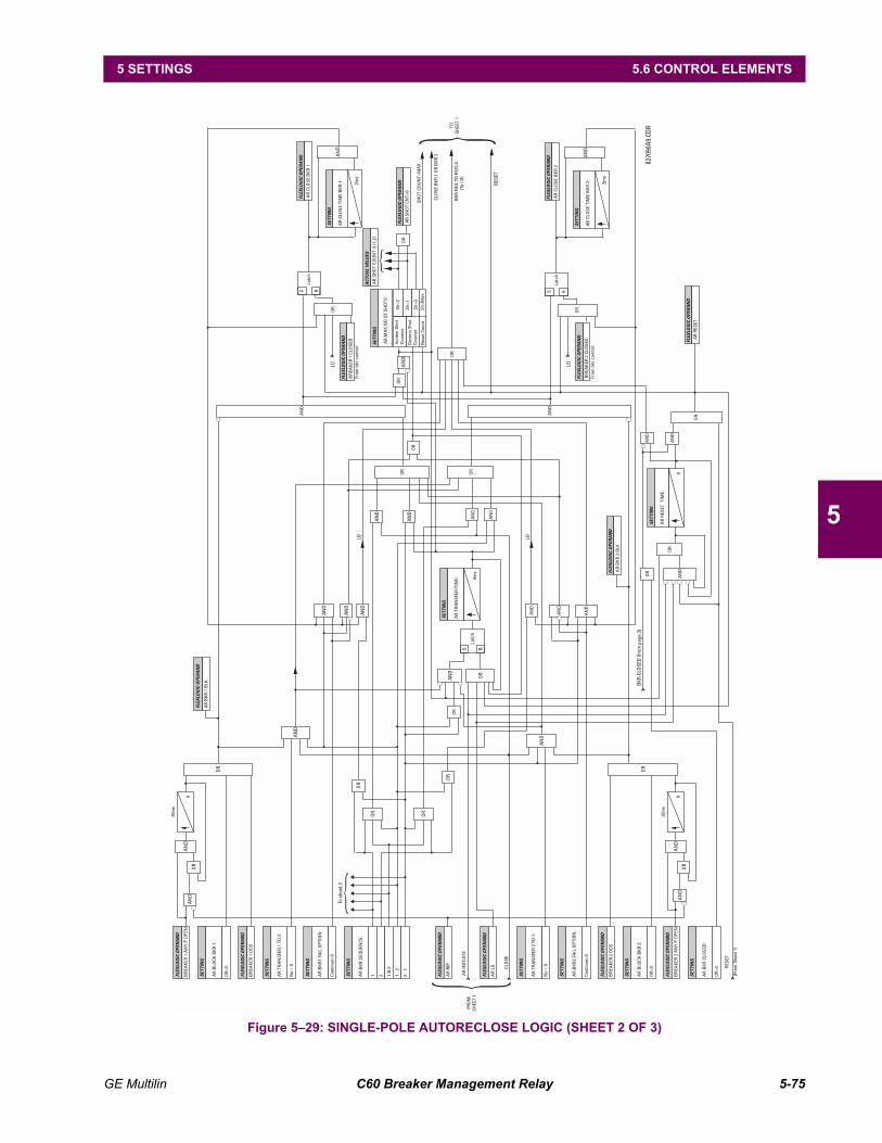
GE Multilin C60 Breaker Management Relay 5-75
5 SETTINGS 5.6 CONTROL ELEMENTS
5
Figure 529: SINGLE-POLE AUTORECLOSE LOGIC (SHEET 2 OF 3)
FLEX
LOG
IC O
PERA
ND
FLEX
LOG
IC O
PERA
ND
FLEX
LOG
IC O
PERA
ND
FLEX
LOG
IC O
PERA
ND
ACT
UA
L VA
LUES
FLEX
LOG
IC O
PERA
ND
FLEX
LOG
IC O
PERA
ND
FLEX
LOG
IC O
PERA
ND
FLEX
LOG
IC O
PERA
ND
FLEX
LOG
IC O
PERA
ND
FLEX
LOG
IC O
PERA
ND
AR
CLO
SE
BK
R 2
AR
CLO
SE
BK
R 1
BR
EAK
ER 1
CLO
SED
From
bkr
con
trol
From
bkr
con
trol
BR
EAK
ER 2
CLO
SED
AR
SH
OT
CO
UN
T: 0
(1,2
)
SH
OT
CO
UN
T=M
AX
CLO
SE
BK
R 1
OR
BK
R 2
BK
R F
AIL
TO
REC
LS(T
o LO
)
AR
SH
OT
CN
T>0
AR
BK
R 2
BLK
BR
EAK
ER 1
AN
Y P
OP
EN
AR
BK
R 1
BLK
SETT
ING
SETT
ING
AR
CLO
SE
TIM
E B
KR
2:
AR
CLO
SE
TIM
E B
KR
1:
SETT
ING
AR
MA
X N
O O
F S
HO
TS:
Incr
em S
hot
Cou
nter
Dec
rem
Sho
tC
ount
er
Sh=
2
Sh=
1
Sh=
0S
h=M
axR
eset
Cou
nt
SETT
ING
SETT
ING
SETT
ING
SETT
ING
SETT
ING
SETT
ING
SETT
ING
SETT
ING
SETT
ING
AN
D
AN
D
AN
D
AN
D
OR
OR
OR
OR
OR
AN
D
OR
OR
OR
OR
AN
D
AN
D
AR
BLO
CK
BK
R 1
:
AR
BLO
CK
BK
R 2
:
AR
BK
R C
LOS
ED:
30m
s
30m
s
AR
TR
AN
SFE
R T
IME:
AR
BK
R S
EQU
ENC
E:
BR
EAK
ER 1
OO
S
BR
EAK
ER 2
OO
S
AR
LO
AR
RIP
AR
RES
ET
AR
BK
R1
FAIL
OP
TIO
N:
Con
tinue
=0
AN
D
AR
BK
R2
FAIL
OP
TIO
N:
Con
tinue
=0
No
= 0
No
= 0
AR
TR
AN
SFE
R 1
TO
2:
AR
TR
AN
SFE
R 2
TO
1:
1 1 -
2
1 &
2
AR
INIT
IATE
FRO
MS
HEE
T 1
TOS
HEE
T 1
(Fro
m S
heet
1)
CLO
SE
RES
ET
2 2 -
1
Off=
0
Off=
0
Off=
0
SETT
ING
OR
OR
AN
D
AN
D
AN
D
AR
RES
ET T
IME:
OR
0ms
0
BKR
CLO
SED
(fro
m p
age
3)
RESE
T
To s
heet
3LO LO
LO LO
AN
D
AN
D
8270
90A
9.CD
R
SS RR
Latc
h
Latc
h
2ms
2ms
0 0
OR
OR
OR
OR
S RO
R
Latc
h
AN
D AN
D
AN
D
AN
D
OR
OR
OR
AN
D
AN
D
AN
D
AN
D
AN
D
AN
D
OR
AN
D
AN
D
FLEX
LOG
IC O
PERA
ND
FLEX
LOG
IC O
PERA
ND
FLEX
LOG
IC O
PERA
ND
FLEX
LOG
IC O
PERA
ND
BR
EAK
ER 2
AN
Y P
OP
EN

5-76 C60 Breaker Management Relay GE Multilin
5.6 CONTROL ELEMENTS 5 SETTINGS
5
Figure 530: SINGLE-POLE AUTORECLOSE LOGIC (SHEET 3 OF 3)827833A8.CDR
From sheet 2
FromBreaker ControlScheme
FromBreaker ControlScheme
AR BKR SEQUENCE:1
2
1&2
1-2
2-1
BREAKER 1 CLOSED
BREAKER 1 OPEN
BREAKER 2 OPEN
BREAKER 1 ONE P OPEN
BREAKER 2 ONE P OPEN
BREAKER 2 CLOSED
BREAKER 1 MNL CLS
BREAKER 1 OOS
BREAKER 2 OOS
FLEXLOGIC OPERAND
FLEXLOGIC OPERAND
FLEXLOGIC OPERAND
BREAKER 2 MNL CLS
FLEXLOGIC OPERAND
FLEXLOGIC OPERAND
FLEXLOGIC OPERAND
OR
AND
AND
AND
AND
AND
AND
AND
AND
AND
AND
AND
AND
AND
AND
AND
OR
OR
OR
OR
OR
OR
OR
OR
OR
OR
BKR MANUAL CLOSE(To sheet 1)
BKR CLOSED(To sheet 2)
BKR 3 POLE OPEN(To sheet 1)
BKR ONE POLE OPEN(To sheet 1)
FLEXLOGIC OPERAND
FLEXLOGIC OPERAND
FLEXLOGIC OPERAND
FLEXLOGIC OPERAND
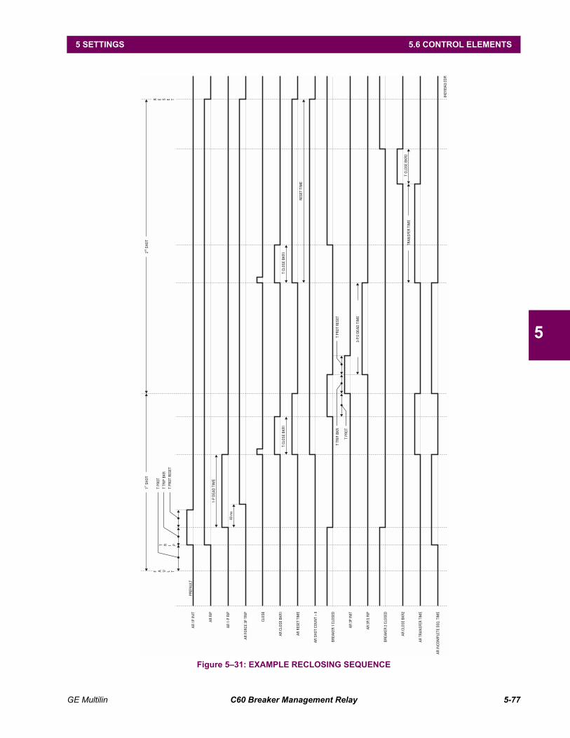
GE Multilin C60 Breaker Management Relay 5-77
5 SETTINGS 5.6 CONTROL ELEMENTS
5
Figure 531: EXAMPLE RECLOSING SEQUENCE
AR
1P IN
ITPR
EFA
ULT
F A U L T
R E S E T
1SH
OT
ST2
SHO
TN
D
T PR
OT
T TR
IP B
KR
T PR
OT
RESE
T
T R I P
AR
RIP
AR
1-P
RIP
AR
FORC
E 3P
TRI
P
CLO
SE
AR
CLO
SE B
KR1
T CL
OSE
BKR
1
T TR
IP B
KRT
PRO
T RE
SET
3-P/
2 D
EAD
TIM
E
TRA
NSF
ER T
IME
T CL
OSE
BKR
2
8427
03A
3.CD
R
T PR
OT
T CL
OSE
BKR
1
RESE
T TI
ME
AR
RESE
T TI
ME
AR
SHO
T CO
UN
T >
0
BRE
AKE
R 1
CLO
SED
AR
3P IN
IT
AR
3P/2
RIP
BRE
AKE
R 2
CLO
SED
AR
CLO
SE B
KR2
AR
TRA
NSF
ER T
IME
AR
INCO
MPL
ETE
SEQ
. TIM
E
1-P
DEA
D T
IME
40 m
s
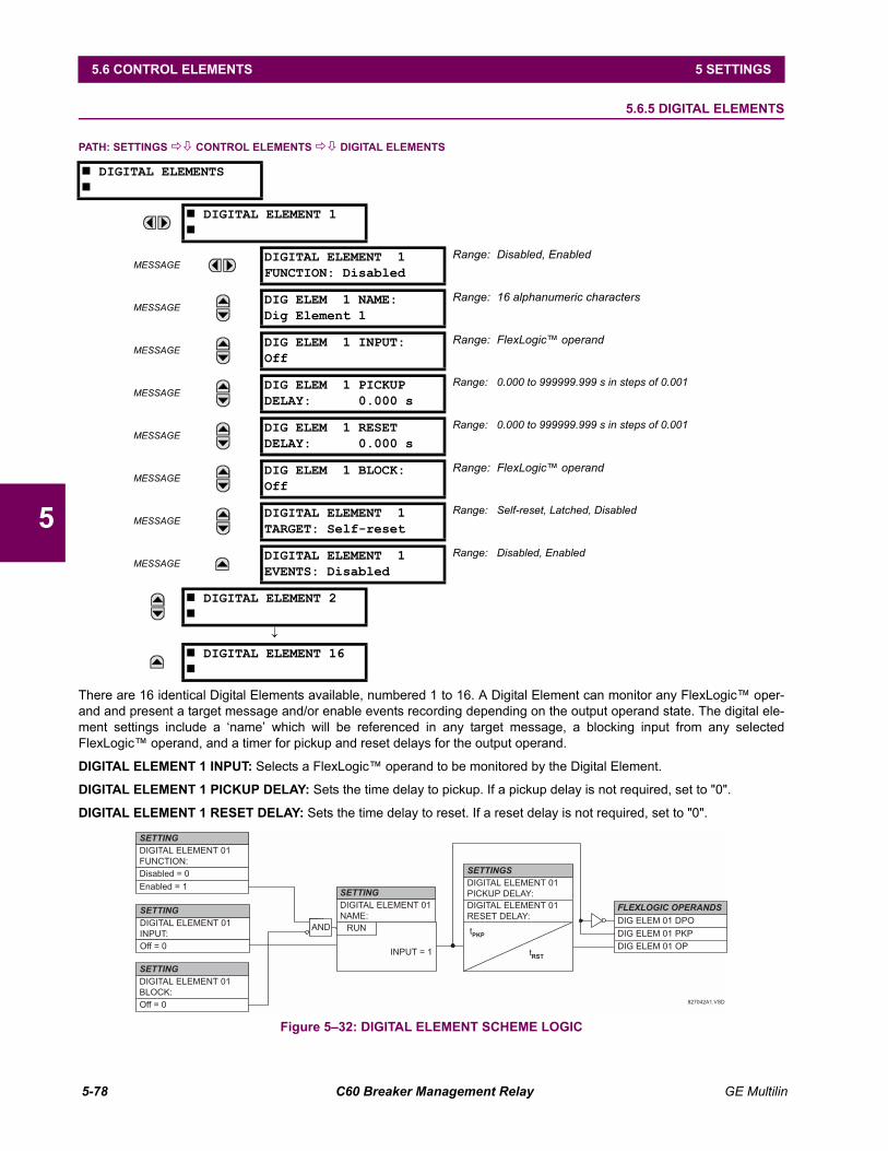
5-78 C60 Breaker Management Relay GE Multilin
5.6 CONTROL ELEMENTS 5 SETTINGS
5
5.6.5 DIGITAL ELEMENTS
PATH: SETTINGS !" CONTROL ELEMENTS !" DIGITAL ELEMENTS
There are 16 identical Digital Elements available, numbered 1 to 16. A Digital Element can monitor any FlexLogic oper-and and present a target message and/or enable events recording depending on the output operand state. The digital ele-ment settings include a name which will be referenced in any target message, a blocking input from any selectedFlexLogic operand, and a timer for pickup and reset delays for the output operand.
DIGITAL ELEMENT 1 INPUT: Selects a FlexLogic operand to be monitored by the Digital Element.
DIGITAL ELEMENT 1 PICKUP DELAY: Sets the time delay to pickup. If a pickup delay is not required, set to "0".
DIGITAL ELEMENT 1 RESET DELAY: Sets the time delay to reset. If a reset delay is not required, set to "0".
Figure 532: DIGITAL ELEMENT SCHEME LOGIC
# DIGITAL ELEMENTS#
# DIGITAL ELEMENT 1#
MESSAGEDIGITAL ELEMENT 1FUNCTION: Disabled
Range: Disabled, Enabled
MESSAGEDIG ELEM 1 NAME:Dig Element 1
Range: 16 alphanumeric characters
MESSAGEDIG ELEM 1 INPUT:Off
Range: FlexLogic operand
MESSAGEDIG ELEM 1 PICKUPDELAY: 0.000 s
Range: 0.000 to 999999.999 s in steps of 0.001
MESSAGEDIG ELEM 1 RESETDELAY: 0.000 s
Range: 0.000 to 999999.999 s in steps of 0.001
MESSAGEDIG ELEM 1 BLOCK:Off
Range: FlexLogic operand
MESSAGEDIGITAL ELEMENT 1TARGET: Self-reset
Range: Self-reset, Latched, Disabled
MESSAGEDIGITAL ELEMENT 1EVENTS: Disabled
Range: Disabled, Enabled
# DIGITAL ELEMENT 2#
↓
# DIGITAL ELEMENT 16#
SETTING
DIGITAL ELEMENT 01
FUNCTION:
Disabled = 0
Enabled = 1
DIGITAL ELEMENT 01
BLOCK:
Off = 0
FLEXLOGIC OPERANDS
DIG ELEM 01 DPO
DIG ELEM 01 PKP
SETTING
827042A1.VSD
DIGITAL ELEMENT 01
INPUT:
Off = 0
SETTING
INPUT = 1
RUN tPKP
tRST
DIGITAL ELEMENT 01
PICKUP DELAY:
SETTINGS
DIGITAL ELEMENT 01
RESET DELAY:
AND
SETTING
DIGITAL ELEMENT 01
NAME:
DIG ELEM 01 OP
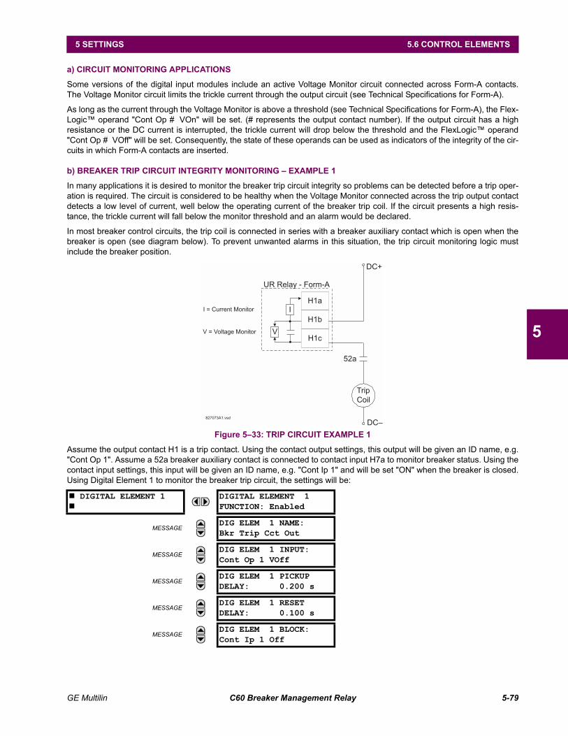
GE Multilin C60 Breaker Management Relay 5-79
5 SETTINGS 5.6 CONTROL ELEMENTS
5
a) CIRCUIT MONITORING APPLICATIONS
Some versions of the digital input modules include an active Voltage Monitor circuit connected across Form-A contacts.The Voltage Monitor circuit limits the trickle current through the output circuit (see Technical Specifications for Form-A).
As long as the current through the Voltage Monitor is above a threshold (see Technical Specifications for Form-A), the Flex-Logic operand "Cont Op # VOn" will be set. (# represents the output contact number). If the output circuit has a highresistance or the DC current is interrupted, the trickle current will drop below the threshold and the FlexLogic operand"Cont Op # VOff" will be set. Consequently, the state of these operands can be used as indicators of the integrity of the cir-cuits in which Form-A contacts are inserted.
b) BREAKER TRIP CIRCUIT INTEGRITY MONITORING EXAMPLE 1
In many applications it is desired to monitor the breaker trip circuit integrity so problems can be detected before a trip oper-ation is required. The circuit is considered to be healthy when the Voltage Monitor connected across the trip output contactdetects a low level of current, well below the operating current of the breaker trip coil. If the circuit presents a high resis-tance, the trickle current will fall below the monitor threshold and an alarm would be declared.
In most breaker control circuits, the trip coil is connected in series with a breaker auxiliary contact which is open when thebreaker is open (see diagram below). To prevent unwanted alarms in this situation, the trip circuit monitoring logic mustinclude the breaker position.
Figure 533: TRIP CIRCUIT EXAMPLE 1
Assume the output contact H1 is a trip contact. Using the contact output settings, this output will be given an ID name, e.g."Cont Op 1". Assume a 52a breaker auxiliary contact is connected to contact input H7a to monitor breaker status. Using thecontact input settings, this input will be given an ID name, e.g. "Cont Ip 1" and will be set "ON" when the breaker is closed.Using Digital Element 1 to monitor the breaker trip circuit, the settings will be:
# DIGITAL ELEMENT 1#
DIGITAL ELEMENT 1FUNCTION: Enabled
MESSAGEDIG ELEM 1 NAME:Bkr Trip Cct Out
MESSAGEDIG ELEM 1 INPUT:Cont Op 1 VOff
MESSAGEDIG ELEM 1 PICKUPDELAY: 0.200 s
MESSAGEDIG ELEM 1 RESETDELAY: 0.100 s
MESSAGEDIG ELEM 1 BLOCK:Cont Ip 1 Off
Trip
Coil
52a
V
I
H1a
H1b
H1c
UR Relay - Form-A
V = Voltage Monitor
I = Current Monitor
DC+
DC–827073A1.vsd
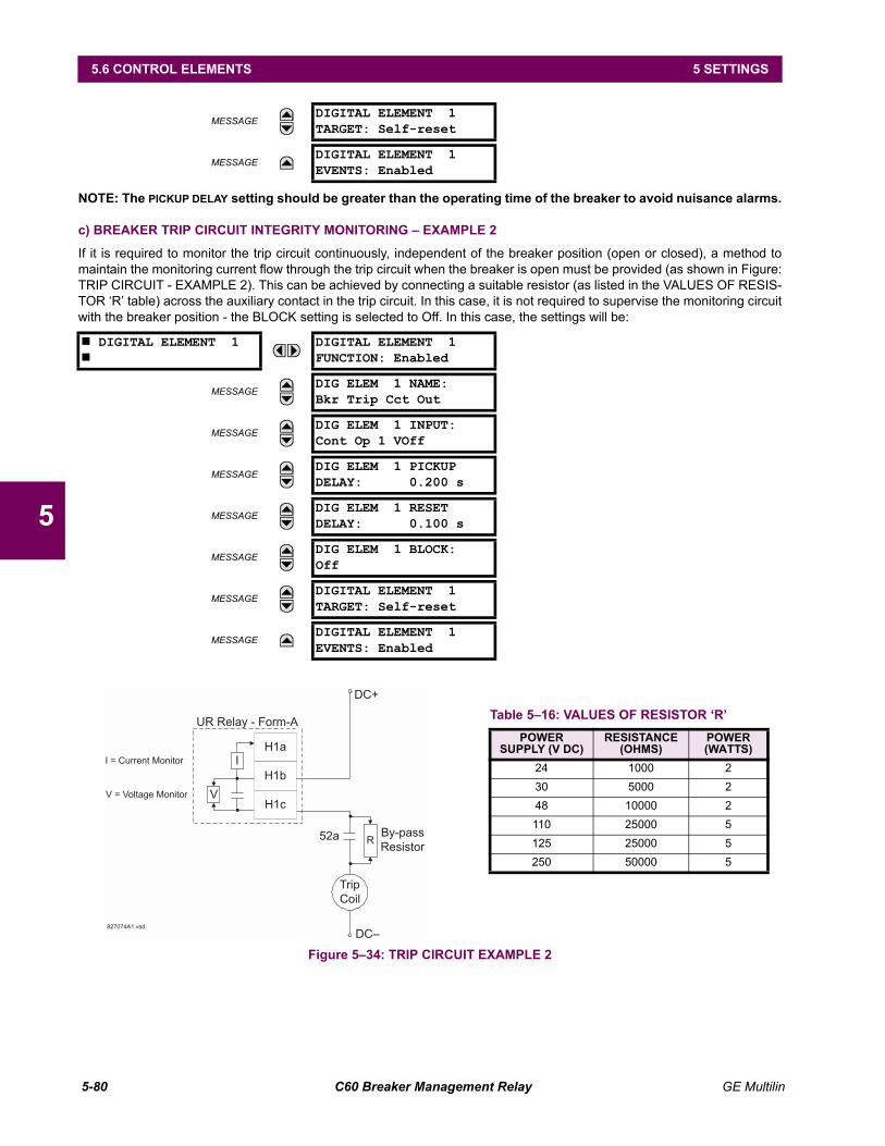
5-80 C60 Breaker Management Relay GE Multilin
5.6 CONTROL ELEMENTS 5 SETTINGS
5
NOTE: The PICKUP DELAY setting should be greater than the operating time of the breaker to avoid nuisance alarms.
c) BREAKER TRIP CIRCUIT INTEGRITY MONITORING EXAMPLE 2
If it is required to monitor the trip circuit continuously, independent of the breaker position (open or closed), a method tomaintain the monitoring current flow through the trip circuit when the breaker is open must be provided (as shown in Figure:TRIP CIRCUIT - EXAMPLE 2). This can be achieved by connecting a suitable resistor (as listed in the VALUES OF RESIS-TOR R table) across the auxiliary contact in the trip circuit. In this case, it is not required to supervise the monitoring circuitwith the breaker position - the BLOCK setting is selected to Off. In this case, the settings will be:
Figure 534: TRIP CIRCUIT EXAMPLE 2
MESSAGEDIGITAL ELEMENT 1TARGET: Self-reset
MESSAGEDIGITAL ELEMENT 1EVENTS: Enabled
# DIGITAL ELEMENT 1#
DIGITAL ELEMENT 1FUNCTION: Enabled
MESSAGEDIG ELEM 1 NAME:Bkr Trip Cct Out
MESSAGEDIG ELEM 1 INPUT:Cont Op 1 VOff
MESSAGEDIG ELEM 1 PICKUPDELAY: 0.200 s
MESSAGEDIG ELEM 1 RESETDELAY: 0.100 s
MESSAGEDIG ELEM 1 BLOCK:Off
MESSAGEDIGITAL ELEMENT 1TARGET: Self-reset
MESSAGEDIGITAL ELEMENT 1EVENTS: Enabled
Trip
Coil
52a
V
I
H1a
H1b
H1c
UR Relay - Form-A
V = Voltage Monitor
I = Current Monitor
DC+
DC–827074A1.vsd
RBy-pass
Resistor
Table 516: VALUES OF RESISTOR RPOWER
SUPPLY (V DC)RESISTANCE
(OHMS)POWER(WATTS)
24 1000 230 5000 248 10000 2110 25000 5125 25000 5250 50000 5
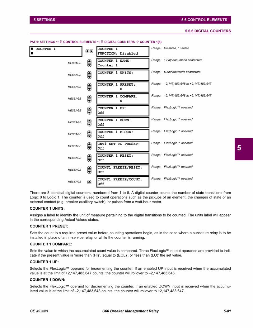
GE Multilin C60 Breaker Management Relay 5-81
5 SETTINGS 5.6 CONTROL ELEMENTS
5
5.6.6 DIGITAL COUNTERS
PATH: SETTINGS !" CONTROL ELEMENTS !" DIGITAL COUNTERS ! COUNTER 1(8)
There are 8 identical digital counters, numbered from 1 to 8. A digital counter counts the number of state transitions fromLogic 0 to Logic 1. The counter is used to count operations such as the pickups of an element, the changes of state of anexternal contact (e.g. breaker auxiliary switch), or pulses from a watt-hour meter.
COUNTER 1 UNITS:
Assigns a label to identify the unit of measure pertaining to the digital transitions to be counted. The units label will appearin the corresponding Actual Values status.
COUNTER 1 PRESET:
Sets the count to a required preset value before counting operations begin, as in the case where a substitute relay is to beinstalled in place of an in-service relay, or while the counter is running.
COUNTER 1 COMPARE:
Sets the value to which the accumulated count value is compared. Three FlexLogic output operands are provided to indi-cate if the present value is more than (HI), equal to (EQL), or less than (LO) the set value.
COUNTER 1 UP:
Selects the FlexLogic operand for incrementing the counter. If an enabled UP input is received when the accumulatedvalue is at the limit of +2,147,483,647 counts, the counter will rollover to 2,147,483,648.
COUNTER 1 DOWN:
Selects the FlexLogic operand for decrementing the counter. If an enabled DOWN input is received when the accumu-lated value is at the limit of 2,147,483,648 counts, the counter will rollover to +2,147,483,647.
# COUNTER 1#
COUNTER 1FUNCTION: Disabled
Range: Disabled, Enabled
MESSAGECOUNTER 1 NAME:Counter 1
Range: 12 alphanumeric characters
MESSAGECOUNTER 1 UNITS: Range: 6 alphanumeric characters
MESSAGECOUNTER 1 PRESET:
0Range: 2,147,483,648 to +2,147,483,647
MESSAGECOUNTER 1 COMPARE:
0Range: 2,147,483,648 to +2,147,483,647
MESSAGECOUNTER 1 UP:Off
Range: FlexLogic operand
MESSAGECOUNTER 1 DOWN:Off
Range: FlexLogic operand
MESSAGECOUNTER 1 BLOCK:Off
Range: FlexLogic operand
MESSAGECNT1 SET TO PRESET:Off
Range: FlexLogic operand
MESSAGECOUNTER 1 RESET:Off
Range: FlexLogic operand
MESSAGECOUNT1 FREEZE/RESET:Off
Range: FlexLogic operand
MESSAGECOUNT1 FREEZE/COUNT:Off
Range: FlexLogic operand

5-82 C60 Breaker Management Relay GE Multilin
5.6 CONTROL ELEMENTS 5 SETTINGS
5
COUNTER 1 BLOCK:
Selects the FlexLogic operand for blocking the counting operation. All counter operands are blocked.
CNT1 SET TO PRESET:
Selects the FlexLogic operand used to set the count to the preset value. The counter will be set to the preset value in thefollowing situations:
1. When the counter is enabled and the CNT1 SET TO PRESET operand has the value 1 (when the counter is enabled andCNT1 SET TO PRESET is 0, the counter will be set to 0.)
2. When the counter is running and the CNT1 SET TO PRESET operand changes the state from 0 to 1 (CNT1 SET TO PRESETchanging from 1 to 0 while the counter is running has no effect on the count).
3. When a reset or reset/freeze command is sent to the counter and the CNT1 SET TO PRESET operand has the value 1(when a reset or reset/freeze command is sent to the counter and the CNT1 SET TO PRESET operand has the value 0,the counter will be set to 0).
COUNTER 1 RESET:
Selects the FlexLogic operand for setting the count to either 0 or the preset value depending on the state of the CNT1SET TO PRESET operand.
COUNTER 1 FREEZE/RESET:
Selects the FlexLogic operand for capturing (freezing) the accumulated count value into a separate register with the dateand time of the operation, and resetting the count to 0.
COUNTER 1 FREEZE/COUNT:
Selects the FlexLogic operand for capturing (freezing) the accumulated count value into a separate register with the dateand time of the operation, and continuing counting. The present accumulated value and captured frozen value with theassociated date/time stamp are available as actual values. If control power is interrupted, the accumulated and frozen val-ues are saved into non-volatile memory during the power down operation.
Figure 535: DIGITAL COUNTER SCHEME LOGIC
827065A1.VSD
FLEXLOGICOPERANDSCOUNTER 1 HI
COUNTER 1 EQL
COUNTER 1 LO
SETTING
COUNTER 1 FUNCTION:
Disabled = 0
Enabled = 1
COUNTER 1 BLOCK:
COUNTER 1 UP:
COUNTER 1 DOWN:
COUNTER 1 RESET:
COUNT1 FREEZE/RESET:
COUNT1 FREEZE/COUNT:
Off = 0
COUNTER 1 UNITS:COUNTER 1 PRESET:
CALCULATEVALUE
RUN
SET TO PRESET VALUE
STORE DATE & TIME
COUNTER 1 NAME:
COUNTER 1 COMPARE:
Count more than Comp.
Count equal to Comp.
Count less than Comp.
COUNTER 1 FROZEN:
Date & Time
CNT 1 SET TO PRESET:
SET TO ZERO
SETTING
SETTING
SETTING
SETTING
SETTING
SETTING
SETTING
SETTINGS
Off = 0
Off = 0
Off = 0
Off = 0
Off = 0
Off = 0
ACTUAL VALUES
COUNTER 1 ACCUM:
ACTUAL VALUE
SETTING
AND
OR
OR
AND
AND
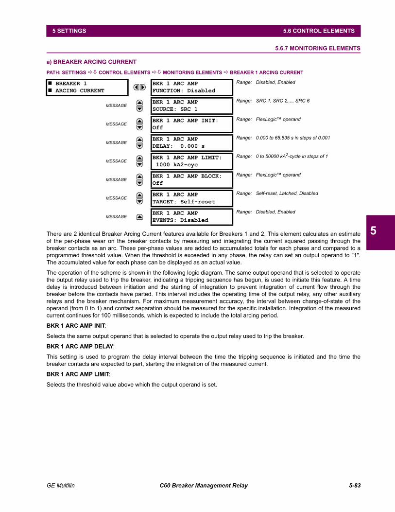
GE Multilin C60 Breaker Management Relay 5-83
5 SETTINGS 5.6 CONTROL ELEMENTS
5
5.6.7 MONITORING ELEMENTS
a) BREAKER ARCING CURRENT
PATH: SETTINGS !" CONTROL ELEMENTS !" MONITORING ELEMENTS ! BREAKER 1 ARCING CURRENT
There are 2 identical Breaker Arcing Current features available for Breakers 1 and 2. This element calculates an estimateof the per-phase wear on the breaker contacts by measuring and integrating the current squared passing through thebreaker contacts as an arc. These per-phase values are added to accumulated totals for each phase and compared to aprogrammed threshold value. When the threshold is exceeded in any phase, the relay can set an output operand to "1".The accumulated value for each phase can be displayed as an actual value.
The operation of the scheme is shown in the following logic diagram. The same output operand that is selected to operatethe output relay used to trip the breaker, indicating a tripping sequence has begun, is used to initiate this feature. A timedelay is introduced between initiation and the starting of integration to prevent integration of current flow through thebreaker before the contacts have parted. This interval includes the operating time of the output relay, any other auxiliaryrelays and the breaker mechanism. For maximum measurement accuracy, the interval between change-of-state of theoperand (from 0 to 1) and contact separation should be measured for the specific installation. Integration of the measuredcurrent continues for 100 milliseconds, which is expected to include the total arcing period.
BKR 1 ARC AMP INIT:
Selects the same output operand that is selected to operate the output relay used to trip the breaker.
BKR 1 ARC AMP DELAY:
This setting is used to program the delay interval between the time the tripping sequence is initiated and the time thebreaker contacts are expected to part, starting the integration of the measured current.
BKR 1 ARC AMP LIMIT:
Selects the threshold value above which the output operand is set.
# BREAKER 1# ARCING CURRENT
BKR 1 ARC AMPFUNCTION: Disabled
Range: Disabled, Enabled
MESSAGEBKR 1 ARC AMPSOURCE: SRC 1
Range: SRC 1, SRC 2,..., SRC 6
MESSAGEBKR 1 ARC AMP INIT:Off
Range: FlexLogic operand
MESSAGEBKR 1 ARC AMPDELAY: 0.000 s
Range: 0.000 to 65.535 s in steps of 0.001
MESSAGEBKR 1 ARC AMP LIMIT:1000 kA2-cyc
Range: 0 to 50000 kA2-cycle in steps of 1
MESSAGEBKR 1 ARC AMP BLOCK:Off
Range: FlexLogic operand
MESSAGEBKR 1 ARC AMPTARGET: Self-reset
Range: Self-reset, Latched, Disabled
MESSAGEBKR 1 ARC AMPEVENTS: Disabled
Range: Disabled, Enabled
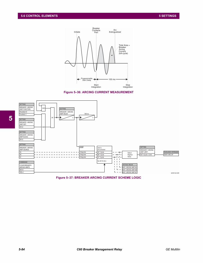
5-84 C60 Breaker Management Relay GE Multilin
5.6 CONTROL ELEMENTS 5 SETTINGS
5
Figure 536: ARCING CURRENT MEASUREMENT
Figure 537: BREAKER ARCING CURRENT SCHEME LOGIC
Initiate
BreakerContacts
PartArc
Extinguished
100 msProgrammableStart Delay
StartIntegration
StopIntegration
Total Area =BreakerArcingCurrent(kA·cycle)
SETTING
SETTING
SETTING
SETTING
COMMAND
ACTUAL VALUE
FLEXLOGIC OPERAND
SETTING
BREAKER 1 ARCINGAMP FUNCTION:
BREAKER 1 ARCINGAMP BLOCK:
BREAKER 1 ARCINGAMP INIT:
BREAKER 1 ARCINGAMP LIMIT:
CLEAR BREAKER 1ARCING AMPS: BKR 1 ARCING AMP A
BKR 1 ARCING AMP B
BKR 1 ARCING AMP C
BKR1 ARC OP
BREAKER 1 ARCINGAMP SOURCE:
IA
IB
IC
Off=0
Off=0
NO=0
YES=1
Enabled=1
Disabled=0
AND
AND
OR
827071A2.CDR
KA Cycle Limit2
*
SETTING
BREAKER 1 ARCINGAMP DELAY: 100 ms
0 0
Set All To Zero
Add toAccumulator
IntegrateSelectHighestValue
Integrate
Integrate
RUN
IB -Cycle
IA -Cycle
IC -Cycle
2
2
2

GE Multilin C60 Breaker Management Relay 5-85
5 SETTINGS 5.7 INPUTS / OUTPUTS
5
5.7 INPUTS / OUTPUTS 5.7.1 CONTACT INPUTS
PATH: SETTINGS !" INPUTS/OUTPUTS ! CONTACT INPUTS
The contact inputs menu contains configuration settings for each contact input as well as voltage thresholds for each groupof four contact inputs. Upon startup, the relay processor determines (from an assessment of the installed modules) whichcontact inputs are available and then display settings for only those inputs.
An alphanumeric ID may be assigned to a contact input for diagnostic, setting, and event recording purposes. The "ContactIp X On" (Logic 1) FlexLogic operand corresponds to contact input "X" being closed, while "Contact Input X Off" corre-sponds to contact input "X" being open. The CONTACT INPUT DEBNCE TIME defines the time required for the contact to over-come contact bouncing conditions. As this time differs for different contact types and manufacturers, set it as a maximumcontact debounce time (per manufacturer specifications) plus some margin to ensure proper operation. If CONTACT INPUTEVENTS is set to "Enabled", every change in the contact input state will trigger an event.
A raw status is scanned for all Contact Inputs synchronously at the constant rate of 0.5 ms as shown in the figure below.The DC input voltage is compared to a user-settable threshold. A new contact input state must be maintained for a user-settable debounce time in order for the C60 to validate the new contact state. In the figure below, the debounce time is setat 2.5 ms; thus the 6th sample in a row validates the change of state (mark no.1 in the diagram). Once validated (de-bounced), the contact input asserts a corresponding FlexLogic operand and logs an event as per user setting.
A time stamp of the first sample in the sequence that validates the new state is used when logging the change of the con-tact input into the Event Recorder (mark no. 2 in the diagram).
Protection and control elements, as well as FlexLogic equations and timers, are executed eight times in a power systemcycle. The protection pass duration is controlled by the frequency tracking mechanism. The FlexLogic operand reflectingthe debounced state of the contact is updated at the protection pass following the validation (marks no. 3 and 4 on the fig-ure below). The update is performed at the beginning of the protection pass so all protection and control functions, as wellas FlexLogic equations, are fed with the updated states of the contact inputs.
# CONTACT INPUTS#
# CONTACT INPUT H5a#
MESSAGECONTACT INPUT H5a ID:Cont Ip 1
Range: up to 12 alphanumeric characters
MESSAGECONTACT INPUT H5aDEBNCE TIME: 2.0 ms
Range: 0.0 to 16.0 ms in steps of 0.5
MESSAGECONTACT INPUT H5aEVENTS: Disabled
Range: Disabled, Enabled
↓
# CONTACT INPUT xxx#
# CONTACT INPUT# THRESHOLDS
MESSAGEIps H5a,H5c,H6a,H6cTHRESHOLD: 33 Vdc
Range: 17, 33, 84, 166 Vdc
MESSAGEIps H7a,H7c,H8a,H8cTHRESHOLD: 33 Vdc
Range: 17, 33, 84, 166 Vdc
↓
MESSAGEIps xxx,xxx,xxx,xxxTHRESHOLD: 33 Vdc
Range: 17, 33, 84, 166 Vdc

5-86 C60 Breaker Management Relay GE Multilin
5.7 INPUTS / OUTPUTS 5 SETTINGS
5
The FlexLogic operand response time to the contact input change is equal to the debounce time setting plus up to oneprotection pass (variable and depending on system frequency if frequency tracking enabled). If the change of state occursjust after a protection pass, the recognition is delayed until the subsequent protection pass; that is, by the entire duration ofthe protection pass. If the change occurs just prior to a protection pass, the state is recognized immediately. Statistically adelay of half the protection pass is expected. Owing to the 0.5 ms scan rate, the time resolution for the input contact isbelow 1msec.
For example, 8 protection passes per cycle on a 60 Hz system correspond to a protection pass every 2.1 ms. With a con-tact debounce time setting of 3.0 ms, the FlexLogic operand-assert time limits are: 3.0 + 0.0 = 3.0 ms and 3.0 + 2.1 = 5.1ms. These time limits depend on how soon the protection pass runs after the debouncing time.
Regardless of the contact debounce time setting, the contact input event is time-stamped with a 1 µs accuracy using thetime of the first scan corresponding to the new state (mark no. 2 below). Therefore, the time stamp reflects a change in theDC voltage across the contact input terminals that was not accidental as it was subsequently validated using the debouncetimer. Keep in mind that the associated FlexLogic operand is asserted/de-asserted later, after validating the change.
The debounce algorithm is symmetrical: the same procedure and debounce time are used to filter the LOW-HIGH (marksno.1, 2, 3, and 4 in the figure below) and HIGH-LOW (marks no.5, 6, 7, and 8 below) transitions.
Figure 538: INPUT CONTACT DEBOUNCING MECHANISM AND TIME-STAMPING SAMPLE TIMING
Contact inputs are isolated in groups of four to allow connection of wet contacts from different voltage sources for eachgroup. The CONTACT INPUT THRESHOLDS determine the minimum voltage required to detect a closed contact input. Thisvalue should be selected according to the following criteria: 17 for 24 V sources, 33 for 48 V sources, 84 for 110 to 125 Vsources and 166 for 250 V sources.
For example, to use contact input H5a as a status input from the breaker 52b contact to seal-in the trip relay and record it inthe Event Records menu, make the following settings changes:
CONTACT INPUT H5A ID: "Breaker Closed (52b)"CONTACT INPUT H5A EVENTS: "Enabled"
Note that the 52b contact is closed when the breaker is open and open when the breaker is closed.
842709A1.cdr
DEBOUNCE TIME
(user setting)
At this time, the
new (HIGH)
contact state is
validated
The FlexLogicTM
operand is going to
be asserted at this
protection pass
The FlexLogicTM operand
changes reflecting the
validated contact state
Time stamp of the first
scan corresponding to
the new validated state is
logged in the SOE record
2 1 3
4
DEBOUNCE TIME
(user setting)
At this time, the new
(LOW) contact state is
validated
The FlexLogicTM
operand is going to be
de-asserted at this
protection pass
The FlexLogicTM operand
changes reflecting the
validated contact state
5
7
8
Time stamp of the first
scan corresponding to the
new validated state is
logged in the SOE record
6
SCAN TIME
(0.5 msec)
PROTECTION PASS
(8 times a cycle controlled by the
frequency tracking mechanism)
RA
WC
ON
TA
CT
ST
AT
E
FLE
XLO
GIC
TM
OP
ER
AN
D
INP
UT
VO
LT
AG
E
USER-PROGRAMMABLE THRESHOLD
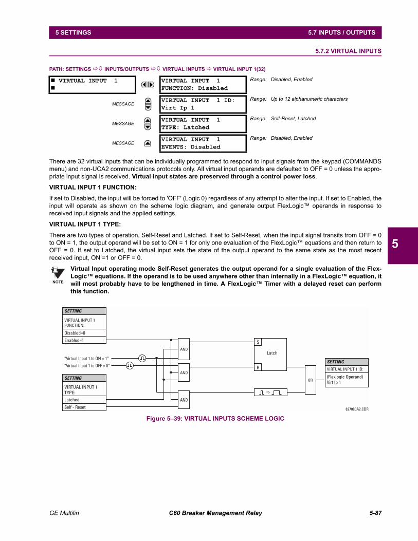
GE Multilin C60 Breaker Management Relay 5-87
5 SETTINGS 5.7 INPUTS / OUTPUTS
5
5.7.2 VIRTUAL INPUTS
PATH: SETTINGS !" INPUTS/OUTPUTS !" VIRTUAL INPUTS ! VIRTUAL INPUT 1(32)
There are 32 virtual inputs that can be individually programmed to respond to input signals from the keypad (COMMANDSmenu) and non-UCA2 communications protocols only. All virtual input operands are defaulted to OFF = 0 unless the appro-priate input signal is received. Virtual input states are preserved through a control power loss.
VIRTUAL INPUT 1 FUNCTION:
If set to Disabled, the input will be forced to 'OFF' (Logic 0) regardless of any attempt to alter the input. If set to Enabled, theinput will operate as shown on the scheme logic diagram, and generate output FlexLogic operands in response toreceived input signals and the applied settings.
VIRTUAL INPUT 1 TYPE:
There are two types of operation, Self-Reset and Latched. If set to Self-Reset, when the input signal transits from OFF = 0to ON = 1, the output operand will be set to ON = 1 for only one evaluation of the FlexLogic equations and then return toOFF = 0. If set to Latched, the virtual input sets the state of the output operand to the same state as the most recentreceived input, ON =1 or OFF = 0.
Virtual Input operating mode Self-Reset generates the output operand for a single evaluation of the Flex-Logic equations. If the operand is to be used anywhere other than internally in a FlexLogic equation, itwill most probably have to be lengthened in time. A FlexLogic Timer with a delayed reset can performthis function.
Figure 539: VIRTUAL INPUTS SCHEME LOGIC
# VIRTUAL INPUT 1#
VIRTUAL INPUT 1FUNCTION: Disabled
Range: Disabled, Enabled
MESSAGEVIRTUAL INPUT 1 ID:Virt Ip 1
Range: Up to 12 alphanumeric characters
MESSAGEVIRTUAL INPUT 1TYPE: Latched
Range: Self-Reset, Latched
MESSAGEVIRTUAL INPUT 1EVENTS: Disabled
Range: Disabled, Enabled
NOTE
VIRTUAL INPUT 1FUNCTION:
VIRTUAL INPUT 1 ID:“Virtual Input 1 to OFF = 0”
“Virtual Input 1 to ON = 1”
AND
AND
AND
OR
SETTING
SETTING
Enabled=1
Disabled=0
(Flexlogic Operand)Virt Ip 1
827080A2.CDR
SETTING
VIRTUAL INPUT 1TYPE:
Latched
Self - Reset
R
S
Latch
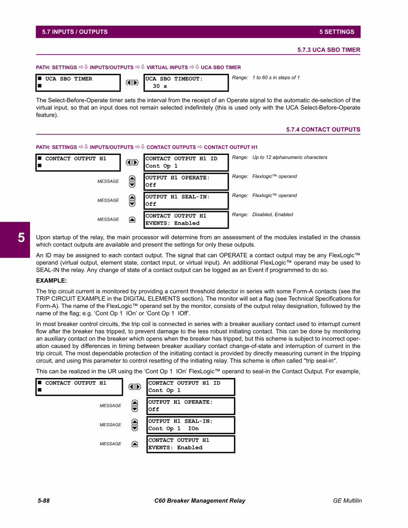
5-88 C60 Breaker Management Relay GE Multilin
5.7 INPUTS / OUTPUTS 5 SETTINGS
5
5.7.3 UCA SBO TIMER
PATH: SETTINGS !" INPUTS/OUTPUTS !" VIRTUAL INPUTS !" UCA SBO TIMER
The Select-Before-Operate timer sets the interval from the receipt of an Operate signal to the automatic de-selection of thevirtual input, so that an input does not remain selected indefinitely (this is used only with the UCA Select-Before-Operatefeature).
5.7.4 CONTACT OUTPUTS
PATH: SETTINGS !" INPUTS/OUTPUTS !" CONTACT OUTPUTS ! CONTACT OUTPUT H1
Upon startup of the relay, the main processor will determine from an assessment of the modules installed in the chassiswhich contact outputs are available and present the settings for only these outputs.
An ID may be assigned to each contact output. The signal that can OPERATE a contact output may be any FlexLogicoperand (virtual output, element state, contact input, or virtual input). An additional FlexLogic operand may be used toSEAL-IN the relay. Any change of state of a contact output can be logged as an Event if programmed to do so.
EXAMPLE:
The trip circuit current is monitored by providing a current threshold detector in series with some Form-A contacts (see theTRIP CIRCUIT EXAMPLE in the DIGITAL ELEMENTS section). The monitor will set a flag (see Technical Specifications forForm-A). The name of the FlexLogic operand set by the monitor, consists of the output relay designation, followed by thename of the flag; e.g. Cont Op 1 IOn or Cont Op 1 IOff.
In most breaker control circuits, the trip coil is connected in series with a breaker auxiliary contact used to interrupt currentflow after the breaker has tripped, to prevent damage to the less robust initiating contact. This can be done by monitoringan auxiliary contact on the breaker which opens when the breaker has tripped, but this scheme is subject to incorrect oper-ation caused by differences in timing between breaker auxiliary contact change-of-state and interruption of current in thetrip circuit. The most dependable protection of the initiating contact is provided by directly measuring current in the trippingcircuit, and using this parameter to control resetting of the initiating relay. This scheme is often called "trip seal-in".
This can be realized in the UR using the Cont Op 1 IOn FlexLogic operand to seal-in the Contact Output. For example,
# UCA SBO TIMER#
UCA SBO TIMEOUT:30 s
Range: 1 to 60 s in steps of 1
# CONTACT OUTPUT H1#
CONTACT OUTPUT H1 IDCont Op 1
Range: Up to 12 alphanumeric characters
MESSAGEOUTPUT H1 OPERATE:Off
Range: Flexlogic operand
MESSAGEOUTPUT H1 SEAL-IN:Off
Range: Flexlogic operand
MESSAGECONTACT OUTPUT H1EVENTS: Enabled
Range: Disabled, Enabled
# CONTACT OUTPUT H1#
CONTACT OUTPUT H1 IDCont Op 1
MESSAGEOUTPUT H1 OPERATE:Off
MESSAGEOUTPUT H1 SEAL-IN:Cont Op 1 IOn
MESSAGECONTACT OUTPUT H1EVENTS: Enabled
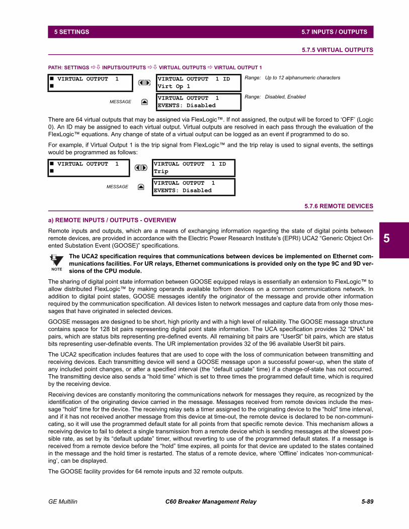
GE Multilin C60 Breaker Management Relay 5-89
5 SETTINGS 5.7 INPUTS / OUTPUTS
5
5.7.5 VIRTUAL OUTPUTS
PATH: SETTINGS !" INPUTS/OUTPUTS !" VIRTUAL OUTPUTS ! VIRTUAL OUTPUT 1
There are 64 virtual outputs that may be assigned via FlexLogic. If not assigned, the output will be forced to OFF (Logic0). An ID may be assigned to each virtual output. Virtual outputs are resolved in each pass through the evaluation of theFlexLogic equations. Any change of state of a virtual output can be logged as an event if programmed to do so.
For example, if Virtual Output 1 is the trip signal from FlexLogic and the trip relay is used to signal events, the settingswould be programmed as follows:
5.7.6 REMOTE DEVICES
a) REMOTE INPUTS / OUTPUTS - OVERVIEW
Remote inputs and outputs, which are a means of exchanging information regarding the state of digital points betweenremote devices, are provided in accordance with the Electric Power Research Institutes (EPRI) UCA2 Generic Object Ori-ented Substation Event (GOOSE) specifications.
The UCA2 specification requires that communications between devices be implemented on Ethernet com-munications facilities. For UR relays, Ethernet communications is provided only on the type 9C and 9D ver-sions of the CPU module.
The sharing of digital point state information between GOOSE equipped relays is essentially an extension to FlexLogic toallow distributed FlexLogic by making operands available to/from devices on a common communications network. Inaddition to digital point states, GOOSE messages identify the originator of the message and provide other informationrequired by the communication specification. All devices listen to network messages and capture data from only those mes-sages that have originated in selected devices.
GOOSE messages are designed to be short, high priority and with a high level of reliability. The GOOSE message structurecontains space for 128 bit pairs representing digital point state information. The UCA specification provides 32 DNA bitpairs, which are status bits representing pre-defined events. All remaining bit pairs are UserSt bit pairs, which are statusbits representing user-definable events. The UR implementation provides 32 of the 96 available UserSt bit pairs.
The UCA2 specification includes features that are used to cope with the loss of communication between transmitting andreceiving devices. Each transmitting device will send a GOOSE message upon a successful power-up, when the state ofany included point changes, or after a specified interval (the default update time) if a change-of-state has not occurred.The transmitting device also sends a hold time which is set to three times the programmed default time, which is requiredby the receiving device.
Receiving devices are constantly monitoring the communications network for messages they require, as recognized by theidentification of the originating device carried in the message. Messages received from remote devices include the mes-sage hold time for the device. The receiving relay sets a timer assigned to the originating device to the hold time interval,and if it has not received another message from this device at time-out, the remote device is declared to be non-communi-cating, so it will use the programmed default state for all points from that specific remote device. This mechanism allows areceiving device to fail to detect a single transmission from a remote device which is sending messages at the slowest pos-sible rate, as set by its default update timer, without reverting to use of the programmed default states. If a message isreceived from a remote device before the hold time expires, all points for that device are updated to the states containedin the message and the hold timer is restarted. The status of a remote device, where Offline indicates non-communicat-ing, can be displayed.
The GOOSE facility provides for 64 remote inputs and 32 remote outputs.
# VIRTUAL OUTPUT 1#
VIRTUAL OUTPUT 1 IDVirt Op 1
Range: Up to 12 alphanumeric characters
MESSAGEVIRTUAL OUTPUT 1EVENTS: Disabled
Range: Disabled, Enabled
# VIRTUAL OUTPUT 1#
VIRTUAL OUTPUT 1 IDTrip
MESSAGEVIRTUAL OUTPUT 1EVENTS: Disabled
NOTE
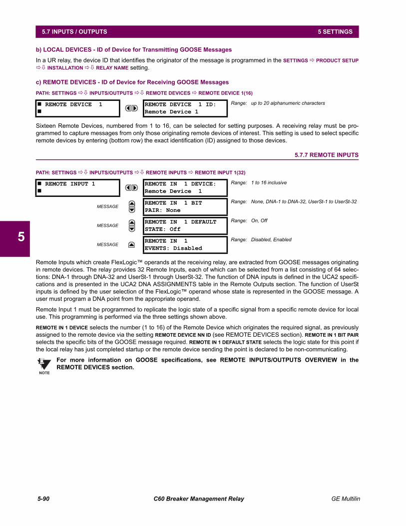
5-90 C60 Breaker Management Relay GE Multilin
5.7 INPUTS / OUTPUTS 5 SETTINGS
5
b) LOCAL DEVICES - ID of Device for Transmitting GOOSE Messages
In a UR relay, the device ID that identifies the originator of the message is programmed in the SETTINGS ! PRODUCT SETUP!" INSTALLATION !" RELAY NAME setting.
c) REMOTE DEVICES - ID of Device for Receiving GOOSE Messages
PATH: SETTINGS !" INPUTS/OUTPUTS !" REMOTE DEVICES ! REMOTE DEVICE 1(16)
Sixteen Remote Devices, numbered from 1 to 16, can be selected for setting purposes. A receiving relay must be pro-grammed to capture messages from only those originating remote devices of interest. This setting is used to select specificremote devices by entering (bottom row) the exact identification (ID) assigned to those devices.
5.7.7 REMOTE INPUTS
PATH: SETTINGS !" INPUTS/OUTPUTS !" REMOTE INPUTS ! REMOTE INPUT 1(32)
Remote Inputs which create FlexLogic operands at the receiving relay, are extracted from GOOSE messages originatingin remote devices. The relay provides 32 Remote Inputs, each of which can be selected from a list consisting of 64 selec-tions: DNA-1 through DNA-32 and UserSt-1 through UserSt-32. The function of DNA inputs is defined in the UCA2 specifi-cations and is presented in the UCA2 DNA ASSIGNMENTS table in the Remote Outputs section. The function of UserStinputs is defined by the user selection of the FlexLogic operand whose state is represented in the GOOSE message. Auser must program a DNA point from the appropriate operand.
Remote Input 1 must be programmed to replicate the logic state of a specific signal from a specific remote device for localuse. This programming is performed via the three settings shown above.
REMOTE IN 1 DEVICE selects the number (1 to 16) of the Remote Device which originates the required signal, as previouslyassigned to the remote device via the setting REMOTE DEVICE NN ID (see REMOTE DEVICES section). REMOTE IN 1 BIT PAIRselects the specific bits of the GOOSE message required. REMOTE IN 1 DEFAULT STATE selects the logic state for this point ifthe local relay has just completed startup or the remote device sending the point is declared to be non-communicating.
For more information on GOOSE specifications, see REMOTE INPUTS/OUTPUTS OVERVIEW in theREMOTE DEVICES section.
# REMOTE DEVICE 1#
REMOTE DEVICE 1 ID:Remote Device 1
Range: up to 20 alphanumeric characters
# REMOTE INPUT 1#
REMOTE IN 1 DEVICE:Remote Device 1
Range: 1 to 16 inclusive
MESSAGEREMOTE IN 1 BITPAIR: None
Range: None, DNA-1 to DNA-32, UserSt-1 to UserSt-32
MESSAGEREMOTE IN 1 DEFAULTSTATE: Off
Range: On, Off
MESSAGEREMOTE IN 1EVENTS: Disabled
Range: Disabled, Enabled
NOTE
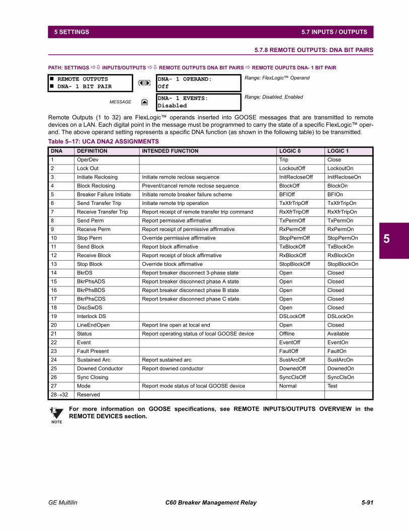
GE Multilin C60 Breaker Management Relay 5-91
5 SETTINGS 5.7 INPUTS / OUTPUTS
5
5.7.8 REMOTE OUTPUTS: DNA BIT PAIRS
PATH: SETTINGS !" INPUTS/OUTPUTS !" REMOTE OUTPUTS DNA BIT PAIRS ! REMOTE OUPUTS DNA- 1 BIT PAIR
Remote Outputs (1 to 32) are FlexLogic operands inserted into GOOSE messages that are transmitted to remotedevices on a LAN. Each digital point in the message must be programmed to carry the state of a specific FlexLogic oper-and. The above operand setting represents a specific DNA function (as shown in the following table) to be transmitted.
For more information on GOOSE specifications, see REMOTE INPUTS/OUTPUTS OVERVIEW in theREMOTE DEVICES section.
# REMOTE OUTPUTS# DNA- 1 BIT PAIR
DNA- 1 OPERAND:Off
Range: FlexLogic Operand
MESSAGEDNA- 1 EVENTS:Disabled
Range: Disabled, Enabled
Table 517: UCA DNA2 ASSIGNMENTSDNA DEFINITION INTENDED FUNCTION LOGIC 0 LOGIC 11 OperDev Trip Close2 Lock Out LockoutOff LockoutOn3 Initiate Reclosing Initiate remote reclose sequence InitRecloseOff InitRecloseOn4 Block Reclosing Prevent/cancel remote reclose sequence BlockOff BlockOn5 Breaker Failure Initiate Initiate remote breaker failure scheme BFIOff BFIOn6 Send Transfer Trip Initiate remote trip operation TxXfrTripOff TxXfrTripOn7 Receive Transfer Trip Report receipt of remote transfer trip command RxXfrTripOff RxXfrTripOn8 Send Perm Report permissive affirmative TxPermOff TxPermOn9 Receive Perm Report receipt of permissive affirmative RxPermOff RxPermOn10 Stop Perm Override permissive affirmative StopPermOff StopPermOn11 Send Block Report block affirmative TxBlockOff TxBlockOn12 Receive Block Report receipt of block affirmative RxBlockOff RxBlockOn13 Stop Block Override block affirmative StopBlockOff StopBlockOn14 BkrDS Report breaker disconnect 3-phase state Open Closed15 BkrPhsADS Report breaker disconnect phase A state Open Closed16 BkrPhsBDS Report breaker disconnect phase B state Open Closed17 BkrPhsCDS Report breaker disconnect phase C state Open Closed18 DiscSwDS Open Closed19 Interlock DS DSLockOff DSLockOn20 LineEndOpen Report line open at local end Open Closed21 Status Report operating status of local GOOSE device Offline Available22 Event EventOff EventOn23 Fault Present FaultOff FaultOn24 Sustained Arc Report sustained arc SustArcOff SustArcOn25 Downed Conductor Report downed conductor DownedOff DownedOn26 Sync Closing SyncClsOff SyncClsOn27 Mode Report mode status of local GOOSE device Normal Test28→32 Reserved
NOTE
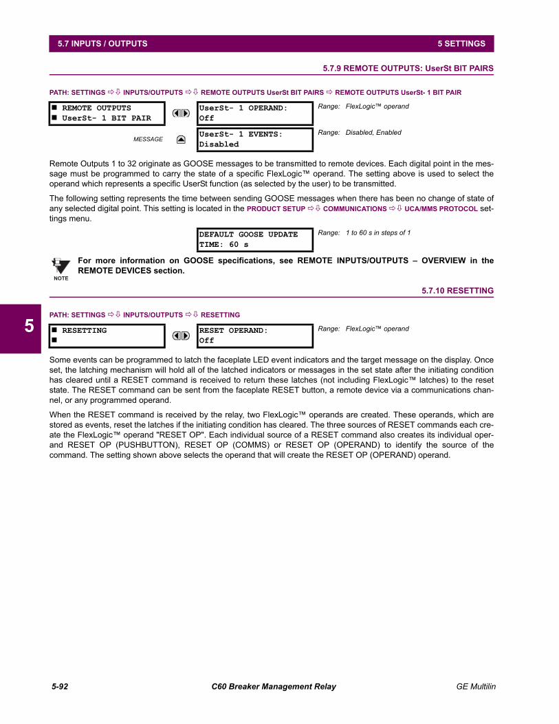
5-92 C60 Breaker Management Relay GE Multilin
5.7 INPUTS / OUTPUTS 5 SETTINGS
5
5.7.9 REMOTE OUTPUTS: UserSt BIT PAIRS
PATH: SETTINGS !" INPUTS/OUTPUTS !" REMOTE OUTPUTS UserSt BIT PAIRS ! REMOTE OUTPUTS UserSt- 1 BIT PAIR
Remote Outputs 1 to 32 originate as GOOSE messages to be transmitted to remote devices. Each digital point in the mes-sage must be programmed to carry the state of a specific FlexLogic operand. The setting above is used to select theoperand which represents a specific UserSt function (as selected by the user) to be transmitted.
The following setting represents the time between sending GOOSE messages when there has been no change of state ofany selected digital point. This setting is located in the PRODUCT SETUP !" COMMUNICATIONS !" UCA/MMS PROTOCOL set-tings menu.
For more information on GOOSE specifications, see REMOTE INPUTS/OUTPUTS OVERVIEW in theREMOTE DEVICES section.
5.7.10 RESETTING
PATH: SETTINGS !" INPUTS/OUTPUTS !" RESETTING
Some events can be programmed to latch the faceplate LED event indicators and the target message on the display. Onceset, the latching mechanism will hold all of the latched indicators or messages in the set state after the initiating conditionhas cleared until a RESET command is received to return these latches (not including FlexLogic latches) to the resetstate. The RESET command can be sent from the faceplate RESET button, a remote device via a communications chan-nel, or any programmed operand.
When the RESET command is received by the relay, two FlexLogic operands are created. These operands, which arestored as events, reset the latches if the initiating condition has cleared. The three sources of RESET commands each cre-ate the FlexLogic operand "RESET OP". Each individual source of a RESET command also creates its individual oper-and RESET OP (PUSHBUTTON), RESET OP (COMMS) or RESET OP (OPERAND) to identify the source of thecommand. The setting shown above selects the operand that will create the RESET OP (OPERAND) operand.
# REMOTE OUTPUTS# UserSt- 1 BIT PAIR
UserSt- 1 OPERAND:Off
Range: FlexLogic operand
MESSAGEUserSt- 1 EVENTS:Disabled
Range: Disabled, Enabled
DEFAULT GOOSE UPDATETIME: 60 s
Range: 1 to 60 s in steps of 1
# RESETTING#
RESET OPERAND:Off
Range: FlexLogic operand
NOTE
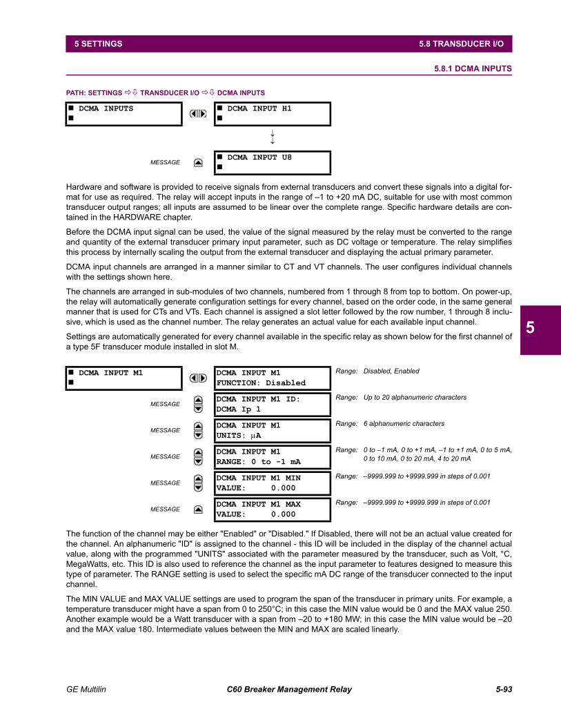
GE Multilin C60 Breaker Management Relay 5-93
5 SETTINGS 5.8 TRANSDUCER I/O
5
5.8 TRANSDUCER I/O 5.8.1 DCMA INPUTS
PATH: SETTINGS !" TRANSDUCER I/O !" DCMA INPUTS
Hardware and software is provided to receive signals from external transducers and convert these signals into a digital for-mat for use as required. The relay will accept inputs in the range of 1 to +20 mA DC, suitable for use with most commontransducer output ranges; all inputs are assumed to be linear over the complete range. Specific hardware details are con-tained in the HARDWARE chapter.
Before the DCMA input signal can be used, the value of the signal measured by the relay must be converted to the rangeand quantity of the external transducer primary input parameter, such as DC voltage or temperature. The relay simplifiesthis process by internally scaling the output from the external transducer and displaying the actual primary parameter.
DCMA input channels are arranged in a manner similar to CT and VT channels. The user configures individual channelswith the settings shown here.
The channels are arranged in sub-modules of two channels, numbered from 1 through 8 from top to bottom. On power-up,the relay will automatically generate configuration settings for every channel, based on the order code, in the same generalmanner that is used for CTs and VTs. Each channel is assigned a slot letter followed by the row number, 1 through 8 inclu-sive, which is used as the channel number. The relay generates an actual value for each available input channel.
Settings are automatically generated for every channel available in the specific relay as shown below for the first channel ofa type 5F transducer module installed in slot M.
The function of the channel may be either "Enabled" or "Disabled." If Disabled, there will not be an actual value created forthe channel. An alphanumeric "ID" is assigned to the channel - this ID will be included in the display of the channel actualvalue, along with the programmed "UNITS" associated with the parameter measured by the transducer, such as Volt, °C,MegaWatts, etc. This ID is also used to reference the channel as the input parameter to features designed to measure thistype of parameter. The RANGE setting is used to select the specific mA DC range of the transducer connected to the inputchannel.
The MIN VALUE and MAX VALUE settings are used to program the span of the transducer in primary units. For example, atemperature transducer might have a span from 0 to 250°C; in this case the MIN value would be 0 and the MAX value 250.Another example would be a Watt transducer with a span from 20 to +180 MW; in this case the MIN value would be 20and the MAX value 180. Intermediate values between the MIN and MAX are scaled linearly.
# DCMA INPUTS#
# DCMA INPUT H1#
↓↓
MESSAGE# DCMA INPUT U8#
# DCMA INPUT M1#
DCMA INPUT M1FUNCTION: Disabled
Range: Disabled, Enabled
MESSAGEDCMA INPUT M1 ID:DCMA Ip 1
Range: Up to 20 alphanumeric characters
MESSAGEDCMA INPUT M1UNITS: µA
Range: 6 alphanumeric characters
MESSAGEDCMA INPUT M1RANGE: 0 to -1 mA
Range: 0 to 1 mA, 0 to +1 mA, 1 to +1 mA, 0 to 5 mA,0 to 10 mA, 0 to 20 mA, 4 to 20 mA
MESSAGEDCMA INPUT M1 MINVALUE: 0.000
Range: 9999.999 to +9999.999 in steps of 0.001
MESSAGEDCMA INPUT M1 MAXVALUE: 0.000
Range: 9999.999 to +9999.999 in steps of 0.001
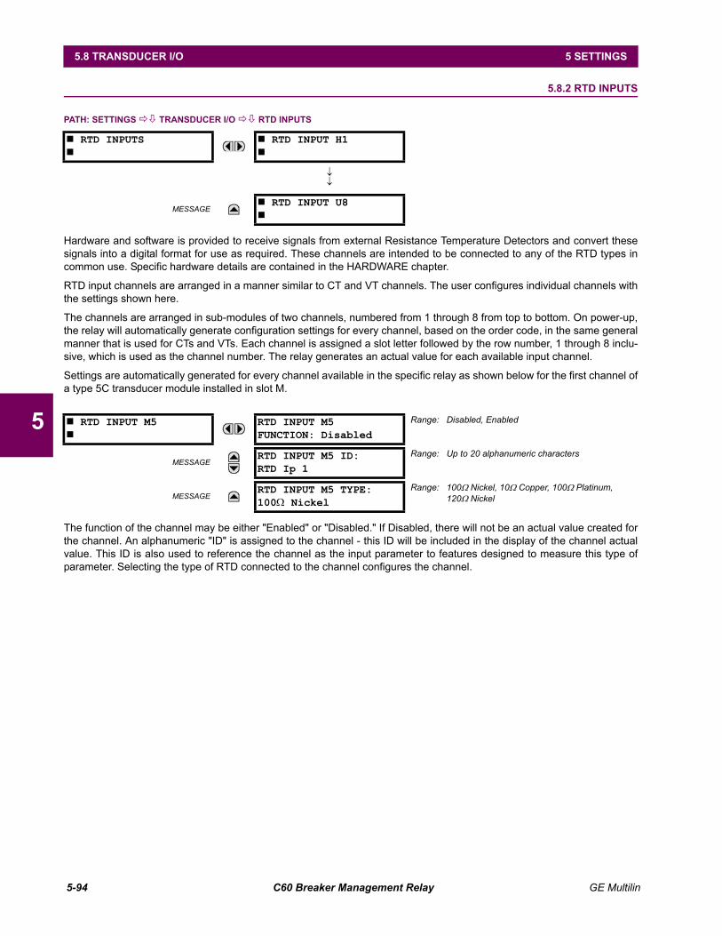
5-94 C60 Breaker Management Relay GE Multilin
5.8 TRANSDUCER I/O 5 SETTINGS
5
5.8.2 RTD INPUTS
PATH: SETTINGS !" TRANSDUCER I/O !" RTD INPUTS
Hardware and software is provided to receive signals from external Resistance Temperature Detectors and convert thesesignals into a digital format for use as required. These channels are intended to be connected to any of the RTD types incommon use. Specific hardware details are contained in the HARDWARE chapter.
RTD input channels are arranged in a manner similar to CT and VT channels. The user configures individual channels withthe settings shown here.
The channels are arranged in sub-modules of two channels, numbered from 1 through 8 from top to bottom. On power-up,the relay will automatically generate configuration settings for every channel, based on the order code, in the same generalmanner that is used for CTs and VTs. Each channel is assigned a slot letter followed by the row number, 1 through 8 inclu-sive, which is used as the channel number. The relay generates an actual value for each available input channel.
Settings are automatically generated for every channel available in the specific relay as shown below for the first channel ofa type 5C transducer module installed in slot M.
The function of the channel may be either "Enabled" or "Disabled." If Disabled, there will not be an actual value created forthe channel. An alphanumeric "ID" is assigned to the channel - this ID will be included in the display of the channel actualvalue. This ID is also used to reference the channel as the input parameter to features designed to measure this type ofparameter. Selecting the type of RTD connected to the channel configures the channel.
# RTD INPUTS#
# RTD INPUT H1#
↓↓
MESSAGE# RTD INPUT U8#
# RTD INPUT M5#
RTD INPUT M5FUNCTION: Disabled
Range: Disabled, Enabled
MESSAGERTD INPUT M5 ID:RTD Ip 1
Range: Up to 20 alphanumeric characters
MESSAGERTD INPUT M5 TYPE:100Ω Nickel
Range: 100Ω Nickel, 10Ω Copper, 100Ω Platinum, 120Ω Nickel
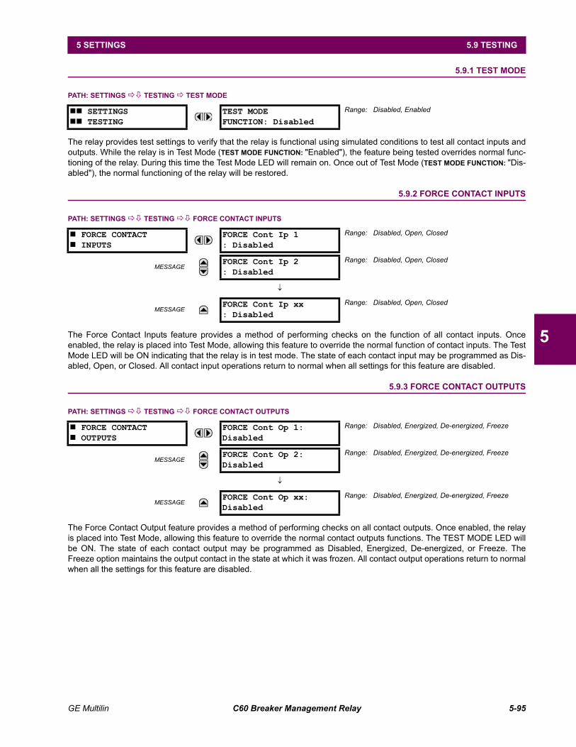
GE Multilin C60 Breaker Management Relay 5-95
5 SETTINGS 5.9 TESTING
5
5.9 TESTING 5.9.1 TEST MODE
PATH: SETTINGS !" TESTING ! TEST MODE
The relay provides test settings to verify that the relay is functional using simulated conditions to test all contact inputs andoutputs. While the relay is in Test Mode (TEST MODE FUNCTION: "Enabled"), the feature being tested overrides normal func-tioning of the relay. During this time the Test Mode LED will remain on. Once out of Test Mode (TEST MODE FUNCTION: "Dis-abled"), the normal functioning of the relay will be restored.
5.9.2 FORCE CONTACT INPUTS
PATH: SETTINGS !" TESTING !" FORCE CONTACT INPUTS
The Force Contact Inputs feature provides a method of performing checks on the function of all contact inputs. Onceenabled, the relay is placed into Test Mode, allowing this feature to override the normal function of contact inputs. The TestMode LED will be ON indicating that the relay is in test mode. The state of each contact input may be programmed as Dis-abled, Open, or Closed. All contact input operations return to normal when all settings for this feature are disabled.
5.9.3 FORCE CONTACT OUTPUTS
PATH: SETTINGS !" TESTING !" FORCE CONTACT OUTPUTS
The Force Contact Output feature provides a method of performing checks on all contact outputs. Once enabled, the relayis placed into Test Mode, allowing this feature to override the normal contact outputs functions. The TEST MODE LED willbe ON. The state of each contact output may be programmed as Disabled, Energized, De-energized, or Freeze. TheFreeze option maintains the output contact in the state at which it was frozen. All contact output operations return to normalwhen all the settings for this feature are disabled.
## SETTINGS## TESTING
TEST MODEFUNCTION: Disabled
Range: Disabled, Enabled
# FORCE CONTACT# INPUTS
FORCE Cont Ip 1: Disabled
Range: Disabled, Open, Closed
MESSAGEFORCE Cont Ip 2: Disabled
Range: Disabled, Open, Closed
↓
MESSAGEFORCE Cont Ip xx: Disabled
Range: Disabled, Open, Closed
# FORCE CONTACT# OUTPUTS
FORCE Cont Op 1:Disabled
Range: Disabled, Energized, De-energized, Freeze
MESSAGEFORCE Cont Op 2:Disabled
Range: Disabled, Energized, De-energized, Freeze
↓
MESSAGEFORCE Cont Op xx:Disabled
Range: Disabled, Energized, De-energized, Freeze

5-96 C60 Breaker Management Relay GE Multilin
5.9 TESTING 5 SETTINGS
5
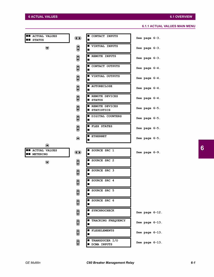
GE Multilin C60 Breaker Management Relay 6-1
6 ACTUAL VALUES 6.1 OVERVIEW
6
6 ACTUAL VALUES 6.1 OVERVIEW 6.1.1 ACTUAL VALUES MAIN MENU
## ACTUAL VALUES## STATUS
# CONTACT INPUTS#
See page 6-3.
# VIRTUAL INPUTS#
See page 6-3.
# REMOTE INPUTS#
See page 6-3.
# CONTACT OUTPUTS#
See page 6-4.
# VIRTUAL OUTPUTS#
See page 6-4.
# AUTORECLOSE#
See page 6-4.
# REMOTE DEVICES# STATUS
See page 6-4.
# REMOTE DEVICES# STATISTICS
See page 6-5.
# DIGITAL COUNTERS#
See page 6-5.
# FLEX STATES#
See page 6-5.
# ETHERNET#
See page 6-5.
## ACTUAL VALUES## METERING
# SOURCE SRC 1#
See page 6-9.
# SOURCE SRC 2#
# SOURCE SRC 3#
# SOURCE SRC 4#
# SOURCE SRC 5#
# SOURCE SRC 6#
# SYNCHROCHECK#
See page 6-12.
# TRACKING FREQUENCY#
See page 6-13.
# FLEXELEMENTS#
See page 6-13.
# TRANSDUCER I/O# DCMA INPUTS
See page 6-13.
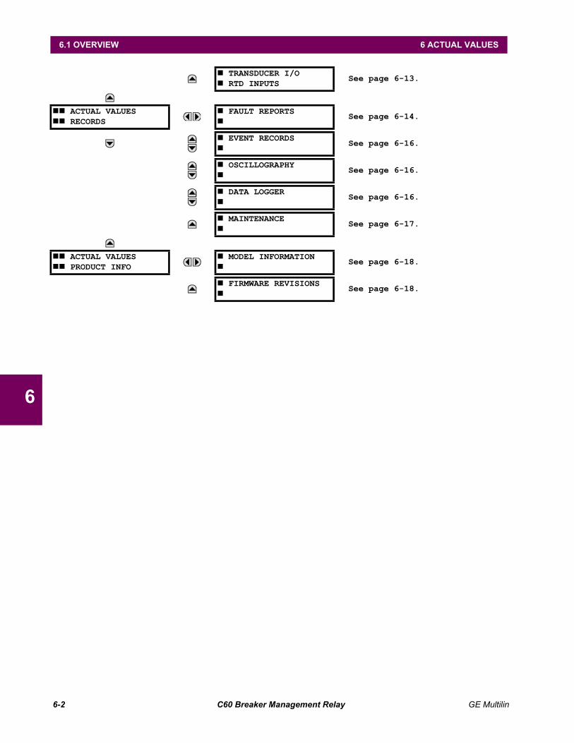
6-2 C60 Breaker Management Relay GE Multilin
6.1 OVERVIEW 6 ACTUAL VALUES
6
# TRANSDUCER I/O# RTD INPUTS
See page 6-13.
## ACTUAL VALUES## RECORDS
# FAULT REPORTS#
See page 6-14.
# EVENT RECORDS#
See page 6-16.
# OSCILLOGRAPHY#
See page 6-16.
# DATA LOGGER#
See page 6-16.
# MAINTENANCE#
See page 6-17.
## ACTUAL VALUES## PRODUCT INFO
# MODEL INFORMATION#
See page 6-18.
# FIRMWARE REVISIONS#
See page 6-18.
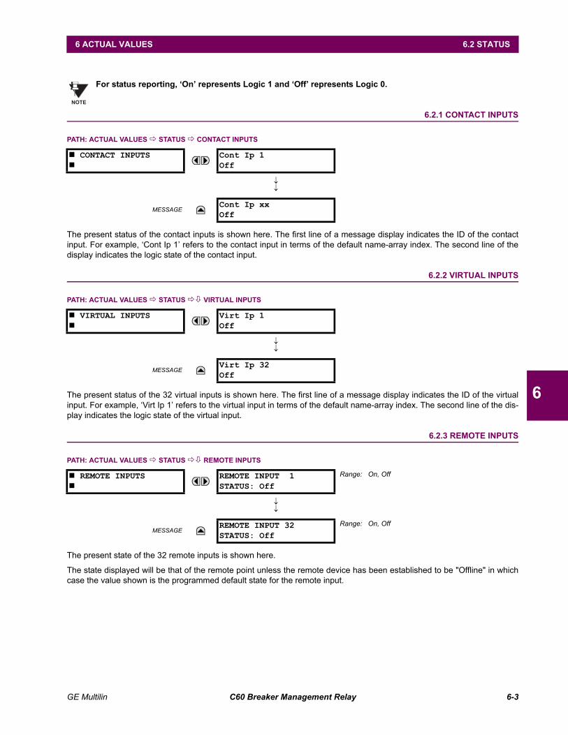
GE Multilin C60 Breaker Management Relay 6-3
6 ACTUAL VALUES 6.2 STATUS
6
6.2 STATUS
For status reporting, On represents Logic 1 and Off represents Logic 0.
6.2.1 CONTACT INPUTS
PATH: ACTUAL VALUES ! STATUS ! CONTACT INPUTS
The present status of the contact inputs is shown here. The first line of a message display indicates the ID of the contactinput. For example, Cont Ip 1 refers to the contact input in terms of the default name-array index. The second line of thedisplay indicates the logic state of the contact input.
6.2.2 VIRTUAL INPUTS
PATH: ACTUAL VALUES ! STATUS !" VIRTUAL INPUTS
The present status of the 32 virtual inputs is shown here. The first line of a message display indicates the ID of the virtualinput. For example, Virt Ip 1 refers to the virtual input in terms of the default name-array index. The second line of the dis-play indicates the logic state of the virtual input.
6.2.3 REMOTE INPUTS
PATH: ACTUAL VALUES ! STATUS !" REMOTE INPUTS
The present state of the 32 remote inputs is shown here.
The state displayed will be that of the remote point unless the remote device has been established to be "Offline" in whichcase the value shown is the programmed default state for the remote input.
# CONTACT INPUTS#
Cont Ip 1Off
↓↓
MESSAGECont Ip xxOff
# VIRTUAL INPUTS#
Virt Ip 1Off
↓↓
MESSAGEVirt Ip 32Off
# REMOTE INPUTS#
REMOTE INPUT 1STATUS: Off
Range: On, Off
↓↓
MESSAGEREMOTE INPUT 32STATUS: Off
Range: On, Off
NOTE
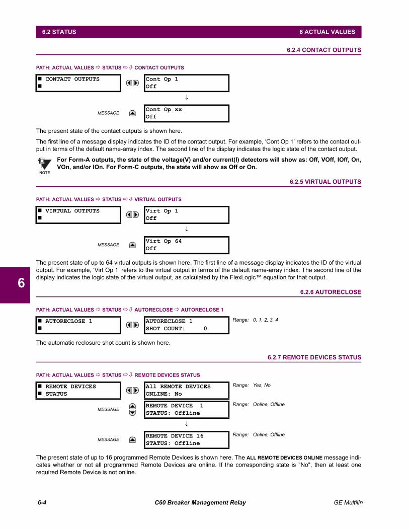
6-4 C60 Breaker Management Relay GE Multilin
6.2 STATUS 6 ACTUAL VALUES
6
6.2.4 CONTACT OUTPUTS
PATH: ACTUAL VALUES ! STATUS !" CONTACT OUTPUTS
The present state of the contact outputs is shown here.
The first line of a message display indicates the ID of the contact output. For example, Cont Op 1 refers to the contact out-put in terms of the default name-array index. The second line of the display indicates the logic state of the contact output.
For Form-A outputs, the state of the voltage(V) and/or current(I) detectors will show as: Off, VOff, IOff, On,VOn, and/or IOn. For Form-C outputs, the state will show as Off or On.
6.2.5 VIRTUAL OUTPUTS
PATH: ACTUAL VALUES ! STATUS !" VIRTUAL OUTPUTS
The present state of up to 64 virtual outputs is shown here. The first line of a message display indicates the ID of the virtualoutput. For example, Virt Op 1 refers to the virtual output in terms of the default name-array index. The second line of thedisplay indicates the logic state of the virtual output, as calculated by the FlexLogic equation for that output.
6.2.6 AUTORECLOSE
PATH: ACTUAL VALUES ! STATUS !" AUTORECLOSE ! AUTORECLOSE 1
The automatic reclosure shot count is shown here.
6.2.7 REMOTE DEVICES STATUS
PATH: ACTUAL VALUES ! STATUS !" REMOTE DEVICES STATUS
The present state of up to 16 programmed Remote Devices is shown here. The ALL REMOTE DEVICES ONLINE message indi-cates whether or not all programmed Remote Devices are online. If the corresponding state is "No", then at least onerequired Remote Device is not online.
# CONTACT OUTPUTS#
Cont Op 1Off
↓
MESSAGECont Op xxOff
# VIRTUAL OUTPUTS#
Virt Op 1Off
↓
MESSAGEVirt Op 64Off
# AUTORECLOSE 1#
AUTORECLOSE 1SHOT COUNT: 0
Range: 0, 1, 2, 3, 4
# REMOTE DEVICES# STATUS
All REMOTE DEVICESONLINE: No
Range: Yes, No
MESSAGEREMOTE DEVICE 1STATUS: Offline
Range: Online, Offline
↓
MESSAGEREMOTE DEVICE 16STATUS: Offline
Range: Online, Offline
NOTE

GE Multilin C60 Breaker Management Relay 6-5
6 ACTUAL VALUES 6.2 STATUS
6
6.2.8 REMOTE DEVICES STATISTICS
PATH: ACTUAL VALUES ! STATUS !" REMOTE DEVICES STATISTICS ! REMOTE DEVICE 1(16)
Statistical data (2 types) for up to 16 programmed Remote Devices is shown here.
The StNum number is obtained from the indicated Remote Device and is incremented whenever a change of state ofat least one DNA or UserSt bit occurs.
The SqNum number is obtained from the indicated Remote Device and is incremented whenever a GOOSE messageis sent. This number will rollover to zero when a count of 4,294,967,295 is incremented.
6.2.9 DIGITAL COUNTERS
PATH: ACTUAL VALUES ! DIGITAL COUNTERS !" DIGITAL COUNTERS ! DIGITAL COUNTERS Counter 1(8)
The present status of the 8 digital counters is shown here. The status of each counter, with the user-defined counter name,includes the accumulated and frozen counts (the count units label will also appear). Also included, is the date/time stampfor the frozen count. The Counter n MICROS value refers to the microsecond portion of the time stamp.
6.2.10 FLEX STATES
PATH: ACTUAL VALUES ! STATUS !" FLEX STATES
There are 256 FlexState bits available. The second line value indicates the state of the given FlexState bit.
6.2.11 ETHERNET
PATH: ACTUAL VALUES ! STATUS !" ETHERNET
# REMOTE DEVICE 1#
REMOTE DEVICE 1StNum: 0
MESSAGEREMOTE DEVICE 1SqNum: 0
# DIGITAL COUNTERS# Counter 1
Counter 1 ACCUM:0
MESSAGECounter 1 FROZEN:
0
MESSAGECounter 1 FROZEN:YYYY/MM/DD HH:MM:SS
MESSAGECounter 1 MICROS:
0
# FLEX STATES#
PARAM 1: OffOff
Range: Off, On
↓
MESSAGEPARAM 256: OffOff
Range: Off, On
# ETHERNET#
ETHERNET PRI LINKSTATUS: OK
Range: Fail, OK
MESSAGEETHERNET SEC LINKSTATUS: OK
Range: Fail, OK
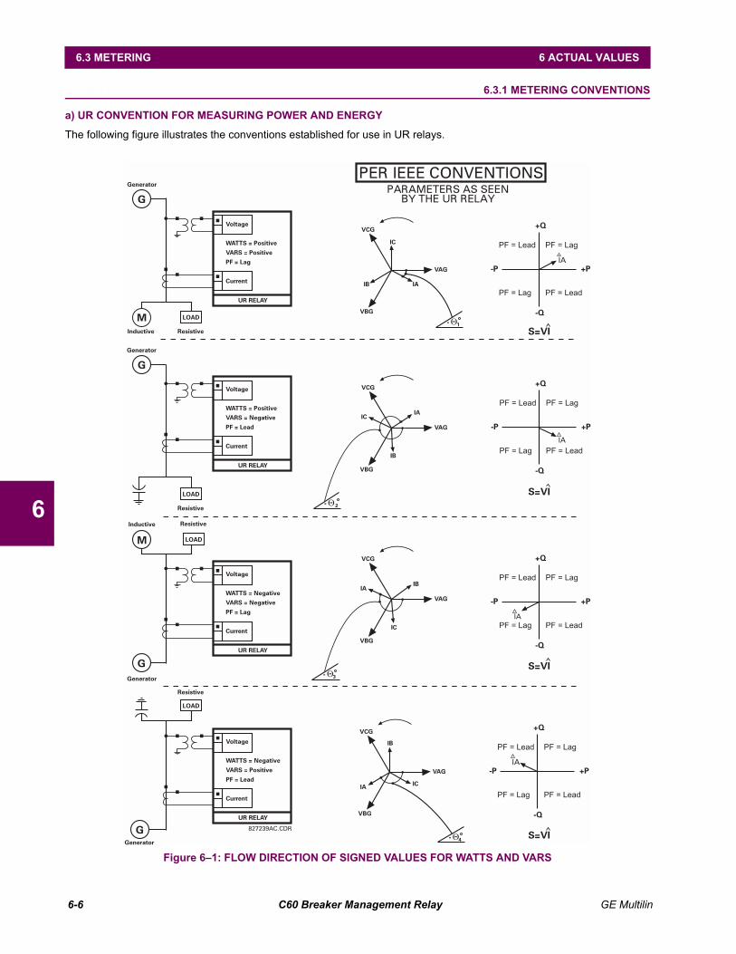
6-6 C60 Breaker Management Relay GE Multilin
6.3 METERING 6 ACTUAL VALUES
6
6.3 METERING 6.3.1 METERING CONVENTIONS
a) UR CONVENTION FOR MEASURING POWER AND ENERGY
The following figure illustrates the conventions established for use in UR relays.
Figure 61: FLOW DIRECTION OF SIGNED VALUES FOR WATTS AND VARS
827239AC.CDR
PER IEEE CONVENTIONSPARAMETERS AS SEEN
BY THE UR RELAY
Voltage
WATTS = PositiveVARS = PositivePF = Lag
Current
Voltage
WATTS = PositiveVARS = NegativePF = Lead
Current
Voltage
WATTS = NegativeVARS = NegativePF = Lag
Current
Voltage
WATTS = NegativeVARS = PositivePF = Lead
Current
Generator
Generator
Inductive
Inductive Resistive
Resistive
Generator
Generator
UR RELAY
UR RELAY
UR RELAY
UR RELAY
G
G
M
M
G
G
VCG
IC
VAG
IA
VBG
IB
1-
VCG
IC
VAG
IA
VBG
IB
2-
VCG
IC
VAG
IA
VBG
IB
3-
VCG
IC
VAG
IA
VBG
IB
4-
+Q
+Q
+Q
+Q
PF = Lead
PF = Lead
PF = Lead
PF = Lead
PF = Lag
PF = Lag
PF = Lag
PF = Lag
PF = Lag
PF = Lag
PF = Lag
PF = Lag
PF = Lead
PF = Lead
PF = Lead
PF = Lead
-Q
-Q
-Q
-Q
-P
-P
-P
-P
+P
+P
+P
+P
IA
IA
IA
IA
S=VI
S=VI
S=VI
S=VI
LOAD
LOAD
Resistive
Resistive
LOAD
LOAD
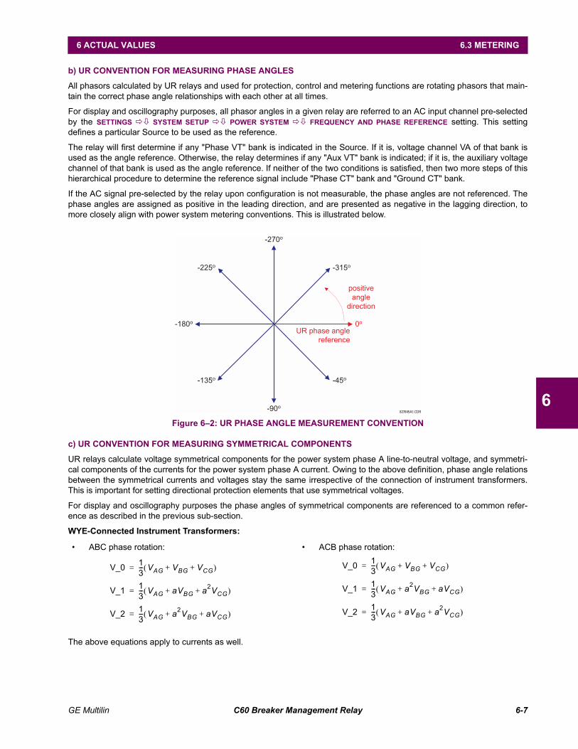
GE Multilin C60 Breaker Management Relay 6-7
6 ACTUAL VALUES 6.3 METERING
6
b) UR CONVENTION FOR MEASURING PHASE ANGLES
All phasors calculated by UR relays and used for protection, control and metering functions are rotating phasors that main-tain the correct phase angle relationships with each other at all times.
For display and oscillography purposes, all phasor angles in a given relay are referred to an AC input channel pre-selectedby the SETTINGS !" SYSTEM SETUP !" POWER SYSTEM !" FREQUENCY AND PHASE REFERENCE setting. This settingdefines a particular Source to be used as the reference.
The relay will first determine if any "Phase VT" bank is indicated in the Source. If it is, voltage channel VA of that bank isused as the angle reference. Otherwise, the relay determines if any "Aux VT" bank is indicated; if it is, the auxiliary voltagechannel of that bank is used as the angle reference. If neither of the two conditions is satisfied, then two more steps of thishierarchical procedure to determine the reference signal include "Phase CT" bank and "Ground CT" bank.
If the AC signal pre-selected by the relay upon configuration is not measurable, the phase angles are not referenced. Thephase angles are assigned as positive in the leading direction, and are presented as negative in the lagging direction, tomore closely align with power system metering conventions. This is illustrated below.
Figure 62: UR PHASE ANGLE MEASUREMENT CONVENTION
c) UR CONVENTION FOR MEASURING SYMMETRICAL COMPONENTS
UR relays calculate voltage symmetrical components for the power system phase A line-to-neutral voltage, and symmetri-cal components of the currents for the power system phase A current. Owing to the above definition, phase angle relationsbetween the symmetrical currents and voltages stay the same irrespective of the connection of instrument transformers.This is important for setting directional protection elements that use symmetrical voltages.
For display and oscillography purposes the phase angles of symmetrical components are referenced to a common refer-ence as described in the previous sub-section.
WYE-Connected Instrument Transformers:
The above equations apply to currents as well.
ABC phase rotation: ACB phase rotation:
827845A1.CDR
UR phase angle
reference
0o
-45o
-90o
-135o
-270o
-225o
-180o
-315o
positive
angle
direction
V_0 13--- VAG VBG VCG+ +( )=
V_1 13--- VAG aVBG a2VCG+ +( )=
V_2 13--- VAG a2VBG aVCG+ +( )=
V_0 13--- VAG VBG VCG+ +( )=
V_1 13--- VAG a2VBG aVCG+ +( )=
V_2 13--- VAG aVBG a2VCG+ +( )=
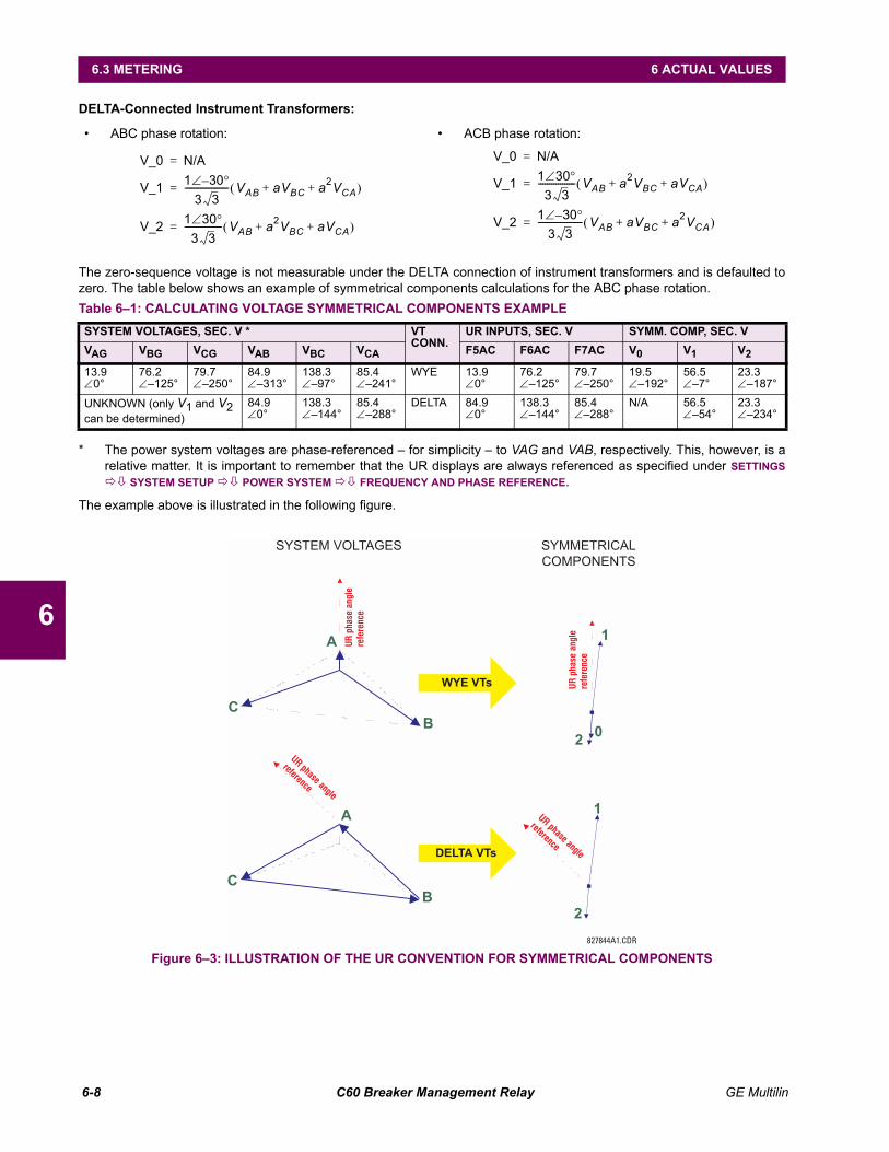
6-8 C60 Breaker Management Relay GE Multilin
6.3 METERING 6 ACTUAL VALUES
6
DELTA-Connected Instrument Transformers:
The zero-sequence voltage is not measurable under the DELTA connection of instrument transformers and is defaulted tozero. The table below shows an example of symmetrical components calculations for the ABC phase rotation.
* The power system voltages are phase-referenced for simplicity to VAG and VAB, respectively. This, however, is arelative matter. It is important to remember that the UR displays are always referenced as specified under SETTINGS!" SYSTEM SETUP !" POWER SYSTEM !" FREQUENCY AND PHASE REFERENCE.
The example above is illustrated in the following figure.
Figure 63: ILLUSTRATION OF THE UR CONVENTION FOR SYMMETRICAL COMPONENTS
ABC phase rotation: ACB phase rotation:
Table 61: CALCULATING VOLTAGE SYMMETRICAL COMPONENTS EXAMPLESYSTEM VOLTAGES, SEC. V * VT
CONN.UR INPUTS, SEC. V SYMM. COMP, SEC. V
VAG VBG VCG VAB VBC VCA F5AC F6AC F7AC V0 V1 V2
13.9∠0°
76.2∠125°
79.7∠250°
84.9∠313°
138.3∠97°
85.4∠241°
WYE 13.9∠0°
76.2∠125°
79.7∠250°
19.5∠192°
56.5∠7°
23.3∠187°
UNKNOWN (only V1 and V2 can be determined)
84.9∠0°
138.3∠144°
85.4∠288°
DELTA 84.9∠0°
138.3∠144°
85.4∠288°
N/A 56.5∠54°
23.3∠234°
V_0 N/A=
V_1 1 30– °∠3 3
-------------------- VAB aVBC a2VCA+ +( )=
V_2 1 30°∠3 3----------------- VAB a2VBC aVCA+ +( )=
V_0 N/A=
V_1 1 30°∠3 3----------------- VAB a2VBC aVCA+ +( )=
V_2 1 30– °∠3 3
-------------------- VAB aVBC a2VCA+ +( )=
827844A1.CDR
A
B
C
WYE VTs
1
02
A
B
C
DELTA VTs
1
2
SYSTEM VOLTAGES SYMMETRICAL
COMPONENTS
UR p
hase
ang
lere
fere
nce
UR p
hase
ang
lere
fere
nce
UR phase angle
reference
UR phase angle
reference
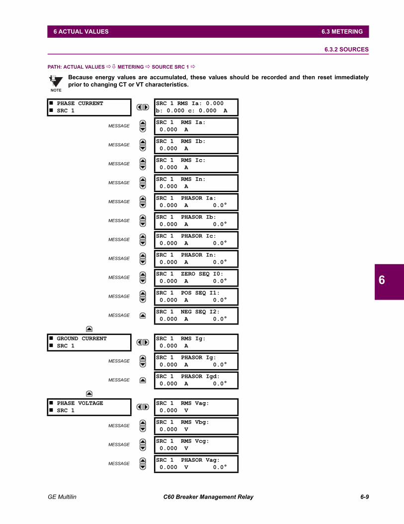
GE Multilin C60 Breaker Management Relay 6-9
6 ACTUAL VALUES 6.3 METERING
6
6.3.2 SOURCES
PATH: ACTUAL VALUES !" METERING ! SOURCE SRC 1 !
Because energy values are accumulated, these values should be recorded and then reset immediatelyprior to changing CT or VT characteristics.
# PHASE CURRENT# SRC 1
SRC 1 RMS Ia: 0.000b: 0.000 c: 0.000 A
MESSAGESRC 1 RMS Ia:0.000 A
MESSAGESRC 1 RMS Ib:0.000 A
MESSAGESRC 1 RMS Ic:0.000 A
MESSAGESRC 1 RMS In:0.000 A
MESSAGESRC 1 PHASOR Ia:0.000 A 0.0°
MESSAGESRC 1 PHASOR Ib:0.000 A 0.0°
MESSAGESRC 1 PHASOR Ic:0.000 A 0.0°
MESSAGESRC 1 PHASOR In:0.000 A 0.0°
MESSAGESRC 1 ZERO SEQ I0:0.000 A 0.0°
MESSAGESRC 1 POS SEQ I1:0.000 A 0.0°
MESSAGESRC 1 NEG SEQ I2:0.000 A 0.0°
# GROUND CURRENT# SRC 1
SRC 1 RMS Ig:0.000 A
MESSAGESRC 1 PHASOR Ig:0.000 A 0.0°
MESSAGESRC 1 PHASOR Igd:0.000 A 0.0°
# PHASE VOLTAGE# SRC 1
SRC 1 RMS Vag:0.000 V
MESSAGESRC 1 RMS Vbg:0.000 V
MESSAGESRC 1 RMS Vcg:0.000 V
MESSAGESRC 1 PHASOR Vag:0.000 V 0.0°
NOTE
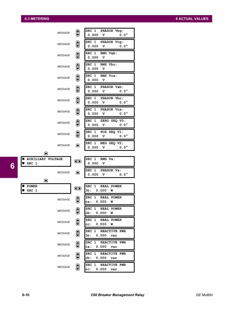
6-10 C60 Breaker Management Relay GE Multilin
6.3 METERING 6 ACTUAL VALUES
6
MESSAGESRC 1 PHASOR Vbg:0.000 V 0.0°
MESSAGESRC 1 PHASOR Vcg:0.000 V 0.0°
MESSAGESRC 1 RMS Vab:0.000 V
MESSAGESRC 1 RMS Vbc:0.000 V
MESSAGESRC 1 RMS Vca:0.000 V
MESSAGESRC 1 PHASOR Vab:0.000 V 0.0°
MESSAGESRC 1 PHASOR Vbc:0.000 V 0.0°
MESSAGESRC 1 PHASOR Vca:0.000 V 0.0°
MESSAGESRC 1 ZERO SEQ V0:0.000 V 0.0°
MESSAGESRC 1 POS SEQ V1:0.000 V 0.0°
MESSAGESRC 1 NEG SEQ V2:0.000 V 0.0°
# AUXILIARY VOLTAGE# SRC 1
SRC 1 RMS Vx:0.000 V
MESSAGESRC 1 PHASOR Vx:0.000 V 0.0°
# POWER# SRC 1
SRC 1 REAL POWER3φ: 0.000 W
MESSAGESRC 1 REAL POWERφa: 0.000 W
MESSAGESRC 1 REAL POWERφb: 0.000 W
MESSAGESRC 1 REAL POWERφc: 0.000 W
MESSAGESRC 1 REACTIVE PWR3φ: 0.000 var
MESSAGESRC 1 REACTIVE PWRφa: 0.000 var
MESSAGESRC 1 REACTIVE PWRφb: 0.000 var
MESSAGESRC 1 REACTIVE PWRφc: 0.000 var
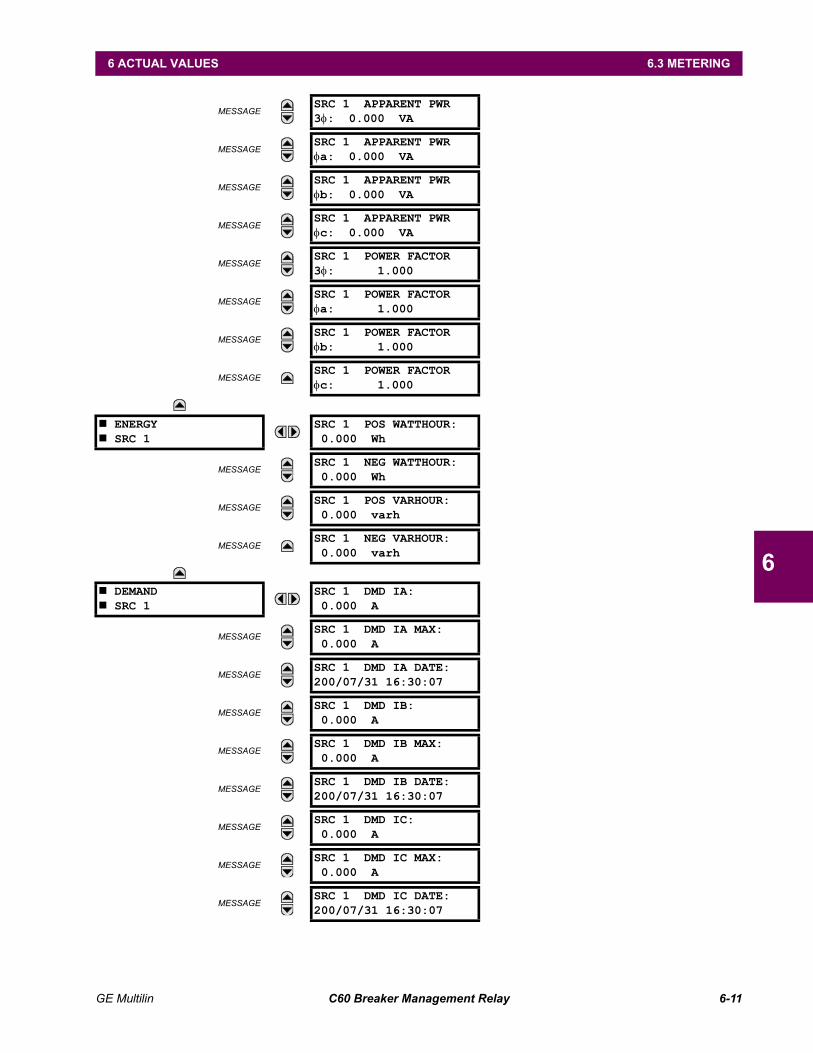
GE Multilin C60 Breaker Management Relay 6-11
6 ACTUAL VALUES 6.3 METERING
6
MESSAGESRC 1 APPARENT PWR3φ: 0.000 VA
MESSAGESRC 1 APPARENT PWRφa: 0.000 VA
MESSAGESRC 1 APPARENT PWRφb: 0.000 VA
MESSAGESRC 1 APPARENT PWRφc: 0.000 VA
MESSAGESRC 1 POWER FACTOR3φ: 1.000
MESSAGESRC 1 POWER FACTORφa: 1.000
MESSAGESRC 1 POWER FACTORφb: 1.000
MESSAGESRC 1 POWER FACTORφc: 1.000
# ENERGY# SRC 1
SRC 1 POS WATTHOUR:0.000 Wh
MESSAGESRC 1 NEG WATTHOUR:0.000 Wh
MESSAGESRC 1 POS VARHOUR:0.000 varh
MESSAGESRC 1 NEG VARHOUR:0.000 varh
# DEMAND# SRC 1
SRC 1 DMD IA:0.000 A
MESSAGESRC 1 DMD IA MAX:0.000 A
MESSAGESRC 1 DMD IA DATE:200/07/31 16:30:07
MESSAGESRC 1 DMD IB:0.000 A
MESSAGESRC 1 DMD IB MAX:0.000 A
MESSAGESRC 1 DMD IB DATE:200/07/31 16:30:07
MESSAGESRC 1 DMD IC:0.000 A
MESSAGESRC 1 DMD IC MAX:0.000 A
MESSAGESRC 1 DMD IC DATE:200/07/31 16:30:07
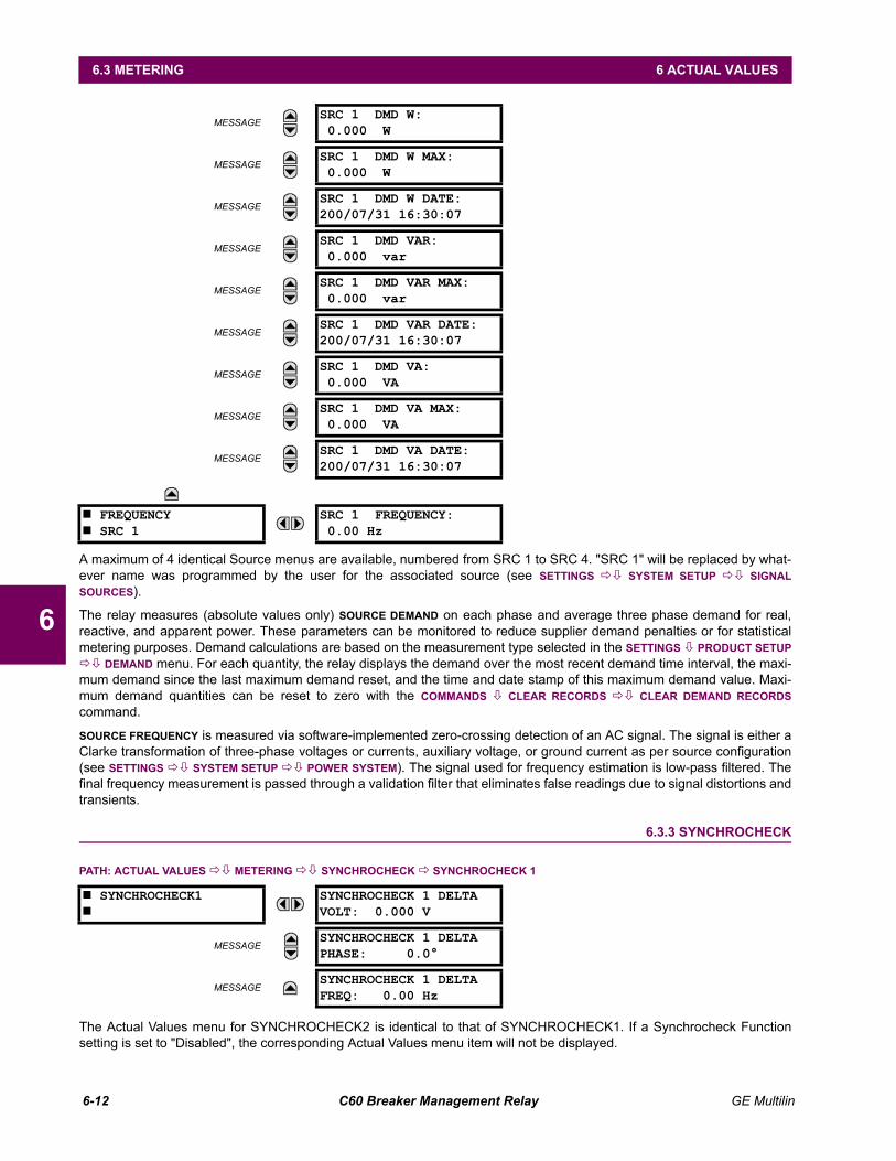
6-12 C60 Breaker Management Relay GE Multilin
6.3 METERING 6 ACTUAL VALUES
6
A maximum of 4 identical Source menus are available, numbered from SRC 1 to SRC 4. "SRC 1" will be replaced by what-ever name was programmed by the user for the associated source (see SETTINGS !" SYSTEM SETUP !" SIGNALSOURCES).
The relay measures (absolute values only) SOURCE DEMAND on each phase and average three phase demand for real,reactive, and apparent power. These parameters can be monitored to reduce supplier demand penalties or for statisticalmetering purposes. Demand calculations are based on the measurement type selected in the SETTINGS " PRODUCT SETUP!" DEMAND menu. For each quantity, the relay displays the demand over the most recent demand time interval, the maxi-mum demand since the last maximum demand reset, and the time and date stamp of this maximum demand value. Maxi-mum demand quantities can be reset to zero with the COMMANDS " CLEAR RECORDS !" CLEAR DEMAND RECORDScommand.
SOURCE FREQUENCY is measured via software-implemented zero-crossing detection of an AC signal. The signal is either aClarke transformation of three-phase voltages or currents, auxiliary voltage, or ground current as per source configuration(see SETTINGS !" SYSTEM SETUP !" POWER SYSTEM). The signal used for frequency estimation is low-pass filtered. Thefinal frequency measurement is passed through a validation filter that eliminates false readings due to signal distortions andtransients.
6.3.3 SYNCHROCHECK
PATH: ACTUAL VALUES !" METERING !" SYNCHROCHECK ! SYNCHROCHECK 1
The Actual Values menu for SYNCHROCHECK2 is identical to that of SYNCHROCHECK1. If a Synchrocheck Functionsetting is set to "Disabled", the corresponding Actual Values menu item will not be displayed.
MESSAGESRC 1 DMD W:0.000 W
MESSAGESRC 1 DMD W MAX:0.000 W
MESSAGESRC 1 DMD W DATE:200/07/31 16:30:07
MESSAGESRC 1 DMD VAR:0.000 var
MESSAGESRC 1 DMD VAR MAX:0.000 var
MESSAGESRC 1 DMD VAR DATE:200/07/31 16:30:07
MESSAGESRC 1 DMD VA:0.000 VA
MESSAGESRC 1 DMD VA MAX:0.000 VA
MESSAGESRC 1 DMD VA DATE:200/07/31 16:30:07
# FREQUENCY# SRC 1
SRC 1 FREQUENCY:0.00 Hz
# SYNCHROCHECK1#
SYNCHROCHECK 1 DELTAVOLT: 0.000 V
MESSAGESYNCHROCHECK 1 DELTAPHASE: 0.0°
MESSAGESYNCHROCHECK 1 DELTAFREQ: 0.00 Hz
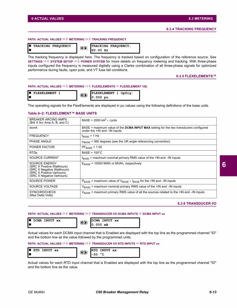
GE Multilin C60 Breaker Management Relay 6-13
6 ACTUAL VALUES 6.3 METERING
6
6.3.4 TRACKING FREQUENCY
PATH: ACTUAL VALUES !" METERING !" TRACKING FREQUENCY
The tracking frequency is displayed here. The frequency is tracked based on configuration of the reference source. SeeSETTINGS !" SYSTEM SETUP !" POWER SYSTEM for more details on frequency metering and tracking. With three-phaseinputs configured the frequency is measured digitally using a Clarke combination of all three-phase signals for optimizedperformance during faults, open pole, and VT fuse fail conditions.
6.3.5 FLEXELEMENTS
PATH: ACTUAL VALUES !" METERING !" FLEXELEMENTS ! FLEXELEMENT 1(8)
The operating signals for the FlexElements are displayed in pu values using the following definitions of the base units.
6.3.6 TRANSDUCER I/O
PATH: ACTUAL VALUES !" METERING !" TRANSDUCER I/O DCMA INPUTS ! DCMA INPUT xx
Actual values for each DCMA input channel that is Enabled are displayed with the top line as the programmed channel "ID"and the bottom line as the value followed by the programmed units.
PATH: ACTUAL VALUES !" METERING !" TRANSDUCER I/O RTD INPUTS ! RTD INPUT xx
Actual values for each RTD input channel that is Enabled are displayed with the top line as the programmed channel "ID"and the bottom line as the value.
# TRACKING FREQUENCY#
TRACKING FREQUENCY:60.00 Hz
# FLEXELEMENT 1#
FLEXELEMENT 1 OpSig:0.000 pu
Table 62: FLEXELEMENT BASE UNITSBREAKER ARCING AMPS(Brk X Arc Amp A, B, and C)
BASE = 2000 kA2 × cycle
dcmA BASE = maximum value of the DCMA INPUT MAX setting for the two transducers configured under the +IN and IN inputs.
FREQUENCY fBASE = 1 Hz
PHASE ANGLE ϕBASE = 360 degrees (see the UR angle referencing convention)
POWER FACTOR PFBASE = 1.00
RTDs BASE = 100°CSOURCE CURRENT IBASE = maximum nominal primary RMS value of the +IN and IN inputs
SOURCE ENERGY(SRC X Positive Watthours)(SRC X Negative Watthours)(SRC X Positive Varhours)(SRC X Negative Varhours)
EBASE = 10000 MWh or MVAh, respectively
SOURCE POWER PBASE = maximum value of VBASE × IBASE for the +IN and IN inputs
SOURCE VOLTAGE VBASE = maximum nominal primary RMS value of the +IN and IN inputs
SYNCHROCHECK(Max Delta Volts)
VBASE = maximum primary RMS value of all the sources related to the +IN and IN inputs
# DCMA INPUT xx#
DCMA INPUT xx0.000 mA
# RTD INPUT xx#
RTD INPUT xx-50 °C
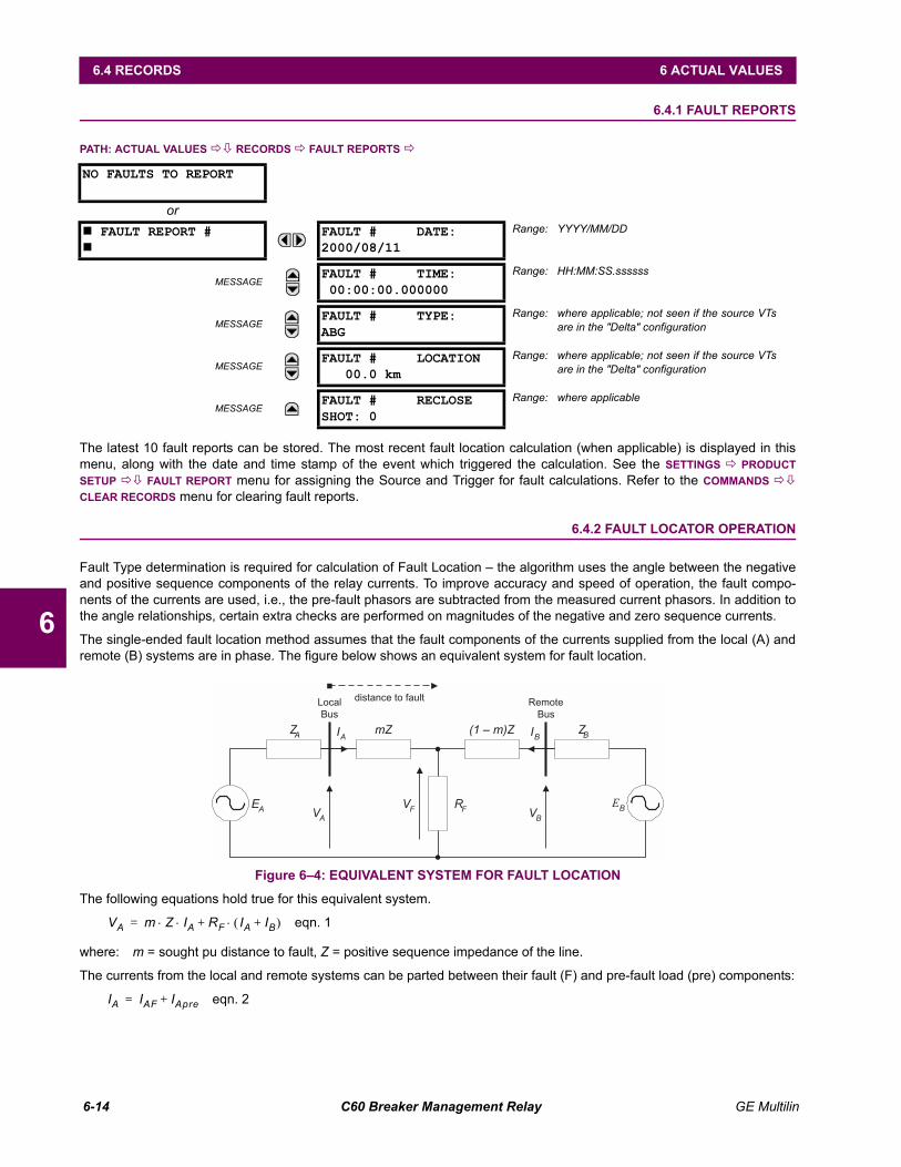
6-14 C60 Breaker Management Relay GE Multilin
6.4 RECORDS 6 ACTUAL VALUES
6
6.4 RECORDS 6.4.1 FAULT REPORTS
PATH: ACTUAL VALUES !" RECORDS ! FAULT REPORTS !
The latest 10 fault reports can be stored. The most recent fault location calculation (when applicable) is displayed in thismenu, along with the date and time stamp of the event which triggered the calculation. See the SETTINGS ! PRODUCTSETUP !" FAULT REPORT menu for assigning the Source and Trigger for fault calculations. Refer to the COMMANDS !"CLEAR RECORDS menu for clearing fault reports.
6.4.2 FAULT LOCATOR OPERATION
Fault Type determination is required for calculation of Fault Location the algorithm uses the angle between the negativeand positive sequence components of the relay currents. To improve accuracy and speed of operation, the fault compo-nents of the currents are used, i.e., the pre-fault phasors are subtracted from the measured current phasors. In addition tothe angle relationships, certain extra checks are performed on magnitudes of the negative and zero sequence currents.
The single-ended fault location method assumes that the fault components of the currents supplied from the local (A) andremote (B) systems are in phase. The figure below shows an equivalent system for fault location.
Figure 64: EQUIVALENT SYSTEM FOR FAULT LOCATION
The following equations hold true for this equivalent system.
eqn. 1
where: m = sought pu distance to fault, Z = positive sequence impedance of the line.
The currents from the local and remote systems can be parted between their fault (F) and pre-fault load (pre) components:
eqn. 2
NO FAULTS TO REPORT
or# FAULT REPORT ##
FAULT # DATE:2000/08/11
Range: YYYY/MM/DD
MESSAGEFAULT # TIME:00:00:00.000000
Range: HH:MM:SS.ssssss
MESSAGEFAULT # TYPE:ABG
Range: where applicable; not seen if the source VTsare in the "Delta" configuration
MESSAGEFAULT # LOCATION
00.0 kmRange: where applicable; not seen if the source VTs
are in the "Delta" configuration
MESSAGEFAULT # RECLOSESHOT: 0
Range: where applicable
mZ (1 – m)Z
RF
ZA
ZB
EA
EB
VA
VB
VF
IA
IB
Local
Bus
Remote
Bus
distance to fault
VA m Z IA⋅ ⋅ RF IA IB+( )⋅+=
IA IAF IApre+=
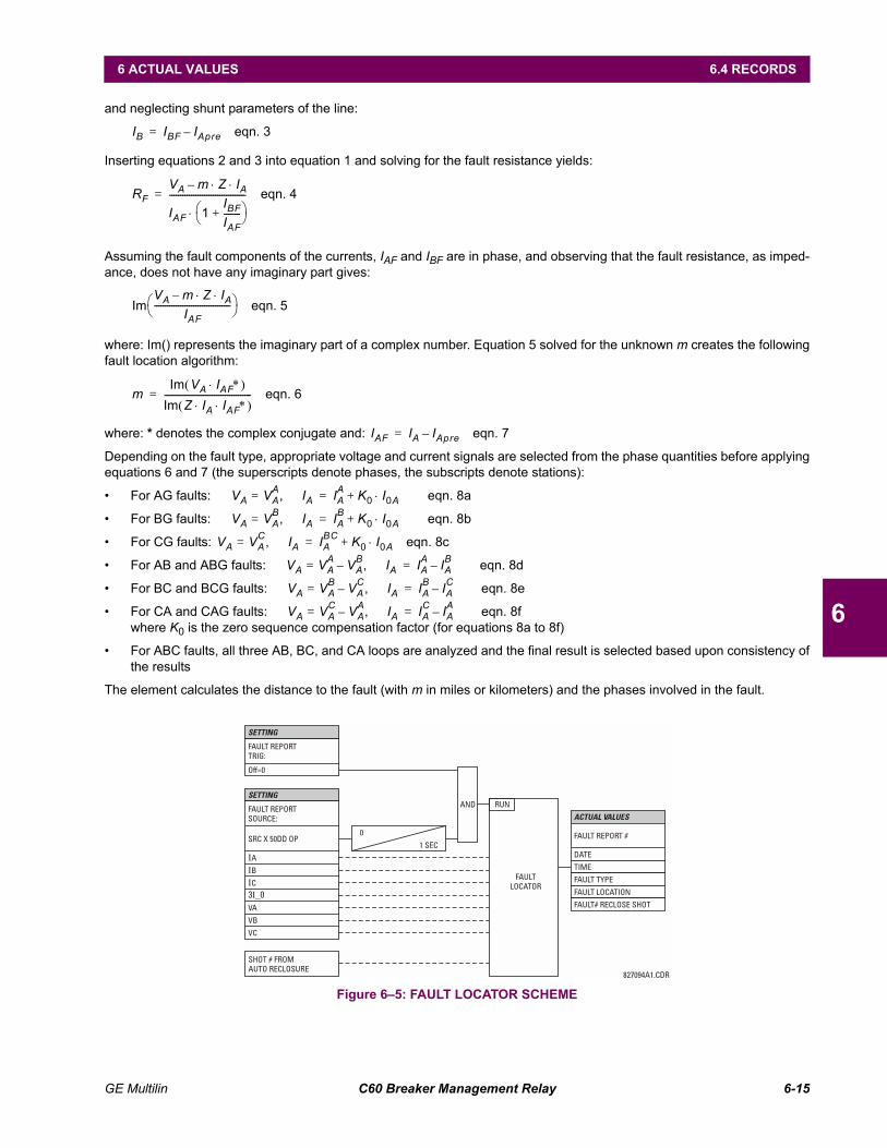
GE Multilin C60 Breaker Management Relay 6-15
6 ACTUAL VALUES 6.4 RECORDS
6
and neglecting shunt parameters of the line:
eqn. 3
Inserting equations 2 and 3 into equation 1 and solving for the fault resistance yields:
eqn. 4
Assuming the fault components of the currents, IAF and IBF are in phase, and observing that the fault resistance, as imped-ance, does not have any imaginary part gives:
eqn. 5
where: Im() represents the imaginary part of a complex number. Equation 5 solved for the unknown m creates the followingfault location algorithm:
eqn. 6
where: * denotes the complex conjugate and: eqn. 7
Depending on the fault type, appropriate voltage and current signals are selected from the phase quantities before applyingequations 6 and 7 (the superscripts denote phases, the subscripts denote stations):
For AG faults: eqn. 8a
For BG faults: eqn. 8b
For CG faults: eqn. 8c
For AB and ABG faults: eqn. 8d
For BC and BCG faults: eqn. 8e
For CA and CAG faults: eqn. 8fwhere K0 is the zero sequence compensation factor (for equations 8a to 8f)
For ABC faults, all three AB, BC, and CA loops are analyzed and the final result is selected based upon consistency ofthe results
The element calculates the distance to the fault (with m in miles or kilometers) and the phases involved in the fault.
Figure 65: FAULT LOCATOR SCHEME
IB IBF IApre–=
RFVA m Z IA⋅ ⋅–
IAF 1IBFIAF--------+
⋅-----------------------------------=
ImVA m Z IA⋅ ⋅–
IAF-----------------------------------
mIm VA IAF∗⋅( )
Im Z IA IAF∗⋅ ⋅( )----------------------------------------=
IAF IA IApre–=
VA VAA
= , IA IAA K0 I0A⋅+=
VA VAB
= , IA IAB K0 I0A⋅+=
VA VAC
= , IA IABC K0 I0A⋅+=
VA VAA VA
B–= , IA IA
A IAB
–=
VA VAB VA
C–= , IA IA
B IAC
–=
VA VAC VA
A–= , IA IA
C IAA
–=
SETTING
SETTING
FAULT REPORTSOURCE:
SHOT # FROMAUTO RECLOSURE
FAULT REPORTTRIG:
IA
3 _0IICIB
SRC X 50DD OP
VA
VC
VB
827094A1.CDR
Off=0
AND
FAULTLOCATOR
RUN
0
1 SEC
ACTUAL VALUES
DATE
TIME
FAULT TYPE
FAULT LOCATION
FAULT# RECLOSE SHOT
FAULT REPORT #
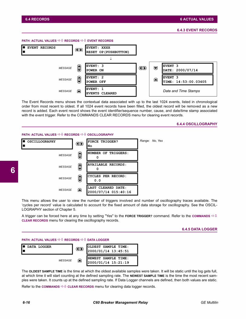
6-16 C60 Breaker Management Relay GE Multilin
6.4 RECORDS 6 ACTUAL VALUES
6
6.4.3 EVENT RECORDS
PATH: ACTUAL VALUES !" RECORDS !" EVENT RECORDS
The Event Records menu shows the contextual data associated with up to the last 1024 events, listed in chronologicalorder from most recent to oldest. If all 1024 event records have been filled, the oldest record will be removed as a newrecord is added. Each event record shows the event identifier/sequence number, cause, and date/time stamp associatedwith the event trigger. Refer to the COMMANDS CLEAR RECORDS menu for clearing event records.
6.4.4 OSCILLOGRAPHY
PATH: ACTUAL VALUES !" RECORDS !" OSCILLOGRAPHY
This menu allows the user to view the number of triggers involved and number of oscillography traces available. Thecycles per record value is calculated to account for the fixed amount of data storage for oscillography. See the OSCIL-LOGRAPHY section of Chapter 5.
A trigger can be forced here at any time by setting "Yes" to the FORCE TRIGGER? command. Refer to the COMMANDS !"CLEAR RECORDS menu for clearing the oscillography records.
6.4.5 DATA LOGGER
PATH: ACTUAL VALUES !" RECORDS !" DATA LOGGER
The OLDEST SAMPLE TIME is the time at which the oldest available samples were taken. It will be static until the log gets full,at which time it will start counting at the defined sampling rate. The NEWEST SAMPLE TIME is the time the most recent sam-ples were taken. It counts up at the defined sampling rate. If Data Logger channels are defined, then both values are static.
Refer to the COMMANDS !" CLEAR RECORDS menu for clearing data logger records.
# EVENT RECORDS#
EVENT: XXXXRESET OP(PUSHBUTTON)
↓
MESSAGEEVENT: 3POWER ON
EVENT 3DATE: 2000/07/14
MESSAGEEVENT: 2POWER OFF
EVENT 3TIME: 14:53:00.03405
MESSAGEEVENT: 1EVENTS CLEARED
Date and Time Stamps
# OSCILLOGRAPHY#
FORCE TRIGGER?No
Range: No, Yes
MESSAGENUMBER OF TRIGGERS:
0
MESSAGEAVAILABLE RECORDS:
0
MESSAGECYCLES PER RECORD:
0.0
MESSAGELAST CLEARED DATE:2000/07/14 015:40:16
# DATA LOGGER#
OLDEST SAMPLE TIME:2000/01/14 13:45:51
MESSAGENEWEST SAMPLE TIME:2000/01/14 15:21:19
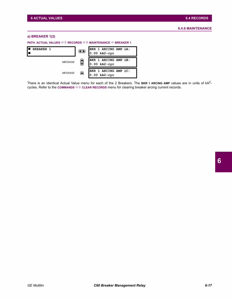
GE Multilin C60 Breaker Management Relay 6-17
6 ACTUAL VALUES 6.4 RECORDS
6
6.4.6 MAINTENANCE
a) BREAKER 1(2)
PATH: ACTUAL VALUES !" RECORDS !" MAINTENANCE ! BREAKER 1
There is an identical Actual Value menu for each of the 2 Breakers. The BKR 1 ARCING AMP values are in units of kA2-cycles. Refer to the COMMANDS !" CLEAR RECORDS menu for clearing breaker arcing current records.
# BREAKER 1#
BKR 1 ARCING AMP φA:0.00 kA2-cyc
MESSAGEBKR 1 ARCING AMP φB:0.00 kA2-cyc
MESSAGEBKR 1 ARCING AMP φC:0.00 kA2-cyc
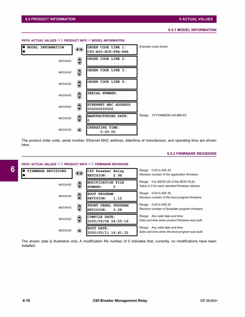
6-18 C60 Breaker Management Relay GE Multilin
6.5 PRODUCT INFORMATION 6 ACTUAL VALUES
6
6.5 PRODUCT INFORMATION 6.5.1 MODEL INFORMATION
PATH: ACTUAL VALUES !" PRODUCT INFO ! MODEL INFORMATION
The product order code, serial number, Ethernet MAC address, date/time of manufacture, and operating time are shownhere.
6.5.2 FIRMWARE REVISIONS
PATH: ACTUAL VALUES !" PRODUCT INFO !" FIRMWARE REVISIONS
The shown data is illustrative only. A modification file number of 0 indicates that, currently, no modifications have beeninstalled.
# MODEL INFORMATION#
ORDER CODE LINE 1:C60-A00-HCH-F8A-H6A
Example code shown
MESSAGEORDER CODE LINE 2:
MESSAGEORDER CODE LINE 3:
MESSAGEORDER CODE LINE 4:
MESSAGESERIAL NUMBER:
MESSAGEETHERNET MAC ADDRESS000000000000
MESSAGEMANUFACTURING DATE:0
Range: YYYY/MM/DD HH:MM:SS
MESSAGEOPERATING TIME:
0:00:00
# FIRMWARE REVISIONS#
C60 Breaker RelayREVISION: 2.9X
Range: 0.00 to 655.35Revision number of the application firmware.
MESSAGEMODIFICATION FILENUMBER: 0
Range: 0 to 65535 (ID of the MOD FILE)Value is 0 for each standard firmware release.
MESSAGEBOOT PROGRAMREVISION: 1.12
Range: 0.00 to 655.35Revision number of the boot program firmware.
MESSAGEFRONT PANEL PROGRAMREVISION: 0.08
Range: 0.00 to 655.35Revision number of faceplate program firmware.
MESSAGECOMPILE DATE:2000/09/08 04:55:16
Range: Any valid date and time.Date and time when product firmware was built.
MESSAGEBOOT DATE:2000/05/11 16:41:32
Range: Any valid date and time.Date and time when the boot program was built.
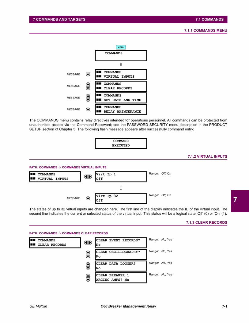
GE Multilin C60 Breaker Management Relay 7-1
7 COMMANDS AND TARGETS 7.1 COMMANDS
7
7 COMMANDS AND TARGETS 7.1 COMMANDS 7.1.1 COMMANDS MENU
The COMMANDS menu contains relay directives intended for operations personnel. All commands can be protected fromunauthorized access via the Command Password; see the PASSWORD SECURITY menu description in the PRODUCTSETUP section of Chapter 5. The following flash message appears after successfully command entry:
7.1.2 VIRTUAL INPUTS
PATH: COMMANDS " COMMANDS VIRTUAL INPUTS
The states of up to 32 virtual inputs are changed here. The first line of the display indicates the ID of the virtual input. Thesecond line indicates the current or selected status of the virtual input. This status will be a logical state Off (0) or On (1).
7.1.3 CLEAR RECORDS
PATH: COMMANDS " COMMANDS CLEAR RECORDS
COMMANDS
"
MESSAGE## COMMANDS## VIRTUAL INPUTS
MESSAGE## COMMANDS## CLEAR RECORDS
MESSAGE## COMMANDS## SET DATE AND TIME
MESSAGE## COMMANDS## RELAY MAINTENANCE
COMMANDEXECUTED
## COMMANDS## VIRTUAL INPUTS
Virt Ip 1Off
Range: Off, On
↓↓
MESSAGEVirt Ip 32Off
Range: Off, On
## COMMANDS## CLEAR RECORDS
CLEAR EVENT RECORDS?No
Range: No, Yes
CLEAR OSCILLOGRAPHY?No
Range: No, Yes
CLEAR DATA LOGGER?No
Range: No, Yes
CLEAR BREAKER 1ARCING AMPS? No
Range: No, Yes
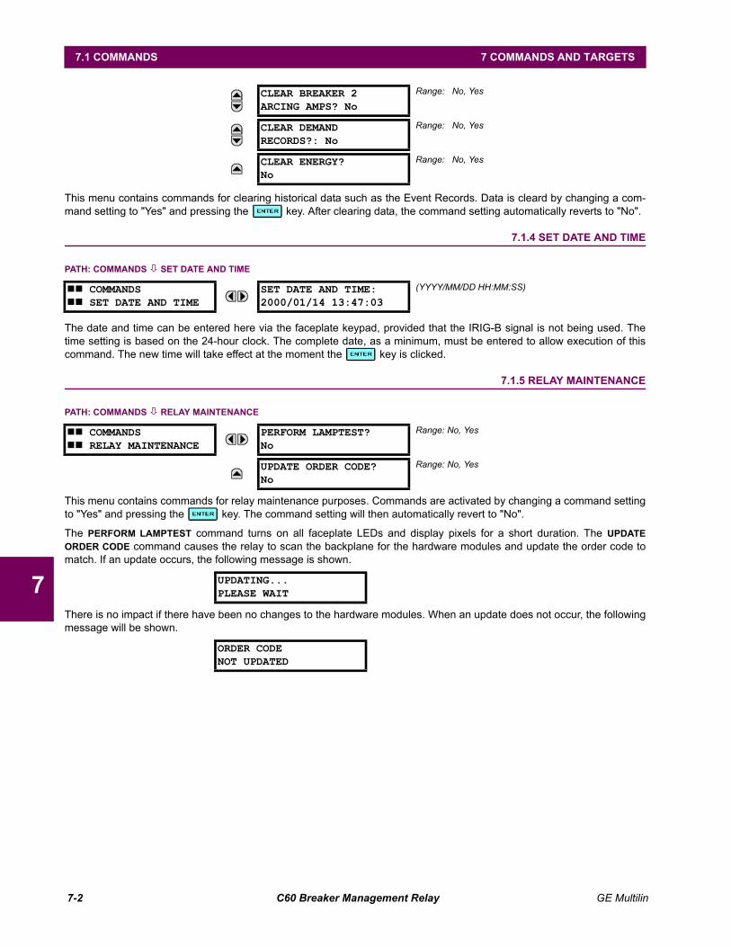
7-2 C60 Breaker Management Relay GE Multilin
7.1 COMMANDS 7 COMMANDS AND TARGETS
7
This menu contains commands for clearing historical data such as the Event Records. Data is cleard by changing a com-mand setting to "Yes" and pressing the key. After clearing data, the command setting automatically reverts to "No".
7.1.4 SET DATE AND TIME
PATH: COMMANDS " SET DATE AND TIME
The date and time can be entered here via the faceplate keypad, provided that the IRIG-B signal is not being used. Thetime setting is based on the 24-hour clock. The complete date, as a minimum, must be entered to allow execution of thiscommand. The new time will take effect at the moment the key is clicked.
7.1.5 RELAY MAINTENANCE
PATH: COMMANDS " RELAY MAINTENANCE
This menu contains commands for relay maintenance purposes. Commands are activated by changing a command settingto "Yes" and pressing the key. The command setting will then automatically revert to "No".
The PERFORM LAMPTEST command turns on all faceplate LEDs and display pixels for a short duration. The UPDATEORDER CODE command causes the relay to scan the backplane for the hardware modules and update the order code tomatch. If an update occurs, the following message is shown.
There is no impact if there have been no changes to the hardware modules. When an update does not occur, the followingmessage will be shown.
CLEAR BREAKER 2ARCING AMPS? No
Range: No, Yes
CLEAR DEMANDRECORDS?: No
Range: No, Yes
CLEAR ENERGY?No
Range: No, Yes
## COMMANDS## SET DATE AND TIME
SET DATE AND TIME:2000/01/14 13:47:03
(YYYY/MM/DD HH:MM:SS)
## COMMANDS## RELAY MAINTENANCE
PERFORM LAMPTEST?No
Range: No, Yes
UPDATE ORDER CODE?No
Range: No, Yes
UPDATING...PLEASE WAIT
ORDER CODENOT UPDATED
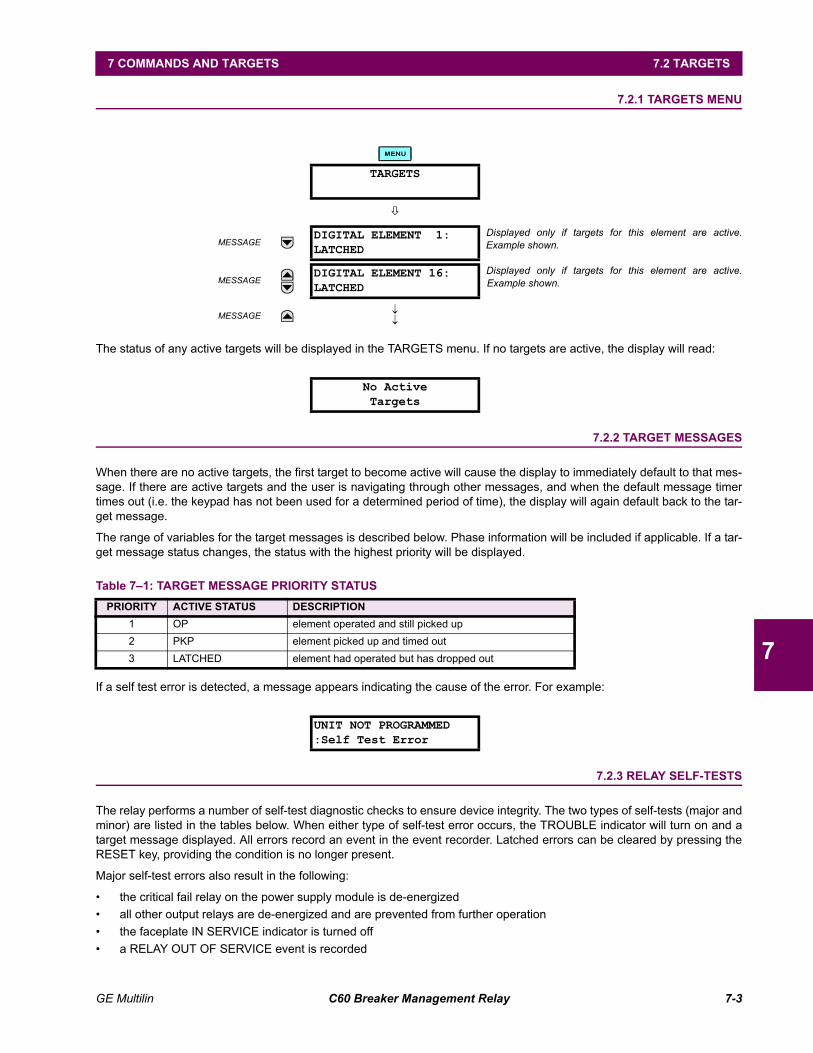
GE Multilin C60 Breaker Management Relay 7-3
7 COMMANDS AND TARGETS 7.2 TARGETS
7
7.2 TARGETS 7.2.1 TARGETS MENU
The status of any active targets will be displayed in the TARGETS menu. If no targets are active, the display will read:
7.2.2 TARGET MESSAGES
When there are no active targets, the first target to become active will cause the display to immediately default to that mes-sage. If there are active targets and the user is navigating through other messages, and when the default message timertimes out (i.e. the keypad has not been used for a determined period of time), the display will again default back to the tar-get message.
The range of variables for the target messages is described below. Phase information will be included if applicable. If a tar-get message status changes, the status with the highest priority will be displayed.
If a self test error is detected, a message appears indicating the cause of the error. For example:
7.2.3 RELAY SELF-TESTS
The relay performs a number of self-test diagnostic checks to ensure device integrity. The two types of self-tests (major andminor) are listed in the tables below. When either type of self-test error occurs, the TROUBLE indicator will turn on and atarget message displayed. All errors record an event in the event recorder. Latched errors can be cleared by pressing theRESET key, providing the condition is no longer present.
Major self-test errors also result in the following:
the critical fail relay on the power supply module is de-energized all other output relays are de-energized and are prevented from further operation the faceplate IN SERVICE indicator is turned off a RELAY OUT OF SERVICE event is recorded
TARGETS
"
MESSAGEDIGITAL ELEMENT 1:LATCHED
Displayed only if targets for this element are active.Example shown.
MESSAGEDIGITAL ELEMENT 16:LATCHED
Displayed only if targets for this element are active.Example shown.
MESSAGE ↓↓
No ActiveTargets
Table 71: TARGET MESSAGE PRIORITY STATUSPRIORITY ACTIVE STATUS DESCRIPTION
1 OP element operated and still picked up2 PKP element picked up and timed out3 LATCHED element had operated but has dropped out
UNIT NOT PROGRAMMED:Self Test Error
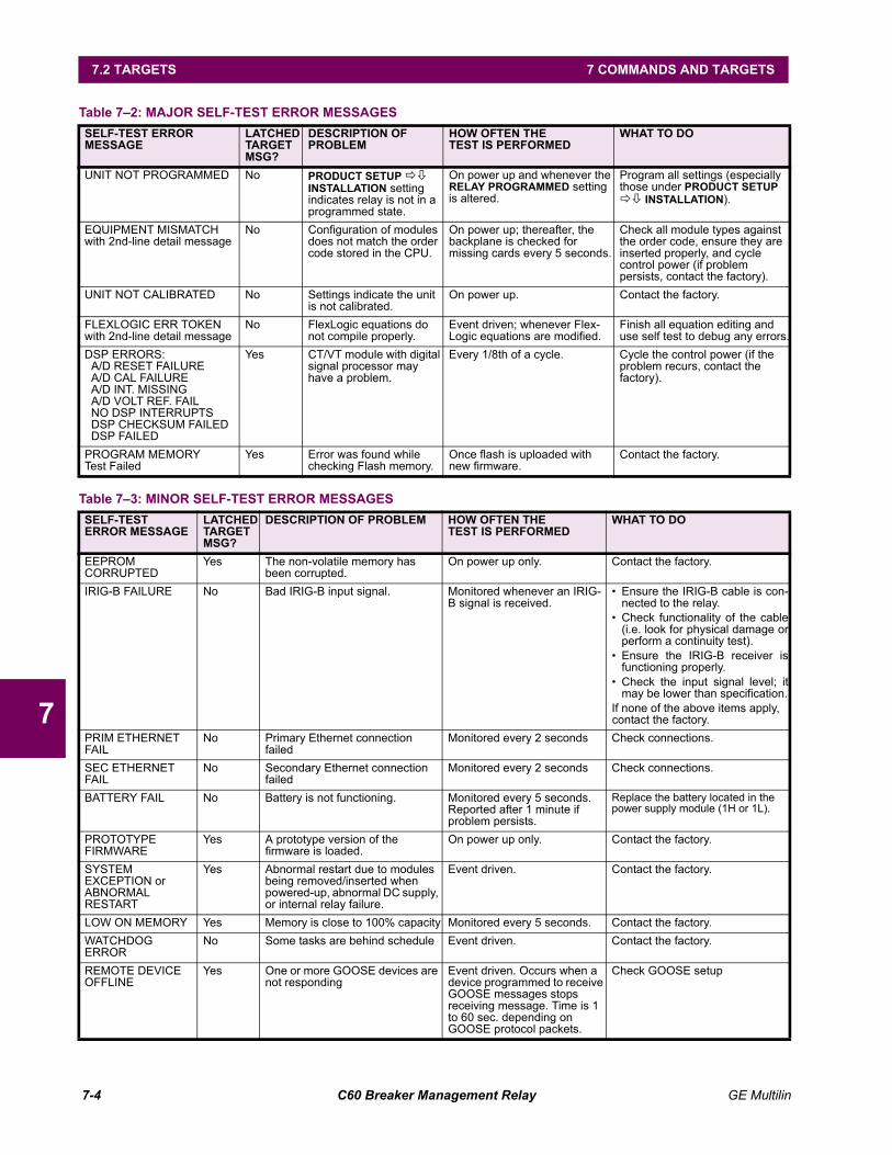
7-4 C60 Breaker Management Relay GE Multilin
7.2 TARGETS 7 COMMANDS AND TARGETS
7
Table 72: MAJOR SELF-TEST ERROR MESSAGES SELF-TEST ERROR MESSAGE
LATCHED TARGET MSG?
DESCRIPTION OF PROBLEM
HOW OFTEN THETEST IS PERFORMED
WHAT TO DO
UNIT NOT PROGRAMMED No PRODUCT SETUP !" INSTALLATION setting indicates relay is not in a programmed state.
On power up and whenever the RELAY PROGRAMMED setting is altered.
Program all settings (especially those under PRODUCT SETUP !" INSTALLATION).
EQUIPMENT MISMATCHwith 2nd-line detail message
No Configuration of modules does not match the order code stored in the CPU.
On power up; thereafter, the backplane is checked for missing cards every 5 seconds.
Check all module types against the order code, ensure they are inserted properly, and cycle control power (if problem persists, contact the factory).
UNIT NOT CALIBRATED No Settings indicate the unit is not calibrated.
On power up. Contact the factory.
FLEXLOGIC ERR TOKENwith 2nd-line detail message
No FlexLogic equations do not compile properly.
Event driven; whenever Flex-Logic equations are modified.
Finish all equation editing and use self test to debug any errors.
DSP ERRORS:A/D RESET FAILUREA/D CAL FAILUREA/D INT. MISSINGA/D VOLT REF. FAILNO DSP INTERRUPTSDSP CHECKSUM FAILEDDSP FAILED
Yes CT/VT module with digital signal processor may have a problem.
Every 1/8th of a cycle. Cycle the control power (if the problem recurs, contact the factory).
PROGRAM MEMORYTest Failed
Yes Error was found while checking Flash memory.
Once flash is uploaded with new firmware.
Contact the factory.
Table 73: MINOR SELF-TEST ERROR MESSAGES SELF-TEST ERROR MESSAGE
LATCHED TARGET MSG?
DESCRIPTION OF PROBLEM HOW OFTEN THETEST IS PERFORMED
WHAT TO DO
EEPROM CORRUPTED
Yes The non-volatile memory has been corrupted.
On power up only. Contact the factory.
IRIG-B FAILURE No Bad IRIG-B input signal. Monitored whenever an IRIG-B signal is received.
Ensure the IRIG-B cable is con-nected to the relay.
Check functionality of the cable(i.e. look for physical damage orperform a continuity test).
Ensure the IRIG-B receiver isfunctioning properly.
Check the input signal level; itmay be lower than specification.
If none of the above items apply, contact the factory.
PRIM ETHERNET FAIL
No Primary Ethernet connection failed
Monitored every 2 seconds Check connections.
SEC ETHERNET FAIL
No Secondary Ethernet connection failed
Monitored every 2 seconds Check connections.
BATTERY FAIL No Battery is not functioning. Monitored every 5 seconds. Reported after 1 minute if problem persists.
Replace the battery located in the power supply module (1H or 1L).
PROTOTYPE FIRMWARE
Yes A prototype version of the firmware is loaded.
On power up only. Contact the factory.
SYSTEM EXCEPTION orABNORMAL RESTART
Yes Abnormal restart due to modules being removed/inserted when powered-up, abnormal DC supply, or internal relay failure.
Event driven. Contact the factory.
LOW ON MEMORY Yes Memory is close to 100% capacity Monitored every 5 seconds. Contact the factory.WATCHDOG ERROR
No Some tasks are behind schedule Event driven. Contact the factory.
REMOTE DEVICE OFFLINE
Yes One or more GOOSE devices are not responding
Event driven. Occurs when a device programmed to receive GOOSE messages stops receiving message. Time is 1 to 60 sec. depending on GOOSE protocol packets.
Check GOOSE setup
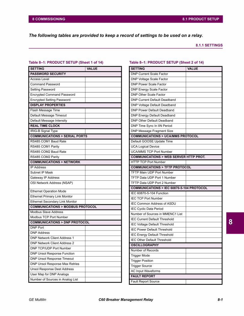
GE Multilin C60 Breaker Management Relay 8-1
8 COMMISSIONING 8.1 PRODUCT SETUP
8
8 COMMISSIONING 8.1 PRODUCT SETUPThe following tables are provided to keep a record of settings to be used on a relay.
8.1.1 SETTINGS
Table 81: PRODUCT SETUP (Sheet 1 of 14)SETTING VALUEPASSWORD SECURITYAccess LevelCommand PasswordSetting PasswordEncrypted Command PasswordEncrypted Setting PasswordDISPLAY PROPERTIESFlash Message TimeDefault Message TimeoutDefault Message IntensityREAL TIME CLOCKIRIG-B Signal TypeCOMMUNICATIONS > SERIAL PORTSRS485 COM1 Baud RateRS485 COM1 ParityRS485 COM2 Baud RateRS485 COM2 ParityCOMMUNICATIONS > NETWORKIP AddressSubnet IP MaskGateway IP AddressOSI Network Address (NSAP)
Ethernet Operation ModeEthernet Primary Link MonitorEthernet Secondary Link MonitorCOMMUNICATIONS > MODBUS PROTOCOLModbus Slave AddressModbus TCP Port NumberCOMMUNICATIONS > DNP PROTOCOLDNP PortDNP AddressDNP Network Client Address 1DNP Network Client Address 2DNP TCP/UDP Port NumberDNP Unsol Response FunctionDNP Unsol Response TimeoutDNP Unsol Response Max RetriesUnsol Response Dest AddressUser Map for DNP AnalogsNumber of Sources in Analog List
DNP Current Scale FactorDNP Voltage Scale FactorDNP Power Scale FactorDNP Energy Scale FactorDNP Other Scale FactorDNP Current Default DeadbandDNP Voltage Default DeadbandDNP Power Default DeadbandDNP Energy Default DeadbandDNP Other Default DeadbandDNP Time Sync In IIN PeriodDNP Message Fragment SizeCOMMUNICATIONS > UCA/MMS PROTOCOLDefault GOOSE Update TimeUCA Logical DeviceUCA/MMS TCP Port NumberCOMMUNICATIONS > WEB SERVER HTTP PROT.HTTP TCP Port NumberCOMMUNICATIONS > TFTP PROTOCOLTFTP Main UDP Port NumberTFTP Data UDP Port 1 NumberTFTP Data UDP Port 2 NumberCOMMUNICATIONS > IEC 60870-5-104 PROTOCOLIEC 60870-5-104 FunctionIEC TCP Port NumberIEC Common Address of ASDUIEC Cyclic Data PeriodNumber of Sources in MMENC1 ListIEC Current Default ThresholdIEC Voltage Default ThresholdIEC Power Default ThresholdIEC Energy Default ThresholdIEC Other Default ThresholdOSCILLOGRAPHYNumber of RecordsTrigger ModeTrigger PositionTrigger SourceAC Input WaveformsFAULT REPORTFault Report Source
Table 81: PRODUCT SETUP (Sheet 2 of 14)SETTING VALUE
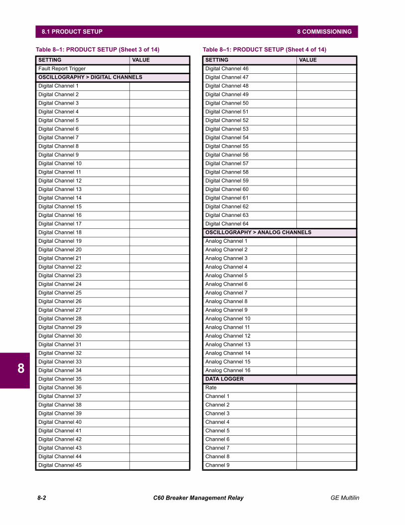
8-2 C60 Breaker Management Relay GE Multilin
8.1 PRODUCT SETUP 8 COMMISSIONING
8
Fault Report TriggerOSCILLOGRAPHY > DIGITAL CHANNELSDigital Channel 1Digital Channel 2Digital Channel 3Digital Channel 4Digital Channel 5Digital Channel 6Digital Channel 7Digital Channel 8Digital Channel 9Digital Channel 10Digital Channel 11Digital Channel 12Digital Channel 13Digital Channel 14Digital Channel 15Digital Channel 16Digital Channel 17Digital Channel 18Digital Channel 19Digital Channel 20Digital Channel 21Digital Channel 22Digital Channel 23Digital Channel 24Digital Channel 25Digital Channel 26Digital Channel 27Digital Channel 28Digital Channel 29Digital Channel 30Digital Channel 31Digital Channel 32Digital Channel 33Digital Channel 34Digital Channel 35Digital Channel 36Digital Channel 37Digital Channel 38Digital Channel 39Digital Channel 40Digital Channel 41Digital Channel 42Digital Channel 43Digital Channel 44Digital Channel 45
Table 81: PRODUCT SETUP (Sheet 3 of 14)SETTING VALUE
Digital Channel 46Digital Channel 47Digital Channel 48Digital Channel 49Digital Channel 50Digital Channel 51Digital Channel 52Digital Channel 53Digital Channel 54Digital Channel 55Digital Channel 56Digital Channel 57Digital Channel 58Digital Channel 59Digital Channel 60Digital Channel 61Digital Channel 62Digital Channel 63Digital Channel 64OSCILLOGRAPHY > ANALOG CHANNELSAnalog Channel 1Analog Channel 2Analog Channel 3Analog Channel 4Analog Channel 5Analog Channel 6Analog Channel 7Analog Channel 8Analog Channel 9Analog Channel 10Analog Channel 11Analog Channel 12Analog Channel 13Analog Channel 14Analog Channel 15Analog Channel 16DATA LOGGERRateChannel 1Channel 2Channel 3Channel 4Channel 5Channel 6Channel 7Channel 8Channel 9
Table 81: PRODUCT SETUP (Sheet 4 of 14)SETTING VALUE
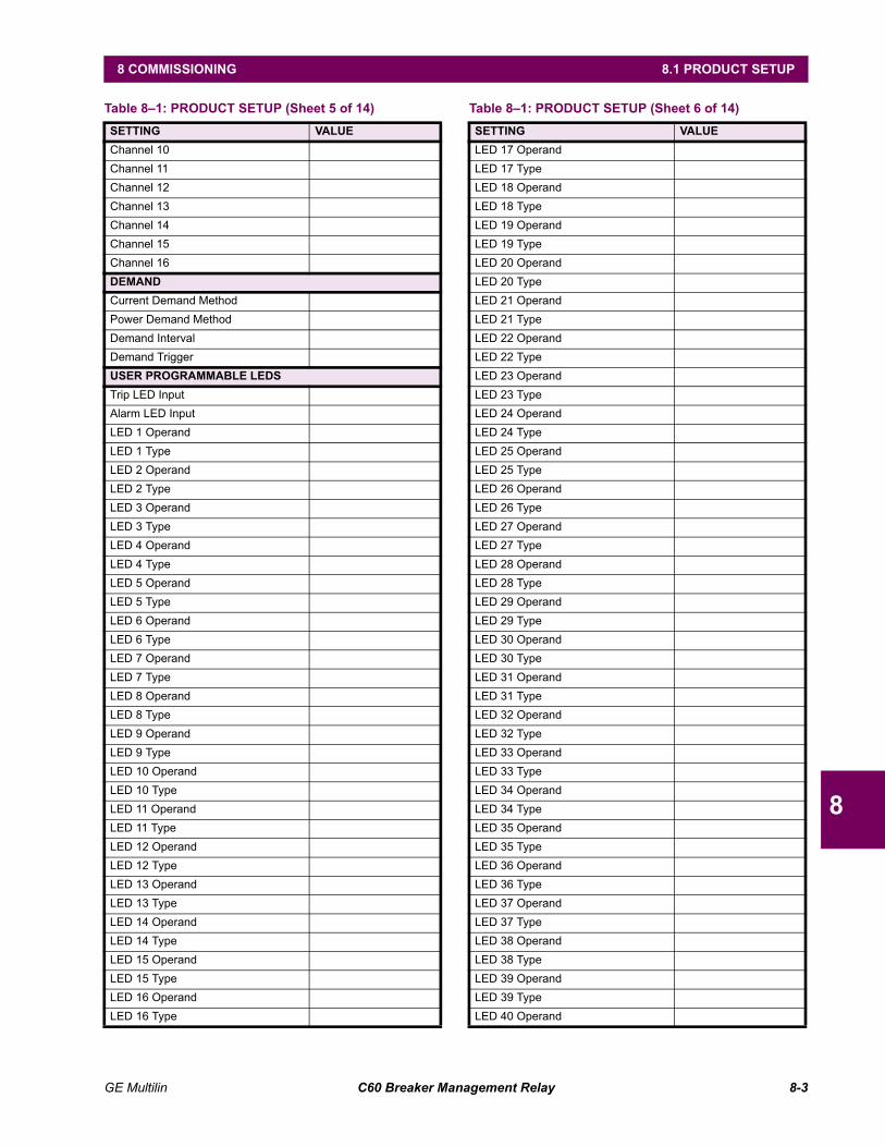
GE Multilin C60 Breaker Management Relay 8-3
8 COMMISSIONING 8.1 PRODUCT SETUP
8
Channel 10Channel 11Channel 12Channel 13Channel 14Channel 15Channel 16DEMANDCurrent Demand MethodPower Demand MethodDemand IntervalDemand TriggerUSER PROGRAMMABLE LEDSTrip LED InputAlarm LED InputLED 1 OperandLED 1 TypeLED 2 OperandLED 2 TypeLED 3 OperandLED 3 TypeLED 4 OperandLED 4 TypeLED 5 OperandLED 5 TypeLED 6 OperandLED 6 TypeLED 7 OperandLED 7 TypeLED 8 OperandLED 8 TypeLED 9 OperandLED 9 TypeLED 10 OperandLED 10 TypeLED 11 OperandLED 11 TypeLED 12 OperandLED 12 TypeLED 13 OperandLED 13 TypeLED 14 OperandLED 14 TypeLED 15 OperandLED 15 TypeLED 16 OperandLED 16 Type
Table 81: PRODUCT SETUP (Sheet 5 of 14)SETTING VALUE
LED 17 OperandLED 17 TypeLED 18 OperandLED 18 TypeLED 19 OperandLED 19 TypeLED 20 OperandLED 20 TypeLED 21 OperandLED 21 TypeLED 22 OperandLED 22 TypeLED 23 OperandLED 23 TypeLED 24 OperandLED 24 TypeLED 25 OperandLED 25 TypeLED 26 OperandLED 26 TypeLED 27 OperandLED 27 TypeLED 28 OperandLED 28 TypeLED 29 OperandLED 29 TypeLED 30 OperandLED 30 TypeLED 31 OperandLED 31 TypeLED 32 OperandLED 32 TypeLED 33 OperandLED 33 TypeLED 34 OperandLED 34 TypeLED 35 OperandLED 35 TypeLED 36 OperandLED 36 TypeLED 37 OperandLED 37 TypeLED 38 OperandLED 38 TypeLED 39 OperandLED 39 TypeLED 40 Operand
Table 81: PRODUCT SETUP (Sheet 6 of 14)SETTING VALUE
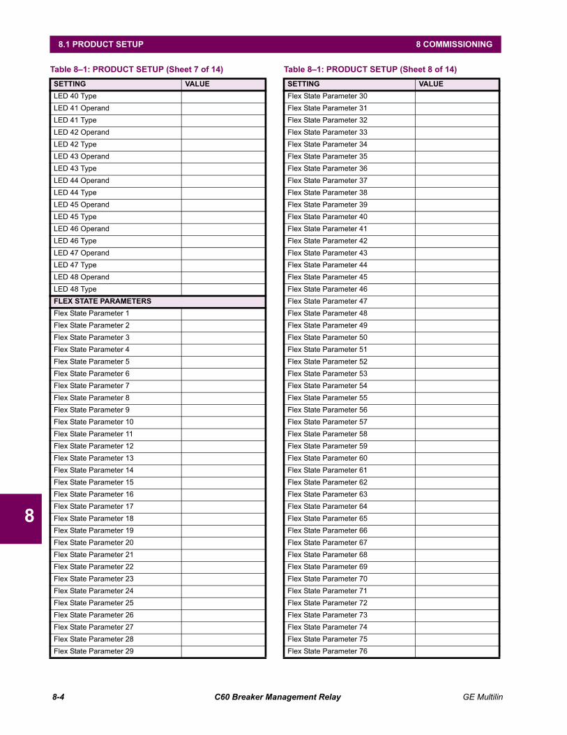
8-4 C60 Breaker Management Relay GE Multilin
8.1 PRODUCT SETUP 8 COMMISSIONING
8
LED 40 TypeLED 41 OperandLED 41 TypeLED 42 OperandLED 42 TypeLED 43 OperandLED 43 TypeLED 44 OperandLED 44 TypeLED 45 OperandLED 45 TypeLED 46 OperandLED 46 TypeLED 47 OperandLED 47 TypeLED 48 OperandLED 48 TypeFLEX STATE PARAMETERSFlex State Parameter 1Flex State Parameter 2Flex State Parameter 3Flex State Parameter 4Flex State Parameter 5Flex State Parameter 6Flex State Parameter 7Flex State Parameter 8Flex State Parameter 9Flex State Parameter 10Flex State Parameter 11Flex State Parameter 12Flex State Parameter 13Flex State Parameter 14Flex State Parameter 15Flex State Parameter 16Flex State Parameter 17Flex State Parameter 18Flex State Parameter 19Flex State Parameter 20Flex State Parameter 21Flex State Parameter 22Flex State Parameter 23Flex State Parameter 24Flex State Parameter 25Flex State Parameter 26Flex State Parameter 27Flex State Parameter 28Flex State Parameter 29
Table 81: PRODUCT SETUP (Sheet 7 of 14)SETTING VALUE
Flex State Parameter 30Flex State Parameter 31Flex State Parameter 32Flex State Parameter 33Flex State Parameter 34Flex State Parameter 35Flex State Parameter 36Flex State Parameter 37Flex State Parameter 38Flex State Parameter 39Flex State Parameter 40Flex State Parameter 41Flex State Parameter 42Flex State Parameter 43Flex State Parameter 44Flex State Parameter 45Flex State Parameter 46Flex State Parameter 47Flex State Parameter 48Flex State Parameter 49Flex State Parameter 50Flex State Parameter 51Flex State Parameter 52Flex State Parameter 53Flex State Parameter 54Flex State Parameter 55Flex State Parameter 56Flex State Parameter 57Flex State Parameter 58Flex State Parameter 59Flex State Parameter 60Flex State Parameter 61Flex State Parameter 62Flex State Parameter 63Flex State Parameter 64Flex State Parameter 65Flex State Parameter 66Flex State Parameter 67Flex State Parameter 68Flex State Parameter 69Flex State Parameter 70Flex State Parameter 71Flex State Parameter 72Flex State Parameter 73Flex State Parameter 74Flex State Parameter 75Flex State Parameter 76
Table 81: PRODUCT SETUP (Sheet 8 of 14)SETTING VALUE
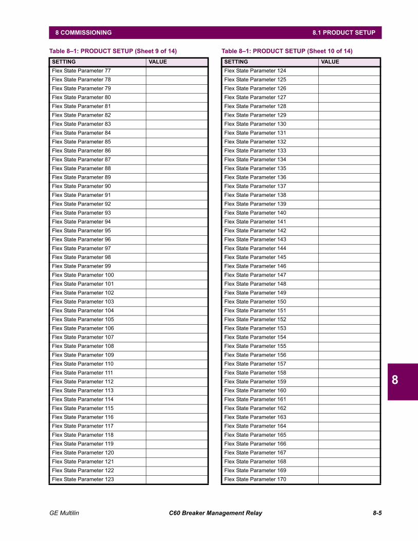
GE Multilin C60 Breaker Management Relay 8-5
8 COMMISSIONING 8.1 PRODUCT SETUP
8
Flex State Parameter 77Flex State Parameter 78Flex State Parameter 79Flex State Parameter 80Flex State Parameter 81Flex State Parameter 82Flex State Parameter 83Flex State Parameter 84Flex State Parameter 85Flex State Parameter 86Flex State Parameter 87Flex State Parameter 88Flex State Parameter 89Flex State Parameter 90Flex State Parameter 91Flex State Parameter 92Flex State Parameter 93Flex State Parameter 94Flex State Parameter 95Flex State Parameter 96Flex State Parameter 97Flex State Parameter 98Flex State Parameter 99Flex State Parameter 100Flex State Parameter 101Flex State Parameter 102Flex State Parameter 103Flex State Parameter 104Flex State Parameter 105Flex State Parameter 106Flex State Parameter 107Flex State Parameter 108Flex State Parameter 109Flex State Parameter 110Flex State Parameter 111Flex State Parameter 112Flex State Parameter 113Flex State Parameter 114Flex State Parameter 115Flex State Parameter 116Flex State Parameter 117Flex State Parameter 118Flex State Parameter 119Flex State Parameter 120Flex State Parameter 121Flex State Parameter 122Flex State Parameter 123
Table 81: PRODUCT SETUP (Sheet 9 of 14)SETTING VALUE
Flex State Parameter 124Flex State Parameter 125Flex State Parameter 126Flex State Parameter 127Flex State Parameter 128Flex State Parameter 129Flex State Parameter 130Flex State Parameter 131Flex State Parameter 132Flex State Parameter 133Flex State Parameter 134Flex State Parameter 135Flex State Parameter 136Flex State Parameter 137Flex State Parameter 138Flex State Parameter 139Flex State Parameter 140Flex State Parameter 141Flex State Parameter 142Flex State Parameter 143Flex State Parameter 144Flex State Parameter 145Flex State Parameter 146Flex State Parameter 147Flex State Parameter 148Flex State Parameter 149Flex State Parameter 150Flex State Parameter 151Flex State Parameter 152Flex State Parameter 153Flex State Parameter 154Flex State Parameter 155Flex State Parameter 156Flex State Parameter 157Flex State Parameter 158Flex State Parameter 159Flex State Parameter 160Flex State Parameter 161Flex State Parameter 162Flex State Parameter 163Flex State Parameter 164Flex State Parameter 165Flex State Parameter 166Flex State Parameter 167Flex State Parameter 168Flex State Parameter 169Flex State Parameter 170
Table 81: PRODUCT SETUP (Sheet 10 of 14)SETTING VALUE

8-6 C60 Breaker Management Relay GE Multilin
8.1 PRODUCT SETUP 8 COMMISSIONING
8
Flex State Parameter 171Flex State Parameter 172Flex State Parameter 173Flex State Parameter 174Flex State Parameter 175Flex State Parameter 176Flex State Parameter 177Flex State Parameter 178Flex State Parameter 179Flex State Parameter 180Flex State Parameter 181Flex State Parameter 182Flex State Parameter 183Flex State Parameter 184Flex State Parameter 185Flex State Parameter 186Flex State Parameter 187Flex State Parameter 188Flex State Parameter 189Flex State Parameter 190Flex State Parameter 191Flex State Parameter 192Flex State Parameter 193Flex State Parameter 194Flex State Parameter 195Flex State Parameter 196Flex State Parameter 197Flex State Parameter 198Flex State Parameter 199Flex State Parameter 200Flex State Parameter 201Flex State Parameter 202Flex State Parameter 203Flex State Parameter 204Flex State Parameter 205Flex State Parameter 206Flex State Parameter 207Flex State Parameter 208Flex State Parameter 209Flex State Parameter 210Flex State Parameter 211Flex State Parameter 212Flex State Parameter 213Flex State Parameter 214Flex State Parameter 215Flex State Parameter 216Flex State Parameter 217
Table 81: PRODUCT SETUP (Sheet 11 of 14)SETTING VALUE
Flex State Parameter 218Flex State Parameter 219Flex State Parameter 220Flex State Parameter 221Flex State Parameter 222Flex State Parameter 223Flex State Parameter 224Flex State Parameter 225Flex State Parameter 226Flex State Parameter 227Flex State Parameter 228Flex State Parameter 229Flex State Parameter 230Flex State Parameter 231Flex State Parameter 232Flex State Parameter 233Flex State Parameter 234Flex State Parameter 235Flex State Parameter 236Flex State Parameter 237Flex State Parameter 238Flex State Parameter 239Flex State Parameter 240Flex State Parameter 241Flex State Parameter 242Flex State Parameter 243Flex State Parameter 244Flex State Parameter 245Flex State Parameter 246Flex State Parameter 247Flex State Parameter 248Flex State Parameter 249Flex State Parameter 250Flex State Parameter 251Flex State Parameter 252Flex State Parameter 253Flex State Parameter 254Flex State Parameter 255Flex State Parameter 256USER DISPLAY 1Disp 1 Top LineDisp 1 Bottom LineDisp 1 Item 1Disp 1 Item 2Disp 1 Item 3Disp 1 Item 4Disp 1 Item 5
Table 81: PRODUCT SETUP (Sheet 12 of 14)SETTING VALUE
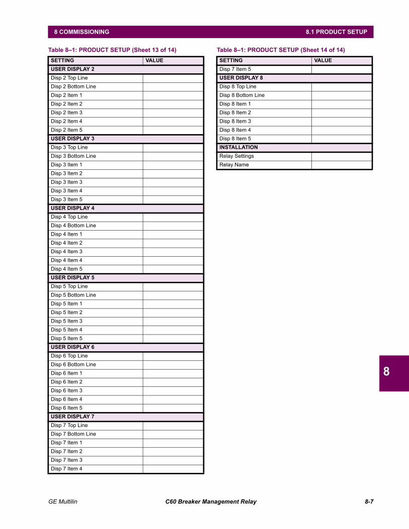
GE Multilin C60 Breaker Management Relay 8-7
8 COMMISSIONING 8.1 PRODUCT SETUP
8
USER DISPLAY 2Disp 2 Top LineDisp 2 Bottom LineDisp 2 Item 1Disp 2 Item 2Disp 2 Item 3Disp 2 Item 4Disp 2 Item 5USER DISPLAY 3Disp 3 Top LineDisp 3 Bottom LineDisp 3 Item 1Disp 3 Item 2Disp 3 Item 3Disp 3 Item 4Disp 3 Item 5USER DISPLAY 4Disp 4 Top LineDisp 4 Bottom LineDisp 4 Item 1Disp 4 Item 2Disp 4 Item 3Disp 4 Item 4Disp 4 Item 5USER DISPLAY 5Disp 5 Top LineDisp 5 Bottom LineDisp 5 Item 1Disp 5 Item 2Disp 5 Item 3Disp 5 Item 4Disp 5 Item 5USER DISPLAY 6Disp 6 Top LineDisp 6 Bottom LineDisp 6 Item 1Disp 6 Item 2Disp 6 Item 3Disp 6 Item 4Disp 6 Item 5USER DISPLAY 7Disp 7 Top LineDisp 7 Bottom LineDisp 7 Item 1Disp 7 Item 2Disp 7 Item 3Disp 7 Item 4
Table 81: PRODUCT SETUP (Sheet 13 of 14)SETTING VALUE
Disp 7 Item 5USER DISPLAY 8Disp 8 Top LineDisp 8 Bottom LineDisp 8 Item 1Disp 8 Item 2Disp 8 Item 3Disp 8 Item 4Disp 8 Item 5INSTALLATIONRelay SettingsRelay Name
Table 81: PRODUCT SETUP (Sheet 14 of 14)SETTING VALUE
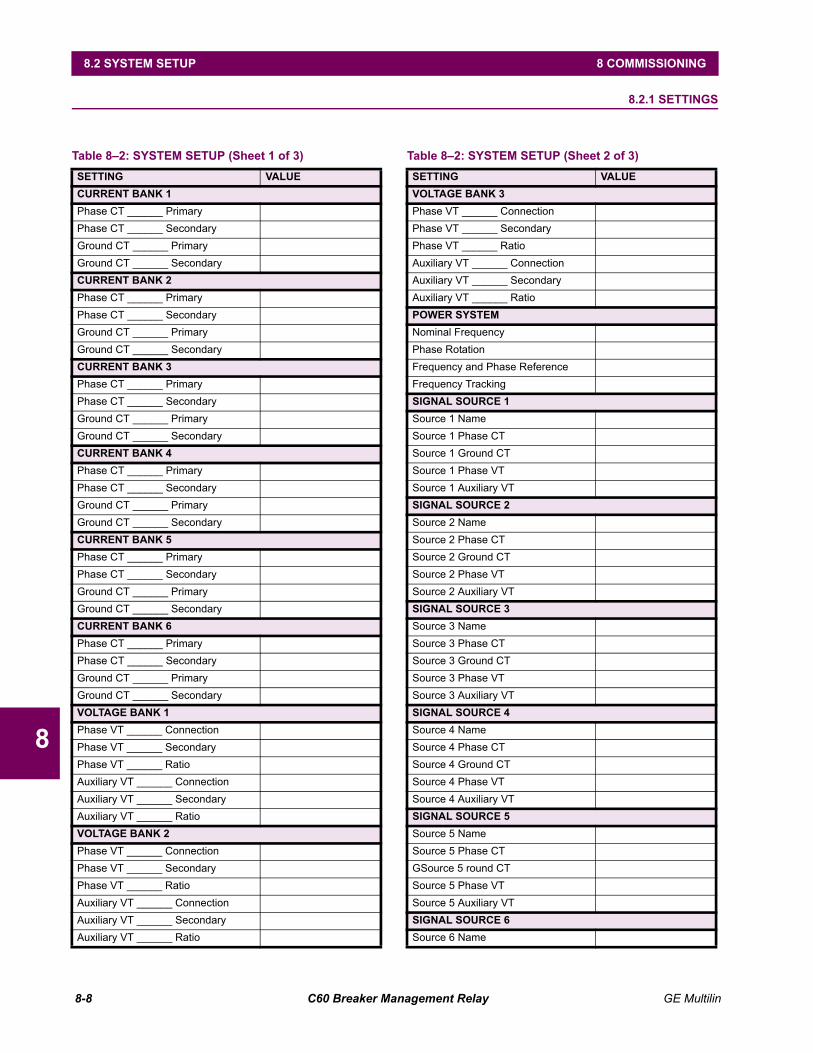
8-8 C60 Breaker Management Relay GE Multilin
8.2 SYSTEM SETUP 8 COMMISSIONING
8
8.2 SYSTEM SETUP 8.2.1 SETTINGS
Table 82: SYSTEM SETUP (Sheet 1 of 3)SETTING VALUECURRENT BANK 1Phase CT ______ PrimaryPhase CT ______ SecondaryGround CT ______ PrimaryGround CT ______ SecondaryCURRENT BANK 2Phase CT ______ PrimaryPhase CT ______ SecondaryGround CT ______ PrimaryGround CT ______ SecondaryCURRENT BANK 3Phase CT ______ PrimaryPhase CT ______ SecondaryGround CT ______ PrimaryGround CT ______ SecondaryCURRENT BANK 4Phase CT ______ PrimaryPhase CT ______ SecondaryGround CT ______ PrimaryGround CT ______ SecondaryCURRENT BANK 5Phase CT ______ PrimaryPhase CT ______ SecondaryGround CT ______ PrimaryGround CT ______ SecondaryCURRENT BANK 6Phase CT ______ PrimaryPhase CT ______ SecondaryGround CT ______ PrimaryGround CT ______ SecondaryVOLTAGE BANK 1Phase VT ______ ConnectionPhase VT ______ SecondaryPhase VT ______ RatioAuxiliary VT ______ ConnectionAuxiliary VT ______ SecondaryAuxiliary VT ______ RatioVOLTAGE BANK 2Phase VT ______ ConnectionPhase VT ______ SecondaryPhase VT ______ RatioAuxiliary VT ______ ConnectionAuxiliary VT ______ SecondaryAuxiliary VT ______ Ratio
VOLTAGE BANK 3Phase VT ______ ConnectionPhase VT ______ SecondaryPhase VT ______ RatioAuxiliary VT ______ ConnectionAuxiliary VT ______ SecondaryAuxiliary VT ______ RatioPOWER SYSTEMNominal FrequencyPhase RotationFrequency and Phase ReferenceFrequency TrackingSIGNAL SOURCE 1Source 1 NameSource 1 Phase CTSource 1 Ground CTSource 1 Phase VTSource 1 Auxiliary VTSIGNAL SOURCE 2Source 2 NameSource 2 Phase CTSource 2 Ground CTSource 2 Phase VTSource 2 Auxiliary VTSIGNAL SOURCE 3Source 3 NameSource 3 Phase CTSource 3 Ground CTSource 3 Phase VTSource 3 Auxiliary VTSIGNAL SOURCE 4Source 4 NameSource 4 Phase CTSource 4 Ground CTSource 4 Phase VTSource 4 Auxiliary VTSIGNAL SOURCE 5Source 5 NameSource 5 Phase CTGSource 5 round CTSource 5 Phase VTSource 5 Auxiliary VTSIGNAL SOURCE 6Source 6 Name
Table 82: SYSTEM SETUP (Sheet 2 of 3)SETTING VALUE
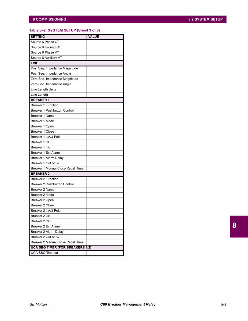
GE Multilin C60 Breaker Management Relay 8-9
8 COMMISSIONING 8.2 SYSTEM SETUP
8
Source 6 Phase CTSource 6 Ground CTSource 6 Phase VTSource 6 Auxiliary VTLINEPos. Seq. Impedance MagnitudePos. Seq. Impedance AngleZero Seq. Impedance MagnitudeZero Seq. Impedance AngleLine Length UnitsLine LengthBREAKER 1Breaker 1 FunctionBreaker 1 Pushbutton ControlBreaker 1 NameBreaker 1 ModeBreaker 1 OpenBreaker 1 CloseBreaker 1 ΦA/3-PoleBreaker 1 ΦBBreaker 1 ΦCBreaker 1 Ext AlarmBreaker 1 Alarm DelayBreaker 1 Out of SvBreaker 1 Manual Close Recall TimeBREAKER 2Breaker 2 FunctionBreaker 2 Pushbutton ControlBreaker 2 NameBreaker 2 ModeBreaker 2 OpenBreaker 2 CloseBreaker 2 ΦA/3-PoleBreaker 2 ΦBBreaker 2 ΦCBreaker 2 Ext AlarmBreaker 2 Alarm DelayBreaker 2 Out of SvBreaker 2 Manual Close Recall TimeUCA SBO TIMER (FOR BREAKERS 1/2)UCA SBO Timeout
Table 82: SYSTEM SETUP (Sheet 3 of 3)SETTING VALUE
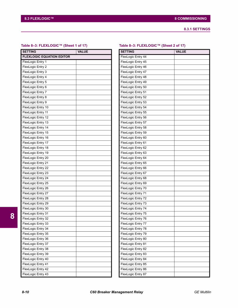
8-10 C60 Breaker Management Relay GE Multilin
8.3 FLEXLOGIC 8 COMMISSIONING
8
8.3 FLEXLOGIC 8.3.1 SETTINGS
Table 83: FLEXLOGIC (Sheet 1 of 17)SETTING VALUEFLEXLOGIC EQUATION EDITORFlexLogic Entry 1FlexLogic Entry 2FlexLogic Entry 3FlexLogic Entry 4FlexLogic Entry 5FlexLogic Entry 6FlexLogic Entry 7FlexLogic Entry 8FlexLogic Entry 9FlexLogic Entry 10FlexLogic Entry 11FlexLogic Entry 12FlexLogic Entry 13FlexLogic Entry 14FlexLogic Entry 15FlexLogic Entry 16FlexLogic Entry 17FlexLogic Entry 18FlexLogic Entry 19FlexLogic Entry 20FlexLogic Entry 21FlexLogic Entry 22FlexLogic Entry 23FlexLogic Entry 24FlexLogic Entry 25FlexLogic Entry 26FlexLogic Entry 27FlexLogic Entry 28FlexLogic Entry 29FlexLogic Entry 30FlexLogic Entry 31FlexLogic Entry 32FlexLogic Entry 33FlexLogic Entry 34FlexLogic Entry 35FlexLogic Entry 36FlexLogic Entry 37FlexLogic Entry 38FlexLogic Entry 39FlexLogic Entry 40FlexLogic Entry 41FlexLogic Entry 42FlexLogic Entry 43
FlexLogic Entry 44FlexLogic Entry 45FlexLogic Entry 46FlexLogic Entry 47FlexLogic Entry 48FlexLogic Entry 49FlexLogic Entry 50FlexLogic Entry 51FlexLogic Entry 52FlexLogic Entry 53FlexLogic Entry 54FlexLogic Entry 55FlexLogic Entry 56FlexLogic Entry 57FlexLogic Entry 58FlexLogic Entry 59FlexLogic Entry 60FlexLogic Entry 61FlexLogic Entry 62FlexLogic Entry 63FlexLogic Entry 64FlexLogic Entry 65FlexLogic Entry 66FlexLogic Entry 67FlexLogic Entry 68FlexLogic Entry 69FlexLogic Entry 70FlexLogic Entry 71FlexLogic Entry 72FlexLogic Entry 73FlexLogic Entry 74FlexLogic Entry 75FlexLogic Entry 76FlexLogic Entry 77FlexLogic Entry 78FlexLogic Entry 79FlexLogic Entry 80FlexLogic Entry 81FlexLogic Entry 82FlexLogic Entry 83FlexLogic Entry 84FlexLogic Entry 85FlexLogic Entry 86FlexLogic Entry 87
Table 83: FLEXLOGIC (Sheet 2 of 17)SETTING VALUE

GE Multilin C60 Breaker Management Relay 8-11
8 COMMISSIONING 8.3 FLEXLOGIC
8
FlexLogic Entry 88FlexLogic Entry 89FlexLogic Entry 90FlexLogic Entry 91FlexLogic Entry 92FlexLogic Entry 93FlexLogic Entry 94FlexLogic Entry 95FlexLogic Entry 96FlexLogic Entry 97FlexLogic Entry 98FlexLogic Entry 99FlexLogic Entry 100FlexLogic Entry 101FlexLogic Entry 102FlexLogic Entry 103FlexLogic Entry 104FlexLogic Entry 105FlexLogic Entry 106FlexLogic Entry 107FlexLogic Entry 108FlexLogic Entry 109FlexLogic Entry 110FlexLogic Entry 111FlexLogic Entry 112FlexLogic Entry 113FlexLogic Entry 114FlexLogic Entry 115FlexLogic Entry 116FlexLogic Entry 117FlexLogic Entry 118FlexLogic Entry 119FlexLogic Entry 120FlexLogic Entry 121FlexLogic Entry 122FlexLogic Entry 123FlexLogic Entry 124FlexLogic Entry 125FlexLogic Entry 126FlexLogic Entry 127FlexLogic Entry 128FlexLogic Entry 129FlexLogic Entry 130FlexLogic Entry 131FlexLogic Entry 132FlexLogic Entry 133FlexLogic Entry 134
Table 83: FLEXLOGIC (Sheet 3 of 17)SETTING VALUE
FlexLogic Entry 135FlexLogic Entry 136FlexLogic Entry 137FlexLogic Entry 138FlexLogic Entry 139FlexLogic Entry 140FlexLogic Entry 141FlexLogic Entry 142FlexLogic Entry 143FlexLogic Entry 144FlexLogic Entry 145FlexLogic Entry 146FlexLogic Entry 147FlexLogic Entry 148FlexLogic Entry 149FlexLogic Entry 150FlexLogic Entry 151FlexLogic Entry 152FlexLogic Entry 153FlexLogic Entry 154FlexLogic Entry 155FlexLogic Entry 156FlexLogic Entry 157FlexLogic Entry 158FlexLogic Entry 159FlexLogic Entry 160FlexLogic Entry 161FlexLogic Entry 162FlexLogic Entry 163FlexLogic Entry 164FlexLogic Entry 165FlexLogic Entry 166FlexLogic Entry 167FlexLogic Entry 168FlexLogic Entry 169FlexLogic Entry 170FlexLogic Entry 171FlexLogic Entry 172FlexLogic Entry 173FlexLogic Entry 174FlexLogic Entry 175FlexLogic Entry 176FlexLogic Entry 177FlexLogic Entry 178FlexLogic Entry 179FlexLogic Entry 180FlexLogic Entry 181
Table 83: FLEXLOGIC (Sheet 4 of 17)SETTING VALUE
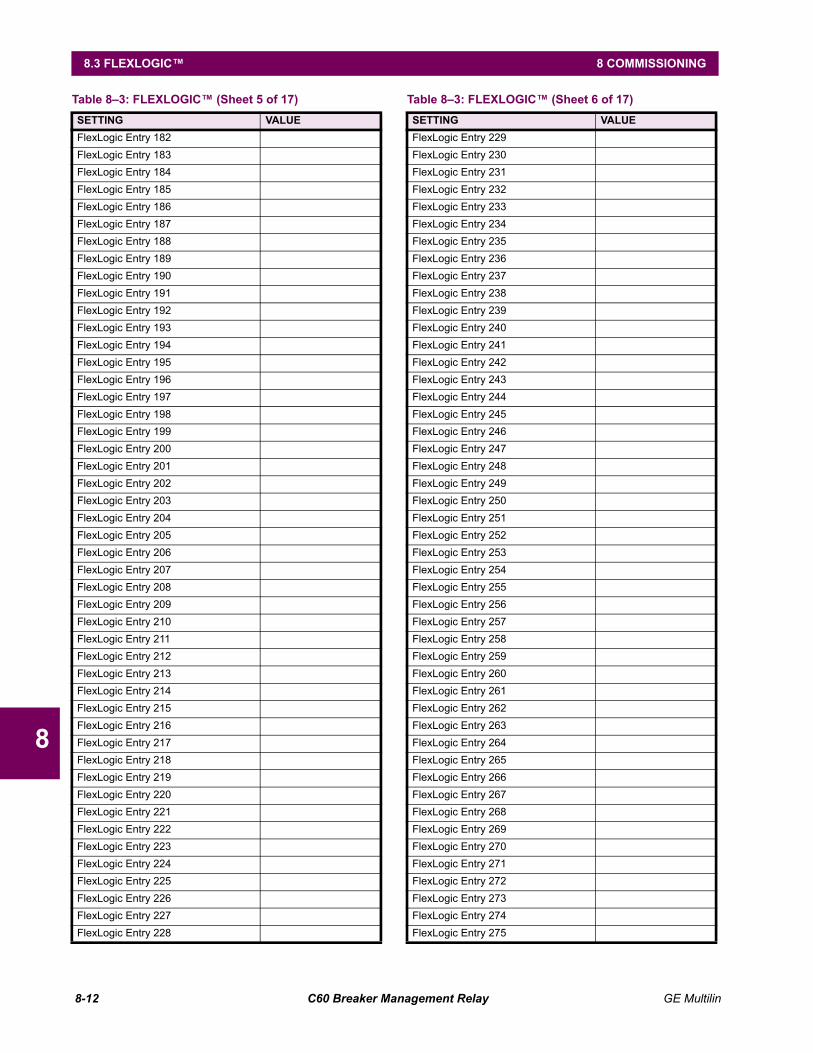
8-12 C60 Breaker Management Relay GE Multilin
8.3 FLEXLOGIC 8 COMMISSIONING
8
FlexLogic Entry 182FlexLogic Entry 183FlexLogic Entry 184FlexLogic Entry 185FlexLogic Entry 186FlexLogic Entry 187FlexLogic Entry 188FlexLogic Entry 189FlexLogic Entry 190FlexLogic Entry 191FlexLogic Entry 192FlexLogic Entry 193FlexLogic Entry 194FlexLogic Entry 195FlexLogic Entry 196FlexLogic Entry 197FlexLogic Entry 198FlexLogic Entry 199FlexLogic Entry 200FlexLogic Entry 201FlexLogic Entry 202FlexLogic Entry 203FlexLogic Entry 204FlexLogic Entry 205FlexLogic Entry 206FlexLogic Entry 207FlexLogic Entry 208FlexLogic Entry 209FlexLogic Entry 210FlexLogic Entry 211FlexLogic Entry 212FlexLogic Entry 213FlexLogic Entry 214FlexLogic Entry 215FlexLogic Entry 216FlexLogic Entry 217FlexLogic Entry 218FlexLogic Entry 219FlexLogic Entry 220FlexLogic Entry 221FlexLogic Entry 222FlexLogic Entry 223FlexLogic Entry 224FlexLogic Entry 225FlexLogic Entry 226FlexLogic Entry 227FlexLogic Entry 228
Table 83: FLEXLOGIC (Sheet 5 of 17)SETTING VALUE
FlexLogic Entry 229FlexLogic Entry 230FlexLogic Entry 231FlexLogic Entry 232FlexLogic Entry 233FlexLogic Entry 234FlexLogic Entry 235FlexLogic Entry 236FlexLogic Entry 237FlexLogic Entry 238FlexLogic Entry 239FlexLogic Entry 240FlexLogic Entry 241FlexLogic Entry 242FlexLogic Entry 243FlexLogic Entry 244FlexLogic Entry 245FlexLogic Entry 246FlexLogic Entry 247FlexLogic Entry 248FlexLogic Entry 249FlexLogic Entry 250FlexLogic Entry 251FlexLogic Entry 252FlexLogic Entry 253FlexLogic Entry 254FlexLogic Entry 255FlexLogic Entry 256FlexLogic Entry 257FlexLogic Entry 258FlexLogic Entry 259FlexLogic Entry 260FlexLogic Entry 261FlexLogic Entry 262FlexLogic Entry 263FlexLogic Entry 264FlexLogic Entry 265FlexLogic Entry 266FlexLogic Entry 267FlexLogic Entry 268FlexLogic Entry 269FlexLogic Entry 270FlexLogic Entry 271FlexLogic Entry 272FlexLogic Entry 273FlexLogic Entry 274FlexLogic Entry 275
Table 83: FLEXLOGIC (Sheet 6 of 17)SETTING VALUE
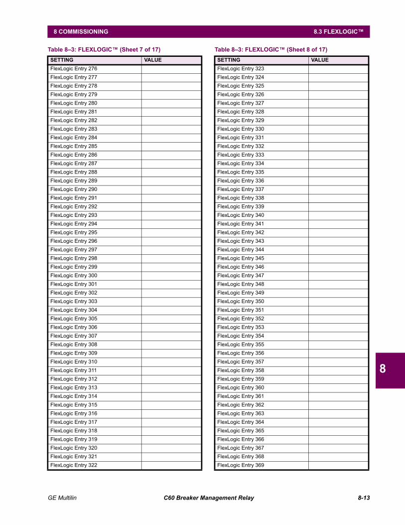
GE Multilin C60 Breaker Management Relay 8-13
8 COMMISSIONING 8.3 FLEXLOGIC
8
FlexLogic Entry 276FlexLogic Entry 277FlexLogic Entry 278FlexLogic Entry 279FlexLogic Entry 280FlexLogic Entry 281FlexLogic Entry 282FlexLogic Entry 283FlexLogic Entry 284FlexLogic Entry 285FlexLogic Entry 286FlexLogic Entry 287FlexLogic Entry 288FlexLogic Entry 289FlexLogic Entry 290FlexLogic Entry 291FlexLogic Entry 292FlexLogic Entry 293FlexLogic Entry 294FlexLogic Entry 295FlexLogic Entry 296FlexLogic Entry 297FlexLogic Entry 298FlexLogic Entry 299FlexLogic Entry 300FlexLogic Entry 301FlexLogic Entry 302FlexLogic Entry 303FlexLogic Entry 304FlexLogic Entry 305FlexLogic Entry 306FlexLogic Entry 307FlexLogic Entry 308FlexLogic Entry 309FlexLogic Entry 310FlexLogic Entry 311FlexLogic Entry 312FlexLogic Entry 313FlexLogic Entry 314FlexLogic Entry 315FlexLogic Entry 316FlexLogic Entry 317FlexLogic Entry 318FlexLogic Entry 319FlexLogic Entry 320FlexLogic Entry 321FlexLogic Entry 322
Table 83: FLEXLOGIC (Sheet 7 of 17)SETTING VALUE
FlexLogic Entry 323FlexLogic Entry 324FlexLogic Entry 325FlexLogic Entry 326FlexLogic Entry 327FlexLogic Entry 328FlexLogic Entry 329FlexLogic Entry 330FlexLogic Entry 331FlexLogic Entry 332FlexLogic Entry 333FlexLogic Entry 334FlexLogic Entry 335FlexLogic Entry 336FlexLogic Entry 337FlexLogic Entry 338FlexLogic Entry 339FlexLogic Entry 340FlexLogic Entry 341FlexLogic Entry 342FlexLogic Entry 343FlexLogic Entry 344FlexLogic Entry 345FlexLogic Entry 346FlexLogic Entry 347FlexLogic Entry 348FlexLogic Entry 349FlexLogic Entry 350FlexLogic Entry 351FlexLogic Entry 352FlexLogic Entry 353FlexLogic Entry 354FlexLogic Entry 355FlexLogic Entry 356FlexLogic Entry 357FlexLogic Entry 358FlexLogic Entry 359FlexLogic Entry 360FlexLogic Entry 361FlexLogic Entry 362FlexLogic Entry 363FlexLogic Entry 364FlexLogic Entry 365FlexLogic Entry 366FlexLogic Entry 367FlexLogic Entry 368FlexLogic Entry 369
Table 83: FLEXLOGIC (Sheet 8 of 17)SETTING VALUE

8-14 C60 Breaker Management Relay GE Multilin
8.3 FLEXLOGIC 8 COMMISSIONING
8
FlexLogic Entry 370FlexLogic Entry 371FlexLogic Entry 372FlexLogic Entry 373FlexLogic Entry 374FlexLogic Entry 375FlexLogic Entry 376FlexLogic Entry 377FlexLogic Entry 378FlexLogic Entry 379FlexLogic Entry 380FlexLogic Entry 381FlexLogic Entry 382FlexLogic Entry 383FlexLogic Entry 384FlexLogic Entry 385FlexLogic Entry 386FlexLogic Entry 387FlexLogic Entry 388FlexLogic Entry 389FlexLogic Entry 390FlexLogic Entry 391FlexLogic Entry 392FlexLogic Entry 393FlexLogic Entry 394FlexLogic Entry 395FlexLogic Entry 396FlexLogic Entry 397FlexLogic Entry 398FlexLogic Entry 399FlexLogic Entry 400FlexLogic Entry 401FlexLogic Entry 402FlexLogic Entry 403FlexLogic Entry 404FlexLogic Entry 405FlexLogic Entry 406FlexLogic Entry 407FlexLogic Entry 408FlexLogic Entry 409FlexLogic Entry 410FlexLogic Entry 411FlexLogic Entry 412FlexLogic Entry 413FlexLogic Entry 414FlexLogic Entry 415FlexLogic Entry 416
Table 83: FLEXLOGIC (Sheet 9 of 17)SETTING VALUE
FlexLogic Entry 417FlexLogic Entry 418FlexLogic Entry 419FlexLogic Entry 420FlexLogic Entry 421FlexLogic Entry 422FlexLogic Entry 423FlexLogic Entry 424FlexLogic Entry 425FlexLogic Entry 426FlexLogic Entry 427FlexLogic Entry 428FlexLogic Entry 429FlexLogic Entry 430FlexLogic Entry 431FlexLogic Entry 432FlexLogic Entry 433FlexLogic Entry 434FlexLogic Entry 435FlexLogic Entry 436FlexLogic Entry 437FlexLogic Entry 438FlexLogic Entry 439FlexLogic Entry 440FlexLogic Entry 441FlexLogic Entry 442FlexLogic Entry 443FlexLogic Entry 444FlexLogic Entry 445FlexLogic Entry 446FlexLogic Entry 447FlexLogic Entry 448FlexLogic Entry 449FlexLogic Entry 450FlexLogic Entry 451FlexLogic Entry 452FlexLogic Entry 453FlexLogic Entry 454FlexLogic Entry 455FlexLogic Entry 456FlexLogic Entry 457FlexLogic Entry 458FlexLogic Entry 459FlexLogic Entry 460FlexLogic Entry 461FlexLogic Entry 462FlexLogic Entry 463
Table 83: FLEXLOGIC (Sheet 10 of 17)SETTING VALUE
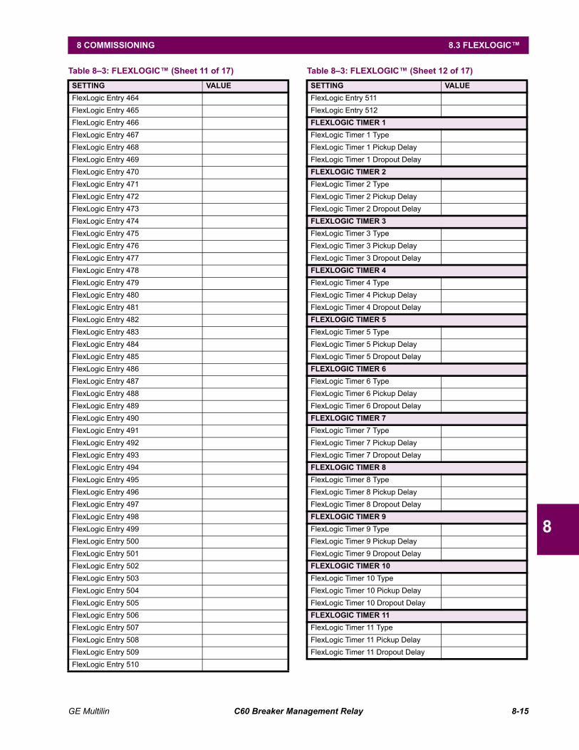
GE Multilin C60 Breaker Management Relay 8-15
8 COMMISSIONING 8.3 FLEXLOGIC
8
FlexLogic Entry 464FlexLogic Entry 465FlexLogic Entry 466FlexLogic Entry 467FlexLogic Entry 468FlexLogic Entry 469FlexLogic Entry 470FlexLogic Entry 471FlexLogic Entry 472FlexLogic Entry 473FlexLogic Entry 474FlexLogic Entry 475FlexLogic Entry 476FlexLogic Entry 477FlexLogic Entry 478FlexLogic Entry 479FlexLogic Entry 480FlexLogic Entry 481FlexLogic Entry 482FlexLogic Entry 483FlexLogic Entry 484FlexLogic Entry 485FlexLogic Entry 486FlexLogic Entry 487FlexLogic Entry 488FlexLogic Entry 489FlexLogic Entry 490FlexLogic Entry 491FlexLogic Entry 492FlexLogic Entry 493FlexLogic Entry 494FlexLogic Entry 495FlexLogic Entry 496FlexLogic Entry 497FlexLogic Entry 498FlexLogic Entry 499FlexLogic Entry 500FlexLogic Entry 501FlexLogic Entry 502FlexLogic Entry 503FlexLogic Entry 504FlexLogic Entry 505FlexLogic Entry 506FlexLogic Entry 507FlexLogic Entry 508FlexLogic Entry 509FlexLogic Entry 510
Table 83: FLEXLOGIC (Sheet 11 of 17)SETTING VALUE
FlexLogic Entry 511FlexLogic Entry 512FLEXLOGIC TIMER 1FlexLogic Timer 1 TypeFlexLogic Timer 1 Pickup DelayFlexLogic Timer 1 Dropout DelayFLEXLOGIC TIMER 2FlexLogic Timer 2 TypeFlexLogic Timer 2 Pickup DelayFlexLogic Timer 2 Dropout DelayFLEXLOGIC TIMER 3FlexLogic Timer 3 TypeFlexLogic Timer 3 Pickup DelayFlexLogic Timer 3 Dropout DelayFLEXLOGIC TIMER 4FlexLogic Timer 4 TypeFlexLogic Timer 4 Pickup DelayFlexLogic Timer 4 Dropout DelayFLEXLOGIC TIMER 5FlexLogic Timer 5 TypeFlexLogic Timer 5 Pickup DelayFlexLogic Timer 5 Dropout DelayFLEXLOGIC TIMER 6FlexLogic Timer 6 TypeFlexLogic Timer 6 Pickup DelayFlexLogic Timer 6 Dropout DelayFLEXLOGIC TIMER 7FlexLogic Timer 7 TypeFlexLogic Timer 7 Pickup DelayFlexLogic Timer 7 Dropout DelayFLEXLOGIC TIMER 8FlexLogic Timer 8 TypeFlexLogic Timer 8 Pickup DelayFlexLogic Timer 8 Dropout DelayFLEXLOGIC TIMER 9FlexLogic Timer 9 TypeFlexLogic Timer 9 Pickup DelayFlexLogic Timer 9 Dropout DelayFLEXLOGIC TIMER 10FlexLogic Timer 10 TypeFlexLogic Timer 10 Pickup DelayFlexLogic Timer 10 Dropout DelayFLEXLOGIC TIMER 11FlexLogic Timer 11 TypeFlexLogic Timer 11 Pickup DelayFlexLogic Timer 11 Dropout Delay
Table 83: FLEXLOGIC (Sheet 12 of 17)SETTING VALUE
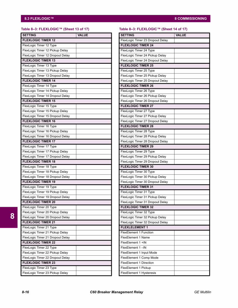
8-16 C60 Breaker Management Relay GE Multilin
8.3 FLEXLOGIC 8 COMMISSIONING
8
FLEXLOGIC TIMER 12FlexLogic Timer 12 TypeFlexLogic Timer 12 Pickup DelayFlexLogic Timer 12 Dropout DelayFLEXLOGIC TIMER 13FlexLogic Timer 13 TypeFlexLogic Timer 13 Pickup DelayFlexLogic Timer 13 Dropout DelayFLEXLOGIC TIMER 14FlexLogic Timer 14 TypeFlexLogic Timer 14 Pickup DelayFlexLogic Timer 14 Dropout DelayFLEXLOGIC TIMER 15FlexLogic Timer 15 TypeFlexLogic Timer 15 Pickup DelayFlexLogic Timer 15 Dropout DelayFLEXLOGIC TIMER 16FlexLogic Timer 16 TypeFlexLogic Timer 16 Pickup DelayFlexLogic Timer 16 Dropout DelayFLEXLOGIC TIMER 17FlexLogic Timer 17 TypeFlexLogic Timer 17 Pickup DelayFlexLogic Timer 17 Dropout DelayFLEXLOGIC TIMER 18FlexLogic Timer 18 TypeFlexLogic Timer 18 Pickup DelayFlexLogic Timer 18 Dropout DelayFLEXLOGIC TIMER 19FlexLogic Timer 19 TypeFlexLogic Timer 19 Pickup DelayFlexLogic Timer 19 Dropout DelayFLEXLOGIC TIMER 20FlexLogic Timer 20 TypeFlexLogic Timer 20 Pickup DelayFlexLogic Timer 20 Dropout DelayFLEXLOGIC TIMER 21FlexLogic Timer 21 TypeFlexLogic Timer 21 Pickup DelayFlexLogic Timer 21 Dropout DelayFLEXLOGIC TIMER 22FlexLogic Timer 22 TypeFlexLogic Timer 22 Pickup DelayFlexLogic Timer 22 Dropout DelayFLEXLOGIC TIMER 23FlexLogic Timer 23 TypeFlexLogic Timer 23 Pickup Delay
Table 83: FLEXLOGIC (Sheet 13 of 17)SETTING VALUE
FlexLogic Timer 23 Dropout DelayFLEXLOGIC TIMER 24FlexLogic Timer 24 TypeFlexLogic Timer 24 Pickup DelayFlexLogic Timer 24 Dropout DelayFLEXLOGIC TIMER 25FlexLogic Timer 25 TypeFlexLogic Timer 25 Pickup DelayFlexLogic Timer 25 Dropout DelayFLEXLOGIC TIMER 26FlexLogic Timer 26 TypeFlexLogic Timer 26 Pickup DelayFlexLogic Timer 26 Dropout DelayFLEXLOGIC TIMER 27FlexLogic Timer 27 TypeFlexLogic Timer 27 Pickup DelayFlexLogic Timer 27 Dropout DelayFLEXLOGIC TIMER 28FlexLogic Timer 28 TypeFlexLogic Timer 28 Pickup DelayFlexLogic Timer 28 Dropout DelayFLEXLOGIC TIMER 29FlexLogic Timer 29 TypeFlexLogic Timer 29 Pickup DelayFlexLogic Timer 29 Dropout DelayFLEXLOGIC TIMER 30FlexLogic Timer 30 TypeFlexLogic Timer 30 Pickup DelayFlexLogic Timer 30 Dropout DelayFLEXLOGIC TIMER 31FlexLogic Timer 31 TypeFlexLogic Timer 31 Pickup DelayFlexLogic Timer 31 Dropout DelayFLEXLOGIC TIMER 32FlexLogic Timer 32 TypeFlexLogic Timer 32 Pickup DelayFlexLogic Timer 32 Dropout DelayFLEXLELEMENT 1FlexElement 1 FunctionFlexElement 1 NameFlexElement 1 +INFlexElement 1 INFlexElement 1 Input ModeFlexElement 1 Comp ModeFlexElement 1 DirectionFlexElement 1 PickupFlexElement 1 Hysteresis
Table 83: FLEXLOGIC (Sheet 14 of 17)SETTING VALUE
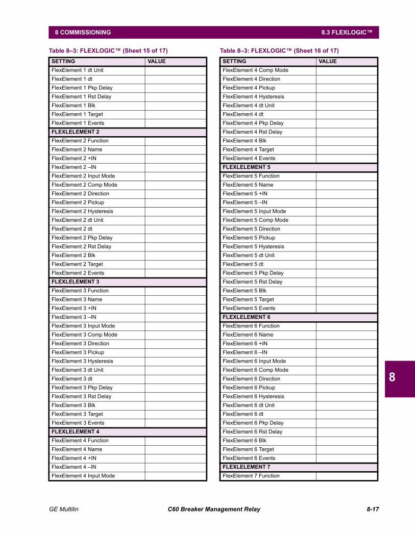
GE Multilin C60 Breaker Management Relay 8-17
8 COMMISSIONING 8.3 FLEXLOGIC
8
FlexElement 1 dt UnitFlexElement 1 dtFlexElement 1 Pkp DelayFlexElement 1 Rst DelayFlexElement 1 BlkFlexElement 1 TargetFlexElement 1 EventsFLEXLELEMENT 2FlexElement 2 FunctionFlexElement 2 NameFlexElement 2 +INFlexElement 2 INFlexElement 2 Input ModeFlexElement 2 Comp ModeFlexElement 2 DirectionFlexElement 2 PickupFlexElement 2 HysteresisFlexElement 2 dt UnitFlexElement 2 dtFlexElement 2 Pkp DelayFlexElement 2 Rst DelayFlexElement 2 BlkFlexElement 2 TargetFlexElement 2 EventsFLEXLELEMENT 3FlexElement 3 FunctionFlexElement 3 NameFlexElement 3 +INFlexElement 3 INFlexElement 3 Input ModeFlexElement 3 Comp ModeFlexElement 3 DirectionFlexElement 3 PickupFlexElement 3 HysteresisFlexElement 3 dt UnitFlexElement 3 dtFlexElement 3 Pkp DelayFlexElement 3 Rst DelayFlexElement 3 BlkFlexElement 3 TargetFlexElement 3 EventsFLEXLELEMENT 4FlexElement 4 FunctionFlexElement 4 NameFlexElement 4 +INFlexElement 4 INFlexElement 4 Input Mode
Table 83: FLEXLOGIC (Sheet 15 of 17)SETTING VALUE
FlexElement 4 Comp ModeFlexElement 4 DirectionFlexElement 4 PickupFlexElement 4 HysteresisFlexElement 4 dt UnitFlexElement 4 dtFlexElement 4 Pkp DelayFlexElement 4 Rst DelayFlexElement 4 BlkFlexElement 4 TargetFlexElement 4 EventsFLEXLELEMENT 5FlexElement 5 FunctionFlexElement 5 NameFlexElement 5 +INFlexElement 5 INFlexElement 5 Input ModeFlexElement 5 Comp ModeFlexElement 5 DirectionFlexElement 5 PickupFlexElement 5 HysteresisFlexElement 5 dt UnitFlexElement 5 dtFlexElement 5 Pkp DelayFlexElement 5 Rst DelayFlexElement 5 BlkFlexElement 5 TargetFlexElement 5 EventsFLEXLELEMENT 6FlexElement 6 FunctionFlexElement 6 NameFlexElement 6 +INFlexElement 6 INFlexElement 6 Input ModeFlexElement 6 Comp ModeFlexElement 6 DirectionFlexElement 6 PickupFlexElement 6 HysteresisFlexElement 6 dt UnitFlexElement 6 dtFlexElement 6 Pkp DelayFlexElement 6 Rst DelayFlexElement 6 BlkFlexElement 6 TargetFlexElement 6 EventsFLEXLELEMENT 7FlexElement 7 Function
Table 83: FLEXLOGIC (Sheet 16 of 17)SETTING VALUE
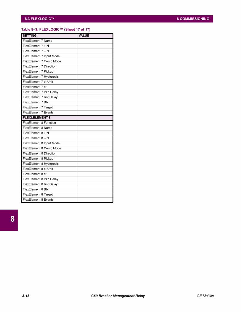
8-18 C60 Breaker Management Relay GE Multilin
8.3 FLEXLOGIC 8 COMMISSIONING
8
FlexElement 7 NameFlexElement 7 +INFlexElement 7 INFlexElement 7 Input ModeFlexElement 7 Comp ModeFlexElement 7 DirectionFlexElement 7 PickupFlexElement 7 HysteresisFlexElement 7 dt UnitFlexElement 7 dtFlexElement 7 Pkp DelayFlexElement 7 Rst DelayFlexElement 7 BlkFlexElement 7 TargetFlexElement 7 EventsFLEXLELEMENT 8FlexElement 8 FunctionFlexElement 8 NameFlexElement 8 +INFlexElement 8 INFlexElement 8 Input ModeFlexElement 8 Comp ModeFlexElement 8 DirectionFlexElement 8 PickupFlexElement 8 HysteresisFlexElement 8 dt UnitFlexElement 8 dtFlexElement 8 Pkp DelayFlexElement 8 Rst DelayFlexElement 8 BlkFlexElement 8 TargetFlexElement 8 Events
Table 83: FLEXLOGIC (Sheet 17 of 17)SETTING VALUE
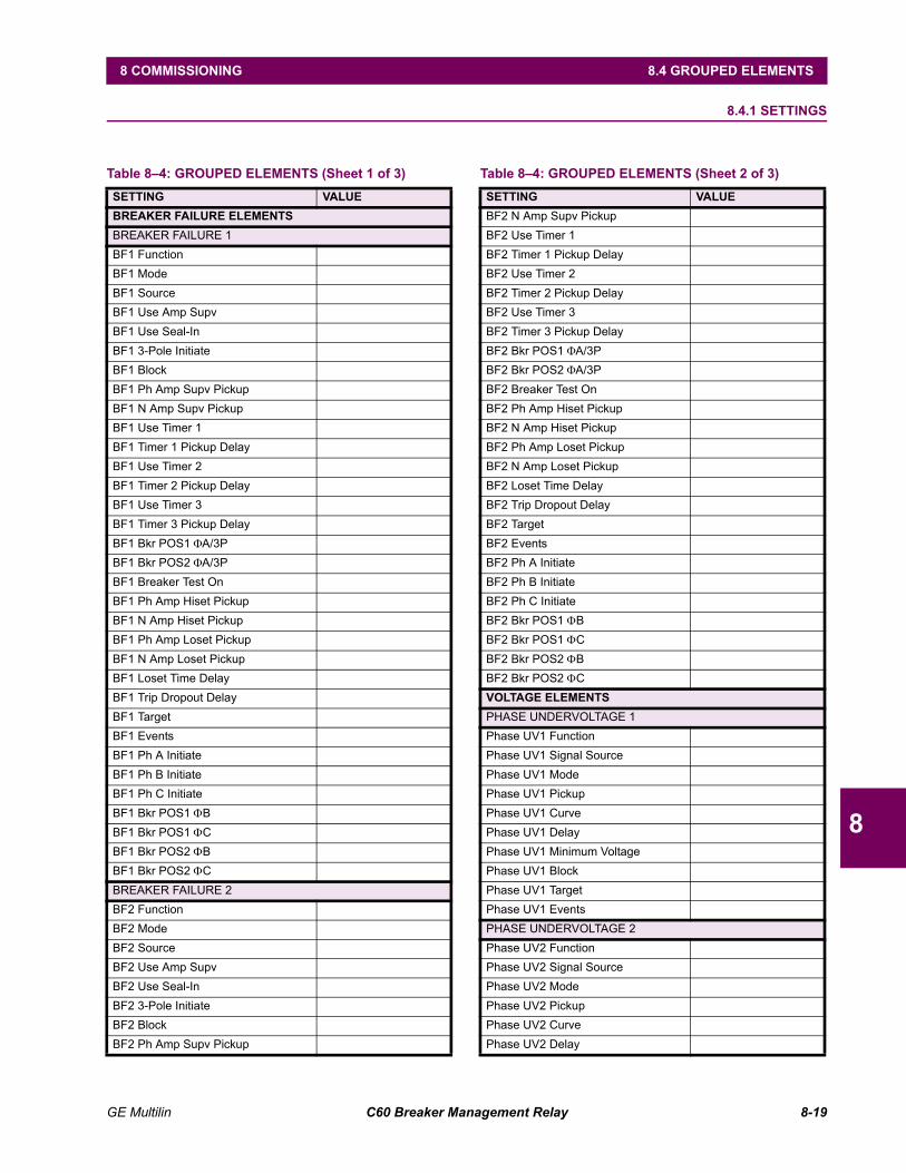
GE Multilin C60 Breaker Management Relay 8-19
8 COMMISSIONING 8.4 GROUPED ELEMENTS
8
8.4 GROUPED ELEMENTS 8.4.1 SETTINGS
Table 84: GROUPED ELEMENTS (Sheet 1 of 3)SETTING VALUEBREAKER FAILURE ELEMENTSBREAKER FAILURE 1BF1 FunctionBF1 ModeBF1 SourceBF1 Use Amp SupvBF1 Use Seal-InBF1 3-Pole InitiateBF1 BlockBF1 Ph Amp Supv PickupBF1 N Amp Supv PickupBF1 Use Timer 1BF1 Timer 1 Pickup DelayBF1 Use Timer 2BF1 Timer 2 Pickup DelayBF1 Use Timer 3BF1 Timer 3 Pickup DelayBF1 Bkr POS1 ΦA/3PBF1 Bkr POS2 ΦA/3PBF1 Breaker Test OnBF1 Ph Amp Hiset PickupBF1 N Amp Hiset PickupBF1 Ph Amp Loset PickupBF1 N Amp Loset PickupBF1 Loset Time DelayBF1 Trip Dropout DelayBF1 TargetBF1 EventsBF1 Ph A InitiateBF1 Ph B InitiateBF1 Ph C InitiateBF1 Bkr POS1 ΦBBF1 Bkr POS1 ΦCBF1 Bkr POS2 ΦBBF1 Bkr POS2 ΦCBREAKER FAILURE 2BF2 FunctionBF2 ModeBF2 SourceBF2 Use Amp SupvBF2 Use Seal-InBF2 3-Pole InitiateBF2 BlockBF2 Ph Amp Supv Pickup
BF2 N Amp Supv PickupBF2 Use Timer 1BF2 Timer 1 Pickup DelayBF2 Use Timer 2BF2 Timer 2 Pickup DelayBF2 Use Timer 3BF2 Timer 3 Pickup DelayBF2 Bkr POS1 ΦA/3PBF2 Bkr POS2 ΦA/3PBF2 Breaker Test OnBF2 Ph Amp Hiset PickupBF2 N Amp Hiset PickupBF2 Ph Amp Loset PickupBF2 N Amp Loset PickupBF2 Loset Time DelayBF2 Trip Dropout DelayBF2 TargetBF2 EventsBF2 Ph A InitiateBF2 Ph B InitiateBF2 Ph C InitiateBF2 Bkr POS1 ΦBBF2 Bkr POS1 ΦCBF2 Bkr POS2 ΦBBF2 Bkr POS2 ΦCVOLTAGE ELEMENTSPHASE UNDERVOLTAGE 1Phase UV1 FunctionPhase UV1 Signal SourcePhase UV1 ModePhase UV1 PickupPhase UV1 CurvePhase UV1 DelayPhase UV1 Minimum VoltagePhase UV1 BlockPhase UV1 TargetPhase UV1 EventsPHASE UNDERVOLTAGE 2Phase UV2 FunctionPhase UV2 Signal SourcePhase UV2 ModePhase UV2 PickupPhase UV2 CurvePhase UV2 Delay
Table 84: GROUPED ELEMENTS (Sheet 2 of 3)SETTING VALUE
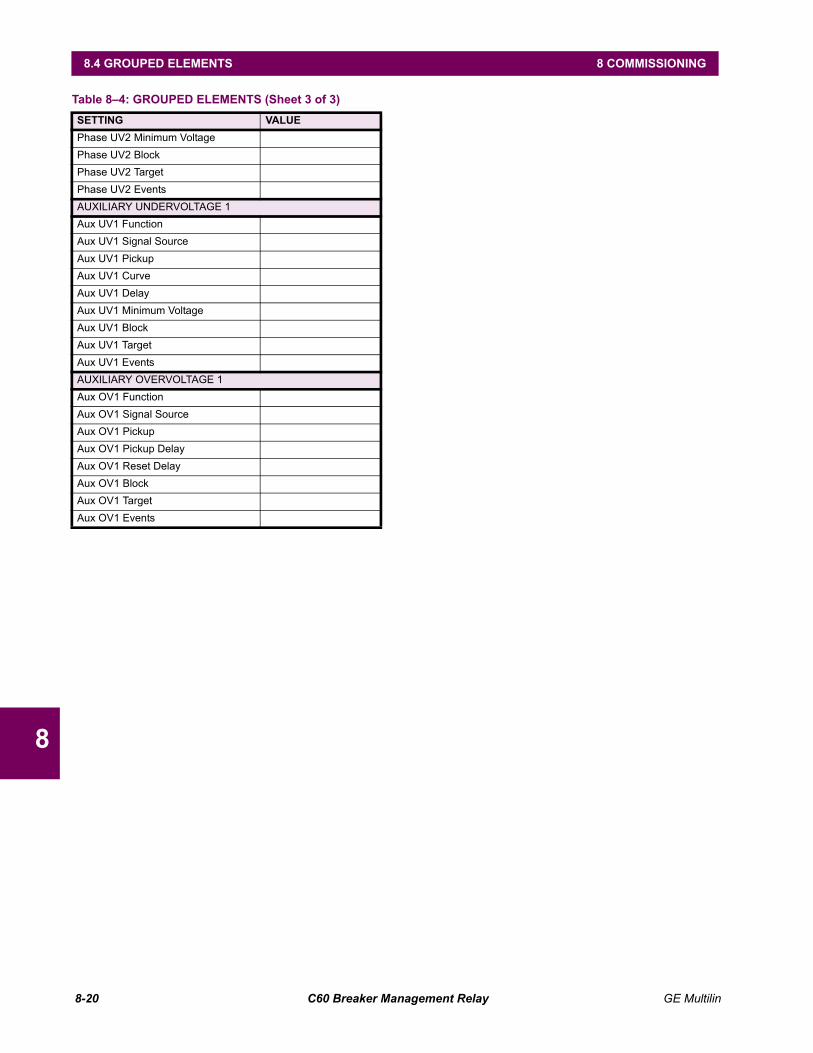
8-20 C60 Breaker Management Relay GE Multilin
8.4 GROUPED ELEMENTS 8 COMMISSIONING
8
Phase UV2 Minimum VoltagePhase UV2 BlockPhase UV2 TargetPhase UV2 EventsAUXILIARY UNDERVOLTAGE 1Aux UV1 FunctionAux UV1 Signal SourceAux UV1 PickupAux UV1 CurveAux UV1 DelayAux UV1 Minimum VoltageAux UV1 BlockAux UV1 TargetAux UV1 EventsAUXILIARY OVERVOLTAGE 1Aux OV1 FunctionAux OV1 Signal SourceAux OV1 PickupAux OV1 Pickup DelayAux OV1 Reset DelayAux OV1 BlockAux OV1 TargetAux OV1 Events
Table 84: GROUPED ELEMENTS (Sheet 3 of 3)SETTING VALUE

GE Multilin C60 Breaker Management Relay 8-21
8 COMMISSIONING 8.5 CONTROL ELEMENTS
8
8.5 CONTROL ELEMENTS 8.5.1 SETTINGS
Table 85: CONTROL ELEMENTS (Sheet 1 of 8)SETTING VALUESETTING GROUPSSetting Groups FunctionSetting Groups BlockGroup 2 Activate OnGroup 3 Activate OnGroup 4 Activate OnGroup 5 Activate OnGroup 6 Activate OnGroup 7 Activate OnGroup 8 Activate OnSetting Group EventsSYNCHROCHECK 1Synchk1 FunctionSynchk1 BlockSynchk1 V1 SourceSynchk1 V2 SourceSynchk1 Max Volt DiffSynchk1 Max Angle DiffSynchk1 Max Freq DiffSynchk1 Dead Source SelectSynchk1 Dead V1 Max VoltSynchk1 Dead V2 Max VoltSynchk1 Line V1 Min VoltSynchk1 Line V2 Min VoltSynchk1 TargetSynchk1 EventsSYNCHROCHECK 2Synchk2 FunctionSynchk2 BlockSynchk2 V1 SourceSynchk2 V2 SourceSynchk2 Max Volt DiffSynchk2 Max Angle DiffSynchk2 Max Freq DiffSynchk2 Dead Source SelectSynchk2 Dead V1 Max VoltSynchk2 Dead V2 Max VoltSynchk2 Line V1 Min VoltSynchk2 Line V2 Min VoltSynchk2 TargetSynchk2 EventsAUTORECLOSEAR FunctionAR Mode
AR Max Number of ShotsAR Block Bkr1AR Bkr 1 Mnl CloseAR Close Time Bkr1AR Blk Time Upon Man ClsAR 1P InitAR 3P InitAR 3P TD InitAR 3-P Dead Time 1AR 3-P Dead Time 2AR Extend Dead T 1AR Dead Time 1 ExtensionAR ResetAR Reset TimeAR BlockAR PauseAR Incomplete Seq TimeAR Block Bkr 2AR Bkr Mnl CloseAR Close Time Bkr2AR Transfer 1 to 2AR Transfer 2 to 1AR Bkr1 Fail OptionAR Bkr2 Fail OptionAR 1-P Dead TimeAR Bkr SequenceAR Transfer TimeAR EventDIGITAL ELEMENT 1Digital Element 1 FunctionDig Elem 1 NameDig Elem 1 InputDig Elem 1 Pickup DelayDig Elem 1 Reset DelayDig Elem 1 BlockDigital Element 1 TargetDigital Element 1 EventsDIGITAL ELEMENT 2Digital Element 2 FunctionDig Elem 2 NameDig Elem 2 InputDig Elem 2 Pickup DelayDig Elem 2 Reset DelayDig Elem 2 Block
Table 85: CONTROL ELEMENTS (Sheet 2 of 8)SETTING VALUE
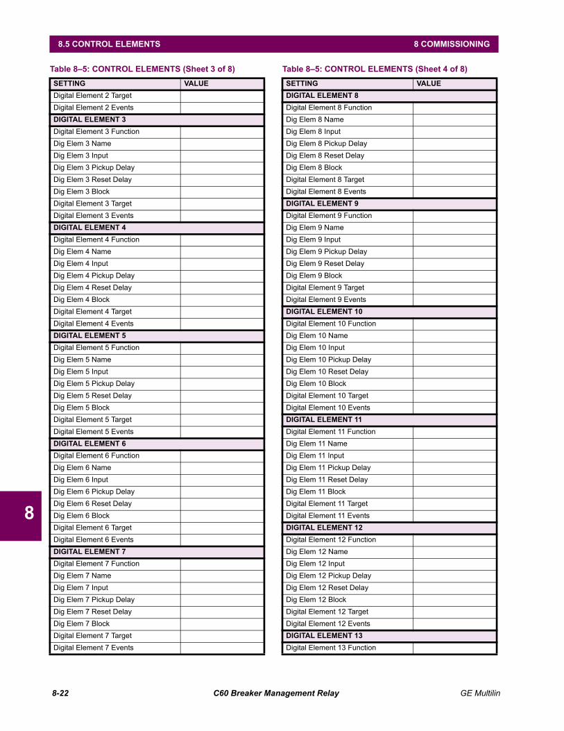
8-22 C60 Breaker Management Relay GE Multilin
8.5 CONTROL ELEMENTS 8 COMMISSIONING
8
Digital Element 2 TargetDigital Element 2 EventsDIGITAL ELEMENT 3Digital Element 3 FunctionDig Elem 3 NameDig Elem 3 InputDig Elem 3 Pickup DelayDig Elem 3 Reset DelayDig Elem 3 BlockDigital Element 3 TargetDigital Element 3 EventsDIGITAL ELEMENT 4Digital Element 4 FunctionDig Elem 4 NameDig Elem 4 InputDig Elem 4 Pickup DelayDig Elem 4 Reset DelayDig Elem 4 BlockDigital Element 4 TargetDigital Element 4 EventsDIGITAL ELEMENT 5Digital Element 5 FunctionDig Elem 5 NameDig Elem 5 InputDig Elem 5 Pickup DelayDig Elem 5 Reset DelayDig Elem 5 BlockDigital Element 5 TargetDigital Element 5 EventsDIGITAL ELEMENT 6Digital Element 6 FunctionDig Elem 6 NameDig Elem 6 InputDig Elem 6 Pickup DelayDig Elem 6 Reset DelayDig Elem 6 BlockDigital Element 6 TargetDigital Element 6 EventsDIGITAL ELEMENT 7Digital Element 7 FunctionDig Elem 7 NameDig Elem 7 InputDig Elem 7 Pickup DelayDig Elem 7 Reset DelayDig Elem 7 BlockDigital Element 7 TargetDigital Element 7 Events
Table 85: CONTROL ELEMENTS (Sheet 3 of 8)SETTING VALUE
DIGITAL ELEMENT 8Digital Element 8 FunctionDig Elem 8 NameDig Elem 8 InputDig Elem 8 Pickup DelayDig Elem 8 Reset DelayDig Elem 8 BlockDigital Element 8 TargetDigital Element 8 EventsDIGITAL ELEMENT 9Digital Element 9 FunctionDig Elem 9 NameDig Elem 9 InputDig Elem 9 Pickup DelayDig Elem 9 Reset DelayDig Elem 9 BlockDigital Element 9 TargetDigital Element 9 EventsDIGITAL ELEMENT 10Digital Element 10 FunctionDig Elem 10 NameDig Elem 10 InputDig Elem 10 Pickup DelayDig Elem 10 Reset DelayDig Elem 10 BlockDigital Element 10 TargetDigital Element 10 EventsDIGITAL ELEMENT 11Digital Element 11 FunctionDig Elem 11 NameDig Elem 11 InputDig Elem 11 Pickup DelayDig Elem 11 Reset DelayDig Elem 11 BlockDigital Element 11 TargetDigital Element 11 EventsDIGITAL ELEMENT 12Digital Element 12 FunctionDig Elem 12 NameDig Elem 12 InputDig Elem 12 Pickup DelayDig Elem 12 Reset DelayDig Elem 12 BlockDigital Element 12 TargetDigital Element 12 EventsDIGITAL ELEMENT 13Digital Element 13 Function
Table 85: CONTROL ELEMENTS (Sheet 4 of 8)SETTING VALUE
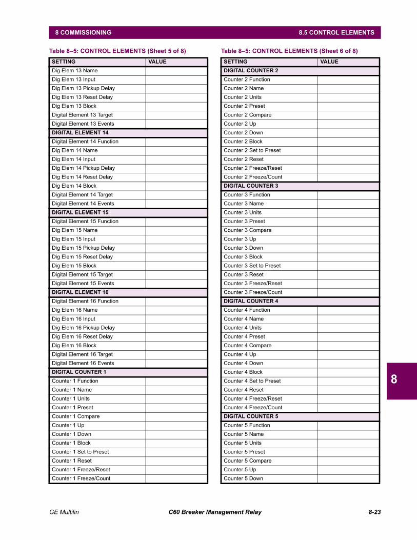
GE Multilin C60 Breaker Management Relay 8-23
8 COMMISSIONING 8.5 CONTROL ELEMENTS
8
Dig Elem 13 NameDig Elem 13 InputDig Elem 13 Pickup DelayDig Elem 13 Reset DelayDig Elem 13 BlockDigital Element 13 TargetDigital Element 13 EventsDIGITAL ELEMENT 14Digital Element 14 FunctionDig Elem 14 NameDig Elem 14 InputDig Elem 14 Pickup DelayDig Elem 14 Reset DelayDig Elem 14 BlockDigital Element 14 TargetDigital Element 14 EventsDIGITAL ELEMENT 15Digital Element 15 FunctionDig Elem 15 NameDig Elem 15 InputDig Elem 15 Pickup DelayDig Elem 15 Reset DelayDig Elem 15 BlockDigital Element 15 TargetDigital Element 15 EventsDIGITAL ELEMENT 16Digital Element 16 FunctionDig Elem 16 NameDig Elem 16 InputDig Elem 16 Pickup DelayDig Elem 16 Reset DelayDig Elem 16 BlockDigital Element 16 TargetDigital Element 16 EventsDIGITAL COUNTER 1Counter 1 FunctionCounter 1 NameCounter 1 UnitsCounter 1 PresetCounter 1 CompareCounter 1 UpCounter 1 DownCounter 1 BlockCounter 1 Set to PresetCounter 1 ResetCounter 1 Freeze/ResetCounter 1 Freeze/Count
Table 85: CONTROL ELEMENTS (Sheet 5 of 8)SETTING VALUE
DIGITAL COUNTER 2Counter 2 FunctionCounter 2 NameCounter 2 UnitsCounter 2 PresetCounter 2 CompareCounter 2 UpCounter 2 DownCounter 2 BlockCounter 2 Set to PresetCounter 2 ResetCounter 2 Freeze/ResetCounter 2 Freeze/CountDIGITAL COUNTER 3Counter 3 FunctionCounter 3 NameCounter 3 UnitsCounter 3 PresetCounter 3 CompareCounter 3 UpCounter 3 DownCounter 3 BlockCounter 3 Set to PresetCounter 3 ResetCounter 3 Freeze/ResetCounter 3 Freeze/CountDIGITAL COUNTER 4Counter 4 FunctionCounter 4 NameCounter 4 UnitsCounter 4 PresetCounter 4 CompareCounter 4 UpCounter 4 DownCounter 4 BlockCounter 4 Set to PresetCounter 4 ResetCounter 4 Freeze/ResetCounter 4 Freeze/CountDIGITAL COUNTER 5Counter 5 FunctionCounter 5 NameCounter 5 UnitsCounter 5 PresetCounter 5 CompareCounter 5 UpCounter 5 Down
Table 85: CONTROL ELEMENTS (Sheet 6 of 8)SETTING VALUE
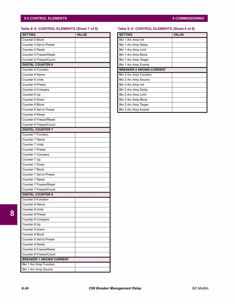
8-24 C60 Breaker Management Relay GE Multilin
8.5 CONTROL ELEMENTS 8 COMMISSIONING
8
Counter 5 BlockCounter 5 Set to PresetCounter 5 ResetCounter 5 Freeze/ResetCounter 5 Freeze/CountDIGITAL COUNTER 6Counter 6 FunctionCounter 6 NameCounter 6 UnitsCounter 6 PresetCounter 6 CompareCounter 6 UpCounter 6 DownCounter 6 BlockCounter 6 Set to PresetCounter 6 ResetCounter 6 Freeze/ResetCounter 6 Freeze/CountDIGITAL COUNTER 7Counter 7 FunctionCounter 7 NameCounter 7 UnitsCounter 7 PresetCounter 7 CompareCounter 7 UpCounter 7 DownCounter 7 BlockCounter 7 Set to PresetCounter 7 ResetCounter 7 Freeze/ResetCounter 7 Freeze/CountDIGITAL COUNTER 8Counter 8 FunctionCounter 8 NameCounter 8 UnitsCounter 8 PresetCounter 8 CompareCounter 8 UpCounter 8 DownCounter 8 BlockCounter 8 Set to PresetCounter 8 ResetCounter 8 Freeze/ResetCounter 8 Freeze/CountBREAKER 1 ARCING CURRENTBkr 1 Arc Amp FunctionBkr 1 Arc Amp Source
Table 85: CONTROL ELEMENTS (Sheet 7 of 8)SETTING VALUE
Bkr 1 Arc Amp InitBkr 1 Arc Amp DelayBkr 1 Arc Amp LimitBkr 1 Arc Amp BlockBkr 1 Arc Amp TargetBkr 1 Arc Amp EventsBREAKER 2 ARCING CURRENTBkr 2 Arc Amp FunctionBkr 2 Arc Amp SourceBkr 2 Arc Amp InitBkr 2 Arc Amp DelayBkr 2 Arc Amp LimitBkr 2 Arc Amp BlockBkr 2 Arc Amp TargetBkr 2 Arc Amp Events
Table 85: CONTROL ELEMENTS (Sheet 8 of 8)SETTING VALUE

GE Multilin C60 Breaker Management Relay 8-25
8 COMMISSIONING 8.6 INPUTS / OUTPUTS
8
8.6 INPUTS / OUTPUTS 8.6.1 CONTACT INPUTS
Table 86: CONTACT INPUTSCONTACT INPUT ID DEBNCE TIME EVENTS THRESHOLD
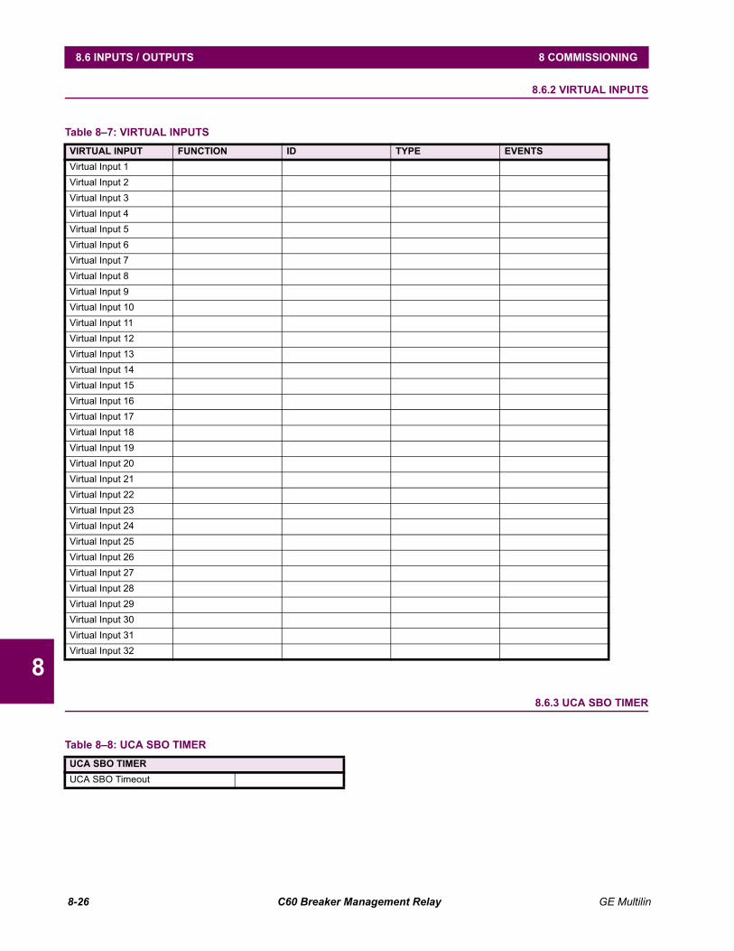
8-26 C60 Breaker Management Relay GE Multilin
8.6 INPUTS / OUTPUTS 8 COMMISSIONING
8
8.6.2 VIRTUAL INPUTS
8.6.3 UCA SBO TIMER
Table 87: VIRTUAL INPUTS VIRTUAL INPUT FUNCTION ID TYPE EVENTSVirtual Input 1Virtual Input 2Virtual Input 3Virtual Input 4Virtual Input 5Virtual Input 6Virtual Input 7Virtual Input 8Virtual Input 9Virtual Input 10Virtual Input 11Virtual Input 12Virtual Input 13Virtual Input 14Virtual Input 15Virtual Input 16Virtual Input 17Virtual Input 18Virtual Input 19Virtual Input 20Virtual Input 21Virtual Input 22Virtual Input 23Virtual Input 24Virtual Input 25Virtual Input 26Virtual Input 27Virtual Input 28Virtual Input 29Virtual Input 30Virtual Input 31Virtual Input 32
Table 88: UCA SBO TIMER UCA SBO TIMERUCA SBO Timeout
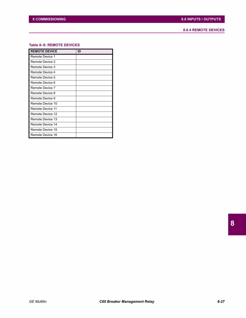
GE Multilin C60 Breaker Management Relay 8-27
8 COMMISSIONING 8.6 INPUTS / OUTPUTS
8
8.6.4 REMOTE DEVICES
Table 89: REMOTE DEVICES REMOTE DEVICE IDRemote Device 1Remote Device 2Remote Device 3Remote Device 4Remote Device 5Remote Device 6Remote Device 7Remote Device 8Remote Device 9Remote Device 10Remote Device 11Remote Device 12Remote Device 13Remote Device 14Remote Device 15Remote Device 16
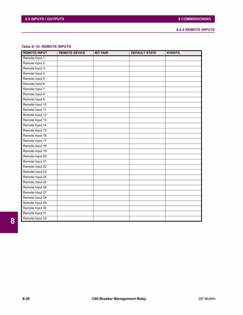
8-28 C60 Breaker Management Relay GE Multilin
8.6 INPUTS / OUTPUTS 8 COMMISSIONING
8
8.6.5 REMOTE INPUTS
Table 810: REMOTE INPUTS REMOTE INPUT REMOTE DEVICE BIT PAIR DEFAULT STATE EVENTSRemote Input 1Remote Input 2Remote Input 3Remote Input 4Remote Input 5Remote Input 6Remote Input 7Remote Input 8Remote Input 9Remote Input 10Remote Input 11Remote Input 12Remote Input 13Remote Input 14Remote Input 15Remote Input 16Remote Input 17Remote Input 18Remote Input 19Remote Input 20Remote Input 21Remote Input 22Remote Input 23Remote Input 24Remote Input 25Remote Input 26Remote Input 27Remote Input 28Remote Input 29Remote Input 30Remote Input 31Remote Input 32
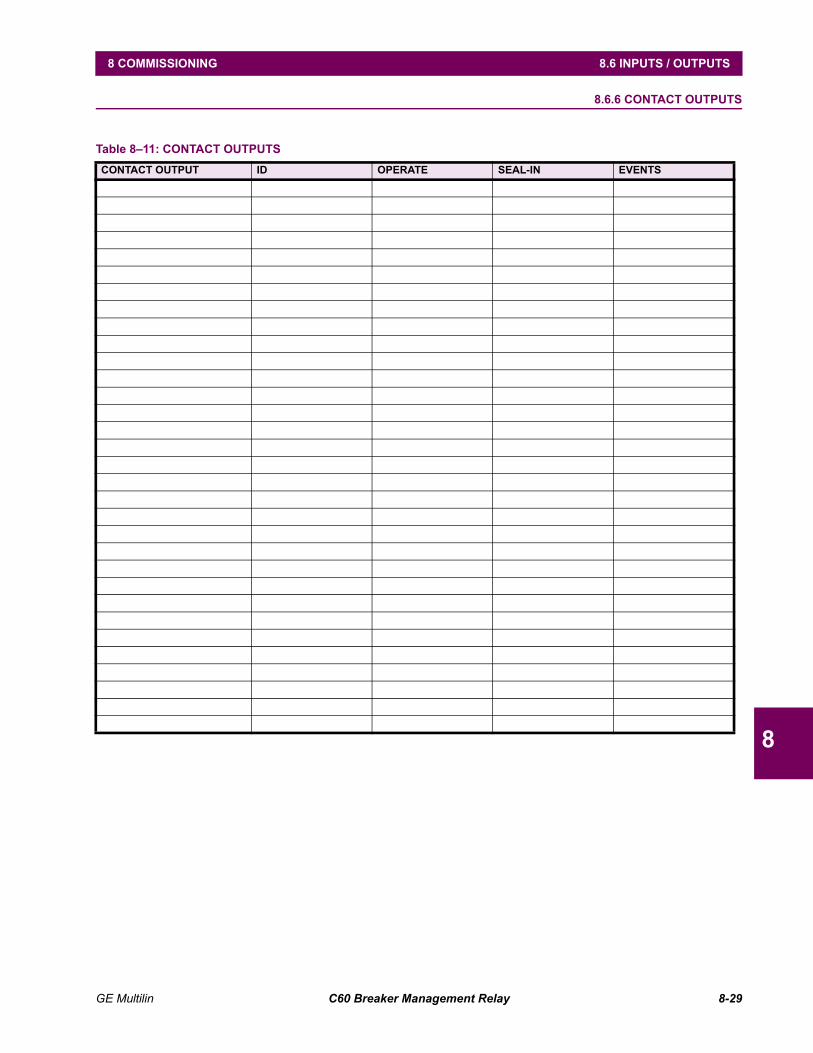
GE Multilin C60 Breaker Management Relay 8-29
8 COMMISSIONING 8.6 INPUTS / OUTPUTS
8
8.6.6 CONTACT OUTPUTS
Table 811: CONTACT OUTPUTS CONTACT OUTPUT ID OPERATE SEAL-IN EVENTS
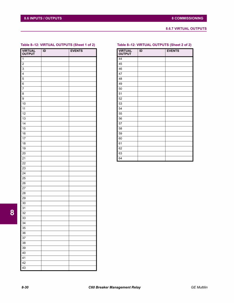
8-30 C60 Breaker Management Relay GE Multilin
8.6 INPUTS / OUTPUTS 8 COMMISSIONING
8
8.6.7 VIRTUAL OUTPUTS
Table 812: VIRTUAL OUTPUTS (Sheet 1 of 2)VIRTUALOUTPUT
ID EVENTS
12345678910111213141516171819202122232425262728293031323334353637383940414243
444546474849505152535455565758596061626364
Table 812: VIRTUAL OUTPUTS (Sheet 2 of 2)VIRTUALOUTPUT
ID EVENTS
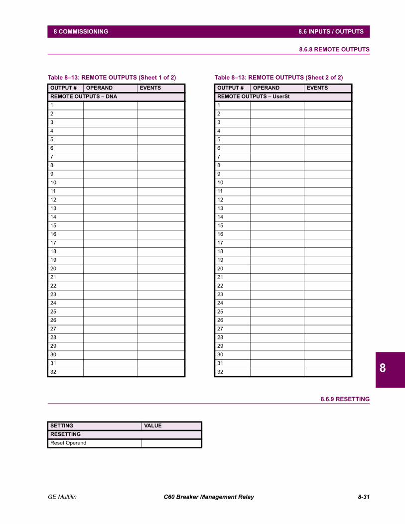
GE Multilin C60 Breaker Management Relay 8-31
8 COMMISSIONING 8.6 INPUTS / OUTPUTS
8
8.6.8 REMOTE OUTPUTS
8.6.9 RESETTING
Table 813: REMOTE OUTPUTS (Sheet 1 of 2)OUTPUT # OPERAND EVENTSREMOTE OUTPUTS DNA1234567891011121314151617181920212223242526272829303132
REMOTE OUTPUTS UserSt1234567891011121314151617181920212223242526272829303132
Table 813: REMOTE OUTPUTS (Sheet 2 of 2)OUTPUT # OPERAND EVENTS
SETTING VALUERESETTINGReset Operand
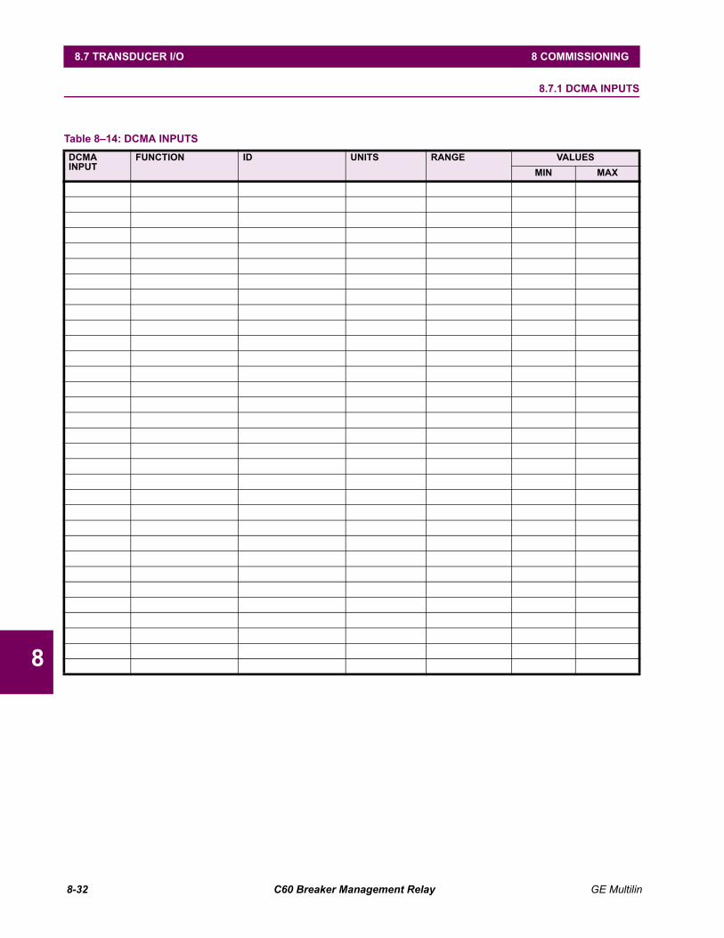
8-32 C60 Breaker Management Relay GE Multilin
8.7 TRANSDUCER I/O 8 COMMISSIONING
8
8.7 TRANSDUCER I/O 8.7.1 DCMA INPUTS
Table 814: DCMA INPUTS DCMA INPUT
FUNCTION ID UNITS RANGE VALUESMIN MAX
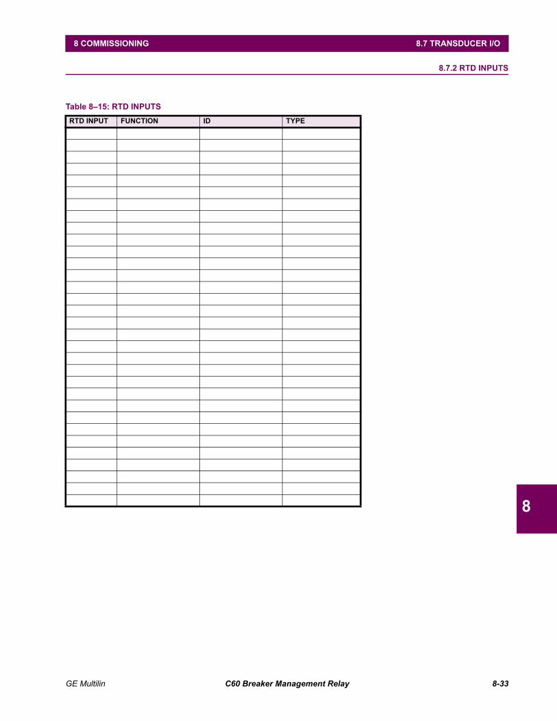
GE Multilin C60 Breaker Management Relay 8-33
8 COMMISSIONING 8.7 TRANSDUCER I/O
8
8.7.2 RTD INPUTS
Table 815: RTD INPUTS RTD INPUT FUNCTION ID TYPE
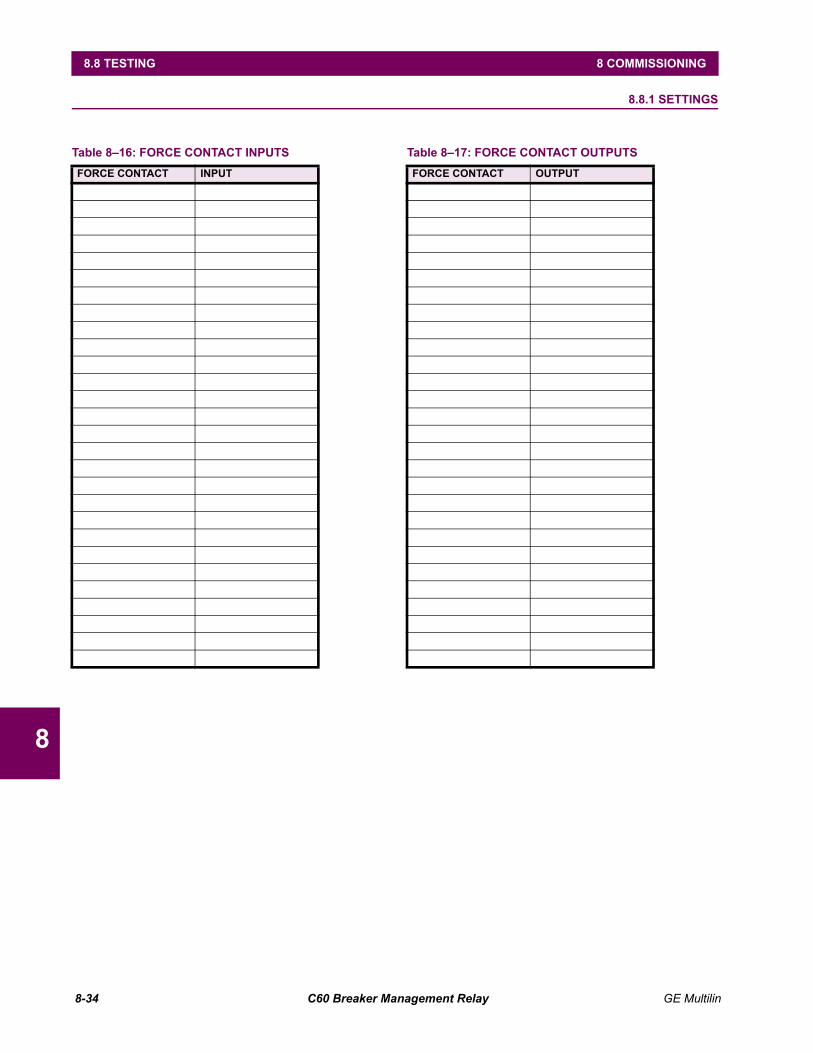
8-34 C60 Breaker Management Relay GE Multilin
8.8 TESTING 8 COMMISSIONING
8
8.8 TESTING 8.8.1 SETTINGS
Table 816: FORCE CONTACT INPUTSFORCE CONTACT INPUT
Table 817: FORCE CONTACT OUTPUTSFORCE CONTACT OUTPUT
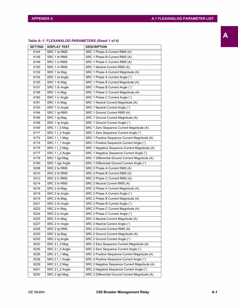
GE Multilin C60 Breaker Management Relay A-1
APPENDIX A A.1 FLEXANALOG PARAMETER LIST
AAPPENDIX A FLEXANALOG PARAMETERSA.1 FLEXANALOG PARAMETER LIST
Table A1: FLEXANALOG PARAMETERS (Sheet 1 of 4)SETTING DISPLAY TEXT DESCRIPTION
6144 SRC 1 Ia RMS SRC 1 Phase A Current RMS (A)6146 SRC 1 Ib RMS SRC 1 Phase B Current RMS (A)6148 SRC 1 Ic RMS SRC 1 Phase C Current RMS (A)6150 SRC 1 In RMS SRC 1 Neutral Current RMS (A)6152 SRC 1 Ia Mag SRC 1 Phase A Current Magnitude (A)6154 SRC 1 Ia Angle SRC 1 Phase A Current Angle (°)6155 SRC 1 Ib Mag SRC 1 Phase B Current Magnitude (A)6157 SRC 1 Ib Angle SRC 1 Phase B Current Angle (°)6158 SRC 1 Ic Mag SRC 1 Phase C Current Magnitude (A)6160 SRC 1 Ic Angle SRC 1 Phase C Current Angle (°)6161 SRC 1 In Mag SRC 1 Neutral Current Magnitude (A)6163 SRC 1 In Angle SRC 1 Neutral Current Angle (°)6164 SRC 1 Ig RMS SRC 1 Ground Current RMS (A)6166 SRC 1 Ig Mag SRC 1 Ground Current Magnitude (A)6168 SRC 1 Ig Angle SRC 1 Ground Current Angle (°)6169 SRC 1 I_0 Mag SRC 1 Zero Sequence Current Magnitude (A)6171 SRC 1 I_0 Angle SRC 1 Zero Sequence Current Angle (°)6172 SRC 1 I_1 Mag SRC 1 Positive Sequence Current Magnitude (A)6174 SRC 1 I_1 Angle SRC 1 Positive Sequence Current Angle (°)6175 SRC 1 I_2 Mag SRC 1 Negative Sequence Current Magnitude (A)6177 SRC 1 I_2 Angle SRC 1 Negative Sequence Current Angle (°)6178 SRC 1 Igd Mag SRC 1 Differential Ground Current Magnitude (A)6180 SRC 1 Igd Angle SRC 1 Differential Ground Current Angle (°)6208 SRC 2 Ia RMS SRC 2 Phase A Current RMS (A)6210 SRC 2 Ib RMS SRC 2 Phase B Current RMS (A)6212 SRC 2 Ic RMS SRC 2 Phase C Current RMS (A)6214 SRC 2 In RMS SRC 2 Neutral Current RMS (A)6216 SRC 2 Ia Mag SRC 2 Phase A Current Magnitude (A)6218 SRC 2 Ia Angle SRC 2 Phase A Current Angle (°)6219 SRC 2 Ib Mag SRC 2 Phase B Current Magnitude (A)6221 SRC 2 Ib Angle SRC 2 Phase B Current Angle (°)6222 SRC 2 Ic Mag SRC 2 Phase C Current Magnitude (A)6224 SRC 2 Ic Angle SRC 2 Phase C Current Angle (°)6225 SRC 2 In Mag SRC 2 Neutral Current Magnitude (A)6227 SRC 2 In Angle SRC 2 Neutral Current Angle (°)6228 SRC 2 Ig RMS SRC 2 Ground Current RMS (A)6230 SRC 2 Ig Mag SRC 2 Ground Current Magnitude (A)6232 SRC 2 Ig Angle SRC 2 Ground Current Angle (°)6233 SRC 2 I_0 Mag SRC 2 Zero Sequence Current Magnitude (A)6235 SRC 2 I_0 Angle SRC 2 Zero Sequence Current Angle (°)6236 SRC 2 I_1 Mag SRC 2 Positive Sequence Current Magnitude (A)6238 SRC 2 I_1 Angle SRC 2 Positive Sequence Current Angle (°)6239 SRC 2 I_2 Mag SRC 2 Negative Sequence Current Magnitude (A)6241 SRC 2 I_2 Angle SRC 2 Negative Sequence Current Angle (°)6242 SRC 2 Igd Mag SRC 2 Differential Ground Current Magnitude (A)
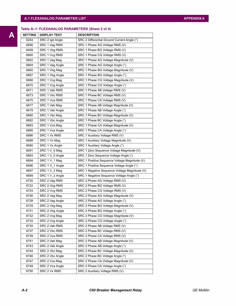
A-2 C60 Breaker Management Relay GE Multilin
A.1 FLEXANALOG PARAMETER LIST APPENDIX A
A6244 SRC 2 Igd Angle SRC 2 Differential Ground Current Angle (°)6656 SRC 1 Vag RMS SRC 1 Phase AG Voltage RMS (V)6658 SRC 1 Vbg RMS SRC 1 Phase BG Voltage RMS (V)6660 SRC 1 Vcg RMS SRC 1 Phase CG Voltage RMS (V)6662 SRC 1 Vag Mag SRC 1 Phase AG Voltage Magnitude (V)6664 SRC 1 Vag Angle SRC 1 Phase AG Voltage Angle (°)6665 SRC 1 Vbg Mag SRC 1 Phase BG Voltage Magnitude (V)6667 SRC 1 Vbg Angle SRC 1 Phase BG Voltage Angle (°)6668 SRC 1 Vcg Mag SRC 1 Phase CG Voltage Magnitude (V)6670 SRC 1 Vcg Angle SRC 1 Phase CG Voltage Angle (°)6671 SRC 1 Vab RMS SRC 1 Phase AB Voltage RMS (V)6673 SRC 1 Vbc RMS SRC 1 Phase BC Voltage RMS (V)6675 SRC 1 Vca RMS SRC 1 Phase CA Voltage RMS (V)6677 SRC 1 Vab Mag SRC 1 Phase AB Voltage Magnitude (V)6679 SRC 1 Vab Angle SRC 1 Phase AB Voltage Angle (°)6680 SRC 1 Vbc Mag SRC 1 Phase BC Voltage Magnitude (V)6682 SRC 1 Vbc Angle SRC 1 Phase BC Voltage Angle (°)6683 SRC 1 Vca Mag SRC 1 Phase CA Voltage Magnitude (V)6685 SRC 1 Vca Angle SRC 1 Phase CA Voltage Angle (°)6686 SRC 1 Vx RMS SRC 1 Auxiliary Voltage RMS (V)6688 SRC 1 Vx Mag SRC 1 Auxiliary Voltage Magnitude (V)6690 SRC 1 Vx Angle SRC 1 Auxiliary Voltage Angle (°)6691 SRC 1 V_0 Mag SRC 1 Zero Sequence Voltage Magnitude (V)6693 SRC 1 V_0 Angle SRC 1 Zero Sequence Voltage Angle (°)6694 SRC 1 V_1 Mag SRC 1 Positive Sequence Voltage Magnitude (V)6696 SRC 1 V_1 Angle SRC 1 Positive Sequence Voltage Angle (°)6697 SRC 1 V_2 Mag SRC 1 Negative Sequence Voltage Magnitude (V)6699 SRC 1 V_2 Angle SRC 1 Negative Sequence Voltage Angle (°)6720 SRC 2 Vag RMS SRC 2 Phase AG Voltage RMS (V)6722 SRC 2 Vbg RMS SRC 2 Phase BG Voltage RMS (V)6724 SRC 2 Vcg RMS SRC 2 Phase CG Voltage RMS (V)6726 SRC 2 Vag Mag SRC 2 Phase AG Voltage Magnitude (V)6728 SRC 2 Vag Angle SRC 2 Phase AG Voltage Angle (°)6729 SRC 2 Vbg Mag SRC 2 Phase BG Voltage Magnitude (V)6731 SRC 2 Vbg Angle SRC 2 Phase BG Voltage Angle (°)6732 SRC 2 Vcg Mag SRC 2 Phase CG Voltage Magnitude (V)6734 SRC 2 Vcg Angle SRC 2 Phase CG Voltage Angle (°)6735 SRC 2 Vab RMS SRC 2 Phase AB Voltage RMS (V)6737 SRC 2 Vbc RMS SRC 2 Phase BC Voltage RMS (V)6739 SRC 2 Vca RMS SRC 2 Phase CA Voltage RMS (V)6741 SRC 2 Vab Mag SRC 2 Phase AB Voltage Magnitude (V)6743 SRC 2 Vab Angle SRC 2 Phase AB Voltage Angle (°)6744 SRC 2 Vbc Mag SRC 2 Phase BC Voltage Magnitude (V)6746 SRC 2 Vbc Angle SRC 2 Phase BC Voltage Angle (°)6747 SRC 2 Vca Mag SRC 2 Phase CA Voltage Magnitude (V)6749 SRC 2 Vca Angle SRC 2 Phase CA Voltage Angle (°)6750 SRC 2 Vx RMS SRC 2 Auxiliary Voltage RMS (V)
Table A1: FLEXANALOG PARAMETERS (Sheet 2 of 4)SETTING DISPLAY TEXT DESCRIPTION
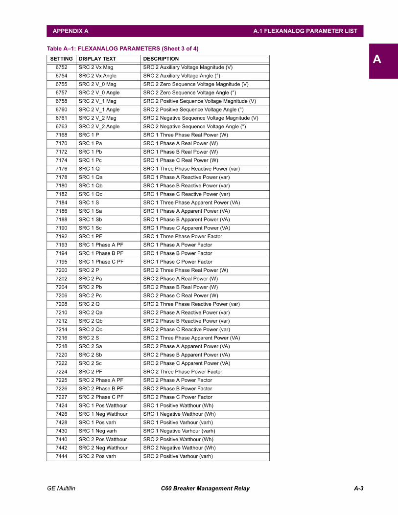
GE Multilin C60 Breaker Management Relay A-3
APPENDIX A A.1 FLEXANALOG PARAMETER LIST
A6752 SRC 2 Vx Mag SRC 2 Auxiliary Voltage Magnitude (V)6754 SRC 2 Vx Angle SRC 2 Auxiliary Voltage Angle (°)6755 SRC 2 V_0 Mag SRC 2 Zero Sequence Voltage Magnitude (V)6757 SRC 2 V_0 Angle SRC 2 Zero Sequence Voltage Angle (°)6758 SRC 2 V_1 Mag SRC 2 Positive Sequence Voltage Magnitude (V)6760 SRC 2 V_1 Angle SRC 2 Positive Sequence Voltage Angle (°)6761 SRC 2 V_2 Mag SRC 2 Negative Sequence Voltage Magnitude (V)6763 SRC 2 V_2 Angle SRC 2 Negative Sequence Voltage Angle (°)7168 SRC 1 P SRC 1 Three Phase Real Power (W)7170 SRC 1 Pa SRC 1 Phase A Real Power (W)7172 SRC 1 Pb SRC 1 Phase B Real Power (W)7174 SRC 1 Pc SRC 1 Phase C Real Power (W)7176 SRC 1 Q SRC 1 Three Phase Reactive Power (var)7178 SRC 1 Qa SRC 1 Phase A Reactive Power (var)7180 SRC 1 Qb SRC 1 Phase B Reactive Power (var)7182 SRC 1 Qc SRC 1 Phase C Reactive Power (var)7184 SRC 1 S SRC 1 Three Phase Apparent Power (VA)7186 SRC 1 Sa SRC 1 Phase A Apparent Power (VA)7188 SRC 1 Sb SRC 1 Phase B Apparent Power (VA)7190 SRC 1 Sc SRC 1 Phase C Apparent Power (VA)7192 SRC 1 PF SRC 1 Three Phase Power Factor7193 SRC 1 Phase A PF SRC 1 Phase A Power Factor7194 SRC 1 Phase B PF SRC 1 Phase B Power Factor7195 SRC 1 Phase C PF SRC 1 Phase C Power Factor7200 SRC 2 P SRC 2 Three Phase Real Power (W)7202 SRC 2 Pa SRC 2 Phase A Real Power (W)7204 SRC 2 Pb SRC 2 Phase B Real Power (W)7206 SRC 2 Pc SRC 2 Phase C Real Power (W)7208 SRC 2 Q SRC 2 Three Phase Reactive Power (var)7210 SRC 2 Qa SRC 2 Phase A Reactive Power (var)7212 SRC 2 Qb SRC 2 Phase B Reactive Power (var)7214 SRC 2 Qc SRC 2 Phase C Reactive Power (var)7216 SRC 2 S SRC 2 Three Phase Apparent Power (VA)7218 SRC 2 Sa SRC 2 Phase A Apparent Power (VA)7220 SRC 2 Sb SRC 2 Phase B Apparent Power (VA)7222 SRC 2 Sc SRC 2 Phase C Apparent Power (VA)7224 SRC 2 PF SRC 2 Three Phase Power Factor7225 SRC 2 Phase A PF SRC 2 Phase A Power Factor7226 SRC 2 Phase B PF SRC 2 Phase B Power Factor7227 SRC 2 Phase C PF SRC 2 Phase C Power Factor7424 SRC 1 Pos Watthour SRC 1 Positive Watthour (Wh)7426 SRC 1 Neg Watthour SRC 1 Negative Watthour (Wh)7428 SRC 1 Pos varh SRC 1 Positive Varhour (varh)7430 SRC 1 Neg varh SRC 1 Negative Varhour (varh)7440 SRC 2 Pos Watthour SRC 2 Positive Watthour (Wh)7442 SRC 2 Neg Watthour SRC 2 Negative Watthour (Wh)7444 SRC 2 Pos varh SRC 2 Positive Varhour (varh)
Table A1: FLEXANALOG PARAMETERS (Sheet 3 of 4)SETTING DISPLAY TEXT DESCRIPTION
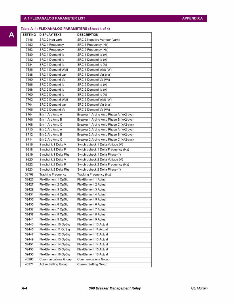
A-4 C60 Breaker Management Relay GE Multilin
A.1 FLEXANALOG PARAMETER LIST APPENDIX A
A7446 SRC 2 Neg varh SRC 2 Negative Varhour (varh)7552 SRC 1 Frequency SRC 1 Frequency (Hz)7553 SRC 2 Frequency SRC 2 Frequency (Hz)7680 SRC 1 Demand Ia SRC 1 Demand Ia (A)7682 SRC 1 Demand Ib SRC 1 Demand Ib (A)7684 SRC 1 Demand Ic SRC 1 Demand Ic (A)7686 SRC 1 Demand Watt SRC 1 Demand Watt (W)7688 SRC 1 Demand var SRC 1 Demand Var (var)7690 SRC 1 Demand Va SRC 1 Demand Va (VA)7696 SRC 2 Demand Ia SRC 2 Demand Ia (A)7698 SRC 2 Demand Ib SRC 2 Demand Ib (A)7700 SRC 2 Demand Ic SRC 2 Demand Ic (A)7702 SRC 2 Demand Watt SRC 2 Demand Watt (W)7704 SRC 2 Demand var SRC 2 Demand Var (var)7706 SRC 2 Demand Va SRC 2 Demand Va (VA)8704 Brk 1 Arc Amp A Breaker 1 Arcing Amp Phase A (kA2-cyc)8706 Brk 1 Arc Amp B Breaker 1 Arcing Amp Phase B (kA2-cyc)8708 Brk 1 Arc Amp C Breaker 1 Arcing Amp Phase C (kA2-cyc)8710 Brk 2 Arc Amp A Breaker 2 Arcing Amp Phase A (kA2-cyc)8712 Brk 2 Arc Amp B Breaker 2 Arcing Amp Phase B (kA2-cyc)8714 Brk 2 Arc Amp C Breaker 2 Arcing Amp Phase C (kA2-cyc)9216 Synchchk 1 Delta V Synchrocheck 1 Delta Voltage (V)9218 Synchchk 1 Delta F Synchrocheck 1 Delta Frequency (Hz)9219 Synchchk 1 Delta Phs Synchrocheck 1 Delta Phase (°)9220 Synchchk 2 Delta V Synchrocheck 2 Delta Voltage (V)9222 Synchchk 2 Delta F Synchrocheck 2 Delta Frequency (Hz)9223 Synchchk 2 Delta Phs Synchrocheck 2 Delta Phase (°)
32768 Tracking Frequency Tracking Frequency (Hz)39425 FlexElement 1 OpSig FlexElement 1 Actual39427 FlexElement 2 OpSig FlexElement 2 Actual39429 FlexElement 3 OpSig FlexElement 3 Actual39431 FlexElement 4 OpSig FlexElement 4 Actual39433 FlexElement 5 OpSig FlexElement 5 Actual39435 FlexElement 6 OpSig FlexElement 6 Actual39437 FlexElement 7 OpSig FlexElement 7 Actual39439 FlexElement 8 OpSig FlexElement 8 Actual39441 FlexElement 9 OpSig FlexElement 9 Actual39443 FlexElement 10 OpSig FlexElement 10 Actual39445 FlexElement 11 OpSig FlexElement 11 Actual39447 FlexElement 12 OpSig FlexElement 12 Actual39449 FlexElement 13 OpSig FlexElement 13 Actual39451 FlexElement 14 OpSig FlexElement 14 Actual39453 FlexElement 15 OpSig FlexElement 15 Actual39455 FlexElement 16 OpSig FlexElement 16 Actual40960 Communications Group Communications Group40971 Active Setting Group Current Setting Group
Table A1: FLEXANALOG PARAMETERS (Sheet 4 of 4)SETTING DISPLAY TEXT DESCRIPTION
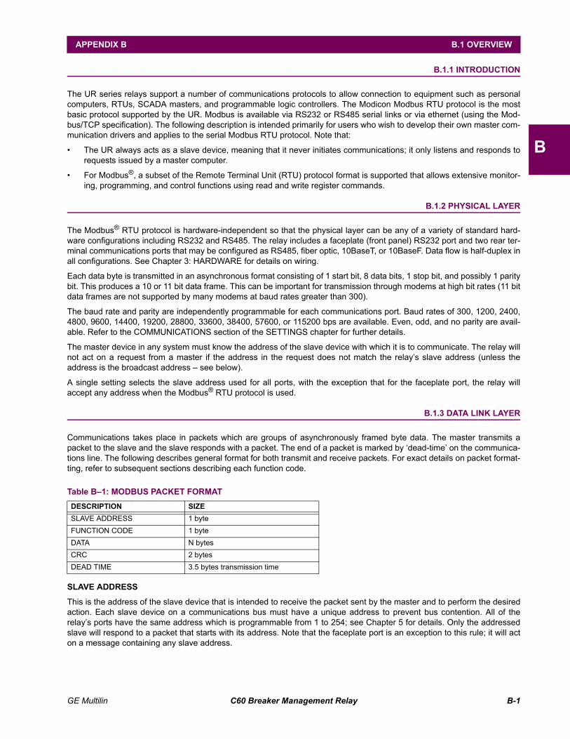
GE Multilin C60 Breaker Management Relay B-1
APPENDIX B B.1 OVERVIEW
B
APPENDIX B MODBUS® RTU PROTOCOLB.1 OVERVIEW B.1.1 INTRODUCTION
The UR series relays support a number of communications protocols to allow connection to equipment such as personalcomputers, RTUs, SCADA masters, and programmable logic controllers. The Modicon Modbus RTU protocol is the mostbasic protocol supported by the UR. Modbus is available via RS232 or RS485 serial links or via ethernet (using the Mod-bus/TCP specification). The following description is intended primarily for users who wish to develop their own master com-munication drivers and applies to the serial Modbus RTU protocol. Note that:
The UR always acts as a slave device, meaning that it never initiates communications; it only listens and responds torequests issued by a master computer.
For Modbus®, a subset of the Remote Terminal Unit (RTU) protocol format is supported that allows extensive monitor-ing, programming, and control functions using read and write register commands.
B.1.2 PHYSICAL LAYER
The Modbus® RTU protocol is hardware-independent so that the physical layer can be any of a variety of standard hard-ware configurations including RS232 and RS485. The relay includes a faceplate (front panel) RS232 port and two rear ter-minal communications ports that may be configured as RS485, fiber optic, 10BaseT, or 10BaseF. Data flow is half-duplex inall configurations. See Chapter 3: HARDWARE for details on wiring.
Each data byte is transmitted in an asynchronous format consisting of 1 start bit, 8 data bits, 1 stop bit, and possibly 1 paritybit. This produces a 10 or 11 bit data frame. This can be important for transmission through modems at high bit rates (11 bitdata frames are not supported by many modems at baud rates greater than 300).
The baud rate and parity are independently programmable for each communications port. Baud rates of 300, 1200, 2400,4800, 9600, 14400, 19200, 28800, 33600, 38400, 57600, or 115200 bps are available. Even, odd, and no parity are avail-able. Refer to the COMMUNICATIONS section of the SETTINGS chapter for further details.
The master device in any system must know the address of the slave device with which it is to communicate. The relay willnot act on a request from a master if the address in the request does not match the relays slave address (unless theaddress is the broadcast address see below).
A single setting selects the slave address used for all ports, with the exception that for the faceplate port, the relay willaccept any address when the Modbus® RTU protocol is used.
B.1.3 DATA LINK LAYER
Communications takes place in packets which are groups of asynchronously framed byte data. The master transmits apacket to the slave and the slave responds with a packet. The end of a packet is marked by dead-time on the communica-tions line. The following describes general format for both transmit and receive packets. For exact details on packet format-ting, refer to subsequent sections describing each function code.
SLAVE ADDRESS
This is the address of the slave device that is intended to receive the packet sent by the master and to perform the desiredaction. Each slave device on a communications bus must have a unique address to prevent bus contention. All of therelays ports have the same address which is programmable from 1 to 254; see Chapter 5 for details. Only the addressedslave will respond to a packet that starts with its address. Note that the faceplate port is an exception to this rule; it will acton a message containing any slave address.
Table B1: MODBUS PACKET FORMATDESCRIPTION SIZESLAVE ADDRESS 1 byteFUNCTION CODE 1 byteDATA N bytesCRC 2 bytesDEAD TIME 3.5 bytes transmission time
B-2 C60 Breaker Management Relay GE Multilin
B.1 OVERVIEW APPENDIX B
B
A master transmit packet with a slave address of 0 indicates a broadcast command. All slaves on the communication linkwill take action based on the packet, but none will respond to the master. Broadcast mode is only recognized when associ-ated with FUNCTION CODE 05h. For any other function code, a packet with broadcast mode slave address 0 will beignored.
FUNCTION CODE
This is one of the supported functions codes of the unit which tells the slave what action to perform. See the SUPPORTEDFUNCTION CODES section for complete details. An exception response from the slave is indicated by setting the highorder bit of the function code in the response packet. See the EXCEPTION RESPONSES section for further details.
DATA
This will be a variable number of bytes depending on the function code. This may include actual values, settings, oraddresses sent by the master to the slave or by the slave to the master.
CRC
This is a two byte error checking code. The RTU version of Modbus® includes a 16 bit cyclic redundancy check (CRC-16)with every packet which is an industry standard method used for error detection. If a Modbus® slave device receives apacket in which an error is indicated by the CRC, the slave device will not act upon or respond to the packet thus preventingany erroneous operations. See the CRC-16 ALGORITHM section for a description of how to calculate the CRC.
DEAD TIME
A packet is terminated when no data is received for a period of 3.5 byte transmission times (about 15 ms at 2400 bps, 2 msat 19200 bps, and 300 µs at 115200 bps). Consequently, the transmitting device must not allow gaps between bytes longerthan this interval. Once the dead time has expired without a new byte transmission, all slaves start listening for a newpacket from the master except for the addressed slave.
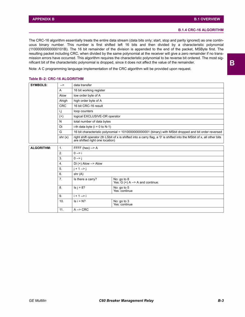
GE Multilin C60 Breaker Management Relay B-3
APPENDIX B B.1 OVERVIEW
B
B.1.4 CRC-16 ALGORITHM
The CRC-16 algorithm essentially treats the entire data stream (data bits only; start, stop and parity ignored) as one contin-uous binary number. This number is first shifted left 16 bits and then divided by a characteristic polynomial(11000000000000101B). The 16 bit remainder of the division is appended to the end of the packet, MSByte first. Theresulting packet including CRC, when divided by the same polynomial at the receiver will give a zero remainder if no trans-mission errors have occurred. This algorithm requires the characteristic polynomial to be reverse bit ordered. The most sig-nificant bit of the characteristic polynomial is dropped, since it does not affect the value of the remainder.
Note: A C programming language implementation of the CRC algorithm will be provided upon request.
Table B2: CRC-16 ALGORITHMSYMBOLS: --> data transfer
A 16 bit working registerAlow low order byte of AAhigh high order byte of ACRC 16 bit CRC-16 resulti,j loop counters(+) logical EXCLUSIVE-OR operatorN total number of data bytesDi i-th data byte (i = 0 to N-1)G 16 bit characteristic polynomial = 1010000000000001 (binary) with MSbit dropped and bit order reversedshr (x) right shift operator (th LSbit of x is shifted into a carry flag, a '0' is shifted into the MSbit of x, all other bits
are shifted right one location)
ALGORITHM: 1. FFFF (hex) --> A2. 0 --> i3. 0 --> j4. Di (+) Alow --> Alow5. j + 1 --> j6. shr (A)7. Is there a carry? No: go to 8
Yes: G (+) A --> A and continue.8. Is j = 8? No: go to 5
Yes: continue9. i + 1 --> i10. Is i = N? No: go to 3
Yes: continue11. A --> CRC
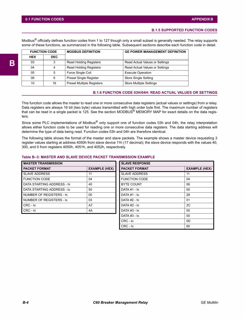
B-4 C60 Breaker Management Relay GE Multilin
0.1 FUNCTION CODES APPENDIX B
B
0.1 FUNCTION CODES B.1.5 SUPPORTED FUNCTION CODES
Modbus® officially defines function codes from 1 to 127 though only a small subset is generally needed. The relay supportssome of these functions, as summarized in the following table. Subsequent sections describe each function code in detail.
B.1.6 FUNCTION CODE 03H/04H: READ ACTUAL VALUES OR SETTINGS
This function code allows the master to read one or more consecutive data registers (actual values or settings) from a relay.Data registers are always 16 bit (two byte) values transmitted with high order byte first. The maximum number of registersthat can be read in a single packet is 125. See the section MODBUS® MEMORY MAP for exact details on the data regis-ters.
Since some PLC implementations of Modbus® only support one of function codes 03h and 04h, the relay interpretationallows either function code to be used for reading one or more consecutive data registers. The data starting address willdetermine the type of data being read. Function codes 03h and 04h are therefore identical.
The following table shows the format of the master and slave packets. The example shows a master device requesting 3register values starting at address 4050h from slave device 11h (17 decimal); the slave device responds with the values 40,300, and 0 from registers 4050h, 4051h, and 4052h, respectively.
FUNCTION CODE MODBUS DEFINITION GE POWER MANAGEMENT DEFINITIONHEX DEC03 3 Read Holding Registers Read Actual Values or Settings04 4 Read Holding Registers Read Actual Values or Settings05 5 Force Single Coil Execute Operation06 6 Preset Single Register Store Single Setting10 16 Preset Multiple Registers Store Multiple Settings
Table B3: MASTER AND SLAVE DEVICE PACKET TRANSMISSION EXAMPLEMASTER TRANSMISSION SLAVE RESPONSEPACKET FORMAT EXAMPLE (HEX) PACKET FORMAT EXAMPLE (HEX)SLAVE ADDRESS 11 SLAVE ADDRESS 11FUNCTION CODE 04 FUNCTION CODE 04DATA STARTING ADDRESS - hi 40 BYTE COUNT 06DATA STARTING ADDRESS - lo 50 DATA #1 - hi 00NUMBER OF REGISTERS - hi 00 DATA #1 - lo 28NUMBER OF REGISTERS - lo 03 DATA #2 - hi 01CRC - lo A7 DATA #2 - lo 2CCRC - hi 4A DATA #3 - hi 00
DATA #3 - lo 00CRC - lo 0DCRC - hi 60
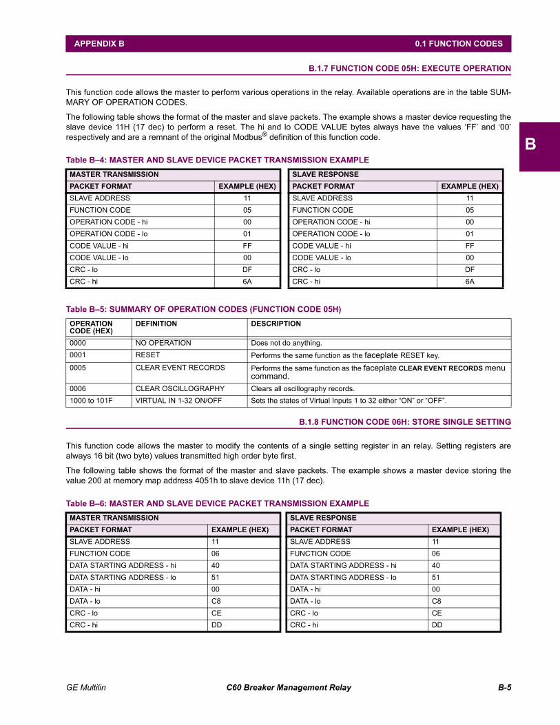
GE Multilin C60 Breaker Management Relay B-5
APPENDIX B 0.1 FUNCTION CODES
B
B.1.7 FUNCTION CODE 05H: EXECUTE OPERATION
This function code allows the master to perform various operations in the relay. Available operations are in the table SUM-MARY OF OPERATION CODES.
The following table shows the format of the master and slave packets. The example shows a master device requesting theslave device 11H (17 dec) to perform a reset. The hi and lo CODE VALUE bytes always have the values FF and 00respectively and are a remnant of the original Modbus® definition of this function code.
B.1.8 FUNCTION CODE 06H: STORE SINGLE SETTING
This function code allows the master to modify the contents of a single setting register in an relay. Setting registers arealways 16 bit (two byte) values transmitted high order byte first.
The following table shows the format of the master and slave packets. The example shows a master device storing thevalue 200 at memory map address 4051h to slave device 11h (17 dec).
Table B4: MASTER AND SLAVE DEVICE PACKET TRANSMISSION EXAMPLEMASTER TRANSMISSION SLAVE RESPONSEPACKET FORMAT EXAMPLE (HEX) PACKET FORMAT EXAMPLE (HEX)SLAVE ADDRESS 11 SLAVE ADDRESS 11FUNCTION CODE 05 FUNCTION CODE 05OPERATION CODE - hi 00 OPERATION CODE - hi 00OPERATION CODE - lo 01 OPERATION CODE - lo 01CODE VALUE - hi FF CODE VALUE - hi FFCODE VALUE - lo 00 CODE VALUE - lo 00CRC - lo DF CRC - lo DFCRC - hi 6A CRC - hi 6A
Table B5: SUMMARY OF OPERATION CODES (FUNCTION CODE 05H)OPERATION CODE (HEX)
DEFINITION DESCRIPTION
0000 NO OPERATION Does not do anything.0001 RESET Performs the same function as the faceplate RESET key.
0005 CLEAR EVENT RECORDS Performs the same function as the faceplate CLEAR EVENT RECORDS menu command.
0006 CLEAR OSCILLOGRAPHY Clears all oscillography records.1000 to 101F VIRTUAL IN 1-32 ON/OFF Sets the states of Virtual Inputs 1 to 32 either ON or OFF.
Table B6: MASTER AND SLAVE DEVICE PACKET TRANSMISSION EXAMPLEMASTER TRANSMISSION SLAVE RESPONSEPACKET FORMAT EXAMPLE (HEX) PACKET FORMAT EXAMPLE (HEX)SLAVE ADDRESS 11 SLAVE ADDRESS 11FUNCTION CODE 06 FUNCTION CODE 06DATA STARTING ADDRESS - hi 40 DATA STARTING ADDRESS - hi 40DATA STARTING ADDRESS - lo 51 DATA STARTING ADDRESS - lo 51DATA - hi 00 DATA - hi 00DATA - lo C8 DATA - lo C8CRC - lo CE CRC - lo CECRC - hi DD CRC - hi DD
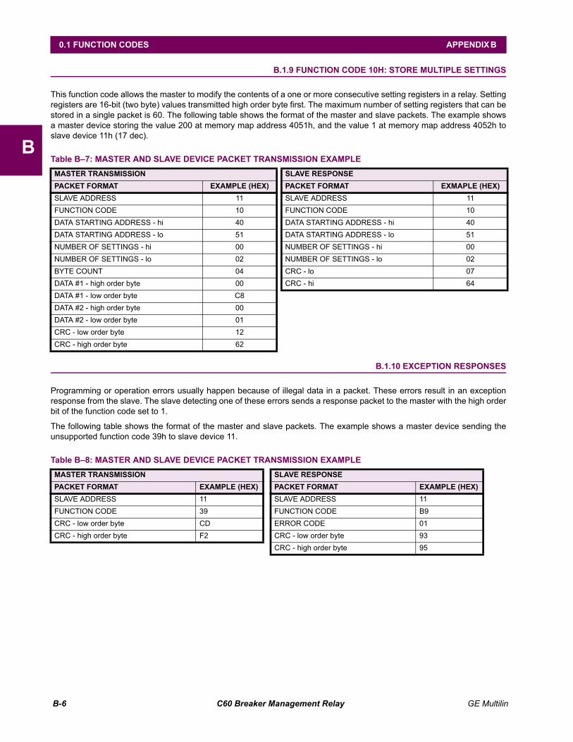
B-6 C60 Breaker Management Relay GE Multilin
0.1 FUNCTION CODES APPENDIX B
B
B.1.9 FUNCTION CODE 10H: STORE MULTIPLE SETTINGS
This function code allows the master to modify the contents of a one or more consecutive setting registers in a relay. Settingregisters are 16-bit (two byte) values transmitted high order byte first. The maximum number of setting registers that can bestored in a single packet is 60. The following table shows the format of the master and slave packets. The example showsa master device storing the value 200 at memory map address 4051h, and the value 1 at memory map address 4052h toslave device 11h (17 dec).
B.1.10 EXCEPTION RESPONSES
Programming or operation errors usually happen because of illegal data in a packet. These errors result in an exceptionresponse from the slave. The slave detecting one of these errors sends a response packet to the master with the high orderbit of the function code set to 1.
The following table shows the format of the master and slave packets. The example shows a master device sending theunsupported function code 39h to slave device 11.
Table B7: MASTER AND SLAVE DEVICE PACKET TRANSMISSION EXAMPLEMASTER TRANSMISSION SLAVE RESPONSEPACKET FORMAT EXAMPLE (HEX) PACKET FORMAT EXMAPLE (HEX)SLAVE ADDRESS 11 SLAVE ADDRESS 11FUNCTION CODE 10 FUNCTION CODE 10DATA STARTING ADDRESS - hi 40 DATA STARTING ADDRESS - hi 40DATA STARTING ADDRESS - lo 51 DATA STARTING ADDRESS - lo 51NUMBER OF SETTINGS - hi 00 NUMBER OF SETTINGS - hi 00NUMBER OF SETTINGS - lo 02 NUMBER OF SETTINGS - lo 02BYTE COUNT 04 CRC - lo 07DATA #1 - high order byte 00 CRC - hi 64DATA #1 - low order byte C8DATA #2 - high order byte 00DATA #2 - low order byte 01CRC - low order byte 12CRC - high order byte 62
Table B8: MASTER AND SLAVE DEVICE PACKET TRANSMISSION EXAMPLEMASTER TRANSMISSION SLAVE RESPONSEPACKET FORMAT EXAMPLE (HEX) PACKET FORMAT EXAMPLE (HEX)SLAVE ADDRESS 11 SLAVE ADDRESS 11FUNCTION CODE 39 FUNCTION CODE B9CRC - low order byte CD ERROR CODE 01CRC - high order byte F2 CRC - low order byte 93
CRC - high order byte 95
GE Multilin C60 Breaker Management Relay B-7
APPENDIX B B.2 FILE TRANSFERS
B
B.2 FILE TRANSFERS B.2.1 OBTAINING UR FILES USING MODBUS® PROTOCOL
The UR relay has a generic file transfer facility, meaning that you use the same method to obtain all of the different types offiles from the unit. The Modbus registers that implement file transfer are found in the "Modbus File Transfer (Read/Write)"and "Modbus File Transfer (Read Only)" modules, starting at address 3100 in the Modbus Memory Map. To read a file fromthe UR relay, use the following steps:
1. Write the filename to the "Name of file to read" register using a write multiple registers command. If the name is shorterthan 80 characters, you may write only enough registers to include all the text of the filename. Filenames are not casesensitive.
2. Repeatedly read all the registers in "Modbus File Transfer (Read Only)" using a read multiple registers command. It isnot necessary to read the entire data block, since the UR relay will remember which was the last register you read. The"position" register is initially zero and thereafter indicates how many bytes (2 times the number of registers) you haveread so far. The "size of..." register indicates the number of bytes of data remaining to read, to a maximum of 244.
3. Keep reading until the "size of..." register is smaller than the number of bytes you are transferring. This condition indi-cates end of file. Discard any bytes you have read beyond the indicated block size.
4. If you need to re-try a block, read only the "size of.." and "block of data", without reading the position. The file pointer isonly incremented when you read the position register, so the same data block will be returned as was read in the pre-vious operation. On the next read, check to see if the position is where you expect it to be, and discard the previousblock if it is not (this condition would indicate that the UR relay did not process your original read request).
The UR relay retains connection-specific file transfer information, so files may be read simultaneously on multiple Modbusconnections.
a) OBTAINING FILES FROM THE UR USING OTHER PROTOCOLS
All the files available via Modbus may also be retrieved using the standard file transfer mechanisms in other protocols (forexample, TFTP or MMS).
b) COMTRADE, OSCILLOGRAPHY AND DATA LOGGER FILES
Oscillography and data logger files are formatted using the COMTRADE file format per IEEE PC37.111 Draft 7c (02 Sep-tember 1997). The files may be obtained in either text or binary COMTRADE format.
c) READING OSCILLOGRAPHY FILES
Familiarity with the oscillography feature is required to understand the following description. Refer to the OSCILLOGRA-PHY section in the SETTINGS chapter for additional details.
The Oscillography_Number_of_Triggers register is incremented by one every time a new oscillography file is triggered(captured) and cleared to zero when oscillography data is cleared. When a new trigger occurs, the associated oscillographyfile is assigned a file identifier number equal to the incremented value of this register; the newest file number is equal to theOscillography_Number_of_Triggers register. This register can be used to determine if any new data has been captured byperiodically reading it to see if the value has changed; if the number has increased then new data is available.
The Oscillography_Number_of_Records setting specifies the maximum number of files (and the number of cycles of dataper file) that can be stored in memory of the relay. The Oscillography_Available_Records register specifies the actual num-ber of files that are stored and still available to be read out of the relay.
Writing Yes (i.e. the value 1) to the Oscillography_Clear_Data register clears oscillography data files, clears both theOscillography_Number_of_Triggers and Oscillography_Available_Records registers to zero, and sets theOscillography_Last_Cleared_Date to the present date and time.
To read binary COMTRADE oscillography files, read the following filenames:
OSCnnnn.CFG
OSCnnn.DAT
Replace "nnn" with the desired oscillography trigger number. For ASCII format, use the following file names
OSCAnnnn.CFG
OSCAnnn.DAT
B-8 C60 Breaker Management Relay GE Multilin
B.2 FILE TRANSFERS APPENDIX B
B
d) READING DATA LOGGER FILES
Familiarity with the data logger feature is required to understand this description. Refer to the DATA LOGGER section ofChapter 5 for details. To read the entire data logger in binary COMTRADE format, read the following files.
datalog.cfg
datalog.dat
To read the entire data logger in ASCII COMTRADE format, read the following files.
dataloga.cfg
dataloga.dat
To limit the range of records to be returned in the COMTRADE files, append the following to the filename before writing it:
To read from a specific time to the end of the log: <space> startTime
To read a specific range of records: <space> startTime <space> endTime
Replace <startTime> and <endTime> with Julian dates (seconds since Jan. 1 1970) as numeric text.
e) READING EVENT RECORDER FILES
To read the entire event recorder contents in ASCII format (the only available format), use the following filename:
EVT.TXT
To read from a specific record to the end of the log, use the following filename:
EVTnnn.TXT (replace "nnn" with the desired starting record number)
B.2.2 MODBUS® PASSWORD OPERATION
The COMMAND password is set up at memory location 4000. Storing a value of "0" removes COMMAND password protec-tion. When reading the password setting, the encrypted value (zero if no password is set) is returned. COMMAND securityis required to change the COMMAND password. Similarly, the SETTING password is set up at memory location 4002.These are the same settings and encrypted values found in the SETTINGS ! PRODUCT SETUP !" PASSWORD SECURITYmenu via the keypad. Enabling password security for the faceplate display will also enable it for Modbus, and vice-versa.
To gain COMMAND level security access, the COMMAND password must be entered at memory location 4008. To gainSETTING level security access, the SETTING password must be entered at memory location 400A. The entered SETTINGpassword must match the current SETTING password setting, or must be zero, to change settings or download firmware.
COMMAND and SETTING passwords each have a 30-minute timer. Each timer starts when you enter the particular pass-word, and is re-started whenever you use it. For example, writing a setting re-starts the SETTING password timer andwriting a command register or forcing a coil re-starts the COMMAND password timer. The value read at memory location4010 can be used to confirm whether a COMMAND password is enabled or disabled (0 for Disabled). The value read atmemory location 4011 can be used to confirm whether a SETTING password is enabled or disabled.
COMMAND or SETTING password security access is restricted to the particular port or particular TCP/IP connection onwhich the entry was made. Passwords must be entered when accessing the relay through other ports or connections, andthe passwords must be re-entered after disconnecting and re-connecting on TCP/IP.
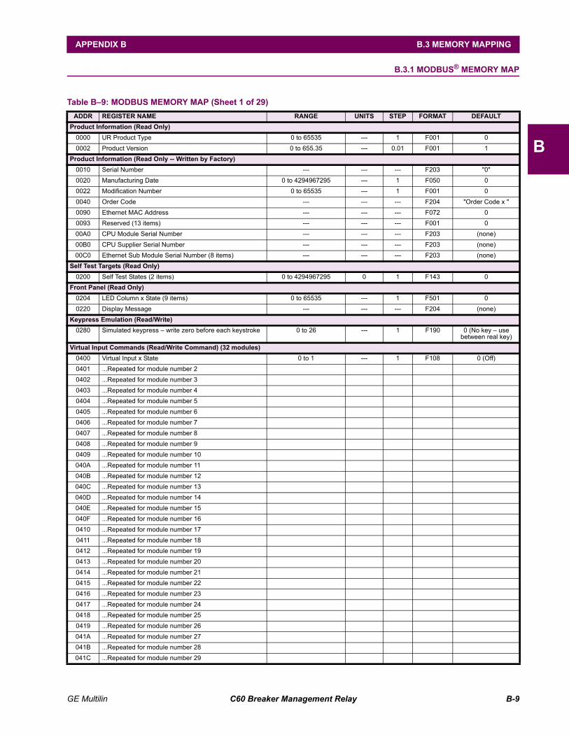
GE Multilin C60 Breaker Management Relay B-9
APPENDIX B B.3 MEMORY MAPPING
B
B.3 MEMORY MAPPING B.3.1 MODBUS® MEMORY MAP
Table B9: MODBUS MEMORY MAP (Sheet 1 of 29)ADDR REGISTER NAME RANGE UNITS STEP FORMAT DEFAULT
Product Information (Read Only)0000 UR Product Type 0 to 65535 --- 1 F001 0 0002 Product Version 0 to 655.35 --- 0.01 F001 1
Product Information (Read Only -- Written by Factory)0010 Serial Number --- --- --- F203 "0" 0020 Manufacturing Date 0 to 4294967295 --- 1 F050 0 0022 Modification Number 0 to 65535 --- 1 F001 0 0040 Order Code --- --- --- F204 "Order Code x " 0090 Ethernet MAC Address --- --- --- F072 0 0093 Reserved (13 items) --- --- --- F001 0 00A0 CPU Module Serial Number --- --- --- F203 (none) 00B0 CPU Supplier Serial Number --- --- --- F203 (none) 00C0 Ethernet Sub Module Serial Number (8 items) --- --- --- F203 (none)
Self Test Targets (Read Only)0200 Self Test States (2 items) 0 to 4294967295 0 1 F143 0
Front Panel (Read Only)0204 LED Column x State (9 items) 0 to 65535 --- 1 F501 0 0220 Display Message --- --- --- F204 (none)
Keypress Emulation (Read/Write)0280 Simulated keypress write zero before each keystroke 0 to 26 --- 1 F190 0 (No key use
between real key)Virtual Input Commands (Read/Write Command) (32 modules)
0400 Virtual Input x State 0 to 1 --- 1 F108 0 (Off) 0401 ...Repeated for module number 2 0402 ...Repeated for module number 3 0403 ...Repeated for module number 4 0404 ...Repeated for module number 5 0405 ...Repeated for module number 6 0406 ...Repeated for module number 7 0407 ...Repeated for module number 8 0408 ...Repeated for module number 9 0409 ...Repeated for module number 10 040A ...Repeated for module number 11 040B ...Repeated for module number 12 040C ...Repeated for module number 13 040D ...Repeated for module number 14 040E ...Repeated for module number 15 040F ...Repeated for module number 16 0410 ...Repeated for module number 17 0411 ...Repeated for module number 18 0412 ...Repeated for module number 19 0413 ...Repeated for module number 20 0414 ...Repeated for module number 21 0415 ...Repeated for module number 22 0416 ...Repeated for module number 23 0417 ...Repeated for module number 24 0418 ...Repeated for module number 25 0419 ...Repeated for module number 26 041A ...Repeated for module number 27 041B ...Repeated for module number 28 041C ...Repeated for module number 29
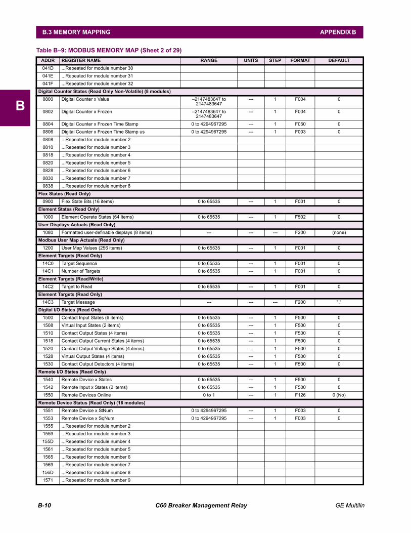
B-10 C60 Breaker Management Relay GE Multilin
B.3 MEMORY MAPPING APPENDIX B
B
041D ...Repeated for module number 30 041E ...Repeated for module number 31 041F ...Repeated for module number 32
Digital Counter States (Read Only Non-Volatile) (8 modules)0800 Digital Counter x Value 2147483647 to
2147483647--- 1 F004 0
0802 Digital Counter x Frozen 2147483647 to 2147483647
--- 1 F004 0
0804 Digital Counter x Frozen Time Stamp 0 to 4294967295 --- 1 F050 0 0806 Digital Counter x Frozen Time Stamp us 0 to 4294967295 --- 1 F003 0 0808 ...Repeated for module number 2 0810 ...Repeated for module number 3 0818 ...Repeated for module number 4 0820 ...Repeated for module number 5 0828 ...Repeated for module number 6 0830 ...Repeated for module number 7 0838 ...Repeated for module number 8
Flex States (Read Only)0900 Flex State Bits (16 items) 0 to 65535 --- 1 F001 0
Element States (Read Only)1000 Element Operate States (64 items) 0 to 65535 --- 1 F502 0
User Displays Actuals (Read Only)1080 Formatted user-definable displays (8 items) --- --- --- F200 (none)
Modbus User Map Actuals (Read Only)1200 User Map Values (256 items) 0 to 65535 --- 1 F001 0
Element Targets (Read Only)14C0 Target Sequence 0 to 65535 --- 1 F001 0 14C1 Number of Targets 0 to 65535 --- 1 F001 0
Element Targets (Read/Write)14C2 Target to Read 0 to 65535 --- 1 F001 0
Element Targets (Read Only)14C3 Target Message --- --- --- F200 "."
Digital I/O States (Read Only1500 Contact Input States (6 items) 0 to 65535 --- 1 F500 0 1508 Virtual Input States (2 items) 0 to 65535 --- 1 F500 0 1510 Contact Output States (4 items) 0 to 65535 --- 1 F500 0 1518 Contact Output Current States (4 items) 0 to 65535 --- 1 F500 0 1520 Contact Output Voltage States (4 items) 0 to 65535 --- 1 F500 0 1528 Virtual Output States (4 items) 0 to 65535 --- 1 F500 0 1530 Contact Output Detectors (4 items) 0 to 65535 --- 1 F500 0
Remote I/O States (Read Only)1540 Remote Device x States 0 to 65535 --- 1 F500 0 1542 Remote Input x States (2 items) 0 to 65535 --- 1 F500 0 1550 Remote Devices Online 0 to 1 --- 1 F126 0 (No)
Remote Device Status (Read Only) (16 modules)1551 Remote Device x StNum 0 to 4294967295 --- 1 F003 0 1553 Remote Device x SqNum 0 to 4294967295 --- 1 F003 0 1555 ...Repeated for module number 2 1559 ...Repeated for module number 3 155D ...Repeated for module number 4 1561 ...Repeated for module number 5 1565 ...Repeated for module number 6 1569 ...Repeated for module number 7 156D ...Repeated for module number 8 1571 ...Repeated for module number 9
Table B9: MODBUS MEMORY MAP (Sheet 2 of 29)ADDR REGISTER NAME RANGE UNITS STEP FORMAT DEFAULT

GE Multilin C60 Breaker Management Relay B-11
APPENDIX B B.3 MEMORY MAPPING
B
1575 ...Repeated for module number 10 1579 ...Repeated for module number 11 157D ...Repeated for module number 12 1581 ...Repeated for module number 13 1585 ...Repeated for module number 14 1589 ...Repeated for module number 15 158D ...Repeated for module number 16
Ethernet Fibre Channel Status (Read/Write)1610 Ethernet Primary Fibre Channel Status 0 to 2 --- 1 F134 0 (Fail) 1611 Ethernet Secondary Fibre Channel Status 0 to 2 --- 1 F134 0 (Fail)
Data Logger Actuals (Read Only)1618 Data Logger Channel Count 0 to 16 CHNL 1 F001 0 1619 Time of oldest available samples 0 to 4294967295 seconds 1 F050 0 161B Time of newest available samples 0 to 4294967295 seconds 1 F050 0 161D Data Logger Duration 0 to 999.9 DAYS 0.1 F001 0
Source Current (Read Only) (6 modules)1800 Phase A Current RMS 0 to 999999.999 A 0.001 F060 0 1802 Phase B Current RMS 0 to 999999.999 A 0.001 F060 0 1804 Phase C Current RMS 0 to 999999.999 A 0.001 F060 0 1806 Neutral Current RMS 0 to 999999.999 A 0.001 F060 0 1808 Phase A Current Magnitude 0 to 999999.999 A 0.001 F060 0 180A Phase A Current Angle -359.9 to 0 ° 0.1 F002 0 180B Phase B Current Magnitude 0 to 999999.999 A 0.001 F060 0 180D Phase B Current Angle -359.9 to 0 ° 0.1 F002 0 180E Phase C Current Magnitude 0 to 999999.999 A 0.001 F060 0 1810 Phase C Current Angle -359.9 to 0 ° 0.1 F002 0 1811 Neutral Current Magnitude 0 to 999999.999 A 0.001 F060 0 1813 Neutral Current Angle -359.9 to 0 ° 0.1 F002 0 1814 Ground Current RMS 0 to 999999.999 A 0.001 F060 0 1816 Ground Current Magnitude 0 to 999999.999 A 0.001 F060 0 1818 Ground Current Angle -359.9 to 0 ° 0.1 F002 0 1819 Zero Sequence Current Magnitude 0 to 999999.999 A 0.001 F060 0 181B Zero Sequence Current Angle -359.9 to 0 ° 0.1 F002 0 181C Positive Sequence Current Magnitude 0 to 999999.999 A 0.001 F060 0 181E Positive Sequence Current Angle -359.9 to 0 ° 0.1 F002 0 181F Negative Sequence Current Magnitude 0 to 999999.999 A 0.001 F060 0 1821 Negative Sequence Current Angle -359.9 to 0 ° 0.1 F002 0 1822 Differential Ground Current Magnitude 0 to 999999.999 A 0.001 F060 0 1824 Differential Ground Current Angle -359.9 to 0 ° 0.1 F002 0 1825 Reserved (27 items) --- --- --- F001 0 1840 ...Repeated for module number 2 1880 ...Repeated for module number 3 18C0 ...Repeated for module number 4 1900 ...Repeated for module number 5 1940 ...Repeated for module number 6
Source Voltage (Read Only) (6 modules)1A00 Phase AG Voltage RMS 0 to 999999.999 V 0.001 F060 0 1A02 Phase BG Voltage RMS 0 to 999999.999 V 0.001 F060 0 1A04 Phase CG Voltage RMS 0 to 999999.999 V 0.001 F060 0 1A06 Phase AG Voltage Magnitude 0 to 999999.999 V 0.001 F060 0 1A08 Phase AG Voltage Angle -359.9 to 0 ° 0.1 F002 0 1A09 Phase BG Voltage Magnitude 0 to 999999.999 V 0.001 F060 0 1A0B Phase BG Voltage Angle -359.9 to 0 ° 0.1 F002 0 1A0C Phase CG Voltage Magnitude 0 to 999999.999 V 0.001 F060 0
Table B9: MODBUS MEMORY MAP (Sheet 3 of 29)ADDR REGISTER NAME RANGE UNITS STEP FORMAT DEFAULT
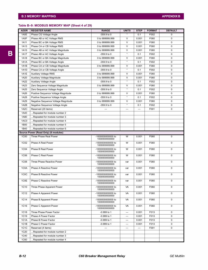
B-12 C60 Breaker Management Relay GE Multilin
B.3 MEMORY MAPPING APPENDIX B
B
1A0E Phase CG Voltage Angle -359.9 to 0 ° 0.1 F002 0 1A0F Phase AB or AC Voltage RMS 0 to 999999.999 V 0.001 F060 0 1A11 Phase BC or BA Voltage RMS 0 to 999999.999 V 0.001 F060 0 1A13 Phase CA or CB Voltage RMS 0 to 999999.999 V 0.001 F060 0 1A15 Phase AB or AC Voltage Magnitude 0 to 999999.999 V 0.001 F060 0 1A17 Phase AB or AC Voltage Angle -359.9 to 0 ° 0.1 F002 0 1A18 Phase BC or BA Voltage Magnitude 0 to 999999.999 V 0.001 F060 0 1A1A Phase BC or BA Voltage Angle -359.9 to 0 ° 0.1 F002 0 1A1B Phase CA or CB Voltage Magnitude 0 to 999999.999 V 0.001 F060 0 1A1D Phase CA or CB Voltage Angle -359.9 to 0 ° 0.1 F002 0 1A1E Auxiliary Voltage RMS 0 to 999999.999 V 0.001 F060 0 1A20 Auxiliary Voltage Magnitude 0 to 999999.999 V 0.001 F060 0 1A22 Auxiliary Voltage Angle -359.9 to 0 ° 0.1 F002 0 1A23 Zero Sequence Voltage Magnitude 0 to 999999.999 V 0.001 F060 0 1A25 Zero Sequence Voltage Angle -359.9 to 0 ° 0.1 F002 0 1A26 Positive Sequence Voltage Magnitude 0 to 999999.999 V 0.001 F060 0 1A28 Positive Sequence Voltage Angle -359.9 to 0 ° 0.1 F002 0 1A29 Negative Sequence Voltage Magnitude 0 to 999999.999 V 0.001 F060 0 1A2B Negative Sequence Voltage Angle -359.9 to 0 ° 0.1 F002 0 1A2C Reserved (20 items) --- --- --- F001 0 1A40 ...Repeated for module number 2 1A80 ...Repeated for module number 3 1AC0 ...Repeated for module number 4 1B00 ...Repeated for module number 5 1B40 ...Repeated for module number 6
Source Power (Read Only) (6 modules)1C00 Three Phase Real Power -1000000000000 to
1000000000000W 0.001 F060 0
1C02 Phase A Real Power -1000000000000 to 1000000000000
W 0.001 F060 0
1C04 Phase B Real Power -1000000000000 to 1000000000000
W 0.001 F060 0
1C06 Phase C Real Power -1000000000000 to 1000000000000
W 0.001 F060 0
1C08 Three Phase Reactive Power -1000000000000 to 1000000000000
var 0.001 F060 0
1C0A Phase A Reactive Power -1000000000000 to 1000000000000
var 0.001 F060 0
1C0C Phase B Reactive Power -1000000000000 to 1000000000000
var 0.001 F060 0
1C0E Phase C Reactive Power -1000000000000 to 1000000000000
var 0.001 F060 0
1C10 Three Phase Apparent Power -1000000000000 to 1000000000000
VA 0.001 F060 0
1C12 Phase A Apparent Power -1000000000000 to 1000000000000
VA 0.001 F060 0
1C14 Phase B Apparent Power -1000000000000 to 1000000000000
VA 0.001 F060 0
1C16 Phase C Apparent Power -1000000000000 to 1000000000000
VA 0.001 F060 0
1C18 Three Phase Power Factor -0.999 to 1 --- 0.001 F013 0 1C19 Phase A Power Factor -0.999 to 1 --- 0.001 F013 0 1C1A Phase B Power Factor -0.999 to 1 --- 0.001 F013 0 1C1B Phase C Power Factor -0.999 to 1 --- 0.001 F013 0 1C1C Reserved (4 items) --- --- --- F001 0 1C20 ...Repeated for module number 2 1C40 ...Repeated for module number 3 1C60 ...Repeated for module number 4
Table B9: MODBUS MEMORY MAP (Sheet 4 of 29)ADDR REGISTER NAME RANGE UNITS STEP FORMAT DEFAULT
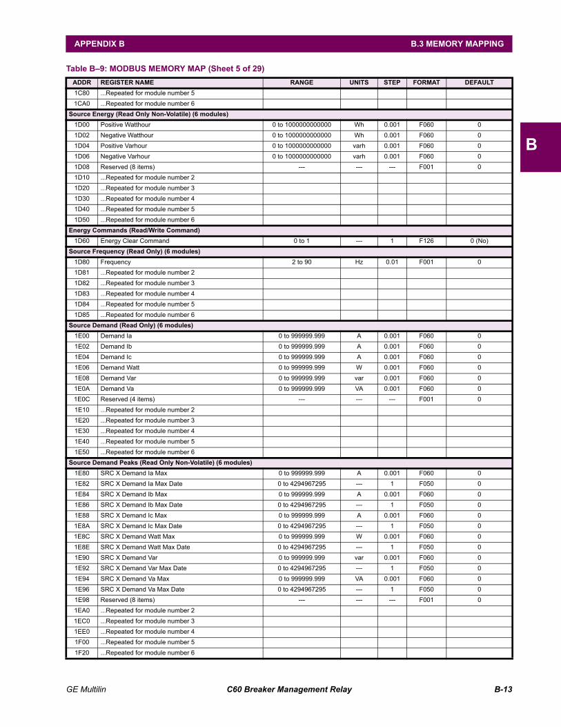
GE Multilin C60 Breaker Management Relay B-13
APPENDIX B B.3 MEMORY MAPPING
B
1C80 ...Repeated for module number 5 1CA0 ...Repeated for module number 6
Source Energy (Read Only Non-Volatile) (6 modules)1D00 Positive Watthour 0 to 1000000000000 Wh 0.001 F060 0 1D02 Negative Watthour 0 to 1000000000000 Wh 0.001 F060 0 1D04 Positive Varhour 0 to 1000000000000 varh 0.001 F060 0 1D06 Negative Varhour 0 to 1000000000000 varh 0.001 F060 0 1D08 Reserved (8 items) --- --- --- F001 0 1D10 ...Repeated for module number 2 1D20 ...Repeated for module number 3 1D30 ...Repeated for module number 4 1D40 ...Repeated for module number 5 1D50 ...Repeated for module number 6
Energy Commands (Read/Write Command)1D60 Energy Clear Command 0 to 1 --- 1 F126 0 (No)
Source Frequency (Read Only) (6 modules)1D80 Frequency 2 to 90 Hz 0.01 F001 0 1D81 ...Repeated for module number 2 1D82 ...Repeated for module number 3 1D83 ...Repeated for module number 4 1D84 ...Repeated for module number 5 1D85 ...Repeated for module number 6
Source Demand (Read Only) (6 modules)1E00 Demand Ia 0 to 999999.999 A 0.001 F060 0 1E02 Demand Ib 0 to 999999.999 A 0.001 F060 0 1E04 Demand Ic 0 to 999999.999 A 0.001 F060 0 1E06 Demand Watt 0 to 999999.999 W 0.001 F060 0 1E08 Demand Var 0 to 999999.999 var 0.001 F060 0 1E0A Demand Va 0 to 999999.999 VA 0.001 F060 0 1E0C Reserved (4 items) --- --- --- F001 0 1E10 ...Repeated for module number 2 1E20 ...Repeated for module number 3 1E30 ...Repeated for module number 4 1E40 ...Repeated for module number 5 1E50 ...Repeated for module number 6
Source Demand Peaks (Read Only Non-Volatile) (6 modules)1E80 SRC X Demand Ia Max 0 to 999999.999 A 0.001 F060 0 1E82 SRC X Demand Ia Max Date 0 to 4294967295 --- 1 F050 0 1E84 SRC X Demand Ib Max 0 to 999999.999 A 0.001 F060 0 1E86 SRC X Demand Ib Max Date 0 to 4294967295 --- 1 F050 0 1E88 SRC X Demand Ic Max 0 to 999999.999 A 0.001 F060 0 1E8A SRC X Demand Ic Max Date 0 to 4294967295 --- 1 F050 0 1E8C SRC X Demand Watt Max 0 to 999999.999 W 0.001 F060 0 1E8E SRC X Demand Watt Max Date 0 to 4294967295 --- 1 F050 0 1E90 SRC X Demand Var 0 to 999999.999 var 0.001 F060 0 1E92 SRC X Demand Var Max Date 0 to 4294967295 --- 1 F050 0 1E94 SRC X Demand Va Max 0 to 999999.999 VA 0.001 F060 0 1E96 SRC X Demand Va Max Date 0 to 4294967295 --- 1 F050 0 1E98 Reserved (8 items) --- --- --- F001 0 1EA0 ...Repeated for module number 2 1EC0 ...Repeated for module number 3 1EE0 ...Repeated for module number 4 1F00 ...Repeated for module number 5 1F20 ...Repeated for module number 6
Table B9: MODBUS MEMORY MAP (Sheet 5 of 29)ADDR REGISTER NAME RANGE UNITS STEP FORMAT DEFAULT
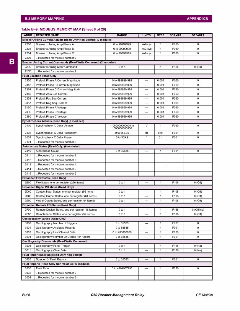
B-14 C60 Breaker Management Relay GE Multilin
B.3 MEMORY MAPPING APPENDIX B
B
Breaker Arcing Current Actuals (Read Only Non-Volatile) (2 modules)2200 Breaker x Arcing Amp Phase A 0 to 99999999 kA2-cyc 1 F060 0 2202 Breaker x Arcing Amp Phase B 0 to 99999999 kA2-cyc 1 F060 0 2204 Breaker x Arcing Amp Phase C 0 to 99999999 kA2-cyc 1 F060 0 2206 ...Repeated for module number 2
Breaker Arcing Current Commands (Read/Write Command) (2 modules)220C Breaker x Arcing Clear Command 0 to 1 --- 1 F126 0 (No) 220D ...Repeated for module number 2
Fault Location (Read Only)2350 Prefault Phase A Current Magnitude 0 to 999999.999 --- 0.001 F060 0 2352 Prefault Phase B Current Magnitude 0 to 999999.999 --- 0.001 F060 0 2354 Prefault Phase C Current Magnitude 0 to 999999.999 --- 0.001 F060 0 2356 Prefault Zero Seq Current 0 to 999999.999 --- 0.001 F060 0 2358 Prefault Pos Seq Current 0 to 999999.999 --- 0.001 F060 0 235A Prefault Neg Seq Current 0 to 999999.999 --- 0.001 F060 0 235C Prefault Phase A Voltage 0 to 999999.999 --- 0.001 F060 0 235E Prefault Phase B Voltage 0 to 999999.999 --- 0.001 F060 0 2360 Prefault Phase C Voltage 0 to 999999.999 --- 0.001 F060 0
Synchrocheck Actuals (Read Only) (2 modules)2400 Synchrocheck X Delta Voltage -1000000000000 to
1000000000000V 1 F060 0
2402 Synchrocheck X Delta Frequency 0 to 655.35 Hz 0.01 F001 0 2403 Synchrocheck X Delta Phase 0 to 359.9 ° 0.1 F001 0 2404 ...Repeated for module number 2
Autoreclose Status (Read Only) (6 modules)2410 Autoreclose Count 0 to 65535 --- 1 F001 0 2411 ...Repeated for module number 2 2412 ...Repeated for module number 3 2413 ...Repeated for module number 4 2414 ...Repeated for module number 5 2415 ...Repeated for module number 6
Expanded FlexStates (Read Only)2B00 FlexStates, one per register (256 items) 0 to 1 --- 1 F108 0 (Off)
Expanded Digital I/O states (Read Only)2D00 Contact Input States, one per register (96 items) 0 to 1 --- 1 F108 0 (Off) 2D80 Contact Output States, one per register (64 items) 0 to 1 --- 1 F108 0 (Off) 2E00 Virtual Output States, one per register (64 items) 0 to 1 --- 1 F108 0 (Off)
Expanded Remote I/O Status (Read Only)2F00 Remote Device States, one per register (16 items) 0 to 1 --- 1 F155 0 (Offline) 2F80 Remote Input States, one per register (32 items) 0 to 1 --- 1 F108 0 (Off)
Oscillography Values (Read Only)3000 Oscillography Number of Triggers 0 to 65535 --- 1 F001 0 3001 Oscillography Available Records 0 to 65535 --- 1 F001 0 3002 Oscillography Last Cleared Date 0 to 400000000 --- 1 F050 0 3004 Oscillography Number Of Cycles Per Record 0 to 65535 --- 1 F001 0
Oscillography Commands (Read/Write Command)3005 Oscillography Force Trigger 0 to 1 --- 1 F126 0 (No) 3011 Oscillography Clear Data 0 to 1 --- 1 F126 0 (No)
Fault Report Indexing (Read Only Non-Volatile)3020 Number Of Fault Reports 0 to 65535 --- 1 F001 0
Fault Reports (Read Only Non-Volatile) (10 modules)3030 Fault Time 0 to 4294967295 --- 1 F050 0 3032 ...Repeated for module number 2 3034 ...Repeated for module number 3
Table B9: MODBUS MEMORY MAP (Sheet 6 of 29)ADDR REGISTER NAME RANGE UNITS STEP FORMAT DEFAULT
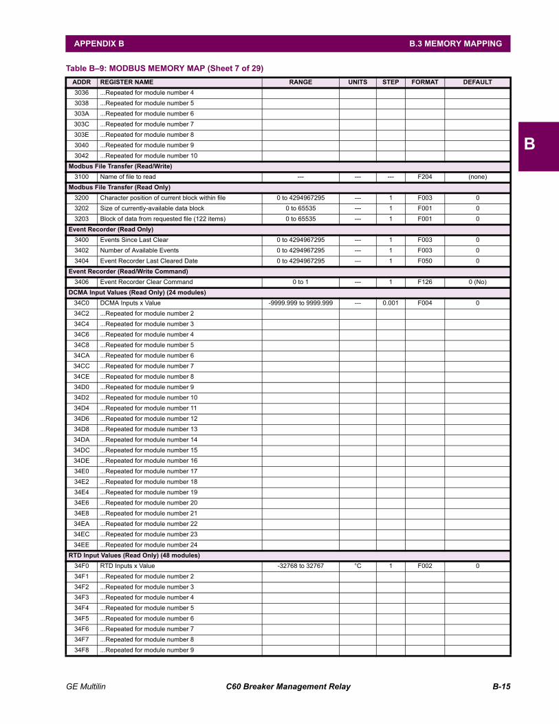
GE Multilin C60 Breaker Management Relay B-15
APPENDIX B B.3 MEMORY MAPPING
B
3036 ...Repeated for module number 4 3038 ...Repeated for module number 5 303A ...Repeated for module number 6 303C ...Repeated for module number 7 303E ...Repeated for module number 8 3040 ...Repeated for module number 9 3042 ...Repeated for module number 10
Modbus File Transfer (Read/Write)3100 Name of file to read --- --- --- F204 (none)
Modbus File Transfer (Read Only)3200 Character position of current block within file 0 to 4294967295 --- 1 F003 0 3202 Size of currently-available data block 0 to 65535 --- 1 F001 0 3203 Block of data from requested file (122 items) 0 to 65535 --- 1 F001 0
Event Recorder (Read Only)3400 Events Since Last Clear 0 to 4294967295 --- 1 F003 0 3402 Number of Available Events 0 to 4294967295 --- 1 F003 0 3404 Event Recorder Last Cleared Date 0 to 4294967295 --- 1 F050 0
Event Recorder (Read/Write Command)3406 Event Recorder Clear Command 0 to 1 --- 1 F126 0 (No)
DCMA Input Values (Read Only) (24 modules)34C0 DCMA Inputs x Value -9999.999 to 9999.999 --- 0.001 F004 0 34C2 ...Repeated for module number 2 34C4 ...Repeated for module number 3 34C6 ...Repeated for module number 4 34C8 ...Repeated for module number 5 34CA ...Repeated for module number 6 34CC ...Repeated for module number 7 34CE ...Repeated for module number 8 34D0 ...Repeated for module number 9 34D2 ...Repeated for module number 10 34D4 ...Repeated for module number 11 34D6 ...Repeated for module number 12 34D8 ...Repeated for module number 13 34DA ...Repeated for module number 14 34DC ...Repeated for module number 15 34DE ...Repeated for module number 16 34E0 ...Repeated for module number 17 34E2 ...Repeated for module number 18 34E4 ...Repeated for module number 19 34E6 ...Repeated for module number 20 34E8 ...Repeated for module number 21 34EA ...Repeated for module number 22 34EC ...Repeated for module number 23 34EE ...Repeated for module number 24
RTD Input Values (Read Only) (48 modules)34F0 RTD Inputs x Value -32768 to 32767 °C 1 F002 0 34F1 ...Repeated for module number 2 34F2 ...Repeated for module number 3 34F3 ...Repeated for module number 4 34F4 ...Repeated for module number 5 34F5 ...Repeated for module number 6 34F6 ...Repeated for module number 7 34F7 ...Repeated for module number 8 34F8 ...Repeated for module number 9
Table B9: MODBUS MEMORY MAP (Sheet 7 of 29)ADDR REGISTER NAME RANGE UNITS STEP FORMAT DEFAULT
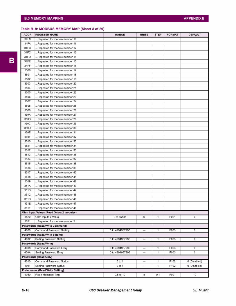
B-16 C60 Breaker Management Relay GE Multilin
B.3 MEMORY MAPPING APPENDIX B
B
34F9 ...Repeated for module number 10 34FA ...Repeated for module number 11 34FB ...Repeated for module number 12 34FC ...Repeated for module number 13 34FD ...Repeated for module number 14 34FE ...Repeated for module number 15 34FF ...Repeated for module number 16 3500 ...Repeated for module number 17 3501 ...Repeated for module number 18 3502 ...Repeated for module number 19 3503 ...Repeated for module number 20 3504 ...Repeated for module number 21 3505 ...Repeated for module number 22 3506 ...Repeated for module number 23 3507 ...Repeated for module number 24 3508 ...Repeated for module number 25 3509 ...Repeated for module number 26 350A ...Repeated for module number 27 350B ...Repeated for module number 28 350C ...Repeated for module number 29 350D ...Repeated for module number 30 350E ...Repeated for module number 31 350F ...Repeated for module number 32 3510 ...Repeated for module number 33 3511 ...Repeated for module number 34 3512 ...Repeated for module number 35 3513 ...Repeated for module number 36 3514 ...Repeated for module number 37 3515 ...Repeated for module number 38 3516 ...Repeated for module number 39 3517 ...Repeated for module number 40 3518 ...Repeated for module number 41 3519 ...Repeated for module number 42 351A ...Repeated for module number 43 351B ...Repeated for module number 44 351C ...Repeated for module number 45 351D ...Repeated for module number 46 351E ...Repeated for module number 47 351F ...Repeated for module number 48
Ohm Input Values (Read Only) (2 modules)3520 Ohm Inputs x Value 0 to 65535 Ω 1 F001 0 3521 ...Repeated for module number 2
Passwords (Read/Write Command)4000 Command Password Setting 0 to 4294967295 --- 1 F003 0
Passwords (Read/Write Setting)4002 Setting Password Setting 0 to 4294967295 --- 1 F003 0
Passwords (Read/Write)4008 Command Password Entry 0 to 4294967295 --- 1 F003 0 400A Setting Password Entry 0 to 4294967295 --- 1 F003 0
Passwords (Read Only)4010 Command Password Status 0 to 1 --- 1 F102 0 (Disabled) 4011 Setting Password Status 0 to 1 --- 1 F102 0 (Disabled)
Preferences (Read/Write Setting)4050 Flash Message Time 0.5 to 10 s 0.1 F001 10
Table B9: MODBUS MEMORY MAP (Sheet 8 of 29)ADDR REGISTER NAME RANGE UNITS STEP FORMAT DEFAULT
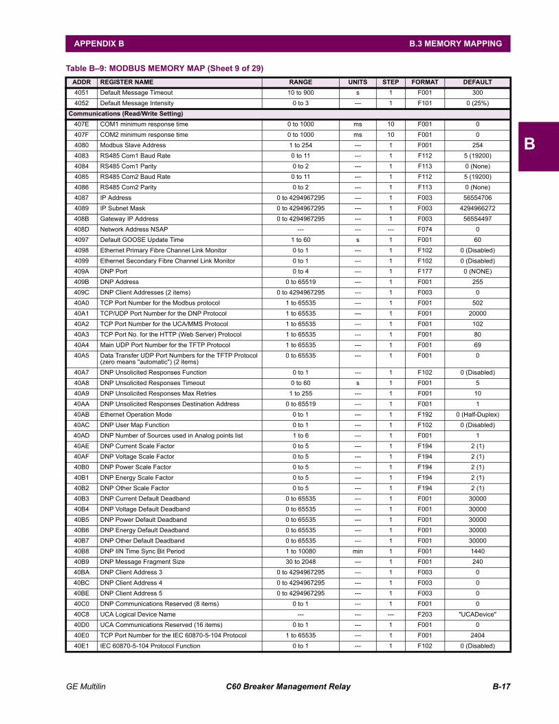
GE Multilin C60 Breaker Management Relay B-17
APPENDIX B B.3 MEMORY MAPPING
B
4051 Default Message Timeout 10 to 900 s 1 F001 300 4052 Default Message Intensity 0 to 3 --- 1 F101 0 (25%)
Communications (Read/Write Setting)407E COM1 minimum response time 0 to 1000 ms 10 F001 0 407F COM2 minimum response time 0 to 1000 ms 10 F001 0 4080 Modbus Slave Address 1 to 254 --- 1 F001 254 4083 RS485 Com1 Baud Rate 0 to 11 --- 1 F112 5 (19200) 4084 RS485 Com1 Parity 0 to 2 --- 1 F113 0 (None) 4085 RS485 Com2 Baud Rate 0 to 11 --- 1 F112 5 (19200) 4086 RS485 Com2 Parity 0 to 2 --- 1 F113 0 (None) 4087 IP Address 0 to 4294967295 --- 1 F003 56554706 4089 IP Subnet Mask 0 to 4294967295 --- 1 F003 4294966272 408B Gateway IP Address 0 to 4294967295 --- 1 F003 56554497 408D Network Address NSAP --- --- --- F074 0 4097 Default GOOSE Update Time 1 to 60 s 1 F001 60 4098 Ethernet Primary Fibre Channel Link Monitor 0 to 1 --- 1 F102 0 (Disabled) 4099 Ethernet Secondary Fibre Channel Link Monitor 0 to 1 --- 1 F102 0 (Disabled) 409A DNP Port 0 to 4 --- 1 F177 0 (NONE) 409B DNP Address 0 to 65519 --- 1 F001 255409C DNP Client Addresses (2 items) 0 to 4294967295 --- 1 F003 040A0 TCP Port Number for the Modbus protocol 1 to 65535 --- 1 F001 502 40A1 TCP/UDP Port Number for the DNP Protocol 1 to 65535 --- 1 F001 20000 40A2 TCP Port Number for the UCA/MMS Protocol 1 to 65535 --- 1 F001 102 40A3 TCP Port No. for the HTTP (Web Server) Protocol 1 to 65535 --- 1 F001 80 40A4 Main UDP Port Number for the TFTP Protocol 1 to 65535 --- 1 F001 69 40A5 Data Transfer UDP Port Numbers for the TFTP Protocol
(zero means "automatic") (2 items)0 to 65535 --- 1 F001 0
40A7 DNP Unsolicited Responses Function 0 to 1 --- 1 F102 0 (Disabled) 40A8 DNP Unsolicited Responses Timeout 0 to 60 s 1 F001 5 40A9 DNP Unsolicited Responses Max Retries 1 to 255 --- 1 F001 10 40AA DNP Unsolicited Responses Destination Address 0 to 65519 --- 1 F001 1 40AB Ethernet Operation Mode 0 to 1 --- 1 F192 0 (Half-Duplex) 40AC DNP User Map Function 0 to 1 --- 1 F102 0 (Disabled) 40AD DNP Number of Sources used in Analog points list 1 to 6 --- 1 F001 1 40AE DNP Current Scale Factor 0 to 5 --- 1 F194 2 (1) 40AF DNP Voltage Scale Factor 0 to 5 --- 1 F194 2 (1) 40B0 DNP Power Scale Factor 0 to 5 --- 1 F194 2 (1) 40B1 DNP Energy Scale Factor 0 to 5 --- 1 F194 2 (1) 40B2 DNP Other Scale Factor 0 to 5 --- 1 F194 2 (1) 40B3 DNP Current Default Deadband 0 to 65535 --- 1 F001 30000 40B4 DNP Voltage Default Deadband 0 to 65535 --- 1 F001 30000 40B5 DNP Power Default Deadband 0 to 65535 --- 1 F001 30000 40B6 DNP Energy Default Deadband 0 to 65535 --- 1 F001 30000 40B7 DNP Other Default Deadband 0 to 65535 --- 1 F001 30000 40B8 DNP IIN Time Sync Bit Period 1 to 10080 min 1 F001 1440 40B9 DNP Message Fragment Size 30 to 2048 --- 1 F001 240 40BA DNP Client Address 3 0 to 4294967295 --- 1 F003 0 40BC DNP Client Address 4 0 to 4294967295 --- 1 F003 0 40BE DNP Client Address 5 0 to 4294967295 --- 1 F003 0 40C0 DNP Communications Reserved (8 items) 0 to 1 --- 1 F001 0 40C8 UCA Logical Device Name --- --- --- F203 "UCADevice" 40D0 UCA Communications Reserved (16 items) 0 to 1 --- 1 F001 0 40E0 TCP Port Number for the IEC 60870-5-104 Protocol 1 to 65535 --- 1 F001 2404 40E1 IEC 60870-5-104 Protocol Function 0 to 1 --- 1 F102 0 (Disabled)
Table B9: MODBUS MEMORY MAP (Sheet 9 of 29)ADDR REGISTER NAME RANGE UNITS STEP FORMAT DEFAULT
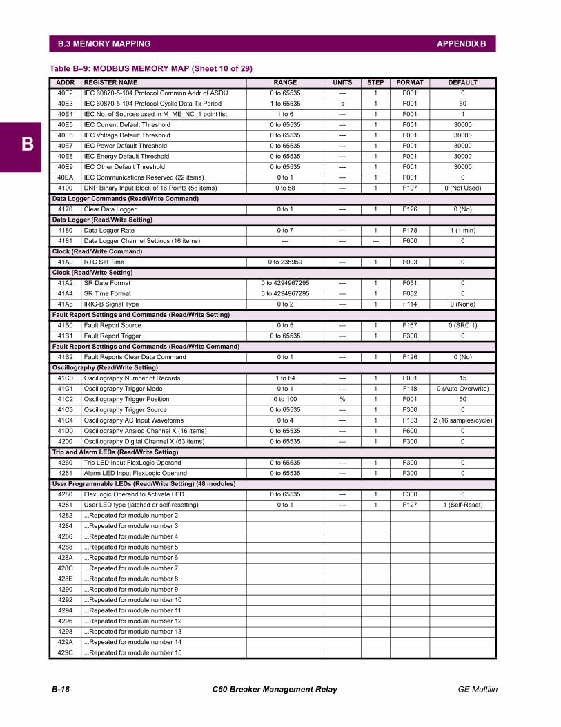
B-18 C60 Breaker Management Relay GE Multilin
B.3 MEMORY MAPPING APPENDIX B
B
40E2 IEC 60870-5-104 Protocol Common Addr of ASDU 0 to 65535 --- 1 F001 0 40E3 IEC 60870-5-104 Protocol Cyclic Data Tx Period 1 to 65535 s 1 F001 60 40E4 IEC No. of Sources used in M_ME_NC_1 point list 1 to 6 --- 1 F001 1 40E5 IEC Current Default Threshold 0 to 65535 --- 1 F001 30000 40E6 IEC Voltage Default Threshold 0 to 65535 --- 1 F001 30000 40E7 IEC Power Default Threshold 0 to 65535 --- 1 F001 30000 40E8 IEC Energy Default Threshold 0 to 65535 --- 1 F001 30000 40E9 IEC Other Default Threshold 0 to 65535 --- 1 F001 30000 40EA IEC Communications Reserved (22 items) 0 to 1 --- 1 F001 0 4100 DNP Binary Input Block of 16 Points (58 items) 0 to 58 --- 1 F197 0 (Not Used)
Data Logger Commands (Read/Write Command)4170 Clear Data Logger 0 to 1 --- 1 F126 0 (No)
Data Logger (Read/Write Setting)4180 Data Logger Rate 0 to 7 --- 1 F178 1 (1 min) 4181 Data Logger Channel Settings (16 items) --- --- --- F600 0
Clock (Read/Write Command)41A0 RTC Set Time 0 to 235959 --- 1 F003 0
Clock (Read/Write Setting)41A2 SR Date Format 0 to 4294967295 --- 1 F051 0 41A4 SR Time Format 0 to 4294967295 --- 1 F052 0 41A6 IRIG-B Signal Type 0 to 2 --- 1 F114 0 (None)
Fault Report Settings and Commands (Read/Write Setting)41B0 Fault Report Source 0 to 5 --- 1 F167 0 (SRC 1) 41B1 Fault Report Trigger 0 to 65535 --- 1 F300 0
Fault Report Settings and Commands (Read/Write Command)41B2 Fault Reports Clear Data Command 0 to 1 --- 1 F126 0 (No)
Oscillography (Read/Write Setting)41C0 Oscillography Number of Records 1 to 64 --- 1 F001 15 41C1 Oscillography Trigger Mode 0 to 1 --- 1 F118 0 (Auto Overwrite)41C2 Oscillography Trigger Position 0 to 100 % 1 F001 50 41C3 Oscillography Trigger Source 0 to 65535 --- 1 F300 0 41C4 Oscillography AC Input Waveforms 0 to 4 --- 1 F183 2 (16 samples/cycle) 41D0 Oscillography Analog Channel X (16 items) 0 to 65535 --- 1 F600 0 4200 Oscillography Digital Channel X (63 items) 0 to 65535 --- 1 F300 0
Trip and Alarm LEDs (Read/Write Setting)4260 Trip LED Input FlexLogic Operand 0 to 65535 --- 1 F300 0 4261 Alarm LED Input FlexLogic Operand 0 to 65535 --- 1 F300 0
User Programmable LEDs (Read/Write Setting) (48 modules)4280 FlexLogic Operand to Activate LED 0 to 65535 --- 1 F300 0 4281 User LED type (latched or self-resetting) 0 to 1 --- 1 F127 1 (Self-Reset) 4282 ...Repeated for module number 2 4284 ...Repeated for module number 3 4286 ...Repeated for module number 4 4288 ...Repeated for module number 5 428A ...Repeated for module number 6 428C ...Repeated for module number 7 428E ...Repeated for module number 8 4290 ...Repeated for module number 9 4292 ...Repeated for module number 10 4294 ...Repeated for module number 11 4296 ...Repeated for module number 12 4298 ...Repeated for module number 13 429A ...Repeated for module number 14 429C ...Repeated for module number 15
Table B9: MODBUS MEMORY MAP (Sheet 10 of 29)ADDR REGISTER NAME RANGE UNITS STEP FORMAT DEFAULT
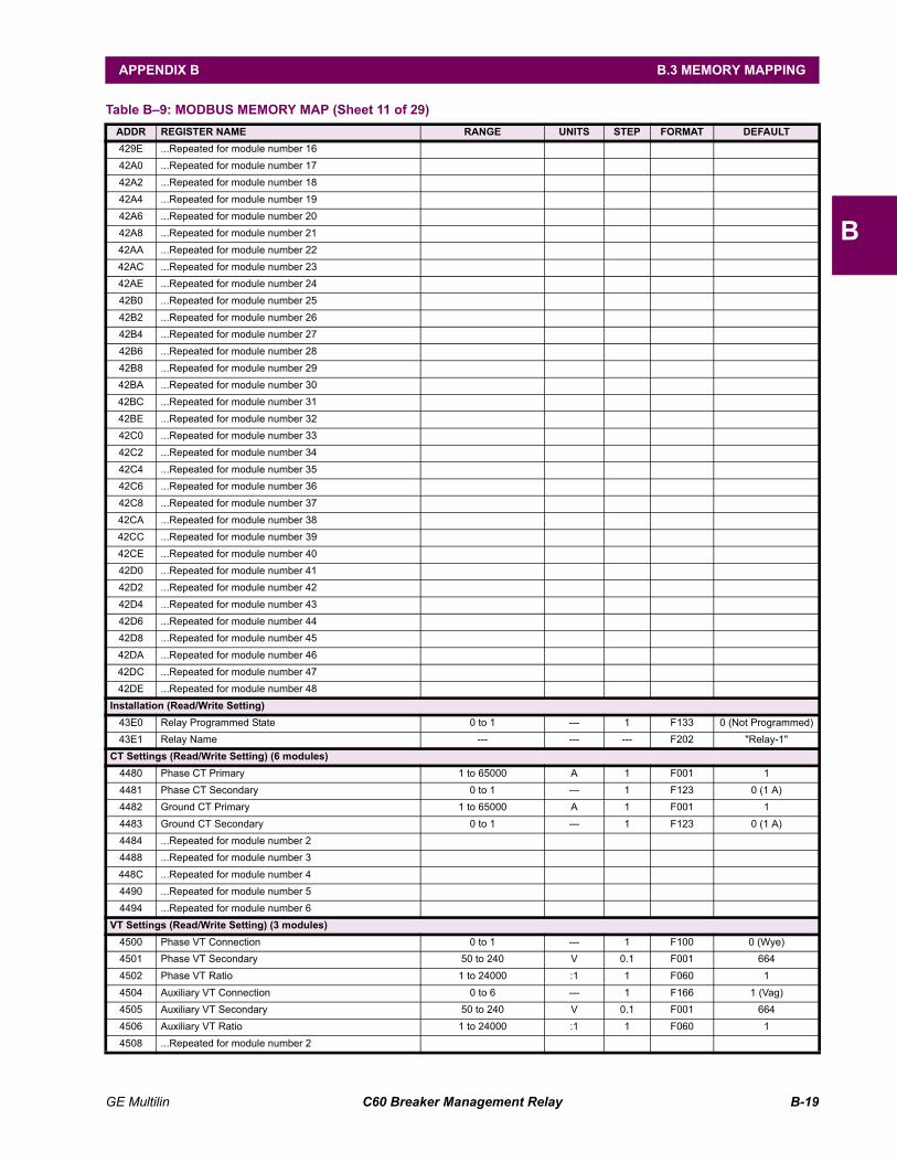
GE Multilin C60 Breaker Management Relay B-19
APPENDIX B B.3 MEMORY MAPPING
B
429E ...Repeated for module number 16 42A0 ...Repeated for module number 17 42A2 ...Repeated for module number 18 42A4 ...Repeated for module number 19 42A6 ...Repeated for module number 20 42A8 ...Repeated for module number 21 42AA ...Repeated for module number 22 42AC ...Repeated for module number 23 42AE ...Repeated for module number 24 42B0 ...Repeated for module number 25 42B2 ...Repeated for module number 26 42B4 ...Repeated for module number 27 42B6 ...Repeated for module number 28 42B8 ...Repeated for module number 29 42BA ...Repeated for module number 30 42BC ...Repeated for module number 31 42BE ...Repeated for module number 32 42C0 ...Repeated for module number 33 42C2 ...Repeated for module number 34 42C4 ...Repeated for module number 35 42C6 ...Repeated for module number 36 42C8 ...Repeated for module number 37 42CA ...Repeated for module number 38 42CC ...Repeated for module number 39 42CE ...Repeated for module number 40 42D0 ...Repeated for module number 41 42D2 ...Repeated for module number 42 42D4 ...Repeated for module number 43 42D6 ...Repeated for module number 44 42D8 ...Repeated for module number 45 42DA ...Repeated for module number 46 42DC ...Repeated for module number 47 42DE ...Repeated for module number 48
Installation (Read/Write Setting)43E0 Relay Programmed State 0 to 1 --- 1 F133 0 (Not Programmed) 43E1 Relay Name --- --- --- F202 "Relay-1"
CT Settings (Read/Write Setting) (6 modules)4480 Phase CT Primary 1 to 65000 A 1 F001 1 4481 Phase CT Secondary 0 to 1 --- 1 F123 0 (1 A) 4482 Ground CT Primary 1 to 65000 A 1 F001 1 4483 Ground CT Secondary 0 to 1 --- 1 F123 0 (1 A) 4484 ...Repeated for module number 2 4488 ...Repeated for module number 3 448C ...Repeated for module number 4 4490 ...Repeated for module number 5 4494 ...Repeated for module number 6
VT Settings (Read/Write Setting) (3 modules)4500 Phase VT Connection 0 to 1 --- 1 F100 0 (Wye) 4501 Phase VT Secondary 50 to 240 V 0.1 F001 664 4502 Phase VT Ratio 1 to 24000 :1 1 F060 1 4504 Auxiliary VT Connection 0 to 6 --- 1 F166 1 (Vag) 4505 Auxiliary VT Secondary 50 to 240 V 0.1 F001 664 4506 Auxiliary VT Ratio 1 to 24000 :1 1 F060 1 4508 ...Repeated for module number 2
Table B9: MODBUS MEMORY MAP (Sheet 11 of 29)ADDR REGISTER NAME RANGE UNITS STEP FORMAT DEFAULT
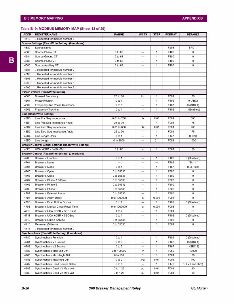
B-20 C60 Breaker Management Relay GE Multilin
B.3 MEMORY MAPPING APPENDIX B
B
4510 ...Repeated for module number 3Source Settings (Read/Write Setting) (6 modules)
4580 Source Name --- --- --- F206 "SRC 1 " 4583 Source Phase CT 0 to 63 --- 1 F400 0 4584 Source Ground CT 0 to 63 --- 1 F400 0 4585 Source Phase VT 0 to 63 --- 1 F400 0 4586 Source Auxiliary VT 0 to 63 --- 1 F400 0 4587 ...Repeated for module number 2 458E ...Repeated for module number 3 4595 ...Repeated for module number 4 459C ...Repeated for module number 5 45A3 ...Repeated for module number 6
Power System (Read/Write Setting)4600 Nominal Frequency 25 to 60 Hz 1 F001 60 4601 Phase Rotation 0 to 1 --- 1 F106 0 (ABC) 4602 Frequency And Phase Reference 0 to 5 --- 1 F167 0 (SRC 1) 4603 Frequency Tracking 0 to 1 --- 1 F102 1 (Enabled)
Line (Read/Write Setting)46D0 Line Pos Seq Impedance 0.01 to 250 Þ 0.01 F001 300 46D1 Line Pos Seq Impedance Angle 25 to 90 ° 1 F001 75 46D2 Line Zero Seq Impedance 0.01 to 650 Þ 0.01 F001 900 46D3 Line Zero Seq Impedance Angle 25 to 90 ° 1 F001 75 46D4 Line Length Units 0 to 1 --- 1 F147 0 (km) 46D5 Line Length 0 to 2000 --- 0.1 F001 1000
Breaker Control Global Settings (Read/Write Setting)46F0 UCA XCBR x SelTimOut 1 to 60 s 1 F001 30
Breaker Control (Read/Write Setting) (2 modules)4700 Breaker x Function 0 to 1 --- 1 F102 0 (Disabled) 4701 Breaker x Name --- --- --- F206 "Bkr 1 " 4704 Breaker x Mode 0 to 1 --- 1 F157 0 (3-Pole) 4705 Breaker x Open 0 to 65535 --- 1 F300 0 4706 Breaker x Close 0 to 65535 --- 1 F300 0 4707 Breaker x Phase A 3 Pole 0 to 65535 --- 1 F300 0 4708 Breaker x Phase B 0 to 65535 --- 1 F300 0 4709 Breaker x Phase C 0 to 65535 --- 1 F300 0 470A Breaker x External Alarm 0 to 65535 --- 1 F300 0 470B Breaker x Alarm Delay 0 to 1000000 s 0.001 F003 0 470D Breaker x Push Button Control 0 to 1 --- 1 F102 0 (Disabled) 470E Breaker x Manual Close Recal Time 0 to 1000000 s 0.001 F003 0 4710 Breaker x UCA XCBR x SBOClass 1 to 2 --- 1 F001 1 4711 Breaker x UCA XCBR x SBOEna 0 to 1 --- 1 F102 0 (Disabled) 4712 Breaker x Out Of Service 0 to 65535 --- 1 F300 0 4713 Reserved (5 items) 0 to 65535 1 F001 0 4718 ...Repeated for module number 2
Synchrocheck (Read/Write Setting) (2 modules)4780 Synchrocheck Function 0 to 1 --- 1 F102 0 (Disabled) 4781 Synchrocheck V1 Source 0 to 5 --- 1 F167 0 (SRC 1) 4782 Synchrocheck V2 Source 0 to 5 --- 1 F167 1 (SRC 2) 4783 Synchrocheck Max Volt Diff 0 to 100000 V 1 F060 10000 4785 Synchrocheck Max Angle Diff 0 to 100 ° 1 F001 30 4786 Synchrocheck Max Freq Diff 0 to 2 Hz 0.01 F001 100 4787 Synchrocheck Dead Source Select 0 to 5 --- 1 F176 1 (LV1 and DV2) 4788 Synchrocheck Dead V1 Max Volt 0 to 1.25 pu 0.01 F001 30 4789 Synchrocheck Dead V2 Max Volt 0 to 1.25 pu 0.01 F001 30
Table B9: MODBUS MEMORY MAP (Sheet 12 of 29)ADDR REGISTER NAME RANGE UNITS STEP FORMAT DEFAULT

GE Multilin C60 Breaker Management Relay B-21
APPENDIX B B.3 MEMORY MAPPING
B
478A Synchrocheck Live V1 Min Volt 0 to 1.25 pu 0.01 F001 70 478B Synchrocheck Live V2 Min Volt 0 to 1.25 pu 0.01 F001 70 478C Synchrocheck Target 0 to 2 --- 1 F109 0 (Self-reset) 478D Synchrocheck Events 0 to 1 --- 1 F102 0 (Disabled) 478E Synchrocheck Block 0 to 65535 --- 1 F300 0 478F Synchrocheck X Reserved 0 to 65535 --- 1 F001 0 4790 ...Repeated for module number 2
Modbus User Map (Read/Write Setting)4A00 Modbus Address Settings for User Map (256 items) 0 to 65535 --- 1 F001 0
User Displays Settings (Read/Write Setting) (8 modules)4C00 User display top line text --- --- --- F202 " " 4C0A User display bottom line text --- --- --- F202 " " 4C14 Modbus addresses of displayed items (5 items) 0 to 65535 --- 1 F001 0 4C19 Reserved (7 items) --- --- --- F001 0 4C20 ...Repeated for module number 24C40 ...Repeated for module number 34C60 ...Repeated for module number 44C80 ...Repeated for module number 54CA0 ...Repeated for module number 64CC0 ...Repeated for module number 74CE0 ...Repeated for module number 8
FlexLogic (Read/Write Setting)5000 FlexLogic Entry (512 items) 0 to 65535 --- 1 F300 16384
FlexLogic Timers (Read/Write Setting) (32 modules)5800 Timer x Type 0 to 2 --- 1 F129 0 (millisecond) 5801 Timer x Pickup Delay 0 to 60000 --- 1 F001 0 5802 Timer x Dropout Delay 0 to 60000 --- 1 F001 0 5803 Timer x Reserved (5 items) 0 to 65535 --- 1 F001 0 5808 ...Repeated for module number 2 5810 ...Repeated for module number 3 5818 ...Repeated for module number 4 5820 ...Repeated for module number 5 5828 ...Repeated for module number 6 5830 ...Repeated for module number 7 5838 ...Repeated for module number 8 5840 ...Repeated for module number 9 5848 ...Repeated for module number 10 5850 ...Repeated for module number 11 5858 ...Repeated for module number 12 5860 ...Repeated for module number 13 5868 ...Repeated for module number 14 5870 ...Repeated for module number 15 5878 ...Repeated for module number 16 5880 ...Repeated for module number 17 5888 ...Repeated for module number 18 5890 ...Repeated for module number 19 5898 ...Repeated for module number 20 58A0 ...Repeated for module number 21 58A8 ...Repeated for module number 22 58B0 ...Repeated for module number 23 58B8 ...Repeated for module number 24 58C0 ...Repeated for module number 25 58C8 ...Repeated for module number 26 58D0 ...Repeated for module number 27
Table B9: MODBUS MEMORY MAP (Sheet 13 of 29)ADDR REGISTER NAME RANGE UNITS STEP FORMAT DEFAULT
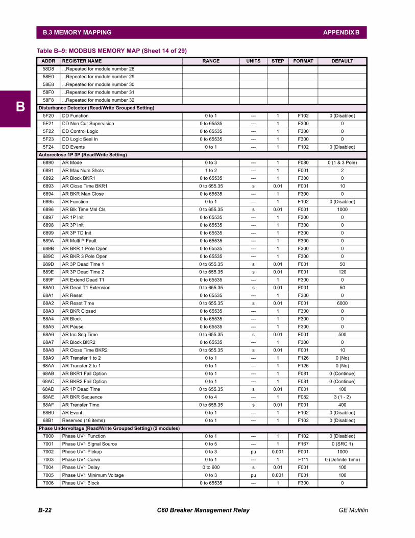
B-22 C60 Breaker Management Relay GE Multilin
B.3 MEMORY MAPPING APPENDIX B
B
58D8 ...Repeated for module number 28 58E0 ...Repeated for module number 29 58E8 ...Repeated for module number 30 58F0 ...Repeated for module number 31 58F8 ...Repeated for module number 32
Disturbance Detector (Read/Write Grouped Setting)5F20 DD Function 0 to 1 --- 1 F102 0 (Disabled) 5F21 DD Non Cur Supervision 0 to 65535 --- 1 F300 0 5F22 DD Control Logic 0 to 65535 --- 1 F300 0 5F23 DD Logic Seal In 0 to 65535 --- 1 F300 0 5F24 DD Events 0 to 1 --- 1 F102 0 (Disabled)
Autoreclose 1P 3P (Read/Write Setting)6890 AR Mode 0 to 3 --- 1 F080 0 (1 & 3 Pole) 6891 AR Max Num Shots 1 to 2 --- 1 F001 2 6892 AR Block BKR1 0 to 65535 --- 1 F300 0 6893 AR Close Time BKR1 0 to 655.35 s 0.01 F001 10 6894 AR BKR Man Close 0 to 65535 --- 1 F300 0 6895 AR Function 0 to 1 --- 1 F102 0 (Disabled) 6896 AR Blk Time Mnl Cls 0 to 655.35 s 0.01 F001 1000 6897 AR 1P Init 0 to 65535 --- 1 F300 0 6898 AR 3P Init 0 to 65535 --- 1 F300 0 6899 AR 3P TD Init 0 to 65535 --- 1 F300 0 689A AR Multi P Fault 0 to 65535 --- 1 F300 0 689B AR BKR 1 Pole Open 0 to 65535 --- 1 F300 0 689C AR BKR 3 Pole Open 0 to 65535 --- 1 F300 0 689D AR 3P Dead Time 1 0 to 655.35 s 0.01 F001 50 689E AR 3P Dead Time 2 0 to 655.35 s 0.01 F001 120 689F AR Extend Dead T1 0 to 65535 --- 1 F300 0 68A0 AR Dead T1 Extension 0 to 655.35 s 0.01 F001 50 68A1 AR Reset 0 to 65535 --- 1 F300 0 68A2 AR Reset Time 0 to 655.35 s 0.01 F001 6000 68A3 AR BKR Closed 0 to 65535 --- 1 F300 0 68A4 AR Block 0 to 65535 --- 1 F300 0 68A5 AR Pause 0 to 65535 --- 1 F300 0 68A6 AR Inc Seq Time 0 to 655.35 s 0.01 F001 500 68A7 AR Block BKR2 0 to 65535 --- 1 F300 0 68A8 AR Close Time BKR2 0 to 655.35 s 0.01 F001 10 68A9 AR Transfer 1 to 2 0 to 1 --- 1 F126 0 (No) 68AA AR Transfer 2 to 1 0 to 1 --- 1 F126 0 (No) 68AB AR BKR1 Fail Option 0 to 1 --- 1 F081 0 (Continue) 68AC AR BKR2 Fail Option 0 to 1 --- 1 F081 0 (Continue) 68AD AR 1P Dead Time 0 to 655.35 s 0.01 F001 100 68AE AR BKR Sequence 0 to 4 --- 1 F082 3 (1 - 2) 68AF AR Transfer Time 0 to 655.35 s 0.01 F001 400 68B0 AR Event 0 to 1 --- 1 F102 0 (Disabled) 68B1 Reserved (16 items) 0 to 1 --- 1 F102 0 (Disabled)
Phase Undervoltage (Read/Write Grouped Setting) (2 modules)7000 Phase UV1 Function 0 to 1 --- 1 F102 0 (Disabled) 7001 Phase UV1 Signal Source 0 to 5 --- 1 F167 0 (SRC 1) 7002 Phase UV1 Pickup 0 to 3 pu 0.001 F001 1000 7003 Phase UV1 Curve 0 to 1 --- 1 F111 0 (Definite Time) 7004 Phase UV1 Delay 0 to 600 s 0.01 F001 100 7005 Phase UV1 Minimum Voltage 0 to 3 pu 0.001 F001 100 7006 Phase UV1 Block 0 to 65535 --- 1 F300 0
Table B9: MODBUS MEMORY MAP (Sheet 14 of 29)ADDR REGISTER NAME RANGE UNITS STEP FORMAT DEFAULT
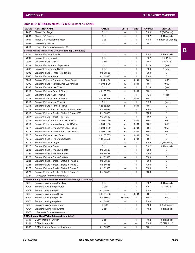
GE Multilin C60 Breaker Management Relay B-23
APPENDIX B B.3 MEMORY MAPPING
B
7007 Phase UV1 Target 0 to 2 --- 1 F109 0 (Self-reset) 7008 Phase UV1 Events 0 to 1 --- 1 F102 0 (Disabled) 7009 Phase UV Measurement Mode 0 to 1 --- 1 F186 0 (Phase to Ground) 700A Reserved (6 items) 0 to 1 --- 1 F001 0 7010 ...Repeated for module number 2
Breaker Failure (Read/Write Grouped Setting) (2 modules)7200 Breaker Failure x Function 0 to 1 --- 1 F102 0 (Disabled) 7201 Breaker Failure x Mode 0 to 1 --- 1 F157 0 (3-Pole) 7208 Breaker Failure x Source 0 to 5 --- 1 F167 0 (SRC 1) 7209 Breaker Failure x Amp Supervision 0 to 1 --- 1 F126 1 (Yes) 720A Breaker Failure x Use Seal-In 0 to 1 --- 1 F126 1 (Yes) 720B Breaker Failure x Three Pole Initiate 0 to 65535 --- 1 F300 0 720C Breaker Failure x Block 0 to 65535 --- 1 F300 0 720D Breaker Failure x Phase Amp Supv Pickup 0.001 to 30 pu 0.001 F001 1050 720E Breaker Failure x Neutral Amp Supv Pickup 0.001 to 30 pu 0.001 F001 1050 720F Breaker Failure x Use Timer 1 0 to 1 --- 1 F126 1 (Yes) 7210 Breaker Failure x Timer 1 Pickup 0 to 65.535 s 0.001 F001 0 7211 Breaker Failure x Use Timer 2 0 to 1 --- 1 F126 1 (Yes) 7212 Breaker Failure x Timer 2 Pickup 0 to 65.535 s 0.001 F001 0 7213 Breaker Failure x Use Timer 3 0 to 1 --- 1 F126 1 (Yes) 7214 Breaker Failure x Timer 3 Pickup 0 to 65.535 s 0.001 F001 0 7215 Breaker Failure x Breaker Status 1 Phase A/3P 0 to 65535 --- 1 F300 0 7216 Breaker Failure x Breaker Status 2 Phase A/3P 0 to 65535 --- 1 F300 0 7217 Breaker Failure x Breaker Test On 0 to 65535 --- 1 F300 0 7218 Breaker Failure x Phase Amp Hiset Pickup 0.001 to 30 pu 0.001 F001 1050 7219 Breaker Failure x Neutral Amp Hiset Pickup 0.001 to 30 pu 0.001 F001 1050 721A Breaker Failure x Phase Amp Loset Pickup 0.001 to 30 pu 0.001 F001 1050 721B Breaker Failure x Neutral Amp Loset Pickup 0.001 to 30 pu 0.001 F001 1050 721C Breaker Failure x Loset Time 0 to 65.535 s 0.001 F001 0 721D Breaker Failure x Trip Dropout Delay 0 to 65.535 s 0.001 F001 0 721E Breaker Failure x Target 0 to 2 --- 1 F109 0 (Self-reset) 721F Breaker Failure x Events 0 to 1 --- 1 F102 0 (Disabled) 7220 Breaker Failure x Phase A Initiate 0 to 65535 --- 1 F300 0 7221 Breaker Failure x Phase B Initiate 0 to 65535 --- 1 F300 0 7222 Breaker Failure x Phase C Initiate 0 to 65535 --- 1 F300 0 7223 Breaker Failure x Breaker Status 1 Phase B 0 to 65535 --- 1 F300 0 7224 Breaker Failure x Breaker Status 1 Phase C 0 to 65535 --- 1 F300 0 7225 Breaker Failure x Breaker Status 2 Phase B 0 to 65535 --- 1 F300 0 7226 Breaker Failure x Breaker Status 2 Phase C 0 to 65535 --- 1 F300 0 7227 ...Repeated for module number 2
Breaker Arcing Current Settings (Read/Write Setting) (2 modules)72C0 Breaker x Arcing Amp Function 0 to 1 --- 1 F102 0 (Disabled) 72C1 Breaker x Arcing Amp Source 0 to 5 --- 1 F167 0 (SRC 1) 72C2 Breaker x Arcing Amp Init 0 to 65535 --- 1 F300 0 72C3 Breaker x Arcing Amp Delay 0 to 65.535 s 0.001 F001 0 72C4 Breaker x Arcing Amp Limit 0 to 50000 kA2-cyc 1 F001 1000 72C5 Breaker x Arcing Amp Block 0 to 65535 --- 1 F300 0 72C6 Breaker x Arcing Amp Target 0 to 2 --- 1 F109 0 (Self-reset) 72C7 Breaker x Arcing Amp Events 0 to 1 --- 1 F102 0 (Disabled) 72C8 ...Repeated for module number 2
DCMA Inputs (Read/Write Setting) (24 modules)7300 DCMA Inputs x Function 0 to 1 --- 1 F102 0 (Disabled) 7301 DCMA Inputs x ID --- --- --- F205 "DCMA Ip 1 " 7307 DCMA Inputs x Reserved 1 (4 items) 0 to 65535 --- 1 F001 0
Table B9: MODBUS MEMORY MAP (Sheet 15 of 29)ADDR REGISTER NAME RANGE UNITS STEP FORMAT DEFAULT
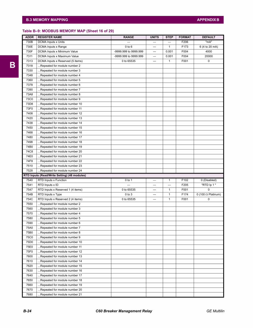
B-24 C60 Breaker Management Relay GE Multilin
B.3 MEMORY MAPPING APPENDIX B
B
730B DCMA Inputs x Units --- --- --- F206 "mA" 730E DCMA Inputs x Range 0 to 6 --- 1 F173 6 (4 to 20 mA) 730F DCMA Inputs x Minimum Value -9999.999 to 9999.999 --- 0.001 F004 4000 7311 DCMA Inputs x Maximum Value -9999.999 to 9999.999 --- 0.001 F004 20000 7313 DCMA Inputs x Reserved (5 items) 0 to 65535 --- 1 F001 0 7318 ...Repeated for module number 2 7330 ...Repeated for module number 3 7348 ...Repeated for module number 4 7360 ...Repeated for module number 5 7378 ...Repeated for module number 6 7390 ...Repeated for module number 7 73A8 ...Repeated for module number 8 73C0 ...Repeated for module number 9 73D8 ...Repeated for module number 10 73F0 ...Repeated for module number 11 7408 ...Repeated for module number 12 7420 ...Repeated for module number 13 7438 ...Repeated for module number 14 7450 ...Repeated for module number 15 7468 ...Repeated for module number 16 7480 ...Repeated for module number 17 7498 ...Repeated for module number 18 74B0 ...Repeated for module number 19 74C8 ...Repeated for module number 20 74E0 ...Repeated for module number 21 74F8 ...Repeated for module number 22 7510 ...Repeated for module number 23 7528 ...Repeated for module number 24
RTD Inputs (Read/Write Setting) (48 modules)7540 RTD Inputs x Function 0 to 1 --- 1 F102 0 (Disabled) 7541 RTD Inputs x ID --- --- --- F205 "RTD Ip 1 " 7547 RTD Inputs x Reserved 1 (4 items) 0 to 65535 --- 1 F001 0 754B RTD Inputs x Type 0 to 3 --- 1 F174 0 (100 Ω Platinum) 754C RTD Inputs x Reserved 2 (4 items) 0 to 65535 --- 1 F001 0 7550 ...Repeated for module number 2 7560 ...Repeated for module number 3 7570 ...Repeated for module number 4 7580 ...Repeated for module number 5 7590 ...Repeated for module number 6 75A0 ...Repeated for module number 7 75B0 ...Repeated for module number 8 75C0 ...Repeated for module number 9 75D0 ...Repeated for module number 10 75E0 ...Repeated for module number 11 75F0 ...Repeated for module number 12 7600 ...Repeated for module number 13 7610 ...Repeated for module number 14 7620 ...Repeated for module number 15 7630 ...Repeated for module number 16 7640 ...Repeated for module number 17 7650 ...Repeated for module number 18 7660 ...Repeated for module number 19 7670 ...Repeated for module number 20 7680 ...Repeated for module number 21
Table B9: MODBUS MEMORY MAP (Sheet 16 of 29)ADDR REGISTER NAME RANGE UNITS STEP FORMAT DEFAULT
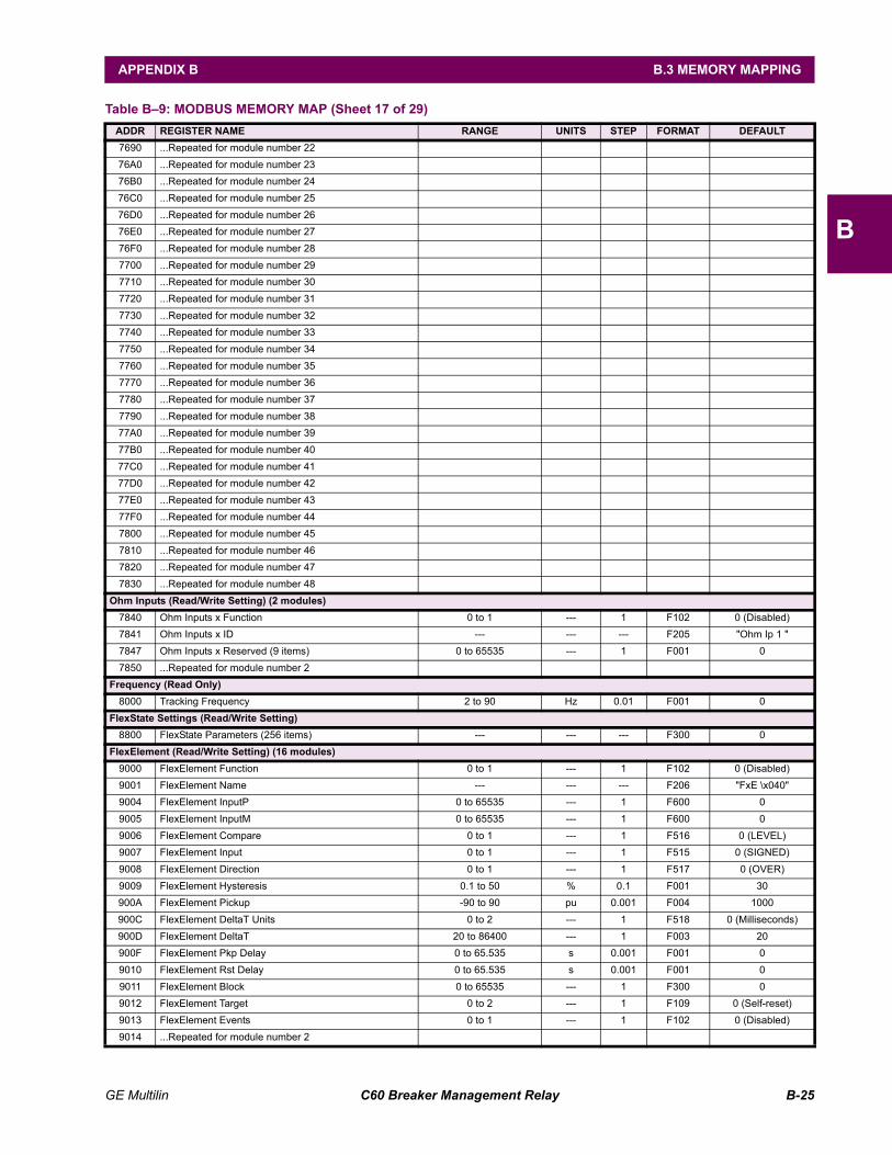
GE Multilin C60 Breaker Management Relay B-25
APPENDIX B B.3 MEMORY MAPPING
B
7690 ...Repeated for module number 22 76A0 ...Repeated for module number 23 76B0 ...Repeated for module number 24 76C0 ...Repeated for module number 25 76D0 ...Repeated for module number 26 76E0 ...Repeated for module number 27 76F0 ...Repeated for module number 28 7700 ...Repeated for module number 29 7710 ...Repeated for module number 30 7720 ...Repeated for module number 31 7730 ...Repeated for module number 32 7740 ...Repeated for module number 33 7750 ...Repeated for module number 34 7760 ...Repeated for module number 35 7770 ...Repeated for module number 36 7780 ...Repeated for module number 37 7790 ...Repeated for module number 38 77A0 ...Repeated for module number 39 77B0 ...Repeated for module number 40 77C0 ...Repeated for module number 41 77D0 ...Repeated for module number 42 77E0 ...Repeated for module number 43 77F0 ...Repeated for module number 44 7800 ...Repeated for module number 45 7810 ...Repeated for module number 46 7820 ...Repeated for module number 47 7830 ...Repeated for module number 48
Ohm Inputs (Read/Write Setting) (2 modules)7840 Ohm Inputs x Function 0 to 1 --- 1 F102 0 (Disabled) 7841 Ohm Inputs x ID --- --- --- F205 "Ohm Ip 1 " 7847 Ohm Inputs x Reserved (9 items) 0 to 65535 --- 1 F001 0 7850 ...Repeated for module number 2
Frequency (Read Only)8000 Tracking Frequency 2 to 90 Hz 0.01 F001 0
FlexState Settings (Read/Write Setting)8800 FlexState Parameters (256 items) --- --- --- F300 0
FlexElement (Read/Write Setting) (16 modules)9000 FlexElement Function 0 to 1 --- 1 F102 0 (Disabled) 9001 FlexElement Name --- --- --- F206 "FxE \x040" 9004 FlexElement InputP 0 to 65535 --- 1 F600 0 9005 FlexElement InputM 0 to 65535 --- 1 F600 0 9006 FlexElement Compare 0 to 1 --- 1 F516 0 (LEVEL) 9007 FlexElement Input 0 to 1 --- 1 F515 0 (SIGNED) 9008 FlexElement Direction 0 to 1 --- 1 F517 0 (OVER) 9009 FlexElement Hysteresis 0.1 to 50 % 0.1 F001 30 900A FlexElement Pickup -90 to 90 pu 0.001 F004 1000 900C FlexElement DeltaT Units 0 to 2 --- 1 F518 0 (Milliseconds) 900D FlexElement DeltaT 20 to 86400 --- 1 F003 20 900F FlexElement Pkp Delay 0 to 65.535 s 0.001 F001 0 9010 FlexElement Rst Delay 0 to 65.535 s 0.001 F001 0 9011 FlexElement Block 0 to 65535 --- 1 F300 0 9012 FlexElement Target 0 to 2 --- 1 F109 0 (Self-reset) 9013 FlexElement Events 0 to 1 --- 1 F102 0 (Disabled) 9014 ...Repeated for module number 2
Table B9: MODBUS MEMORY MAP (Sheet 17 of 29)ADDR REGISTER NAME RANGE UNITS STEP FORMAT DEFAULT
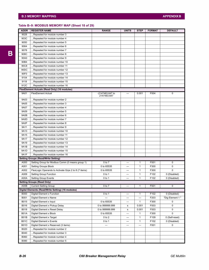
B-26 C60 Breaker Management Relay GE Multilin
B.3 MEMORY MAPPING APPENDIX B
B
9028 ...Repeated for module number 3 903C ...Repeated for module number 4 9050 ...Repeated for module number 5 9064 ...Repeated for module number 6 9078 ...Repeated for module number 7 908C ...Repeated for module number 8 90A0 ...Repeated for module number 9 90B4 ...Repeated for module number 10 90C8 ...Repeated for module number 11 90DC ...Repeated for module number 12 90F0 ...Repeated for module number 13 9104 ...Repeated for module number 14 9118 ...Repeated for module number 15 912C ...Repeated for module number 16
FlexElement Actuals (Read Only) (16 modules)9A01 FlexElement Actual -2147483.647 to
2147483.647--- 0.001 F004 0
9A03 ...Repeated for module number 2 9A05 ...Repeated for module number 3 9A07 ...Repeated for module number 4 9A09 ...Repeated for module number 5 9A0B ...Repeated for module number 6 9A0D ...Repeated for module number 7 9A0F ...Repeated for module number 8 9A11 ...Repeated for module number 9 9A13 ...Repeated for module number 10 9A15 ...Repeated for module number 11 9A17 ...Repeated for module number 12 9A19 ...Repeated for module number 13 9A1B ...Repeated for module number 14 9A1D ...Repeated for module number 15 9A1F ...Repeated for module number 16
Setting Groups (Read/Write Setting)A000 Setting Group for Modbus Comm (0 means group 1) 0 to 7 --- 1 F001 0 A001 Setting Groups Block 0 to 65535 --- 1 F300 0 A002 FlexLogic Operands to Activate Grps 2 to 8 (7 items) 0 to 65535 --- 1 F300 0 A009 Setting Group Function 0 to 1 --- 1 F102 0 (Disabled) A00A Setting Group Events 0 to 1 --- 1 F102 0 (Disabled)
Setting Groups (Read Only)A00B Current Setting Group 0 to 7 --- 1 F001 0
Digital Elements (Read/Write Setting) (16 modules)B000 Digital Element x Function 0 to 1 --- 1 F102 0 (Disabled) B001 Digital Element x Name --- --- --- F203 "Dig Element 1 " B015 Digital Element x Input 0 to 65535 --- 1 F300 0 B016 Digital Element x Pickup Delay 0 to 999999.999 s 0.001 F003 0 B018 Digital Element x Reset Delay 0 to 999999.999 s 0.001 F003 0 B01A Digital Element x Block 0 to 65535 --- 1 F300 0 B01B Digital Element x Target 0 to 2 --- 1 F109 0 (Self-reset) B01C Digital Element x Events 0 to 1 --- 1 F102 0 (Disabled) B01D Digital Element x Reserved (3 items) --- --- --- F001 0 B020 ...Repeated for module number 2 B040 ...Repeated for module number 3 B060 ...Repeated for module number 4 B080 ...Repeated for module number 5
Table B9: MODBUS MEMORY MAP (Sheet 18 of 29)ADDR REGISTER NAME RANGE UNITS STEP FORMAT DEFAULT
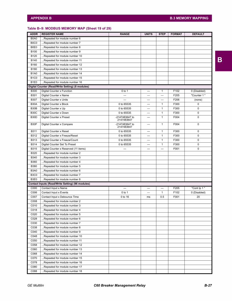
GE Multilin C60 Breaker Management Relay B-27
APPENDIX B B.3 MEMORY MAPPING
B
B0A0 ...Repeated for module number 6 B0C0 ...Repeated for module number 7 B0E0 ...Repeated for module number 8 B100 ...Repeated for module number 9 B120 ...Repeated for module number 10 B140 ...Repeated for module number 11 B160 ...Repeated for module number 12 B180 ...Repeated for module number 13 B1A0 ...Repeated for module number 14 B1C0 ...Repeated for module number 15 B1E0 ...Repeated for module number 16
Digital Counter (Read/Write Setting) (8 modules)B300 Digital Counter x Function 0 to 1 --- 1 F102 0 (Disabled) B301 Digital Counter x Name --- --- --- F205 "Counter 1 " B307 Digital Counter x Units --- --- --- F206 (none) B30A Digital Counter x Block 0 to 65535 --- 1 F300 0 B30B Digital Counter x Up 0 to 65535 --- 1 F300 0 B30C Digital Counter x Down 0 to 65535 --- 1 F300 0 B30D Digital Counter x Preset -2147483647 to
2147483647--- 1 F004 0
B30F Digital Counter x Compare -2147483647 to 2147483647
--- 1 F004 0
B311 Digital Counter x Reset 0 to 65535 --- 1 F300 0 B312 Digital Counter x Freeze/Reset 0 to 65535 --- 1 F300 0 B313 Digital Counter x Freeze/Count 0 to 65535 --- 1 F300 0 B314 Digital Counter Set To Preset 0 to 65535 --- 1 F300 0 B315 Digital Counter x Reserved (11 items) --- --- --- F001 0 B320 ...Repeated for module number 2 B340 ...Repeated for module number 3 B360 ...Repeated for module number 4 B380 ...Repeated for module number 5 B3A0 ...Repeated for module number 6 B3C0 ...Repeated for module number 7 B3E0 ...Repeated for module number 8
Contact Inputs (Read/Write Setting) (96 modules)C000 Contact Input x Name --- --- --- F205 "Cont Ip 1 " C006 Contact Input x Events 0 to 1 --- 1 F102 0 (Disabled) C007 Contact Input x Debounce Time 0 to 16 ms 0.5 F001 20 C008 ...Repeated for module number 2 C010 ...Repeated for module number 3 C018 ...Repeated for module number 4 C020 ...Repeated for module number 5 C028 ...Repeated for module number 6 C030 ...Repeated for module number 7 C038 ...Repeated for module number 8 C040 ...Repeated for module number 9 C048 ...Repeated for module number 10 C050 ...Repeated for module number 11 C058 ...Repeated for module number 12 C060 ...Repeated for module number 13 C068 ...Repeated for module number 14 C070 ...Repeated for module number 15 C078 ...Repeated for module number 16 C080 ...Repeated for module number 17 C088 ...Repeated for module number 18
Table B9: MODBUS MEMORY MAP (Sheet 19 of 29)ADDR REGISTER NAME RANGE UNITS STEP FORMAT DEFAULT
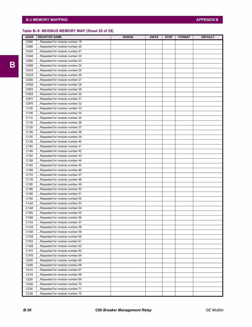
B-28 C60 Breaker Management Relay GE Multilin
B.3 MEMORY MAPPING APPENDIX B
B
C090 ...Repeated for module number 19 C098 ...Repeated for module number 20 C0A0 ...Repeated for module number 21 C0A8 ...Repeated for module number 22 C0B0 ...Repeated for module number 23 C0B8 ...Repeated for module number 24 C0C0 ...Repeated for module number 25 C0C8 ...Repeated for module number 26 C0D0 ...Repeated for module number 27 C0D8 ...Repeated for module number 28 C0E0 ...Repeated for module number 29 C0E8 ...Repeated for module number 30 C0F0 ...Repeated for module number 31 C0F8 ...Repeated for module number 32 C100 ...Repeated for module number 33 C108 ...Repeated for module number 34 C110 ...Repeated for module number 35 C118 ...Repeated for module number 36 C120 ...Repeated for module number 37 C128 ...Repeated for module number 38 C130 ...Repeated for module number 39 C138 ...Repeated for module number 40 C140 ...Repeated for module number 41 C148 ...Repeated for module number 42 C150 ...Repeated for module number 43 C158 ...Repeated for module number 44 C160 ...Repeated for module number 45 C168 ...Repeated for module number 46 C170 ...Repeated for module number 47 C178 ...Repeated for module number 48 C180 ...Repeated for module number 49 C188 ...Repeated for module number 50 C190 ...Repeated for module number 51 C198 ...Repeated for module number 52 C1A0 ...Repeated for module number 53 C1A8 ...Repeated for module number 54 C1B0 ...Repeated for module number 55 C1B8 ...Repeated for module number 56 C1C0 ...Repeated for module number 57 C1C8 ...Repeated for module number 58 C1D0 ...Repeated for module number 59 C1D8 ...Repeated for module number 60 C1E0 ...Repeated for module number 61 C1E8 ...Repeated for module number 62 C1F0 ...Repeated for module number 63 C1F8 ...Repeated for module number 64 C200 ...Repeated for module number 65 C208 ...Repeated for module number 66 C210 ...Repeated for module number 67 C218 ...Repeated for module number 68 C220 ...Repeated for module number 69 C228 ...Repeated for module number 70 C230 ...Repeated for module number 71 C238 ...Repeated for module number 72
Table B9: MODBUS MEMORY MAP (Sheet 20 of 29)ADDR REGISTER NAME RANGE UNITS STEP FORMAT DEFAULT
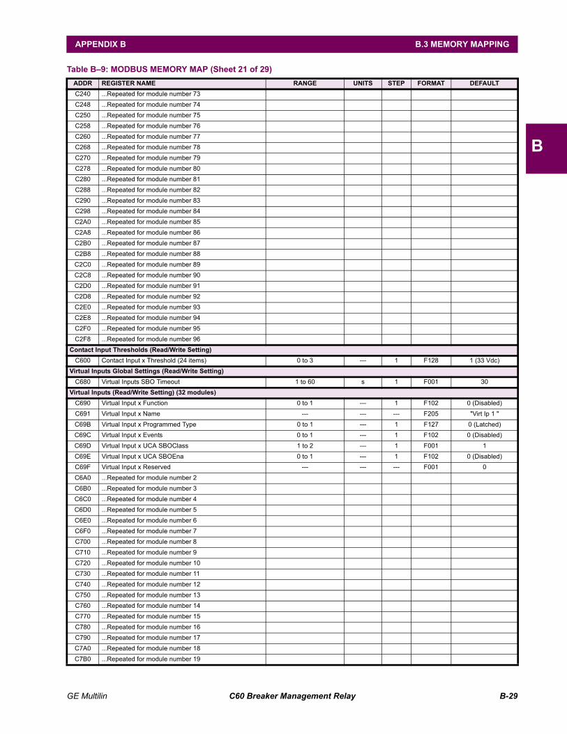
GE Multilin C60 Breaker Management Relay B-29
APPENDIX B B.3 MEMORY MAPPING
B
C240 ...Repeated for module number 73 C248 ...Repeated for module number 74 C250 ...Repeated for module number 75 C258 ...Repeated for module number 76 C260 ...Repeated for module number 77 C268 ...Repeated for module number 78 C270 ...Repeated for module number 79 C278 ...Repeated for module number 80 C280 ...Repeated for module number 81 C288 ...Repeated for module number 82 C290 ...Repeated for module number 83 C298 ...Repeated for module number 84 C2A0 ...Repeated for module number 85 C2A8 ...Repeated for module number 86 C2B0 ...Repeated for module number 87 C2B8 ...Repeated for module number 88 C2C0 ...Repeated for module number 89 C2C8 ...Repeated for module number 90 C2D0 ...Repeated for module number 91 C2D8 ...Repeated for module number 92 C2E0 ...Repeated for module number 93 C2E8 ...Repeated for module number 94 C2F0 ...Repeated for module number 95 C2F8 ...Repeated for module number 96
Contact Input Thresholds (Read/Write Setting)C600 Contact Input x Threshold (24 items) 0 to 3 --- 1 F128 1 (33 Vdc)
Virtual Inputs Global Settings (Read/Write Setting)C680 Virtual Inputs SBO Timeout 1 to 60 s 1 F001 30
Virtual Inputs (Read/Write Setting) (32 modules)C690 Virtual Input x Function 0 to 1 --- 1 F102 0 (Disabled) C691 Virtual Input x Name --- --- --- F205 "Virt Ip 1 " C69B Virtual Input x Programmed Type 0 to 1 --- 1 F127 0 (Latched) C69C Virtual Input x Events 0 to 1 --- 1 F102 0 (Disabled) C69D Virtual Input x UCA SBOClass 1 to 2 --- 1 F001 1 C69E Virtual Input x UCA SBOEna 0 to 1 --- 1 F102 0 (Disabled) C69F Virtual Input x Reserved --- --- --- F001 0 C6A0 ...Repeated for module number 2 C6B0 ...Repeated for module number 3 C6C0 ...Repeated for module number 4 C6D0 ...Repeated for module number 5 C6E0 ...Repeated for module number 6 C6F0 ...Repeated for module number 7 C700 ...Repeated for module number 8 C710 ...Repeated for module number 9 C720 ...Repeated for module number 10 C730 ...Repeated for module number 11 C740 ...Repeated for module number 12 C750 ...Repeated for module number 13 C760 ...Repeated for module number 14 C770 ...Repeated for module number 15 C780 ...Repeated for module number 16 C790 ...Repeated for module number 17 C7A0 ...Repeated for module number 18 C7B0 ...Repeated for module number 19
Table B9: MODBUS MEMORY MAP (Sheet 21 of 29)ADDR REGISTER NAME RANGE UNITS STEP FORMAT DEFAULT
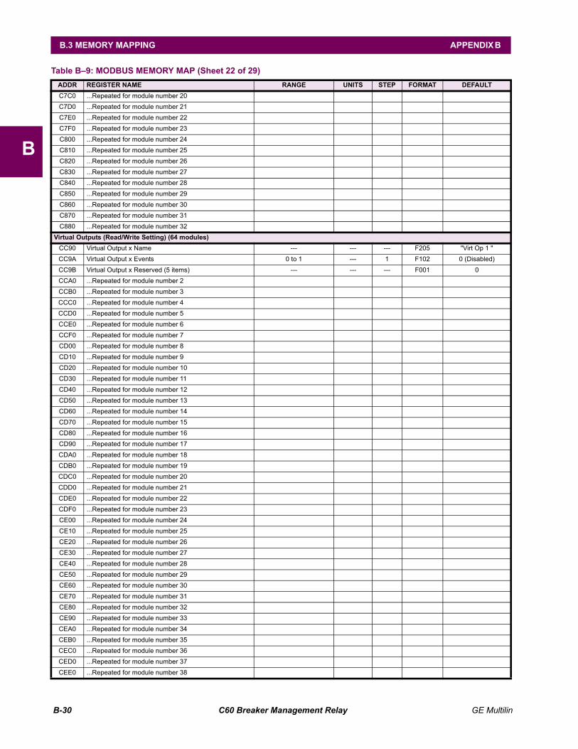
B-30 C60 Breaker Management Relay GE Multilin
B.3 MEMORY MAPPING APPENDIX B
B
C7C0 ...Repeated for module number 20 C7D0 ...Repeated for module number 21 C7E0 ...Repeated for module number 22 C7F0 ...Repeated for module number 23 C800 ...Repeated for module number 24 C810 ...Repeated for module number 25 C820 ...Repeated for module number 26 C830 ...Repeated for module number 27 C840 ...Repeated for module number 28 C850 ...Repeated for module number 29 C860 ...Repeated for module number 30 C870 ...Repeated for module number 31 C880 ...Repeated for module number 32
Virtual Outputs (Read/Write Setting) (64 modules)CC90 Virtual Output x Name --- --- --- F205 "Virt Op 1 " CC9A Virtual Output x Events 0 to 1 --- 1 F102 0 (Disabled) CC9B Virtual Output x Reserved (5 items) --- --- --- F001 0 CCA0 ...Repeated for module number 2 CCB0 ...Repeated for module number 3 CCC0 ...Repeated for module number 4 CCD0 ...Repeated for module number 5 CCE0 ...Repeated for module number 6 CCF0 ...Repeated for module number 7 CD00 ...Repeated for module number 8 CD10 ...Repeated for module number 9 CD20 ...Repeated for module number 10 CD30 ...Repeated for module number 11 CD40 ...Repeated for module number 12 CD50 ...Repeated for module number 13 CD60 ...Repeated for module number 14 CD70 ...Repeated for module number 15 CD80 ...Repeated for module number 16 CD90 ...Repeated for module number 17 CDA0 ...Repeated for module number 18 CDB0 ...Repeated for module number 19 CDC0 ...Repeated for module number 20 CDD0 ...Repeated for module number 21 CDE0 ...Repeated for module number 22 CDF0 ...Repeated for module number 23 CE00 ...Repeated for module number 24 CE10 ...Repeated for module number 25 CE20 ...Repeated for module number 26 CE30 ...Repeated for module number 27 CE40 ...Repeated for module number 28 CE50 ...Repeated for module number 29 CE60 ...Repeated for module number 30 CE70 ...Repeated for module number 31 CE80 ...Repeated for module number 32 CE90 ...Repeated for module number 33 CEA0 ...Repeated for module number 34 CEB0 ...Repeated for module number 35 CEC0 ...Repeated for module number 36 CED0 ...Repeated for module number 37 CEE0 ...Repeated for module number 38
Table B9: MODBUS MEMORY MAP (Sheet 22 of 29)ADDR REGISTER NAME RANGE UNITS STEP FORMAT DEFAULT
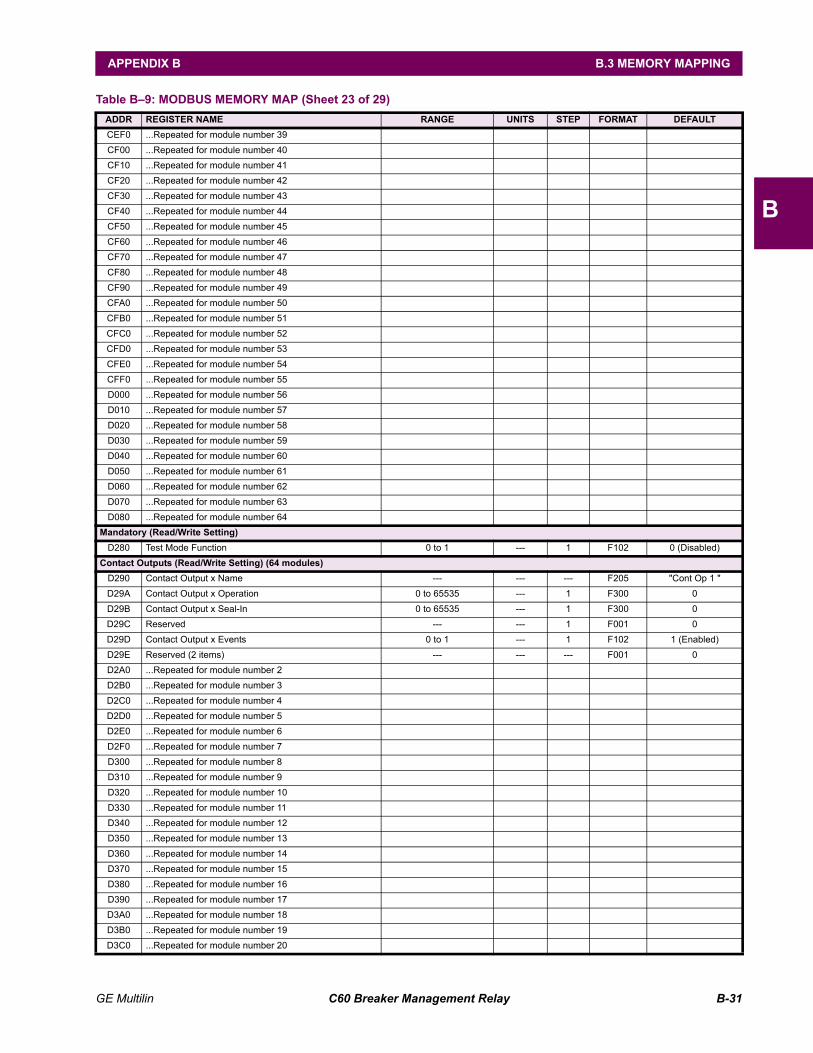
GE Multilin C60 Breaker Management Relay B-31
APPENDIX B B.3 MEMORY MAPPING
B
CEF0 ...Repeated for module number 39 CF00 ...Repeated for module number 40 CF10 ...Repeated for module number 41 CF20 ...Repeated for module number 42 CF30 ...Repeated for module number 43 CF40 ...Repeated for module number 44 CF50 ...Repeated for module number 45 CF60 ...Repeated for module number 46 CF70 ...Repeated for module number 47 CF80 ...Repeated for module number 48 CF90 ...Repeated for module number 49 CFA0 ...Repeated for module number 50 CFB0 ...Repeated for module number 51 CFC0 ...Repeated for module number 52 CFD0 ...Repeated for module number 53 CFE0 ...Repeated for module number 54 CFF0 ...Repeated for module number 55 D000 ...Repeated for module number 56 D010 ...Repeated for module number 57 D020 ...Repeated for module number 58 D030 ...Repeated for module number 59 D040 ...Repeated for module number 60 D050 ...Repeated for module number 61 D060 ...Repeated for module number 62 D070 ...Repeated for module number 63 D080 ...Repeated for module number 64
Mandatory (Read/Write Setting)D280 Test Mode Function 0 to 1 --- 1 F102 0 (Disabled)
Contact Outputs (Read/Write Setting) (64 modules)D290 Contact Output x Name --- --- --- F205 "Cont Op 1 " D29A Contact Output x Operation 0 to 65535 --- 1 F300 0 D29B Contact Output x Seal-In 0 to 65535 --- 1 F300 0 D29C Reserved --- --- 1 F001 0 D29D Contact Output x Events 0 to 1 --- 1 F102 1 (Enabled) D29E Reserved (2 items) --- --- --- F001 0 D2A0 ...Repeated for module number 2 D2B0 ...Repeated for module number 3 D2C0 ...Repeated for module number 4 D2D0 ...Repeated for module number 5 D2E0 ...Repeated for module number 6 D2F0 ...Repeated for module number 7 D300 ...Repeated for module number 8 D310 ...Repeated for module number 9 D320 ...Repeated for module number 10 D330 ...Repeated for module number 11 D340 ...Repeated for module number 12 D350 ...Repeated for module number 13 D360 ...Repeated for module number 14 D370 ...Repeated for module number 15 D380 ...Repeated for module number 16 D390 ...Repeated for module number 17 D3A0 ...Repeated for module number 18 D3B0 ...Repeated for module number 19 D3C0 ...Repeated for module number 20
Table B9: MODBUS MEMORY MAP (Sheet 23 of 29)ADDR REGISTER NAME RANGE UNITS STEP FORMAT DEFAULT
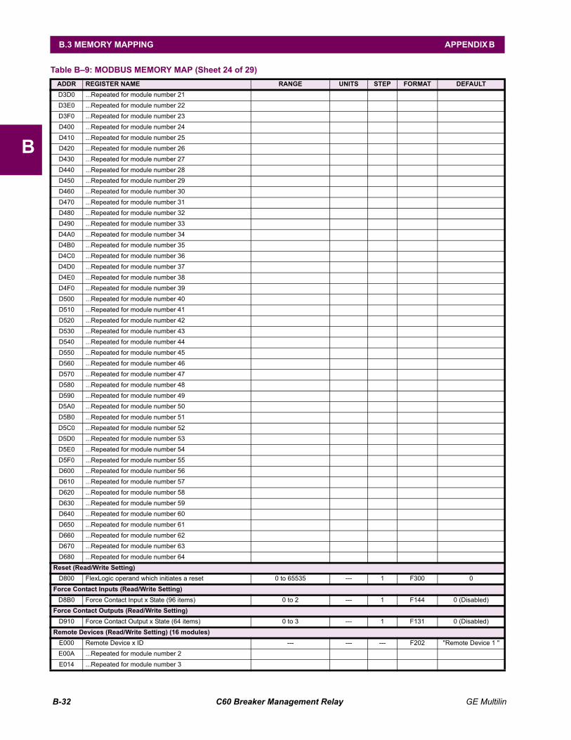
B-32 C60 Breaker Management Relay GE Multilin
B.3 MEMORY MAPPING APPENDIX B
B
D3D0 ...Repeated for module number 21 D3E0 ...Repeated for module number 22 D3F0 ...Repeated for module number 23 D400 ...Repeated for module number 24 D410 ...Repeated for module number 25 D420 ...Repeated for module number 26 D430 ...Repeated for module number 27 D440 ...Repeated for module number 28 D450 ...Repeated for module number 29 D460 ...Repeated for module number 30 D470 ...Repeated for module number 31 D480 ...Repeated for module number 32 D490 ...Repeated for module number 33 D4A0 ...Repeated for module number 34 D4B0 ...Repeated for module number 35 D4C0 ...Repeated for module number 36 D4D0 ...Repeated for module number 37 D4E0 ...Repeated for module number 38 D4F0 ...Repeated for module number 39 D500 ...Repeated for module number 40 D510 ...Repeated for module number 41 D520 ...Repeated for module number 42 D530 ...Repeated for module number 43 D540 ...Repeated for module number 44 D550 ...Repeated for module number 45 D560 ...Repeated for module number 46 D570 ...Repeated for module number 47 D580 ...Repeated for module number 48 D590 ...Repeated for module number 49 D5A0 ...Repeated for module number 50 D5B0 ...Repeated for module number 51 D5C0 ...Repeated for module number 52 D5D0 ...Repeated for module number 53 D5E0 ...Repeated for module number 54 D5F0 ...Repeated for module number 55 D600 ...Repeated for module number 56 D610 ...Repeated for module number 57 D620 ...Repeated for module number 58 D630 ...Repeated for module number 59 D640 ...Repeated for module number 60 D650 ...Repeated for module number 61 D660 ...Repeated for module number 62 D670 ...Repeated for module number 63 D680 ...Repeated for module number 64
Reset (Read/Write Setting)D800 FlexLogic operand which initiates a reset 0 to 65535 --- 1 F300 0
Force Contact Inputs (Read/Write Setting)D8B0 Force Contact Input x State (96 items) 0 to 2 --- 1 F144 0 (Disabled)
Force Contact Outputs (Read/Write Setting)D910 Force Contact Output x State (64 items) 0 to 3 --- 1 F131 0 (Disabled)
Remote Devices (Read/Write Setting) (16 modules)E000 Remote Device x ID --- --- --- F202 "Remote Device 1 " E00A ...Repeated for module number 2 E014 ...Repeated for module number 3
Table B9: MODBUS MEMORY MAP (Sheet 24 of 29)ADDR REGISTER NAME RANGE UNITS STEP FORMAT DEFAULT
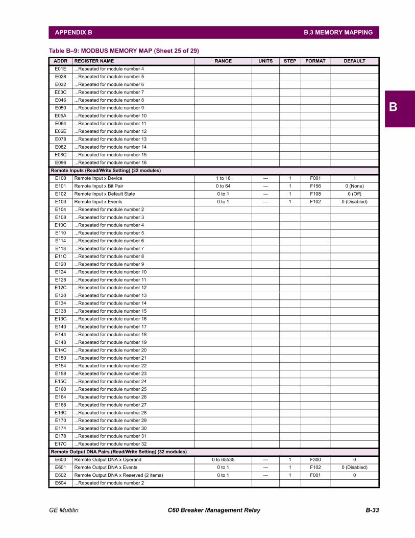
GE Multilin C60 Breaker Management Relay B-33
APPENDIX B B.3 MEMORY MAPPING
B
E01E ...Repeated for module number 4 E028 ...Repeated for module number 5 E032 ...Repeated for module number 6 E03C ...Repeated for module number 7 E046 ...Repeated for module number 8 E050 ...Repeated for module number 9 E05A ...Repeated for module number 10 E064 ...Repeated for module number 11 E06E ...Repeated for module number 12 E078 ...Repeated for module number 13 E082 ...Repeated for module number 14 E08C ...Repeated for module number 15 E096 ...Repeated for module number 16
Remote Inputs (Read/Write Setting) (32 modules)E100 Remote Input x Device 1 to 16 --- 1 F001 1 E101 Remote Input x Bit Pair 0 to 64 --- 1 F156 0 (None) E102 Remote Input x Default State 0 to 1 --- 1 F108 0 (Off) E103 Remote Input x Events 0 to 1 --- 1 F102 0 (Disabled) E104 ...Repeated for module number 2 E108 ...Repeated for module number 3 E10C ...Repeated for module number 4 E110 ...Repeated for module number 5 E114 ...Repeated for module number 6 E118 ...Repeated for module number 7 E11C ...Repeated for module number 8 E120 ...Repeated for module number 9 E124 ...Repeated for module number 10 E128 ...Repeated for module number 11 E12C ...Repeated for module number 12 E130 ...Repeated for module number 13 E134 ...Repeated for module number 14 E138 ...Repeated for module number 15 E13C ...Repeated for module number 16 E140 ...Repeated for module number 17 E144 ...Repeated for module number 18 E148 ...Repeated for module number 19 E14C ...Repeated for module number 20 E150 ...Repeated for module number 21 E154 ...Repeated for module number 22 E158 ...Repeated for module number 23 E15C ...Repeated for module number 24 E160 ...Repeated for module number 25 E164 ...Repeated for module number 26 E168 ...Repeated for module number 27 E16C ...Repeated for module number 28 E170 ...Repeated for module number 29 E174 ...Repeated for module number 30 E178 ...Repeated for module number 31 E17C ...Repeated for module number 32
Remote Output DNA Pairs (Read/Write Setting) (32 modules)E600 Remote Output DNA x Operand 0 to 65535 --- 1 F300 0 E601 Remote Output DNA x Events 0 to 1 --- 1 F102 0 (Disabled) E602 Remote Output DNA x Reserved (2 items) 0 to 1 --- 1 F001 0 E604 ...Repeated for module number 2
Table B9: MODBUS MEMORY MAP (Sheet 25 of 29)ADDR REGISTER NAME RANGE UNITS STEP FORMAT DEFAULT
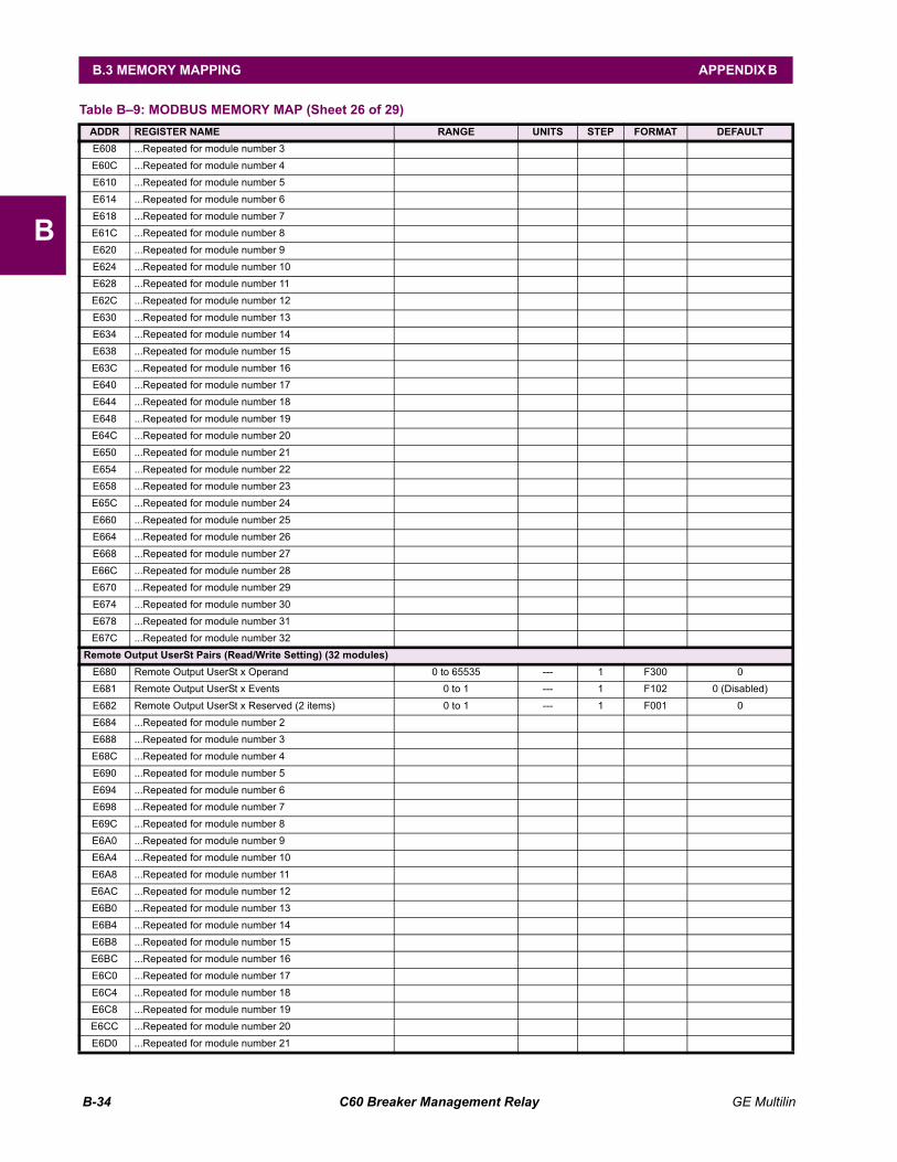
B-34 C60 Breaker Management Relay GE Multilin
B.3 MEMORY MAPPING APPENDIX B
B
E608 ...Repeated for module number 3 E60C ...Repeated for module number 4 E610 ...Repeated for module number 5 E614 ...Repeated for module number 6 E618 ...Repeated for module number 7 E61C ...Repeated for module number 8 E620 ...Repeated for module number 9 E624 ...Repeated for module number 10 E628 ...Repeated for module number 11 E62C ...Repeated for module number 12 E630 ...Repeated for module number 13 E634 ...Repeated for module number 14 E638 ...Repeated for module number 15 E63C ...Repeated for module number 16 E640 ...Repeated for module number 17 E644 ...Repeated for module number 18 E648 ...Repeated for module number 19 E64C ...Repeated for module number 20 E650 ...Repeated for module number 21 E654 ...Repeated for module number 22 E658 ...Repeated for module number 23 E65C ...Repeated for module number 24 E660 ...Repeated for module number 25 E664 ...Repeated for module number 26 E668 ...Repeated for module number 27 E66C ...Repeated for module number 28 E670 ...Repeated for module number 29 E674 ...Repeated for module number 30 E678 ...Repeated for module number 31 E67C ...Repeated for module number 32
Remote Output UserSt Pairs (Read/Write Setting) (32 modules)E680 Remote Output UserSt x Operand 0 to 65535 --- 1 F300 0 E681 Remote Output UserSt x Events 0 to 1 --- 1 F102 0 (Disabled) E682 Remote Output UserSt x Reserved (2 items) 0 to 1 --- 1 F001 0 E684 ...Repeated for module number 2 E688 ...Repeated for module number 3 E68C ...Repeated for module number 4 E690 ...Repeated for module number 5 E694 ...Repeated for module number 6 E698 ...Repeated for module number 7 E69C ...Repeated for module number 8 E6A0 ...Repeated for module number 9 E6A4 ...Repeated for module number 10 E6A8 ...Repeated for module number 11 E6AC ...Repeated for module number 12 E6B0 ...Repeated for module number 13 E6B4 ...Repeated for module number 14 E6B8 ...Repeated for module number 15 E6BC ...Repeated for module number 16 E6C0 ...Repeated for module number 17 E6C4 ...Repeated for module number 18 E6C8 ...Repeated for module number 19 E6CC ...Repeated for module number 20 E6D0 ...Repeated for module number 21
Table B9: MODBUS MEMORY MAP (Sheet 26 of 29)ADDR REGISTER NAME RANGE UNITS STEP FORMAT DEFAULT
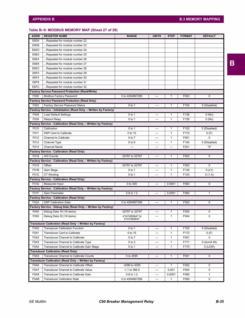
GE Multilin C60 Breaker Management Relay B-35
APPENDIX B B.3 MEMORY MAPPING
B
E6D4 ...Repeated for module number 22 E6D8 ...Repeated for module number 23 E6DC ...Repeated for module number 24 E6E0 ...Repeated for module number 25 E6E4 ...Repeated for module number 26 E6E8 ...Repeated for module number 27 E6EC ...Repeated for module number 28 E6F0 ...Repeated for module number 29 E6F4 ...Repeated for module number 30 E6F8 ...Repeated for module number 31 E6FC ...Repeated for module number 32
Factory Service Password Protection (Read/Write)F000 Modbus Factory Password 0 to 4294967295 --- 1 F003 0
Factory Service Password Protection (Read Only)F002 Factory Service Password Status 0 to 1 --- 1 F102 0 (Disabled)
Factory Service - Initialization (Read Only -- Written by Factory)F008 Load Default Settings 0 to 1 --- 1 F126 0 (No) F009 Reboot Relay 0 to 1 --- 1 F126 0 (No)
Factory Service - Calibration (Read Only -- Written by Factory)F010 Calibration 0 to 1 --- 1 F102 0 (Disabled) F011 DSP Card to Calibrate 0 to 15 --- 1 F172 0 (F) F012 Channel to Calibrate 0 to 7 --- 1 F001 0 F013 Channel Type 0 to 6 --- 1 F140 0 (Disabled) F014 Channel Name --- --- --- F201 "0"
Factory Service - Calibration (Read Only)F018 A/D Counts -32767 to 32767 --- 1 F002 0
Factory Service - Calibration (Read Only -- Written by Factory)F019 Offset -32767 to 32767 --- 1 F002 0 F01B Gain Stage 0 to 1 --- 1 F135 0 (x1) F01C CT Winding 0 to 1 --- 1 F123 0 (1 A)
Factory Service - Calibration (Read Only)F01D Measured Input 0 to 300 --- 0.0001 F060 0
Factory Service - Calibration (Read Only -- Written by Factory)F01F Gain Parameter 0.8 to 1.2 --- 0.0001 F060 1
Factory Service - Calibration (Read Only)F02A DSP Calibration Date 0 to 4294967295 --- 1 F050 0
Factory Service - Debug Data (Read Only -- Written by Factory)F040 Debug Data 16 (16 items) -32767 to 32767 --- 1 F002 0 F050 Debug Data 32 (16 items) -2147483647 to
2147483647--- 1 F004 0
Transducer Calibration (Read Only -- Written by Factory)F0A0 Transducer Calibration Function 0 to 1 --- 1 F102 0 (Disabled) F0A1 Transducer Card to Calibrate 0 to 15 --- 1 F172 0 (F) F0A2 Transducer Channel to Calibrate 0 to 7 --- 1 F001 0 F0A3 Transducer Channel to Calibrate Type 0 to 3 --- 1 F171 0 (dcmA IN) F0A4 Transducer Channel to Calibrate Gain Stage 0 to 1 --- 1 F170 0 (LOW)
Transducer Calibration (Read Only)F0A5 Transducer Channel to Calibrate Counts 0 to 4095 --- 1 F001 0
Transducer Calibration (Read Only -- Written by Factory)F0A6 Transducer Channel to Calibrate Offset -4096 to 4095 --- 1 F002 0 F0A7 Transducer Channel to Calibrate Value -1.1 to 366.5 --- 0.001 F004 0 F0A9 Transducer Channel to Calibrate Gain 0.8 to 1.2 --- 0.0001 F060 1 F0AB Transducer Calibration Date 0 to 4294967295 --- 1 F050 0
Table B9: MODBUS MEMORY MAP (Sheet 27 of 29)ADDR REGISTER NAME RANGE UNITS STEP FORMAT DEFAULT
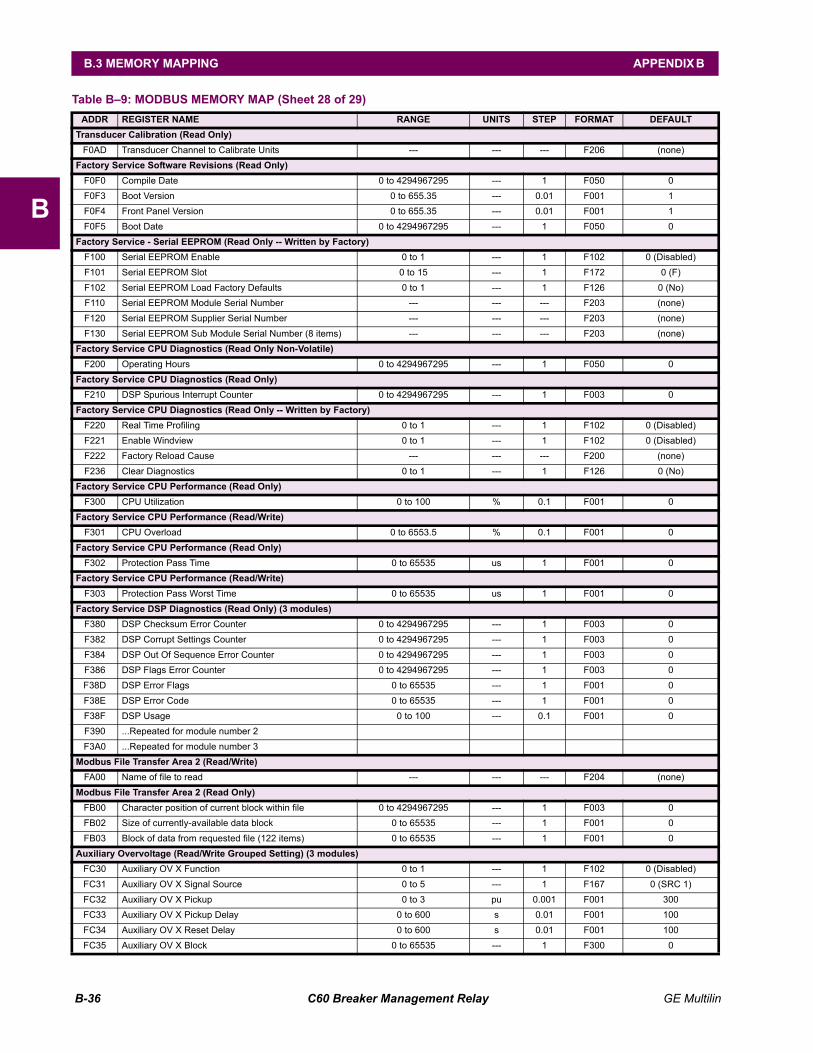
B-36 C60 Breaker Management Relay GE Multilin
B.3 MEMORY MAPPING APPENDIX B
B
Transducer Calibration (Read Only)F0AD Transducer Channel to Calibrate Units --- --- --- F206 (none)
Factory Service Software Revisions (Read Only)F0F0 Compile Date 0 to 4294967295 --- 1 F050 0 F0F3 Boot Version 0 to 655.35 --- 0.01 F001 1 F0F4 Front Panel Version 0 to 655.35 --- 0.01 F001 1 F0F5 Boot Date 0 to 4294967295 --- 1 F050 0
Factory Service - Serial EEPROM (Read Only -- Written by Factory)F100 Serial EEPROM Enable 0 to 1 --- 1 F102 0 (Disabled) F101 Serial EEPROM Slot 0 to 15 --- 1 F172 0 (F) F102 Serial EEPROM Load Factory Defaults 0 to 1 --- 1 F126 0 (No) F110 Serial EEPROM Module Serial Number --- --- --- F203 (none) F120 Serial EEPROM Supplier Serial Number --- --- --- F203 (none) F130 Serial EEPROM Sub Module Serial Number (8 items) --- --- --- F203 (none)
Factory Service CPU Diagnostics (Read Only Non-Volatile)F200 Operating Hours 0 to 4294967295 --- 1 F050 0
Factory Service CPU Diagnostics (Read Only)F210 DSP Spurious Interrupt Counter 0 to 4294967295 --- 1 F003 0
Factory Service CPU Diagnostics (Read Only -- Written by Factory)F220 Real Time Profiling 0 to 1 --- 1 F102 0 (Disabled) F221 Enable Windview 0 to 1 --- 1 F102 0 (Disabled) F222 Factory Reload Cause --- --- --- F200 (none) F236 Clear Diagnostics 0 to 1 --- 1 F126 0 (No)
Factory Service CPU Performance (Read Only)F300 CPU Utilization 0 to 100 % 0.1 F001 0
Factory Service CPU Performance (Read/Write)F301 CPU Overload 0 to 6553.5 % 0.1 F001 0
Factory Service CPU Performance (Read Only)F302 Protection Pass Time 0 to 65535 us 1 F001 0
Factory Service CPU Performance (Read/Write)F303 Protection Pass Worst Time 0 to 65535 us 1 F001 0
Factory Service DSP Diagnostics (Read Only) (3 modules)F380 DSP Checksum Error Counter 0 to 4294967295 --- 1 F003 0 F382 DSP Corrupt Settings Counter 0 to 4294967295 --- 1 F003 0 F384 DSP Out Of Sequence Error Counter 0 to 4294967295 --- 1 F003 0 F386 DSP Flags Error Counter 0 to 4294967295 --- 1 F003 0 F38D DSP Error Flags 0 to 65535 --- 1 F001 0 F38E DSP Error Code 0 to 65535 --- 1 F001 0 F38F DSP Usage 0 to 100 --- 0.1 F001 0 F390 ...Repeated for module number 2 F3A0 ...Repeated for module number 3
Modbus File Transfer Area 2 (Read/Write)FA00 Name of file to read --- --- --- F204 (none)
Modbus File Transfer Area 2 (Read Only)FB00 Character position of current block within file 0 to 4294967295 --- 1 F003 0 FB02 Size of currently-available data block 0 to 65535 --- 1 F001 0 FB03 Block of data from requested file (122 items) 0 to 65535 --- 1 F001 0
Auxiliary Overvoltage (Read/Write Grouped Setting) (3 modules)FC30 Auxiliary OV X Function 0 to 1 --- 1 F102 0 (Disabled) FC31 Auxiliary OV X Signal Source 0 to 5 --- 1 F167 0 (SRC 1) FC32 Auxiliary OV X Pickup 0 to 3 pu 0.001 F001 300 FC33 Auxiliary OV X Pickup Delay 0 to 600 s 0.01 F001 100 FC34 Auxiliary OV X Reset Delay 0 to 600 s 0.01 F001 100 FC35 Auxiliary OV X Block 0 to 65535 --- 1 F300 0
Table B9: MODBUS MEMORY MAP (Sheet 28 of 29)ADDR REGISTER NAME RANGE UNITS STEP FORMAT DEFAULT
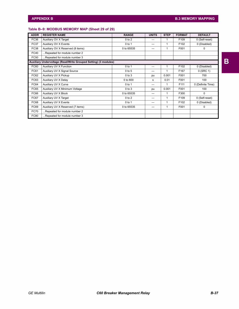
GE Multilin C60 Breaker Management Relay B-37
APPENDIX B B.3 MEMORY MAPPING
B
FC36 Auxiliary OV X Target 0 to 2 --- 1 F109 0 (Self-reset) FC37 Auxiliary OV X Events 0 to 1 --- 1 F102 0 (Disabled) FC38 Auxiliary OV X Reserved (8 items) 0 to 65535 --- 1 F001 0 FC40 ...Repeated for module number 2 FC50 ...Repeated for module number 3
Auxiliary Undervoltage (Read/Write Grouped Setting) (3 modules)FC60 Auxiliary UV X Function 0 to 1 --- 1 F102 0 (Disabled) FC61 Auxiliary UV X Signal Source 0 to 5 --- 1 F167 0 (SRC 1) FC62 Auxiliary UV X Pickup 0 to 3 pu 0.001 F001 700 FC63 Auxiliary UV X Delay 0 to 600 s 0.01 F001 100 FC64 Auxiliary UV X Curve 0 to 1 --- 1 F111 0 (Definite Time) FC65 Auxiliary UV X Minimum Voltage 0 to 3 pu 0.001 F001 100 FC66 Auxiliary UV X Block 0 to 65535 --- 1 F300 0 FC67 Auxiliary UV X Target 0 to 2 --- 1 F109 0 (Self-reset) FC68 Auxiliary UV X Events 0 to 1 --- 1 F102 0 (Disabled) FC69 Auxiliary UV X Reserved (7 items) 0 to 65535 --- 1 F001 0 FC70 ...Repeated for module number 2 FC80 ...Repeated for module number 3
Table B9: MODBUS MEMORY MAP (Sheet 29 of 29)ADDR REGISTER NAME RANGE UNITS STEP FORMAT DEFAULT
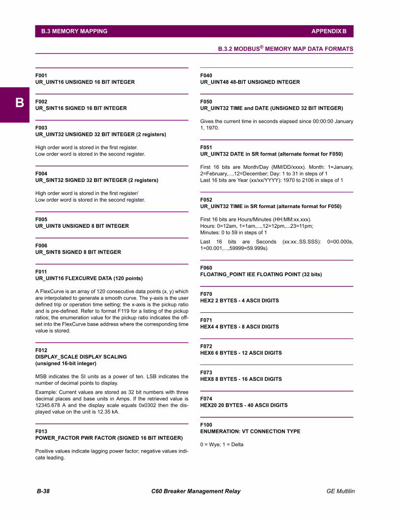
B-38 C60 Breaker Management Relay GE Multilin
B.3 MEMORY MAPPING APPENDIX B
B
B.3.2 MODBUS® MEMORY MAP DATA FORMATS
F001UR_UINT16 UNSIGNED 16 BIT INTEGER
F002UR_SINT16 SIGNED 16 BIT INTEGER
F003UR_UINT32 UNSIGNED 32 BIT INTEGER (2 registers)
High order word is stored in the first register. Low order word is stored in the second register.
F004UR_SINT32 SIGNED 32 BIT INTEGER (2 registers)
High order word is stored in the first register/Low order word is stored in the second register.
F005UR_UINT8 UNSIGNED 8 BIT INTEGER
F006UR_SINT8 SIGNED 8 BIT INTEGER
F011UR_UINT16 FLEXCURVE DATA (120 points)
A FlexCurve is an array of 120 consecutive data points (x, y) whichare interpolated to generate a smooth curve. The y-axis is the userdefined trip or operation time setting; the x-axis is the pickup ratioand is pre-defined. Refer to format F119 for a listing of the pickupratios; the enumeration value for the pickup ratio indicates the off-set into the FlexCurve base address where the corresponding timevalue is stored.
F012DISPLAY_SCALE DISPLAY SCALING(unsigned 16-bit integer)
MSB indicates the SI units as a power of ten. LSB indicates thenumber of decimal points to display.
Example: Current values are stored as 32 bit numbers with threedecimal places and base units in Amps. If the retrieved value is12345.678 A and the display scale equals 0x0302 then the dis-played value on the unit is 12.35 kA.
F013POWER_FACTOR PWR FACTOR (SIGNED 16 BIT INTEGER)
Positive values indicate lagging power factor; negative values indi-cate leading.
F040UR_UINT48 48-BIT UNSIGNED INTEGER
F050UR_UINT32 TIME and DATE (UNSIGNED 32 BIT INTEGER)
Gives the current time in seconds elapsed since 00:00:00 January1, 1970.
F051UR_UINT32 DATE in SR format (alternate format for F050)
First 16 bits are Month/Day (MM/DD/xxxx). Month: 1=January,2=February,...,12=December; Day: 1 to 31 in steps of 1Last 16 bits are Year (xx/xx/YYYY): 1970 to 2106 in steps of 1
F052UR_UINT32 TIME in SR format (alternate format for F050)
First 16 bits are Hours/Minutes (HH:MM:xx.xxx).Hours: 0=12am, 1=1am,...,12=12pm,...23=11pm;Minutes: 0 to 59 in steps of 1
Last 16 bits are Seconds (xx:xx:.SS.SSS): 0=00.000s,1=00.001,...,59999=59.999s)
F060FLOATING_POINT IEE FLOATING POINT (32 bits)
F070HEX2 2 BYTES - 4 ASCII DIGITS
F071HEX4 4 BYTES - 8 ASCII DIGITS
F072HEX6 6 BYTES - 12 ASCII DIGITS
F073HEX8 8 BYTES - 16 ASCII DIGITS
F074HEX20 20 BYTES - 40 ASCII DIGITS
F100ENUMERATION: VT CONNECTION TYPE
0 = Wye; 1 = Delta
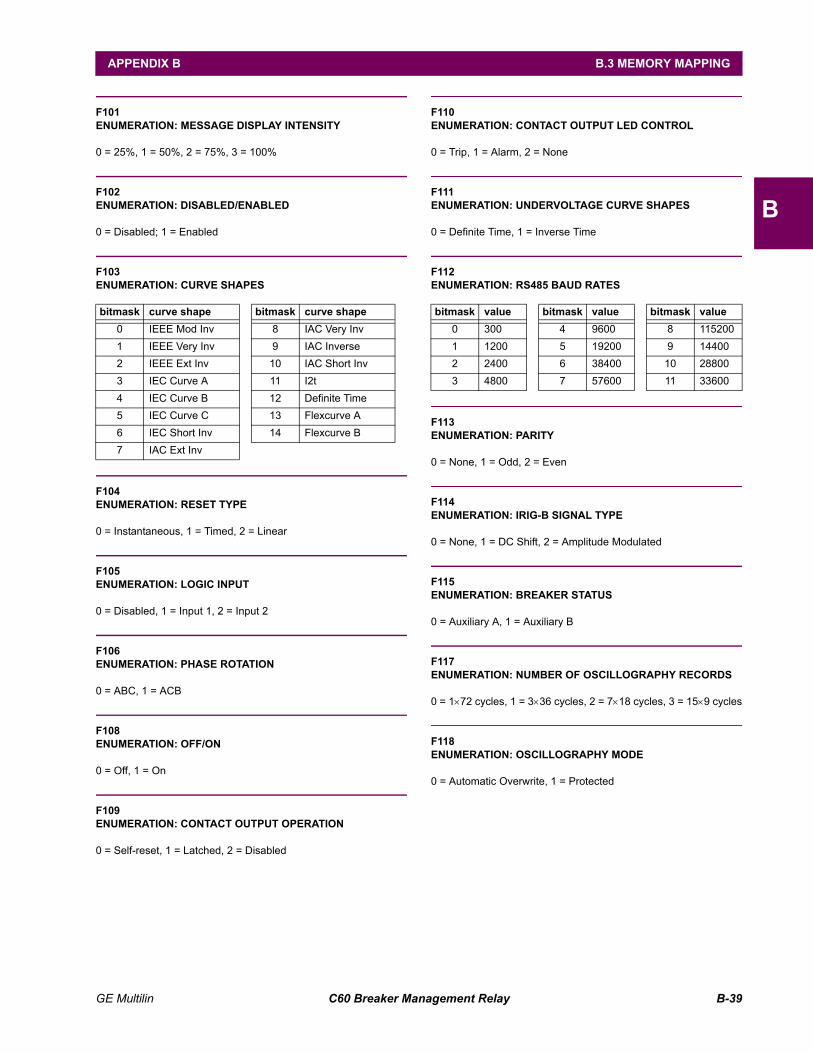
GE Multilin C60 Breaker Management Relay B-39
APPENDIX B B.3 MEMORY MAPPING
B
F101ENUMERATION: MESSAGE DISPLAY INTENSITY
0 = 25%, 1 = 50%, 2 = 75%, 3 = 100%
F102ENUMERATION: DISABLED/ENABLED
0 = Disabled; 1 = Enabled
F103ENUMERATION: CURVE SHAPES
F104ENUMERATION: RESET TYPE
0 = Instantaneous, 1 = Timed, 2 = Linear
F105ENUMERATION: LOGIC INPUT
0 = Disabled, 1 = Input 1, 2 = Input 2
F106ENUMERATION: PHASE ROTATION
0 = ABC, 1 = ACB
F108ENUMERATION: OFF/ON
0 = Off, 1 = On
F109ENUMERATION: CONTACT OUTPUT OPERATION
0 = Self-reset, 1 = Latched, 2 = Disabled
F110ENUMERATION: CONTACT OUTPUT LED CONTROL
0 = Trip, 1 = Alarm, 2 = None
F111ENUMERATION: UNDERVOLTAGE CURVE SHAPES
0 = Definite Time, 1 = Inverse Time
F112ENUMERATION: RS485 BAUD RATES
F113ENUMERATION: PARITY
0 = None, 1 = Odd, 2 = Even
F114ENUMERATION: IRIG-B SIGNAL TYPE
0 = None, 1 = DC Shift, 2 = Amplitude Modulated
F115ENUMERATION: BREAKER STATUS
0 = Auxiliary A, 1 = Auxiliary B
F117ENUMERATION: NUMBER OF OSCILLOGRAPHY RECORDS
0 = 1×72 cycles, 1 = 3×36 cycles, 2 = 7×18 cycles, 3 = 15×9 cycles
F118ENUMERATION: OSCILLOGRAPHY MODE
0 = Automatic Overwrite, 1 = Protected
bitmask curve shape bitmask curve shape0 IEEE Mod Inv 8 IAC Very Inv 1 IEEE Very Inv 9 IAC Inverse 2 IEEE Ext Inv 10 IAC Short Inv 3 IEC Curve A 11 I2t 4 IEC Curve B 12 Definite Time 5 IEC Curve C 13 Flexcurve A 6 IEC Short Inv 14 Flexcurve B 7 IAC Ext Inv
bitmask value bitmask value bitmask value0 300 4 9600 8 1152001 1200 5 19200 9 144002 2400 6 38400 10 288003 4800 7 57600 11 33600
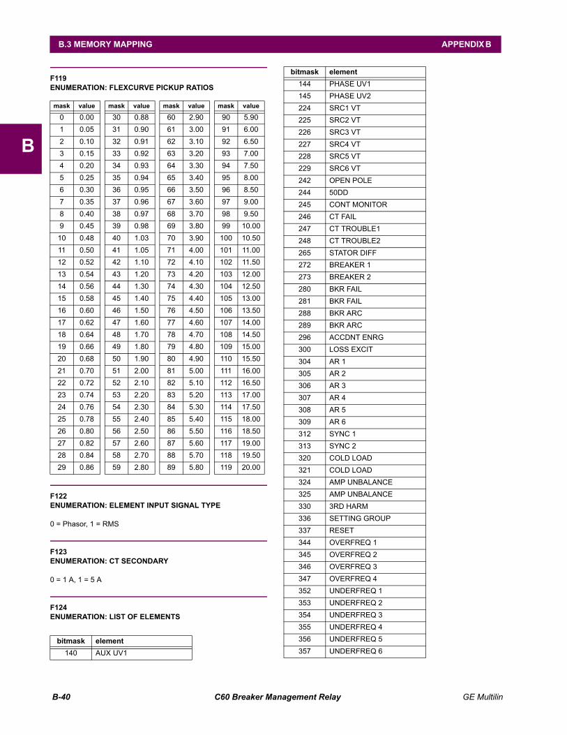
B-40 C60 Breaker Management Relay GE Multilin
B.3 MEMORY MAPPING APPENDIX B
B
F119ENUMERATION: FLEXCURVE PICKUP RATIOS
F122ENUMERATION: ELEMENT INPUT SIGNAL TYPE
0 = Phasor, 1 = RMS
F123ENUMERATION: CT SECONDARY
0 = 1 A, 1 = 5 A
F124ENUMERATION: LIST OF ELEMENTS
mask value mask value mask value mask value
0 0.00 30 0.88 60 2.90 90 5.901 0.05 31 0.90 61 3.00 91 6.002 0.10 32 0.91 62 3.10 92 6.503 0.15 33 0.92 63 3.20 93 7.004 0.20 34 0.93 64 3.30 94 7.505 0.25 35 0.94 65 3.40 95 8.006 0.30 36 0.95 66 3.50 96 8.507 0.35 37 0.96 67 3.60 97 9.008 0.40 38 0.97 68 3.70 98 9.509 0.45 39 0.98 69 3.80 99 10.00
10 0.48 40 1.03 70 3.90 100 10.5011 0.50 41 1.05 71 4.00 101 11.0012 0.52 42 1.10 72 4.10 102 11.5013 0.54 43 1.20 73 4.20 103 12.0014 0.56 44 1.30 74 4.30 104 12.5015 0.58 45 1.40 75 4.40 105 13.0016 0.60 46 1.50 76 4.50 106 13.5017 0.62 47 1.60 77 4.60 107 14.0018 0.64 48 1.70 78 4.70 108 14.5019 0.66 49 1.80 79 4.80 109 15.0020 0.68 50 1.90 80 4.90 110 15.5021 0.70 51 2.00 81 5.00 111 16.0022 0.72 52 2.10 82 5.10 112 16.5023 0.74 53 2.20 83 5.20 113 17.0024 0.76 54 2.30 84 5.30 114 17.5025 0.78 55 2.40 85 5.40 115 18.0026 0.80 56 2.50 86 5.50 116 18.5027 0.82 57 2.60 87 5.60 117 19.0028 0.84 58 2.70 88 5.70 118 19.5029 0.86 59 2.80 89 5.80 119 20.00
bitmask element140 AUX UV1
144 PHASE UV1145 PHASE UV2224 SRC1 VT225 SRC2 VT226 SRC3 VT227 SRC4 VT228 SRC5 VT229 SRC6 VT242 OPEN POLE244 50DD245 CONT MONITOR246 CT FAIL247 CT TROUBLE1248 CT TROUBLE2265 STATOR DIFF272 BREAKER 1273 BREAKER 2280 BKR FAIL281 BKR FAIL288 BKR ARC289 BKR ARC296 ACCDNT ENRG300 LOSS EXCIT304 AR 1305 AR 2306 AR 3307 AR 4308 AR 5309 AR 6312 SYNC 1313 SYNC 2320 COLD LOAD321 COLD LOAD324 AMP UNBALANCE325 AMP UNBALANCE330 3RD HARM336 SETTING GROUP337 RESET344 OVERFREQ 1345 OVERFREQ 2346 OVERFREQ 3347 OVERFREQ 4352 UNDERFREQ 1353 UNDERFREQ 2354 UNDERFREQ 3355 UNDERFREQ 4356 UNDERFREQ 5357 UNDERFREQ 6
bitmask element
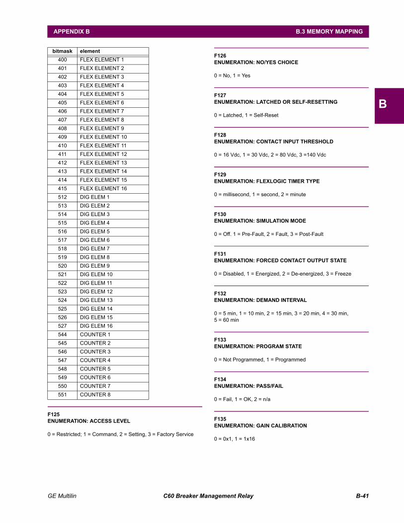
GE Multilin C60 Breaker Management Relay B-41
APPENDIX B B.3 MEMORY MAPPING
B
F125ENUMERATION: ACCESS LEVEL
0 = Restricted; 1 = Command, 2 = Setting, 3 = Factory Service
F126ENUMERATION: NO/YES CHOICE
0 = No, 1 = Yes
F127ENUMERATION: LATCHED OR SELF-RESETTING
0 = Latched, 1 = Self-Reset
F128ENUMERATION: CONTACT INPUT THRESHOLD
0 = 16 Vdc, 1 = 30 Vdc, 2 = 80 Vdc, 3 =140 Vdc
F129ENUMERATION: FLEXLOGIC TIMER TYPE
0 = millisecond, 1 = second, 2 = minute
F130ENUMERATION: SIMULATION MODE
0 = Off. 1 = Pre-Fault, 2 = Fault, 3 = Post-Fault
F131ENUMERATION: FORCED CONTACT OUTPUT STATE
0 = Disabled, 1 = Energized, 2 = De-energized, 3 = Freeze
F132ENUMERATION: DEMAND INTERVAL
0 = 5 min, 1 = 10 min, 2 = 15 min, 3 = 20 min, 4 = 30 min,5 = 60 min
F133ENUMERATION: PROGRAM STATE
0 = Not Programmed, 1 = Programmed
F134ENUMERATION: PASS/FAIL
0 = Fail, 1 = OK, 2 = n/a
F135ENUMERATION: GAIN CALIBRATION
0 = 0x1, 1 = 1x16
400 FLEX ELEMENT 1401 FLEX ELEMENT 2402 FLEX ELEMENT 3403 FLEX ELEMENT 4404 FLEX ELEMENT 5405 FLEX ELEMENT 6406 FLEX ELEMENT 7407 FLEX ELEMENT 8408 FLEX ELEMENT 9409 FLEX ELEMENT 10410 FLEX ELEMENT 11411 FLEX ELEMENT 12412 FLEX ELEMENT 13413 FLEX ELEMENT 14414 FLEX ELEMENT 15415 FLEX ELEMENT 16512 DIG ELEM 1513 DIG ELEM 2514 DIG ELEM 3515 DIG ELEM 4516 DIG ELEM 5517 DIG ELEM 6518 DIG ELEM 7519 DIG ELEM 8520 DIG ELEM 9521 DIG ELEM 10522 DIG ELEM 11523 DIG ELEM 12524 DIG ELEM 13525 DIG ELEM 14526 DIG ELEM 15527 DIG ELEM 16544 COUNTER 1545 COUNTER 2546 COUNTER 3547 COUNTER 4548 COUNTER 5549 COUNTER 6550 COUNTER 7551 COUNTER 8
bitmask element
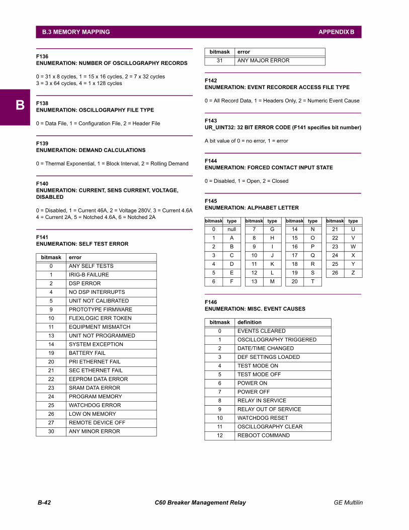
B-42 C60 Breaker Management Relay GE Multilin
B.3 MEMORY MAPPING APPENDIX B
B
F136ENUMERATION: NUMBER OF OSCILLOGRAPHY RECORDS
0 = 31 x 8 cycles, 1 = 15 x 16 cycles, 2 = 7 x 32 cycles3 = 3 x 64 cycles, 4 = 1 x 128 cycles
F138ENUMERATION: OSCILLOGRAPHY FILE TYPE
0 = Data File, 1 = Configuration File, 2 = Header File
F139ENUMERATION: DEMAND CALCULATIONS
0 = Thermal Exponential, 1 = Block Interval, 2 = Rolling Demand
F140ENUMERATION: CURRENT, SENS CURRENT, VOLTAGE,DISABLED
0 = Disabled, 1 = Current 46A, 2 = Voltage 280V, 3 = Current 4.6A4 = Current 2A, 5 = Notched 4.6A, 6 = Notched 2A
F141ENUMERATION: SELF TEST ERROR
F142ENUMERATION: EVENT RECORDER ACCESS FILE TYPE
0 = All Record Data, 1 = Headers Only, 2 = Numeric Event Cause
F143UR_UINT32: 32 BIT ERROR CODE (F141 specifies bit number)
A bit value of 0 = no error, 1 = error
F144ENUMERATION: FORCED CONTACT INPUT STATE
0 = Disabled, 1 = Open, 2 = Closed
F145ENUMERATION: ALPHABET LETTER
F146ENUMERATION: MISC. EVENT CAUSES
bitmask error0 ANY SELF TESTS 1 IRIG-B FAILURE 2 DSP ERROR 4 NO DSP INTERRUPTS 5 UNIT NOT CALIBRATED 9 PROTOTYPE FIRMWARE
10 FLEXLOGIC ERR TOKEN 11 EQUIPMENT MISMATCH 13 UNIT NOT PROGRAMMED 14 SYSTEM EXCEPTION 19 BATTERY FAIL 20 PRI ETHERNET FAIL 21 SEC ETHERNET FAIL 22 EEPROM DATA ERROR 23 SRAM DATA ERROR 24 PROGRAM MEMORY 25 WATCHDOG ERROR 26 LOW ON MEMORY 27 REMOTE DEVICE OFF 30 ANY MINOR ERROR
31 ANY MAJOR ERROR
bitmask type bitmask type bitmask type bitmask type
0 null 7 G 14 N 21 U1 A 8 H 15 O 22 V2 B 9 I 16 P 23 W3 C 10 J 17 Q 24 X4 D 11 K 18 R 25 Y5 E 12 L 19 S 26 Z6 F 13 M 20 T
bitmask definition0 EVENTS CLEARED1 OSCILLOGRAPHY TRIGGERED2 DATE/TIME CHANGED3 DEF SETTINGS LOADED4 TEST MODE ON5 TEST MODE OFF6 POWER ON7 POWER OFF8 RELAY IN SERVICE9 RELAY OUT OF SERVICE
10 WATCHDOG RESET11 OSCILLOGRAPHY CLEAR12 REBOOT COMMAND
bitmask error
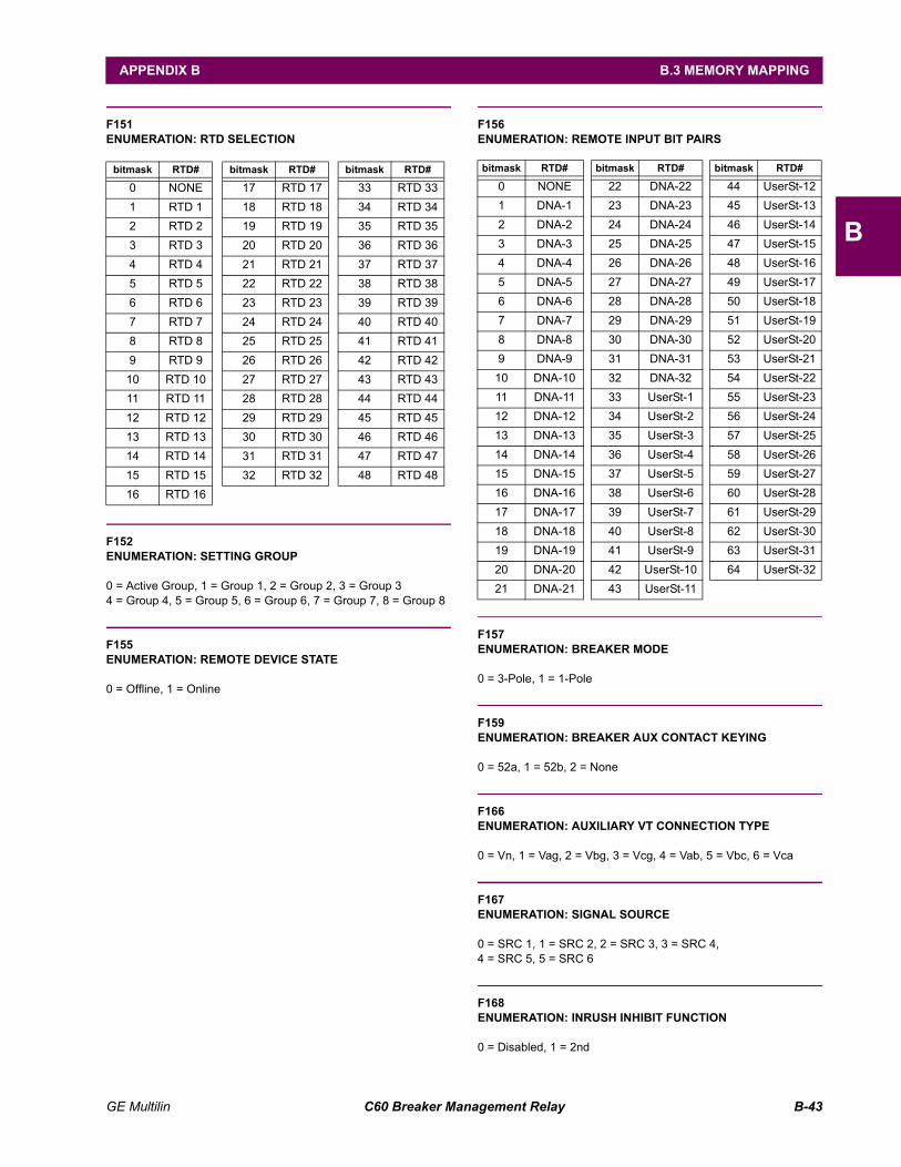
GE Multilin C60 Breaker Management Relay B-43
APPENDIX B B.3 MEMORY MAPPING
B
F151ENUMERATION: RTD SELECTION
F152ENUMERATION: SETTING GROUP
0 = Active Group, 1 = Group 1, 2 = Group 2, 3 = Group 34 = Group 4, 5 = Group 5, 6 = Group 6, 7 = Group 7, 8 = Group 8
F155ENUMERATION: REMOTE DEVICE STATE
0 = Offline, 1 = Online
F156ENUMERATION: REMOTE INPUT BIT PAIRS
F157ENUMERATION: BREAKER MODE
0 = 3-Pole, 1 = 1-Pole
F159ENUMERATION: BREAKER AUX CONTACT KEYING
0 = 52a, 1 = 52b, 2 = None
F166ENUMERATION: AUXILIARY VT CONNECTION TYPE
0 = Vn, 1 = Vag, 2 = Vbg, 3 = Vcg, 4 = Vab, 5 = Vbc, 6 = Vca
F167ENUMERATION: SIGNAL SOURCE
0 = SRC 1, 1 = SRC 2, 2 = SRC 3, 3 = SRC 4,4 = SRC 5, 5 = SRC 6
F168ENUMERATION: INRUSH INHIBIT FUNCTION
0 = Disabled, 1 = 2nd
bitmask RTD# bitmask RTD# bitmask RTD#
0 NONE 17 RTD 17 33 RTD 331 RTD 1 18 RTD 18 34 RTD 342 RTD 2 19 RTD 19 35 RTD 353 RTD 3 20 RTD 20 36 RTD 364 RTD 4 21 RTD 21 37 RTD 375 RTD 5 22 RTD 22 38 RTD 386 RTD 6 23 RTD 23 39 RTD 397 RTD 7 24 RTD 24 40 RTD 408 RTD 8 25 RTD 25 41 RTD 419 RTD 9 26 RTD 26 42 RTD 42
10 RTD 10 27 RTD 27 43 RTD 4311 RTD 11 28 RTD 28 44 RTD 4412 RTD 12 29 RTD 29 45 RTD 4513 RTD 13 30 RTD 30 46 RTD 4614 RTD 14 31 RTD 31 47 RTD 4715 RTD 15 32 RTD 32 48 RTD 4816 RTD 16
bitmask RTD# bitmask RTD# bitmask RTD#
0 NONE 22 DNA-22 44 UserSt-121 DNA-1 23 DNA-23 45 UserSt-132 DNA-2 24 DNA-24 46 UserSt-143 DNA-3 25 DNA-25 47 UserSt-154 DNA-4 26 DNA-26 48 UserSt-165 DNA-5 27 DNA-27 49 UserSt-176 DNA-6 28 DNA-28 50 UserSt-187 DNA-7 29 DNA-29 51 UserSt-198 DNA-8 30 DNA-30 52 UserSt-209 DNA-9 31 DNA-31 53 UserSt-21
10 DNA-10 32 DNA-32 54 UserSt-2211 DNA-11 33 UserSt-1 55 UserSt-2312 DNA-12 34 UserSt-2 56 UserSt-2413 DNA-13 35 UserSt-3 57 UserSt-2514 DNA-14 36 UserSt-4 58 UserSt-2615 DNA-15 37 UserSt-5 59 UserSt-2716 DNA-16 38 UserSt-6 60 UserSt-2817 DNA-17 39 UserSt-7 61 UserSt-2918 DNA-18 40 UserSt-8 62 UserSt-3019 DNA-19 41 UserSt-9 63 UserSt-3120 DNA-20 42 UserSt-10 64 UserSt-3221 DNA-21 43 UserSt-11
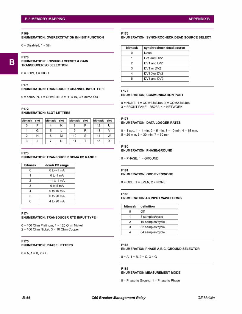
B-44 C60 Breaker Management Relay GE Multilin
B.3 MEMORY MAPPING APPENDIX B
B
F169ENUMERATION: OVEREXCITATION INHIBIT FUNCTION
0 = Disabled, 1 = 5th
F170ENUMERATION: LOW/HIGH OFFSET & GAINTRANSDUCER I/O SELECTION
0 = LOW, 1 = HIGH
F171ENUMERATION: TRANSDUCER CHANNEL INPUT TYPE
0 = dcmA IN, 1 = OHMS IN, 2 = RTD IN, 3 = dcmA OUT
F172ENUMERATION: SLOT LETTERS
F173ENUMERATION: TRANSDUCER DCMA I/O RANGE
F174ENUMERATION: TRANSDUCER RTD INPUT TYPE
0 = 100 Ohm Platinum, 1 = 120 Ohm Nickel, 2 = 100 Ohm Nickel, 3 = 10 Ohm Copper
F175ENUMERATION: PHASE LETTERS
0 = A, 1 = B, 2 = C
F176ENUMERATION: SYNCHROCHECK DEAD SOURCE SELECT
F177ENUMERATION: COMMUNICATION PORT
0 = NONE, 1 = COM1-RS485, 2 = COM2-RS485,3 = FRONT PANEL-RS232, 4 = NETWORK
F178ENUMERATION: DATA LOGGER RATES
0 = 1 sec, 1 = 1 min, 2 = 5 min, 3 = 10 min, 4 = 15 min,5 = 20 min, 6 = 30 min, 7 = 60 min
F180ENUMERATION: PHASE/GROUND
0 = PHASE, 1 = GROUND
F181ENUMERATION: ODD/EVEN/NONE
0 = ODD, 1 = EVEN, 2 = NONE
F183ENUMERATION AC INPUT WAVEFORMS
F185ENUMERATION PHASE A,B,C, GROUND SELECTOR
0 = A, 1 = B, 2 = C, 3 = G
F186ENUMERATION MEASUREMENT MODE
0 = Phase to Ground, 1 = Phase to Phase
bitmask slot bitmask slot bitmask slot bitmask slot
0 F 4 K 8 P 12 U1 G 5 L 9 R 13 V2 H 6 M 10 S 14 W3 J 7 N 11 T 15 X
bitmask dcmA I/O range0 0 to 1 mA1 0 to 1 mA2 1 to 1 mA3 0 to 5 mA4 0 to 10 mA5 0 to 20 mA6 4 to 20 mA
bitmask synchrocheck dead source0 None1 LV1 and DV2 2 DV1 and LV2 3 DV1 or DV2 4 DV1 Xor DV2 5 DV1 and DV2
bitmask definition0 Off1 8 samples/cycle2 16 samples/cycle3 32 samples/cycle4 64 samples/cycle
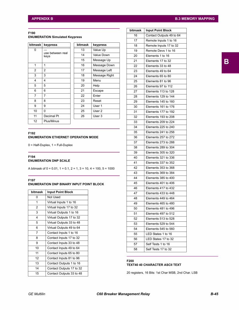
GE Multilin C60 Breaker Management Relay B-45
APPENDIX B B.3 MEMORY MAPPING
B
F190ENUMERATION Simulated Keypress
F192ENUMERATION ETHERNET OPERATION MODE
0 = Half-Duplex, 1 = Full-Duplex
F194ENUMERATION DNP SCALE
A bitmask of 0 = 0.01, 1 = 0.1, 2 = 1, 3 = 10, 4 = 100, 5 = 1000
F197ENUMERATION DNP BINARY INPUT POINT BLOCK
F200TEXT40 40 CHARACTER ASCII TEXT
20 registers, 16 Bits: 1st Char MSB, 2nd Char. LSB
bitmask keypress bitmask keypress0 ---
use between real keys
13 Value Up14 Value Down15 Message Up
1 1 16 Message Down2 2 17 Message Left3 3 18 Message Right4 4 19 Menu5 5 20 Help6 6 21 Escape7 7 22 Enter8 8 23 Reset9 9 24 User 1
10 0 25 User 211 Decimal Pt 26 User 312 Plus/Minus
bitmask Input Point Block0 Not Used1 Virtual Inputs 1 to 162 Virtual Inputs 17 to 323 Virtual Outputs 1 to 164 Virtual Outputs 17 to 325 Virtual Outputs 33 to 486 Virtual Outputs 49 to 647 Contact Inputs 1 to 168 Contact Inputs 17 to 329 Contact Inputs 33 to 48
10 Contact Inputs 49 to 6411 Contact Inputs 65 to 8012 Contact Inputs 81 to 9613 Contact Outputs 1 to 1614 Contact Outputs 17 to 3215 Contact Outputs 33 to 48
16 Contact Outputs 49 to 6417 Remote Inputs 1 to 1618 Remote Inputs 17 to 3219 Remote Devs 1 to 1620 Elements 1 to 1621 Elements 17 to 3222 Elements 33 to 4823 Elements 49 to 6424 Elements 65 to 8025 Elements 81 to 9626 Elements 97 to 11227 Elements 113 to 12828 Elements 129 to 14429 Elements 145 to 16030 Elements 161 to 17631 Elements 177 to 19232 Elements 193 to 20833 Elements 209 to 22434 Elements 225 to 24035 Elements 241 to 25636 Elements 257 to 27237 Elements 273 to 28838 Elements 289 to 30439 Elements 305 to 32040 Elements 321 to 33641 Elements 337 to 35242 Elements 353 to 36843 Elements 369 to 38444 Elements 385 to 40045 Elements 401 to 40646 Elements 417 to 43247 Elements 433 to 44848 Elements 449 to 46449 Elements 465 to 48050 Elements 481 to 49651 Elements 497 to 51252 Elements 513 to 52853 Elements 529 to 54454 Elements 545 to 56055 LED States 1 to 1656 LED States 17 to 3257 Self Tests 1 to 1658 Self Tests 17 to 32
bitmask Input Point Block
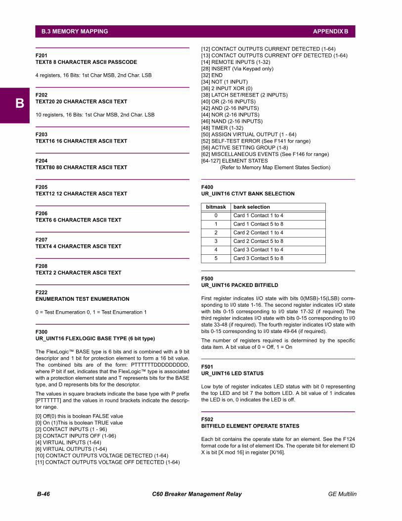
B-46 C60 Breaker Management Relay GE Multilin
B.3 MEMORY MAPPING APPENDIX B
B
F201TEXT8 8 CHARACTER ASCII PASSCODE
4 registers, 16 Bits: 1st Char MSB, 2nd Char. LSB
F202TEXT20 20 CHARACTER ASCII TEXT
10 registers, 16 Bits: 1st Char MSB, 2nd Char. LSB
F203TEXT16 16 CHARACTER ASCII TEXT
F204TEXT80 80 CHARACTER ASCII TEXT
F205TEXT12 12 CHARACTER ASCII TEXT
F206TEXT6 6 CHARACTER ASCII TEXT
F207TEXT4 4 CHARACTER ASCII TEXT
F208TEXT2 2 CHARACTER ASCII TEXT
F222ENUMERATION TEST ENUMERATION
0 = Test Enumeration 0, 1 = Test Enumeration 1
F300UR_UINT16 FLEXLOGIC BASE TYPE (6 bit type)
The FlexLogic BASE type is 6 bits and is combined with a 9 bitdescriptor and 1 bit for protection element to form a 16 bit value.The combined bits are of the form: PTTTTTTDDDDDDDDD,where P bit if set, indicates that the FlexLogic type is associatedwith a protection element state and T represents bits for the BASEtype, and D represents bits for the descriptor.
The values in square brackets indicate the base type with P prefix[PTTTTTT] and the values in round brackets indicate the descrip-tor range.
[0] Off(0) this is boolean FALSE value [0] On (1)This is boolean TRUE value [2] CONTACT INPUTS (1 - 96) [3] CONTACT INPUTS OFF (1-96) [4] VIRTUAL INPUTS (1-64) [6] VIRTUAL OUTPUTS (1-64) [10] CONTACT OUTPUTS VOLTAGE DETECTED (1-64) [11] CONTACT OUTPUTS VOLTAGE OFF DETECTED (1-64)
[12] CONTACT OUTPUTS CURRENT DETECTED (1-64) [13] CONTACT OUTPUTS CURRENT OFF DETECTED (1-64) [14] REMOTE INPUTS (1-32) [28] INSERT (Via Keypad only) [32] END [34] NOT (1 INPUT) [36] 2 INPUT XOR (0) [38] LATCH SET/RESET (2 INPUTS) [40] OR (2-16 INPUTS) [42] AND (2-16 INPUTS) [44] NOR (2-16 INPUTS) [46] NAND (2-16 INPUTS) [48] TIMER (1-32) [50] ASSIGN VIRTUAL OUTPUT (1 - 64) [52] SELF-TEST ERROR (See F141 for range) [56] ACTIVE SETTING GROUP (1-8) [62] MISCELLANEOUS EVENTS (See F146 for range) [64-127] ELEMENT STATES
(Refer to Memory Map Element States Section)
F400UR_UINT16 CT/VT BANK SELECTION
F500UR_UINT16 PACKED BITFIELD
First register indicates I/O state with bits 0(MSB)-15(LSB) corre-sponding to I/0 state 1-16. The second register indicates I/O statewith bits 0-15 corresponding to I/0 state 17-32 (if required) Thethird register indicates I/O state with bits 0-15 corresponding to I/0state 33-48 (if required). The fourth register indicates I/O state withbits 0-15 corresponding to I/0 state 49-64 (if required).
The number of registers required is determined by the specificdata item. A bit value of 0 = Off, 1 = On
F501UR_UINT16 LED STATUS
Low byte of register indicates LED status with bit 0 representingthe top LED and bit 7 the bottom LED. A bit value of 1 indicatesthe LED is on, 0 indicates the LED is off.
F502BITFIELD ELEMENT OPERATE STATES
Each bit contains the operate state for an element. See the F124format code for a list of element IDs. The operate bit for element IDX is bit [X mod 16] in register [X/16].
bitmask bank selection0 Card 1 Contact 1 to 41 Card 1 Contact 5 to 82 Card 2 Contact 1 to 43 Card 2 Contact 5 to 84 Card 3 Contact 1 to 45 Card 3 Contact 5 to 8
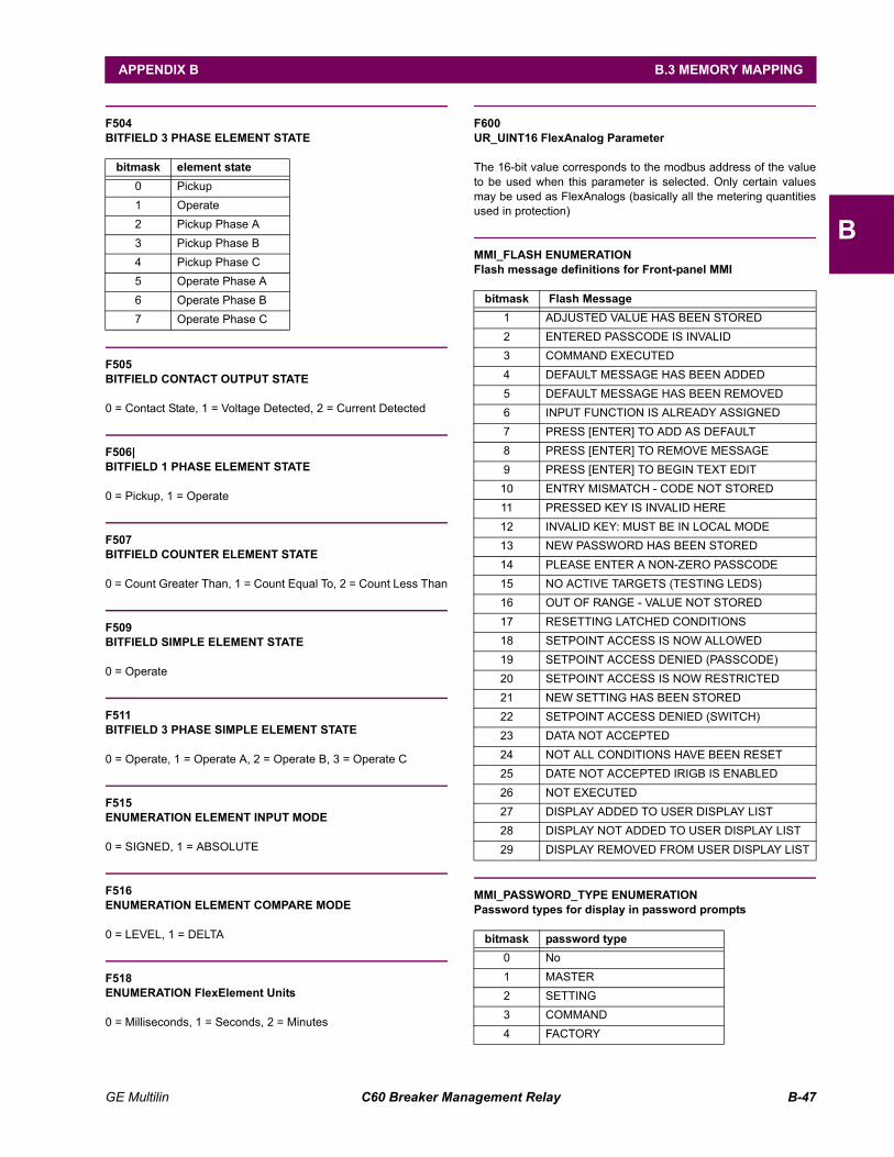
GE Multilin C60 Breaker Management Relay B-47
APPENDIX B B.3 MEMORY MAPPING
B
F504BITFIELD 3 PHASE ELEMENT STATE
F505BITFIELD CONTACT OUTPUT STATE
0 = Contact State, 1 = Voltage Detected, 2 = Current Detected
F506|BITFIELD 1 PHASE ELEMENT STATE
0 = Pickup, 1 = Operate
F507BITFIELD COUNTER ELEMENT STATE
0 = Count Greater Than, 1 = Count Equal To, 2 = Count Less Than
F509BITFIELD SIMPLE ELEMENT STATE
0 = Operate
F511BITFIELD 3 PHASE SIMPLE ELEMENT STATE
0 = Operate, 1 = Operate A, 2 = Operate B, 3 = Operate C
F515ENUMERATION ELEMENT INPUT MODE
0 = SIGNED, 1 = ABSOLUTE
F516ENUMERATION ELEMENT COMPARE MODE
0 = LEVEL, 1 = DELTA
F518ENUMERATION FlexElement Units
0 = Milliseconds, 1 = Seconds, 2 = Minutes
F600UR_UINT16 FlexAnalog Parameter
The 16-bit value corresponds to the modbus address of the valueto be used when this parameter is selected. Only certain valuesmay be used as FlexAnalogs (basically all the metering quantitiesused in protection)
MMI_FLASH ENUMERATIONFlash message definitions for Front-panel MMI
MMI_PASSWORD_TYPE ENUMERATIONPassword types for display in password prompts
bitmask element state0 Pickup1 Operate2 Pickup Phase A3 Pickup Phase B4 Pickup Phase C5 Operate Phase A6 Operate Phase B7 Operate Phase C
bitmask Flash Message1 ADJUSTED VALUE HAS BEEN STORED2 ENTERED PASSCODE IS INVALID 3 COMMAND EXECUTED 4 DEFAULT MESSAGE HAS BEEN ADDED 5 DEFAULT MESSAGE HAS BEEN REMOVED 6 INPUT FUNCTION IS ALREADY ASSIGNED 7 PRESS [ENTER] TO ADD AS DEFAULT 8 PRESS [ENTER] TO REMOVE MESSAGE 9 PRESS [ENTER] TO BEGIN TEXT EDIT
10 ENTRY MISMATCH - CODE NOT STORED 11 PRESSED KEY IS INVALID HERE 12 INVALID KEY: MUST BE IN LOCAL MODE 13 NEW PASSWORD HAS BEEN STORED 14 PLEASE ENTER A NON-ZERO PASSCODE 15 NO ACTIVE TARGETS (TESTING LEDS) 16 OUT OF RANGE - VALUE NOT STORED 17 RESETTING LATCHED CONDITIONS 18 SETPOINT ACCESS IS NOW ALLOWED 19 SETPOINT ACCESS DENIED (PASSCODE) 20 SETPOINT ACCESS IS NOW RESTRICTED 21 NEW SETTING HAS BEEN STORED 22 SETPOINT ACCESS DENIED (SWITCH) 23 DATA NOT ACCEPTED 24 NOT ALL CONDITIONS HAVE BEEN RESET 25 DATE NOT ACCEPTED IRIGB IS ENABLED 26 NOT EXECUTED 27 DISPLAY ADDED TO USER DISPLAY LIST 28 DISPLAY NOT ADDED TO USER DISPLAY LIST 29 DISPLAY REMOVED FROM USER DISPLAY LIST
bitmask password type0 No1 MASTER2 SETTING3 COMMAND4 FACTORY
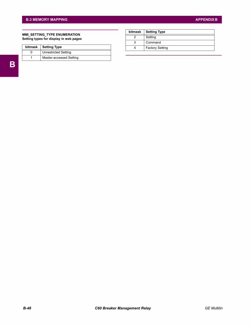
B-48 C60 Breaker Management Relay GE Multilin
B.3 MEMORY MAPPING APPENDIX B
B
MMI_SETTING_TYPE ENUMERATIONSetting types for display in web pages
bitmask Setting Type0 Unrestricted Setting1 Master-accessed Setting
2 Setting3 Command4 Factory Setting
bitmask Setting Type
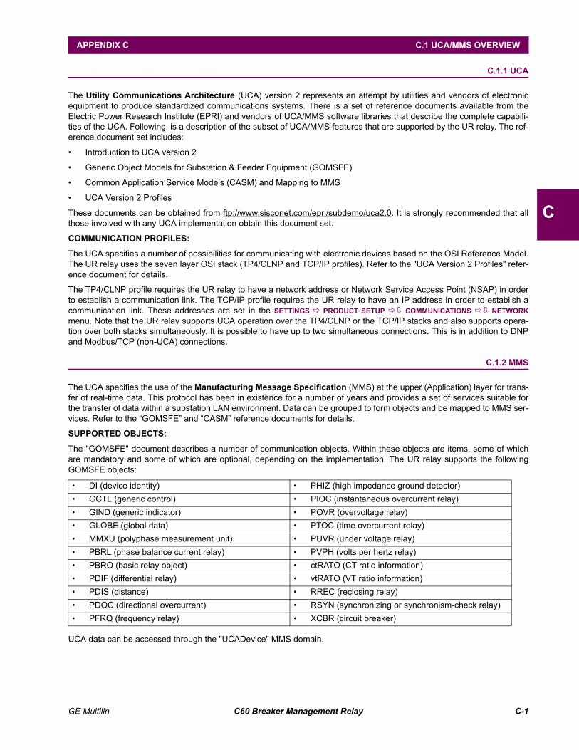
GE Multilin C60 Breaker Management Relay C-1
APPENDIX C C.1 UCA/MMS OVERVIEW
C
APPENDIX C UCA/MMSC.1 UCA/MMS OVERVIEW C.1.1 UCA
The Utility Communications Architecture (UCA) version 2 represents an attempt by utilities and vendors of electronicequipment to produce standardized communications systems. There is a set of reference documents available from theElectric Power Research Institute (EPRI) and vendors of UCA/MMS software libraries that describe the complete capabili-ties of the UCA. Following, is a description of the subset of UCA/MMS features that are supported by the UR relay. The ref-erence document set includes:
Introduction to UCA version 2
Generic Object Models for Substation & Feeder Equipment (GOMSFE)
Common Application Service Models (CASM) and Mapping to MMS
UCA Version 2 Profiles
These documents can be obtained from ftp://www.sisconet.com/epri/subdemo/uca2.0. It is strongly recommended that allthose involved with any UCA implementation obtain this document set.
COMMUNICATION PROFILES:
The UCA specifies a number of possibilities for communicating with electronic devices based on the OSI Reference Model.The UR relay uses the seven layer OSI stack (TP4/CLNP and TCP/IP profiles). Refer to the "UCA Version 2 Profiles" refer-ence document for details.
The TP4/CLNP profile requires the UR relay to have a network address or Network Service Access Point (NSAP) in orderto establish a communication link. The TCP/IP profile requires the UR relay to have an IP address in order to establish acommunication link. These addresses are set in the SETTINGS ! PRODUCT SETUP !" COMMUNICATIONS !" NETWORKmenu. Note that the UR relay supports UCA operation over the TP4/CLNP or the TCP/IP stacks and also supports opera-tion over both stacks simultaneously. It is possible to have up to two simultaneous connections. This is in addition to DNPand Modbus/TCP (non-UCA) connections.
C.1.2 MMS
The UCA specifies the use of the Manufacturing Message Specification (MMS) at the upper (Application) layer for trans-fer of real-time data. This protocol has been in existence for a number of years and provides a set of services suitable forthe transfer of data within a substation LAN environment. Data can be grouped to form objects and be mapped to MMS ser-vices. Refer to the GOMSFE and CASM reference documents for details.
SUPPORTED OBJECTS:
The "GOMSFE" document describes a number of communication objects. Within these objects are items, some of whichare mandatory and some of which are optional, depending on the implementation. The UR relay supports the followingGOMSFE objects:
UCA data can be accessed through the "UCADevice" MMS domain.
DI (device identity) PHIZ (high impedance ground detector) GCTL (generic control) PIOC (instantaneous overcurrent relay) GIND (generic indicator) POVR (overvoltage relay) GLOBE (global data) PTOC (time overcurrent relay) MMXU (polyphase measurement unit) PUVR (under voltage relay) PBRL (phase balance current relay) PVPH (volts per hertz relay) PBRO (basic relay object) ctRATO (CT ratio information) PDIF (differential relay) vtRATO (VT ratio information) PDIS (distance) RREC (reclosing relay) PDOC (directional overcurrent) RSYN (synchronizing or synchronism-check relay) PFRQ (frequency relay) XCBR (circuit breaker)
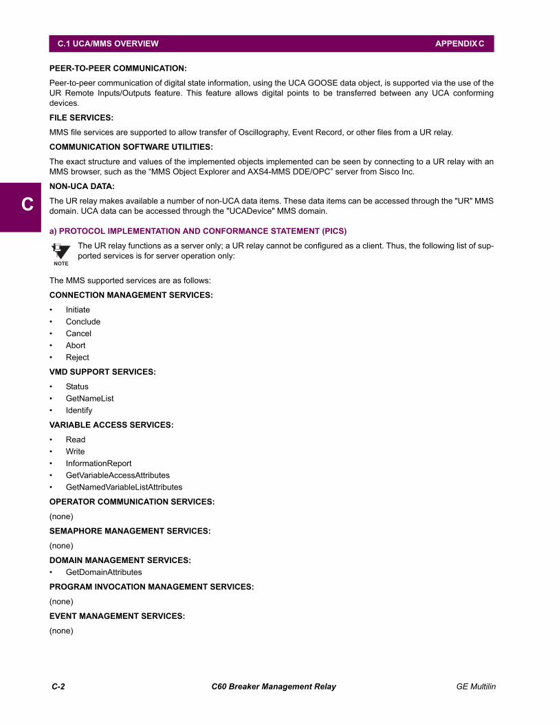
C-2 C60 Breaker Management Relay GE Multilin
C.1 UCA/MMS OVERVIEW APPENDIX C
C
PEER-TO-PEER COMMUNICATION:
Peer-to-peer communication of digital state information, using the UCA GOOSE data object, is supported via the use of theUR Remote Inputs/Outputs feature. This feature allows digital points to be transferred between any UCA conformingdevices.
FILE SERVICES:
MMS file services are supported to allow transfer of Oscillography, Event Record, or other files from a UR relay.
COMMUNICATION SOFTWARE UTILITIES:
The exact structure and values of the implemented objects implemented can be seen by connecting to a UR relay with anMMS browser, such as the MMS Object Explorer and AXS4-MMS DDE/OPC server from Sisco Inc.
NON-UCA DATA:
The UR relay makes available a number of non-UCA data items. These data items can be accessed through the "UR" MMSdomain. UCA data can be accessed through the "UCADevice" MMS domain.
a) PROTOCOL IMPLEMENTATION AND CONFORMANCE STATEMENT (PICS)
The UR relay functions as a server only; a UR relay cannot be configured as a client. Thus, the following list of sup-ported services is for server operation only:
The MMS supported services are as follows:
CONNECTION MANAGEMENT SERVICES:
Initiate Conclude Cancel Abort Reject
VMD SUPPORT SERVICES:
Status GetNameList Identify
VARIABLE ACCESS SERVICES:
Read Write InformationReport GetVariableAccessAttributes GetNamedVariableListAttributes
OPERATOR COMMUNICATION SERVICES:
(none)
SEMAPHORE MANAGEMENT SERVICES:
(none)
DOMAIN MANAGEMENT SERVICES: GetDomainAttributes
PROGRAM INVOCATION MANAGEMENT SERVICES:
(none)
EVENT MANAGEMENT SERVICES:
(none)
NOTE
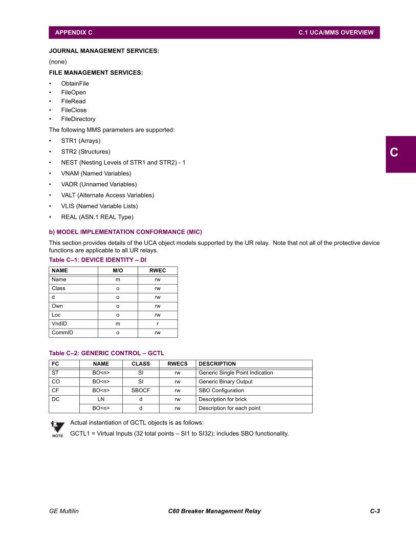
GE Multilin C60 Breaker Management Relay C-3
APPENDIX C C.1 UCA/MMS OVERVIEW
C
JOURNAL MANAGEMENT SERVICES:
(none)
FILE MANAGEMENT SERVICES:
ObtainFile FileOpen FileRead FileClose FileDirectory
The following MMS parameters are supported:
STR1 (Arrays)
STR2 (Structures)
NEST (Nesting Levels of STR1 and STR2) - 1
VNAM (Named Variables)
VADR (Unnamed Variables)
VALT (Alternate Access Variables)
VLIS (Named Variable Lists)
REAL (ASN.1 REAL Type)
b) MODEL IMPLEMENTATION CONFORMANCE (MIC)
This section provides details of the UCA object models supported by the UR relay. Note that not all of the protective devicefunctions are applicable to all UR relays.
Actual instantiation of GCTL objects is as follows:
GCTL1 = Virtual Inputs (32 total points SI1 to SI32); includes SBO functionality.
Table C1: DEVICE IDENTITY DINAME M/O RWECName m rwClass o rwd o rwOwn o rwLoc o rwVndID m rCommID o rw
Table C2: GENERIC CONTROL GCTLFC NAME CLASS RWECS DESCRIPTIONST BO<n> SI rw Generic Single Point IndicationCO BO<n> SI rw Generic Binary OutputCF BO<n> SBOCF rw SBO ConfigurationDC LN d rw Description for brick
BO<n> d rw Description for each point
NOTE
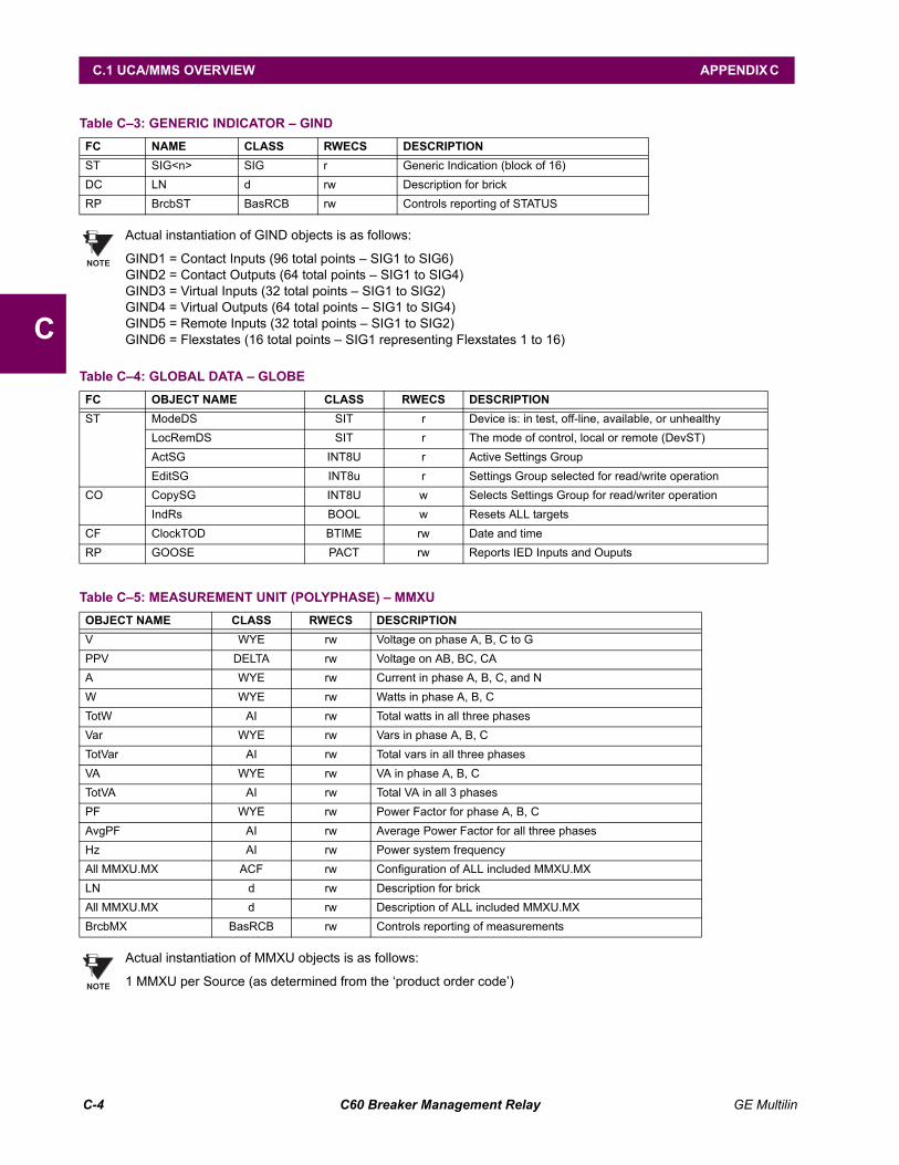
C-4 C60 Breaker Management Relay GE Multilin
C.1 UCA/MMS OVERVIEW APPENDIX C
C
Actual instantiation of GIND objects is as follows:
GIND1 = Contact Inputs (96 total points SIG1 to SIG6)GIND2 = Contact Outputs (64 total points SIG1 to SIG4)GIND3 = Virtual Inputs (32 total points SIG1 to SIG2)GIND4 = Virtual Outputs (64 total points SIG1 to SIG4)GIND5 = Remote Inputs (32 total points SIG1 to SIG2)GIND6 = Flexstates (16 total points SIG1 representing Flexstates 1 to 16)
Actual instantiation of MMXU objects is as follows:
1 MMXU per Source (as determined from the product order code)
Table C3: GENERIC INDICATOR GINDFC NAME CLASS RWECS DESCRIPTIONST SIG<n> SIG r Generic Indication (block of 16)DC LN d rw Description for brickRP BrcbST BasRCB rw Controls reporting of STATUS
Table C4: GLOBAL DATA GLOBEFC OBJECT NAME CLASS RWECS DESCRIPTIONST ModeDS SIT r Device is: in test, off-line, available, or unhealthy
LocRemDS SIT r The mode of control, local or remote (DevST)ActSG INT8U r Active Settings GroupEditSG INT8u r Settings Group selected for read/write operation
CO CopySG INT8U w Selects Settings Group for read/writer operationIndRs BOOL w Resets ALL targets
CF ClockTOD BTIME rw Date and timeRP GOOSE PACT rw Reports IED Inputs and Ouputs
Table C5: MEASUREMENT UNIT (POLYPHASE) MMXUOBJECT NAME CLASS RWECS DESCRIPTIONV WYE rw Voltage on phase A, B, C to GPPV DELTA rw Voltage on AB, BC, CAA WYE rw Current in phase A, B, C, and NW WYE rw Watts in phase A, B, CTotW AI rw Total watts in all three phasesVar WYE rw Vars in phase A, B, CTotVar AI rw Total vars in all three phasesVA WYE rw VA in phase A, B, CTotVA AI rw Total VA in all 3 phasesPF WYE rw Power Factor for phase A, B, CAvgPF AI rw Average Power Factor for all three phasesHz AI rw Power system frequencyAll MMXU.MX ACF rw Configuration of ALL included MMXU.MXLN d rw Description for brickAll MMXU.MX d rw Description of ALL included MMXU.MXBrcbMX BasRCB rw Controls reporting of measurements
NOTE
NOTE
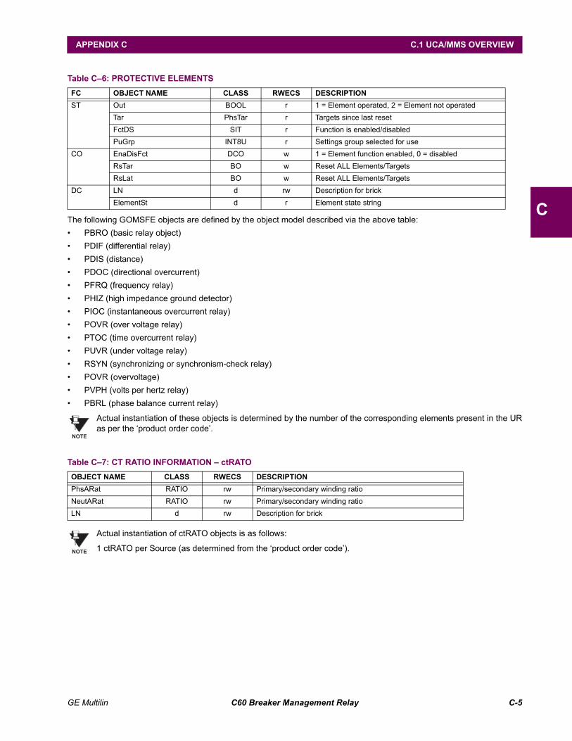
GE Multilin C60 Breaker Management Relay C-5
APPENDIX C C.1 UCA/MMS OVERVIEW
CThe following GOMSFE objects are defined by the object model described via the above table: PBRO (basic relay object) PDIF (differential relay) PDIS (distance) PDOC (directional overcurrent) PFRQ (frequency relay) PHIZ (high impedance ground detector) PIOC (instantaneous overcurrent relay) POVR (over voltage relay) PTOC (time overcurrent relay) PUVR (under voltage relay) RSYN (synchronizing or synchronism-check relay) POVR (overvoltage) PVPH (volts per hertz relay) PBRL (phase balance current relay)
Actual instantiation of these objects is determined by the number of the corresponding elements present in the URas per the product order code.
Actual instantiation of ctRATO objects is as follows:
1 ctRATO per Source (as determined from the product order code).
Table C6: PROTECTIVE ELEMENTSFC OBJECT NAME CLASS RWECS DESCRIPTIONST Out BOOL r 1 = Element operated, 2 = Element not operated
Tar PhsTar r Targets since last resetFctDS SIT r Function is enabled/disabledPuGrp INT8U r Settings group selected for use
CO EnaDisFct DCO w 1 = Element function enabled, 0 = disabledRsTar BO w Reset ALL Elements/TargetsRsLat BO w Reset ALL Elements/Targets
DC LN d rw Description for brickElementSt d r Element state string
Table C7: CT RATIO INFORMATION ctRATOOBJECT NAME CLASS RWECS DESCRIPTIONPhsARat RATIO rw Primary/secondary winding ratioNeutARat RATIO rw Primary/secondary winding ratioLN d rw Description for brick
NOTE
NOTE
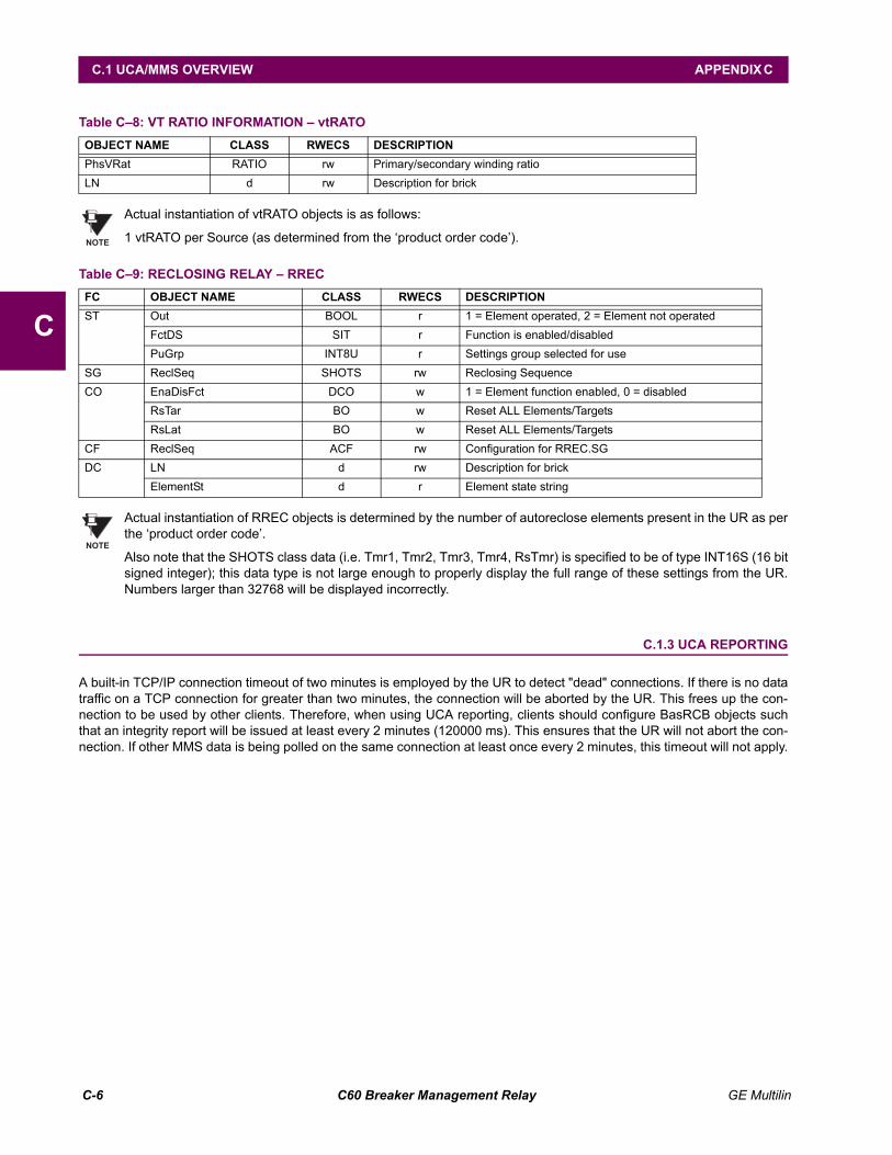
C-6 C60 Breaker Management Relay GE Multilin
C.1 UCA/MMS OVERVIEW APPENDIX C
C
Actual instantiation of vtRATO objects is as follows:
1 vtRATO per Source (as determined from the product order code).
Actual instantiation of RREC objects is determined by the number of autoreclose elements present in the UR as perthe product order code.
Also note that the SHOTS class data (i.e. Tmr1, Tmr2, Tmr3, Tmr4, RsTmr) is specified to be of type INT16S (16 bitsigned integer); this data type is not large enough to properly display the full range of these settings from the UR.Numbers larger than 32768 will be displayed incorrectly.
C.1.3 UCA REPORTING
A built-in TCP/IP connection timeout of two minutes is employed by the UR to detect "dead" connections. If there is no datatraffic on a TCP connection for greater than two minutes, the connection will be aborted by the UR. This frees up the con-nection to be used by other clients. Therefore, when using UCA reporting, clients should configure BasRCB objects suchthat an integrity report will be issued at least every 2 minutes (120000 ms). This ensures that the UR will not abort the con-nection. If other MMS data is being polled on the same connection at least once every 2 minutes, this timeout will not apply.
Table C8: VT RATIO INFORMATION vtRATOOBJECT NAME CLASS RWECS DESCRIPTIONPhsVRat RATIO rw Primary/secondary winding ratioLN d rw Description for brick
Table C9: RECLOSING RELAY RRECFC OBJECT NAME CLASS RWECS DESCRIPTIONST Out BOOL r 1 = Element operated, 2 = Element not operated
FctDS SIT r Function is enabled/disabledPuGrp INT8U r Settings group selected for use
SG ReclSeq SHOTS rw Reclosing SequenceCO EnaDisFct DCO w 1 = Element function enabled, 0 = disabled
RsTar BO w Reset ALL Elements/TargetsRsLat BO w Reset ALL Elements/Targets
CF ReclSeq ACF rw Configuration for RREC.SGDC LN d rw Description for brick
ElementSt d r Element state string
NOTE
NOTE
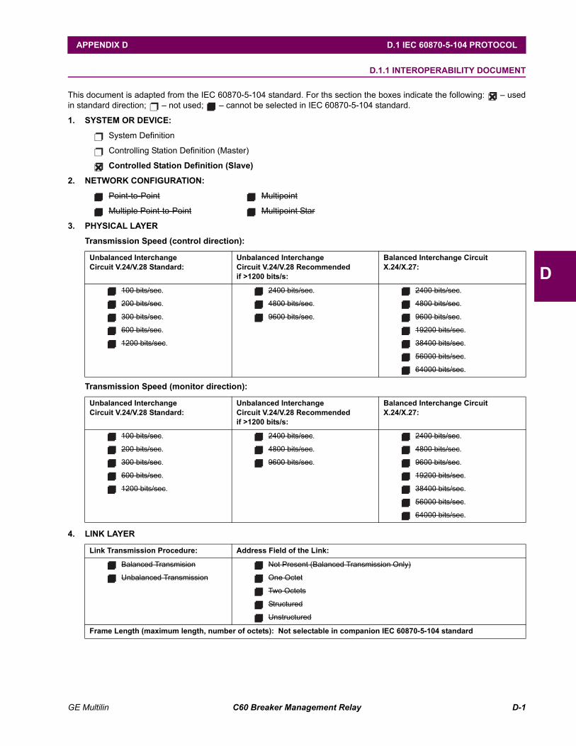
GE Multilin C60 Breaker Management Relay D-1
APPENDIX D D.1 IEC 60870-5-104 PROTOCOL
D
APPENDIX D IEC 60870-5-104D.1 IEC 60870-5-104 PROTOCOL D.1.1 INTEROPERABILITY DOCUMENT
This document is adapted from the IEC 60870-5-104 standard. For ths section the boxes indicate the following: usedin standard direction; not used; cannot be selected in IEC 60870-5-104 standard.
1. SYSTEM OR DEVICE:
System Definition
Controlling Station Definition (Master)
Controlled Station Definition (Slave)
2. NETWORK CONFIGURATION:
Point-to-Point Multipoint
Multiple Point-to-Point Multipoint Star
3. PHYSICAL LAYER
Transmission Speed (control direction):
Transmission Speed (monitor direction):
4. LINK LAYER
Unbalanced InterchangeCircuit V.24/V.28 Standard:
Unbalanced InterchangeCircuit V.24/V.28 Recommendedif >1200 bits/s:
Balanced Interchange CircuitX.24/X.27:
100 bits/sec.
200 bits/sec.
300 bits/sec.
600 bits/sec.
1200 bits/sec.
2400 bits/sec.
4800 bits/sec.
9600 bits/sec.
2400 bits/sec.
4800 bits/sec.
9600 bits/sec.
19200 bits/sec.
38400 bits/sec.
56000 bits/sec.
64000 bits/sec.
Link Transmission Procedure: Address Field of the Link:
Balanced Transmision
Unbalanced Transmission
Not Present (Balanced Transmission Only)
One Octet
Two Octets
Structured
Unstructured
Frame Length (maximum length, number of octets): Not selectable in companion IEC 60870-5-104 standard
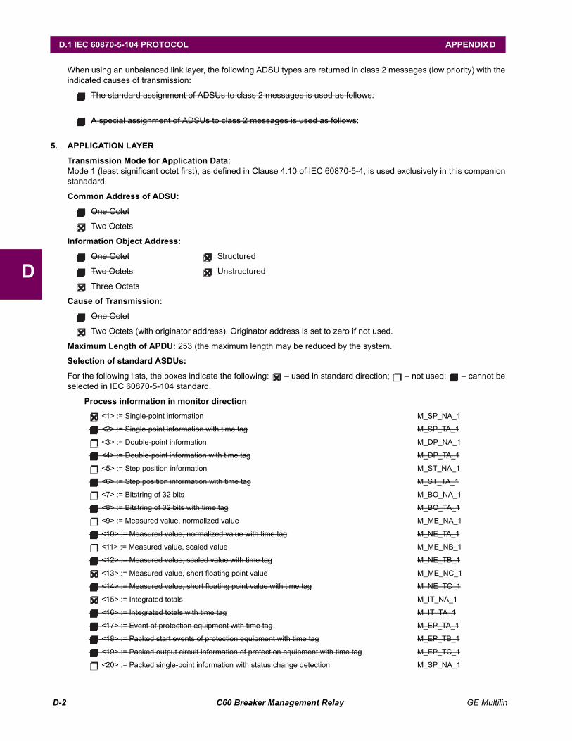
D-2 C60 Breaker Management Relay GE Multilin
D.1 IEC 60870-5-104 PROTOCOL APPENDIX D
D
When using an unbalanced link layer, the following ADSU types are returned in class 2 messages (low priority) with theindicated causes of transmission:
The standard assignment of ADSUs to class 2 messages is used as follows:
A special assignment of ADSUs to class 2 messages is used as follows:
5. APPLICATION LAYER
Transmission Mode for Application Data:Mode 1 (least significant octet first), as defined in Clause 4.10 of IEC 60870-5-4, is used exclusively in this companionstanadard.
Common Address of ADSU:
One Octet
Two Octets
Information Object Address:
One Octet Structured
Two Octets Unstructured
Three Octets
Cause of Transmission:
One Octet
Two Octets (with originator address). Originator address is set to zero if not used.
Maximum Length of APDU: 253 (the maximum length may be reduced by the system.
Selection of standard ASDUs:
For the following lists, the boxes indicate the following: used in standard direction; not used; cannot beselected in IEC 60870-5-104 standard.
Process information in monitor direction <1> := Single-point information M_SP_NA_1
<2> := Single-point information with time tag M_SP_TA_1
<3> := Double-point information M_DP_NA_1
<4> := Double-point information with time tag M_DP_TA_1
<5> := Step position information M_ST_NA_1
<6> := Step position information with time tag M_ST_TA_1
<7> := Bitstring of 32 bits M_BO_NA_1
<8> := Bitstring of 32 bits with time tag M_BO_TA_1
<9> := Measured value, normalized value M_ME_NA_1
<10> := Measured value, normalized value with time tag M_NE_TA_1
<11> := Measured value, scaled value M_ME_NB_1
<12> := Measured value, scaled value with time tag M_NE_TB_1
<13> := Measured value, short floating point value M_ME_NC_1
<14> := Measured value, short floating point value with time tag M_NE_TC_1
<15> := Integrated totals M_IT_NA_1
<16> := Integrated totals with time tag M_IT_TA_1
<17> := Event of protection equipment with time tag M_EP_TA_1
<18> := Packed start events of protection equipment with time tag M_EP_TB_1
<19> := Packed output circuit information of protection equipment with time tag M_EP_TC_1
<20> := Packed single-point information with status change detection M_SP_NA_1
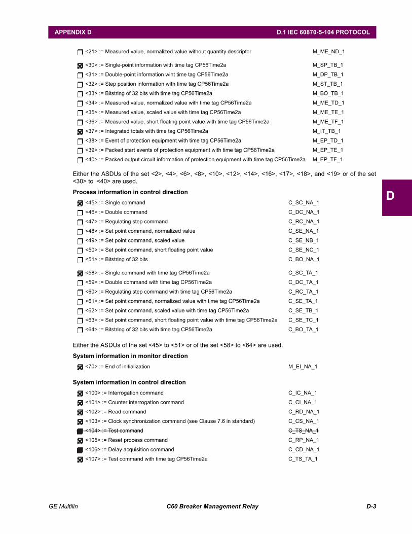
GE Multilin C60 Breaker Management Relay D-3
APPENDIX D D.1 IEC 60870-5-104 PROTOCOL
D
Either the ASDUs of the set <2>, <4>, <6>, <8>, <10>, <12>, <14>, <16>, <17>, <18>, and <19> or of the set<30> to <40> are used.
Process information in control direction
Either the ASDUs of the set <45> to <51> or of the set <58> to <64> are used.
System information in monitor direction
System information in control direction
<21> := Measured value, normalized value without quantity descriptor M_ME_ND_1
<30> := Single-point information with time tag CP56Time2a M_SP_TB_1
<31> := Double-point information wiht time tag CP56Time2a M_DP_TB_1
<32> := Step position information with time tag CP56Time2a M_ST_TB_1
<33> := Bitstring of 32 bits with time tag CP56Time2a M_BO_TB_1
<34> := Measured value, normalized value with time tag CP56Time2a M_ME_TD_1
<35> := Measured value, scaled value with time tag CP56Time2a M_ME_TE_1
<36> := Measured value, short floating point value with time tag CP56Time2a M_ME_TF_1
<37> := Integrated totals with time tag CP56Time2a M_IT_TB_1
<38> := Event of protection equipment with time tag CP56Time2a M_EP_TD_1
<39> := Packed start events of protection equipment with time tag CP56Time2a M_EP_TE_1
<40> := Packed output circuit information of protection equipment with time tag CP56Time2a M_EP_TF_1
<45> := Single command C_SC_NA_1
<46> := Double command C_DC_NA_1
<47> := Regulating step command C_RC_NA_1
<48> := Set point command, normalized value C_SE_NA_1
<49> := Set point command, scaled value C_SE_NB_1
<50> := Set point command, short floating point value C_SE_NC_1
<51> := Bitstring of 32 bits C_BO_NA_1
<58> := Single command with time tag CP56Time2a C_SC_TA_1
<59> := Double command with time tag CP56Time2a C_DC_TA_1
<60> := Regulating step command with time tag CP56Time2a C_RC_TA_1
<61> := Set point command, normalized value with time tag CP56Time2a C_SE_TA_1
<62> := Set point command, scaled value with time tag CP56Time2a C_SE_TB_1
<63> := Set point command, short floating point value with time tag CP56Time2a C_SE_TC_1
<64> := Bitstring of 32 bits with time tag CP56Time2a C_BO_TA_1
<70> := End of initialization M_EI_NA_1
<100> := Interrogation command C_IC_NA_1
<101> := Counter interrogation command C_CI_NA_1
<102> := Read command C_RD_NA_1
<103> := Clock synchronization command (see Clause 7.6 in standard) C_CS_NA_1
<104> := Test command C_TS_NA_1
<105> := Reset process command C_RP_NA_1
<106> := Delay acquisition command C_CD_NA_1
<107> := Test command with time tag CP56Time2a C_TS_TA_1
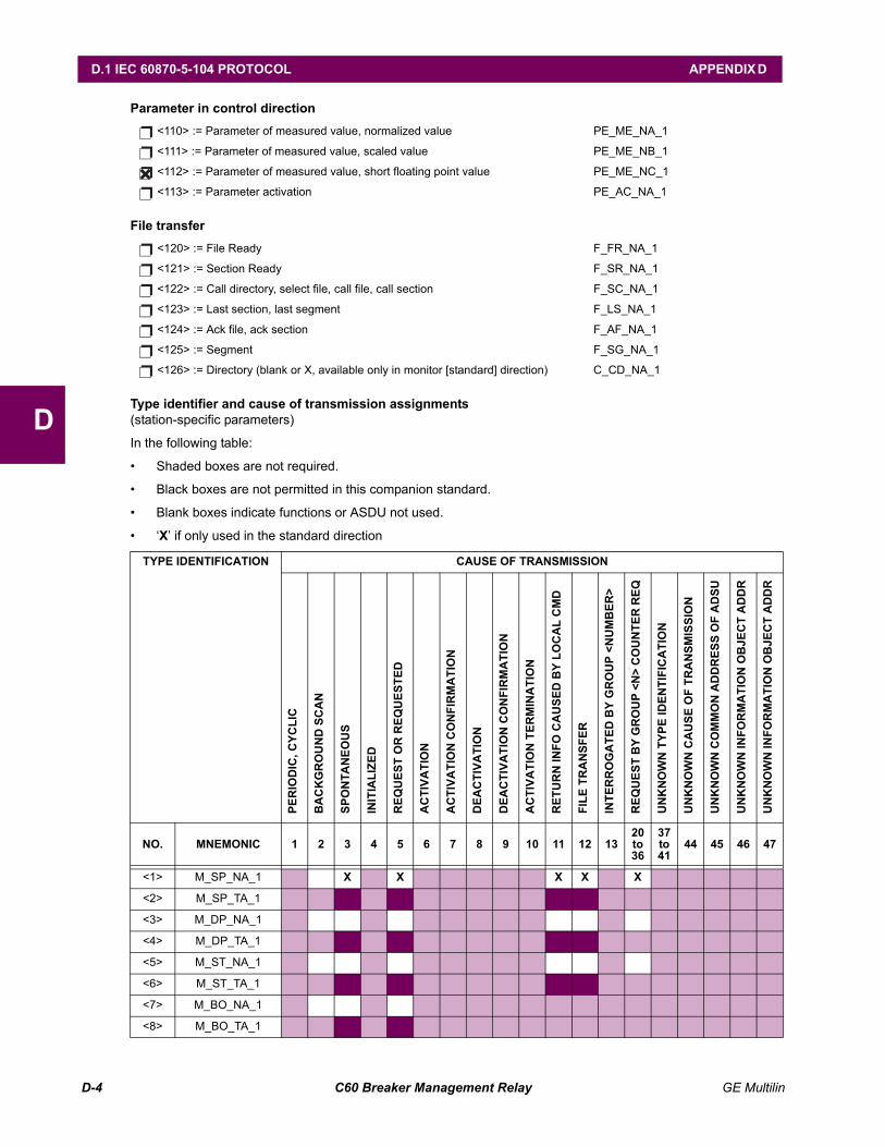
D-4 C60 Breaker Management Relay GE Multilin
D.1 IEC 60870-5-104 PROTOCOL APPENDIX D
D
Parameter in control direction
File transfer
Type identifier and cause of transmission assignments(station-specific parameters)
In the following table:
Shaded boxes are not required.
Black boxes are not permitted in this companion standard.
Blank boxes indicate functions or ASDU not used.
X if only used in the standard direction
<110> := Parameter of measured value, normalized value PE_ME_NA_1
<111> := Parameter of measured value, scaled value PE_ME_NB_1
<112> := Parameter of measured value, short floating point value PE_ME_NC_1
<113> := Parameter activation PE_AC_NA_1
<120> := File Ready F_FR_NA_1
<121> := Section Ready F_SR_NA_1
<122> := Call directory, select file, call file, call section F_SC_NA_1
<123> := Last section, last segment F_LS_NA_1
<124> := Ack file, ack section F_AF_NA_1
<125> := Segment F_SG_NA_1
<126> := Directory (blank or X, available only in monitor [standard] direction) C_CD_NA_1
TYPE IDENTIFICATION CAUSE OF TRANSMISSION
NO. MNEMONIC 1 2 3 4 5 6 7 8 9 10 11 12 1320 to 36
37 to 41
44 45 46 47
<1> M_SP_NA_1 X X X X X
<2> M_SP_TA_1
<3> M_DP_NA_1
<4> M_DP_TA_1
<5> M_ST_NA_1
<6> M_ST_TA_1
<7> M_BO_NA_1
<8> M_BO_TA_1
PER
IOD
IC, C
YCLI
C
BA
CK
GR
OU
ND
SC
AN
SPO
NTA
NEO
US
INIT
IALI
ZED
REQ
UES
T O
R R
EQU
ESTE
D
AC
TIVA
TIO
N
AC
TIVA
TIO
N C
ON
FIR
MA
TIO
N
DEA
CTI
VATI
ON
DEA
CTI
VATI
ON
CO
NFI
RM
ATI
ON
AC
TIVA
TIO
N T
ERM
INA
TIO
N
RET
UR
N IN
FO C
AU
SED
BY
LOC
AL
CM
D
FILE
TR
AN
SFER
INTE
RR
OG
ATE
D B
Y G
RO
UP
<NU
MB
ER>
REQ
UES
T B
Y G
RO
UP
<N>
CO
UN
TER
REQ
UN
KN
OW
N T
YPE
IDEN
TIFI
CA
TIO
N
UN
KN
OW
N C
AU
SE O
F TR
AN
SMIS
SIO
N
UN
KN
OW
N C
OM
MO
N A
DD
RES
S O
F A
DSU
UN
KN
OW
N IN
FOR
MA
TIO
N O
BJE
CT
AD
DR
UN
KN
OW
N IN
FOR
MA
TIO
N O
BJE
CT
AD
DR
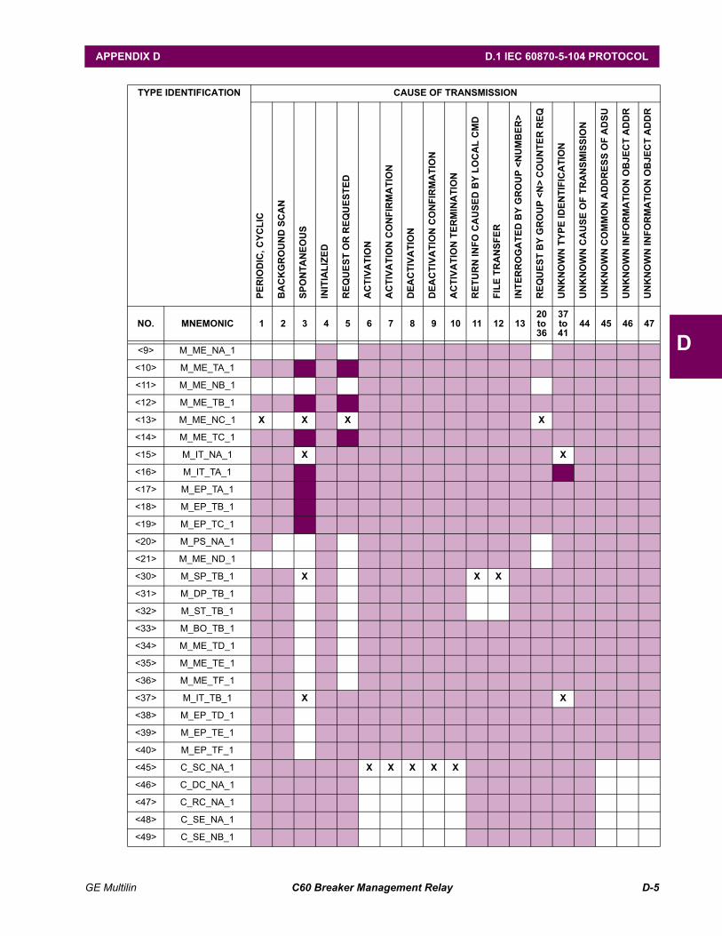
GE Multilin C60 Breaker Management Relay D-5
APPENDIX D D.1 IEC 60870-5-104 PROTOCOL
D<9> M_ME_NA_1
<10> M_ME_TA_1
<11> M_ME_NB_1
<12> M_ME_TB_1
<13> M_ME_NC_1 X X X X
<14> M_ME_TC_1
<15> M_IT_NA_1 X X
<16> M_IT_TA_1
<17> M_EP_TA_1
<18> M_EP_TB_1
<19> M_EP_TC_1
<20> M_PS_NA_1
<21> M_ME_ND_1
<30> M_SP_TB_1 X X X
<31> M_DP_TB_1
<32> M_ST_TB_1
<33> M_BO_TB_1
<34> M_ME_TD_1
<35> M_ME_TE_1
<36> M_ME_TF_1
<37> M_IT_TB_1 X X
<38> M_EP_TD_1
<39> M_EP_TE_1
<40> M_EP_TF_1
<45> C_SC_NA_1 X X X X X
<46> C_DC_NA_1
<47> C_RC_NA_1
<48> C_SE_NA_1
<49> C_SE_NB_1
TYPE IDENTIFICATION CAUSE OF TRANSMISSION
NO. MNEMONIC 1 2 3 4 5 6 7 8 9 10 11 12 1320 to 36
37 to 41
44 45 46 47
PER
IOD
IC, C
YCLI
C
BA
CK
GR
OU
ND
SC
AN
SPO
NTA
NEO
US
INIT
IALI
ZED
REQ
UES
T O
R R
EQU
ESTE
D
AC
TIVA
TIO
N
AC
TIVA
TIO
N C
ON
FIR
MA
TIO
N
DEA
CTI
VATI
ON
DEA
CTI
VATI
ON
CO
NFI
RM
ATI
ON
AC
TIVA
TIO
N T
ERM
INA
TIO
N
RET
UR
N IN
FO C
AU
SED
BY
LOC
AL
CM
D
FILE
TR
AN
SFER
INTE
RR
OG
ATE
D B
Y G
RO
UP
<NU
MB
ER>
REQ
UES
T B
Y G
RO
UP
<N>
CO
UN
TER
REQ
UN
KN
OW
N T
YPE
IDEN
TIFI
CA
TIO
N
UN
KN
OW
N C
AU
SE O
F TR
AN
SMIS
SIO
N
UN
KN
OW
N C
OM
MO
N A
DD
RES
S O
F A
DSU
UN
KN
OW
N IN
FOR
MA
TIO
N O
BJE
CT
AD
DR
UN
KN
OW
N IN
FOR
MA
TIO
N O
BJE
CT
AD
DR
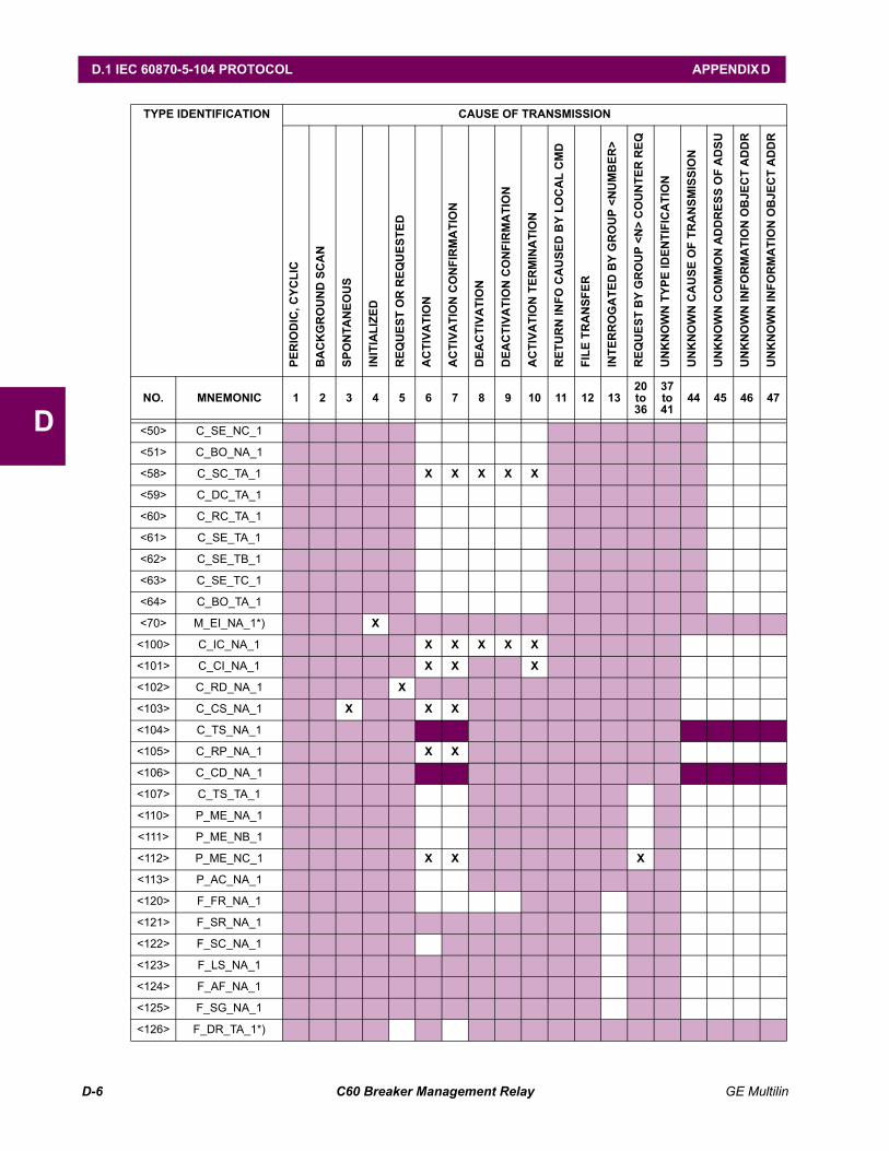
D-6 C60 Breaker Management Relay GE Multilin
D.1 IEC 60870-5-104 PROTOCOL APPENDIX D
D <50> C_SE_NC_1
<51> C_BO_NA_1
<58> C_SC_TA_1 X X X X X
<59> C_DC_TA_1
<60> C_RC_TA_1
<61> C_SE_TA_1
<62> C_SE_TB_1
<63> C_SE_TC_1
<64> C_BO_TA_1
<70> M_EI_NA_1*) X
<100> C_IC_NA_1 X X X X X
<101> C_CI_NA_1 X X X
<102> C_RD_NA_1 X
<103> C_CS_NA_1 X X X
<104> C_TS_NA_1
<105> C_RP_NA_1 X X
<106> C_CD_NA_1
<107> C_TS_TA_1
<110> P_ME_NA_1
<111> P_ME_NB_1
<112> P_ME_NC_1 X X X
<113> P_AC_NA_1
<120> F_FR_NA_1
<121> F_SR_NA_1
<122> F_SC_NA_1
<123> F_LS_NA_1
<124> F_AF_NA_1
<125> F_SG_NA_1
<126> F_DR_TA_1*)
TYPE IDENTIFICATION CAUSE OF TRANSMISSION
NO. MNEMONIC 1 2 3 4 5 6 7 8 9 10 11 12 1320 to 36
37 to 41
44 45 46 47
PER
IOD
IC, C
YCLI
C
BA
CK
GR
OU
ND
SC
AN
SPO
NTA
NEO
US
INIT
IALI
ZED
REQ
UES
T O
R R
EQU
ESTE
D
AC
TIVA
TIO
N
AC
TIVA
TIO
N C
ON
FIR
MA
TIO
N
DEA
CTI
VATI
ON
DEA
CTI
VATI
ON
CO
NFI
RM
ATI
ON
AC
TIVA
TIO
N T
ERM
INA
TIO
N
RET
UR
N IN
FO C
AU
SED
BY
LOC
AL
CM
D
FILE
TR
AN
SFER
INTE
RR
OG
ATE
D B
Y G
RO
UP
<NU
MB
ER>
REQ
UES
T B
Y G
RO
UP
<N>
CO
UN
TER
REQ
UN
KN
OW
N T
YPE
IDEN
TIFI
CA
TIO
N
UN
KN
OW
N C
AU
SE O
F TR
AN
SMIS
SIO
N
UN
KN
OW
N C
OM
MO
N A
DD
RES
S O
F A
DSU
UN
KN
OW
N IN
FOR
MA
TIO
N O
BJE
CT
AD
DR
UN
KN
OW
N IN
FOR
MA
TIO
N O
BJE
CT
AD
DR
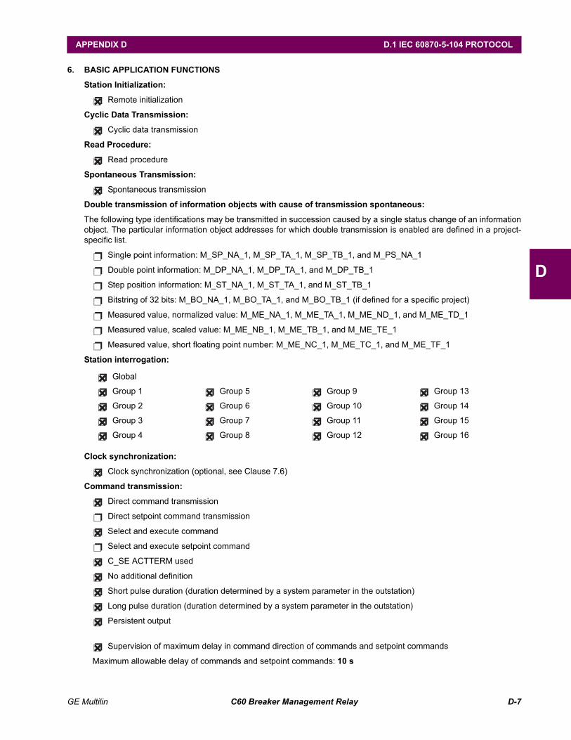
GE Multilin C60 Breaker Management Relay D-7
APPENDIX D D.1 IEC 60870-5-104 PROTOCOL
D
6. BASIC APPLICATION FUNCTIONS
Station Initialization:
Remote initialization
Cyclic Data Transmission:
Cyclic data transmission
Read Procedure:
Read procedure
Spontaneous Transmission:
Spontaneous transmission
Double transmission of information objects with cause of transmission spontaneous:
The following type identifications may be transmitted in succession caused by a single status change of an informationobject. The particular information object addresses for which double transmission is enabled are defined in a project-specific list.
Single point information: M_SP_NA_1, M_SP_TA_1, M_SP_TB_1, and M_PS_NA_1
Double point information: M_DP_NA_1, M_DP_TA_1, and M_DP_TB_1
Step position information: M_ST_NA_1, M_ST_TA_1, and M_ST_TB_1
Bitstring of 32 bits: M_BO_NA_1, M_BO_TA_1, and M_BO_TB_1 (if defined for a specific project)
Measured value, normalized value: M_ME_NA_1, M_ME_TA_1, M_ME_ND_1, and M_ME_TD_1
Measured value, scaled value: M_ME_NB_1, M_ME_TB_1, and M_ME_TE_1
Measured value, short floating point number: M_ME_NC_1, M_ME_TC_1, and M_ME_TF_1
Station interrogation:
Clock synchronization:
Clock synchronization (optional, see Clause 7.6)
Command transmission:
Direct command transmission
Direct setpoint command transmission
Select and execute command
Select and execute setpoint command
C_SE ACTTERM used
No additional definition
Short pulse duration (duration determined by a system parameter in the outstation)
Long pulse duration (duration determined by a system parameter in the outstation)
Persistent output
Supervision of maximum delay in command direction of commands and setpoint commands
Maximum allowable delay of commands and setpoint commands: 10 s
Global
Group 1 Group 5 Group 9 Group 13
Group 2 Group 6 Group 10 Group 14
Group 3 Group 7 Group 11 Group 15
Group 4 Group 8 Group 12 Group 16
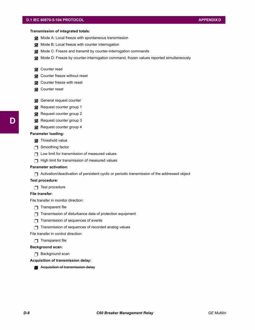
D-8 C60 Breaker Management Relay GE Multilin
D.1 IEC 60870-5-104 PROTOCOL APPENDIX D
D
Transmission of integrated totals:
Mode A: Local freeze with spontaneous transmission
Mode B: Local freeze with counter interrogation
Mode C: Freeze and transmit by counter-interrogation commands
Mode D: Freeze by counter-interrogation command, frozen values reported simultaneously
Counter read
Counter freeze without reset
Counter freeze with reset
Counter reset
General request counter
Request counter group 1
Request counter group 2
Request counter group 3
Request counter group 4
Parameter loading:
Threshold value
Smoothing factor
Low limit for transmission of measured values
High limit for transmission of measured values
Parameter activation:
Activation/deactivation of persistent cyclic or periodic transmission of the addressed object
Test procedure:
Test procedure
File transfer:
File transfer in monitor direction:
Transparent file
Transmission of disturbance data of protection equipment
Transmission of sequences of events
Transmission of sequences of recorded analog values
File transfer in control direction:
Transparent file
Background scan:
Background scan
Acquisition of transmission delay:
Acquisition of transmission delay
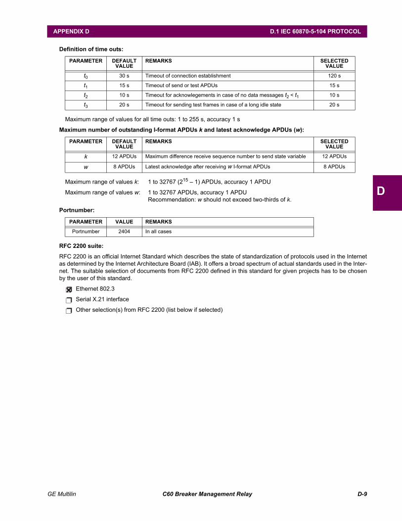
GE Multilin C60 Breaker Management Relay D-9
APPENDIX D D.1 IEC 60870-5-104 PROTOCOL
D
Definition of time outs:
Maximum range of values for all time outs: 1 to 255 s, accuracy 1 s
Maximum number of outstanding I-format APDUs k and latest acknowledge APDUs (w):
Maximum range of values k: 1 to 32767 (215 1) APDUs, accuracy 1 APDU
Maximum range of values w: 1 to 32767 APDUs, accuracy 1 APDURecommendation: w should not exceed two-thirds of k.
Portnumber:
RFC 2200 suite:
RFC 2200 is an official Internet Standard which describes the state of standardization of protocols used in the Internetas determined by the Internet Architecture Board (IAB). It offers a broad spectrum of actual standards used in the Inter-net. The suitable selection of documents from RFC 2200 defined in this standard for given projects has to be chosenby the user of this standard.
Ethernet 802.3
Serial X.21 interface
Other selection(s) from RFC 2200 (list below if selected)
PARAMETER DEFAULT VALUE
REMARKS SELECTED VALUE
t0 30 s Timeout of connection establishment 120 s
t1 15 s Timeout of send or test APDUs 15 s
t2 10 s Timeout for acknowlegements in case of no data messages t2 < t1 10 s
t3 20 s Timeout for sending test frames in case of a long idle state 20 s
PARAMETER DEFAULT VALUE
REMARKS SELECTED VALUE
k 12 APDUs Maximum difference receive sequence number to send state variable 12 APDUs
w 8 APDUs Latest acknowledge after receiving w I-format APDUs 8 APDUs
PARAMETER VALUE REMARKS
Portnumber 2404 In all cases
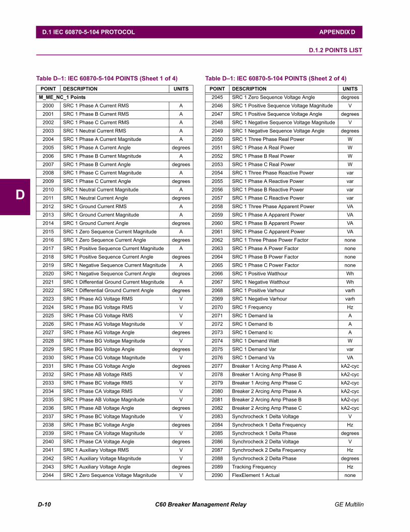
D-10 C60 Breaker Management Relay GE Multilin
D.1 IEC 60870-5-104 PROTOCOL APPENDIX D
D
D.1.2 POINTS LIST
Table D1: IEC 60870-5-104 POINTS (Sheet 1 of 4)POINT DESCRIPTION UNITS
M_ME_NC_1 Points2000 SRC 1 Phase A Current RMS A
2001 SRC 1 Phase B Current RMS A
2002 SRC 1 Phase C Current RMS A
2003 SRC 1 Neutral Current RMS A
2004 SRC 1 Phase A Current Magnitude A
2005 SRC 1 Phase A Current Angle degrees
2006 SRC 1 Phase B Current Magnitude A
2007 SRC 1 Phase B Current Angle degrees
2008 SRC 1 Phase C Current Magnitude A
2009 SRC 1 Phase C Current Angle degrees
2010 SRC 1 Neutral Current Magnitude A
2011 SRC 1 Neutral Current Angle degrees
2012 SRC 1 Ground Current RMS A
2013 SRC 1 Ground Current Magnitude A
2014 SRC 1 Ground Current Angle degrees
2015 SRC 1 Zero Sequence Current Magnitude A
2016 SRC 1 Zero Sequence Current Angle degrees
2017 SRC 1 Positive Sequence Current Magnitude A
2018 SRC 1 Positive Sequence Current Angle degrees
2019 SRC 1 Negative Sequence Current Magnitude A
2020 SRC 1 Negative Sequence Current Angle degrees
2021 SRC 1 Differential Ground Current Magnitude A
2022 SRC 1 Differential Ground Current Angle degrees
2023 SRC 1 Phase AG Voltage RMS V
2024 SRC 1 Phase BG Voltage RMS V
2025 SRC 1 Phase CG Voltage RMS V
2026 SRC 1 Phase AG Voltage Magnitude V
2027 SRC 1 Phase AG Voltage Angle degrees
2028 SRC 1 Phase BG Voltage Magnitude V
2029 SRC 1 Phase BG Voltage Angle degrees
2030 SRC 1 Phase CG Voltage Magnitude V
2031 SRC 1 Phase CG Voltage Angle degrees
2032 SRC 1 Phase AB Voltage RMS V
2033 SRC 1 Phase BC Voltage RMS V
2034 SRC 1 Phase CA Voltage RMS V
2035 SRC 1 Phase AB Voltage Magnitude V
2036 SRC 1 Phase AB Voltage Angle degrees
2037 SRC 1 Phase BC Voltage Magnitude V
2038 SRC 1 Phase BC Voltage Angle degrees
2039 SRC 1 Phase CA Voltage Magnitude V
2040 SRC 1 Phase CA Voltage Angle degrees
2041 SRC 1 Auxiliary Voltage RMS V
2042 SRC 1 Auxiliary Voltage Magnitude V
2043 SRC 1 Auxiliary Voltage Angle degrees
2044 SRC 1 Zero Sequence Voltage Magnitude V
2045 SRC 1 Zero Sequence Voltage Angle degrees
2046 SRC 1 Positive Sequence Voltage Magnitude V
2047 SRC 1 Positive Sequence Voltage Angle degrees
2048 SRC 1 Negative Sequence Voltage Magnitude V
2049 SRC 1 Negative Sequence Voltage Angle degrees
2050 SRC 1 Three Phase Real Power W
2051 SRC 1 Phase A Real Power W
2052 SRC 1 Phase B Real Power W
2053 SRC 1 Phase C Real Power W
2054 SRC 1 Three Phase Reactive Power var
2055 SRC 1 Phase A Reactive Power var
2056 SRC 1 Phase B Reactive Power var
2057 SRC 1 Phase C Reactive Power var
2058 SRC 1 Three Phase Apparent Power VA
2059 SRC 1 Phase A Apparent Power VA
2060 SRC 1 Phase B Apparent Power VA
2061 SRC 1 Phase C Apparent Power VA
2062 SRC 1 Three Phase Power Factor none
2063 SRC 1 Phase A Power Factor none
2064 SRC 1 Phase B Power Factor none
2065 SRC 1 Phase C Power Factor none
2066 SRC 1 Positive Watthour Wh
2067 SRC 1 Negative Watthour Wh
2068 SRC 1 Positive Varhour varh
2069 SRC 1 Negative Varhour varh
2070 SRC 1 Frequency Hz
2071 SRC 1 Demand Ia A
2072 SRC 1 Demand Ib A
2073 SRC 1 Demand Ic A
2074 SRC 1 Demand Watt W
2075 SRC 1 Demand Var var
2076 SRC 1 Demand Va VA
2077 Breaker 1 Arcing Amp Phase A kA2-cyc
2078 Breaker 1 Arcing Amp Phase B kA2-cyc
2079 Breaker 1 Arcing Amp Phase C kA2-cyc
2080 Breaker 2 Arcing Amp Phase A kA2-cyc
2081 Breaker 2 Arcing Amp Phase B kA2-cyc
2082 Breaker 2 Arcing Amp Phase C kA2-cyc
2083 Synchrocheck 1 Delta Voltage V
2084 Synchrocheck 1 Delta Frequency Hz
2085 Synchrocheck 1 Delta Phase degrees
2086 Synchrocheck 2 Delta Voltage V
2087 Synchrocheck 2 Delta Frequency Hz
2088 Synchrocheck 2 Delta Phase degrees
2089 Tracking Frequency Hz
2090 FlexElement 1 Actual none
Table D1: IEC 60870-5-104 POINTS (Sheet 2 of 4)POINT DESCRIPTION UNITS
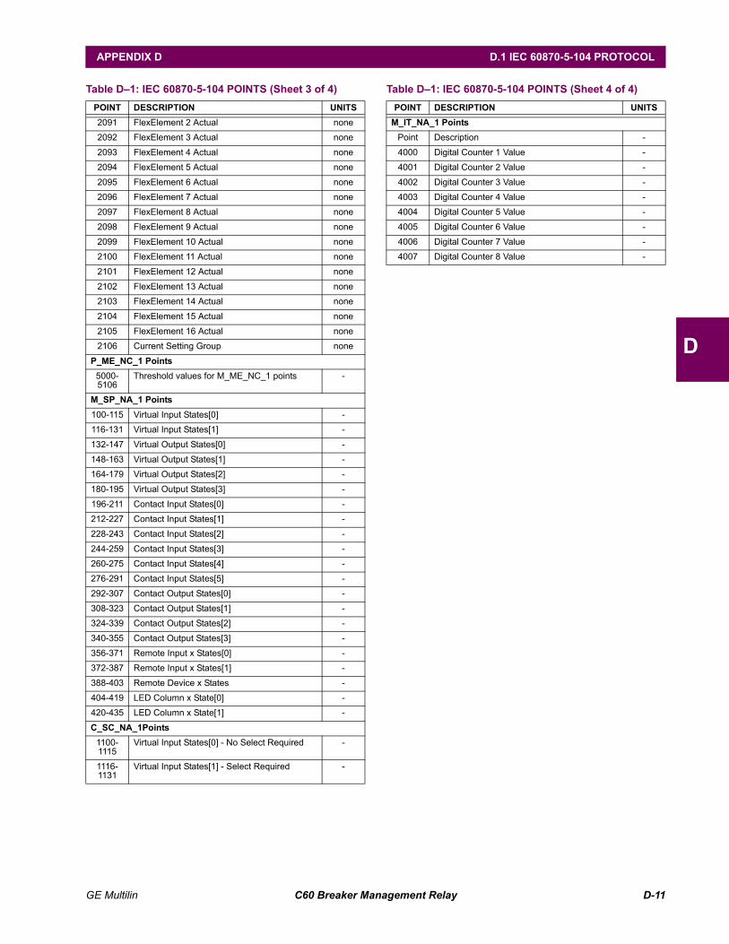
GE Multilin C60 Breaker Management Relay D-11
APPENDIX D D.1 IEC 60870-5-104 PROTOCOL
D
2091 FlexElement 2 Actual none
2092 FlexElement 3 Actual none
2093 FlexElement 4 Actual none
2094 FlexElement 5 Actual none
2095 FlexElement 6 Actual none
2096 FlexElement 7 Actual none
2097 FlexElement 8 Actual none
2098 FlexElement 9 Actual none
2099 FlexElement 10 Actual none
2100 FlexElement 11 Actual none
2101 FlexElement 12 Actual none
2102 FlexElement 13 Actual none
2103 FlexElement 14 Actual none
2104 FlexElement 15 Actual none
2105 FlexElement 16 Actual none
2106 Current Setting Group none
P_ME_NC_1 Points5000-5106
Threshold values for M_ME_NC_1 points -
M_SP_NA_1 Points100-115 Virtual Input States[0] -
116-131 Virtual Input States[1] -
132-147 Virtual Output States[0] -
148-163 Virtual Output States[1] -
164-179 Virtual Output States[2] -
180-195 Virtual Output States[3] -
196-211 Contact Input States[0] -
212-227 Contact Input States[1] -
228-243 Contact Input States[2] -
244-259 Contact Input States[3] -
260-275 Contact Input States[4] -
276-291 Contact Input States[5] -
292-307 Contact Output States[0] -
308-323 Contact Output States[1] -
324-339 Contact Output States[2] -
340-355 Contact Output States[3] -
356-371 Remote Input x States[0] -
372-387 Remote Input x States[1] -
388-403 Remote Device x States -
404-419 LED Column x State[0] -
420-435 LED Column x State[1] -
C_SC_NA_1Points1100-1115
Virtual Input States[0] - No Select Required -
1116-1131
Virtual Input States[1] - Select Required -
Table D1: IEC 60870-5-104 POINTS (Sheet 3 of 4)POINT DESCRIPTION UNITS
M_IT_NA_1 PointsPoint Description -
4000 Digital Counter 1 Value -
4001 Digital Counter 2 Value -
4002 Digital Counter 3 Value -
4003 Digital Counter 4 Value -
4004 Digital Counter 5 Value -
4005 Digital Counter 6 Value -
4006 Digital Counter 7 Value -
4007 Digital Counter 8 Value -
Table D1: IEC 60870-5-104 POINTS (Sheet 4 of 4)POINT DESCRIPTION UNITS

D-12 C60 Breaker Management Relay GE Multilin
D.1 IEC 60870-5-104 PROTOCOL APPENDIX D
D
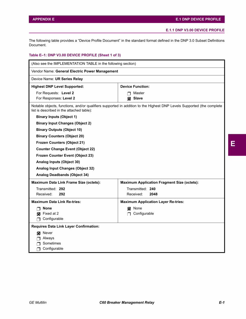
GE Multilin C60 Breaker Management Relay E-1
APPENDIX E E.1 DNP DEVICE PROFILE
E
APPENDIX E DNPE.1 DNP DEVICE PROFILE E.1.1 DNP V3.00 DEVICE PROFILE
The following table provides a Device Profile Document in the standard format defined in the DNP 3.0 Subset DefinitionsDocument.
Table E1: DNP V3.00 DEVICE PROFILE (Sheet 1 of 3)
(Also see the IMPLEMENTATION TABLE in the following section)
Vendor Name: General Electric Power Management
Device Name: UR Series Relay
Highest DNP Level Supported:
For Requests: Level 2For Responses: Level 2
Device Function:
MasterSlave
Notable objects, functions, and/or qualifiers supported in addition to the Highest DNP Levels Supported (the completelist is described in the attached table):
Binary Inputs (Object 1)
Binary Input Changes (Object 2)
Binary Outputs (Object 10)
Binary Counters (Object 20)
Frozen Counters (Object 21)
Counter Change Event (Object 22)
Frozen Counter Event (Object 23)
Analog Inputs (Object 30)
Analog Input Changes (Object 32)
Analog Deadbands (Object 34)
Maximum Data Link Frame Size (octets):
Transmitted: 292Received: 292
Maximum Application Fragment Size (octets):
Transmitted: 240Received: 2048
Maximum Data Link Re-tries:
NoneFixed at 2Configurable
Maximum Application Layer Re-tries:
NoneConfigurable
Requires Data Link Layer Confirmation:
NeverAlwaysSometimesConfigurable
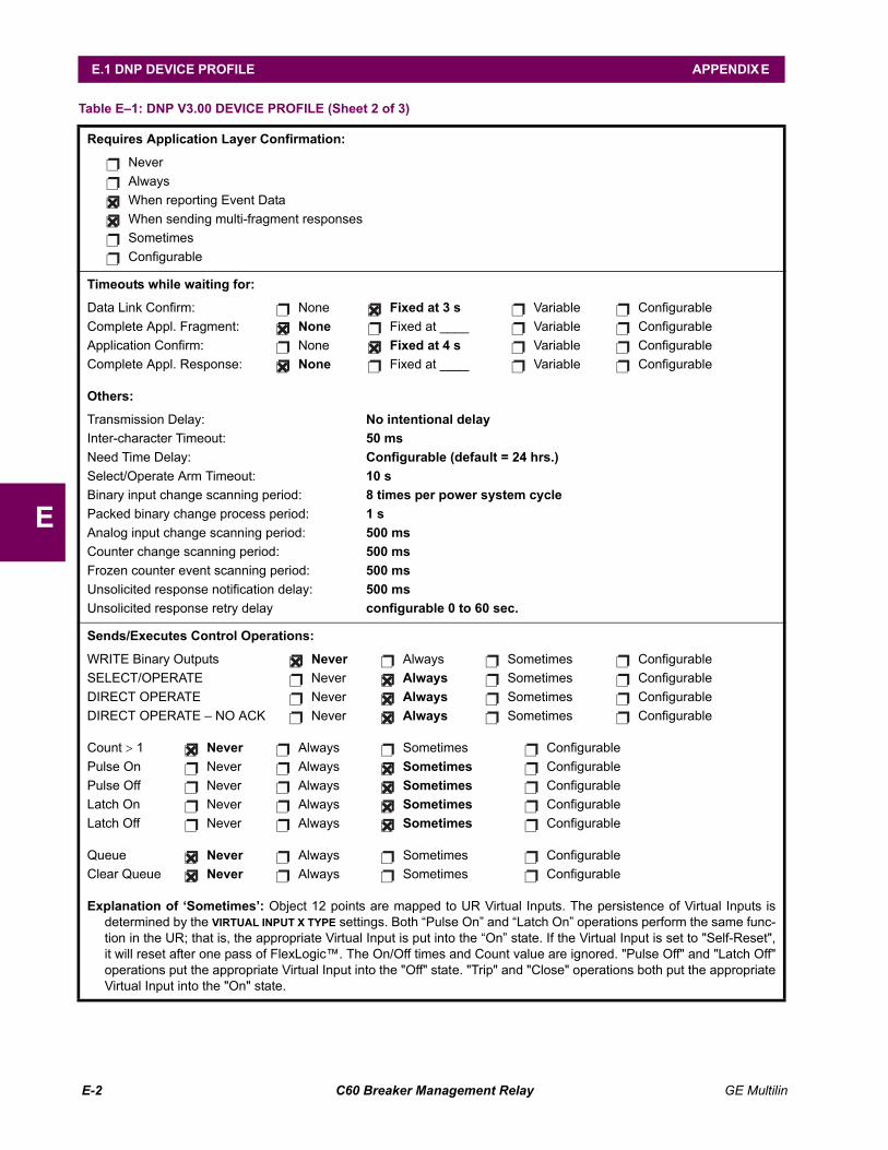
E-2 C60 Breaker Management Relay GE Multilin
E.1 DNP DEVICE PROFILE APPENDIX E
E
Requires Application Layer Confirmation:
NeverAlwaysWhen reporting Event DataWhen sending multi-fragment responsesSometimesConfigurable
Timeouts while waiting for:
Data Link Confirm: None Fixed at 3 s Variable ConfigurableComplete Appl. Fragment: None Fixed at ____ Variable ConfigurableApplication Confirm: None Fixed at 4 s Variable ConfigurableComplete Appl. Response: None Fixed at ____ Variable Configurable
Others:
Transmission Delay: No intentional delayInter-character Timeout: 50 msNeed Time Delay: Configurable (default = 24 hrs.)Select/Operate Arm Timeout: 10 sBinary input change scanning period: 8 times per power system cyclePacked binary change process period: 1 sAnalog input change scanning period: 500 msCounter change scanning period: 500 msFrozen counter event scanning period: 500 msUnsolicited response notification delay: 500 msUnsolicited response retry delay configurable 0 to 60 sec.
Sends/Executes Control Operations:
WRITE Binary Outputs Never Always Sometimes ConfigurableSELECT/OPERATE Never Always Sometimes ConfigurableDIRECT OPERATE Never Always Sometimes ConfigurableDIRECT OPERATE NO ACK Never Always Sometimes Configurable
Count > 1 Never Always Sometimes ConfigurablePulse On Never Always Sometimes ConfigurablePulse Off Never Always Sometimes ConfigurableLatch On Never Always Sometimes ConfigurableLatch Off Never Always Sometimes Configurable
Queue Never Always Sometimes ConfigurableClear Queue Never Always Sometimes Configurable
Explanation of Sometimes: Object 12 points are mapped to UR Virtual Inputs. The persistence of Virtual Inputs isdetermined by the VIRTUAL INPUT X TYPE settings. Both Pulse On and Latch On operations perform the same func-tion in the UR; that is, the appropriate Virtual Input is put into the On state. If the Virtual Input is set to "Self-Reset",it will reset after one pass of FlexLogic. The On/Off times and Count value are ignored. "Pulse Off" and "Latch Off"operations put the appropriate Virtual Input into the "Off" state. "Trip" and "Close" operations both put the appropriateVirtual Input into the "On" state.
Table E1: DNP V3.00 DEVICE PROFILE (Sheet 2 of 3)
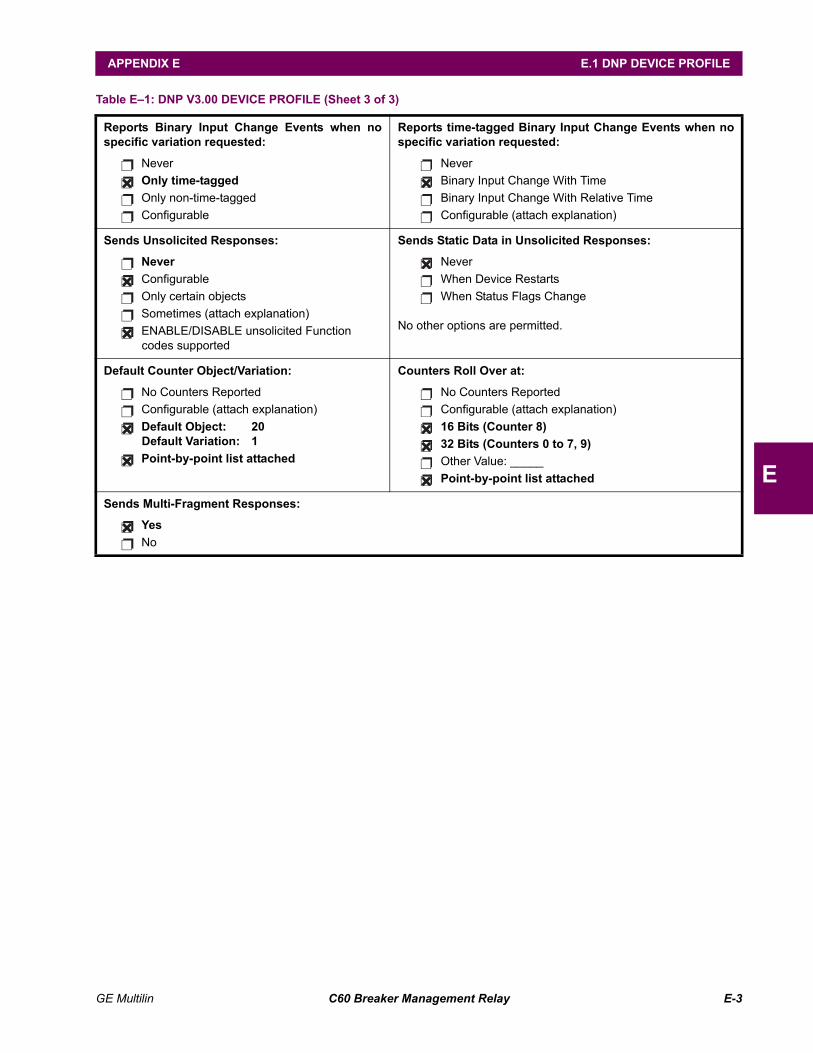
GE Multilin C60 Breaker Management Relay E-3
APPENDIX E E.1 DNP DEVICE PROFILE
E
Reports Binary Input Change Events when nospecific variation requested:
NeverOnly time-tagged Only non-time-taggedConfigurable
Reports time-tagged Binary Input Change Events when nospecific variation requested:
NeverBinary Input Change With TimeBinary Input Change With Relative TimeConfigurable (attach explanation)
Sends Unsolicited Responses:
Never ConfigurableOnly certain objects Sometimes (attach explanation)ENABLE/DISABLE unsolicited Function codes supported
Sends Static Data in Unsolicited Responses:
NeverWhen Device RestartsWhen Status Flags Change
No other options are permitted.
Default Counter Object/Variation:
No Counters ReportedConfigurable (attach explanation)Default Object: 20Default Variation: 1Point-by-point list attached
Counters Roll Over at:
No Counters ReportedConfigurable (attach explanation)16 Bits (Counter 8)32 Bits (Counters 0 to 7, 9)Other Value: _____Point-by-point list attached
Sends Multi-Fragment Responses:
YesNo
Table E1: DNP V3.00 DEVICE PROFILE (Sheet 3 of 3)
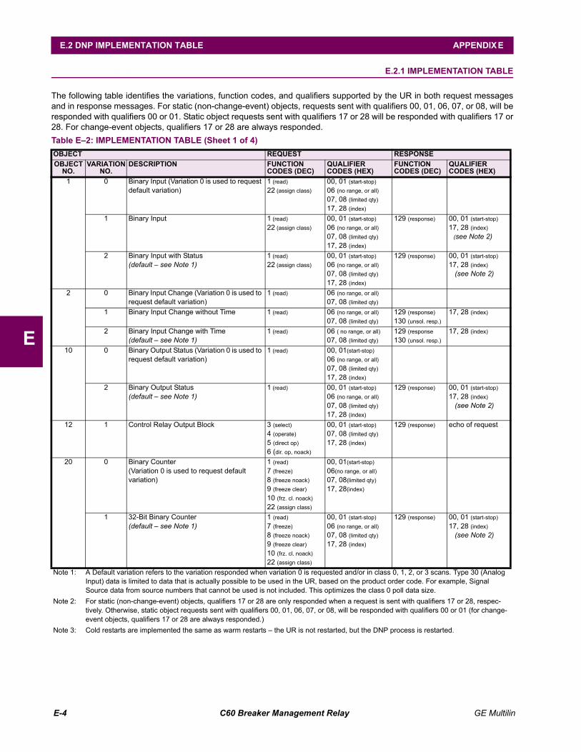
E-4 C60 Breaker Management Relay GE Multilin
E.2 DNP IMPLEMENTATION TABLE APPENDIX E
E
E.2 DNP IMPLEMENTATION TABLE E.2.1 IMPLEMENTATION TABLE
The following table identifies the variations, function codes, and qualifiers supported by the UR in both request messagesand in response messages. For static (non-change-event) objects, requests sent with qualifiers 00, 01, 06, 07, or 08, will beresponded with qualifiers 00 or 01. Static object requests sent with qualifiers 17 or 28 will be responded with qualifiers 17 or28. For change-event objects, qualifiers 17 or 28 are always responded.Table E2: IMPLEMENTATION TABLE (Sheet 1 of 4)OBJECT REQUEST RESPONSEOBJECT
NO.VARIATION
NO.DESCRIPTION FUNCTION
CODES (DEC)QUALIFIER CODES (HEX)
FUNCTION CODES (DEC)
QUALIFIER CODES (HEX)
1 0 Binary Input (Variation 0 is used to request default variation)
1 (read)22 (assign class)
00, 01 (start-stop)06 (no range, or all)07, 08 (limited qty)17, 28 (index)
1 Binary Input 1 (read)22 (assign class)
00, 01 (start-stop)06 (no range, or all)07, 08 (limited qty)17, 28 (index)
129 (response) 00, 01 (start-stop)17, 28 (index)
(see Note 2)
2 Binary Input with Status(default see Note 1)
1 (read)22 (assign class)
00, 01 (start-stop)06 (no range, or all)07, 08 (limited qty)17, 28 (index)
129 (response) 00, 01 (start-stop)17, 28 (index)
(see Note 2)
2 0 Binary Input Change (Variation 0 is used to request default variation)
1 (read) 06 (no range, or all)07, 08 (limited qty)
1 Binary Input Change without Time 1 (read) 06 (no range, or all)07, 08 (limited qty)
129 (response)130 (unsol. resp.)
17, 28 (index)
2 Binary Input Change with Time(default see Note 1)
1 (read) 06 ( no range, or all)07, 08 (limited qty)
129 (response130 (unsol. resp.)
17, 28 (index)
10 0 Binary Output Status (Variation 0 is used to request default variation)
1 (read) 00, 01(start-stop)06 (no range, or all)07, 08 (limited qty)17, 28 (index)
2 Binary Output Status(default see Note 1)
1 (read) 00, 01 (start-stop)06 (no range, or all)07, 08 (limited qty)17, 28 (index)
129 (response) 00, 01 (start-stop)17, 28 (index)
(see Note 2)
12 1 Control Relay Output Block 3 (select)4 (operate)5 (direct op)6 (dir. op, noack)
00, 01 (start-stop)07, 08 (limited qty)17, 28 (index)
129 (response) echo of request
20 0 Binary Counter(Variation 0 is used to request default variation)
1 (read)7 (freeze)8 (freeze noack)9 (freeze clear)10 (frz. cl. noack)22 (assign class)
00, 01(start-stop)06(no range, or all)07, 08(limited qty)17, 28(index)
1 32-Bit Binary Counter(default see Note 1)
1 (read)7 (freeze)8 (freeze noack)9 (freeze clear)10 (frz. cl. noack)22 (assign class)
00, 01 (start-stop)06 (no range, or all)07, 08 (limited qty)17, 28 (index)
129 (response) 00, 01 (start-stop)17, 28 (index)
(see Note 2)
Note 1: A Default variation refers to the variation responded when variation 0 is requested and/or in class 0, 1, 2, or 3 scans. Type 30 (Analog Input) data is limited to data that is actually possible to be used in the UR, based on the product order code. For example, Signal Source data from source numbers that cannot be used is not included. This optimizes the class 0 poll data size.
Note 2: For static (non-change-event) objects, qualifiers 17 or 28 are only responded when a request is sent with qualifiers 17 or 28, respec-tively. Otherwise, static object requests sent with qualifiers 00, 01, 06, 07, or 08, will be responded with qualifiers 00 or 01 (for change-event objects, qualifiers 17 or 28 are always responded.)
Note 3: Cold restarts are implemented the same as warm restarts the UR is not restarted, but the DNP process is restarted.
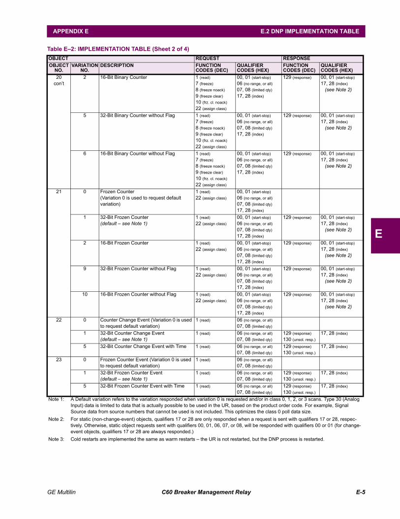
GE Multilin C60 Breaker Management Relay E-5
APPENDIX E E.2 DNP IMPLEMENTATION TABLE
E
20cont
2 16-Bit Binary Counter 1 (read)7 (freeze)8 (freeze noack)9 (freeze clear)10 (frz. cl. noack)22 (assign class)
00, 01 (start-stop)06 (no range, or all)07, 08 (limited qty)17, 28 (index)
129 (response) 00, 01 (start-stop)17, 28 (index)
(see Note 2)
5 32-Bit Binary Counter without Flag 1 (read)7 (freeze)8 (freeze noack)9 (freeze clear)10 (frz. cl. noack)22 (assign class)
00, 01 (start-stop)06 (no range, or all)07, 08 (limited qty)17, 28 (index)
129 (response) 00, 01 (start-stop)17, 28 (index)
(see Note 2)
6 16-Bit Binary Counter without Flag 1 (read)7 (freeze)8 (freeze noack)9 (freeze clear)10 (frz. cl. noack)22 (assign class)
00, 01 (start-stop)06 (no range, or all)07, 08 (limited qty)17, 28 (index)
129 (response) 00, 01 (start-stop)17, 28 (index)
(see Note 2)
21 0 Frozen Counter(Variation 0 is used to request default variation)
1 (read)22 (assign class)
00, 01 (start-stop)06 (no range, or all)07, 08 (limited qty)17, 28 (index)
1 32-Bit Frozen Counter(default see Note 1)
1 (read)22 (assign class)
00, 01 (start-stop)06 (no range, or all)07, 08 (limited qty)17, 28 (index)
129 (response) 00, 01 (start-stop)17, 28 (index)
(see Note 2)
2 16-Bit Frozen Counter 1 (read)22 (assign class)
00, 01 (start-stop)06 (no range, or all)07, 08 (limited qty)17, 28 (index)
129 (response) 00, 01 (start-stop)17, 28 (index)
(see Note 2)
9 32-Bit Frozen Counter without Flag 1 (read)22 (assign class)
00, 01 (start-stop)06 (no range, or all)07, 08 (limited qty)17, 28 (index)
129 (response) 00, 01 (start-stop)17, 28 (index)
(see Note 2)
10 16-Bit Frozen Counter without Flag 1 (read)22 (assign class)
00, 01 (start-stop)06 (no range, or all)07, 08 (limited qty)17, 28 (index)
129 (response) 00, 01 (start-stop)17, 28 (index)
(see Note 2)
22 0 Counter Change Event (Variation 0 is used to request default variation)
1 (read) 06 (no range, or all)07, 08 (limited qty)
1 32-Bit Counter Change Event(default see Note 1)
1 (read) 06 (no range, or all)07, 08 (limited qty)
129 (response)130 (unsol. resp.)
17, 28 (index)
5 32-Bit Counter Change Event with Time 1 (read) 06 (no range, or all)07, 08 (limited qty)
129 (response)130 (unsol. resp.)
17, 28 (index)
23 0 Frozen Counter Event (Variation 0 is used to request default variation)
1 (read) 06 (no range, or all)07, 08 (limited qty)
1 32-Bit Frozen Counter Event(default see Note 1)
1 (read) 06 (no range, or all)07, 08 (limited qty)
129 (response)130 (unsol. resp.)
17, 28 (index)
5 32-Bit Frozen Counter Event with Time 1 (read) 06 (no range, or all)07, 08 (limited qty)
129 (response)130 (unsol. resp.)
17, 28 (index)
Table E2: IMPLEMENTATION TABLE (Sheet 2 of 4)OBJECT REQUEST RESPONSEOBJECT
NO.VARIATION
NO.DESCRIPTION FUNCTION
CODES (DEC)QUALIFIER CODES (HEX)
FUNCTION CODES (DEC)
QUALIFIER CODES (HEX)
Note 1: A Default variation refers to the variation responded when variation 0 is requested and/or in class 0, 1, 2, or 3 scans. Type 30 (Analog Input) data is limited to data that is actually possible to be used in the UR, based on the product order code. For example, Signal Source data from source numbers that cannot be used is not included. This optimizes the class 0 poll data size.
Note 2: For static (non-change-event) objects, qualifiers 17 or 28 are only responded when a request is sent with qualifiers 17 or 28, respec-tively. Otherwise, static object requests sent with qualifiers 00, 01, 06, 07, or 08, will be responded with qualifiers 00 or 01 (for change-event objects, qualifiers 17 or 28 are always responded.)
Note 3: Cold restarts are implemented the same as warm restarts the UR is not restarted, but the DNP process is restarted.
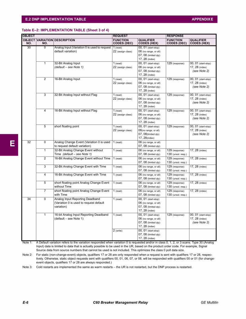
E-6 C60 Breaker Management Relay GE Multilin
E.2 DNP IMPLEMENTATION TABLE APPENDIX E
E
30 0 Analog Input (Variation 0 is used to request default variation)
1 (read)22 (assign class)
00, 01 (start-stop)06 (no range, or all)07, 08 (limited qty)17, 28 (index)
1 32-Bit Analog Input(default see Note 1)
1 (read)22 (assign class)
00, 01 (start-stop)06 (no range, or all)07, 08 (limited qty)17, 28 (index)
129 (response) 00, 01 (start-stop)17, 28 (index)
(see Note 2)
2 16-Bit Analog Input 1 (read)22 (assign class)
00, 01 (start-stop)06 (no range, or all)07, 08 (limited qty)17, 28 (index)
129 (response) 00, 01 (start-stop)17, 28 (index)
(see Note 2)
3 32-Bit Analog Input without Flag 1 (read)22 (assign class)
00, 01 (start-stop)06 (no range, or all)07, 08 (limited qty)17, 28 (index)
129 (response) 00, 01 (start-stop)17, 28 (index)
(see Note 2)
4 16-Bit Analog Input without Flag 1 (read)22 (assign class)
00, 01 (start-stop)06 (no range, or all)07, 08 (limited qty)17, 28 (index)
129 (response) 00, 01 (start-stop)17, 28 (index)
(see Note 2)
5 short floating point 1 (read)22 (assign class)
00, 01 (start-stop)06(no range, or all)07, 08(limited qty)17, 28(index)
129 (response) 00, 01 (start-stop)17, 28 (index)
(see Note 2)
32 0 Analog Change Event (Variation 0 is used to request default variation)
1 (read) 06 (no range, or all)07, 08 (limited qty)
1 32-Bit Analog Change Event without Time (default see Note 1)
1 (read) 06 (no range, or all)07, 08 (limited qty)
129 (response)130 (unsol. resp.)
17, 28 (index)
2 16-Bit Analog Change Event without Time 1 (read) 06 (no range, or all)07, 08 (limited qty)
129 (response)130 (unsol. resp.)
17, 28 (index)
3 32-Bit Analog Change Event with Time 1 (read) 06 (no range, or all)07, 08 (limited qty)
129 (response)130 (unsol. resp.)
17, 28 (index)
4 16-Bit Analog Change Event with Time 1 (read) 06 (no range, or all)07, 08 (limited qty)
129 (response)130 (unsol. resp.)
17, 28 (index)
5 short floating point Analog Change Event without Time
1 (read) 06 (no range, or all)07, 08 (limited qty)
129 (response)130 (unsol. resp.)
17, 28 (index)
7 short floating point Analog Change Event with Time
1 (read) 06 (no range, or all)07, 08 (limited qty)
129 (response)130 (unsol. resp.)
17, 28 (index)
34 0 Analog Input Reporting Deadband(Variation 0 is used to request default variation)
1 (read) 00, 01 (start-stop)06 (no range, or all)07, 08 (limited qty)17, 28 (index)
1 16-bit Analog Input Reporting Deadband(default see Note 1)
1 (read) 00, 01 (start-stop)06 (no range, or all)07, 08 (limited qty)17, 28 (index)
129 (response) 00, 01 (start-stop)17, 28 (index)
(see Note 2)
2 (write) 00, 01 (start-stop)07, 08 (limited qty)17, 28 (index)
Table E2: IMPLEMENTATION TABLE (Sheet 3 of 4)OBJECT REQUEST RESPONSEOBJECT
NO.VARIATION
NO.DESCRIPTION FUNCTION
CODES (DEC)QUALIFIER CODES (HEX)
FUNCTION CODES (DEC)
QUALIFIER CODES (HEX)
Note 1: A Default variation refers to the variation responded when variation 0 is requested and/or in class 0, 1, 2, or 3 scans. Type 30 (Analog Input) data is limited to data that is actually possible to be used in the UR, based on the product order code. For example, Signal Source data from source numbers that cannot be used is not included. This optimizes the class 0 poll data size.
Note 2: For static (non-change-event) objects, qualifiers 17 or 28 are only responded when a request is sent with qualifiers 17 or 28, respec-tively. Otherwise, static object requests sent with qualifiers 00, 01, 06, 07, or 08, will be responded with qualifiers 00 or 01 (for change-event objects, qualifiers 17 or 28 are always responded.)
Note 3: Cold restarts are implemented the same as warm restarts the UR is not restarted, but the DNP process is restarted.
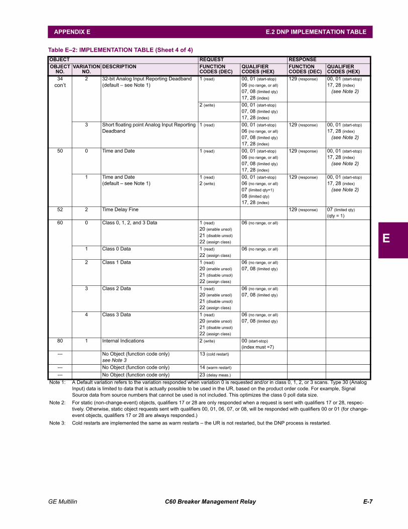
GE Multilin C60 Breaker Management Relay E-7
APPENDIX E E.2 DNP IMPLEMENTATION TABLE
E
34cont
2 32-bit Analog Input Reporting Deadband(default see Note 1)
1 (read) 00, 01 (start-stop)06 (no range, or all)07, 08 (limited qty)17, 28 (index)
129 (response) 00, 01 (start-stop)17, 28 (index)
(see Note 2)
2 (write) 00, 01 (start-stop)07, 08 (limited qty)17, 28 (index)
3 Short floating point Analog Input Reporting Deadband
1 (read) 00, 01 (start-stop)06 (no range, or all)07, 08 (limited qty)17, 28 (index)
129 (response) 00, 01 (start-stop)17, 28 (index)
(see Note 2)
50 0 Time and Date 1 (read) 00, 01 (start-stop)06 (no range, or all)07, 08 (limited qty)17, 28 (index)
129 (response) 00, 01 (start-stop)17, 28 (index)
(see Note 2)
1 Time and Date(default see Note 1)
1 (read)2 (write)
00, 01 (start-stop)06 (no range, or all)07 (limited qty=1)08 (limited qty)17, 28 (index)
129 (response) 00, 01 (start-stop)17, 28 (index)
(see Note 2)
52 2 Time Delay Fine 129 (response) 07 (limited qty)(qty = 1)
60 0 Class 0, 1, 2, and 3 Data 1 (read)20 (enable unsol)21 (disable unsol)22 (assign class)
06 (no range, or all)
1 Class 0 Data 1 (read)22 (assign class)
06 (no range, or all)
2 Class 1 Data 1 (read)20 (enable unsol)21 (disable unsol)22 (assign class)
06 (no range, or all)07, 08 (limited qty)
3 Class 2 Data 1 (read)20 (enable unsol)21 (disable unsol)22 (assign class)
06 (no range, or all)07, 08 (limited qty)
4 Class 3 Data 1 (read)20 (enable unsol)21 (disable unsol)22 (assign class)
06 (no range, or all)07, 08 (limited qty)
80 1 Internal Indications 2 (write) 00 (start-stop)(index must =7)
--- No Object (function code only)see Note 3
13 (cold restart)
--- No Object (function code only) 14 (warm restart)
--- No Object (function code only) 23 (delay meas.)
Table E2: IMPLEMENTATION TABLE (Sheet 4 of 4)OBJECT REQUEST RESPONSEOBJECT
NO.VARIATION
NO.DESCRIPTION FUNCTION
CODES (DEC)QUALIFIER CODES (HEX)
FUNCTION CODES (DEC)
QUALIFIER CODES (HEX)
Note 1: A Default variation refers to the variation responded when variation 0 is requested and/or in class 0, 1, 2, or 3 scans. Type 30 (Analog Input) data is limited to data that is actually possible to be used in the UR, based on the product order code. For example, Signal Source data from source numbers that cannot be used is not included. This optimizes the class 0 poll data size.
Note 2: For static (non-change-event) objects, qualifiers 17 or 28 are only responded when a request is sent with qualifiers 17 or 28, respec-tively. Otherwise, static object requests sent with qualifiers 00, 01, 06, 07, or 08, will be responded with qualifiers 00 or 01 (for change-event objects, qualifiers 17 or 28 are always responded.)
Note 3: Cold restarts are implemented the same as warm restarts the UR is not restarted, but the DNP process is restarted.
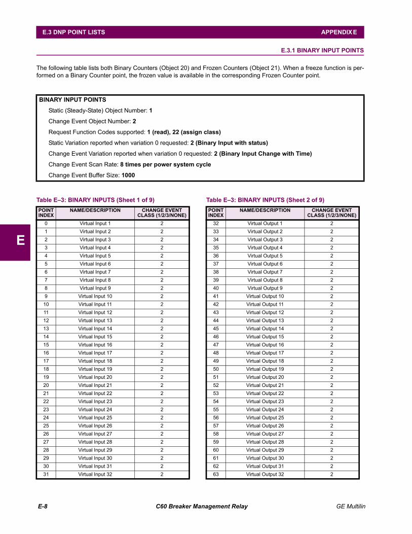
E-8 C60 Breaker Management Relay GE Multilin
E.3 DNP POINT LISTS APPENDIX E
E
E.3 DNP POINT LISTS E.3.1 BINARY INPUT POINTS
The following table lists both Binary Counters (Object 20) and Frozen Counters (Object 21). When a freeze function is per-formed on a Binary Counter point, the frozen value is available in the corresponding Frozen Counter point.
BINARY INPUT POINTS
Static (Steady-State) Object Number: 1
Change Event Object Number: 2
Request Function Codes supported: 1 (read), 22 (assign class)
Static Variation reported when variation 0 requested: 2 (Binary Input with status)
Change Event Variation reported when variation 0 requested: 2 (Binary Input Change with Time)
Change Event Scan Rate: 8 times per power system cycle
Change Event Buffer Size: 1000
Table E3: BINARY INPUTS (Sheet 1 of 9)POINTINDEX
NAME/DESCRIPTION CHANGE EVENT CLASS (1/2/3/NONE)
0 Virtual Input 1 21 Virtual Input 2 22 Virtual Input 3 23 Virtual Input 4 24 Virtual Input 5 25 Virtual Input 6 26 Virtual Input 7 27 Virtual Input 8 28 Virtual Input 9 29 Virtual Input 10 2
10 Virtual Input 11 211 Virtual Input 12 212 Virtual Input 13 213 Virtual Input 14 214 Virtual Input 15 215 Virtual Input 16 216 Virtual Input 17 217 Virtual Input 18 218 Virtual Input 19 219 Virtual Input 20 220 Virtual Input 21 221 Virtual Input 22 222 Virtual Input 23 223 Virtual Input 24 224 Virtual Input 25 225 Virtual Input 26 226 Virtual Input 27 227 Virtual Input 28 228 Virtual Input 29 229 Virtual Input 30 230 Virtual Input 31 231 Virtual Input 32 2
32 Virtual Output 1 233 Virtual Output 2 234 Virtual Output 3 235 Virtual Output 4 236 Virtual Output 5 237 Virtual Output 6 238 Virtual Output 7 239 Virtual Output 8 240 Virtual Output 9 241 Virtual Output 10 242 Virtual Output 11 243 Virtual Output 12 244 Virtual Output 13 245 Virtual Output 14 246 Virtual Output 15 247 Virtual Output 16 248 Virtual Output 17 249 Virtual Output 18 250 Virtual Output 19 251 Virtual Output 20 252 Virtual Output 21 253 Virtual Output 22 254 Virtual Output 23 255 Virtual Output 24 256 Virtual Output 25 257 Virtual Output 26 258 Virtual Output 27 259 Virtual Output 28 260 Virtual Output 29 261 Virtual Output 30 262 Virtual Output 31 263 Virtual Output 32 2
Table E3: BINARY INPUTS (Sheet 2 of 9)POINTINDEX
NAME/DESCRIPTION CHANGE EVENT CLASS (1/2/3/NONE)
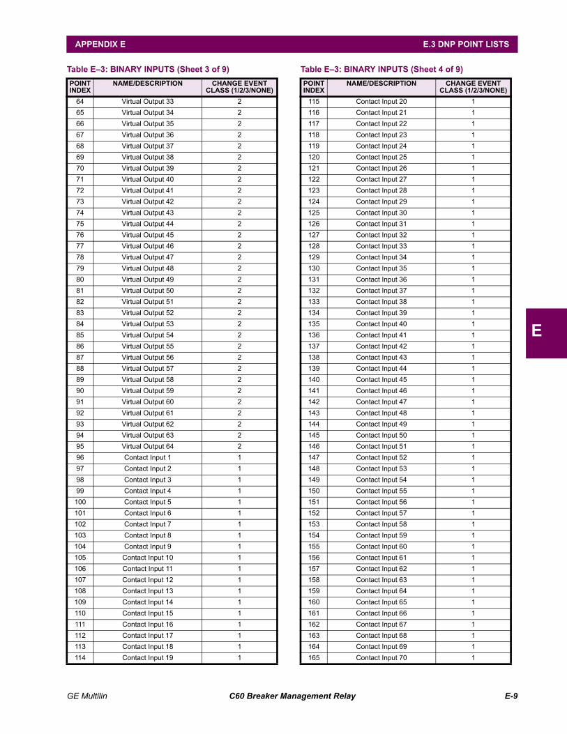
GE Multilin C60 Breaker Management Relay E-9
APPENDIX E E.3 DNP POINT LISTS
E
64 Virtual Output 33 265 Virtual Output 34 266 Virtual Output 35 267 Virtual Output 36 268 Virtual Output 37 269 Virtual Output 38 270 Virtual Output 39 271 Virtual Output 40 272 Virtual Output 41 273 Virtual Output 42 274 Virtual Output 43 275 Virtual Output 44 276 Virtual Output 45 277 Virtual Output 46 278 Virtual Output 47 279 Virtual Output 48 280 Virtual Output 49 281 Virtual Output 50 282 Virtual Output 51 283 Virtual Output 52 284 Virtual Output 53 285 Virtual Output 54 286 Virtual Output 55 287 Virtual Output 56 288 Virtual Output 57 289 Virtual Output 58 290 Virtual Output 59 291 Virtual Output 60 292 Virtual Output 61 293 Virtual Output 62 294 Virtual Output 63 295 Virtual Output 64 296 Contact Input 1 197 Contact Input 2 198 Contact Input 3 199 Contact Input 4 1100 Contact Input 5 1101 Contact Input 6 1102 Contact Input 7 1103 Contact Input 8 1104 Contact Input 9 1105 Contact Input 10 1106 Contact Input 11 1107 Contact Input 12 1108 Contact Input 13 1109 Contact Input 14 1110 Contact Input 15 1111 Contact Input 16 1112 Contact Input 17 1113 Contact Input 18 1114 Contact Input 19 1
Table E3: BINARY INPUTS (Sheet 3 of 9)POINTINDEX
NAME/DESCRIPTION CHANGE EVENT CLASS (1/2/3/NONE)
115 Contact Input 20 1116 Contact Input 21 1117 Contact Input 22 1118 Contact Input 23 1119 Contact Input 24 1120 Contact Input 25 1121 Contact Input 26 1122 Contact Input 27 1123 Contact Input 28 1124 Contact Input 29 1125 Contact Input 30 1126 Contact Input 31 1127 Contact Input 32 1128 Contact Input 33 1129 Contact Input 34 1130 Contact Input 35 1131 Contact Input 36 1132 Contact Input 37 1133 Contact Input 38 1134 Contact Input 39 1135 Contact Input 40 1136 Contact Input 41 1137 Contact Input 42 1138 Contact Input 43 1139 Contact Input 44 1140 Contact Input 45 1141 Contact Input 46 1142 Contact Input 47 1143 Contact Input 48 1144 Contact Input 49 1145 Contact Input 50 1146 Contact Input 51 1147 Contact Input 52 1148 Contact Input 53 1149 Contact Input 54 1150 Contact Input 55 1151 Contact Input 56 1152 Contact Input 57 1153 Contact Input 58 1154 Contact Input 59 1155 Contact Input 60 1156 Contact Input 61 1157 Contact Input 62 1158 Contact Input 63 1159 Contact Input 64 1160 Contact Input 65 1161 Contact Input 66 1162 Contact Input 67 1163 Contact Input 68 1164 Contact Input 69 1165 Contact Input 70 1
Table E3: BINARY INPUTS (Sheet 4 of 9)POINTINDEX
NAME/DESCRIPTION CHANGE EVENT CLASS (1/2/3/NONE)
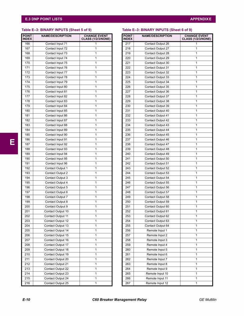
E-10 C60 Breaker Management Relay GE Multilin
E.3 DNP POINT LISTS APPENDIX E
E
166 Contact Input 71 1167 Contact Input 72 1168 Contact Input 73 1169 Contact Input 74 1170 Contact Input 75 1171 Contact Input 76 1172 Contact Input 77 1173 Contact Input 78 1174 Contact Input 79 1175 Contact Input 80 1176 Contact Input 81 1177 Contact Input 82 1178 Contact Input 83 1179 Contact Input 84 1180 Contact Input 85 1181 Contact Input 86 1182 Contact Input 87 1183 Contact Input 88 1184 Contact Input 89 1185 Contact Input 90 1186 Contact Input 91 1187 Contact Input 92 1188 Contact Input 93 1189 Contact Input 94 1190 Contact Input 95 1191 Contact Input 96 1192 Contact Output 1 1193 Contact Output 2 1194 Contact Output 3 1195 Contact Output 4 1196 Contact Output 5 1197 Contact Output 6 1198 Contact Output 7 1199 Contact Output 8 1200 Contact Output 9 1201 Contact Output 10 1202 Contact Output 11 1203 Contact Output 12 1204 Contact Output 13 1205 Contact Output 14 1206 Contact Output 15 1207 Contact Output 16 1208 Contact Output 17 1209 Contact Output 18 1210 Contact Output 19 1211 Contact Output 20 1212 Contact Output 21 1213 Contact Output 22 1214 Contact Output 23 1215 Contact Output 24 1216 Contact Output 25 1
Table E3: BINARY INPUTS (Sheet 5 of 9)POINTINDEX
NAME/DESCRIPTION CHANGE EVENT CLASS (1/2/3/NONE)
217 Contact Output 26 1218 Contact Output 27 1219 Contact Output 28 1220 Contact Output 29 1221 Contact Output 30 1222 Contact Output 31 1223 Contact Output 32 1224 Contact Output 33 1225 Contact Output 34 1226 Contact Output 35 1227 Contact Output 36 1228 Contact Output 37 1229 Contact Output 38 1230 Contact Output 39 1231 Contact Output 40 1232 Contact Output 41 1233 Contact Output 42 1234 Contact Output 43 1235 Contact Output 44 1236 Contact Output 45 1237 Contact Output 46 1238 Contact Output 47 1239 Contact Output 48 1240 Contact Output 49 1241 Contact Output 50 1242 Contact Output 51 1243 Contact Output 52 1244 Contact Output 53 1245 Contact Output 54 1246 Contact Output 55 1247 Contact Output 56 1248 Contact Output 57 1249 Contact Output 58 1250 Contact Output 59 1251 Contact Output 60 1252 Contact Output 61 1253 Contact Output 62 1254 Contact Output 63 1255 Contact Output 64 1256 Remote Input 1 1257 Remote Input 2 1258 Remote Input 3 1259 Remote Input 4 1260 Remote Input 5 1261 Remote Input 6 1262 Remote Input 7 1263 Remote Input 8 1264 Remote Input 9 1265 Remote Input 10 1266 Remote Input 11 1267 Remote Input 12 1
Table E3: BINARY INPUTS (Sheet 6 of 9)POINTINDEX
NAME/DESCRIPTION CHANGE EVENT CLASS (1/2/3/NONE)
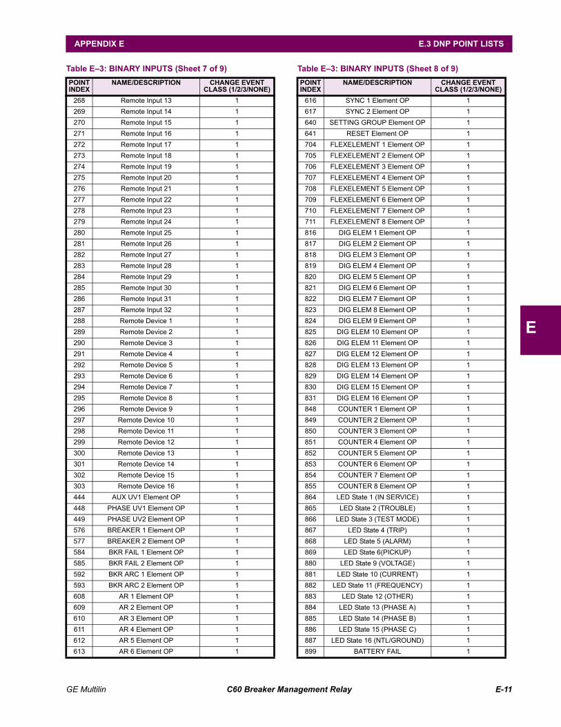
GE Multilin C60 Breaker Management Relay E-11
APPENDIX E E.3 DNP POINT LISTS
E
268 Remote Input 13 1269 Remote Input 14 1270 Remote Input 15 1271 Remote Input 16 1272 Remote Input 17 1273 Remote Input 18 1274 Remote Input 19 1275 Remote Input 20 1276 Remote Input 21 1277 Remote Input 22 1278 Remote Input 23 1279 Remote Input 24 1280 Remote Input 25 1281 Remote Input 26 1282 Remote Input 27 1283 Remote Input 28 1284 Remote Input 29 1285 Remote Input 30 1286 Remote Input 31 1287 Remote Input 32 1288 Remote Device 1 1289 Remote Device 2 1290 Remote Device 3 1291 Remote Device 4 1292 Remote Device 5 1293 Remote Device 6 1294 Remote Device 7 1295 Remote Device 8 1296 Remote Device 9 1297 Remote Device 10 1298 Remote Device 11 1299 Remote Device 12 1300 Remote Device 13 1301 Remote Device 14 1302 Remote Device 15 1303 Remote Device 16 1444 AUX UV1 Element OP 1448 PHASE UV1 Element OP 1449 PHASE UV2 Element OP 1576 BREAKER 1 Element OP 1577 BREAKER 2 Element OP 1584 BKR FAIL 1 Element OP 1585 BKR FAIL 2 Element OP 1592 BKR ARC 1 Element OP 1593 BKR ARC 2 Element OP 1608 AR 1 Element OP 1609 AR 2 Element OP 1610 AR 3 Element OP 1611 AR 4 Element OP 1612 AR 5 Element OP 1613 AR 6 Element OP 1
Table E3: BINARY INPUTS (Sheet 7 of 9)POINTINDEX
NAME/DESCRIPTION CHANGE EVENT CLASS (1/2/3/NONE)
616 SYNC 1 Element OP 1617 SYNC 2 Element OP 1640 SETTING GROUP Element OP 1641 RESET Element OP 1704 FLEXELEMENT 1 Element OP 1705 FLEXELEMENT 2 Element OP 1706 FLEXELEMENT 3 Element OP 1707 FLEXELEMENT 4 Element OP 1708 FLEXELEMENT 5 Element OP 1709 FLEXELEMENT 6 Element OP 1710 FLEXELEMENT 7 Element OP 1711 FLEXELEMENT 8 Element OP 1816 DIG ELEM 1 Element OP 1817 DIG ELEM 2 Element OP 1818 DIG ELEM 3 Element OP 1819 DIG ELEM 4 Element OP 1820 DIG ELEM 5 Element OP 1821 DIG ELEM 6 Element OP 1822 DIG ELEM 7 Element OP 1823 DIG ELEM 8 Element OP 1824 DIG ELEM 9 Element OP 1825 DIG ELEM 10 Element OP 1826 DIG ELEM 11 Element OP 1827 DIG ELEM 12 Element OP 1828 DIG ELEM 13 Element OP 1829 DIG ELEM 14 Element OP 1830 DIG ELEM 15 Element OP 1831 DIG ELEM 16 Element OP 1848 COUNTER 1 Element OP 1849 COUNTER 2 Element OP 1850 COUNTER 3 Element OP 1851 COUNTER 4 Element OP 1852 COUNTER 5 Element OP 1853 COUNTER 6 Element OP 1854 COUNTER 7 Element OP 1855 COUNTER 8 Element OP 1864 LED State 1 (IN SERVICE) 1865 LED State 2 (TROUBLE) 1866 LED State 3 (TEST MODE) 1867 LED State 4 (TRIP) 1868 LED State 5 (ALARM) 1869 LED State 6(PICKUP) 1880 LED State 9 (VOLTAGE) 1881 LED State 10 (CURRENT) 1882 LED State 11 (FREQUENCY) 1883 LED State 12 (OTHER) 1884 LED State 13 (PHASE A) 1885 LED State 14 (PHASE B) 1886 LED State 15 (PHASE C) 1887 LED State 16 (NTL/GROUND) 1899 BATTERY FAIL 1
Table E3: BINARY INPUTS (Sheet 8 of 9)POINTINDEX
NAME/DESCRIPTION CHANGE EVENT CLASS (1/2/3/NONE)
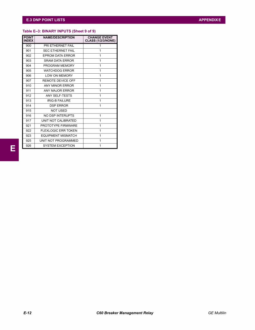
E-12 C60 Breaker Management Relay GE Multilin
E.3 DNP POINT LISTS APPENDIX E
E
900 PRI ETHERNET FAIL 1901 SEC ETHERNET FAIL 1902 EPROM DATA ERROR 1903 SRAM DATA ERROR 1904 PROGRAM MEMORY 1905 WATCHDOG ERROR 1906 LOW ON MEMORY 1907 REMOTE DEVICE OFF 1910 ANY MINOR ERROR 1911 ANY MAJOR ERROR 1912 ANY SELF-TESTS 1913 IRIG-B FAILURE 1914 DSP ERROR 1915 NOT USED916 NO DSP INTERUPTS 1917 UNIT NOT CALIBRATED 1921 PROTOTYPE FIRMWARE 1922 FLEXLOGIC ERR TOKEN 1923 EQUIPMENT MISMATCH 1925 UNIT NOT PROGRAMMED 1926 SYSTEM EXCEPTION 1
Table E3: BINARY INPUTS (Sheet 9 of 9)POINTINDEX
NAME/DESCRIPTION CHANGE EVENT CLASS (1/2/3/NONE)
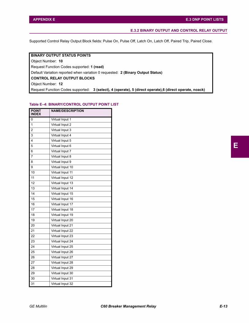
GE Multilin C60 Breaker Management Relay E-13
APPENDIX E E.3 DNP POINT LISTS
E
E.3.2 BINARY OUTPUT AND CONTROL RELAY OUTPUT
Supported Control Relay Output Block fields: Pulse On, Pulse Off, Latch On, Latch Off, Paired Trip, Paired Close.
BINARY OUTPUT STATUS POINTSObject Number: 10Request Function Codes supported: 1 (read)Default Variation reported when variation 0 requested: 2 (Binary Output Status)CONTROL RELAY OUTPUT BLOCKSObject Number: 12Request Function Codes supported: 3 (select), 4 (operate), 5 (direct operate),6 (direct operate, noack)
Table E4: BINARY/CONTROL OUTPUT POINT LISTPOINTINDEX
NAME/DESCRIPTION
0 Virtual Input 11 Virtual Input 22 Virtual Input 33 Virtual Input 44 Virtual Input 55 Virtual Input 66 Virtual Input 77 Virtual Input 88 Virtual Input 99 Virtual Input 1010 Virtual Input 1111 Virtual Input 1212 Virtual Input 1313 Virtual Input 1414 Virtual Input 1515 Virtual Input 1616 Virtual Input 1717 Virtual Input 1818 Virtual Input 1919 Virtual Input 2020 Virtual Input 2121 Virtual Input 2222 Virtual Input 2323 Virtual Input 2424 Virtual Input 2525 Virtual Input 2626 Virtual Input 2727 Virtual Input 2828 Virtual Input 2929 Virtual Input 3030 Virtual Input 3131 Virtual Input 32
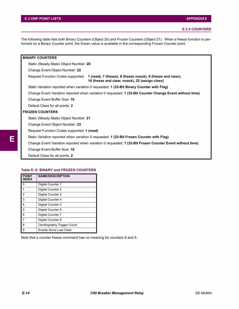
E-14 C60 Breaker Management Relay GE Multilin
E.3 DNP POINT LISTS APPENDIX E
E
E.3.3 COUNTERS
The following table lists both Binary Counters (Object 20) and Frozen Counters (Object 21). When a freeze function is per-formed on a Binary Counter point, the frozen value is available in the corresponding Frozen Counter point.
Note that a counter freeze command has no meaning for counters 8 and 9.
BINARY COUNTERS
Static (Steady-State) Object Number: 20
Change Event Object Number: 22
Request Function Codes supported: 1 (read), 7 (freeze), 8 (freeze noack), 9 (freeze and clear),10 (freeze and clear, noack), 22 (assign class)
Static Variation reported when variation 0 requested: 1 (32-Bit Binary Counter with Flag)
Change Event Variation reported when variation 0 requested: 1 (32-Bit Counter Change Event without time)
Change Event Buffer Size: 10
Default Class for all points: 2
FROZEN COUNTERS
Static (Steady-State) Object Number: 21
Change Event Object Number: 23
Request Function Codes supported: 1 (read)
Static Variation reported when variation 0 requested: 1 (32-Bit Frozen Counter with Flag)
Change Event Variation reported when variation 0 requested: 1 (32-Bit Frozen Counter Event without time)
Change Event Buffer Size: 10
Default Class for all points: 2
Table E5: BINARY and FROZEN COUNTERSPOINTINDEX
NAME/DESCRIPTION
0 Digital Counter 11 Digital Counter 22 Digital Counter 33 Digital Counter 44 Digital Counter 55 Digital Counter 66 Digital Counter 77 Digital Counter 88 Oscillography Trigger Count9 Events Since Last Clear
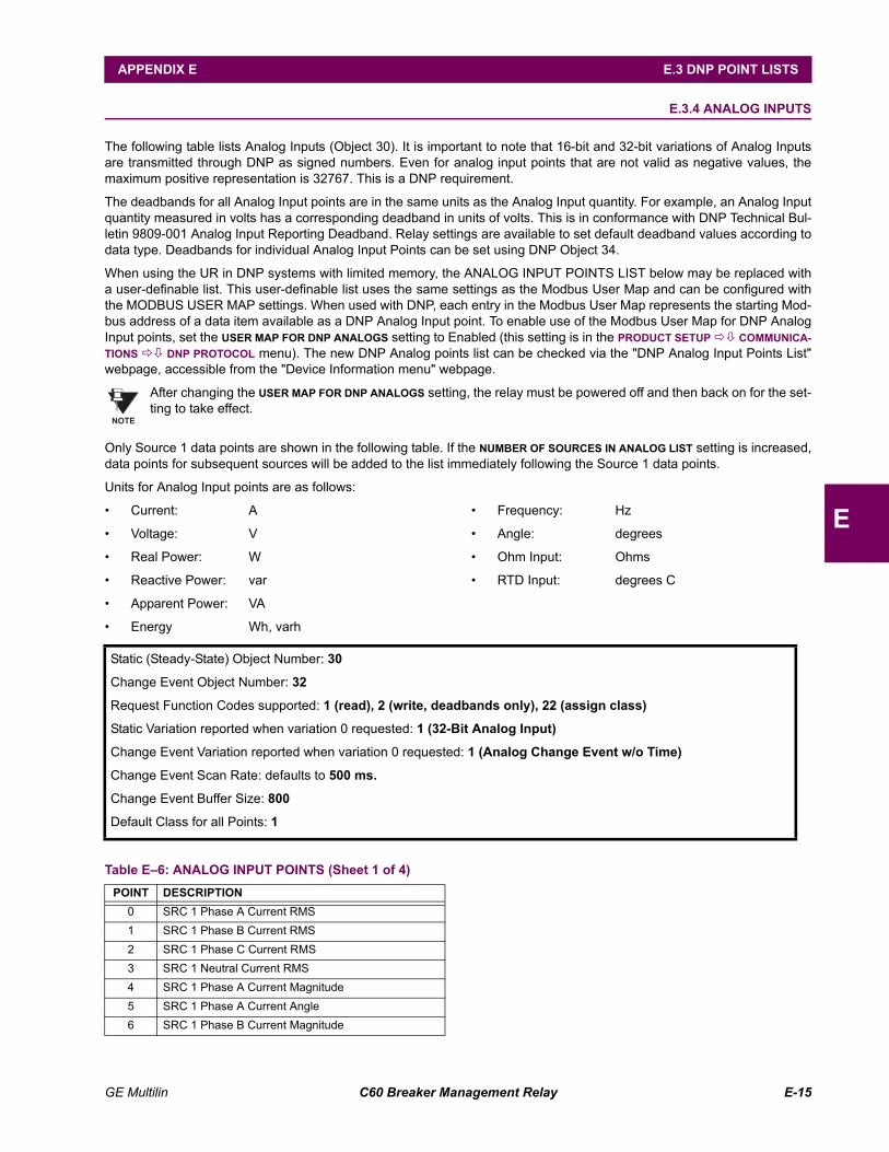
GE Multilin C60 Breaker Management Relay E-15
APPENDIX E E.3 DNP POINT LISTS
E
E.3.4 ANALOG INPUTS
The following table lists Analog Inputs (Object 30). It is important to note that 16-bit and 32-bit variations of Analog Inputsare transmitted through DNP as signed numbers. Even for analog input points that are not valid as negative values, themaximum positive representation is 32767. This is a DNP requirement.
The deadbands for all Analog Input points are in the same units as the Analog Input quantity. For example, an Analog Inputquantity measured in volts has a corresponding deadband in units of volts. This is in conformance with DNP Technical Bul-letin 9809-001 Analog Input Reporting Deadband. Relay settings are available to set default deadband values according todata type. Deadbands for individual Analog Input Points can be set using DNP Object 34.
When using the UR in DNP systems with limited memory, the ANALOG INPUT POINTS LIST below may be replaced witha user-definable list. This user-definable list uses the same settings as the Modbus User Map and can be configured withthe MODBUS USER MAP settings. When used with DNP, each entry in the Modbus User Map represents the starting Mod-bus address of a data item available as a DNP Analog Input point. To enable use of the Modbus User Map for DNP AnalogInput points, set the USER MAP FOR DNP ANALOGS setting to Enabled (this setting is in the PRODUCT SETUP !" COMMUNICA-TIONS !" DNP PROTOCOL menu). The new DNP Analog points list can be checked via the "DNP Analog Input Points List"webpage, accessible from the "Device Information menu" webpage.
After changing the USER MAP FOR DNP ANALOGS setting, the relay must be powered off and then back on for the set-ting to take effect.
Only Source 1 data points are shown in the following table. If the NUMBER OF SOURCES IN ANALOG LIST setting is increased,data points for subsequent sources will be added to the list immediately following the Source 1 data points.
Units for Analog Input points are as follows:
Current: A
Voltage: V
Real Power: W
Reactive Power: var
Apparent Power: VA
Energy Wh, varh
Frequency: Hz
Angle: degrees
Ohm Input: Ohms
RTD Input: degrees C
NOTE
Static (Steady-State) Object Number: 30
Change Event Object Number: 32
Request Function Codes supported: 1 (read), 2 (write, deadbands only), 22 (assign class)
Static Variation reported when variation 0 requested: 1 (32-Bit Analog Input)
Change Event Variation reported when variation 0 requested: 1 (Analog Change Event w/o Time)
Change Event Scan Rate: defaults to 500 ms.
Change Event Buffer Size: 800
Default Class for all Points: 1
Table E6: ANALOG INPUT POINTS (Sheet 1 of 4)POINT DESCRIPTION
0 SRC 1 Phase A Current RMS1 SRC 1 Phase B Current RMS2 SRC 1 Phase C Current RMS3 SRC 1 Neutral Current RMS4 SRC 1 Phase A Current Magnitude5 SRC 1 Phase A Current Angle6 SRC 1 Phase B Current Magnitude
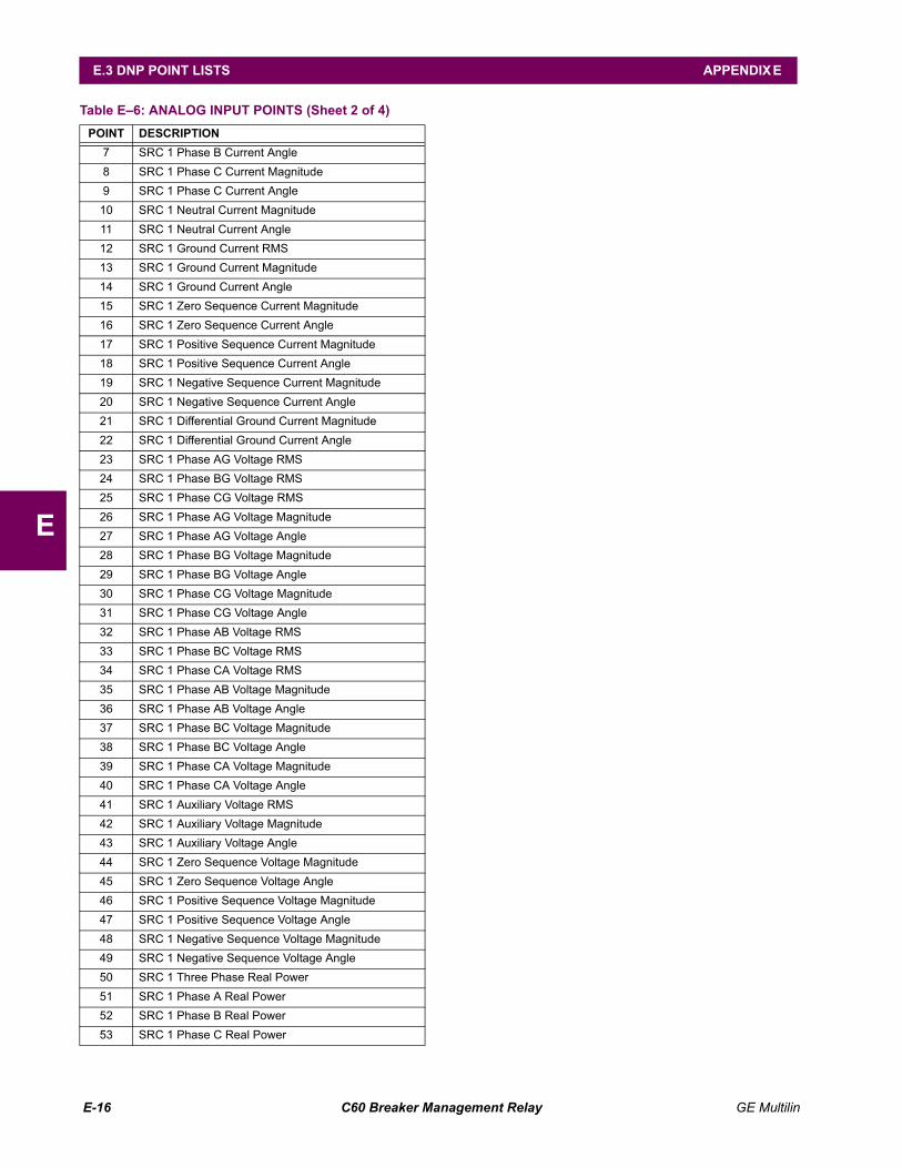
E-16 C60 Breaker Management Relay GE Multilin
E.3 DNP POINT LISTS APPENDIX E
E
7 SRC 1 Phase B Current Angle8 SRC 1 Phase C Current Magnitude9 SRC 1 Phase C Current Angle
10 SRC 1 Neutral Current Magnitude11 SRC 1 Neutral Current Angle12 SRC 1 Ground Current RMS13 SRC 1 Ground Current Magnitude14 SRC 1 Ground Current Angle15 SRC 1 Zero Sequence Current Magnitude16 SRC 1 Zero Sequence Current Angle17 SRC 1 Positive Sequence Current Magnitude18 SRC 1 Positive Sequence Current Angle19 SRC 1 Negative Sequence Current Magnitude20 SRC 1 Negative Sequence Current Angle21 SRC 1 Differential Ground Current Magnitude22 SRC 1 Differential Ground Current Angle23 SRC 1 Phase AG Voltage RMS24 SRC 1 Phase BG Voltage RMS25 SRC 1 Phase CG Voltage RMS26 SRC 1 Phase AG Voltage Magnitude27 SRC 1 Phase AG Voltage Angle28 SRC 1 Phase BG Voltage Magnitude29 SRC 1 Phase BG Voltage Angle30 SRC 1 Phase CG Voltage Magnitude31 SRC 1 Phase CG Voltage Angle32 SRC 1 Phase AB Voltage RMS33 SRC 1 Phase BC Voltage RMS34 SRC 1 Phase CA Voltage RMS35 SRC 1 Phase AB Voltage Magnitude36 SRC 1 Phase AB Voltage Angle37 SRC 1 Phase BC Voltage Magnitude38 SRC 1 Phase BC Voltage Angle39 SRC 1 Phase CA Voltage Magnitude40 SRC 1 Phase CA Voltage Angle41 SRC 1 Auxiliary Voltage RMS42 SRC 1 Auxiliary Voltage Magnitude43 SRC 1 Auxiliary Voltage Angle44 SRC 1 Zero Sequence Voltage Magnitude45 SRC 1 Zero Sequence Voltage Angle46 SRC 1 Positive Sequence Voltage Magnitude47 SRC 1 Positive Sequence Voltage Angle48 SRC 1 Negative Sequence Voltage Magnitude49 SRC 1 Negative Sequence Voltage Angle50 SRC 1 Three Phase Real Power51 SRC 1 Phase A Real Power52 SRC 1 Phase B Real Power53 SRC 1 Phase C Real Power
Table E6: ANALOG INPUT POINTS (Sheet 2 of 4)POINT DESCRIPTION
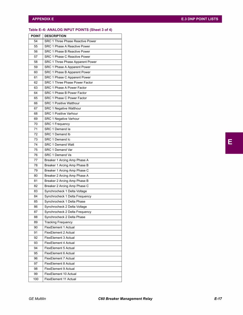
GE Multilin C60 Breaker Management Relay E-17
APPENDIX E E.3 DNP POINT LISTS
E
54 SRC 1 Three Phase Reactive Power55 SRC 1 Phase A Reactive Power56 SRC 1 Phase B Reactive Power57 SRC 1 Phase C Reactive Power58 SRC 1 Three Phase Apparent Power59 SRC 1 Phase A Apparent Power60 SRC 1 Phase B Apparent Power61 SRC 1 Phase C Apparent Power62 SRC 1 Three Phase Power Factor63 SRC 1 Phase A Power Factor64 SRC 1 Phase B Power Factor65 SRC 1 Phase C Power Factor66 SRC 1 Positive Watthour67 SRC 1 Negative Watthour68 SRC 1 Positive Varhour69 SRC 1 Negative Varhour70 SRC 1 Frequency71 SRC 1 Demand Ia72 SRC 1 Demand Ib73 SRC 1 Demand Ic74 SRC 1 Demand Watt75 SRC 1 Demand Var76 SRC 1 Demand Va77 Breaker 1 Arcing Amp Phase A78 Breaker 1 Arcing Amp Phase B79 Breaker 1 Arcing Amp Phase C80 Breaker 2 Arcing Amp Phase A81 Breaker 2 Arcing Amp Phase B82 Breaker 2 Arcing Amp Phase C83 Synchrocheck 1 Delta Voltage84 Synchrocheck 1 Delta Frequency85 Synchrocheck 1 Delta Phase86 Synchrocheck 2 Delta Voltage87 Synchrocheck 2 Delta Frequency88 Synchrocheck 2 Delta Phase89 Tracking Frequency90 FlexElement 1 Actual91 FlexElement 2 Actual92 FlexElement 3 Actual93 FlexElement 4 Actual94 FlexElement 5 Actual95 FlexElement 6 Actual96 FlexElement 7 Actual97 FlexElement 8 Actual98 FlexElement 9 Actual99 FlexElement 10 Actual
100 FlexElement 11 Actual
Table E6: ANALOG INPUT POINTS (Sheet 3 of 4)POINT DESCRIPTION
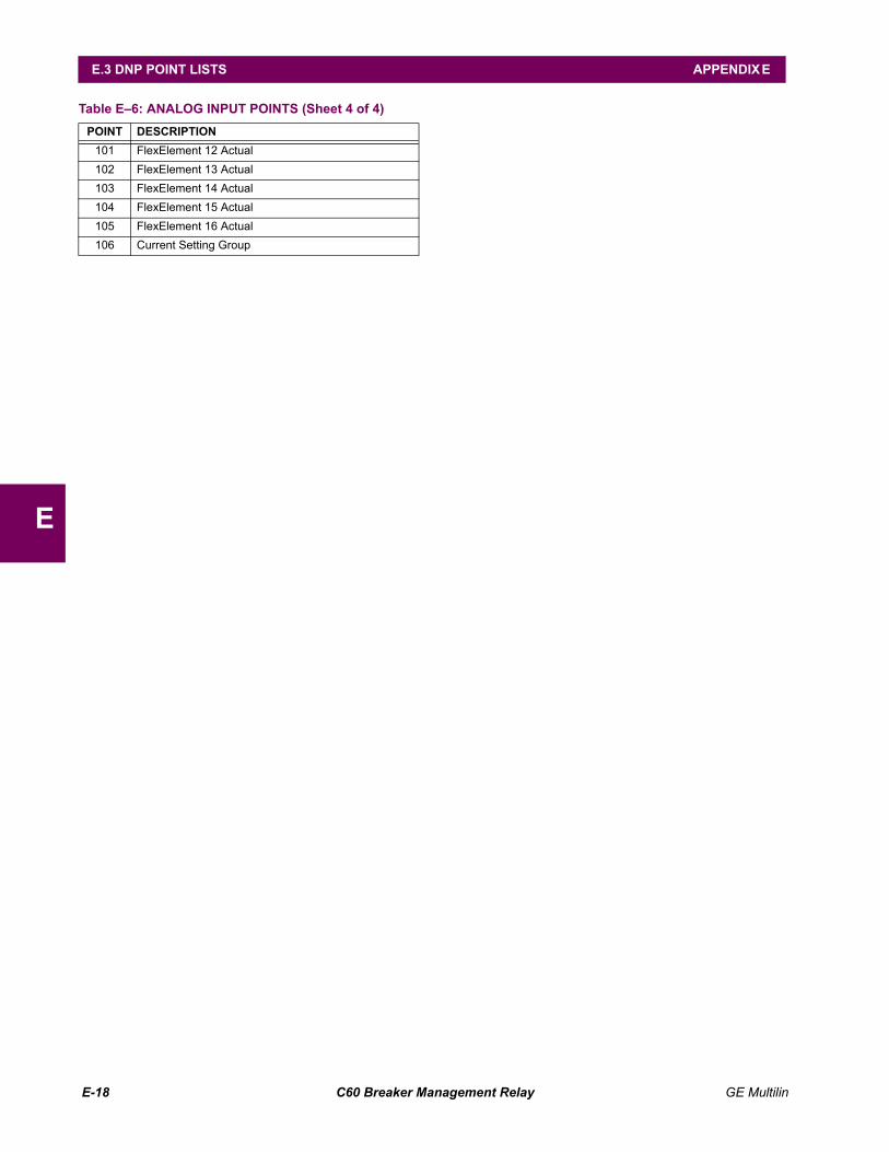
E-18 C60 Breaker Management Relay GE Multilin
E.3 DNP POINT LISTS APPENDIX E
E
101 FlexElement 12 Actual102 FlexElement 13 Actual103 FlexElement 14 Actual104 FlexElement 15 Actual105 FlexElement 16 Actual106 Current Setting Group
Table E6: ANALOG INPUT POINTS (Sheet 4 of 4)POINT DESCRIPTION
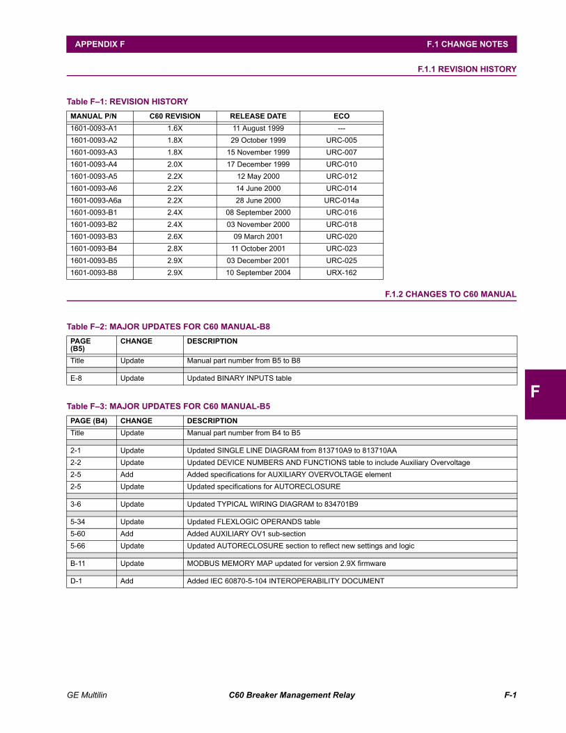
GE Multilin C60 Breaker Management Relay F-1
APPENDIX F F.1 CHANGE NOTES
F
APPENDIX F MISCELLANEOUSF.1 CHANGE NOTES F.1.1 REVISION HISTORY
F.1.2 CHANGES TO C60 MANUAL
Table F1: REVISION HISTORYMANUAL P/N C60 REVISION RELEASE DATE ECO1601-0093-A1 1.6X 11 August 1999 ---1601-0093-A2 1.8X 29 October 1999 URC-0051601-0093-A3 1.8X 15 November 1999 URC-0071601-0093-A4 2.0X 17 December 1999 URC-0101601-0093-A5 2.2X 12 May 2000 URC-0121601-0093-A6 2.2X 14 June 2000 URC-0141601-0093-A6a 2.2X 28 June 2000 URC-014a1601-0093-B1 2.4X 08 September 2000 URC-0161601-0093-B2 2.4X 03 November 2000 URC-0181601-0093-B3 2.6X 09 March 2001 URC-0201601-0093-B4 2.8X 11 October 2001 URC-0231601-0093-B5 2.9X 03 December 2001 URC-0251601-0093-B8 2.9X 10 September 2004 URX-162
Table F2: MAJOR UPDATES FOR C60 MANUAL-B8 PAGE(B5)
CHANGE DESCRIPTION
Title Update Manual part number from B5 to B8
E-8 Update Updated BINARY INPUTS table
Table F3: MAJOR UPDATES FOR C60 MANUAL-B5 PAGE (B4) CHANGE DESCRIPTIONTitle Update Manual part number from B4 to B5
2-1 Update Updated SINGLE LINE DIAGRAM from 813710A9 to 813710AA2-2 Update Updated DEVICE NUMBERS AND FUNCTIONS table to include Auxiliary Overvoltage2-5 Add Added specifications for AUXILIARY OVERVOLTAGE element2-5 Update Updated specifications for AUTORECLOSURE
3-6 Update Updated TYPICAL WIRING DIAGRAM to 834701B9
5-34 Update Updated FLEXLOGIC OPERANDS table5-60 Add Added AUXILIARY OV1 sub-section5-66 Update Updated AUTORECLOSURE section to reflect new settings and logic
B-11 Update MODBUS MEMORY MAP updated for version 2.9X firmware
D-1 Add Added IEC 60870-5-104 INTEROPERABILITY DOCUMENT
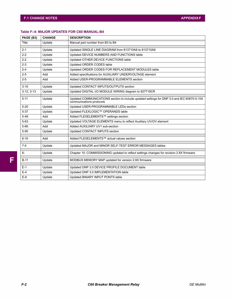
F-2 C60 Breaker Management Relay GE Multilin
F.1 CHANGE NOTES APPENDIX F
F
Table F4: MAJOR UPDATES FOR C60 MANUAL-B4 PAGE (B3) CHANGE DESCRIPTIONTitle Update Manual part number from B3 to B4
2-1 Update Updated SINGLE LINE DIAGRAM from 813710A8 to 813710A92-2 Update Updated DEVICE NUMBERS AND FUNCTIONS table2-2 Update Updated OTHER DEVICE FUNCTIONS table2-3 Update Updated ORDER CODES table2-4 Update Updated ORDER CODES FOR REPLACEMENT MODULES table2-5 Add Added specifications for AUXILIARY UNDERVOLTAGE element2-5 Add Added USER-PROGRAMMABLE ELEMENTS section
3-10 Update Updated CONTACT INPUTS/OUTPUTS section3-12, 3-13 Update Updated DIGITAL I/O MODULE WIRING diagram to 827719CR
5-11 Update Updated COMMUNICATIONS section to include updated settings for DNP 3.0 and IEC 60870-5-104 communications protocols
5-20 Update Updated USER-PROGRAMMABLE LEDs section5-37 Update Updated FLEXLOGIC OPERANDS table5-49 Add Added FLEXELEMENTS settings section5-63 Update Updated VOLTAGE ELEMENTS menu to reflect Auxiliary UV/OV element5-66 Add Added AUXILIARY UV1 sub-section5-90 Update Updated CONTACT INPUTS section
6-16 Add Added FLEXELEMENTS actual values section
7-4 Update Updated MAJOR and MINOR SELF-TEST ERROR MESSAGES tables
8- Update Chapter 10: COMMISSIONING updated to reflect settings changes for revision 2.8X firmware
B-11 Update MODBUS MEMORY MAP updated for version 2.8X firmware
E-1 Update Updated DNP 3.0 DEVICE PROFILE DOCUMENT tableE-4 Update Updated DNP 3.0 IMPLEMENTATION tableE-9 Update Updated BINARY INPUT PONTS table
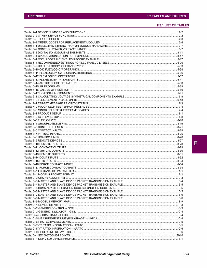
GE Multilin C60 Breaker Management Relay F-3
APPENDIX F F.2 TABLES AND FIGURES
F
F.2 TABLES AND FIGURES F.2.1 LIST OF TABLES
Table: 21 DEVICE NUMBERS AND FUNCTIONS ........................................................................................................................... 2-2Table: 22 OTHER DEVICE FUNCTIONS ......................................................................................................................................... 2-2Table: 23 ORDER CODES .............................................................................................................................................................. 2-3Table: 24 ORDER CODES FOR REPLACEMENT MODULES ...................................................................................................... 2-4Table: 31 DIELECTRIC STRENGTH OF UR MODULE HARDWARE ............................................................................................. 3-7Table: 32 CONTROL POWER VOLTAGE RANGE .......................................................................................................................... 3-7Table: 33 DIGITAL I/O MODULE ASSIGNMENTS......................................................................................................................... 3-11Table: 34 CPU COMMUNICATION PORT OPTIONS .................................................................................................................... 3-17Table: 51 OSCILLOGRAPHY CYCLES/RECORD EXAMPLE ....................................................................................................... 5-17Table: 54 RECOMMENDED SETTINGS FOR LED PANEL 2 LABELS ......................................................................................... 5-20Table: 59 UR FLEXLOGIC OPERAND TYPES ......................................................................................................................... 5-33Table: 510 C60 FLEXLOGIC OPERANDS.................................................................................................................................. 5-34Table: 511 FLEXLOGIC GATE CHARACTERISTICS................................................................................................................. 5-36Table: 512 FLEXLOGIC OPERATORS ..................................................................................................................................... 5-37Table: 513 FLEXELEMENT BASE UNITS .................................................................................................................................. 5-47Table: 514 AUTORECLOSE OPERATION..................................................................................................................................... 5-68Table: 515 AR PROGRAMS ........................................................................................................................................................... 5-69Table: 516 VALUES OF RESISTOR R ......................................................................................................................................... 5-80Table: 517 UCA DNA2 ASSIGNMENTS......................................................................................................................................... 5-91Table: 61 CALCULATING VOLTAGE SYMMETRICAL COMPONENTS EXAMPLE ....................................................................... 6-8Table: 62 FLEXELEMENT BASE UNITS .................................................................................................................................... 6-13Table: 71 TARGET MESSAGE PRIORITY STATUS........................................................................................................................ 7-3Table: 72 MAJOR SELF-TEST ERROR MESSAGES...................................................................................................................... 7-4Table: 73 MINOR SELF-TEST ERROR MESSAGES....................................................................................................................... 7-4Table: 81 PRODUCT SETUP ......................................................................................................................................................... 8-1Table: 82 SYSTEM SETUP .............................................................................................................................................................. 8-8Table: 83 FLEXLOGIC ................................................................................................................................................................ 8-10Table: 84 GROUPED ELEMENTS.................................................................................................................................................. 8-19Table: 85 CONTROL ELEMENTS .................................................................................................................................................. 8-21Table: 86 CONTACT INPUTS......................................................................................................................................................... 8-25Table: 87 VIRTUAL INPUTS........................................................................................................................................................... 8-26Table: 88 UCA SBO TIMER............................................................................................................................................................ 8-26Table: 89 REMOTE DEVICES........................................................................................................................................................ 8-27Table: 810 REMOTE INPUTS......................................................................................................................................................... 8-28Table: 811 CONTACT OUTPUTS................................................................................................................................................... 8-29Table: 812 VIRTUAL OUTPUTS..................................................................................................................................................... 8-30Table: 813 REMOTE OUTPUTS..................................................................................................................................................... 8-31Table: 814 DCMA INPUTS ............................................................................................................................................................. 8-32Table: 815 RTD INPUTS................................................................................................................................................................. 8-33Table: 816 FORCE CONTACT INPUTS......................................................................................................................................... 8-34Table: 817 FORCE CONTACT OUTPUTS..................................................................................................................................... 8-34Table: A1 FLEXANALOG PARAMETERS........................................................................................................................................A-1Table: B1 MODBUS PACKET FORMAT ..........................................................................................................................................B-1Table: B2 CRC-16 ALGORITHM ......................................................................................................................................................B-3Table: B3 MASTER AND SLAVE DEVICE PACKET TRANSMISSION EXAMPLE .........................................................................B-4Table: B4 MASTER AND SLAVE DEVICE PACKET TRANSMISSION EXAMPLE .........................................................................B-5Table: B5 SUMMARY OF OPERATION CODES (FUNCTION CODE 05H) ....................................................................................B-5Table: B6 MASTER AND SLAVE DEVICE PACKET TRANSMISSION EXAMPLE .........................................................................B-5Table: B7 MASTER AND SLAVE DEVICE PACKET TRANSMISSION EXAMPLE .........................................................................B-6Table: B8 MASTER AND SLAVE DEVICE PACKET TRANSMISSION EXAMPLE .........................................................................B-6Table: B9 MODBUS MEMORY MAP................................................................................................................................................B-9Table: C1 DEVICE IDENTITY DI ...................................................................................................................................................C-3Table: C2 GENERIC CONTROL GCTL.........................................................................................................................................C-3Table: C3 GENERIC INDICATOR GIND .......................................................................................................................................C-4Table: C4 GLOBAL DATA GLOBE ................................................................................................................................................C-4Table: C5 MEASUREMENT UNIT (POLYPHASE) MMXU............................................................................................................C-4Table: C6 PROTECTIVE ELEMENTS ..............................................................................................................................................C-5Table: C7 CT RATIO INFORMATION ctRATO..............................................................................................................................C-5Table: C8 VT RATIO INFORMATION vtRATO..............................................................................................................................C-6Table: C9 RECLOSING RELAY RREC .........................................................................................................................................C-6Table: D1 IEC 60870-5-104 POINTS..............................................................................................................................................D-10Table: E1 DNP V3.00 DEVICE PROFILE.........................................................................................................................................E-1
F-4 C60 Breaker Management Relay GE Multilin
F.2 TABLES AND FIGURES APPENDIX F
F
Table: E2 IMPLEMENTATION TABLE .............................................................................................................................................E-4Table: E3 BINARY INPUTS ..............................................................................................................................................................E-8Table: E4 BINARY/CONTROL OUTPUT POINT LIST ...................................................................................................................E-13Table: E5 BINARY and FROZEN COUNTERS ..............................................................................................................................E-14Table: E6 ANALOG INPUT POINTS...............................................................................................................................................E-15Table: F1 REVISION HISTORY........................................................................................................................................................F-1Table: F2 MAJOR UPDATES FOR C60 MANUAL-B5 ....................................................................................................................F-1Table: F3 MAJOR UPDATES FOR C60 MANUAL-B4 ....................................................................................................................F-2
F.2.2 LIST OF FIGURES
Figure 11: REAR NAME-PLATE ....................................................................................................................................................... 1-1Figure 11: REAR NAME-PLATE (EXAMPLE)................................................................................................................................... 1-1Figure 12: UR CONCEPT BLOCK DIAGRAM .................................................................................................................................. 1-3Figure 13: UR SCAN OPERATION................................................................................................................................................... 1-4Figure 14: RELAY COMMUNICATIONS OPTIONS ......................................................................................................................... 1-8Figure 21: SINGLE LINE DIAGRAM ................................................................................................................................................. 2-1Figure 31: C60 VERTICAL MOUNTING AND DIMENSIONS........................................................................................................... 3-1Figure 32: C60 VERTICAL SIDE MOUNTING INSTALLATION ....................................................................................................... 3-2Figure 33: C60 VERTICAL SIDE MOUNTING REAR DIMENSIONS ............................................................................................... 3-3Figure 34: C60 HORIZONTAL MOUNTING AND DIMENSIONS ..................................................................................................... 3-3Figure 35: UR MODULE WITHDRAWAL/INSERTION ..................................................................................................................... 3-4Figure 36: REAR TERMINAL VIEW.................................................................................................................................................. 3-5Figure 37: EXAMPLE OF MODULES IN F & H SLOTS.................................................................................................................... 3-5Figure 38: TYPICAL WIRING DIAGRAM.......................................................................................................................................... 3-6Figure 39: CONTROL POWER CONNECTION................................................................................................................................ 3-8Figure 310: ZERO-SEQUENCE CORE BALANCE CT INSTALLATION .......................................................................................... 3-9Figure 311: CT/VT MODULE WIRING.............................................................................................................................................. 3-9Figure 312: CT MODULE WIRING ................................................................................................................................................... 3-9Figure 313: FORM-A CONTACT FUNCTIONS .............................................................................................................................. 3-10Figure 314: DIGITAL I/O MODULE WIRING (SHEET 1 OF 2) ....................................................................................................... 3-13Figure 315: DIGITAL I/O MODULE WIRING (SHEET 2 OF 2) ....................................................................................................... 3-14Figure 316: DRY AND WET CONTACT INPUT CONNECTIONS .................................................................................................. 3-15Figure 317: TRANSDUCER I/O MODULE WIRING ....................................................................................................................... 3-16Figure 318: RS232 FACEPLATE PORT CONNECTION................................................................................................................ 3-17Figure 319: CPU MODULE COMMUNICATIONS WIRING ............................................................................................................ 3-17Figure 320: RS485 SERIAL CONNECTION ................................................................................................................................... 3-18Figure 321: IRIG-B CONNECTION................................................................................................................................................. 3-19Figure 41: URPC SOFTWARE MAIN WINDOW............................................................................................................................... 4-3Figure 42: UR HORIZONTAL FACEPLATE PANELS ...................................................................................................................... 4-4Figure 43: UR VERTICAL FACEPLATE PANELS ............................................................................................................................ 4-4Figure 44: LED PANEL 1 .................................................................................................................................................................. 4-5Figure 45: LED PANELS 2 AND 3 (INDEX TEMPLATE).................................................................................................................. 4-6Figure 46: LED PANEL 2 DEFAULT LABELS .................................................................................................................................. 4-6Figure 47: LED PANEL CUSTOMIZATION TEMPLATES (EXAMPLE)............................................................................................ 4-8Figure 48: KEYPAD .......................................................................................................................................................................... 4-8Figure 51: BREAKER-AND-A-HALF SCHEME................................................................................................................................. 5-5Figure 52: THERMAL DEMAND CHARACTERISTIC..................................................................................................................... 5-19Figure 53: DISTURBANCE DETECTOR LOGIC DIAGRAM .......................................................................................................... 5-27Figure 54: EXAMPLE USE OF SOURCES..................................................................................................................................... 5-28Figure 55: DUAL BREAKER CONTROL SCHEME LOGIC ............................................................................................................ 5-31Figure 56: UR ARCHITECTURE OVERVIEW ................................................................................................................................ 5-32Figure 57: EXAMPLE LOGIC SCHEME ......................................................................................................................................... 5-38Figure 58: LOGIC EXAMPLE WITH VIRTUAL OUTPUTS ............................................................................................................. 5-39Figure 59: LOGIC FOR VIRTUAL OUTPUT 3 ................................................................................................................................ 5-39Figure 510: LOGIC FOR VIRTUAL OUTPUT 4 .............................................................................................................................. 5-39Figure 511: FLEXLOGIC WORKSHEET ..................................................................................................................................... 5-40Figure 512: FLEXLOGIC EQUATION & LOGIC FOR VIRTUAL OUTPUT 3 .............................................................................. 5-40Figure 513: FLEXLOGIC EQUATION & LOGIC FOR VIRTUAL OUTPUT 4 .............................................................................. 5-42Figure 514: FLEXELEMENT SCHEME LOGIC........................................................................................................................... 5-45Figure 515: FLEXELEMENT DIRECTION, PICKUP, AND HYSTERESIS.................................................................................. 5-46Figure 516: FLEXELEMENT INPUT MODE SETTING ............................................................................................................... 5-46Figure 517: BREAKER FAILURE MAIN PATH SEQUENCE.......................................................................................................... 5-51Figure 518: BREAKER FAILURE 1-POLE [INITIATE] (Sheet 1 of 2) ............................................................................................. 5-54
GE Multilin C60 Breaker Management Relay F-5
APPENDIX F F.2 TABLES AND FIGURES
F
Figure 519: BREAKER FAILURE 1-POLE (TIMERS) [Sheet 2 of 2] .............................................................................................. 5-55Figure 520: BREAKER FAILURE 3-POLE [INITIATE] (Sheet 1 of 2) ............................................................................................. 5-56Figure 521: BREAKER FAILURE 3-POLE [TIMERS] (Sheet 2 of 2) .............................................................................................. 5-57Figure 522: INVERSE TIME UNDERVOLTAGE CURVES............................................................................................................. 5-58Figure 523: PHASE UV1 SCHEME LOGIC .................................................................................................................................... 5-59Figure 524: AUXILIARY UNDERVOLTAGE SCHEME LOGIC....................................................................................................... 5-60Figure 525: AUXILIARY OVERVOLTAGE SCHEME LOGIC ......................................................................................................... 5-61Figure 526: EXAMPLE FLEXLOGIC CONTROL OF A SETTINGS GROUP.............................................................................. 5-62Figure 527: SYNCHROCHECK SCHEME LOGIC.......................................................................................................................... 5-66Figure 528: SINGLE-POLE AUTORECLOSE LOGIC (SHEET 1 OF 3) ......................................................................................... 5-74Figure 529: SINGLE-POLE AUTORECLOSE LOGIC (SHEET 2 OF 3) ......................................................................................... 5-75Figure 530: SINGLE-POLE AUTORECLOSE LOGIC (SHEET 3 OF 3) ......................................................................................... 5-76Figure 531: EXAMPLE RECLOSING SEQUENCE......................................................................................................................... 5-77Figure 532: DIGITAL ELEMENT SCHEME LOGIC ........................................................................................................................ 5-78Figure 533: TRIP CIRCUIT EXAMPLE 1 ........................................................................................................................................ 5-79Figure 534: TRIP CIRCUIT EXAMPLE 2 ........................................................................................................................................ 5-80Figure 535: DIGITAL COUNTER SCHEME LOGIC........................................................................................................................ 5-82Figure 536: ARCING CURRENT MEASUREMENT ....................................................................................................................... 5-84Figure 537: BREAKER ARCING CURRENT SCHEME LOGIC...................................................................................................... 5-84Figure 538: INPUT CONTACT DEBOUNCING MECHANISM AND TIME-STAMPING SAMPLE TIMING .................................... 5-86Figure 539: VIRTUAL INPUTS SCHEME LOGIC........................................................................................................................... 5-87Figure 61: FLOW DIRECTION OF SIGNED VALUES FOR WATTS AND VARS ............................................................................ 6-6Figure 62: UR PHASE ANGLE MEASUREMENT CONVENTION ................................................................................................... 6-7Figure 63: ILLUSTRATION OF THE UR CONVENTION FOR SYMMETRICAL COMPONENTS ................................................... 6-8Figure 64: EQUIVALENT SYSTEM FOR FAULT LOCATION........................................................................................................ 6-14Figure 65: FAULT LOCATOR SCHEME......................................................................................................................................... 6-15
F-6 C60 Breaker Management Relay GE Multilin
F.3 ABBREVIATIONS APPENDIX F
F
F.3 ABBREVIATIONS F.3.1 STANDARD ABBREVIATIONS
A..................... ampereAC .................. alternating currentA/D ................. analog to digitalAE .................. accidental energizationAE .................. application entityAMP ............... ampereANSI............... American National Standards InstituteAR .................. automatic reclosureAUTO ............. automaticAUX................ auxiliaryAVG................ average
BER................ bit error rateBF................... breaker failBFI.................. breaker failure initiateBKR................ breakerBLK ................ blockBLKG.............. blockingBPNT.............. breakpoint of a characteristic
CAP................ capacitorCC .................. coupling capacitorCCVT ............. coupling capacitor voltage transformerCFG................ configure / configurable.CFG............... file name extension for oscillography filesCHK................ checkCHNL ............. channelCLS ................ closeCLSD.............. closedCMND ............ commandCMPRSN........ comparisonCO.................. contact outputCOM............... communicationCOMM............ communicationsCOMP ............ compensatedCONN............. connectionCO-ORD......... coordinationCPU................ central processing unitCRT, CRNT .... currentCT .................. current transformerCVT ................ capacitive voltage transformer
D/A ................. digital to analogDC (dc)........... direct currentDD .................. disturbance detectorDFLT .............. defaultDGNST........... diagnosticsDI.................... digital inputDIFF ............... differentialDIR ................. directionalDISCREP ....... discrepancyDIST ............... distanceDMD ............... demandDPO ............... dropoutDSP................ digital signal processorDTT ................ direct transfer tripDUTT.............. direct under-reaching transfer trip
EPRI............... Electric Power Research Institute.EVT ............... file name extension for event recorder filesEXT ................ extension
F ..................... fieldFAIL................ failureFD .................. fault detectorFDH................ fault detector high-setFDL ................ fault detector low-setFLA................. full load currentFO .................. fiber opticFREQ ............. frequencyFSK ................ frequency-shift keyingFWD ............... forward
G .................... generatorGE .................. General ElectricGND ............... groundGNTR ............. generator
GOOSE.......... general object oriented substation event
HARM ............ harmonic / harmonicsHGF ............... high-impedance ground fault (CT)HIZ ................. high-impedance & arcing groundHMI ................ human-machine interfaceHYB ............... hybrid
I...................... instantaneousI_0.................. zero sequence currentI_1.................. positive sequence currentI_2.................. negative sequence currentIA ................... phase A currentIAB ................. phase A minus B currentIB ................... phase B currentIBC................. phase B minus C currentIC ................... phase C currentICA................. phase C minus A currentID ................... identificationIEEE............... Institute of Electrical & Electronic EngineersIG ................... ground (not residual) currentIgd.................. differential ground currentIN ................... CT residual current (3Io) or inputINC SEQ ........ incomplete sequenceINIT ................ initiateINST............... instantaneousINV................. inverseI/O .................. input/outputIOC ................ instantaneous overcurrentIOV................. instantaneous overvoltageIRIG ............... inter-range instrumentation groupIUV................. instantaneous undervoltage
K0 .................. zero sequence current compensationkA................... kiloAmperekV................... kiloVolt
LED................ light emitting diodeLEO................ line end openLOOP............. loopbackLPU................ line pickupLRA................ locked-rotor currentLTC ................ load tap-changer
M.................... machinemA ................. milliAmpereMAN............... manual / manuallyMMI................ man machine interfaceMMS .............. Manufacturing Message SpecificationMSG............... messageMTA................ maximum torque angleMTR ............... motorMVA ............... MegaVolt-Ampere (total 3-phase)MVA_A........... MegaVolt-Ampere (phase A)MVA_B........... MegaVolt-Ampere (phase B)MVA_C........... MegaVolt-Ampere (phase C)MVAR............. MegaVar (total 3-phase)MVAR_A ........ MegaVar (phase A)MVAR_B ........ MegaVar (phase B)MVAR_C ........ MegaVar (phase C)MVARH .......... MegaVar-HourMW ................ MegaWatt (total 3-phase)MW_A ............ MegaWatt (phase A)MW_B ............ MegaWatt (phase B)MW_C............ MegaWatt (phase C)MWH.............. MegaWatt-Hour
N .................... neutralN/A, n/a.......... not applicableNEG ............... negativeNMPLT........... nameplateNOM .............. nominalNTR ............... neutral
O .................... overOC, O/C ......... overcurrentO/P, Op .......... outputOP.................. operate
GE Multilin C60 Breaker Management Relay F-7
APPENDIX F F.3 ABBREVIATIONS
F
OPER............. operateOPERATG...... operatingO/S................. operating systemOSB................ out-of-step blockingOUT................ outputOV.................. overvoltageOVERFREQ... overfrequencyOVLD ............. overload
P..................... phasePC .................. phase comparison, personal computerPCNT ............. percentPF................... power factor (total 3-phase)PF_A .............. power factor (phase A)PF_B .............. power factor (phase B)PF_C.............. power factor (phase C)PHS................ phasePKP................ pickupPLC ................ power line carrierPOS................ positivePOTT.............. permissive over-reaching transfer tripPRESS........... pressurePROT ............. protectionPSEL.............. presentation selectorpu ................... per unitPUIB............... pickup current blockPUIT............... pickup current tripPUTT.............. permissive under-reaching transfer tripPWM .............. pulse width modulatedPWR............... power
R..................... rate, reverseREM ............... remoteREV................ reverseRI.................... reclose initiateRIP ................. reclose in progressROD ............... remote open detectorRST................ resetRSTR ............. restrainedRTD................ resistance temperature detectorRTU................ remote terminal unitRX (Rx) .......... receive, receiver
s ..................... secondS..................... sensitiveSAT ................ CT saturationSBO................ select before operateSEL ................ select / selector / selectionSENS ............. sensitiveSEQ................ sequenceSIR ................. source impedance ratioSRC................ sourceSSB................ single side bandSSEL.............. session selectorSTATS ............ statisticsSUPN ............. supervision
SUPV..............supervise / supervisionSV...................supervisionSYNCHCHK....synchrocheck
T......................time, transformerTC...................thermal capacityTD MULT ........time dial multiplierTEMP..............temperatureTHD ................total harmonic distortionTOC ................time overcurrentTOV ................time overvoltageTRANS............transientTRANSF .........transferTSEL...............transport selectorTUC ................time undercurrentTUV.................time undervoltageTX (Tx)............transmit, transmitter
U .....................underUC...................undercurrentUCA ................Utility Communications ArchitectureUNBAL............unbalanceUR...................universal relay.URS ...............file name extension for settings filesUV...................undervoltage
V/Hz ................Volts per HertzV_0 .................zero sequence voltageV_1 .................positive sequence voltageV_2 .................negative sequence voltageVA ...................phase A voltageVAB.................phase A to B voltageVAG ................phase A to ground voltageVARH ..............var-hour voltageVB...................phase B voltageVBA.................phase B to A voltageVBG ................phase B to ground voltageVC...................phase C voltageVCA ................phase C to A voltageVCG................phase C to ground voltageVF ...................variable frequencyVIBR ...............vibrationVT ...................voltage transformerVTFF...............voltage transformer fuse failureVTLOS............voltage transformer loss of signal
WDG...............windingWH..................Watt-hourw/ opt ..............with optionWRT................with respect to
X .....................reactanceXDUCER.........transducerXFMR..............transformer
Z......................impedance
F-8 C60 Breaker Management Relay GE Multilin
F.4 WARRANTY APPENDIX F
F
F.4 WARRANTY F.4.1 GE POWER MANAGEMENT WARRANTY
GE MULTILIN RELAY WARRANTYGeneral Electric Multilin Inc. (GE Multilin) warrants each relay it manufactures to be free fromdefects in material and workmanship under normal use and service for a period of 24 months fromdate of shipment from factory.
In the event of a failure covered by warranty, GE Multilin will undertake to repair or replace the relayproviding the warrantor determined that it is defective and it is returned with all transportationcharges prepaid to an authorized service centre or the factory. Repairs or replacement under war-ranty will be made without charge.
Warranty shall not apply to any relay which has been subject to misuse, negligence, accident,incorrect installation or use not in accordance with instructions nor any unit that has been alteredoutside a GE Multilin authorized factory outlet.
GE Multilin is not liable for special, indirect or consequential damages or for loss of profit or forexpenses sustained as a result of a relay malfunction, incorrect application or adjustment.
For complete text of Warranty (including limitations and disclaimers), refer to the GE Multilin Stan-dard Conditions of Sale.
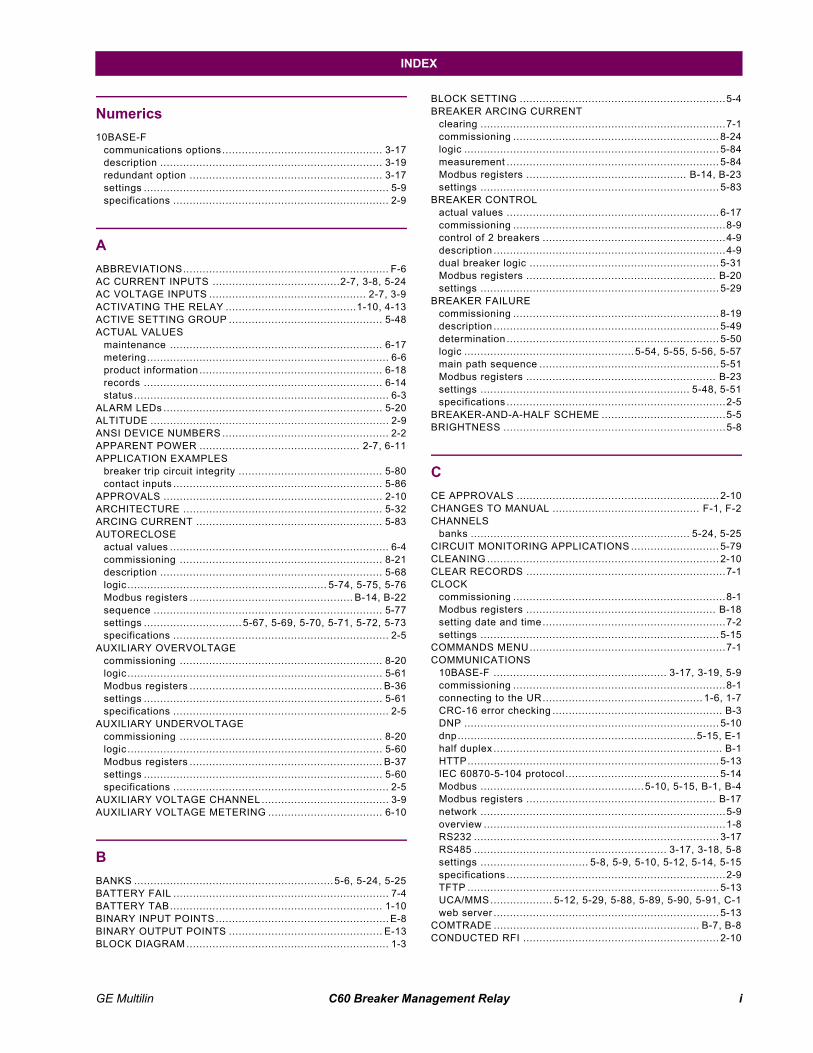
GE Multilin C60 Breaker Management Relay i
INDEX
Numerics10BASE-F
communications options................................................. 3-17description .................................................................... 3-19redundant option ........................................................... 3-17settings ........................................................................... 5-9specifications .................................................................. 2-9
AABBREVIATIONS............................................................... F-6AC CURRENT INPUTS .......................................2-7, 3-8, 5-24AC VOLTAGE INPUTS ................................................ 2-7, 3-9ACTIVATING THE RELAY ........................................1-10, 4-13ACTIVE SETTING GROUP ............................................... 5-48ACTUAL VALUES
maintenance ................................................................. 6-17metering.......................................................................... 6-6product information ........................................................ 6-18records ......................................................................... 6-14status .............................................................................. 6-3
ALARM LEDs ................................................................... 5-20ALTITUDE ......................................................................... 2-9ANSI DEVICE NUMBERS ................................................... 2-2APPARENT POWER ................................................. 2-7, 6-11APPLICATION EXAMPLES
breaker trip circuit integrity ............................................ 5-80contact inputs ................................................................ 5-86
APPROVALS ................................................................... 2-10ARCHITECTURE ............................................................. 5-32ARCING CURRENT ......................................................... 5-83AUTORECLOSE
actual values ................................................................... 6-4commissioning .............................................................. 8-21description .................................................................... 5-68logic ............................................................. 5-74, 5-75, 5-76Modbus registers .................................................. B-14, B-22sequence ...................................................................... 5-77settings .............................. 5-67, 5-69, 5-70, 5-71, 5-72, 5-73specifications .................................................................. 2-5
AUXILIARY OVERVOLTAGEcommissioning .............................................................. 8-20logic .............................................................................. 5-61Modbus registers ........................................................... B-36settings ......................................................................... 5-61specifications .................................................................. 2-5
AUXILIARY UNDERVOLTAGEcommissioning .............................................................. 8-20logic .............................................................................. 5-60Modbus registers ........................................................... B-37settings ......................................................................... 5-60specifications .................................................................. 2-5
AUXILIARY VOLTAGE CHANNEL ....................................... 3-9AUXILIARY VOLTAGE METERING ................................... 6-10
BBANKS .............................................................5-6, 5-24, 5-25BATTERY FAIL .................................................................. 7-4BATTERY TAB................................................................. 1-10BINARY INPUT POINTS..................................................... E-8BINARY OUTPUT POINTS ............................................... E-13BLOCK DIAGRAM .............................................................. 1-3
BLOCK SETTING ...............................................................5-4BREAKER ARCING CURRENT
clearing ...........................................................................7-1commissioning ............................................................... 8-24logic .............................................................................. 5-84measurement ................................................................. 5-84Modbus registers ................................................. B-14, B-23settings ......................................................................... 5-83
BREAKER CONTROLactual values ................................................................. 6-17commissioning .................................................................8-9control of 2 breakers ........................................................4-9description .......................................................................4-9dual breaker logic .......................................................... 5-31Modbus registers .......................................................... B-20settings ......................................................................... 5-29
BREAKER FAILUREcommissioning ............................................................... 8-19description ..................................................................... 5-49determination ................................................................. 5-50logic ....................................................5-54, 5-55, 5-56, 5-57main path sequence ....................................................... 5-51Modbus registers .......................................................... B-23settings ................................................................ 5-48, 5-51specifications ...................................................................2-5
BREAKER-AND-A-HALF SCHEME ......................................5-5BRIGHTNESS ....................................................................5-8
CCE APPROVALS .............................................................. 2-10CHANGES TO MANUAL ............................................. F-1, F-2CHANNELS
banks ................................................................... 5-24, 5-25CIRCUIT MONITORING APPLICATIONS ........................... 5-79CLEANING ....................................................................... 2-10CLEAR RECORDS .............................................................7-1CLOCK
commissioning .................................................................8-1Modbus registers .......................................................... B-18setting date and time........................................................7-2settings ......................................................................... 5-15
COMMANDS MENU............................................................7-1COMMUNICATIONS
10BASE-F ..................................................... 3-17, 3-19, 5-9commissioning .................................................................8-1connecting to the UR................................................. 1-6, 1-7CRC-16 error checking .................................................... B-3DNP .............................................................................. 5-10dnp.........................................................................5-15, E-1half duplex ...................................................................... B-1HTTP............................................................................. 5-13IEC 60870-5-104 protocol ............................................... 5-14Modbus ..................................................5-10, 5-15, B-1, B-4Modbus registers .......................................................... B-17network ...........................................................................5-9overview ..........................................................................1-8RS232 ........................................................................... 3-17RS485 ........................................................... 3-17, 3-18, 5-8settings ................................. 5-8, 5-9, 5-10, 5-12, 5-14, 5-15specifications ...................................................................2-9TFTP ............................................................................. 5-13UCA/MMS................... 5-12, 5-29, 5-88, 5-89, 5-90, 5-91, C-1web server ..................................................................... 5-13
COMTRADE ............................................................... B-7, B-8CONDUCTED RFI ............................................................ 2-10
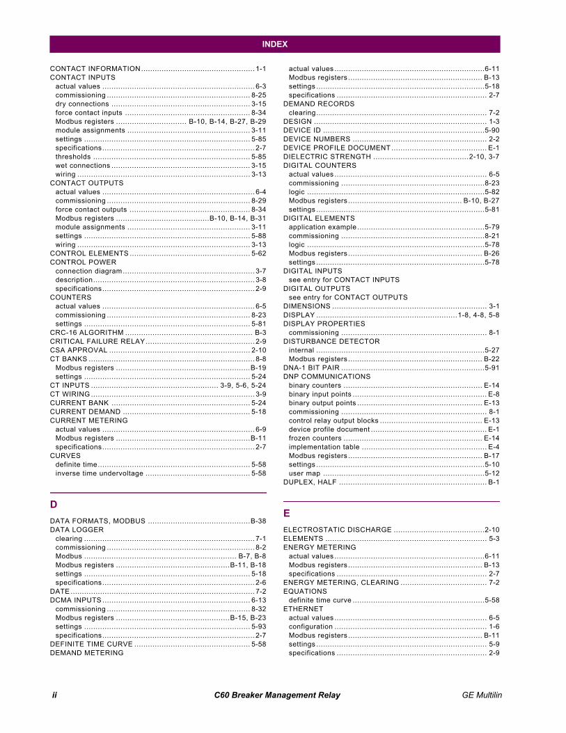
ii C60 Breaker Management Relay GE Multilin
INDEX
CONTACT INFORMATION.................................................. 1-1CONTACT INPUTS
actual values ................................................................... 6-3commissioning ............................................................... 8-25dry connections ............................................................. 3-15force contact inputs ....................................................... 8-34Modbus registers ............................... B-10, B-14, B-27, B-29module assignments ...................................................... 3-11settings ......................................................................... 5-85specifications................................................................... 2-7thresholds ..................................................................... 5-85wet connections ............................................................. 3-15wiring ............................................................................ 3-13
CONTACT OUTPUTSactual values ................................................................... 6-4commissioning ............................................................... 8-29force contact outputs ..................................................... 8-34Modbus registers .........................................B-10, B-14, B-31module assignments ...................................................... 3-11settings ......................................................................... 5-88wiring ............................................................................ 3-13
CONTROL ELEMENTS ..................................................... 5-62CONTROL POWER
connection diagram.......................................................... 3-7description....................................................................... 3-8specifications................................................................... 2-9
COUNTERSactual values ................................................................... 6-5commissioning ............................................................... 8-23settings ......................................................................... 5-81
CRC-16 ALGORITHM ........................................................ B-3CRITICAL FAILURE RELAY................................................ 2-9CSA APPROVAL .............................................................. 2-10CT BANKS ......................................................................... 8-8
Modbus registers ...........................................................B-19settings ......................................................................... 5-24
CT INPUTS ........................................................ 3-9, 5-6, 5-24CT WIRING ........................................................................ 3-9CURRENT BANK ............................................................. 5-24CURRENT DEMAND ........................................................ 5-18CURRENT METERING
actual values ................................................................... 6-9Modbus registers ...........................................................B-11specifications................................................................... 2-7
CURVESdefinite time................................................................... 5-58inverse time undervoltage .............................................. 5-58
DDATA FORMATS, MODBUS .............................................B-38DATA LOGGER
clearing ........................................................................... 7-1commissioning ................................................................. 8-2Modbus ................................................................... B-7, B-8Modbus registers ..................................................B-11, B-18settings ......................................................................... 5-18specifications................................................................... 2-6
DATE ................................................................................. 7-2DCMA INPUTS ................................................................. 6-13
commissioning ............................................................... 8-32Modbus registers ..................................................B-15, B-23settings ......................................................................... 5-93specifications................................................................... 2-7
DEFINITE TIME CURVE ................................................... 5-58DEMAND METERING
actual values ..................................................................6-11Modbus registers ........................................................... B-13settings ..........................................................................5-18specifications .................................................................. 2-7
DEMAND RECORDSclearing........................................................................... 7-2
DESIGN ............................................................................ 1-3DEVICE ID .......................................................................5-90DEVICE NUMBERS ........................................................... 2-2DEVICE PROFILE DOCUMENT .......................................... E-1DIELECTRIC STRENGTH ..........................................2-10, 3-7DIGITAL COUNTERS
actual values ................................................................... 6-5commissioning ...............................................................8-23logic ..............................................................................5-82Modbus registers .................................................. B-10, B-27settings ..........................................................................5-81
DIGITAL ELEMENTSapplication example ........................................................5-79commissioning ...............................................................8-21logic ..............................................................................5-78Modbus registers ........................................................... B-26settings ..........................................................................5-78
DIGITAL INPUTSsee entry for CONTACT INPUTS
DIGITAL OUTPUTSsee entry for CONTACT OUTPUTS
DIMENSIONS .................................................................... 3-1DISPLAY ..............................................................1-8, 4-8, 5-8DISPLAY PROPERTIES
commissioning ................................................................ 8-1DISTURBANCE DETECTOR
internal ..........................................................................5-27Modbus registers ........................................................... B-22
DNA-1 BIT PAIR ...............................................................5-91DNP COMMUNICATIONS
binary counters ............................................................. E-14binary input points ........................................................... E-8binary output points ....................................................... E-13commissioning ................................................................ 8-1control relay output blocks ............................................. E-13device profile document ................................................... E-1frozen counters ............................................................. E-14implementation table ....................................................... E-4Modbus registers ........................................................... B-17settings ..........................................................................5-10user map .......................................................................5-12
DUPLEX, HALF ................................................................. B-1
EELECTROSTATIC DISCHARGE ........................................2-10ELEMENTS ....................................................................... 5-3ENERGY METERING
actual values ..................................................................6-11Modbus registers ........................................................... B-13specifications .................................................................. 2-7
ENERGY METERING, CLEARING ...................................... 7-2EQUATIONS
definite time curve ..........................................................5-58ETHERNET
actual values ................................................................... 6-5configuration ................................................................... 1-6Modbus registers ........................................................... B-11settings ........................................................................... 5-9specifications .................................................................. 2-9
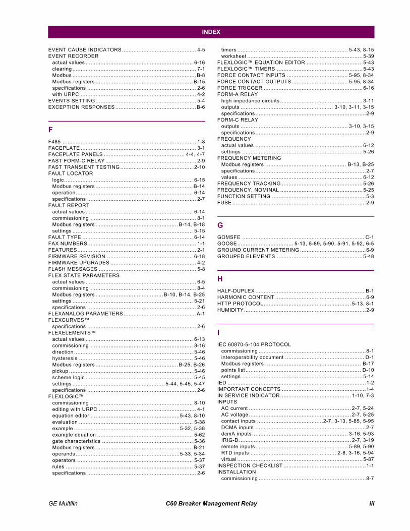
GE Multilin C60 Breaker Management Relay iii
INDEX
EVENT CAUSE INDICATORS............................................. 4-5EVENT RECORDER
actual values ................................................................. 6-16clearing ........................................................................... 7-1Modbus ........................................................................... B-8Modbus registers ........................................................... B-15specifications .................................................................. 2-6with URPC ...................................................................... 4-2
EVENTS SETTING ............................................................. 5-4EXCEPTION RESPONSES ................................................. B-6
FF485 ................................................................................. 1-8FACEPLATE ...................................................................... 3-1FACEPLATE PANELS ................................................. 4-4, 4-7FAST FORM-C RELAY ....................................................... 2-9FAST TRANSIENT TESTING ............................................ 2-10FAULT LOCATOR
logic .............................................................................. 6-15Modbus registers ........................................................... B-14operation....................................................................... 6-14specifications .................................................................. 2-7
FAULT REPORTactual values ................................................................. 6-14commissioning ................................................................ 8-1Modbus registers .................................................. B-14, B-18settings ......................................................................... 5-15
FAULT TYPE ................................................................... 6-14FAX NUMBERS ................................................................. 1-1FEATURES........................................................................ 2-1FIRMWARE REVISION .................................................... 6-18FIRMWARE UPGRADES .................................................... 4-2FLASH MESSAGES ........................................................... 5-8FLEX STATE PARAMETERS
actual values ................................................................... 6-5commissioning ................................................................ 8-4Modbus registers ......................................... B-10, B-14, B-25settings ......................................................................... 5-21specifications .................................................................. 2-6
FLEXANALOG PARAMETERS ............................................ A-1FLEXCURVES
specifications .................................................................. 2-6FLEXELEMENTS
actual values ................................................................. 6-13commissioning .............................................................. 8-16direction ........................................................................ 5-46hysteresis ..................................................................... 5-46Modbus registers .................................................. B-25, B-26pickup ........................................................................... 5-46scheme logic ................................................................. 5-45settings ........................................................ 5-44, 5-45, 5-47specifications .................................................................. 2-6
FLEXLOGICcommissioning .............................................................. 8-10editing with URPC ........................................................... 4-1equation editor ......................................................5-43, 8-10evaluation ..................................................................... 5-38example ................................................................5-32, 5-38example equation .......................................................... 5-62gate characteristics ....................................................... 5-36Modbus registers ........................................................... B-21operands ...............................................................5-33, 5-34operators ...................................................................... 5-37rules ............................................................................. 5-37specifications .................................................................. 2-6
timers ................................................................... 5-43, 8-15worksheet ...................................................................... 5-39
FLEXLOGIC EQUATION EDITOR .................................. 5-43FLEXLOGIC TIMERS .................................................... 5-43FORCE CONTACT INPUTS ..................................... 5-95, 8-34FORCE CONTACT OUTPUTS .................................. 5-95, 8-34FORCE TRIGGER ............................................................ 6-16FORM-A RELAY
high impedance circuits .................................................. 3-11outputs ........................................................ 3-10, 3-11, 3-15specifications ...................................................................2-9
FORM-C RELAYoutputs ................................................................. 3-10, 3-15specifications ...................................................................2-9
FREQUENCYactual values ................................................................. 6-12settings ......................................................................... 5-26
FREQUENCY METERINGModbus registers ................................................. B-13, B-25specifications ...................................................................2-7values ........................................................................... 6-12
FREQUENCY TRACKING ................................................. 5-26FREQUENCY, NOMINAL .................................................. 5-25FUNCTION SETTING .........................................................5-3FUSE .................................................................................2-9
GGOMSFE .......................................................................... C-1GOOSE.................................. 5-13, 5-89, 5-90, 5-91, 5-92, 6-5GROUND CURRENT METERING ........................................6-9GROUPED ELEMENTS .................................................... 5-48
HHALF-DUPLEX .................................................................. B-1HARMONIC CONTENT .......................................................6-9HTTP PROTOCOL ..................................................... 5-13, 8-1HUMIDITY..........................................................................2-9
IIEC 60870-5-104 PROTOCOL
commissioning .................................................................8-1interoperability document ................................................ D-1Modbus registers .......................................................... B-17points list ...................................................................... D-10settings ......................................................................... 5-14
IED ....................................................................................1-2IMPORTANT CONCEPTS ...................................................1-4IN SERVICE INDICATOR........................................... 1-10, 7-3INPUTS
AC current .............................................................. 2-7, 5-24AC voltage .............................................................. 2-7, 5-25contact inputs ........................................2-7, 3-13, 5-85, 5-95DCMA inputs ...................................................................2-7dcmA inputs .......................................................... 3-16, 5-93IRIG-B .................................................................... 2-7, 3-19remote inputs ........................................................ 5-89, 5-90RTD inputs .................................................... 2-8, 3-16, 5-94virtual ............................................................................ 5-87
INSPECTION CHECKLIST ..................................................1-1INSTALLATION
commissioning .................................................................8-7
iv C60 Breaker Management Relay GE Multilin
INDEX
communications ............................................................. 3-17contact inputs/outputs ...................................3-11, 3-13, 3-14CT inputs......................................................................... 3-9Modbus registers ...........................................................B-19RS485 ........................................................................... 3-18settings ......................................................................... 5-23VT inputs ......................................................................... 3-8
INSULATION RESISTANCE.............................................. 2-10INTELLIGENT ELECTRONIC DEVICE................................. 1-2INTRODUCTION ................................................................ 1-2INVERSE TIME UNDERVOLTAGE .................................... 5-58IP ADDRESS ..................................................................... 5-9IRIG-B
connection ..................................................................... 3-19settings ......................................................................... 5-15specifications................................................................... 2-7
ISO-9000 REGISTRATION ............................................... 2-10
KKEYPAD ..................................................................... 1-9, 4-8
LLAMPTEST ........................................................................ 7-2LED INDICATORS ....................................... 4-5, 4-6, 4-7, 5-20LINE
commissioning ................................................................. 8-9Modbus registers ...........................................................B-20settings ......................................................................... 5-28
LINE LENGTH .................................................................. 5-28LOGIC GATES ................................................................. 5-37LOST PASSWORD ............................................................. 5-7
MMAINTENANCE COMMANDS ............................................. 7-2MANUFACTURING DATE ................................................. 6-18MEMORY MAP DATA FORMATS ......................................B-38MENU HEIRARCHY .................................................. 1-9, 4-10MENU NAVIGATION ........................................ 1-9, 4-10, 4-11METERING
conventions .............................................................. 6-6, 6-7current ............................................................................ 2-7demand ........................................................................... 2-7frequency ........................................................................ 2-7power .............................................................................. 2-7voltage ............................................................................ 2-7
METERING CONVENTIONS ............................................... 6-7MIC .................................................................................. C-3MMS
see entry for UCA/MMSMODBUS
data logger .............................................................. B-7, B-8event recorder ................................................................ B-8exception responses ....................................................... B-6execute operation ........................................................... B-5flex state parameters ..................................................... 5-21function code 03/04h ....................................................... B-4function code 05h ........................................................... B-5function code 06h ........................................................... B-5function code 10h ........................................................... B-6introduction .................................................................... B-1memory map data formats ..............................................B-38
obtaining files ................................................................. B-7oscillography ................................................................... B-7passwords ...................................................................... B-8read/write settings/actual values ...................................... B-4settings ................................................................. 5-10, 5-15store multiple settings ..................................................... B-6store single setting .......................................................... B-5supported function codes ................................................. B-4user map .......................................................................5-15
MODEL INFORMATION ....................................................6-18MODIFICATION FILE NUMBER .........................................6-18MODULES
communications .............................................................3-17contact inputs/outputs .................................. 3-11, 3-13, 3-14CT .................................................................................. 3-9CT/VT ...................................................................... 3-8, 5-6insertion.......................................................................... 3-4order codes ..................................................................... 2-4ordering .......................................................................... 2-4power supply ................................................................... 3-7transducer I/O ................................................................3-16VT .................................................................................. 3-9withdrawal ...................................................................... 3-4
MOUNTING ....................................................................... 3-1
NNAMEPLATE ..................................................................... 1-1
OONE SHOTS.....................................................................5-37OPERATING TEMPERATURE ............................................ 2-9OPERATING TIMES .......................................................... 2-5ORDER CODES ........................................................6-18, 7-2ORDER CODES, UPDATING ............................................. 7-2ORDERING ................................................................ 2-3, 2-4OSCILLATORY TRANSIENT TESTING ..............................2-10OSCILLOGRAPHY
actual values ..................................................................6-16clearing........................................................................... 7-1commissioning ................................................................ 8-1Modbus ........................................................................... B-7Modbus registers .................................................. B-14, B-18settings ..........................................................................5-16specifications .................................................................. 2-6with URPC ...................................................................... 4-2
OUTPUTScontact outputs ............................................ 3-11, 3-13, 5-88control power .................................................................. 2-9critical failure relay .......................................................... 2-9Fast Form-C relay ........................................................... 2-9Form-A relay ......................................... 2-9, 3-10, 3-11, 3-15Form-C relay .................................................. 2-9, 3-10, 3-15remote outputs ...................................................... 5-91, 5-92virtual outputs ................................................................5-89
OVERVOLTAGEauxiliary ..................................................................2-5, 5-61
PPANEL CUTOUT ............................................................... 3-1PASSWORD SECURITY ............................................. 5-7, 8-1PASSWORDS
GE Multilin C60 Breaker Management Relay v
INDEX
changing ....................................................................... 4-13lost password ......................................................... 4-14, 5-7Modbus ........................................................................... B-8Modbus registers ........................................................... B-16overview ....................................................................... 1-10security ........................................................................... 5-7settings ........................................................................... 5-7
PC SOFTWAREsee entry for URPC
PERMISSIVE FUNCTIONS ............................................... 5-58PER-UNIT QUANTITY ........................................................ 5-3PHASE ANGLE METERING................................................ 6-7PHASE CURRENT METERING ........................................... 6-9PHASE ROTATION .......................................................... 5-26PHASE UNDERVOLTAGE
commissioning .............................................................. 8-19logic .............................................................................. 5-59Modbus registers ........................................................... B-22settings ......................................................................... 5-59specifications .................................................................. 2-5
PHONE NUMBERS ............................................................ 1-1PICS .................................................................................C-2POWER METERING
Modbus registers ........................................................... B-12specifications .................................................................. 2-7values ........................................................................... 6-10
POWER SUPPLYdescription ...................................................................... 3-7low range ........................................................................ 2-9specifications .................................................................. 2-9
POWER SYSTEMcommissioning ................................................................ 8-8Modbus registers ........................................................... B-20
PRODUCT INFORMATION ............................................... 6-18PRODUCT SETUP ...................................................... 5-7, 8-1PRODUCTION TESTS ..................................................... 2-10PROTECTION ELEMENTS ................................................. 5-3PU QUANTITY ................................................................... 5-3
RREACTIVE POWER .................................................. 2-7, 6-10REAL POWER .......................................................... 2-7, 6-10REAL TIME CLOCK ......................................................... 5-15REAR TERMINAL ASSIGNMENTS ..................................... 3-5RECLOSING
description .................................................................... 5-68logic ............................................................. 5-74, 5-75, 5-76sequence ...................................................................... 5-77settings .............................. 5-67, 5-69, 5-70, 5-71, 5-72, 5-73
REDUNDANT 10BASE-F .................................................. 3-17RELAY ACTIVATION ....................................................... 4-13RELAY ARCHITECTURE.................................................. 5-32RELAY MAINTENANCE ..................................................... 7-2RELAY NAME .................................................................. 5-23RELAY NOT PROGRAMMED ........................................... 1-10REMOTE DEVICES
actual values ................................................................... 6-4commissioning .............................................................. 8-27device ID....................................................................... 5-90Modbus registers ......................................... B-10, B-14, B-32settings ......................................................................... 5-89statistics ......................................................................... 6-5
REMOTE INPUTSactual values ................................................................... 6-3commissioning .............................................................. 8-28
Modbus registers ........................................ B-10, B-14, B-33settings ......................................................................... 5-90
REMOTE OUTPUTScommissioning ............................................................... 8-31DNA-1 bit pair ................................................................ 5-91Modbus registers ................................................. B-33, B-34UserSt-1 bit pair ............................................................ 5-92
REPLACEMENT MODULES ................................................2-4RESETTING ............................................................ 5-92, 8-31REVISION HISTORY ..........................................................F-1RFI SUSCEPTIBILITY ...................................................... 2-10RFI, CONDUCTED ........................................................... 2-10RMS CURRENT .................................................................2-7RMS VOLTAGE ..................................................................2-7ROLLING DEMAND .......................................................... 5-19RS232
configuration ....................................................................1-6specifications ...................................................................2-9wiring ............................................................................ 3-17
RS485communications ............................................................. 3-17description ..................................................................... 3-18specifications ...................................................................2-9
RTD INPUTSactual values ................................................................. 6-13commissioning ............................................................... 8-33Modbus registers ................................................. B-15, B-24settings ......................................................................... 5-94specifications ...................................................................2-8
SSALES OFFICE ..................................................................1-1SCAN OPERATION ............................................................1-4SELF-TESTS
description .......................................................................7-3error messages ................................................................7-4
SERIAL NUMBER ............................................................. 6-18SERIAL PORTS ........................................................5-8, B-17SETTING GROUPS ........................................ 5-48, 5-62, 8-21
Modbus registers .......................................................... B-26SETTINGS, CHANGING ................................................... 4-11SIGNAL SOURCES
commissioning .................................................................8-8description .......................................................................5-4metering ..........................................................................6-9Modbus registers .......................................................... B-20settings ......................................................................... 5-27
SIGNAL TYPES ..................................................................1-3SINGLE LINE DIAGRAM .....................................................2-1SITE LIST, CREATING .......................................................4-1SOFTWARE
see entry for URPCSOFTWARE ARCHITECTURE ............................................1-4SOFTWARE, PC
see entry for URPCSOURCE TRANSFER SCHEMES ...................................... 5-58SOURCES
description .......................................................................5-4example use of .............................................................. 5-27metering ..........................................................................6-9Modbus registers .......................................................... B-11settings ......................................................................... 5-27
SPECIFICATIONS ..............................................................2-5ST TYPE CONNECTORS.................................................. 3-19STANDARD ABBREVIATIONS ............................................F-6
vi C60 Breaker Management Relay GE Multilin
INDEX
STATUS INDICATORS ....................................................... 4-5SURGE IMMUNITY .......................................................... 2-10SYMMETRICAL COMPONENTS METERING ....................... 6-7SYNCHROCHECK
actual values ................................................................. 6-12commissioning ............................................................... 8-21logic .............................................................................. 5-66Modbus registers ...........................................................B-14settings ................................................................ 5-63, 5-64specifications................................................................... 2-5
SYSTEM FREQUENCY .................................................... 5-25SYSTEM SETUP ....................................................... 5-24, 8-8
TTARGET MESSAGES ......................................................... 7-3TARGET SETTING ............................................................. 5-4TARGETS MENU ............................................................... 7-3TCP PORT NUMBER ........................................................ 5-13TEMPERATURE, OPERATING ........................................... 2-9TERMINALS....................................................................... 3-5TEST MODE .................................................................... 5-95TESTING
commissioning ............................................................... 8-34force contact inputs ....................................................... 5-95force contact outputs ..................................................... 5-95lamp test ......................................................................... 7-2self-test error messages ................................................... 7-3test mode ...................................................................... 5-95
TFTP PROTOCOL ..................................................... 5-13, 8-1THERMAL DEMAND CHARACTERISTIC ........................... 5-19TIME ................................................................................. 7-2TIMERS ........................................................................... 5-43TRACKING FREQUENCY ................................................. 6-13TRANSDUCER I/O
actual values ................................................................. 6-13commissioning ...................................................... 8-32, 8-33Modbus registers .........................................B-15, B-23, B-24settings ................................................................ 5-93, 5-94specifications............................................................ 2-7, 2-8wiring ............................................................................ 3-16
TRIP LEDs ....................................................................... 5-20TROUBLE INDICATOR .............................................. 1-10, 7-3TYPE TESTS ................................................................... 2-10TYPICAL WIRING DIAGRAM .............................................. 3-6
UUCA SBO TIMER
for breaker control .................................................. 5-29, 8-9for virtual inputs .................................................... 5-88, 8-26
UCA/MMScommissioning ................................................................. 8-1device ID ....................................................................... 5-90DNA2 assignments ........................................................ 5-91MIC ................................................................................ C-3overview ......................................................................... C-1PICS .............................................................................. C-2remote device settings ................................................... 5-89remote inputs ................................................................ 5-90reporting......................................................................... C-6SBO timeout ......................................................... 5-29, 5-88settings ......................................................................... 5-12UserSt-1 bit pair ............................................................ 5-92
UL APPROVAL................................................................. 2-10
UNDERVOLTAGEauxiliary .......................................................................... 2-5phase .....................................................................2-5, 5-59
UNDERVOLTAGE CHARACTERISTICS .............................5-58UNIT NOT PROGRAMMED ...............................................5-23UNPACKING THE RELAY .................................................. 1-1UPDATING ORDER CODE ................................................. 7-2URPC
creating a site list ............................................................ 4-1event recorder ................................................................. 4-2firmware upgrades ........................................................... 4-2installation ...................................................................... 1-5introduction ..................................................................... 4-1oscillography ................................................................... 4-2overview ......................................................................... 4-1requirements ................................................................... 1-5
USER MAP ............................................................. B-10, B-21USER-DEFINABLE DISPLAYS
commissioning ................................................................ 8-6example .........................................................................5-22settings ..........................................................................5-22specifications .................................................................. 2-6
USER-PROGRAMMABLE LEDscommissioning ................................................................ 8-3custom labeling ............................................................... 4-7defaults........................................................................... 4-6description ...................................................................... 4-6Modbus registers ........................................................... B-18settings ..........................................................................5-20specifications .................................................................. 2-6
USERST-1 BIT PAIR .........................................................5-92
VVAR-HOURS .............................................................2-7, 6-11VIBRATION TESTING .......................................................2-10VIRTUAL INPUTS
actual values ................................................................... 6-3commands ...................................................................... 7-1commissioning ...............................................................8-26logic ..............................................................................5-87Modbus registers .................................................... B-9, B-29settings ..........................................................................5-87
VIRTUAL OUTPUTSactual values ................................................................... 6-4commissioning ...............................................................8-30Modbus registers ........................................................... B-30settings ..........................................................................5-89
VOLTAGE BANKS .....................................................5-25, 8-8VOLTAGE DEVIATIONS ...................................................2-10VOLTAGE ELEMENTS ......................................................5-58VOLTAGE METERING
Modbus registers ........................................................... B-11specifications .................................................................. 2-7values ............................................................................. 6-9
VT BANKSModbus registers ........................................................... B-19
VT INPUTS......................................................... 3-9, 5-6, 5-25VT WIRING ....................................................................... 3-9
WWARRANTY ...................................................................... F-8WATT-HOURS ...........................................................2-7, 6-11WEB SERVER PROTOCOL ........................................5-13, 8-1

GE Multilin C60 Breaker Management Relay vii
INDEX
WEBSITE .......................................................................... 1-1WIRING DIAGRAM ............................................................ 3-6 Z
ZERO SEQUENCE CORE BALANCE ..................................3-9

viii C60 Breaker Management Relay GE Multilin
INDEX