C402 – Sewerage System · CONSTRUCTION SPECIFICATION FOR DEVELOPMENTS AND SUBDIVISIONS C402 –...
37
CONSTRUCTION SPECIFICATION FOR DEVELOPMENTS AND SUBDIVISIONS C402 – SEWERAGE SYSTEM Tamworth Regional Council Page: 1 Revision 0 (301118) CONSTRUCTION SPECIFICATION FOR DEVELOPMENTS AND SUBDIVISIONS C402 – Sewerage System
Transcript of C402 – Sewerage System · CONSTRUCTION SPECIFICATION FOR DEVELOPMENTS AND SUBDIVISIONS C402 –...

CONSTRUCTION SPECIFICATION FOR DEVELOPMENTS AND SUBDIVISIONS C402 – SEWERAGE SYSTEM
Tamworth Regional Council Page: 1 Revision 0 (301118)
CONSTRUCTION SPECIFICATION FOR
DEVELOPMENTS AND SUBDIVISIONS
C402 – Sewerage System

CONSTRUCTION SPECIFICATION FOR DEVELOPMENTS AND SUBDIVISIONS C402 – SEWERAGE SYSTEM
Tamworth Regional Council Page: 2 Revision 0 (301118)
TABLE OF CONTENTS
CLAUSE CONTENTS PAGE
ORIGIN OF DOCUMENT, COPYRIGHT .............................................................................................................. 4
REVISIONS: C402 - SEWERAGE SYSTEM........................................................................................................ 4
GENERAL ............................................................................................................................. 5
C402.01 SCOPE .............................................................................................................................................. 5
C402.02 REFERENCE DOCUMENTS ............................................................................................................ 5
MATERIALS .......................................................................................................................... 8
C402.03 GENERAL ......................................................................................................................................... 8
C402.04 UNPLASTICISED AND MODIFIED PVC (uPVC and PVC-M) PIPE AND FITTINGS ...................... 8
C402.05 POLYETHYLENE (PE) PIPE AND FITTINGS .................................................................................. 8
C402.06 POLYPROPELENE (PP) PIPE AND FITTINGS ............................................................................... 8
C402.07 DUCTILE IRON (DI) PIPE AND FITTINGS ...................................................................................... 9
C402.08 STEEL PIPELINE .............................................................................................................................. 9
C402.09 NOT USED ........................................................................................................................................ 9
C402.10 PREFORMED MAINTENANCE HOLES (MH) .................................................................................. 9
C402.11 PREFORMED MAINTENANCE SHAFTS (MS) AND TERMINAL MAINTENANCE SHAFTS (TMS)
INCLUDING COVER ............................................................................................................................... 9
C402.12 MAINTENANCE HOLE COVERS AND FRAMES ............................................................................ 9
C402.13 STEELWORK .................................................................................................................................... 9
PIPELINE CONSTRUCTION .............................................................................................. 10
C402.14 GENERAL ....................................................................................................................................... 10
C402.15 LOCATION ...................................................................................................................................... 10
C402.16 COVER OVER PIPELINES............................................................................................................. 10
C402.17 CROSSINGS ................................................................................................................................... 11
C402.18 EARTHWORKS .............................................................................................................................. 11
C402.19 MINIMUM TRENCH WIDTH FOR PIPELINES ............................................................................... 12
C402.20 MAXIMUM TRENCH WIDTH .......................................................................................................... 12
C402.21 EXCAVATION DEPTH .................................................................................................................... 13
C402.22 SUPPORT OF EXCAVATION......................................................................................................... 13
C402.23 TRENCH FLOOR PREPARATION AND PIPE BEDDING ............................................................. 13
C402.24 LAYING AND JOINTING OF PIPES ............................................................................................... 14
C402.25 CONNECTIONS TO MAINTENANCE HOLES AND STRUCTURES............................................. 16
C402.26 JUNCTIONS AND PROPERTY CONNECTION SEWERS ............................................................ 17
C402.27 MARKING OF JUNCTIONS AND PROPERTY CONNECTION SEWERS .................................... 17
CONSTRUCTION SPECIFICATION FOR DEVELOPMENTS AND SUBDIVISIONS C402 – SEWERAGE SYSTEM
Tamworth Regional Council Page: 3 Revision 0 (301118)
C402.28 TRENCH STOPS ............................................................................................................................ 18
C402.29 CONCRETE BULKHEADS ............................................................................................................. 18
C402.30 THRUST AND ANCHOR BLOCKS FOR RISING MAINS .............................................................. 19
C402.31 RISING MAIN FITTINGS ................................................................................................................ 20
C402.32 CONCRETE ENCASEMENT .......................................................................................................... 20
C402.33 WRAPPING OF PIPELINES ........................................................................................................... 21
C402.34 CORROSION PROTECTION OF STEEL BOLTS AND NUTS ...................................................... 21
C402.35 CAST-IN-SITU MAINTENANCE HOLES ........................................................................................ 21
C402.36 COVERS AND FRAMES ................................................................................................................ 22
C402.37 NOT USED ...................................................................................................................................... 22
C402.38 PREFORMED MAINTENANCE HOLE AND MAINTENANCE SHAFT SYSTEMS ........................ 22
PIPELINE TESTING AND RESTORATION ........................................................................ 24
C402.39 GENERAL ....................................................................................................................................... 24
C402.40 INITIAL TEST OF GRAVITATION SEWERS .................................................................................. 24
C402.41 INITIAL TEST OF MAINTENANCE HOLES ................................................................................... 25
C402.42 ACCEPTANCE TEST OF GRAVITATION SEWERS AND MAINTENANCE HOLES .................... 25
C402.43 TESTING GRAVITY MAINS WITH COMPRESSED AIR ............................................................... 26
C402.44 ALLOWABLE PRESSURE DROP TIMES ...................................................................................... 27
C402.45 HYDROSTATIC TESTING OF GRAVITY MAINS .......................................................................... 27
C402.46 VISUAL INSPECTION AND MEASUREMENT OF INFILTRATION ............................................... 28
C402.47 TESTING OF RISING MAINS ......................................................................................................... 29
C402.48 BACKFILL AND COMPACTION ..................................................................................................... 30
C402.49 RESTORATION OF SURFACES ................................................................................................... 31
SPECIAL REQUIREMENTS ............................................................................................... 33
CCTV INSPECTION ........................................................................................................................................... 33
C402.50 WHEN IS A CCTV INSPECTION REQUIRED ............................................................................... 33
C402.65 WHAT IS TO BE INSPECTED ........................................................................................................ 33
C402.66 PRE-INSPECTION CRITERIA ........................................................................................................ 33
C402.67 INSPECTION CRITERIA ................................................................................................................ 33
C402.68 ACCEPTANCE CRITERIA .............................................................................................................. 34
C402.69 SUBMISSION .................................................................................................................................. 34
C402.70 IF REMEDIATION WORK IS REQUIRED ...................................................................................... 35
ANNEXURE C402A – PRESSURE TESTING ..................................................................... 36

CONSTRUCTION SPECIFICATION FOR DEVELOPMENTS AND SUBDIVISIONS C402 – SEWERAGE SYSTEM
Tamworth Regional Council Page: 4 Revision 0 (301118)
ORIGIN OF DOCUMENT, COPYRIGHT
This document was originally based on AUS-SPEC - Development Construction Specification C402 - Sewerage System. Substantial parts of the original AUS-SPEC document have been deleted and replaced in the production of this Tamworth Regional Council Specification. The parts of the AUS-SPEC document that remain are still subject to the original copyright.
REVISIONS: C402 - SEWERAGE SYSTEM
REVISION AMENDMENT DETAILS CLAUSES AMENDED DATE ISSUED (The
new version takes effect from this date)
Authorised -Director Regional Services
0 Original Issue 30/11/2018
CONSTRUCTION SPECIFICATION FOR DEVELOPMENTS AND SUBDIVISIONS C402 – SEWERAGE SYSTEM
Tamworth Regional Council Page: 5 Revision 0 (301118)
GENERAL
C402.01 SCOPE
This Specification is for construction of: Suitable Works
(a) Gravitation sewers up to DN600 nominal size;
(b) Common Effluent sewers, both gravity and pressurised;
(c) Rising mains up to DN600 nominal size; and
(d) Standard appurtenances such as maintenance holes, maintenance shafts and property connection sewers.
This Specification excludes the construction activities for: Exclusions
(a) Treatment plants;
(b) Headworks;
(c) Dosing plant; and
(d) Work controlled by others, including overflow management.
The Constructor shall carry out the work and supply materials meeting the requirements of the reference documents except as otherwise specified herein.
Compliance
For the purposes of this Specification, ‘access chambers’ are referred to as “maintenance holes”.
Terminology
Requirements for quality control and testing, including maximum lot sizes and minimum test frequencies, are cited in CQC-Quality Control Requirements Sub-Annexure B14.
Quality
C402.02 REFERENCE DOCUMENTS
Documents referenced in this Specification are listed below whilst being cited in the text in the abbreviated form or code indicated. The Constructor shall possess, or have access to, the documents required to comply with this Specification.
Documents
Where not otherwise specified in the relevant Tamworth Regional Council (TRC) Specifications or the approved design drawings, the Constructor shall use the latest versions of the Reference documentation, including amendments and supplements, listed in the Specifications at the time of the Project approval.
Currency
Where parallel sections or equivalent clauses to the reference SEWERAGE CODE OF AUSTRALIA is called up as part of this Specification, these references are identified by part and section numbers and enclosed in brackets thus (WSA Edition, Part, Section).
Sewerage Code
(a) Tamworth Regional Council (TRC) Specifications
C201 - Control of Traffic.
C211 - Control of Erosion and Sedimentation.
C271 - Minor Concrete Works.
C290 - Road Openings.
C305 - Trenchless Conduit Installation.
CONSTRUCTION SPECIFICATION FOR DEVELOPMENTS AND SUBDIVISIONS C402 – SEWERAGE SYSTEM
Tamworth Regional Council Page: 6 Revision 0 (301118)
(b) Australian Standards
References in this Specification or on the approved design drawings to Australian Standards are noted by their prefix AS or AS/NZS.
AS/NZS 1111 - ISO metric hexagon commercial bolts and screws.
AS/NZS 1112 - ISO metric hexagon nuts, including thin nuts, slotted nuts, and castle nuts.
AS 1152 - Specification for test sieves.
AS/NZS 1260 - PVC pipes and fittings for drain, waste and vent applications.
AS 1272 - Unsintered PTFE tape for thread sealing applications.
AS 1289.5.4.1 - Compaction control test – Dry density ratio, moisture variation and moisture ratio.
AS 1289.5.6.1 - Soil compaction and density tests—Compaction control test—Density index method for a cohesionless material.
AS 1349 - Bourdon tube pressure and vacuum gauges.
AS 1444 - Wrought alloy steels – Standard, hardenability (H) series and hardened and tempered to designated mechanical properties.
AS 1449 - Wrought alloy steels – Stainless and heat-resisting steel plate, sheet and strip.
AS/NZS 1477 - PVC pipes and fittings for pressure applications.
AS 1565 - Copper and copper alloys – Ingots and castings.
AS 1579 - Arc welded steel pipes and fittings for water and wastewater.
AS/NZS 1594 - Hot-rolled steel flat products.
AS 627.4 - Metal finishing – Preparation and pre-treatment of surfaces-Abrasive blast cleaning.
AS 1646 - Elastomeric seals for waterworks purposes.
AS 1657 - Fixed Platforms, walkways, stairways and ladders – Design, construction and installation.
AS 2032 - Code of practice for installation of uPVC pipe systems.
AS 2033 - Installation of polyethylene pipe systems.
AS/NZS 2280 - Ductile iron pressure pipes and fittings.
AS 2528 - Bolts, studbolts and nuts for flanges and other high and low temperature applications.
AS/NZS 2566.1 - Buried flexible pipelines – Structural design.
AS 2837 - Wrought alloy steels – Stainless steel bars and semi-finished products.
AS 3578 - Cast iron non-return valves for general purposes.
AS 3681 - Guidelines for the application of polyethylene sleeving to ductile iron pipelines and fittings.
AS 3972 - Portland and blended cements.
AS 3996 - Metal access covers, road grates and frames.
AS 4058 - Precast concrete pipes (pressure and non-pressure).
AS 4087 - Metallic flanges for waterworks purposes.
AS/NZS 4129 - Fittings for polyethylene (PE) pipes for pressure
CONSTRUCTION SPECIFICATION FOR DEVELOPMENTS AND SUBDIVISIONS C402 – SEWERAGE SYSTEM
Tamworth Regional Council Page: 7 Revision 0 (301118)
applications.
AS/NZS 4130 - Polyethylene (PE) pipes for pressure applications.
AS 4198 - Precast concrete access chambers for sewerage applications (Read ‘maintenance hole’ for ‘access chamber’).
AS/NZS 4321 - Fusion-bonded medium-density polyethylene coating and lining for pipes and fittings.
AS/NZS 4441 - Orientated PVC (PVC-O) pipes for pressure applications.
AS/NZS 4680 - Hot-dip galvanised (zinc) coatings on fabricated ferrous articles.
AS/NZS 4765(Int) - Modified PVC (PVC-M) pipes for pressure applications.
AS 4794 - Non-return valves – Swing check and tilting disc.
AS/NZS 5065 - Polyetheylene and Polypropylene Pipes and fittings for drainage and sewerage application.
(c) TRC Standard Drawings Applicable to this Section
S1201 - Trench/Embedment – Embedment and Trenchfill Typical Arrangement.
S1202 - Trench/Embedment – Standard Embedment for Flexible and Rigid Pipes.
S1206 - Trench/Embedment – Trench Drainage Bulkheads, Trench Stops and Mass Concrete Piers.
S1300 - Maintenance Holes – Pipe Diameter ≤ DN300 Precast Types P1 and P2.
S1308 - Maintenance Holes – Typical Manhole Cover Arrangement.
W1205 - Trench/Embedment – Concrete Thrust Block Details - Sheet 1 of 2.
W1206 - Trench/Embedment – Concrete Thrust Block Details - Sheet 2 of 2.
W1207 - Trench/Embedment – Thrust and Anchor Block Details – Gate Valves and Vertical Bends.
.
(d) Other Publications
TRC Engineering Guidelines for Subdivisions and Developments.
NSW Workcover Excavation Work Code of Practice.
National Construction Code (NCC) 2016 - Volume 3 - Plumbing Code of
Australia.
PWD Safety Guidelines for fixed ladders, stairways, platforms and walkways for use in sewerage treatment works, pumping stations and maintenance holes.
TRC Standard Drawings shall take precedence over ALL other drawings related to the Works.
Precedence
Where any TRC Standard Drawings conflicts with this Specification, the requirements of this Specification shall take precedence. Proposals to deviate from this Specification shall constitute a HOLD POINT.
CONSTRUCTION SPECIFICATION FOR DEVELOPMENTS AND SUBDIVISIONS C402 – SEWERAGE SYSTEM
Tamworth Regional Council Page: 8 Revision 0 (301118)
TRC HOLD POINT
All proposed deviations from the approved design drawings, TRC Standard Drawings, this Specification or the documents referenced within it, shall be submitted for approval to the TRC Representative with supporting evidence at least five (5) working days prior to the work being undertaken.
PROCESS HELD: The lot or element affected by the proposed deviation.
TRC Hold Point
MATERIALS
C402.03 GENERAL
The Constructor shall comply with the requirements of the manufacturer’s recommendations regarding the handling, transport and storage of materials and as further specified in this Specification.
Due Diligence
The Constructor shall not use damaged or defective materials, including coatings and linings, outside the manufacturer’s recommended limits.
Rejection
All gravity reticulation pipes shall be rubber ring (elastomeric), complying with AS 1646, jointed to the type, size and class as shown on the approved design drawings.
Pipes
C402.04 UNPLASTICISED AND MODIFIED PVC (uPVC and PVC-M) PIPE AND FITTINGS
Unplasticised PVC (uPVC) pipes and fittings for gravity systems shall comply with AS/NZS 1260, shall be suitable for rubber rings (elastomeric) joints and shall be of the class SN8 RRJ 3m lengths and size as shown on the approved design drawings.
Non-pressure Pipe PVC
Unplasticised PVC (uPVC), modified PVC (PVC-M) and orientated PVC (PVC-O) pipes and fittings for mains and suction pipes shall comply with AS/NZS 1477, AS/NZS 4765 and AS/NZS4441, shall be suitable for use with rubber ring (elastomeric) seal, complying with AS 1646, joints and shall be of the class and size as shown on the approved design drawings.
Pressure Pipe PVC
PVC pipes and fittings for mains and suction pipes shall be installed in accordance with AS 2032 and AS/NZS 2566.1.
Installation
Pipes and fittings are to be handled and stored protected from sunlight. The Constructor shall provide protection for the pipes and fittings from ultra violet light and damage. The Constructor shall take account of the time for storage and type of shelter.
Protection
C402.05 POLYETHYLENE (PE) PIPE AND FITTINGS
Polyethylene pipe shall comply with AS/NZS 4129 and AS/NZS 4130 and shall be of the class and size shown on the approved design drawings and installed in accordance with AS 2033.
Standard
Jointing shall be by butt thermal fusion or by electrofusion couplings, Compression fittings are not permitted.
Jointing
The Constructor shall provide pipe of the appropriate external diameter consistent with the required internal diameter shown on the approved design drawings.
Internal Diameter
C402.06 POLYPROPELENE (PP) PIPE AND FITTINGS
Polypropylene pipe shall comply with AS/NZS 5065 and AS/NZS 4130 and shall be of the class SN10 RRJ 3m lengths and size shown on the approved design drawings
CONSTRUCTION SPECIFICATION FOR DEVELOPMENTS AND SUBDIVISIONS C402 – SEWERAGE SYSTEM
Tamworth Regional Council Page: 9 Revision 0 (301118)
and installed in accordance with AS 2033 and AS/NZS 2566.2.
C402.07 DUCTILE IRON (DI) PIPE AND FITTINGS
Ductile iron (DI) pipes and fittings shall comply with AS/NZS 2280 and shall be of the class, size and lining, as shown on the approved design drawings, and installed in accordance with AS/NZS 2566.1. Jointing shall be with rubber rings (elastomeric) to the class and type as shown on the approved design drawings.
Standard
Flanges shall be to AS 2129 and AS 4087 with a minimum allowable operating pressure class of PN16 or to the class and size shown on the approved design drawings. Bolts and nuts for flanged joints below ground shall be Grade 316 stainless steel, unless shown otherwise on the approved design drawings. Grade 316 stainless steel bolts and nuts shall have a liberal application of Nickel Anti seize prior to assembly
Flanges
Where corrosive environments have been identified, all pipework shall be sleeved externally with polyethylene sleeving in accordance with the requirements of AS 3681 unless specified otherwise to be coated and lined. All fittings shall be fusion-bonded coated, in accordance with AS/NZS 4321, or wrapped. The Constructor shall wrap all unprotected joints in the trench with a petrolatum tape system approved by the TRC Representative.
Corrosion Protection
C402.08 STEEL PIPELINE
Steel pipelines and fittings shall comply with AS 1579 and AS/NZS 1594 and shall be of the class, size, lining and coating as shown on the approved design drawings.
Standard
The Constructor shall wrap all unprotected joints in the trench with a petrolatum tape system approved by the TRC Representative.
Corrosion Protection
The jointing system shall be rubber ring (elastomeric), complying with AS 1646, unless shown otherwise on the approved design drawings.
Joints
C402.09 NOT USED
C402.10 PREFORMED MAINTENANCE HOLES (MH)
Precast concrete maintenance hole components shall comply with AS 4198 and TRC Standard Drawing S1300.
Standard
C402.11 PREFORMED MAINTENANCE SHAFTS (MS) AND TERMINAL MAINTENANCE SHAFTS (TMS) INCLUDING COVER
Precast concrete maintenance shaft and terminal maintenance shaft components shall comply with AS 4198 and the approved design drawings.
Standard
C402.12 MAINTENANCE HOLE COVERS AND FRAMES
Concrete maintenance hole covers and frames shall comply with AS 4198 and shall be of the size and class as shown on TRC Standard Drawing S1308 and shall have two lifting points.
Concrete
C402.13 STEELWORK
Structural steelwork, including ladders, brackets and covers, complying with AS 1657, shall be abrasive blast cleaned to AS 1627.4, Class 2.5 and hot dip galvanised to AS/NZS 4680.
Corrosion Protection
The Constructor shall supply and install step irons for maintenance holes as shown on TRC Standard Drawing S1300 and whenever the depth to the invert is greater
Step Irons
CONSTRUCTION SPECIFICATION FOR DEVELOPMENTS AND SUBDIVISIONS C402 – SEWERAGE SYSTEM
Tamworth Regional Council Page: 10 Revision 0 (301118)
than 1.2m deep.
PIPELINE CONSTRUCTION
C402.14 GENERAL
The Constructor shall implement traffic control measures in accordance with C201 - Control of Traffic when working within or adjacent to a public road reserve.
Traffic Management
The alignment of the pipeline as shown on the approved design drawings shall not be changed without the prior approval of the TRC Representative. Proposals to deviate from the approved alignment shall constitute a HOLD POINT.
TRC HOLD POINT
The Constructor shall submit all details and justification of any proposed changes to the pipeline alignment for approval to the TRC Representative at least five (5) working days prior to the work being undertaken.
PROCESS HELD: The lot or element affected by the proposed deviation.
TRC Hold Point
C402.15 LOCATION
The location of the sewers, maintenance holes, sizes and grades of sewers, the types of maintenance holes and maintenance hole covers and the classes of pipes shall be as shown on the approved design drawings. The Constructor shall confirm the locations immediately prior to construction.
The Constructor shall commence laying of pipelines at the lower end of the line unless directed otherwise by the TRC Representative. The Constructor shall lay pipelines to grades and locations shown on the approved design drawings.
Unless shown otherwise on the approved design drawings, the horizontal alignment of all sewer mains located within lots adjacent to stormwater pipes shall be laid with a minimum of 0.5m separation between the outside of the sewer main joint and the outside of the stormwater pipe joint.
Pipe Laying Method
Where sewer of different diameters intersect and/or join, the maximum depth of the smaller pipe is to be such that the pipe obverts are at the same level
Sewer of Different Diameters
Refer to TRC’s policy “Sewer – Excavating, Filling or Building Adjacent to or Over Existing Sewer Mains” http://www.tamworth.nsw.gov.au/Council/Council-Publications/General-Policy-Register/General-Policy-Register/default.aspx
The policy outlines circumstances where building over or adjacent to TRC owned sewers is prohibited or allowed in order to prevent the possibility of damage to the sewer.
Excavating, Filling or Building Adjacent to or Over Existing Sewer Mains
C402.16 COVER OVER PIPELINES
The minimum depth of cover to be provided over pipelines shall be in accordance with TRC Standard Drawing S1201.
Minimum Cover
Lesser cover may be permitted where special protection of the pipelines has been shown on the approved design drawings or directed by the TRC Representative.
Greater cover may be provided where special situations occur, such as conflict with
Special Protection
CONSTRUCTION SPECIFICATION FOR DEVELOPMENTS AND SUBDIVISIONS C402 – SEWERAGE SYSTEM
Tamworth Regional Council Page: 11 Revision 0 (301118)
other services or to meet grading requirements.
C402.17 CROSSINGS
Where a pipeline crosses any road, creek or involves features shown on the approved design drawings, under the control of any Authority, the Constructor shall carry out the work in accordance with the requirements of that Authority. The Constructor shall provide written notification to the relevant Authority of the intention to carry out the work, pay the appropriate fees and provide written approval from the Authority to the Developer’s Representative prior to commencement of the work.
For local and regional roads, the Constructor is to obtain a Road Occupancy Licence (ROL) from TRC and undertake all work in accordance with C290 - Road Openings.
Where the road is a classified road, (ie: State or National Highway), the Constructor shall obtain a ROL from the Roads and Maritime Services (RMS), pay the appropriate fees and provide a copy of the ROL to the TRC Representative prior to commencement of the work.
Constructor’s Responsibility
HOLD POINT
Written approval from the relevant Authorities of the intention to carry out the work shall be provided to the Developer’s Representative.
Process Held: Commencement of pipeline crossing work.
Hold Point
Where shown on the approved design drawings, the Constructor shall use trenchless methods for the installation of the sewer mains in accordance with C305 – Trenchless Conduit Installation. The installation of the sewer main by open trenching shall not be permitted over the lengths designated for trenchless installation.
Existing Road Crossings
C402.18 EARTHWORKS
The Constructor shall carry out all excavations for structures and pipelines to the lines, grades and forms shown on the approved design drawings, or as directed by the TRC Representative, within the specified tolerances. The Constructor shall comply with all requirements of the appropriate Authority including having regard for drainage, dewatering, silt control, noise abatement, proximity to existing buildings and generally for the amenity of adjacent owners.
Constructor’s Responsibility
All excavations shall be undertaken in accordance with the NSW Excavation Work Code of Practice. The Constructor shall leave a clear space of 1000mm minimum between the edge of the zone of influence of any excavation. No excavated materials shall be stockpiled against the walls of any building or fence. Topsoil from excavations shall be stockpiled separately and utilised to restore the surface after backfilling.
Excavated Material
At the completion of work each day, the Constructor shall install appropriate safety fencing along the edges of open excavations and any other measures to ensure the public are isolated and protected from open excavations. The Constructor shall provide fenced walkways and vehicular crossways across trenches to maintain access at all times from carriageway to individual properties or within individual properties and advise beforehand all affected residents. All such installations shall be of adequate size and strength and shall be illuminated to prevent accidents.
Public Safety
Access to Property
The Constructor shall locate, protect and repair, as necessary, all services affected by the work at the Constructor’s expense.
Existing Services
The Constructor shall carry out erosion and sedimentation control at all construction sites in accordance with C211 – Control of Erosion and Sedimentation.
Erosion Control
The Constructor shall take account of safety issues and possible wet weather effects to Limiting
CONSTRUCTION SPECIFICATION FOR DEVELOPMENTS AND SUBDIVISIONS C402 – SEWERAGE SYSTEM
Tamworth Regional Council Page: 12 Revision 0 (301118)
limit the extent of excavation left open. Excavations
C402.19 MINIMUM TRENCH WIDTH FOR PIPELINES
The minimum clear width of trench shall be determined as shown on TRC Standard Drawing S1201.
Where the approved design drawings provide for a trench to be excavated across a paved surface, the width of the trench shall be kept to a minimum and the restoration undertaken in accordance with C290 - Road Openings. The wearing course on road surfaces shall be saw cut to avoid damage to the adjacent roadway.
Minimum Disturbance
The Constructor shall widen the trench where necessary for the installation of valves and fittings and protective coating systems.
Widen for Fittings
C402.20 MAXIMUM TRENCH WIDTH
For gravitation sewers or rising mains of pipe materials other than PVC or PE, no restriction shall be placed on the maximum width of trench due to the structural strength of the pipe provided the depth to invert of the pipe does not exceed the depths shown in column (ii) of Table C402.1.
Pipes other than PVC/PE
The Developer’s Representative may, however, restrict the width of trench due to local conditions. The Developer’s Representative shall not restrict the width of trench to less than as shown in column (iii) of Table C402.1.
Width Restrictions
Where the depth to invert exceeds that shown in column (ii) of Table C402.1, the maximum width of trench (outside timbering or sheet piling, if used) to a height of 150mm above the top of the pipe shall be as shown in column (iii) of Table C402.1.
Depth
Nominal Size of Pipe (mm)
(i)
Maximum Depth to Invert, Unlimited Width Trench (m)
(ii)
Maximum Trench Width (mm), Depths Greater than in
Column (ii)
(iii)
150 225 300 375 400 450 525 600
8.0 6.5 5.5 4.5 4.5 4.5 4.0 4.0
750 825 900 975 975 1050 1125 1200
Table C402.1 - Maximum Trench Widths
For gravitation sewers or rising mains of PVC/PE pipe the maximum width of trench from the trench base to a height of 150mm above the top of the pipe shall be the outside diameter of the pipe barrel plus 400mm. However, in timbered or travelling box excavated trenches, the width of trench when measured to the outside of the support used may be increased to a maximum of 580mm plus the outside diameter of the pipe barrel.
PVC/PE Pipe
The Constructor shall supply a method statement of any special construction control, where shown on the approved design drawings, for the approval of the Developer’s Representative.
Special Controls
CONSTRUCTION SPECIFICATION FOR DEVELOPMENTS AND SUBDIVISIONS C402 – SEWERAGE SYSTEM
Tamworth Regional Council Page: 13 Revision 0 (301118)
C402.21 EXCAVATION DEPTH
The Constructor shall excavate trenches to 75mm below the underside of the pipe barrel and socket or coupling or as otherwise shown on the approved design drawings. An additional 50mm shall be added to the depth of bedding material in rock (ie: total depth of bedding =125mm)
75mm Below
The excavation shall be carried out such as to ensure solid and uniform support for each pipe over the whole length of the barrel with chases provided for joints and wrapping.
Pipe Support
C402.22 SUPPORT OF EXCAVATION
The Constructor shall adequately support all excavations in accordance with the requirements of the NSW WorkCover Excavation Code of Practice. Records documenting compliance with this Code, and other Statutory requirements shall be kept on the Works site.
Precaution Against Slips or Falls
The Constructor shall ensure that timber is left in place where its removal may endanger structures in the vicinity of the excavation.
Timber Left in Place
C402.23 TRENCH FLOOR PREPARATION AND PIPE BEDDING
The trench floor shall be prepared in a manner which prevents differential settlement. The floor shall be inspected for rock outcrops, soft spots or loose areas. Where issues are identified the areas shall be either reworked or over excavated and replaced with a cohesive material uniform with the remainder of the trench. Reworked and excavated section of the trench floor shall be compacted to at least the equivalent of the surrounding natural ground.
When excavation and preparation of the trench has been completed the Constructor shall obtain the TRC Representative’s approval prior to commencing the placement of bedding, pipe laying and jointing. Reworked areas shall be identified along with the treatment undertaken. This action constitutes a HOLD POINT.
Approval
TRC HOLD POINT
The floor of the trench shall be inspected by the TRC Representative. Where applicable, supporting documentation verifying conformance shall be made available from the Constructor to the TRC Representative either prior to or during the inspection.
Process Held: Placement of bedding material.
TRC Hold Point
Pipes for gravitation sewers and rising mains (excluding PVC/PE pipes), shall be bedded on non-cohesive material. Pipe bedding shall consist of a non-cohesive Processed Aggregate bedding material, having a minimum thickness of 75mm below the barrel and socket of the pipe and its grading shall meet the material specification requirements shown in Table C402.2:
• Grading shall fall within the specified limits shown in Table C402.2.
• Wet strength shall be greater than 80kN.
• Wet strength / dry strength variation shall not exceed 35%.
Sieve Size (mm) % of Mass Passing
9.5 100
6.7 85-100
Gravity Sewers Pipes, Rising Main Pipes other than PVC/PE
CONSTRUCTION SPECIFICATION FOR DEVELOPMENTS AND SUBDIVISIONS C402 – SEWERAGE SYSTEM
Tamworth Regional Council Page: 14 Revision 0 (301118)
2.36 0-20
0.075 0-2
Table C402.2 - Grading of Bedding Material for Pipes
Alternative sources, complying with AS/NZS 2566.1, may be nominated for approval by the TRC Representative. Use of an alternative source of material shall constitute a HOLD POINT.
TRC HOLD POINT
Alternative sources of bedding material can be nominated by the Constructor for the TRC Representative’s approval, with conformance records demonstrating compliance with AS/NZS 2566.1, at least five (5) working days prior to placement.
Process Held: Placement of bedding material.
TRC Hold Point
For PVC/PE pipes, irrespective of foundation, the material to be used for pipe bedding (underlay a minimum of 100mm below the underside of the pipe barrel and socket, side support and overlay to a minimum depth of 150mm above the top of the pipe) as shown in TRC Standard Drawing S1202 shall be in non-cohesive granular material, either crushed, natural or blended, and its grading shall fall within limits shown in Table C402.2
PVC/PE Pipes
The maximum acceptable grade for all gravitation sewers is 10%. Where sewer mains are laid at grades of 5% to 10%, these mains shall be constructed with trench stops or concrete bulkheads in accordance with C402.28 and C402.29.
Maximum Grade 10 %
C402.24 LAYING AND JOINTING OF PIPES
Unless detailed otherwise in this Specification, the Constructor shall install pipes in accordance with AS 2032, AS 2033, AS/NZS 2566.1 or AS 3690 as appropriate.
Installation
Before being laid, all pipes, fittings, valves, and materials to be used shall be cleaned and examined by the Constructor and, if required by the Developer’s Representative or the TRC Representative, the Constructor shall suspend each one in a sling to enable the Certifying Engineer to inspect it. If directed by the Developer’s Representative or the TRC Representative, the Constructor shall oil valves and repack valve glands.
Examination
The Constructor shall ensure that the interior of the pipeline is clean and free from obstructions. Plugs shall be used to prevent foreign matter entering sections of pipeline which are left uncompleted overnight.
Cleaning
The Constructor shall take all necessary precautions to prevent flotation of pipes during laying, backfilling and initial testing. The Constructor shall remove any temporary supports prior to completion of backfilling.
Flotation
Except where solvent cement joints are needed to make up or install fittings, joints in pipelines shall be flexible, rubber ring (elastomeric) joints (either roll-on rubber ring (elastomeric) or skid type) or, where shown on the approved design drawings, mechanical joints (either fixed flange or bolted gland type).
Joint Type
CONSTRUCTION SPECIFICATION FOR DEVELOPMENTS AND SUBDIVISIONS C402 – SEWERAGE SYSTEM
Tamworth Regional Council Page: 15 Revision 0 (301118)
For pipes with roll-on rubber ring (elastomeric) joints, spigots and sockets shall be clean and dry. The Constructor, after making the joint, shall check that the rubber ring (elastomeric) has rolled in evenly, and, if not, the Constructor shall withdraw the pipe and remake the joint.
Roll-on Rubber Ring
For pipes with skid type rubber ring (elastomeric) joints, only the lubricant specified in writing by the manufacturer shall be applied in making the joint. The Constructor shall make the joint such that the witness mark shall, at no point, be more than 1mm from the end of the socket.
Skid Rubber Ring
Pipes may be cut as needed to suit closing lengths, to remove damaged pipe or fittings or to remove sockets if necessary when jointing a socketed fitting.
Cut Pipes
For field cuts, a mechanical pipe cutter shall be used, except that PVC/PE pipes may be cut using a power saw or a fine-toothed handsaw and mitre box. For field cuts of ductile iron or steel, the Constructor shall ensure that fire-fighting equipment, in working order, is on the Works site prior to the field cuts being made. If the Constructor proposes to use a petrol-engine pipe cutter in an excavation, the Constructor shall ensure that a safe atmosphere is maintained in the excavation at all times. Cuts in the trench shall be checked for plumb, cuts above ground are to be conducted to ensure plumb and checked afterwards.
Pipe Cutting
The Constructor shall prepare the ends of any pipes cut in the field to the manufacturer’s written instructions.
End Preparation
Where pipes are cut in the field, the Constructor shall make a witness mark on the pipe at the length specified by the manufacturer from the end of the pipe. The Constructor shall not use PVC/PE pipes with scored witness marks. Where the same manufacturer does not make spigots and sockets, the Constructor shall refer to the socket manufacturer for the correct marking depth.
Witness Mark
Where PVC pipes are to be joined to pipes of another material, the joints shall be made as follows:
(a) For jointing PVC/PE spigot to VC socket or PVC/PE socket to VC spigot, the Constructor shall use a PVC/PE adaptor shall be used. The joints in both instances shall be made using a ring conforming to AS 1646.
(b) For jointing PVC/PE spigot to ductile iron socket, the Constructor shall use a rubber ring (elastomeric) joint with an adaptor coupling. Ductile iron spigots shall not be joined to PVC/PE sockets.
Different Joints
If the Constructor encounters asbestos cement pipes, work shall cease and the Developer’s Representative and the TRC Representative shall be notified immediately. Constructor’s and/or their nominated sub-contractors are not permitted to deliberately expose or remove asbestos material.
Only appropriately trained personnel shall be permitted to work with asbestos materials and where cutting and disposal of asbestos cement pipes is required, the Constructor shall conform with all relevant WHS requirements.
Existing AC Pipe
Gravitation pipelines shall be constructed to the following tolerances:
(a) The maximum horizontal deviations to either side from the design axis of a pipeline shall be 50mm for all sizes of pipes.
Tolerances
(b) The invert level shall not deviate from the design grade line by more than 10mm.
(c) Shall not be less than the minimum design grade to achieve self cleansing flows
Gravity sewer mains shall not have any deflection at joints, any horizontal or vertical Joint
CONSTRUCTION SPECIFICATION FOR DEVELOPMENTS AND SUBDIVISIONS C402 – SEWERAGE SYSTEM
Tamworth Regional Council Page: 16 Revision 0 (301118)
deflection shall be made at manholes. Only flexibly jointed rising mains shall be permitted to have deflection at joints, such pipelines with gradual changes in alignment or grade shall be laid with the joint being deflected after it has been made. The Constructor shall comply with the manufacturer’s written recommendations in respect of maximum deflection for each joint provided that no joint shall be deflected to such an extent as to impair its effectiveness.
Deflection
The Constructor shall lay pipes for rising mains on continuously rising grades from scour valve to air release valve, notwithstanding any minor irregularities in the ground surface.
Rising Main Grade
Beige or cream detectable identification tape to AS/NZS 2648.1 shall be laid along the line of the rising main, positioned at either the interface between the bedding material and the backfill material, or 150mm above the top of the service when the backfill material is the same as the bedding material.
Rising Main Identification Detectable Tape
Prior to backfilling and compaction operations, the Constructor shall undertake ovality tests of all pipelines for any abnormalities in pipe shape and rectify any unsatisfactory sections found to the satisfaction of the TRC Representative. The test results shall be made available to the TRC Representative. This action constitutes a WITNESS POINT. The TRC Representative shall advise at the time of notification by the Constructor whether the option to inspect the test results is required.
Ovality Testing
TRC WITNESS POINT
Constructor to submit ovality test results to the TRC Representative at least two (2) working days prior to backfilling of any trenches.
Process Held: Backfilling of trenches.
TRC Witness Points
C402.25 CONNECTIONS TO MAINTENANCE HOLES AND STRUCTURES
The Constructor shall connect pipelines to maintenance holes, structures or embedded concrete by means of 600mm long pipes such that two (2) flexible joints are provided, the first joint being at or within 150mm of the face of the structure. Where flexible joints cannot be made with cut pipes, the Constructor shall select pipes from the various lengths provided in order to make the second joint within 300mm of the position shown on the approved design drawings.
Flexible Joints
The Constructor may vary slightly the positions of maintenance holes shown on the approved design drawings, subject to approval from the TRC Representative prior to construction, to suit changes such as erection of structures, growth of flora and installation of services. The positioning of a maintenance hole shall be such as to comply with WHS requirements for access by maintenance staff, providing a proper working area around the top and access into the hole. Once the final position of a maintenance hole has been established, construction shall be subject to the following requirements:
Maintenance Hole Location
(a) For deviations from the design levels of maintenance holes as shown on the approved design drawings or as directed by the TRC Representative during construction, the following tolerances shall apply:
(i) Where the difference in levels between the inlet pipe and the outlet pipe in a maintenance hole is 100mm or less:
Pipe Tolerance
Inlet - nil; + 10mm
Outlet - 10mm; + nil
(ii) Where the difference in levels, as above, is greater than 100mm:
Tolerances
CONSTRUCTION SPECIFICATION FOR DEVELOPMENTS AND SUBDIVISIONS C402 – SEWERAGE SYSTEM
Tamworth Regional Council Page: 17 Revision 0 (301118)
Pipe Tolerance
Inlet - 10mm; + 10mm
Outlet - 10mm; + 10mm
(b) Allowable lateral deviations from the final design position of maintenance holes shall be +/- 300 mm.
TRC shall complete all necessary work on “live” maintenance holes (i.e.: access to the sewer system that is currently in service and new connections to live sewers) unless shown otherwise on the approved design drawings. The Constructor shall liaise with TRC to avoid disruption, delays and possible conflict. (NB: If approved by the TRC Representative, work can be undertaken by the Constructor under supervision by the TRC Representative or nominated TRC Officer).
Work on Live Maintenance Holes
C402.26 JUNCTIONS AND PROPERTY CONNECTION SEWERS
The Constructor shall provide junctions for dead ends and property connection sewers or risers to properties to serve existing and future dwellings in accordance with this Specification and the approved design drawings. Such junctions shall be inserted along pipelines in locations shown on the approved design drawings or directed by the TRC Representative.
Where not shown on the approved design drawings, junctions shall be provided at a depth no deeper than 1.5m as follows (NB: construction of the vertical shaft is not to be undertaken in cases where it would preclude gravity sewer servicing of the entire lot):
Location
(a) For existing dwellings, at the most practical point not outside the property boundary to facilitate the connection, considering existing sewage outlets. Separate connections shall be provided for dual occupancies.
(b) For vacant blocks, at the most practical point not outside the property boundary to facilitate the connection, considering topography and likely positioning of sewage outlets
Junctions for risers shall be encased in 20MPa concrete up to 300mm in accordance with C271 – Minor Concrete Works.
Concrete Encasement
Except where concrete encasement is directed by the TRC Representative, the Constructor shall sand compact backfill around risers to the top of the socket or coupling on the highest branch off the riser, for the full width of trench and for a minimum distance of 500mm upstream and downstream of the riser. Compaction density shall be as for the requirements for the trench pipeline.
Backfill
All property connection sewers and junctions shall have a minimum diameter of 150mm and have a screwed access cap. Property connection sewers shall have a maximum length of 10m.
Property Connection Sewer Caps
C402.27 MARKING OF JUNCTIONS AND PROPERTY CONNECTION SEWERS
The Constructor shall clearly mark the position of each riser, junction or end of a property connection sewer on completion of backfilling. The marking shall be made by one of the following methods but the location of the mark or peg shall be consistent with the method(s) in use by TRC and to the approval of the TRC Representative.
Location
CONSTRUCTION SPECIFICATION FOR DEVELOPMENTS AND SUBDIVISIONS C402 – SEWERAGE SYSTEM
Tamworth Regional Council Page: 18 Revision 0 (301118)
(a) Where the position of a riser, junction or the end of a property connection sewer is at a substantial boundary fence or structure located on the boundary, a neatly stencilled letter "J" 50mm high shall be painted thereon. Underground identification tape, as specified hereafter, shall finish flush with the existing ground surface as close to the boundary fence or structure as possible.
Adjacent to Fence
(b) Elsewhere, the Constructor shall drive into the ground, a red survey peg, 75mm x 50mm x 600mm long at that position, and left flush with the surface of the surrounding ground. The Constructor shall connect the peg to an underground identification tape as specified hereafter.
Peg
(c) As an alternative to providing a red survey peg, the vertical riser can be constructed. The sewer riser is to be marked red, solvent capped, protected from vandalism and easily identifiable for future internal property connection.
Vertical Riser
(d) The Constructor shall tie the identification tape to the junction or end of the property connection sewer and hold the tape in a vertical position during backfilling. The Constructor shall spike the top end of the tape by the junction peg immediately upon completion of backfilling.
Tape Position
(e) Beige or cream detectable marking tape shall be laid along the line of all mains. The tape is to be positioned at either the interface between the bedding material and the backfill material, or 150mm above the top of the service when the backfill material is the same as the bedding material.
Detectable Tape
C402.28 TRENCH STOPS
Where a sewer or rising main is laid on bedding at a grade of 5% to 14%, the Constructor shall construct, as below, trench stops consisting of bags filled with cement stabilised sand and sealed, or concrete bulk heads. Trench stops shall be installed as prescribed by TRC Standard Drawing S1206 or as shown in the approved design drawings.
Grade 5% to 10%
(a) At the socket side of the joint nearest to the position of a stop required in accordance with the formula hereinafter, a recess 100mm deep to suit the width of bag shall be excavated into the bottom of the trench across its full width and into both sidewalls and extend to within 300mm below finished surface level, or up to a maximum 1 metre above the pipe obvert (whichever is the lesser).
(b) The bags shall be placed around and above the pipe, as in (a) above, so as to give close contact with the pipe and to fill the entire space between the excavated recess and the pipe. Bags shall not be placed onto sand bedding.
Spacing
C402.29 CONCRETE BULKHEADS
Where a sewer rising main is installed at a grade of 15% and up to 29%, the Constructor shall construct concrete bulkheads. Where a sewer rising main is installed at a grade 30% to 50%, the Constructor shall construct concrete bulkheads integral with concrete encasement. Where a pipe is installed at a grade of 50% and over, the Constructor shall install the pipe in accordance with the approved design drawings. Bulkheads shall be of 20MPa concrete as prescribed by TRC Standard Drawing S1206, C271 – Minor Concrete Works, and 150mm minimum thickness as follows:
Concrete Bulkheads
Grade 11% to 29% and 30% to 50% and over 50%
(a) Where concrete bedding or encasement to pipe is required, the 150mm thick bulkhead shall be cast integral with the concrete bedding or encasement across the width of trench and shall be keyed into both sidewalls a minimum of 150mm. The bulkhead shall extend to within 300mm below finished surface level, or up to a minimum 1 metre above the pipe obvert (whichever is the lesser).
CONSTRUCTION SPECIFICATION FOR DEVELOPMENTS AND SUBDIVISIONS C402 – SEWERAGE SYSTEM
Tamworth Regional Council Page: 19 Revision 0 (301118)
(b) Where other bedding, or no bedding, is applicable, the bulkhead shall also be keyed into the bottom of the trench 150mm for the full width of trench.
(c) A 75mm nominal diameter drain hole shall be provided in the concrete bulkhead immediately above the top of the encasement bedding or foundation and crushed rock or gravel shall be placed in and at the upstream end of the drain hole to act as a filter. The gravel shall be 10 to 20mm in size within 150mm in all directions upstream and above the invert of the drain hole beyond which another 150mm thick surround of gravel 2 to 10mm in size shall be placed.
TRC WITNESS POINT
The Constructor shall notify the TRC Representative at least two (2) days prior to the placement of concrete for concrete bulkheads for inspection and approval by the TRC Representative.
Process Held: Placement of Concrete.
TRC Witness
Points
Concrete bulkheads shall be installed and spaced as shown in the approved design drawings.
Spacing
C402.30 THRUST AND ANCHOR BLOCKS FOR RISING MAINS
The Constructor shall construct thrust and anchor blocks where shown on the approved design drawings to the dimensions depicted in TRC Standard Drawing W1205, W1206 and W1207 or as otherwise directed by the TRC Representative. The blocks shall be provided at valves, flexibly jointed bends, tees, enlargers and reducers or any other point where unbalanced forces resulting from internal pressures will occur.
Location
The Constructor shall provide permanent thrust blocks of 25MPa concrete in accordance with TRC Standard Drawing W1205 and W1206, such that the thrust blocks bear against undisturbed material normal to the direction of thrust resulting from internal pressures over the bearing area not less than that directed by the TRC Representative.
Thrust Blocks
The Constructor shall provide permanent anchor blocks of 25MPa concrete in accordance with TRC Standard Drawing W1207. Where no detail is provided, the proposed position and dimensions of the anchor block shall be referred to the TRC Representative.
Anchor Blocks
TRC WITNESS POINT
The Constructor shall notify the TRC Representative at least two (2) days prior to the placement of concrete of any thrust blocks and/or anchor blocks for inspection and approval by the TRC Representative.
Process Held: Placement of Concrete.
TRC Witness Points
The Constructor shall provide temporary anchorages adequate to restrain the pipe when under test.
Temporary Anchorage
The Constructor shall obtain the approval of the TRC Representative for the type and use of restrained joints, as an alternative to thrust blocks, in the case of congested service corridors and urgent commissioning
Restrained Joints
CONSTRUCTION SPECIFICATION FOR DEVELOPMENTS AND SUBDIVISIONS C402 – SEWERAGE SYSTEM
Tamworth Regional Council Page: 20 Revision 0 (301118)
C402.31 RISING MAIN FITTINGS
The Constructor shall install rising mains, air release valves and inspection pipes where shown on the approved design drawings or directed by the TRC Representative. All rising mains shall be topped with an appropriate identification tape.
Location
The Constructor shall provide marking plates bearing the letters "AV" for air valves, "SCV" for scour pipes, “SV” for stop valves and "SRM" for sewage rising main at changes of direction, road crossings and at such chainages that the location of the main is marked, at least once each 100m, as specified hereinafter.
Marking Plates
In urban areas, the Constructor shall provide formed kerb impressions for each fitting and road crossing, with lettering to be 75mm high and 15mm wide and placed on top of the kerb with reflective white paint with glass beads. Alternatively, in areas where kerb is existing, a stainless steel kerb marker disc with a central hole for a mushroom head nail or peg to secure the disc to the top of the kerb may be used. The face of the disc shall be stamped or engraved with letters to identify the adjacent service/fitting.
Kerb Impressions & Marker Discs
Where a valve or fitting is at a distance greater than 10m from any existing wall, fence or post to which the notice plate could be conveniently fixed, the Constructor shall provide and set in the ground a post with the relevant marking plate fixed at the top of the post, facing the fitting. The distance to the fitting in metres, to an accuracy of 0.1m, and the size of the main shall be permanently marked or stamped on the plate with legible numbers a minimum 12mm high. The top number gives the distance (in metres) from the plate to the hydrant and the bottom number gives the size (in millimetres) of the sewer main.
Marking Posts
The post shall conform to the following requirements:
(a) The post shall be of sufficient length to be set firmly in place under saturated ground conditions.
(b) When installed, the post shall project 1000mm above the ground, provided that where tall grass or crops are likely to obscure the post, or where directed by the TRC Representative, its height above the ground shall be increased to 1500mm.
(c) The post shall be metal with yellow powder coating.
Post Details
C402.32 CONCRETE ENCASEMENT
The Constructor shall encase in concrete pipes in gravity sewers or rising mains, as shown on the approved design drawings, with less than the specified cover above the top of the pipe barrel, or where directed by the TRC Representative. Concrete shall be 20MPa in accordance with C271 – Minor Concrete Works and have the following minimum dimensions:
(a) For trenches in other than rock: 150mm minimum under, on both sides and on top of the pipe barrel.
(b) For trenches in rock: 100mm minimum under the pipe barrel, 150mm on top of the pipe barrel and for the full width of trench excavated.
Location
In trenches of other than rock or fissured rock, a contraction joint consisting of a layer of bituminous felt 12mm thick shall be formed in the concrete encasement at the face of each socket or at one (1) face of each coupling.
Contraction Joint
Reinforcement in concrete encasement shall be as shown on the approved design drawings.
Reinforcement
CONSTRUCTION SPECIFICATION FOR DEVELOPMENTS AND SUBDIVISIONS C402 – SEWERAGE SYSTEM
Tamworth Regional Council Page: 21 Revision 0 (301118)
C402.33 WRAPPING OF PIPELINES
Where shown on the approved design drawings or directed by the TRC Representative, the Constructor shall enclose a pipeline or a section thereof, in layflat polyethylene sleeving where corrosive soils exist.
The materials to be used shall be high impact resistance polyethylene sleeving of minimum thickness 0.2mm polyethylene film, approved by the TRC Representative, and 50mm wide plastic adhesive tape.
Material Type
The width of the sleeving when flat shall be in accordance with the pipe manufacturer's written recommendations for the size and type of the pipeline which is to be encased. Precautions shall be taken so that exposure to direct sunlight does not exceed 48 hours.
Width
Where necessary to distinguish pipes within close proximity, pipelines shall be identified by colour sleeving, green in colour, or an appropriate identification tape.
Colour
Application of the polyethylene sleeving and plastic adhesive tape shall be in accordance with the pipe manufacturer's written instructions. The Constructor shall take due care not to damage the sleeving during its application or during the backfilling of the trench. Each pipe shall be encased in a length of sleeving overlapped for a minimum of 250mm at each field joint, and the ends of each length of sleeving shall be held in position with at least three (3) circumferential turns of adhesive tape.
As the polyethylene sleeve material covering the pipe will be loose, excess material shall be neatly drawn up around the pipe barrel, folded into an overlap on top of the pipe and held in place by means of strips of plastic tape at approximately one (1) metre intervals. Bends, tapers and similar fittings shall be covered by polyethylene sleeving as specified for the pipes.
The Constructor shall hand wrap valves, hydrants and irregular shaped fittings and joints using flat polyethylene sheets secured with plastic adhesive tape, or other suitable material, to provide an adequate seal. The flat polyethylene sheets may be obtained by splitting suitable lengths of sleeving.
Application
The Constructor shall rectify any damage done to the polyethylene tubing before, during or after backfilling of the trench.
Damage
C402.34 CORROSION PROTECTION OF STEEL BOLTS AND NUTS
The Constructor shall wrap all galvanised steel bolts and nuts, used for installation below ground, of flanges, bolted gland joints, mechanical joints, tapping bands using a tape consisting of Denso or approved equivalent applied in accordance with the manufacturer’s recommendations. Bolts and nuts shall be dry, clean and free from rust immediately before wrapping.
Wrapping
C402.35 CAST-IN-SITU MAINTENANCE HOLES
For all maintenance holes concrete work, the Constructor shall comply with C271 – Minor Concrete Works in relation to the supply and placement of concrete and steel reinforcement, formwork, tolerances, construction joints, curing and protection except as specified below.
Concrete
Cement used in all concrete shall be Type SR to AS 3972. The Constructor may use fly ash additive to a maximum 20%. Cement used shall be no older than three (3) months since manufacture.
Cement Type
The minimum cement content shall be 360 kg/m3 of concrete and the water/cement
ratio of the mix shall not be greater than 0.50 by mass
Minimum Cement Content
CONSTRUCTION SPECIFICATION FOR DEVELOPMENTS AND SUBDIVISIONS C402 – SEWERAGE SYSTEM
Tamworth Regional Council Page: 22 Revision 0 (301118)
C402.36 COVERS AND FRAMES
Covers and frames shall not be warped or twisted. Surfaces shall be finished such that there are no abrupt irregularities and gradual irregularities shall not exceed 3mm. Unformed surfaces shall be finished to produce a surface that is dense, uniform and free from blemishes. Exposed edges shall have a minimum 4mm radius. Covers and frames shall not be delivered to the Works site before satisfactory documentary evidence has been submitted to the TRC Representative that quality tests have been carried out. This action constitutes a HOLD POINT.
Standard
HOLD POINT
Constructor to submit documentary evidence of the quality tests for covers and frames to the Developer’s Representative for approval.
Process Held: Delivery of covers and frames to the Works site.
Hold Point
Tolerances for the dimensions on the COVER shall be - 3mm + NIL. Cover Tolerance
Tolerances for the dimensions on the FRAME shall be -3mm +3mm. Frame Tolerance
Maintenance hole covers shall be seated on a layer of bitumen-impregnated fibreboard, having a cross-section of 25 x 25mm. Alternatively another seating material of a cross-section and composition approved by the TRC Representative may be used.
Cover Seating
Maintenance hole covers shall be finished flush with the surface in roadways, footpaths and paved surfaces of any type. Elsewhere, covers shall be finished 25mm above the surface of the ground where not shown otherwise on the approved design drawings, or such other level as directed by the TRC Representative, in a manner designed to avoid as far as possible, the entry of surface water.
Cover Levels
In locations where shown on the approved design drawings or directed by the TRC Representative, the Constructor shall install a ductile iron cover and frame instead of the standard concrete maintenance hole cover. Where shown on the approved design drawings, the Constructor shall install bolt down frames and covers in areas subjected to 1 in 100 year flooding. Ductile iron covers and frames shall be manufactured in accordance with AS 3996, and shall be installed as necessary, in accordance with the manufacturer's written requirements.
Ductile Iron Cover
C402.37 NOT USED
C402.38 PREFORMED MAINTENANCE HOLE AND MAINTENANCE SHAFT SYSTEMS
If approved by the TRC Representative, preformed systems, complying with the approved design drawings, if any, otherwise complying with AS 3518, AS 3571 or AS 4198 may be used in lieu of cast in-situ systems. Preformed system components shall not be delivered to the Works site before satisfactory documentary evidence has been submitted to the TRC Representative that quality tests have been carried out. This action constitutes a HOLD POINT.
Approval
CONSTRUCTION SPECIFICATION FOR DEVELOPMENTS AND SUBDIVISIONS C402 – SEWERAGE SYSTEM
Tamworth Regional Council Page: 23 Revision 0 (301118)
TRC HOLD POINT
Constructor to submit documentary evidence of the quality tests for preformed maintenance hole and maintenance shaft systems to the TRC Representative for approval.
Process Held: Delivery of preformed maintenance hole and maintenance shaft systems to the Works site.
TRC Hold Point
The Constructor shall supply components that make a watertight system and have a satisfactory surface finish.
Watertight Components
Generally, preformed maintenance holes shall be made up in accordance with the TRC Standard Drawing S1300, with components consisting of a base section, shaft sections of section lengths such as to minimise the number of joints required, a cone section, cover and frame. Make-up Rings may be used between cone sections and frames to make up height differentials. The vertical distance from the top of the surround and the first step is to be 600mm.
Component Assembly
Generally, preformed maintenance shafts shall be made up components consisting of a base section, shaft sections of section lengths such as to minimise the number of joints required, cover and frame.
Maintenance Shafts
The installation of all preformed components shall be in accordance with the manufacturers’ recommended procedures and requirements.
Manufacturers’ Procedures
Backfill for all preformed maintenance holes and maintenance shafts shall be placed and compacted evenly around the maintenance hole to a level 300mm above the top of the highest incoming pipe and for the full width of the excavation. Where, necessary, the Constructor shall import and compact non-cohesive granular material as shown in TRC Standard Drawing S1300.
Backfill

CONSTRUCTION SPECIFICATION FOR DEVELOPMENTS AND SUBDIVISIONS C402 – SEWERAGE SYSTEM
Tamworth Regional Council Page: 24 Revision 0 (301118)
PIPELINE TESTING AND RESTORATION
C402.39 GENERAL
The Constructor shall subject all sewers and maintenance holes to an initial test as soon as practicable after construction and before backfilling is commenced. An acceptance test shall be carried out before the issue of the Subdivision Certificate and not earlier than one (1) month after completion of construction of all sewers and maintenance holes in a section. Sewers or maintenance holes failing any test, shall be repaired and the test repeated. The process of testing, repair of defects and retesting shall continue until a satisfactory test is obtained.
Initial Test Before Backfill
All lines shall be clear and free from soil, slurry, liquids and other foreign substances at the time of initial and acceptance testing.
Cleaning
C402.40 INITIAL TEST OF GRAVITATION SEWERS
The Constructor shall make the initial testing of gravitation sewers with compressed air. Before the initial test is performed, all pipelaying on the section shall be completed, and backfill shall be compacted to the level of the centre of the pipe barrel and TRC Representative notified. This action constitutes a WITNESS POINT. The TRC Representative shall advise at the time of notification by the Constructor whether the option to inspect the initial testing is required.
Compressed Air
TRC WITNESS POINT
The Constructor shall notify the TRC Representative that all pipelaying on the section is completed, backfilled and compacted to the level of the centre of the pipe barrel.
Process Held: The initial test of gravitation sewers.
TRC Witness Point
The initial test may be carried out before risers and/or property connection sewers are constructed so that the main line can be backfilled. However, the Constructor shall carry out an initial test on the risers and property connection sewers as soon as they are completed.
Risers and Property Connection Sewers
Where the TRC Representative approves the construction of pipelines in other than full lengths between maintenance holes, each length of pipeline shall be tested before backfilling together with the downstream portion of the maintenance hole length under construction.
Other Than Full Lengths
The Constructor shall rectify any fault detected and obtain a satisfactory test before the remainder of backfill is placed.
Rectification
The Constructor shall undertake ovality testing as follows: Ovality Testing
(a) All sewers to DN300 shall be tested to determine any excessive ovality using a proving tool approved by the TRC Representative. Ovality testing shall be undertaken after all earthworks on the subdivision are complete and no sooner than 28 days after backfill of trenches has been completed. Sewer pipes having excessive ovality shall be replaced and the line retested.
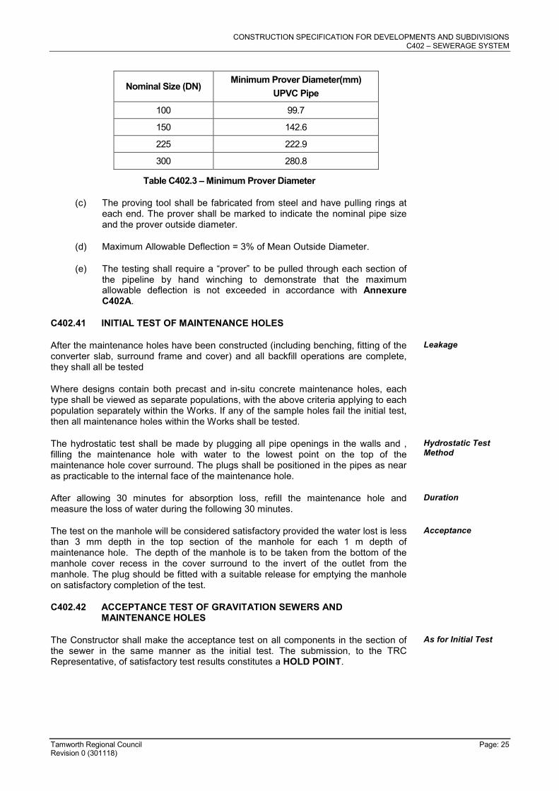
(b) The proving tool shall be rigid and non-adjustable having an effective length of not less than its nominal diameter. The minimum diameter at any point along the length shall be as indicated in Table C402.3:
CONSTRUCTION SPECIFICATION FOR DEVELOPMENTS AND SUBDIVISIONS C402 – SEWERAGE SYSTEM
Tamworth Regional Council Page: 25 Revision 0 (301118)
Nominal Size (DN) Minimum Prover Diameter(mm)
UPVC Pipe
100 99.7
150 142.6
225 222.9
300 280.8
Table C402.3 – Minimum Prover Diameter
(c) The proving tool shall be fabricated from steel and have pulling rings at each end. The prover shall be marked to indicate the nominal pipe size and the prover outside diameter.
(d) Maximum Allowable Deflection = 3% of Mean Outside Diameter.
(e) The testing shall require a “prover” to be pulled through each section of the pipeline by hand winching to demonstrate that the maximum allowable deflection is not exceeded in accordance with Annexure C402A.
C402.41 INITIAL TEST OF MAINTENANCE HOLES
After the maintenance holes have been constructed (including benching, fitting of the converter slab, surround frame and cover) and all backfill operations are complete, they shall all be tested
Leakage
Where designs contain both precast and in-situ concrete maintenance holes, each type shall be viewed as separate populations, with the above criteria applying to each population separately within the Works. If any of the sample holes fail the initial test, then all maintenance holes within the Works shall be tested.
The hydrostatic test shall be made by plugging all pipe openings in the walls and , filling the maintenance hole with water to the lowest point on the top of the maintenance hole cover surround. The plugs shall be positioned in the pipes as near as practicable to the internal face of the maintenance hole.
Hydrostatic Test Method
After allowing 30 minutes for absorption loss, refill the maintenance hole and measure the loss of water during the following 30 minutes.
Duration
The test on the manhole will be considered satisfactory provided the water lost is less than 3 mm depth in the top section of the manhole for each 1 m depth of maintenance hole. The depth of the manhole is to be taken from the bottom of the manhole cover recess in the cover surround to the invert of the outlet from the manhole. The plug should be fitted with a suitable release for emptying the manhole on satisfactory completion of the test.
Acceptance
C402.42 ACCEPTANCE TEST OF GRAVITATION SEWERS AND MAINTENANCE HOLES
The Constructor shall make the acceptance test on all components in the section of the sewer in the same manner as the initial test. The submission, to the TRC Representative, of satisfactory test results constitutes a HOLD POINT.
As for Initial Test
CONSTRUCTION SPECIFICATION FOR DEVELOPMENTS AND SUBDIVISIONS C402 – SEWERAGE SYSTEM
Tamworth Regional Council Page: 26 Revision 0 (301118)
TRC HOLD POINT
Constructor to submit documentary evidence of the satisfactory test results for the section of sewer to the TRC Representative for approval. Approval is required prior to release of the hold point.
Process Held: Acceptance of the test results
TRC Hold Point
The TRC Representative may permit hydrostatic testing as an alternative to compressed air testing for acceptance of gravitation pipelines.
Alternative
The TRC Representative may reject any pipeline or maintenance hole in which there is visible or detectable leakage.
Rejection
C402.43 TESTING GRAVITY MAINS WITH COMPRESSED AIR
The Constructor shall supply and keep all necessary equipment in a condition acceptable to the TRC Representative.
Equipment
The Constructor shall test pressure gauges prior to use by static water column. Pressure Gauges
Compressed air shall be supplied by a compressor of the rotary vane type capable of supplying at least 1 m
3/minute at 35kPa. The air shall be fed through a pressure-
reducing valve capable of reducing pressure from that supplied to 35kPa ± 4kPa. The air shall then pass through an airtight line fitted with a pressure gauge reading from 0 to 50kPa, a pressure relief valve that shall be set to blow off at 35kPa ± 4kPa and a gate valve to the pipeline to be tested.
Compressed Air
The method of setting up and carrying out the test shall be in accordance with AS 2566.2 as follows:
(a) Insert a blank plug at one end and a disc with air-hose connection at the other end of the line. Care shall be taken to ensure that the force due to pressure on the disc is not taken by pipe joints, but is taken by struts bearing on the disc or on the end pipe in the line. Test lengths shall be limited to single pipe runs between maintenance holes.
(b) Couple test equipment to line under test and compressor or airline.
(c) Slowly increase the air pressure in the line from 0 to 28kPa (over one (1) minute approximately). Where the pipeline is below the water table this pressure shall be increased to achieve a differential pressure of 25kPa. In no circumstances shall the actual pressure exceed 50kPa.
(d) Hold air pressure at 28kPa for three (3) minutes for stabilising temperature.
(e) Close gate valve to shut off air supply to test equipment.
(f) Measure the time it takes for the pressure to drop from 25kPa to 18kPa. If this time is less than that permitted or if the line cannot be pressurised to 28kPa, then the test is unsatisfactory and the pipeline shall be checked for leaks.
(g) To check pipelines for leaks:
(h) Open the gate valve from the air supply sufficiently to maintain a pressure of 14kPa to 23kPa in the pipeline.
(i) Move along the pipeline coating it with detergent solution. Bubbles will indicate a point of leakage. Special attention should be paid to joints, discs and horns of junctions.
(j) If leaks are detected, they shall be repaired to the satisfaction of the TRC
Method
CONSTRUCTION SPECIFICATION FOR DEVELOPMENTS AND SUBDIVISIONS C402 – SEWERAGE SYSTEM
Tamworth Regional Council Page: 27 Revision 0 (301118)
Representative.
(k) Re-test as above until the time taken for the pressure to drop is greater than that shown below
C402.44 ALLOWABLE PRESSURE DROP TIMES
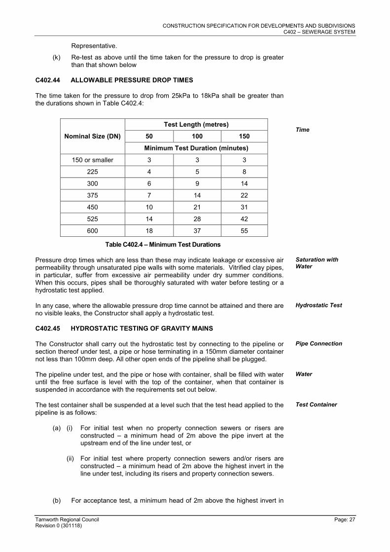
The time taken for the pressure to drop from 25kPa to 18kPa shall be greater than the durations shown in Table C402.4:
Nominal Size (DN)
Test Length (metres)
50 100 150
Minimum Test Duration (minutes)
150 or smaller 3 3 3
225 4 5 8
300 6 9 14
375 7 14 22
450 10 21 31
525 14 28 42
600 18 37 55
Time
Table C402.4 – Minimum Test Durations
Pressure drop times which are less than these may indicate leakage or excessive air permeability through unsaturated pipe walls with some materials. Vitrified clay pipes, in particular, suffer from excessive air permeability under dry summer conditions. When this occurs, pipes shall be thoroughly saturated with water before testing or a hydrostatic test applied.
Saturation with Water
In any case, where the allowable pressure drop time cannot be attained and there are no visible leaks, the Constructor shall apply a hydrostatic test.
Hydrostatic Test
C402.45 HYDROSTATIC TESTING OF GRAVITY MAINS
The Constructor shall carry out the hydrostatic test by connecting to the pipeline or section thereof under test, a pipe or hose terminating in a 150mm diameter container not less than 100mm deep. All other open ends of the pipeline shall be plugged.
Pipe Connection
The pipeline under test, and the pipe or hose with container, shall be filled with water until the free surface is level with the top of the container, when that container is suspended in accordance with the requirements set out below.
Water
The test container shall be suspended at a level such that the test head applied to the pipeline is as follows:
Test Container
(a) (i) For initial test when no property connection sewers or risers are constructed – a minimum head of 2m above the pipe invert at the upstream end of the line under test, or
(ii) For initial test where property connection sewers and/or risers are constructed – a minimum head of 2m above the highest invert in the line under test, including its risers and property connection sewers.
(b) For acceptance test, a minimum head of 2m above the highest invert in
CONSTRUCTION SPECIFICATION FOR DEVELOPMENTS AND SUBDIVISIONS C402 – SEWERAGE SYSTEM
Tamworth Regional Council Page: 28 Revision 0 (301118)
the line under test, including its risers and property connection sewers, or above the free-standing level of ground-water in the vicinity whichever is the higher.
(c) Such other lesser head, at the TRC Representative’s discretion, may direct.
The Constructor shall determine, at the Constructor’s expense, the free-standing level of groundwater, by a method acceptable to the TRC Representative.
Ground-Water
After allowing an interval of 2 hours for absorption, any fall of the free water surface shall be made good by adding extra water to the container. The Constructor shall measure the fall in water level during ten (10) minutes thereafter.
Extra Water
The pipeline will be regarded as satisfactory if there are no visible leaks, and if the fall in water level is not more than 25mm for each standard test length of the pipeline under test including property connection sewers and/or risers.
Results
A standard test length in metres is defined as 1370m divided by the effective diameter of the pipeline in millimetres. Where the pipeline under test is all of the same size, the effective diameter shall be the nominal size of that pipeline. Where the pipeline under test has property connection sewers and/or risers of smaller nominal size than the main sewer line, then the effective diameter shall be calculated as the product of the length and the nominal size of the larger pipe added to the product of the length and the nominal size of the smaller pipe; this sum shall be divided by the total length of pipeline under test; the result shall be the effective diameter.
Test Length
C402.46 VISUAL INSPECTION AND MEASUREMENT OF INFILTRATION
Whenever, in the case of acceptance testing, the pipeline is subjected to a significant head of groundwater (i.e. 1500mm or more above the soffit of the sewer main provided that groundwater is at least 150mm above any property connection sewer included in the test), the tests previously prescribed may be dispensed with in favour of visual inspection and measurement of infiltration.
Head of Groundwater
In such circumstances, the Constructor shall propose full details of the method by which the infiltration is to be measured.
Method
If the TRC Representative, at the TRC Representative’s discretion, approves of an inspection and infiltration test being performed for the purposes of acceptance, the TRC Representative shall determine, the duration over which infiltration is to be measured. The rate of infiltration shall not exceed that determined by the following formula:
Rate of Infiltration
Where: Q.I. = 0.65 (L1d1h1 + L2d2h2 + .......... Lndnhn) + Ha
Q.I. = rate of infiltration (litres/hour).
L = length of pipe (m).
d = nominal size of pipe(m).
h = average head of groundwater over the invert level of the pipe in the section under test.
Ha = head of groundwater above the invert level of the outlet pipe of the maintenance hole when the maintenance hole is included in the infiltration test.
The Constructor shall determine the head of groundwater, at the Constructor’s expense, by a method approved by the TRC Representative.
Constructor’s Cost

CONSTRUCTION SPECIFICATION FOR DEVELOPMENTS AND SUBDIVISIONS C402 – SEWERAGE SYSTEM
Tamworth Regional Council Page: 29 Revision 0 (301118)
C402.47 TESTING OF RISING MAINS
The Constructor shall pressure test rising mains to detect leakage and defects in the pipeline including joints, thrust and anchor blocks. No testing should be commenced until all utility services (e.g. electricity, telecommunications, gas) have been installed in the area. The submission, to the TRC Representative of satisfactory test results constitutes a HOLD POINT.
TRC HOLD POINT
Constructor to submit documentary evidence of the test results for the rising mains to the TRC Representative for approval.
Process Held: Acceptance of the test results
TRC Hold Point
Pipelines shall be tested in sections approved by the TRC Representative as soon as practicable after each section has been laid, jointed and backfilled, provided that:
Timing
(a) If so specified or if the Constructor so desires, some or all of the pipe joints shall be left uncovered until the whole of the section has been successfully pressure tested to the satisfaction of the TRC Representative; and
(b) The pressure testing shall not be commenced earlier than seven (7) days after the last concrete thrust or anchor block in the section has been cast.
For the purpose of this clause, a section shall be defined as a length of pipeline which can be effectively isolated for testing, e.g.: by means of main stop valves.
Section Definition
Pressure testing shall not be carried out during wet weather unless otherwise approved by the TRC Representative.
Wet Weather
During pressure testing, all field joints which have not been backfilled shall be clean, dry and accessible.
Field Joints
During the pressure testing of a pipeline, each stop valve shall sustain at least once, the full test pressure on one (1) side of the valve in closed position with no pressure on the other side for at least 15 minutes.
Stop Valves
Before testing a pipeline section, the Constructor shall clean it to the satisfaction of the TRC Representative and fill it slowly with water, taking care that all air is expelled. Purging of air from rising mains shall be promoted by opening air valves. In order to achieve conditions as stable as possible for testing by allowing for absorption, movement of the pipeline and escape of entrapped air, the section shall be kept full of water for a period of not less than 24 hours prior to the commencement of the pressure testing.
Filling with Water
The hydrostatic test pressure which shall be applied to each section of the pipeline shall be equivalent to the pressure rating of the pipe specified.
Test Pressure
The Constructor shall maintain the specified test pressure as long as required by the TRC Representative while the Constructor examines the whole section. In any case, the specified test pressure shall be maintained for not less than two (2) hours. For the purpose of determining the actual leakage losses, the Constructor shall use the Constant Pressure Test (Water Loss Method) in accordance with AS 2566.2 by carefully measuring and recording the quantity of water added in order to maintain the pressure during the period of testing.
Note: This test method is applicable only to ductile iron, PVC and steel pipelines. For PE pipelines, the test method outlined in AS 2566.2 - Appendix M5 shall be adopted.
Duration of Test

CONSTRUCTION SPECIFICATION FOR DEVELOPMENTS AND SUBDIVISIONS C402 – SEWERAGE SYSTEM
Tamworth Regional Council Page: 30 Revision 0 (301118)
The pressure testing of a section shall be considered to be satisfactory if:
(a) There is no failure of any thrust block, anchor block, pipe, fitting, valve, joint or any other pipeline component;
(b) There is no visible leakage; and
(c) The measured leakage rate does not exceed the permissible leakage rate as determined by the following formula:
Q1 = (0.14xDxLxH)/1,000,000
where:
Q1 = permissible leakage rate (litres per hour)
D = internal diameter of pipe (mm)
L = length of main tested (m)
H = average test head (m)
Results
(d) Unless otherwise specified by the TRC Representative, adopt a maximum test length of 1km.
Any failure, defect, visible leakage and/or excessive leakage rate, which is detected during the pressure testing of the pipeline or during the Maintenance Bond Period, as defined in the TRC Engineering Guidelines for Subdivisions and Developments (“the Maintenance Bond Period”), shall be rectified by the Constructor at the Constructor’s expense.
Rectification
C402.48 BACKFILL AND COMPACTION
After laying and jointing of a pipeline has been completed the Constructor shall present the laid and jointed pipes for inspection by the TRC Representative prior to commencement of trench backfilling. This action constitutes a WITNESS POINT.
Notification
TRC WITNESS POINT
The Constructor shall notify the TRC Representative that laying and jointing of a pipeline has been completed and is ready for inspection.
Process Held: Commencement of trench backfilling.
TRC Witness Point
Backfill shall not be placed until the TRC Representative has given approval. Approval
Material for the side support and overlay of the pipe shall be as for pipe bedding specified in Clause C402.23. The material shall be compacted in layers of not more than 150mm to 95% of the standard maximum dry density of the material used when determined in accordance with AS 1289.5.4.1.
Side Support and Overlay
The Constructor shall backfill the remainder of the excavation and compact the backfill in layers of not more than 150mm thick as follows:
Remainder of Trench
(a) Where the trench is within a roadway, proposed roadway, or footpath area, the remainder of the trench shall be:
(i) Backfilled with a non-cohesive granular material, with a grading falling generally within the limits shown in Table C402.2, and compacted to Density Index of 70 when determined in accordance with AS 1289.5.6.1 for cohesionless materials
Backfill to Subgrade Level With Non-Cohesive Granular
1. Below 0.5m of the road surface

CONSTRUCTION SPECIFICATION FOR DEVELOPMENTS AND SUBDIVISIONS C402 – SEWERAGE SYSTEM
Tamworth Regional Council Page: 31 Revision 0 (301118)
2. In the road reserve, but excluding the road pavement
(ii) Backfilled with excavated material, and compacted to 100% of the standard maximum dry density of the material when determined in accordance with AS 1289.5.4.1, to within 0.5m of the road surface, but excluding the pavement layers.
Backfill to Subgrade Level with Excavated Material
(iii) Backfilled with road base and sub-base material in accordance with C242 – Flexible Pavements.
Backfill of Pavement Zone
(b) Elsewhere, unless stated otherwise, the remainder of the trench shall be backfilled with ordinary excavated backfill material. Where suitable material is not available, granular material may be used for the full depth of backfilling. The material shall be compacted to a density Index of 70 when determined in accordance with AS 1289.5.6.1 for cohesionless materials or 98% of the standard maximum dry density of the material when determined in accordance with AS 1289.5.4.1 for cohesive materials.
The Constructor shall carry out backfilling and compaction without damaging the pipe or its external coating or wrapping or producing any movement of the pipe.
Care
The Constructor shall carry out compaction tests 75mm to 100mm below the level being tested.
Compaction Tests
The Constructor may compact backfill by trench flooding only where:
(a) The ground and backfill material is cohesionless sand.
(b) Water for flooding has been sourced at the Works site.
(c) The process will not create mud which would be moved off the Works site by vehicles or construction plant.
(d) Additives are not used.
Flood Compaction
C402.49 RESTORATION OF SURFACES
The Constructor shall make good at their cost all fencing, roads, footpaths and surfaces generally, which may be disturbed by operations of the Constructor. The Constructor shall restore all work sites and areas adjacent thereto to a condition, standard and finish equivalent to that which existed prior to the works commencing.
Original Condition
Where restoration to an equivalent condition, standard and finish is not reasonably practical, the Constructor is required to consult with the relevant property owner, statutory agency or land custodian to agree on a suitable alternate that is in general terms functionally equivalent and to the satisfaction of the relevant parties. (For example: a uniquely patterned concrete driveway could be replaced by a ‘plain’ finish concrete driveway if agreed by the property owner).
Alternate Condition
The Constructor shall maintain all restored surfaces in the condition to which they are restored until the expiry of the Maintenance Bond Period applicable to those surfaces, notwithstanding that any deterioration of the restored surfaces, and the need for their maintenance may or may not be due to defects which become apparent or arise from events which occur during the Maintenance Bond Period. The Constructor shall maintain pavements with crushed igneous rock, gravel or other suitable material allowing for consolidation and shall then restore them to a condition equivalent to that of the original pavement.
Maintenance
Immediately the backfilling of a trench excavated through a pavement has been completed, the Constructor shall temporarily restore the pavement. Where the trench crosses bitumen or concrete pavement, the surface is to be protected from deterioration. A pre-mixed asphaltic material may be used for such temporary restoration. The Constructor shall maintain the temporary restoration until final restoration is carried out. Final restoration of the pavement shall be carried out to restore the pavement and its sub-base to no less than the original condition. Final restoration may include, if required by the TRC Representative, the removal of
Temporary Pavement Restoration
CONSTRUCTION SPECIFICATION FOR DEVELOPMENTS AND SUBDIVISIONS C402 – SEWERAGE SYSTEM
Tamworth Regional Council Page: 32 Revision 0 (301118)
temporary restoration.
In other than roadways, the Constructor shall place the backfill sufficiently high to compensate for expected settlement and further backfilling shall be carried out or the original backfill trimmed at the end of the Maintenance Bond Period in order that the surface of the completed trench may then conform with the adjacent surface. Surplus material shall be removed and disposed of to areas arranged by the Constructor. Where dry weather conditions have persisted after the original backfilling, including during the Maintenance Bond Period, the Constructor shall take all necessary steps to consolidate the trench before removing surplus materials from the Works site.
Backfill
In locations where, in the opinion of the TRC Representative, surplus material left in the vicinity of the trench would not be objectionable, the surplus material may be disposed by spreading neatly in the vicinity of the trench to the satisfaction of the TRC Representative in such a way as to avoid future erosion of the backfill and adjacent ground surfaces. The Constructor shall maintain the backfill and adjacent ground until the expiry of the Maintenance Bond Period.
Disposal of Surplus Material
Excess excavated material shall be disposed of to a Licenced waste facility authorised to accept the waste, unless:
a) The excavated material meets the definition of “Virgin Excavated Natural Material” (VENM) as defined in the NSW Protection of Environment Operations Act 1997 (POEO Act); or
b) The excavated material meets the requirements of “The Excavated Natural Material Order 2014” (ENM) issued under Part 9, Clause 93 of the Protection of the Environment Operations (Waste) Regulation 2014;
and,
a) The excess excavated material is tested and disposed of in accordance with the requirements of the relevant classification (VENM or ENM);
b) The Constructor obtains all necessary approvals for disposal to a destination other than a Licenced waste facility. This is to include written authority from the owner of the land where the material is to be placed that they approve acceptance.
Where, within public or private property, the reasonable convenience of persons will require such, the TRC Representative may order the Constructor to level trenches at the time of backfilling. The Constructor shall make good any subsequent settlement, as required by placing additional fill.
Settlement
The Constructor shall immediately restore any damaged or disturbed private property and services.
Restoration
Should the Constructor elect to tunnel under paving, kerb and gutter or other improved surfaces in lieu of trenching, backfilling shall be so carried out as to restore full support to those surfaces. The Constructor shall remain responsible for the repair of the improved surfaces, if subsequently damaged due to subsidence of the backfill, until the end of the Maintenance Bond Period.
Tunnelling
The Constructor shall provide notice to affected property owners of any pending work. Written notification shall be delivered to all affected property owners. The minimum timeframe for notification shall be as per the minimum time frames for notification shown in Table C402.5.
Property Owner Advice
Properties Affected Minimum Timeframe for Notification
1 24 hours
Up to 25 5 Working Days
Greater than 25 10 Working Days
Table C402.5 – Notification Timeframes
CONSTRUCTION SPECIFICATION FOR DEVELOPMENTS AND SUBDIVISIONS C402 – SEWERAGE SYSTEM
Tamworth Regional Council Page: 33 Revision 0 (301118)
SPECIAL REQUIREMENTS
CCTV INSPECTION
C402.50 WHEN IS A CCTV INSPECTION REQUIRED
If directed by the TRC Representative, a CCTV inspection to verify the internal condition of all sewer pipe infrastructure is required to be undertaken after backfilling and after completion of all subdivision Works and passage of construction equipment above the mains (normally around the time of completion of all the sewer work).
CCTV Inspections
If directed by the TRC Representative, a CCTV inspection of all sewer pipe infrastructure is required to be undertaken on or immediately after the expiration of the Maintenance Bond Period.
Additional CCTV inspections are required of any remediation / repair work undertaken to the sewer infrastructure, or as directed by the TRC Representative to demonstrate that the standard of the infrastructure is acceptable.
Other CCTV Inspections (as required)
The CCTV assessment shall also include any existing sewer infrastructure that is to be utilised within the design. The TRC Representative will advise if any repair / upgrades to the existing system are required.
Use of existing infrastructure
C402.65 WHAT IS TO BE INSPECTED
All sewer networks are to be CCTV inspected.
Pipes shall be inspected and reported on the following:
a. Horizontal alignment
b. Vertical alignment
c. Cracks and defects
d. Pipe joints
e. Joints to manholes and other pipes
f. Ovality
Assessment Criteria
C402.66 PRE-INSPECTION CRITERIA
All pipes are to be inspected upon delivery. A "No cracks policy" is to be adopted, giving the site supervisor the authority to reject any pipe with a crack when delivered.
No cracks policy
C402.67 INSPECTION CRITERIA
CCTV surveys are to be undertaken using a camera with the ability to capture footage in colour and pan and tilt 360o.
All pipes must be free of debris and silt at the time of inspection.
The pipeline shall be assessed at the speeds as indicated in Table C402.6. Speed
Conduit Diameter Allowable Camera Speed
Dia. < 200mm 0.1m/s *
200mm ≤ Dia. < 300mm 0.15m/s *
Dia. ≥ 300mm 0.2m/s *
* - Or as agreed by Council
CONSTRUCTION SPECIFICATION FOR DEVELOPMENTS AND SUBDIVISIONS C402 – SEWERAGE SYSTEM
Tamworth Regional Council Page: 34 Revision 0 (301118)
Table C402.5 – Notification Timeframes
The camera must stop perpendicular at all joints but does not need to pan 360°. However, particular attention should be paid to any infiltration at joints and connections.
Stop at Joints
The camera must stop perpendicular to all cracks, defects, junctions and manholes, and pan 360 degrees.
Stop and Pan
C402.68 ACCEPTANCE CRITERIA
The pipeline will be acceptable if the TRC Representative is satisfied that the CCTV inspection does not reveal any defects that would constitute a departure from this Specification or any other relevant TRC Specification.
Acceptance of CCTV Inspection
Sections of the pipeline that fail the ovality test are to be excavated and the trench and embedment replaced. Pipes that are crushed or creased are to be replaced.
Pipes that are crushed, split or creased are to be replaced.
C402.69 SUBMISSION
Where a CCTV Inspection has been directed by the TRC Representative, the Constructor must submit both a hardcopy report and an electronic report (submitted in USB portable medium in a format suitable to TRC - as outlined below) of the CCTV inspection. Maintenance Bond.
USB portable drive contents and format:
a. Individual video files representing each section of pipe from node to node. (e.g. from MH5A to MH6A)
b. Each video file is to be named appropriately to enable easy identification, utilising names as shown on the as-constructed or approved design drawings. (e.g. MH5A-MH6A)
c. Video file format is to be MPG format.
d. Copy of pipe survey report in PDF format.
The reports must include:
a. Name of asset owner.
b. Name of the company performing the inspection and name of the operator.
c. Operator’s job reference.
d. Coding system employed.
e. Method of inspection.
f. Details of equipment used.
g. Specify the date of the inspection
h. Time of commencement of inspection.
i. Specify location (including Street Name and number)
j. Specify details of the reach being inspected (including line and structure numbers)
k. Provide footage in colour
l. Whether the maintenance structure was pre-cleaned.
m. Precipitation at the time of inspection.
CONSTRUCTION SPECIFICATION FOR DEVELOPMENTS AND SUBDIVISIONS C402 – SEWERAGE SYSTEM
Tamworth Regional Council Page: 35 Revision 0 (301118)
n. Description of any measures taken to control flow during the inspection.
o. Cover details.
p. Details of steps and ladders.
q. Type of node.
r. The vertical reference point, if recording vertical location.
s. The circumferential reference point.
t. Video or digital image storage details.
u. Identify all faults, features and connections in the pipeline.
v. Clearly show chainage along the pipeline
w. Suggest appropriate remediation measures, as required.
C402.70 IF REMEDIATION WORK IS REQUIRED
Any defects identified by the inspection must be repaired or replaced in accordance with the provisions of this Specification, or as directed by the TRC Representative.
All costs associated with the CCTV inspection and rectification work shall be borne by the Constructor.
Costs
A follow-up CCTV assessment is required of any repaired or replaced infrastructure, to demonstrate that the remediation measures undertaken are satisfactory to the TRC Representative
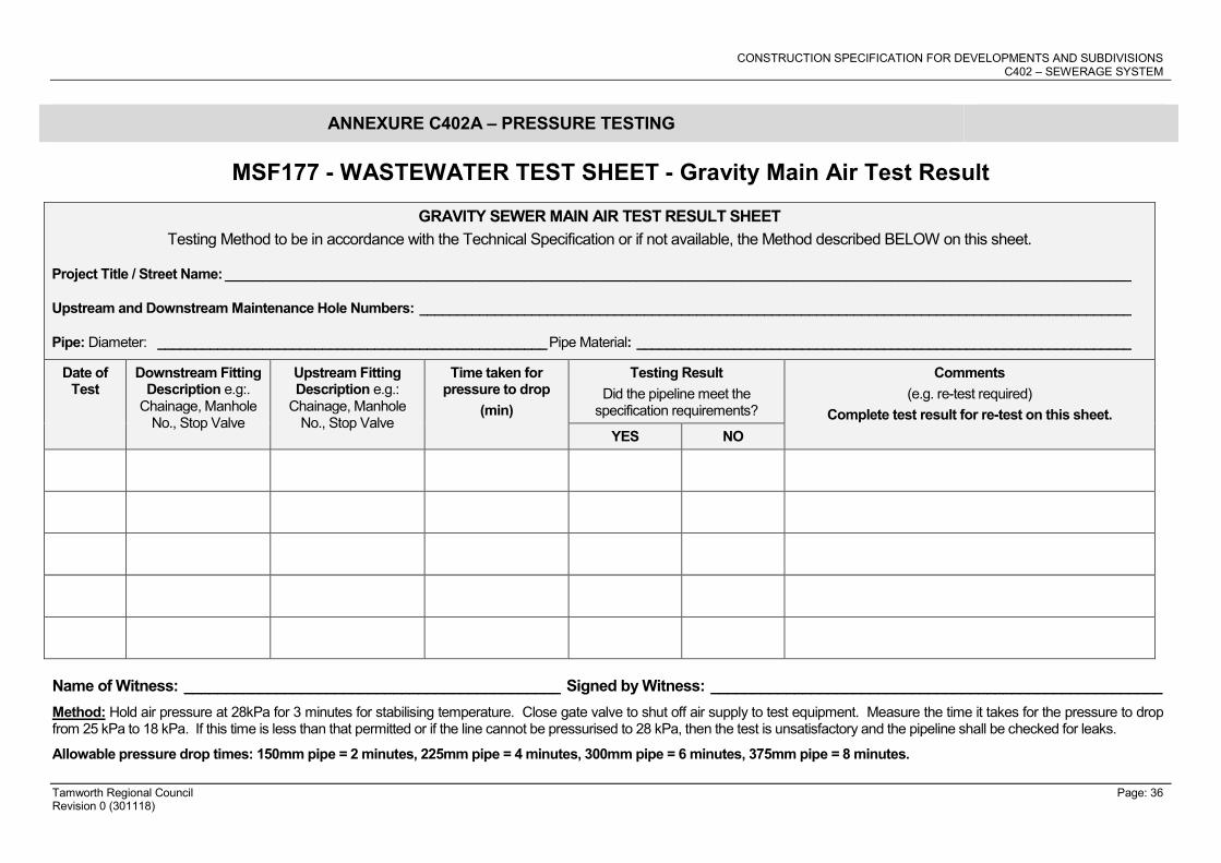
CONSTRUCTION SPECIFICATION FOR DEVELOPMENTS AND SUBDIVISIONS C402 – SEWERAGE SYSTEM
Tamworth Regional Council Page: 36 Revision 0 (301118)
ANNEXURE C402A – PRESSURE TESTING
MSF177 - WASTEWATER TEST SHEET - Gravity Main Air Test Result
GRAVITY SEWER MAIN AIR TEST RESULT SHEET
Testing Method to be in accordance with the Technical Specification or if not available, the Method described BELOW on this sheet.
Project Title / Street Name: _________________________________________________________________________________________________________________________
Upstream and Downstream Maintenance Hole Numbers: _______________________________________________________________________________________________
Pipe: Diameter: ____________________________________________________ Pipe Material: __________________________________________________________________
Date of Test
Downstream Fitting Description e.g:.
Chainage, Manhole No., Stop Valve
Upstream Fitting Description e.g.:
Chainage, Manhole No., Stop Valve
Time taken for pressure to drop
(min)
Testing Result
Did the pipeline meet the specification requirements?
Comments
(e.g. re-test required)
Complete test result for re-test on this sheet.
YES NO
Name of Witness: _____________________________________________ Signed by Witness: ______________________________________________________
Method: Hold air pressure at 28kPa for 3 minutes for stabilising temperature. Close gate valve to shut off air supply to test equipment. Measure the time it takes for the pressure to drop from 25 kPa to 18 kPa. If this time is less than that permitted or if the line cannot be pressurised to 28 kPa, then the test is unsatisfactory and the pipeline shall be checked for leaks.
Allowable pressure drop times: 150mm pipe = 2 minutes, 225mm pipe = 4 minutes, 300mm pipe = 6 minutes, 375mm pipe = 8 minutes.

CONSTRUCTION SPECIFICATION FOR DEVELOPMENTS AND SUBDIVISIONS C402 – SEWERAGE SYSTEM
Tamworth Regional Council Page: 37 Revision 0 (301118)
MSF-179 - WASTEWATER TEST SHEET – Pipeline Ovality Test Result
PIPELINE OVALITY TEST RESULT SHEET
Testing Method to be in accordance with the Technical Specification
Project Title: ____________________________________________________________________________________________________________________________________
Line No / Pipeline Description (Dia./ Pipe Material): _____________________________________________________________________________________________________
Date Downstream Fitting Description eg. Chainage,
Manhole No.
Upstream Fitting Description eg.
Chainage, Manhole No.
Testing Result – Did the pipeline meet the specification requirements?
Comments
(e.g. re-test required)
Complete test result for re-test on this sheet. YES NO
Name of Witness: _____________________________________________ Signed by Witness: ______________________________________________________