C4000 Select - Moxley Electronics Corp. - Home · 5.2.2 Mounting with side bracket ... 12.5 C4000...
84
OPERATING INSTRUCTIONS C4000 Select Safety Light Curtain GB
Transcript of C4000 Select - Moxley Electronics Corp. - Home · 5.2.2 Mounting with side bracket ... 12.5 C4000...
O P E R A T I N G I N S T R U C T I O N S
C4000 Select
Safety Light Curtain
GB

Operating Instructions
C4000 Select
2 © SICK AG • Industrial Safety Systems • Germany • All rights reserved 8012247/RI61/2007-11-30
This document is protected by the law of copyright, whereby all rights established therein remain with the com-pany SICK AG. Reproduction of this document or parts of this document is only permissible within the limits of thelegal determination of Copyright Law. Alteration or abridgement of the document is not permitted without theexplicit written approval of the company SICK AG.

Operating Instructions
C4000 Select
8012247/RI61/2007-11-30 © SICK AG • Industrial Safety Systems • Germany • All rights reserved 3
List of contents
List of contents1 About this document.........................................................................................................6
1.1 Function of this document....................................................................................61.2 Target group ..........................................................................................................61.3 Scope .....................................................................................................................61.4 Depth of information.............................................................................................61.5 Abbreviations.........................................................................................................71.6 Symbols used ........................................................................................................7
2 On safety.............................................................................................................................92.1 Qualified safety personnel....................................................................................92.2 Applications of the device.....................................................................................92.3 Correct use ..........................................................................................................102.4 General safety notes and protective measures ................................................102.5 Protection of the environment............................................................................11
3 Product description.........................................................................................................123.1 Special features ..................................................................................................123.2 Operating principle of the device .......................................................................12
3.2.1 C4000 Select components...............................................................123.2.2 The light curtain principle .................................................................133.2.3 Device variants..................................................................................133.2.4 Standalone and cascaded systems .................................................13
3.3 Examples of range of use ...................................................................................173.4 Status indicators and C4000 Select message center ......................................18
3.4.1 Message center of the C4000 Select sender unit ..........................183.4.2 Message center of the C4000 Select receiver unit ........................193.4.3 Optional integrated LED....................................................................20
4 Configuration ...................................................................................................................214.1 Extended I/O........................................................................................................224.2 Beam coding........................................................................................................234.3 Scanning range ...................................................................................................254.4 Floating blanking.................................................................................................27
5 Installation and mounting ..............................................................................................295.1 Determining the minimum safety distance .......................................................29
5.1.1 Minimum safety distance to the hazardous area............................295.1.2 Hazard approach...............................................................................305.1.3 Minimum safety distance according to ANSI/CSA standards
and OSHA regulations.......................................................................315.1.4 Minimum safety distance according to EN 999 and EN 294.........325.1.5 Minimum distance to reflective surfaces ........................................33
5.2 Steps for mounting the device ...........................................................................345.2.1 Mounting with swivel mount bracket ...............................................365.2.2 Mounting with side bracket ..............................................................385.2.3 Mounting with rigid mounting bracket .............................................40
5.3 Laser alignment ..................................................................................................41

Operating Instructions
C4000 Select
4 © SICK AG • Industrial Safety Systems • Germany • All rights reserved 8012247/RI61/2007-11-30
List of contents
6 Electrical installation .....................................................................................................436.1 Bottom end cap with system connection M12�×5 male ..................................446.2 Bottom end cap with system connection M12�×5 male and extended
I/O connection M12�×5 female .........................................................................446.3 Top end cap with extended I/O M12�×5 female connection ...........................46
7 Commissioning................................................................................................................477.1 Display sequence during power-up....................................................................477.2 Aligning sender and receiver..............................................................................477.3 Test notes............................................................................................................48
7.3.1 Tests before the first commissioning ..............................................487.3.2 Regular inspection of the protective device by qualified
safety personnel ...............................................................................487.3.3 Daily functional checks of the protective device ............................49
8 Configuration...................................................................................................................50
9 Care and maintenance ...................................................................................................51
10 Fault diagnosis................................................................................................................5210.1 What to do in case of faults ...............................................................................5210.2 SICK Support.......................................................................................................5210.3 Error displays of the diagnostics LEDs ..............................................................5210.4 Error displays of the 7segment display ............................................................54
11 Technical specifications ................................................................................................5511.1 Data sheet...........................................................................................................5511.2 Response time....................................................................................................58
11.2.1 Calculating the host/standalone response time ............................5811.2.2 Calculating the guest 1 response time............................................5911.2.3 Calculating the guest 2 response time............................................6011.2.4 Response time calculation examples..............................................60
11.3 Table of weights..................................................................................................6311.3.1 C4000 Select ....................................................................................6311.3.2 Deflector mirrors PNS75 and PNS125............................................63
11.4 Dimensional drawings ........................................................................................6411.4.1 C4000 Select receiver (all variants) ................................................6411.4.2 C4000 Select sender (all variants)..................................................6511.4.3 Swivel mount bracket .......................................................................6611.4.4 Side mount bracket ..........................................................................6611.4.5 Standard L-type mounting brackets ................................................6711.4.6 Deflector mirror PNS75....................................................................6811.4.7 Deflector mirror PNS125..................................................................69
Operating Instructions
C4000 Select
8012247/RI61/2007-11-30 © SICK AG • Industrial Safety Systems • Germany • All rights reserved 5
List of contents
12 Ordering information.......................................................................................................7012.1 Delivery ................................................................................................................7012.2 C4000 Select without extension connection.....................................................7012.3 C4000 Select with integrated LED status indicator..........................................7112.4 C4000 Select with top end cap extension connection .....................................7112.5 C4000 Select with bottom end cap system and extension connections.........7212.6 C4000 Select with bottom end cap system/extension connections and
integrated LED status indicator..........................................................................7212.7 C4000 Select with bottom extension connection (receiver only).....................7312.8 C4000 Select with bottom extension connection and integrated LED
status indicator (receiver only) ...........................................................................7312.9 Additional front screen (weld spark guard) .......................................................7412.10 Deflector mirror ...................................................................................................74
12.10.1 Deflector mirror PNS75 for protective field width 0 … 12 m(total)..................................................................................................74
12.10.2 Deflector mirror PNS125 for protective field width4 … 18.5 m (total) .............................................................................74
12.11 Accessories..........................................................................................................75
13 Annex ................................................................................................................................7713.1 EC declaration of conformity ..............................................................................7713.2 Checklist for the manufacturer ..........................................................................7813.3 List of tables........................................................................................................7913.4 List of illustrations...............................................................................................80
Chapter 1 Operating Instructions
C4000 Select
6 © SICK AG • Industrial Safety Systems • Germany • All rights reserved 8012247/RI61/2007-11-30
About this document
1 About this documentPlease read this chapter carefully before working with this documentation and the C4000Select.
1.1 Function of this documentThese operating instructions are designed to address the technical personnel of themachine manufacturer or the machine operator in regards to safe mounting, installation,configuration, electrical installation, commissioning, operation and maintenance of theC4000 Select safety light curtain.
These operating instructions do not provide instructions for operating machines on whichthe safety light curtain is, or will be, integrated. Information on this is to be found in theappropriate operating instructions of the machine.
1.2 Target groupThese operating instructions are addressed to planning engineers, developers and theoperators of plants and systems which are to be protected by one or several C4000 Selectsafety light curtains. It also addresses persons who integrate the C4000 Select into a ma-chine, initialize its use, or who are in charge of servicing and maintaining the device.
1.3 ScopeThese operating instructions apply to the C4000 Select safety light curtain with one of thefollowing entries on the type label in the field Operating Instructions:
� 8012198
� 8012198 / RI61
This document is part of SICK part number 8012198 (operating instructions “C4000Select” in all available languages).
1.4 Depth of informationThese operating instructions contain information on:
� installation and mounting
� electrical installation
� commissioning and configuration
� care and maintenance
� fault, error diagnosis andtroubleshooting
� part numbers
� conformity and approval
of the C4000 Select safety light curtain.
Planning and using protective devices such as the C4000 Select also require specific tech-nical skills which are not detailed in this documentation.
When operating the C4000 Select, the national, local and statutory rules and regulationsmust be observed.
General information on health and safety at work and accident prevention using opto-elec-tronic protective devices can be found in the brochure “Safe Machines with opto-electronicprotective devices” from SICK.
Note

Operating Instructions Chapter 1
C4000 Select
8012247/RI61/2007-11-30 © SICK AG • Industrial Safety Systems • Germany • All rights reserved 7
About this document
We also refer you to the SICK homepage on the Internet at
www.sick.com
Here you will find information on:
� sample applications
� a list of frequently asked questions about the C4000 Select
� these operating instructions in different languages for viewing and printing
� certificates on the prototype test, the EC declaration of conformity and other documents
1.5 AbbreviationsElectro-sensitive protective equipment (e.g. C4000 Select)
Output signal switching device
The probability of failure per hour in accordance with the functional safety testingrequirements outlined in IEC 61�508
Performance level in accordance with EN ISO 13�8491:2006
Safety integrity level in accordance with IEC 61�508/IEC 62�061
1.6 Symbols usedRecommendations are designed to give you some assistance in your decision-makingprocess with respect to a certain function or a technical measure.
Refer to notes for special features of the device.
Display indicators show the status of the 7segment display of sender or receiver:� Constant indication of characters, e.g. 2When using an inverted mounting of the C4000 Select, you must take into account thatthe information presented by the 7-segment display will also be inverted.
LED symbols describe the state of a diagnostics LED. Examples:� Red The red LED is illuminated constantly.� Red The red LED is flashing.� Off The LED is off.
Instructions for taking action are shown by an arrow. Read carefully and follow the instruc-tions for action.
Warning!
A warning indicates an actual or potential risk or health hazard. They are designed to helpyou to prevent accidents.
Read carefully and follow the warnings!
Sender and receiver
In drawings and diagrams, the symbol � denotes the sender and the symbol � denotesthe receiver.
Note
ESPE
OSSD
PFH
PL
SIL
Recommendation
Note
�
� Red, � Red, � Off
� Take action …
WARNING
��

Chapter 1 Operating Instructions
C4000 Select
8 © SICK AG • Industrial Safety Systems • Germany • All rights reserved 8012247/RI61/2007-11-30
About this document
The term “dangerous state”
The dangerous state (standard term) of the machine is always shown in the drawings anddiagrams of this document as the movement of a machine part. In practical operation,there may be a number of different dangerous states:
� machine movements
� electrical conductors
� visible or invisible radiation
� a combination of several risks and hazards

Operating Instructions Chapter 2
C4000 Select
8012247/RI61/2007-11-30 © SICK AG • Industrial Safety Systems • Germany • All rights reserved 9
On safety
2 On safetyThis chapter deals with your own safety and the safety of the equipment operators.
� Please read this chapter carefully before working with the C4000 Select or with themachine protected by the C4000 Select.
2.1 Qualified safety personnelThe C4000 Select safety light curtain must be installed, connected, commissioned andserviced only by qualified safety personnel. Qualified safety personnel are defined aspersons who …
� due to their specialist training and experience have adequate knowledge of the power-driven equipment to be checked
and
� who have been instructed by the responsible machine operator in the operation of themachine and the current valid safety guidelines
and
� are sufficiently familiar with the applicable official health and safety regulations,directives and generally recognized engineering practice (e.g. DIN standards, VDEstipulations, engineering regulations from other EC member states) that they canassess the work safety aspects of the power-driven equipment
and
� who have access to these operating instructions and who have read and understoodthem.
As a rule these are qualified safety personnel from the ESPE manufacturer or also thosepersons who have been appropriately trained at the ESPE manufacturer, are primarilyinvolved in checking ESPE and are allocated the task by the organization operating theESPE.
2.2 Applications of the deviceThe C4000 Select safety light curtain is an electro-sensitive protective equipment (ESPE)rated to:
� type 4 in accordance with IEC 61�4961 and 2
� SIL 3 in accordance with IEC 61�508 and IEC 62�061
� category 4 in accordance with EN 9541:1997
� performance level “e” in accordance with EN ISO 13�8491:2006
The physical resolution of the C4000 Select is 30 mm with a maximum protective fieldwidth of up to 21 m and available protective field heights from 300 up to 1800 mm. Con-figurable parameters are set using DIP switches.
The device is suitable for:
� hazardous point protection (hand protection)
� hazardous area protection
� access protection

Chapter 2 Operating Instructions
C4000 Select
10 © SICK AG • Industrial Safety Systems • Germany • All rights reserved 8012247/RI61/2007-11-30
On safety
Access to the hazardous point must be allowed only through the protective field. Theplant/system is not allowed to start as long as personnel are within the hazardous area.Refer to chapter 3.3 “Examples of range of use” on page 17 for an illustration of theprotection modes.
Only use the safety light curtain as an indirect protective measure!
An opto-electronic protective device provides indirect protection, e.g., by switching off thepower at the source of the hazard. It cannot provide protection from parts thrown out, norfrom emitted radiation. Transparent objects are not detected.
Depending on the application, mechanical protection devices may be required in additionto the safety light curtain.
The C4000 Select safety light curtain operates as a standalone system, comprising a sen-der and receiver, or in combination with other extended C4000 Select systems, SICK S300or S3000 safety laser scanners. This means that the protective field can be adapted tosuit individual safety requirements.
2.3 Correct useThe C4000 Select safety light curtain must be used only as defined in section 2.2 “Applica-tions of the device”. It must be used only by qualified safety personnel and only on themachine where it has been installed and initialized by qualified safety personnel inaccordance with these operating instructions.
If the device is used for any other purposes or modified in any way—also during mountingand installation—any warranty claim against SICK AG and its subsidiary companies shallbecome void.
2.4 General safety notes and protective measures
Safety notes
Please observe the following procedures in order to ensure the correct and safe use of thesafety light curtain C4000 Select.
� The national/international rules and regulations apply to the installation, use andperiodic technical inspections of the safety light curtain, in particular:
– Machinery Directive 98/37/EEC– Equipment Usage Directive 89/655/EEC– the work safety regulations/safety rules– other relevant health and safety regulationsManufacturers and operators of the machine with which the safety light curtain is usedare responsible for obtaining and observing all applicable safety regulations and rules.
� The notices, in particular the test regulations (see “Test notes” on page 48) of theseoperating instructions (e.g. on use, mounting, installation or integration into the existingmachine controller) must be observed.
� Changes to the configuration of the devices can degrade the protective function. Afterevery change to the configuration you must therefore reverify and validate the effective-ness of the protective device (e.g. C4000 Select).
The person who makes the change is also responsible for the correct protective functionof the device.
WARNING
Note
WARNING

Operating Instructions Chapter 2
C4000 Select
8012247/RI61/2007-11-30 © SICK AG • Industrial Safety Systems • Germany • All rights reserved 11
On safety
� The tests must be carried out by authorized qualified safety personnel and must be re-corded and documented to ensure that the tests can be reconstructed and retraced atany time.
� The operating instructions must be made available to the operator of the machinewhere the C4000 Select safety light curtain is installed. The machine operator is to beinstructed in the use of the device by qualified safety personnel and must be instructedto read the operating instructions.
� The external voltage supply of the device must be capable of buffering brief mains vol-tage failures of 20 ms as specified in EN 60�2041. Suitable power supplies are availa-ble as accessories from SICK (i.e. model PS50W24V, SICK part number 7028789 orPS95W24V, SICK part number 7028790).
2.5 Protection of the environmentThe C4000 Select safety light curtain has been designed to minimize environmentalimpact. It uses only a minimum of power and natural resources.
At work, always act in an environmentally responsible manner. For this reason please notethe following information on disposal.
Disposal
� Always dispose of unserviceable or irreparable devices in compliance withlocal/national rules and regulations with respect to waste disposal.
� We would be pleased to be of assistance on the disposal of this device. Contact yourlocal SICK representative.
� The disposal of Instapak® foam inserts included in the C4000 Select packaging is com-pletely compatible with waste-to-energy facilities. Instapak® foam has high energy con-tent similar to that of coal. Instapak® foam can actually be used to aid in the process-ing of other less combustible materials. The process leaves less than one-percent ashand is completely free of any heavy metals. Instapak® foam also has a recycling pro-gram available to help companies meet their recycling needs. Instapak® foam may bereturned to any one of more than twenty-five worldwide locations. Refer on the internetto http://www.instapak.com/ for additional information.
Notes

Chapter 3 Operating Instructions
C4000 Select
12 © SICK AG • Industrial Safety Systems • Germany • All rights reserved 8012247/RI61/2007-11-30
Product description
3 Product descriptionThis chapter provides information on the special features and properties of the C4000Select safety light curtain. It describes the construction and the operating principle of thedevice, in particular the different operating modes.
� Please read this chapter before mounting, installing and commissioning the device.
3.1 Special featuresThe C4000 Select supports the following special features:
� integrated laser and alignment bar graph
� configuration via DIP switches
� simple diagnostic codes
� an optional LED status indicator
� cascading additional C4000 Select system(s) or a single S300/S3000 safety laserscanner
� 2 beam codes possible in addition to non-coded operation
� status display with 7segment display
� one or two beam floating blanking
3.2 Operating principle of the device
3.2.1 C4000 Select components
Please refer to chapter 11 “Technical specifications” on page 55 for the data sheet.Please refer to pages 64ff. for the dimensional drawings.
Fig. 1: Components of theC4000 Select
Host without extensionconnection or — in caseguest 1 connected — withextension connection
Optional: 1. Guest systemwithout extensionconnection or — in caseguest 2 connected — withextension connection
Optional: 2. Guest systemwith or without extensionconnection

Operating Instructions Chapter 3
C4000 Select
8012247/RI61/2007-11-30 © SICK AG • Industrial Safety Systems • Germany • All rights reserved 13
Product description
3.2.2 The light curtain principle
The C4000 Select safety light curtain consists of a sender and a receiver (Fig. 1). Betweenthese two units is the protective field, defined by a protective field height and a protectivefield width.
The construction height determines the height of the protective field of the appropriatesystem. For the exact protective field height, please see Tab. 40ff. in chapter 11.4“Dimensional drawings” on page 64.
The width of the protective field is derived from the dimension of the light path betweensender and receiver and must satisfy the specification requirements for the protective field(see “Technical specifications” on page 55).
Sender and receiver automatically synchronize themselves optically. An electrical connec-tion between both components is not required.
The C4000 Select is modular in construction. All optical and electronic components andassemblies are housed in a slim and torsionally rigid housing.
3.2.3 Device variants
The C4000 Select sender and receiver devices support several end cap configurations.You must decide which end cap is best suited for your application at time of order place-ment. The bottom end cap supports the system connection and optional extended I/Ofunctionality. Three top end cap options are available: cover only, with an optionalintegrated LED or with an optional extended I/O connection.
There are several variants of the C4000 Select:
� without any extension connection (no extended I/O capability)
� without any extension connection (no extended I/O capability) with integrated LED onthe top end cap of the receiver unit
� with extension connection (supports cascading) located on the bottom end cap with thesystem connection
� with extension connection (supports cascading) located on the top end cap with a sepa-rate bottom end cap having the system connection
� with extension connection (supports cascading) located on the bottom end cap with thesystem connection with integrated LED on the top end cap of the receiver unit
3.2.4 Standalone and cascaded systems
The C4000 Select allows you to coordinate multiple protective devices (e.g. additionalC4000 Select devices or SICK S300/S3000 safety laser scanner) in a single safetysystem.
A maximum of three C4000 Select devices can be connected in series as a “cascade”. Thefollowing configurations are possible:
� standalone operation of a single C4000 Select system
� cascade of a host C4000 Select with a guest C4000 Select
� cascade of a host C4000 Select with two guest C4000 Select devices
� cascade of a host C4000 Select with a SICK S300/S3000 safety laser scanner
Cascaded devices are connected using the extended I/O connection. The extended I/Oconnection may be located either beside the system connection (extended I/O connectionon the bottom end cap) or separate from the system connection (extended I/O connectionon the top end cap).
Chapter 3 Operating Instructions
C4000 Select
14 © SICK AG • Industrial Safety Systems • Germany • All rights reserved 8012247/RI61/2007-11-30
Product description
The benefits of cascading include:
� no additional external circuitry required making connection of additional protectivedevices easy to implement
� the protective field height may differ among the individual C4000 Select devices
� a combination of hazardous point (i.e. C4000 Select) and area protection devices (e.g.SICK S300/S3000 safety laser scanners) can be realized in a single safety system.
The following sections describe the different configurations supported by the C4000Select. For ease of understanding, only the receiver units have been shown in subsequentfigures.
Ensure that you set the Extended I/O DIP switch correctly for your application!
When cascading additional protective devices to the C4000 Select, you must ensure thatthe Extended I/O DIP switch has been set to Enabled. Failure to enable the Extended I/Ofunction in cascaded applications will expose personnel to risk of the associated hazard!Please refer to chapter 4 “Configuration” on page 21 for additional details regardingextended I/O DIP switch settings and functionality.
Standalone operation
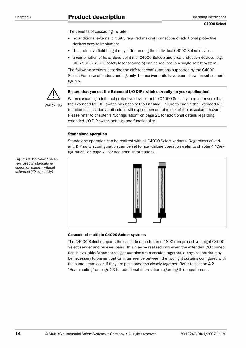
Standalone operation can be realized with all C4000 Select variants. Regardless of vari-ant, DIP switch configuration can be set for standalone operation (refer to chapter 4 “Con-figuration” on page 21 for additional information).
Cascade of multiple C4000 Select systems
The C4000 Select supports the cascade of up to three 1800 mm protective height C4000Select sender and receiver pairs. This may be realized only when the extended I/O connec-tion is available. When three light curtains are cascaded together, a physical barrier maybe necessary to prevent optical interference between the two light curtains configured withthe same beam code if they are positioned too closely together. Refer to section 4.2“Beam coding” on page 23 for additional information regarding this requirement.
WARNING
Fig. 2: C4000 Select recei-vers used in standaloneoperation (shown withoutextended I/O capability)

Operating Instructions Chapter 3
C4000 Select
8012247/RI61/2007-11-30 © SICK AG • Industrial Safety Systems • Germany • All rights reserved 15
Product description
There are two methods of implementing C4000 Select cascades. The first method utilizesan extended I/O connection located on the top end cap for the first C4000 Select (host)and the second C4000 Select (guest 1). The third C4000 Select (guest 2) utilizes a systemconnection only.
Alternatively, the second method of implementing cascaded C4000 Select devices uses anextended I/O connection that is located on the same end cap as the system connection.
Sender units cannot be physically connected to receiver units when cascading C4000Select devices. Always physically connect sender units together when cascading. Alwaysphyscially connect receiver units together when cascading C4000 Select devices.
Fig. 3: C4000 Select recei-vers used in cascade withextension connection (on topend cap)
Fig. 4: C4000 Select recei-vers used in cascade withextension connection (onsame end cap as systemconnection)
Note
Guest 1
Host Guest 2
Guest 1Host Guest 2

Chapter 3 Operating Instructions
C4000 Select
16 © SICK AG • Industrial Safety Systems • Germany • All rights reserved 8012247/RI61/2007-11-30
Product description
Cascade of C4000 Select and SICK S300/S3000 safety laser scanner
The C4000 Select supports the cascade of a single SICK S300 or S3000 safety laser scan-ner. Connection of the S300 or S3000 occurs on the extended I/O connection to provideboth power and connection of safety relevant signals (i.e. safety outputs from the safetyscanner). The extended I/O connection may be located on either the top end cap or withthe system connection on the bottom end cap of the C4000 Select.
Fig. 5: C4000 Select receiverwith extended I/O connection(shown on top end cap andwith system connection) usedto cascade a SICK S3000safety laser scanner

Operating Instructions Chapter 3
C4000 Select
8012247/RI61/2007-11-30 © SICK AG • Industrial Safety Systems • Germany • All rights reserved 17
Product description
3.3 Examples of range of use
The C4000 Select safety light curtain operates correctly as a protective device only if thefollowing conditions are met:
� The control of the machine must be electrical.
� The dangerous state of the machine must be transferable at any time into a safe state.
� Sender and receiver unit must be mounted so that objects penetrating the hazardousarea are safely identified by the C4000 Select.
� An external reset/restart function (e.g. button) must be fitted outside the hazardousarea such that it cannot be operated by a person working inside the hazardous area.When operating the reset button, the operator must have full visual command of thehazardous area.
� The statutory and local rules and regulations must be observed when installing andusing the device.
Fig. 6: Hazardous point pro-tection using a C4000 Selectsafety light curtain(left)
Fig. 7: Hazardous area pro-tection using a C4000 Selectsafety light curtain(right)
Fig. 8: Access protectionusing a C4000 Select safetylight curtain cascaded withan S3000 safety laserscanner

Chapter 3 Operating Instructions
C4000 Select
18 © SICK AG • Industrial Safety Systems • Germany • All rights reserved 8012247/RI61/2007-11-30
Product description
3.4 Status indicators and C4000 Select message centerThe C4000 Select provides simple operational status information using LED indicators anda 7segment display.
3.4.1 Message center of the C4000 Select sender unit
The message center for the C4000 Select sender unit has two LEDs that provide operatio-nal status as shown in the figure below:
LED Name Display Meaning
� Yellow Supply voltage OKPOWER
� Off Check the power to the sender unit
� Red The sender unit has detected an internal error. Replace senderunit.REPLACE
� Off Internal self-test completed successfully or power is off.
Fig. 9: Message center forC4000 Select sender unit
Tab. 1: C4000 Select LEDindication on sender
Laser alignment
Operating Instructions Chapter 3
C4000 Select
8012247/RI61/2007-11-30 © SICK AG • Industrial Safety Systems • Germany • All rights reserved 19
Product description
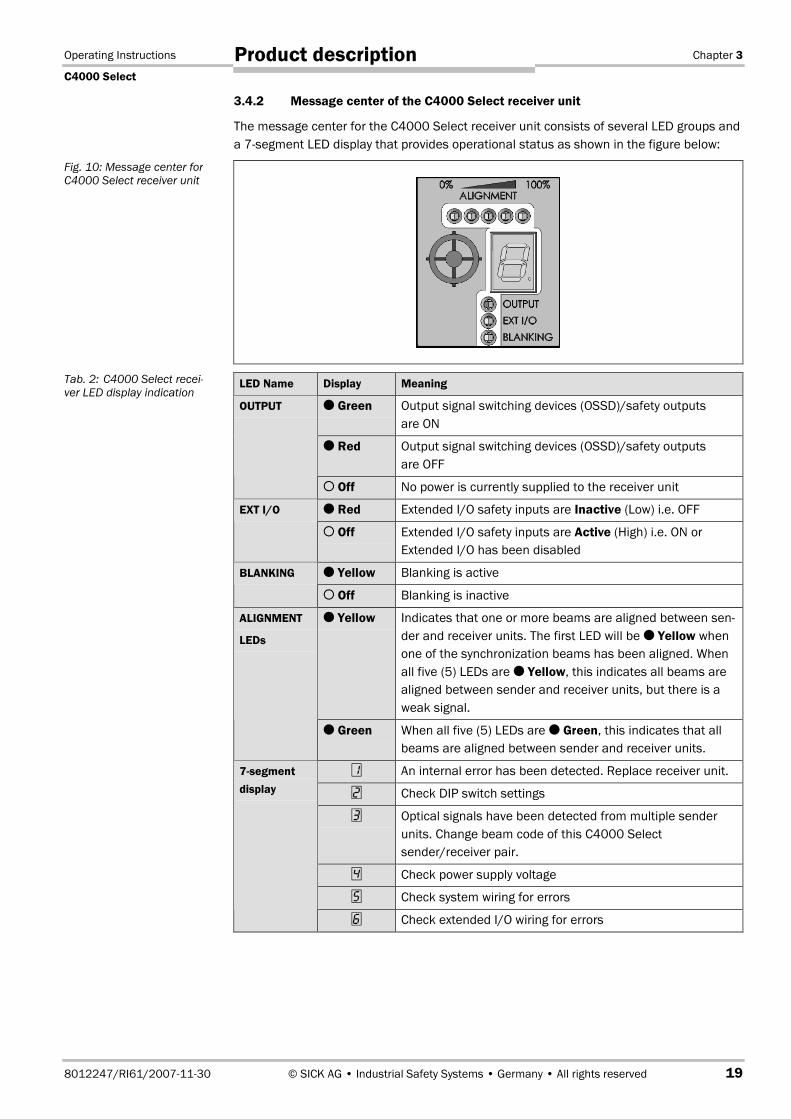
3.4.2 Message center of the C4000 Select receiver unit
The message center for the C4000 Select receiver unit consists of several LED groups anda 7segment LED display that provides operational status as shown in the figure below:
LED Name Display Meaning
� Green Output signal switching devices (OSSD)/safety outputsare ON
� Red Output signal switching devices (OSSD)/safety outputsare OFF
OUTPUT
� Off No power is currently supplied to the receiver unit
� Red Extended I/O safety inputs are Inactive (Low) i.e. OFFEXT I/O
� Off Extended I/O safety inputs are Active (High) i.e. ON orExtended I/O has been disabled
� Yellow Blanking is activeBLANKING
� Off Blanking is inactive
� Yellow Indicates that one or more beams are aligned between sen-der and receiver units. The first LED will be � Yellow whenone of the synchronization beams has been aligned. Whenall five (5) LEDs are � Yellow, this indicates all beams arealigned between sender and receiver units, but there is aweak signal.
ALIGNMENT
LEDs
� Green When all five (5) LEDs are � Green, this indicates that allbeams are aligned between sender and receiver units.
� An internal error has been detected. Replace receiver unit.
� Check DIP switch settings
� Optical signals have been detected from multiple senderunits. Change beam code of this C4000 Selectsender/receiver pair.
� Check power supply voltage
� Check system wiring for errors
7segmentdisplay
� Check extended I/O wiring for errors
Fig. 10: Message center forC4000 Select receiver unit
Tab. 2: C4000 Select recei-ver LED display indication

Chapter 3 Operating Instructions
C4000 Select
20 © SICK AG • Industrial Safety Systems • Germany • All rights reserved 8012247/RI61/2007-11-30
Product description
3.4.3 Optional integrated LED
When the receiver unit includes the optional integrated LED, the following LED states aredefined:
Integrated LED Meaning
� Red Output signal switching devices (OSSD)/safety outputs are OFF
� Green Output signal switching devices (OSSD)/safety outputs are ON
� Off No power is currently supplied to the receiver unit
Tab. 3: C4000 Select integra-ted LED display indication

Operating Instructions Chapter 4
C4000 Select
8012247/RI61/2007-11-30 © SICK AG • Industrial Safety Systems • Germany • All rights reserved 21
Configuration
4 ConfigurationThe C4000 Select supports several advanced functions which are configured using DIPswitches. Included in these advanced functions are beam coding, extended I/O capabilityand floating blanking. The DIP switches used for configuration are located under theplastic cover in the system connection end cap.
You must ensure electrostatic discharge does not occur when handling the C4000Select!
Before handling the C4000 Select, you must ensure that any electrostatic charge is dis-charged. An electrostatic discharge that occurs on the C4000 Select may cause damageto the electronic boards.
The following figure and table describe the C4000 Select sender unit DIP switch settings:
Beam code 1 Beam code 2 Description
OFF OFF No beam coding (uncoded)
ON OFF Beam code 1 enabled
OFF ON Beam code 2 enabled
ON ON No beam coding (uncoded)
Additional information regarding the scanning range can be found in section 4.2 “Beamcoding” on page 23.
The following figure and table describe the C4000 Select receiver unit DIP switch settings:
High range select Description
OFF Scanning range set to low range (0…7.5 m)
ON Scanning range set to high range (5…21 m)
Additional information regarding the scanning range can be found in section 4.3 “Scanningrange” on page 25.
WARNING
Fig. 11: C4000 Select senderunit DIP switch
Tab. 4: C4000 Select senderunit DIP switch settings
Fig. 12: C4000 Select recei-ver unit DIP switches
Tab. 5: C4000 Select recei-ver unit DIP switch settingsfor high range
1 = Beam code 1 select2 = Beam code 2 select
1 = High range select2 = Extended I/O enable
1 = Beam code 1 select2 = Beam code 2 select3 = Floating blanking enable4 = One beam floating blanking select5 = Two beam floating blanking select
ON position
OFF position

Chapter 4 Operating Instructions
C4000 Select
22 © SICK AG • Industrial Safety Systems • Germany • All rights reserved 8012247/RI61/2007-11-30
Configuration
Extended I/O enable Description
OFF Extended I/O functions are disabled
ON Extended I/O functions are enabled
Additional information regarding the scanning range can be found in section 4.1“Extended I/O” on page 22.
Beam code 1 Beam code 2 Description
OFF OFF No beam coding (uncoded)
ON OFF Beam code 1 enabled
OFF ON Beam code 2 enabled
ON ON No beam coding (uncoded)
Additional information regarding the scanning range can be found in section 4.2 “Beamcoding” on page 23.
Floatingblankingenable
One beamFB select
Two beamFB select
Description
OFF OFF OFF Floating blanking is disabled
ON ON OFF Floating blanking is enabled for 1 beam blanking
ON OFF ON Floating blanking is enabled for 2 beam blanking
All other configurations Invalid configuration will result in a fault condition
Additional information regarding the scanning range can be found in section 4.4 “Floatingblanking” on page 27.
4.1 Extended I/OEnabling the C4000 Select extended I/O functionality allows the connection (i.e. cascade)of additional C4000 Select or SICK S300/S3000 safety laser scanners with the C4000Select. Refer to section 3.2.4 “Standalone and cascaded systems” on page 13 foradditional details regarding C4000 Select cascading options.
When additional devices are cascaded with the C4000 Select, the safety outputs (OSSDs)of the host C4000 Select represent the logical value of all devices in the cascade.
Extended I/ODIP switchsetting
Extended I/Osafe input 1
Extended I/Osafe input 2
C4000 Selectprotective field
C4000 Selectsafety outputs(OSSDs)
01) 0 0
0 12) 0
1 0 0Enabled
1 1 1
0 0 1
0 1 0
1 0 0Disabled
1 1
Aligned andunblocked
0
1) E.g. inactive (low); red.2) E.g. active (high); green.
Tab. 6: C4000 Select recei-ver unit DIP switch settingsfor extended I/O enable
Tab. 7: C4000 Select recei-ver unit DIP switch settingsfor beam coding
Tab. 8: C4000 Select recei-ver unit DIP switch settingsfor floating blanking
Tab. 9: C4000 Select exten-ded I/O system output evalu-ation of the C4000 Selecthost device

Operating Instructions Chapter 4
C4000 Select
8012247/RI61/2007-11-30 © SICK AG • Industrial Safety Systems • Germany • All rights reserved 23
Configuration
When the extended I/O safety inputs are not at their expected state (e.g. both inputsshould be Active (High) or Inactive (Low)), they are considered “discrepant”. The inputsmust reach an equivalent value before the internal discrepancy timer expires. Failure toreach an equivalent value before the discrepancy time expires will cause a lock-outcondition to occur.
Electrical-mechanical devices (e.g. emergency stop buttons or safety interlock switches)must not be connected to the extended I/O.
You must ensure that the Extended I/O DIP switch setting satisfies your safetyapplication requirements!
When cascading one or more devices with the C4000 Select, you must ensure that the ex-tended I/O DIP switch setting(s) for extended I/O is enabled as required for your applica-tion. You must also validate that the C4000 Select and all cascaded protective devicesperform in accordance with your risk assessment, risk reduction strategy as well as appli-cable local, regional and national regulatory requirements.
You must ensure that protective device inputs attached to the inputs of the extendedI/O connection can be read safely!
The inputs (IN1, IN2) of an extended I/O connnection enable the 24 V DC PNP-semicon-ductor safety outputs from a self-monitoring sensor (e.g. another C4000 Select or anS300/S3000 safety laser scanner) to be read safely. The sensor connected to the inputsof the extended I/O connection (e.g. guest C4000 Select or S3000 safety laser scanner)must …
� be self-monitoring and detect any error conditions that may occur with its output signalswitching devices (OSSDs) using test signals. The host C4000 Select filters these testsignals out.
� execute a safe shutdown of the switching outputs when any error is detected.
Integrated safety mechanisms ensure detection of possible errors on safety capable inputsfor:
� Internal errors on safety capable inputs which prevent the inputs from returning to thesafe state. An internal error on a safety capable input is a failure of the C4000 Selectelectrical input circuitry.
� Discrepancy of the dual-channel input evaluation
Additional measures must be made to address any external errors that cannot be moni-tored internally by the C4000 Select. In addition, you must exclude any external errors thatcould occur due to selected user configuration parameters.
4.2 Beam codingIf several safety light curtains operate in close proximity to each other, the sender beamsof one system may optically interfere or even align itself with the receiver of another sys-tem. With code 1 or 2 activated, the receiver can distinguish the beams designated for itfrom other beams. The following settings are available: non-coded, code 1 and code 2.
Use different beam codings if the systems are mounted in close proximity!
Systems mounted in close proximity to each other must be operated with different beamcodings (code 1 or code 2). If this precaution is neglected, the system may be impaired inits protective function by the beams from the neighboring system and so change to theunsafe state. This would mean that the operator is at risk.
WARNING
WARNING

Chapter 4 Operating Instructions
C4000 Select
24 © SICK AG • Industrial Safety Systems • Germany • All rights reserved 8012247/RI61/2007-11-30
Configuration
� Beam coding increases the availability of the protected machine. Beam coding also en-hances the resistance to optical interference such as weld sparks.
� Using different beam coding settings will allow one C4000 series sender/receiver pairto be mounted in close proximity to another C4000 series sender/receiver pair withoutoptical interference.
� Beam coding will increase the response time of the system. This will also change therequired safety distance. Instructions can be found in chapter 5.1 “Determining theminimum safety distance” on page 29.
� In order for the C4000 Select system to operate, both the sender and correspondingreceiver of each C4000 Select system must have the same beam code configuration.
� After activating the system, the C4000 Select receiver will briefly display the coding.
7-segment display Description
� No beam coding
� Beam code 1 active
Beam code 2 active
To prevent the possibility of optical interference from C4000 Select devices that havebeen configured with the same beam codes (e.g. no coding, beam code 1 or beam code2), a minimum distance between the two systems must be implemented. The followingfigure provides information regarding the minimum distance “a” that must separate thetwo C4000 Select systems based on the distance D between the sender of system 1 andthe receiver of system 2.
Fig. 13: Schematic layout ofthe beam coding
Notes
Tab. 10: C4000 Select 7seg-ment display on power-up forbeam coding
Fig. 14: Minimum distancebetween C4000 Select sys-tems for systems with thesame beam code configura-tion
Code 1
Code 2
D
a
System 1
System 2

Operating Instructions Chapter 4
C4000 Select
8012247/RI61/2007-11-30 © SICK AG • Industrial Safety Systems • Germany • All rights reserved 25
Configuration
Refer to chapter 4 “Configuration” on page 21 for additional details on DIP switch settingrequirements for beam coding.
4.3 Scanning rangeScanning range defines the strength of the C4000 Select protective field beams in order toallow for longer distances between the C4000 Select sender and receiver devices.
Match the scanning range with the protective field width!
The scanning range of the system (host, guest 1 and guest 2) must be adapted to the pro-tective field width. If the scanning range is set to high range and the light curtains aremounted below the minimum scanning range value, the safety light curtain may not reliab-ly detect objects within the protective field. This would mean that the operator is at risk.
Two scanning ranges are selectable:
Physical resolution Selectable scanning ranges
0…7.5 m30 mm
5…21 m
7segment display Description
No symbol Low range (0…7.5 m) selected
High range (5…21 m) selected
� If the scanning range is set too low, the safety light curtain may not switch to green.
� Tab. 11 shows the guaranteed scanning ranges for the system.
� Deflector mirrors are available as accessories (see page 74f.). When used, deflectormirrors will reduce the effective scanning range based on the number used (seeTab. 13). When using deflector mirrors, you must configure the safety light curtain forhigh scanning range.
Do not use deflector mirrors if the formation of droplets or heavy contamination of thedeflector mirrors is to be expected!
The formation of droplets of heavy contamination can be detrimental to the reflectionbehavior. The protective function of the system will be affected and the system will thusbecome unsafe. This would mean that the operator is at risk.
Fig. 15: Minimum distancebetween C4000 Select sys-tems based on same beamcoding configuration
WARNING
Tab. 11: Typical scanningranges
Tab. 12: C4000 Select 7seg-ment display on power-up forscanning range
Notes
WARNING

Chapter 4 Operating Instructions
C4000 Select
26 © SICK AG • Industrial Safety Systems • Germany • All rights reserved 8012247/RI61/2007-11-30
Configuration
C4000 SelectDeflector mirror
Minimum Typical
1 × PNS75 8 m 13 m
2 × PNS75 8 m 12 m
1 × PNS125 17 m 18.5 m
2 × PNS125 15.2 m 16.8 m
The information in the table relates to 90° beam deflection per mirror and a protectivefield height of 900 mm. If you need more advice on mirror applications, please get in touchwith your local SICK representative.
Refer to chapter 4 “Configuration” on page 21 for additional details on DIP switch settingrequirements for scanning range.
Tab. 13: Scanning rangewhen using 1 or 2 deflectormirrors

Operating Instructions Chapter 4
C4000 Select
8012247/RI61/2007-11-30 © SICK AG • Industrial Safety Systems • Germany • All rights reserved 27
Configuration
4.4 Floating blankingFloating blanking functionality permits the C4000 Select safety outputs (OSSDs) to remainin an active (high) state (e.g. green state) when an object of limited, fixed size is moving inthe protective field of the C4000 Select. The C4000 Select supports one- or two-beamfloating blanking. It is not required that an object be present for the outputs to be active(high) and only one floating blanking field may exist in a single C4000 Select.
When one-beam floating blanking has been enabled, one beam may be blocked in the pro-tective field of the C4000 Select without causing a stop condition to occur. When two-beam floating blanking is enabled, two contiguous beams may be blocked in the protectivefield of the C4000 Select without causing a stop condition to occur. When an object that islarger than the floating blanking configuration of the C4000 Select, or when more thanone object has been detected in the protective field of the C4000 Select, an immediatestop condition will occur.
The first beam, normally used for synchronization, may be blanked. An algorithm is integra-ted into the floating blanking function to allow sparks or other small objects to transitthrough the protective field without causing a stop condition to occur.
Configuration of floating blanking is accomplished by using three of the DIP switch positi-ons. A single switch enables or disables floating blanking, while the other two switchesenable either one- or two-beam floating blanking. All three DIP switches must be in the offposition in order for floating blanking to be turned off. Refer to chapter 4 “Configuration”on page 21 for additional details on DIP switch setting requirements for floating blanking.
When the C4000 Select is used with one or two additional C4000 Select devices viaconnection to the extended I/O connection, floating blanking may be independentlyconfigured on any or all of the devices.
A � Yellow LED in each C4000 Select receiver message center indicates when floatingblanking is active.
Blanked areas require a separate risk analysis!
A blanked area is in principle a hole in the protective field. Check in detail whether andwhere blanking is actually required. You must protect the blanked area in another way, e.g.mechanically. Otherwise, you must take the blanked area into consideration in the calcula-tion of the safety distance and mount the safety light curtain appropriately.
� After modifying the blanking, check the protective field with the test rod. Instructionscan be found in chapter 7.3.3 on page 49.
� Floating blanking is not suitable for all applications. Please consult the relevant safetystandards and regulations that apply to your application.
WARNING
Fig. 16: Example of mecha-nical protection of floatingblanking
Blanked area, sidesprotected bymechanical barriers

Chapter 4 Operating Instructions
C4000 Select
28 © SICK AG • Industrial Safety Systems • Germany • All rights reserved 8012247/RI61/2007-11-30
Configuration
When floating blanking has been implemented with a C4000 Select device, a hole is pro-duced in the protective field. With the aid of Tab. 14 you can determine the effectiveresolution of the safety light curtain at this point and the corresponding minimum objectsize that ensures that the C4000 Select safety outputs switch to inactive (low) (i.e. redstate).
Physical resolution Size of the blankedarea
Blanked beams(= reduction)
Effective resolution/size of the hole
20 mm 1 beam 50 mm30 mm
40 mm 2 beams 70 mm
� Mark the effective resolution on the information label “Warning: During operation withFloating blanking …” on the related sender and receiver.
Tab. 14: Effective resolutionfor C4000 Select withfloating blanking
Fig. 17: Marking the effectiveresolution on the device label
Warning: During operation with “Floating blanking” the safety distance thatcorresponds to the modified effective resolution is to be observed.
Reduction Effective resolution/minimum object sizeNo blanking 30 mm �Floating blanking – 1 beam 50 mm �Floating blanking – 2 beams 70 mm �
Mark the effective resolution here �

Operating Instructions Chapter 5
C4000 Select
8012247/RI61/2007-11-30 © SICK AG • Industrial Safety Systems • Germany • All rights reserved 29
Installation and mounting
5 Installation and mountingThis chapter describes the preparation and completion of the installation of the C4000Select. The mounting requires two steps:
� determining the necessary safety distance
� mounting with swivel mount or side bracket, rigid or pivoting mounting bracket
The following steps are necessary after mounting and installation:� completing the electrical connections (chapter 6 “Electrical installation” on page 43)
� aligning sender and receiver (chapter 7.2 “Aligning sender and receiver” on page 47)
� testing the installation (chapter 7.3.1 “Tests before the first commissioning” onpage 48)
5.1 Determining the minimum safety distanceThe C4000 Select must be mounted with an adequate safety distance:
� to the hazard or hazardous area
� from reflective surfaces
No protective function without sufficient safety distance!
� You must mount the C4000 Select with the correct safety distance to the hazardousarea. Otherwise the safe protection of the C4000 Select system is not provided.
Risk of failure to detect!
� Persons who are in the hazardous area but not in the light path between sender andreceiver are not detected by the C4000 Select system. It is therefore to be ensured thatthe hazardous area is fully visible and any dangerous state can only be initiated if thereare no personnel in the hazardous area.
The applicable legal and official regulations apply to the use and mounting of the C4000Select safety light curtain and any associated protective devices. These regulations varydepending on the application.
5.1.1 Minimum safety distance to the hazardous area
A minimum safety distance must be maintained between the safety light curtain and thehazardous area. This ensures that the hazardous area can only be reached when thedangerous state of the machine is completely at an end.
You must ensure that the minimum safety distance requirements are implementedcorrectly!
The minimum safety distance is calculated to ensure that personnel cannot reach a hazar-dous condition before the hazard ceases to exist. You must ensure that the implementa-tion of the safety system(s) (e.g. the protective device, safety interface and associatedactuator(s)) adheres to the requirements of applicable local, regional and nationalstandards and regulations. Consult applicable standards and regulations for additionalrequirements that may pertain to your application.
You must also take preventive measures to ensure that personnel cannot reach over, un-der, around or through the protective device undetected. Personnel must be detected bythe safety light curtain when approaching the hazard.
WARNING
Note
WARNING
Chapter 5 Operating Instructions
C4000 Select
30 © SICK AG • Industrial Safety Systems • Germany • All rights reserved 8012247/RI61/2007-11-30
Installation and mounting
The minimum safety distance is defined by several parameters, including:
� stopping/run-down time of the machine or system(the stopping/run-down time is shown in the machine documentation or must bemeasured under worst case conditions.)
� response time of the protective device (see chapter 11.2 “Response time” on page 58)
� reach or approach speed
� resolution of the safety light curtain
� other parameters that are stipulated by applicable standards and regulations
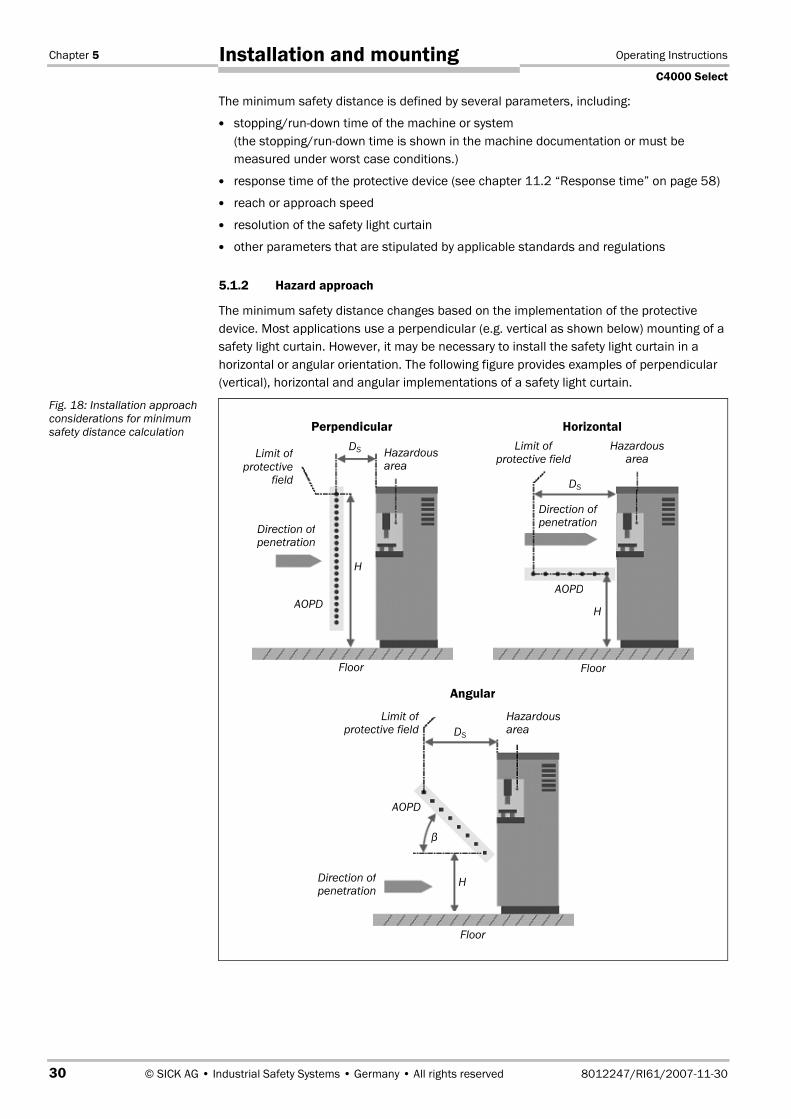
5.1.2 Hazard approach
The minimum safety distance changes based on the implementation of the protectivedevice. Most applications use a perpendicular (e.g. vertical as shown below) mounting of asafety light curtain. However, it may be necessary to install the safety light curtain in ahorizontal or angular orientation. The following figure provides examples of perpendicular(vertical), horizontal and angular implementations of a safety light curtain.
Fig. 18: Installation approachconsiderations for minimumsafety distance calculation
Limit ofprotective
field
Hazardousarea
Direction ofpenetration
Floor
DS
H
AOPD
Limit ofprotective field
Hazardousarea
Direction ofpenetration
Floor
DS
H
AOPD
Limit ofprotective field
Hazardousarea
Direction ofpenetration
Floor
DS
H
AOPD
β
Perpendicular Horizontal
Angular

Operating Instructions Chapter 5
C4000 Select
8012247/RI61/2007-11-30 © SICK AG • Industrial Safety Systems • Germany • All rights reserved 31
Installation and mounting
5.1.3 Minimum safety distance according to ANSI/CSA standards and OSHAregulations
The following table summarizes typical calculations of the minimum safety distance.
Approach Minimum safety distance calculation based on 30 mm objectdetection (resolution)
Perpendicular
β = 90º (± 5º)
Ds = Hs × (Ts + Tc + Tr + Tbm) + Dpf
Where Dpf is 3.08 inches (78.2 mm)
Horizontal
β = 0º (± 5º)
Ds = Hs × (Ts + Tc + Tr + Tbm) + Dpf
Where Dpf is 48 inches (1.21 m)
Angular
5º ≤ β ≤ 85º
For β ≥ 30º, use the perpendicular approach.
For β ≤ 30º, use the horizontal approach.
The minimum safety distance requirement is based on the beamthat is located the closest to the hazard.
This table presents summary information only and additional requirements may apply foryour application. Consult the relevant standards and regulations for additional require-ments related to the minimum safety distance calculation.
The following example shows the calculation of the minimum safety distance based onANSI B11.19, CAN/CSA Z434 and OSHA 29 CFR 1910.217 for a perpendicular (e.g. verti-cal) installation of a safety light curtain. Depending on the application and the ambientconditions, a different calculation may be necessary.
� First, calculate Ds using the following formula:
Ds = Hs × (Ts + Tc + Tr + Tbm) + Dpf
Where …
Ds = The minimum safety distance in inches (or mm) from the hazardous point to theprotective device
Hs = A parameter in inches/second or mm/second, derived from data on approachspeeds of the body or parts of the body.Often 63 inches/second is used for HS.
Ts = Stopping/run down time of the machine tool measured at the final controlelement
Tc = Stopping/run-down time of the control system
Tr = Response time of the entire protective device after light path interruption
Tbm = Additional response time allowed for brake monitor to compensate for wear
Dpf = Depth of penetration factor. An additional distance added to the overall safetydistance required. The value is based on the intrusion toward the hazardouspoint prior to detection by the safety light curtain. The Dpf for a perpendicular(vertical) safety light curtain with 30 mm (1.18 in) object sensitivitiy (resolution)can be approximated based on the following formula from ANSI/RIA R15.06:
Dpf (inches) = 3.4 × (object sensitivity – 0.276), but not less than 0.
= 3.4 × (1.18 – 0.276) = 3.08 in
Any additional response times that apply to your application must be accounted for in thiscalculation.
Tab. 15: Minimum safetydistance formula summaryper ANSI/CSA standards
Note

Chapter 5 Operating Instructions
C4000 Select
32 © SICK AG • Industrial Safety Systems • Germany • All rights reserved 8012247/RI61/2007-11-30
Installation and mounting
Example
Stopping/run-down time of the machine = 290 msResponse time after light path interruption = 30 msResolution of the light curtain = 30 mmTtotal = 290 ms + 30 ms = 320 ms = 0.32 sDs = (Hs × Ttotal) + Dpf
= (63 in/s × 0.32 s) + 3.08 in
= 23.25 in (591 mm)
5.1.4 Minimum safety distance according to EN 999 and EN 294
The following table summarizes typical calculations of the minimum safety distance.
Approach Minimum safety distance calculation based on 30 mm objectdetection (resolution) (mm)
Perpendicular
β = 90º (± 5º)
Ds = 2000 × T + 128
If Ds > 500 mm, using the formula above, then recalculate using:
Ds = 1600 × T + 128
The result of this second calculation cannot be less than 500 mm
Horizontal
β = 0º (± 5º)
Ds = 1600 × T + (1200 – 0.4 × H)
Where H is the mounting height and (1200 – 0.4 × H) must begreater than 850 mm
Angular
5º ≤ β ≤ 85º
For β ≥ 30º, use the perpendicular approach.
For β ≤ 30º, use the horizontal approach.
Ds applies to the furthest beam whose height is ≤ 1000 mm
This table presents summary information only and additional requirements may apply foryour application. Consult the relevant standards and regulations for additional require-ments related to the minimum safety distance calculation.
The following calculation shows an example calculation of the safety distance for a perpen-dicular (e.g. vertical) installation of a safety light curtain based on EN 999 and EN 294.
� First, calculate Ds using the following formula:
Ds = 2000 × T + 8 × (d – 14) [mm]
Where …
Ds = Safety distance [mm]3)
T = Stopping/run-down time of the machine
+ response time of the protective device after light path interruption [s]
d = Resolution of the light curtain [mm] i.e. 30 mm
The reach/approach speed is already included in the formula
� If the result Ds is ≤ 500 mm, then use the determined value as the safety distance
� If the result Ds is > 500 mm, then recalculate Ds as follows:
Ds = 1600 × T + 8 × (d – 14) [mm]
� If the new value Ds is > 500 mm, then use the newly determined value as the minimumsafety distance
� If the new value Ds is ≤ 500 mm, then use 500 mm as the safety distance
3) DS is referenced as “S” in EN 999 and EN 294.
Tab. 16: Minimum safetydistance formula summaryper EN 999 and EN 294when no floating blanking isimplemented

Operating Instructions Chapter 5
C4000 Select
8012247/RI61/2007-11-30 © SICK AG • Industrial Safety Systems • Germany • All rights reserved 33
Installation and mounting
Example
Stopping/run-down time of the machine = 290 msResponse time after light path interruption = 30 msResolution of the light curtain = 30 mmT = 290 ms + 30 ms = 320 ms = 0.32 s
Ds = 2000 × 0.32 + 8 × (30 – 14) = 768 mmDs > 500 mm, therefore:Ds = 1600 × 0.32 + 8 × (30 – 14) = 640 mm (25.2 inches)
5.1.5 Minimum distance to reflective surfaces
Maintain the minimum distance from reflective surfaces!
The light beams from the sender may be deflected by reflective surfaces. This can result infailure to identify personnel infringing on the protective device causing an operator to be atrisk. Ensure that your application adheres to the required minimum distance to reflectivesurfaces.
All reflective surfaces and objects (e.g. material bins) must be a minimum distance a fromthe light path between sender and receiver. The minimum distance a depends on thedistance D between sender and receiver.
The field of view of the sender and receiver optics is identical.
WARNING
Fig. 19: Minimum distance toreflective surfaces
Note
Reflective surface
Field of view Minimum distance a
Distance D sender–receiver

Chapter 5 Operating Instructions
C4000 Select
34 © SICK AG • Industrial Safety Systems • Germany • All rights reserved 8012247/RI61/2007-11-30
Installation and mounting
How to determine the minimum distance from reflective surfaces:
� Determine the distance D [m] sender–receiver.
� The minimum distance to the reflective surface a [mm] is shown in the diagram belowor may be calculated using the formula shown in Tab. 17.
Distance D [m]sender–receiver
Calculation of the minimum distance a from reflectivesurfaces
D ≤ 3 m a [mm] = 131
D > 3 m a [mm] = tan�(2.5°) × 1000 × D [m] = 43.66 × D [m]4)
5.2 Steps for mounting the device
Special features to note during mounting:
� Always mount the sender and receiver parallel to one another.
� During mounting, ensure that sender and receiver are aligned correctly. The optical lenssystems of sender and receiver must be located in exact opposition to each other; thestatus indicators must be mounted at the same height. The system connections of bothdevices must point in the same direction.
4) The maximum value used for D is 6 m for low scanning range and 19 m for high scanning range.
Fig. 20: Graph, minimumdistance from reflectivesurfaces
Tab. 17: Formula for thecalculation of the minimumdistance to reflectivesurfaces
WARNING
Fig. 21: Sender and receivermust not be rotated 180°with respect to each other
��

Operating Instructions Chapter 5
C4000 Select
8012247/RI61/2007-11-30 © SICK AG • Industrial Safety Systems • Germany • All rights reserved 35
Installation and mounting
� Observe the safety distance of the system during mounting. On this subject readchapter 5.1 “Determining the minimum safety distance” on page 29.
� Mount the safety light curtain such that the risk of failure to detect is excluded. Ensurethat the protective device cannot be bypassed by crawling underneath, reaching over,climbing between 2 beams, jumping over or moving the safety light curtain.
� Once the system is mounted, one or several of the enclosed self-adhesive informationlabels must be affixed:
– Use only information labels in the language which the users and operators of themachine understand.
– Affix the information labels such that they are easily visible by the users andoperators during operation. After attaching additional objects and equipment, theinformation labels must not be concealed from view.
– Operation with floating blanking: Affix the information label for floating blanking toeach receiver so configured. Mark the effective resolution on the information label.
– Affix the information label “Important Notices” to the system in close proximity tosender and receiver.
� When mounting a C4000 Select with integrated laser alignment aid, ensure that thelaser warning labels on the device remain visible. If the laser warning labels arecovered, e.g. on installation of the C4000 Select in a device column (accessory), youmust apply a laser warning label in an appropriate location in close proximity to thesender unit.
Fig. 22: The correctinstallation (above) musteliminate the errors (below)of reaching through andcrawling beneath

Chapter 5 Operating Instructions
C4000 Select
36 © SICK AG • Industrial Safety Systems • Germany • All rights reserved 8012247/RI61/2007-11-30
Installation and mounting
Sender and receiver can be mounted in four different ways:
� mounting with swivel mount bracket
� mounting with side bracket
� mounting with rigid mounting bracket
� mounting with pivoting mounting bracket
5.2.1 Mounting with swivel mount bracket
The swivel mount bracket is made of high-strength black plastic. The bracket is designedsuch that sender and receiver can still be accurately aligned even after the bracket hasbeen mounted.
Attach the screws of the swivel mount bracket with a torque of between 2.5 and 3 Nm.Higher torques can damage the bracket; lower torques provide inadequate protectionagainst vibration.
Note
Fig. 23: Composition of theswivel mount bracket
Part No. 2030510

Operating Instructions Chapter 5
C4000 Select
8012247/RI61/2007-11-30 © SICK AG • Industrial Safety Systems • Germany • All rights reserved 37
Installation and mounting
� Mount the bolts marked with to � on the operator side of the system to ensure thatthey remain accessible after mounting. The safety light curtain can then also be adjus-ted later.
� The mounting nuts and bolts are not included in the delivery.
Fig. 24: Mounting the C4000Select with swivel mountbracket
Notes
�
�
Chapter 5 Operating Instructions
C4000 Select
38 © SICK AG • Industrial Safety Systems • Germany • All rights reserved 8012247/RI61/2007-11-30
Installation and mounting
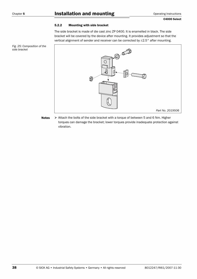
5.2.2 Mounting with side bracket
The side bracket is made of die cast zinc ZP 0400. It is enamelled in black. The sidebracket will be covered by the device after mounting. It provides adjustment so that thevertical alignment of sender and receiver can be corrected by ±2.5° after mounting.
� Attach the bolts of the side bracket with a torque of between 5 and 6 Nm. Highertorques can damage the bracket; lower torques provide inadequate protection againstvibration.
Fig. 25: Composition of theside bracket
Notes
Part No. 2019506

Operating Instructions Chapter 5
C4000 Select
8012247/RI61/2007-11-30 © SICK AG • Industrial Safety Systems • Germany • All rights reserved 39
Installation and mounting
� When mounting the side bracket ensure that the bolts marked and � remainaccessible, allowing you later to adjust and lock the safety light curtain in position.
� The mounting nuts and bolts are not included in the delivery.
Fig. 26: Mounting the C4000Select with side bracket
Notes
Sliding nut
Sliding nut
�

Chapter 5 Operating Instructions
C4000 Select
40 © SICK AG • Industrial Safety Systems • Germany • All rights reserved 8012247/RI61/2007-11-30
Installation and mounting
5.2.3 Mounting with rigid mounting bracket
The rigid mounting bracket is a black, powder-coated bracket without adjustment. It is onlysuitable for mounting surfaces on which it is not necessary to compensate for largemechanical tolerances. The alignment of the sender and receiver can be corrected aftermounting using only the slots.
� When mounting the rigid mounting bracket ensure that the four bolts marked and �remain accessible, allowing you later to adjust and lock the safety light curtain inposition.
� The mounting nuts and bolts are not included in the delivery.
Fig. 27: Rigid mountingbracket
Fig. 28: Mounting the C4000Select with rigid mountingbracket
Notes
Part No. 7021352
�Sliding nuts
Sliding nuts

Operating Instructions Chapter 5
C4000 Select
8012247/RI61/2007-11-30 © SICK AG • Industrial Safety Systems • Germany • All rights reserved 41
Installation and mounting
5.3 Laser alignmentThe C4000 Select provides an internal, collimated, visible class 1 laser to assist you withthe alignment of C4000 Select sender and receiver units. The laser used for aligning thesender to receiver is located in the C4000 Select sender unit. Further adjustments shouldbe performed at the C4000 Select receiver unit until the system is properly aligned.
To activate the laser, locate the button near the DIP switches in the C4000 Select senderunit. Press the button for more than 0.25 seconds. Once pressed and released, the laserwill be illuminated for four (4) minutes. If the button is pressed again, it will shut the laseroff.
The signal indicator on the C4000 Select receiver unit indicates the current state of align-ment between it and the corresponding sender unit. There are five (5) LEDs that are rela-ted to this function. When the first LED is yellow, the synchronization beam of the senderand receiver has been detected. As the percentage of beams increases, the number ofyellow LEDs that are illuminated also increase. When all five LEDs are illuminated yellow,the sender and receiver units are aligned, but there is a weak signal. When all five LEDsare illuminated green, the sender and receiver units are aligned with adequate signaldetected.
The laser alignment tool of the C4000 Select is rated tolaser safety class 1. Additional measures for screening thelaser radiation are not necessary.
This device meets the standard CDRH 21 CFR 1040.10 as well as EN 608251:2007.
There the following note is required: “Caution — use of controls or adjustments or perfor-mance of procedures other than those specified herein may result in hazardous radiationexposure!”
The laser is used to align the optics between a single sender and receiver pair. However,when a cascaded system is implemented, the laser from one C4000 Select sender couldcause a lockout condition in a receiver in another C4000 Select sender/receiver pair inthe cascade. If this lockout condition occurs, cycle power and perform the alignment pro-cedure again.
Note

Chapter 5 Operating Instructions
C4000 Select
42 © SICK AG • Industrial Safety Systems • Germany • All rights reserved 8012247/RI61/2007-11-30
Installation and mounting
Do not look into the laser aperture!
The laser alignment aid of the C4000 Select sender unit is rated Class 1 (eye safe) toapplicable standards. However, as with any source of radiated energy (e.g. light), pro-longed, direct exposure to laser light may cause damage to vision.
Fig. 29: C4000 Select laseralignment location and labeldetails
WARNING
Laser target area,located on C4000 Select
receiver unit
The laser warning label has been incorporated into the devicetype label information located on the back of the C4000 Selectsender unit just above the system end cap.
Aperture of integrated laser,located on C4000 Select
sender unit
� �

Operating Instructions Chapter 6
C4000 Select
8012247/RI61/2007-11-30 © SICK AG • Industrial Safety Systems • Germany • All rights reserved 43
Electrical installation
6 Electrical installation
Switch the entire machine/system off line!
The machine/system could inadvertently start up while you are connecting the devices.
� Ensure that the entire machine/system is disconnected during the electricalinstallation.
Connect OSSD1 and OSSD2 separately!
You are not allowed to connect OSSD1 and OSSD2 together, otherwise signal safety willnot be ensured.
� Ensure that the machine controller processes the two signals separately.
Contactors connected in series must be positively guided and monitored.
� The two outputs are protected against short-circuits to 24 V DC and 0 V. When the lightpath is clear, the signal level on the outputs is HIGH DC (at potential), when the lightbeams are interrupted or there is a device fault the outputs are LOW DC.
� The safety light curtain C4000 Select meets the interference suppression requirements(EMC) for industrial use (interference suppression class A). When used in residentialareas it can cause interference.
� To ensure full electromagnetic compatibility (EMC), functional earth (FE) must beconnected.
� The external voltage supply of the devices must be capable of buffering brief mainsvoltage failures of 20 ms as specified in EN 60�2041. The power supply unit mustprovide safe isolation (SELV/PELV). Suitable power supplies are available asaccessories from SICK (see section 12.11 “Accessories” on page 75).
� System connections and extension connections in a cascaded system must be connect-ed only if the system is off line.
WARNING
Notes

Chapter 6 Operating Instructions
C4000 Select
44 © SICK AG • Industrial Safety Systems • Germany • All rights reserved 8012247/RI61/2007-11-30
Electrical installation
6.1 Bottom end cap with system connection M12�× 5 male
Pin No. Wire Color5) Sender Receiver Description
1 Brown +24 V DC +24 V DC Supply voltage (+)
2 White – OSSD1 Output Signal Switching Device 1
3 Blue 0 V DC 0 V DC Supply voltage (–)
4 Black – OSSD2 Output Signal Switching Device 2
5 Gray FE FE Functional Earth
6.2 Bottom end cap with system connection M12�× 5 maleand extended I/O connection M12�× 5 female
In addition to the system connection, the C4000 Select may have an extended I/O connec-tion included in the same end cap. This extended I/O connection is used for cascading ad-ditional protective devices (e.g. another C4000 Select or SICK S300/S3000 safety laserscanner). Connection of the safety-rated outputs associated with these additional casca-ded devices occurs at the extended I/O connection of the C4000 Select receiver.
Only PNP-type semiconductor-based safety outputs may be connected via the extendedI/O connection. Electro-mechanical devices (i.e. contact-based devices) are strictly prohibi-ted from being connected to the extended I/O connection.
When cascading C4000 Select devices via the extended I/O connection, the sender unitmay also utilize an extended I/O connection for ease of wiring.
Electro-mechical devices are not to be connected to the safety inputs on the extendedI/O connection!
Extended I/O connections allow you to cascade additional devices to the C4000 Select.When implementing such a system, you are only allowed to connect PNP-type semiconduc-tor safety-rated devices to the safety inputs on the extended I/O connection. Electro-mechanical devices (e.g. emergency stops, safety interlock switches, etc.) shall not beconnected to the safety inputs on the extended I/O connection!
5) Wire colors shown in this table are in accordance with SICK C4000 Select M12�×5 cable accessories. Whenutilizing other M12�×5 cable manufacturers’ cables, you may need to verify that the conductor colors shown inthis table correspond with the cable that you are using.
Fig. 30: Pin assignment forsystem connection M12�×5male
Tab. 18: Pin assignment forsystem connection M12�×5male
WARNING

Operating Instructions Chapter 6
C4000 Select
8012247/RI61/2007-11-30 © SICK AG • Industrial Safety Systems • Germany • All rights reserved 45
Electrical installation
Male Female
Pin No. Wire Color6) Sender Receiver Description
1 Brown +24 V DC +24 V DC Supply voltage (+)
2 White – OSSD1 Output Signal Switching Device 1
3 Blue 0 V DC 0 V DC Supply voltage (–)
4 Black – OSSD2 Output Signal Switching Device 2
5 Gray FE FE Functional Earth
Pin No. Wire Color6) Sender Receiver Description
1 Brown +24 V DC +24 V DC Supply voltage (+)
2 White – IN1 Safe input 1
3 Blue 0 V DC 0 V DC Supply voltage (–)
4 Black – IN2 Safe input 2
5 Gray FE FE Functional Earth
6) Wire colors shown in this table are in accordance with SICK C4000 Select M12�×5 cable accessories. Whenutilizing other M12�×5 cable manufacturers’ cables, you may need to verify that the conductor colors shown inthis table correspond with the cable that you are using.
Fig. 31: Pin assignment forsystem connection M12�×5male and M12�× 5 female
Tab. 19: Pin assignment forsystem connection M12�×5male
Tab. 20: Pin assignment forextended I/O connectionM12�×5 female

Chapter 6 Operating Instructions
C4000 Select
46 © SICK AG • Industrial Safety Systems • Germany • All rights reserved 8012247/RI61/2007-11-30
Electrical installation
6.3 Top end cap with extended I/O M12�× 5 femaleconnection
In addition to the end cap with the system connection, the C4000 Select may also utilize atop end cap that has an extended I/O connection that is used for cascading additionalprotective devices (e.g. another C4000 Select or SICK S300/S3000 safety laser scanner).Connection of the safety-rated outputs associated with these additional cascaded devicesoccurs at the C4000 Select receiver extended I/O connection. When an extended I/O endcap is used on the top of the C4000 Select receiver unit, the integrated LED cannot beused. If an integrated LED is required, specify a combined system and extended I/Obottom end cap when ordering. Refer to section 6.2 “Bottom end cap with systemconnection M12�× 5 male and extended I/O connection M12�×5 female” on page 44 foradditional information.
Only PNP-type semiconductor-based safety outputs may be connected via the extendedI/O connection. Electro-mechanical devices (i.e. contact-based devices) are strictly prohibi-ted from being connected to the extended I/O connection.
When cascading C4000 Select devices via the extended I/O connection, the sender unitmay also utilize an extended I/O connection for ease of wiring.
Electro-mechical devices are not to be connected to the safety inputs on the extendedI/O connection!
Extended I/O connections allow you to cascade additional devices to the C4000 Select.When implementing such a system, you are only allowed to connect PNP-type semiconduc-tor safety-rated devices to the safety inputs on the extended I/O connection. Electro-mechanical devices (e.g. emergency stops, safety interlock switches, etc.) shall not beconnected to the safety inputs on the extended I/O connection!
Pin No. Wire Color7) Sender Receiver Description
1 Brown +24 V DC +24 V DC Supply voltage (+)
2 White – IN1 Safe input 1
3 Blue 0 V DC 0 V DC Supply voltage (–)
4 Black – IN2 Safe input 2
5 Gray FE FE Functional Earth
7) Wire colors shown in this table are in accordance with SICK C4000 Select M12�×5 cable accessories. Whenutilizing other M12�×5 cable manufacturers’ cables, you may need to verify that the conductor colors shown inthis table correspond with the cable that you are using.
WARNING
Fig. 32: Pin assignment forextended I/O connectionM12�×5 female
Tab. 21: Pin assignment forend cap with extended I/Oconnection M12�×5 female

Operating Instructions Chapter 7
C4000 Select
8012247/RI61/2007-11-30 © SICK AG • Industrial Safety Systems • Germany • All rights reserved 47
Commissioning
7 Commissioning
Commissioning requires a thorough check by qualified safety personnel!
Before you operate a system protected by the C4000 Select safety light curtain for the firsttime, make sure that the system is first checked and released by qualified safety person-nel. Please read the notes in chapter “On safety” on page 9.
7.1 Display sequence during power-upAfter the system is activated, sender and receiver go through a power-up cycle. The 7seg-ment display indicates the device status during the power-up cycle.
The display values have the following meaning:
Display Meaning
�, �, , �,�, �, �, �
Testing the 7segment display. All segments are activatedsequentially.
0.5 s (typical). Is displayed only at the receiver and only in operationwith high scanning range.
�, � or 0.5 s (typical). Non-coded operation or operation with code 1 or 2.
Other display Device error. See “Fault diagnosis” on page 52.
7.2 Aligning sender and receiverAfter the light curtain has been mounted and connected, the sender and receiver must bealigned in relation to each other. The light beams emitted by the sender must hit the re-ceiver with pin-point accuracy. For additional information regarding the laser alignmentcapability of the C4000 Select, see section 5.3 “Laser alignment” on page 41.
How to align sender and receiver in relation to each other:
Secure the plant/system. No dangerous movement possible!
Make sure that the dangerous state of the machine is (and remains) switched off! Duringthe alignment process, the outputs of the safety light curtain are not allowed to have anyeffect on the machine.
� Loosen the clamping bolts which hold the light curtain in place.
� Switch on the power supply to the light curtain.
� Watch the five (5) alignment LEDs on the receiver unit. As the number of illuminatedLEDs increases, an increased percentage of beams are aligned between sender andreceiver unit. When all beams are aligned, all five (5) LEDs will be illuminated. If all five(5) LEDs are yellow, then there is a weak signal between sender and receiver. If all five(5) LEDs are green, then the alignment is correct with adequate signal strength.
� Using the clamping bolts, fix the light curtain in place.
� Switch the power supply off and then back on again and check the five (5) alignmentLEDs to ensure alignment is still adequate.
WARNING
Tab. 22: Displays shownduring the power-up cycle
WARNING

Chapter 7 Operating Instructions
C4000 Select
48 © SICK AG • Industrial Safety Systems • Germany • All rights reserved 8012247/RI61/2007-11-30
Commissioning
� The laser alignment mode will be active for four (4) minutes after activation. To reacti-vate the laser alignment mode, press the laser activation button on the sender device.
� If you wish to readjust the alignment later, press the laser activation button on theC4000 Select sender unit.
� The safety outputs of a host C4000 Select system that is cascaded will remain inactive(low) i.e. red until all guests have been correctly aligned and their corresponding outputsare active (high) i.e. green.
7.3 Test notesThe purpose of the tests described in the following is to confirm the safety requirementsspecified in the national/international rules and regulations, especially the safety require-ments in the Machine and Work Equipment Directive (EU Conformity).
These tests are also used to identify if the protection is affected by external light sourcesor other unusual ambient effects.
These tests must therefore always be performed.
7.3.1 Tests before the first commissioning
� Check the effectiveness of the protective device mounted to the machine, using allselectable operating modes as specified in the checklist in the annex (see 13.2 onpage 78).
� Ensure that the operating personnel of the machine in which the C4000 Select is in-stalled are correctly instructed by qualified safety personnel before being allowed tooperate the machine. Instructing the operating personnel is the responsibility of themachine owner.
� Annex 13.2 of this document shows a checklist for review by the manufacturer andOEM. Use this checklist as a reference before commissioning the system for the firsttime.
7.3.2 Regular inspection of the protective device by qualified safety personnel
� Check the system, following the inspection intervals specified in the national rules andregulations. This procedure ensures that any changes on the machine or manipulationsof the protective device are detected before use/re-use.
� If any modifications have been made to the machine or the protective device, or if thesafety light curtain has been changed or repaired, the system must be checked again asspecified in the checklist in the annex.
Notes

Operating Instructions Chapter 7
C4000 Select
8012247/RI61/2007-11-30 © SICK AG • Industrial Safety Systems • Germany • All rights reserved 49
Commissioning
7.3.3 Daily functional checks of the protective device
The effectiveness of the protective device must be checked daily by a specialist or byauthorized personnel, using the correct test rod.
Always test along the complete hazardous area to be protected, never solely at themounting position of the light curtain.
How to check the effectiveness and correct function of the safety light curtain:
� Select the correct test rod depending on device resolution. By means of the configura-tion, the entire system or individual areas can have a physical resolution that is diffe-rent to the effective resolution, e.g. in case of floating blanking. In this case you mustselect the test rod to suit the effective resolution. The effective resolution is describedwith the related function in chapter 4.
Example: –physical resolution 30 mm– operation with single beam floating blanking– effective resolution 50 mm
� Use a test rod for a resolution of 50 mm.
Do not operate the machine if the output LED turns green during the test!
If the output LED turns green during the test, even for a short period, work must stop atthe machine. In this case the mounting and the configuration of the safety light curtainmust be checked by qualified safety personnel (see chapter 5).
� Before inserting the test rod, ensure that the output LED is green and the protectivefield is clear of obstruction. Once the test rod is inserted, the output LED should remainred during the entire time the test rod is present in the protective field. This test ismeaningless if it is completed when the output LED is already red before the test rodhas been inserted into the protective field.
� Move the test rod slowly through the protective field to be tested, as shown in inFig. 33.
� Then move the test rod along the edges of the protective field, as shown in � in Fig. 33.This procedure allows you to test if the point-of-operation/reaching around protection isfunctioning correctly (see 5.2 “Steps for mounting the device” on page 34).
� If you use one or more deflector mirrors (e.g. PNS), then also guide the test rod slowlythrough the protective field directly in front of the mirrors.
During all tests, the output LED should remain red.
Note
WARNING
Note
Fig. 33: Daily checks of theprotective device �

Chapter 8 Operating Instructions
C4000 Select
50 © SICK AG • Industrial Safety Systems • Germany • All rights reserved 8012247/RI61/2007-11-30
Configuration
8 ConfigurationDefault delivery status
As delivered the C4000 Select is configured ready for protective operation. The followingtables indicate the default switch settings for C4000 Select sender and receiver units:
Switch Description Default setting (out of box)
Beam code 1 select OFF i.e. no beam coding
Beam code 2 select OFF i.e. no beam coding
Switch Description Default setting (out of box)
High range select OFF i.e. low range
Extended I/O enable OFF i.e. no extended I/O
Beam code 1 select OFF
Beam code 2 select OFFi.e. no beam coding
Floating blanking enable OFF i.e. disabled
One beam floating blanking OFF i.e. disabled
Two beam floating blanking OFF i.e. disabled
Switch Description Default setting (out of box)
High range select OFF i.e. low range
Extended I/O enable ON i.e. extended I/O enabled
Beam code 1 select OFF
Beam code 2 select OFFi.e. no beam coding
Floating blanking enable OFF i.e. disabled
One beam floating blanking OFF i.e. disabled
Two beam floating blanking OFF i.e. disabled
Tab. 23: Default DIP switchsettings for C4000 Selectsender unit
Tab. 24: Default DIP switchsettings for C4000 Selectreceiver unit when extendedI/O connection is not present
Tab. 25: Default DIP switchsettings for C4000 Selectreceiver unit when extendedI/O connection is available

Operating Instructions Chapter 9
C4000 Select
8012247/RI61/2007-11-30 © SICK AG • Industrial Safety Systems • Germany • All rights reserved 51
Care and maintenance
9 Care and maintenanceThe C4000 Select safety light curtain is maintenance-free. The front screen of the C4000Select safety light curtain and any additional front screen(s) (see “Additional front screen(weld spark guard)” on page 74) should be cleaned at regular intervals and when dirty.
� Do not use aggressive cleaning agents.
� Do not use abrasive cleaning agents.
Static charges cause dust particles to be attracted to the front screen. You can preventthis effect by using the antistatic plastic cleaner (SICK part number 5600006) and theSICK lens cloth (part number 4003353).
How to clean the front screen and/or the additional front screen (optional extra):
� Use a clean and soft brush to remove dust from the front screen.
� Then wipe the front screen with a clean and damp cloth.
� After cleaning, check the position of sender and receiver to make sure that theprotective device cannot be bypassed (reaching over, under or around).
� Verify the effectiveness of the protective device as described in chapter 7.3 “Testnotes” on page 48.
Only factory authorized personnel may repair C4000 Select devices!
The C4000 Select is designed for maintenance-free operation. When a device requiresrepair, contact your local SICK representative to coordinate the repair or exchange of thedevice. Do not attempt to repair the device yourself! Any attempt to repair your C4000Select device (e.g. removal of end cap, etc.) will void product warranty and may lead to theloss of the safety function!
Use of controls or adjustments or performance of procedures other than those specified inthis document may result in hazardous radiation exposure per EN 60�825. Do not attemptto disassemble this sensor for repair! A defective device must be returned to the manu-facturer or a regional repair center authorized by the manufacturer for the repair of thisdevice.
Note
Note
WARNING

Chapter 10 Operating Instructions
C4000 Select
52 © SICK AG • Industrial Safety Systems • Germany • All rights reserved 8012247/RI61/2007-11-30
Fault diagnosis
10 Fault diagnosisThis chapter describes how to identify and rectify errors and malfunctions during theoperation of the safety light curtain.
10.1 What to do in case of faults
Cease operation if the cause of the malfunction has not been clearly identified!
Stop the machine if you cannot clearly identify or allocate the error and if you cannot safelyremedy the malfunction.
The system state lock-out
In case of certain faults or an erroneous configuration, the system can go into the lockoutstatus. The 7segment display on the safety light curtain then indicates a number rangingfrom 1 through 6. To place the device back in operation:
� Rectify the cause of the fault as per Tab. 28.
� Switch the power supply for the C4000 Select off and on again (e.g. by unplugging thesystem connection and reinserting it).
10.2 SICK SupportIf you cannot remedy an error with the help of the information provided in this chapter,please contact your local SICK representative.
10.3 Error displays of the diagnostics LEDsThis chapter explains the meaning of the error displays of the LEDs and how to respond.Please refer to the description in chapter 3.4 “Status indicators and C4000 Selectmessage center” on page 18.
LED Name Display Possible cause Rectification
POWER � OffNo operating voltage, orvoltage too low
� Check the voltage supplyand activate, if necessary.
REPLACE � RedThe sender unit has detectedan internal error.
� Cycle power. If the errorpersists, replace sender unit
WARNING
Tab. 26: C4000 Select LEDtroubleshooting on senderunit

Operating Instructions Chapter 10
C4000 Select
8012247/RI61/2007-11-30 © SICK AG • Industrial Safety Systems • Germany • All rights reserved 53
Fault diagnosis
LED Name Display Possible cause Rectification
OUTPUT � Off No operating voltage, orvoltage too low
� Check the voltage supplyand activate, if necessary.
EXT I/O � Red Extended I/O safety inputsare inactive (low) i.e. OFF
� Check guest device(s) toensure that their outputsare active (high).
� Check wiring for errors.
� Check DIP switches toensure that the settingsare correct
ALIGNMENTLEDs
Not allLEDs are� Green
Not all beams are alignedbetween sender andreceiver units
� Check alignment andmake any necessaryadjustments in order tohave all five alignmentLEDs � Green
� Clean C4000 Select frontwindows
Tab. 27: C4000 Select LEDtroubleshooting on receiverunit

Chapter 10 Operating Instructions
C4000 Select
54 © SICK AG • Industrial Safety Systems • Germany • All rights reserved 8012247/RI61/2007-11-30
Fault diagnosis
10.4 Error displays of the 7segment displayThis chapter explains the meaning of the error displays of the 7segment display and howto respond to the messages. Please refer to chapter 3.4 “Status indicators and C4000Select message center” on page 18 for a description of the 7segment display.
Display Possible cause Rectification
�
An internal error has beendetected
� Cycle power. If the errorcondition persists,replace receiver unit
�A configuration error hasbeen detected
� Check DIP switch settings
�
Receiver unit has detectedbeams from multiple senderunits
� Add beam coding forguest segment(s)
�
Power supply voltage too low � Check the supply voltageand the power supply. Ifnecessary, replacedefective components
�
A fault or unexpected statehas been detected at theOSSDs on the systemconnection (e.g. overcurrent,stuck-at-high, or stuck-at-low)
� Check system wiring forerrors
7segmentdisplay
�
An unexpected signal hasbeen detected at theextended I/O connection(e.g. discrepancy error oractive signal at extended I/Osafety inputs when extendedI/O is disabled)
� Verify guest device safetyoutputs are either bothactive (high) or inactive(Low) (e.g. equivalent)
� Check guest device(s)wiring to the C4000Select host device.
� Verify guest device isoperating correctly
� If extended I/O function isdisabled, verify no guestdevice is connected atextended I/O connection
� If no extended I/Oconnection is present andthis error code exists,replace device
Tab. 28: Error displays of the7segment display

Operating Instructions Chapter 11
C4000 Select
8012247/RI61/2007-11-30 © SICK AG • Industrial Safety Systems • Germany • All rights reserved 55
Technical specifications
11 Technical specifications
11.1 Data sheetMinimum Typical Maximum
General system data
Protective field height, dependingon type
300 mm 1800 mm
Resolution 30 mm
Scanning range, DIP switchconfigurable
Low range 0…6 m 0…7.5 m8)
High range 5…19 m 5…21 m8)
Protection class(EN 50�178:199710)9)
III
Enclosure rating (IEC 60�529) IP 65
Supply voltage UV at device10) 19.2 V DC 24 V DC 28.8 V DC
Residual ripple11) ±10�%
Synchronization Optical, without separate synchronization
Type according to IEC 61�496 Type 4
SIL CL according to IEC 62�06112) SIL CL 3
Category/performance level accor-ding to EN ISO 13�8491:200612)
Category 4/PL e
SIL according to IEC 61�508 SIL 3
PFHd stand-alone 1800 mm 1.5 × 10⁻⁸
PFHd host-guest-guest 1800 mm 3.2 × 10⁻⁸
Mission time/proof test interval 20 years
Category according to EN 954113) Category 4
Power-up delay of sender andreceiver before ready
8 s
� Sender unit
Wavelength of sender 950 nm
Power consumption See Tab. 30
Permissible line resistance
Supply lead 1 �
8) On the utilization of this protective field width, it must be expected the yellow alignment LEDs will be yellow(cleaning or realignment required). The system then only has a reserve of 30�%.
9) Safety extra-low voltage SELV/PELV.10) The external voltage supply must be capable of buffering brief mains voltage failures of 20 ms as specified in
EN 60�2041. Suitable power supplies are available as accessories from SICK.11) Within the limits of UV.12) For detailed information regarding the accurate interpretation of this data, please contact your local SICK
representative.13) EN 9541 is valid until 29.11.2009. After this date, only its successor EN ISO 13�8491:2006 may be used.
Tab. 29: Data sheet C4000Select

Chapter 11 Operating Instructions
C4000 Select
56 © SICK AG • Industrial Safety Systems • Germany • All rights reserved 8012247/RI61/2007-11-30
Technical specifications
Minimum Typical Maximum
Alignment laser Class 1 in accordance with IEC 60�8251:2007 and21 CFR 1040.10 and 1040.11 except fordeviations pursuant to Laser Notice No. 50, June24, 2007, optical output power ≤ 390 µW CWλ typical = 650 nm
Weight, type dependent Depending on protective field height (see page 63)
� Receiver unit
Switching outputs (OSSDs) Dual-channel, PNP semiconductor, short-circuitprotected14), cross-circuit monitored
Response time See chapter 11.2 on page 58Switch off time15) 100 msSwitching voltage16) 17) HIGH(active, Ueff)
UV – 2.25 V DC 24 V DC UV
Switching voltage16) LOW(inactive)
0 V 0 V 2.0 V DC
Switching current 0 mA 500 mALeakage current18) 0.25 mALoad capacity 2.2 µFSwitching sequence Depending on load inductanceLoad inductance19) 2.2 HTest pulse data20)
Test pulse width 120 µs 150 µs 300 µsTest pulse rate 3 1/s 5 1/s 10 1/s
Permissible line resistancebetween device and load21) 2.5 �Supply lead 1 �
Power consumption See Tab. 30
14) Applies to the voltage range between –30 V DC and +30 V DC.15) Switch off time represents the minimum amount of time that the OSSDs will be switched off when the C4000
Select transitions to an inactive (low) (i.e. red) state.16) As per IEC 61�1312.17) On the device plug.18) In the case of a fault (0 V cable open circuit) the max. leakage current flows in the OSSD cable. The down-
stream controller must detect this status as LOW. A FPLC (Fail-safe Programmable Logic Controller) must beable to identify this status.
19) The maximum rated load inductance is higher with lower switching sequence.
20) When active, the outputs are tested cyclically (brief LOW). When selecting the downstream controllers, makesure that the test pulses do not result in deactivation when using the above parameters.
21) Make sure to limit the individual line core resistance to the downstream controller to this value to ensure thata short-circuit between the outputs is safely detected. (Also note EN 60�204 Electrical Machine Equipment,Part 1: General Requirements.)

Operating Instructions Chapter 11
C4000 Select
8012247/RI61/2007-11-30 © SICK AG • Industrial Safety Systems • Germany • All rights reserved 57
Technical specifications
Minimum Typical Maximum
Extended I/O input type(according to EN 61�1312)
Type 322). Dual-channel, PNP semiconductor,externally short-circuit protected, externally cross-circuit monitored e.g. from an S3000 safety laserscanner or another C4000 Select receiver
Input voltage23) HIGH 11 V DC 24 V DC 30 V DC
Input current HIGH 3 mA 5 mA 7 mAInput voltage LOW –30 V DC 0 V DC 5 V DCInput current LOW –1.2 mA 0 mA 2.5 mA24)
Input capacitance 5 nFInput test pulse filtering25)
Test pulse rate 160/sTest pulse gap 700 µs
Safe input discrepancy time 20 ms
Operating data
System connection M12�×5, male
Maximum cable length26) 30 m
Extension connection M12�×5, female
Maximum cable length 10 m
Ambient operating temperature 0°C +55°CAir humidity (non-concensing) 15�% 95�%Storage temperature –25°C +70°C (≤24 h)Enclosure rating27) IP 65Housing cross-section 52 mm × 55.5 mmVibration resistance 5 g, 10-55 Hz acc. to IEC 60�06826Shock resistance 10 g, 16 ms acc. to IEC 60�068229
Environmental data, materials
Housing Aluminium alloy ALMGSI 0.5 (powder coated)
Front screen Polycarbonate, scratch-resistant coating
End caps Polyamide 6.6 CF30
Packaging Corrugated cardboard with Instapak® inlays
Circuit boards Glass-fibre reinforced epoxy resin with flameretarding agent TBBPA
22) The “Type” designation listed here describes the kind of inputs that may be connected to the extended I/Osafety input connection. This particular designation is not related to the “Type” designation defined byIEC 61�4961, 2.
23) As per IEC 61�1312, type 3.24) Maximum leakage current allowed, even in the event of an error or fault condition.25) These values indicate the filtering capability of the C4000 Select in evaluating OSSD signals at the extended
I/O safety capable inputs without generating a stop condition based on the test pulse occurrence.26) Depending on load, power supply and wire cross-section. The technical specifications must be observed; e.g.
supply voltage and permissible line resistance.27) In order to satisfy enclosure rating, the cover plate over the DIP switches must be secured correctly. Further,
system and extended I/O cables must be rated IP 65 or better and must also be attached to the C4000 Selectcorrectly. You must use protective caps that are suitable for IP 65 enclosure rating for any unused connectors.

Chapter 11 Operating Instructions
C4000 Select
58 © SICK AG • Industrial Safety Systems • Germany • All rights reserved 8012247/RI61/2007-11-30
Technical specifications
Power consumption
Protective height Sender unit Receiver unit Sender/receiver pair
300 mm 4.9 W 7.6 W 12.5 W
600 mm 5.3 W 7.9 W 13.2 W
900 mm 5.7 W 8.1 W 13.8 W
1200 mm 6.1 W 8.4 W 14.5 W
1500 mm 6.5 W 8.6 W 15.1 W
1800 mm 6.9 W 8.8 W 15.7 W
11.2 Response timeThe response time depends on the following parameters:
� number of beams
� beam coding
� configuration of floating blanking
� number of cascaded systems
� the output signal switching device used
How to determine the response time of the system:
� Determine the response time of the individual components of the system.
– The response time of a C4000 Select standalone or host system is described in sec-tion 11.2.1 “Calculating the host/standalone response time” on page 58.
– The response time for guest 1 using a C4000 Select system or S300/S3000 safetylaser scanner as guest 1 is described in section 11.2.2 “Calculating the guest 1response time” on page 59.
– The response time for guest 2 using a C4000 Select system as guest 2 is describedin section 11.2.3 “Calculating the guest 2 response time” on page 60.
You must also consider other components of the response time when performing mini-mum safety distance calculations. Other components include, but are not limited to, safetyinterfaces, safety communication networks, machine stopping time, etc. See section 5.1.1“Minimum safety distance to the hazardous area” on page 29 for additional information.
11.2.1 Calculating the host/standalone response time
The following table provides details for C4000 Select response times based on configura-tion with (beam code 1 or beam code 2) or without beam coding (uncoded operation). Theinformation presented in this table is then used to calculate the host/standalone C4000Select response time.
Protective height
Beam Coding 300 mm 600 mm 900 mm 1200 mm 1500 mm 1800 mm
Uncoded 9 ms 11 ms 12 ms 13 ms 14 ms 15 ms
Beam code 1/2 12 ms 15 ms 18 ms 21 ms 24 ms 27 ms
Tab. 30: C4000 Select powerconsumption information
Tab. 31: Response time ofthe C4000 Select for applica-tions with and without beamcoding

Operating Instructions Chapter 11
C4000 Select
8012247/RI61/2007-11-30 © SICK AG • Industrial Safety Systems • Germany • All rights reserved 59
Technical specifications
Identify the response time value that corresponds to your C4000 Select based on thebeam code DIP switch setting (i.e. Uncoded, Beam code 1 or Beam code 2 operation) andthe protective height that is used and then complete the following table:
Line Description Value
1 C4000 Select response time from Tab. 31 above
2 When floating blanking is enabled, multiply the value from line 1 by0.50 and enter the result as the value for line 2.
3 Add lines 1 and 2 together and enter the value for line 3.
Line 3 value is the response time for the C4000 Select host.
11.2.2 Calculating the guest 1 response time
The information presented in Tab. 31 “Response time of the C4000 Select for applicationswith and without beam coding” also applies for C4000 Select sender/receiver pairs thatare in the guest 1 position. For applications where the guest 1 device is an S300/S3000safety laser scanner, consult the operating instructions of the S300 or S3000 for theresponse time value that will be used in line 4 of the table below.
Identify the response time value that corresponds to your C4000 Select guest 1 based onthe beam code DIP switch setting (i.e. Uncoded, Beam code 1 or Beam code 2 operation)and the protective height that is used.
Line Description Value
4 Enter the value for the guest 1 response time based on Tab. 31 forthe C4000 Select, or the value determined for the S300/S3000safety laser scanner
5 If the device in line 4 is a C4000 Select and floating blanking isenabled, multiply the value on line 4 by 0.50 and enter the result asthe line 5 value.
6 Add lines 4 and 5 together. Enter the result as the line 6 value.
7 Multiply line 1 from the host response time calculation by 0.50 andthen add 2 ms. Enter the result as the line 7 value.
8 Add lines 6 and 7 together. Enter the result in line 8 value.
Line 8 value is the response time of the guest 1 device.
Tab. 32: Response time cal-culation of host/standaloneC4000 Select safety lightcurtain
Tab. 33: Response time cal-culation of guest 1 devices ina host-guest 1 system withC4000 Select as host

Chapter 11 Operating Instructions
C4000 Select
60 © SICK AG • Industrial Safety Systems • Germany • All rights reserved 8012247/RI61/2007-11-30
Technical specifications
11.2.3 Calculating the guest 2 response time
The information presented in Tab. 31 “Response time of the C4000 Select for applicationswith and without beam coding” also applies for C4000 Select sender/receiver pairs thatare in the guest 2 position. Identify the response time value that corresponds to yourguest 2 C4000 Select based on the beam code DIP switch setting (i.e. Uncoded, Beamcode 1 or Beam code 2 operation) and the protective height that is used.
Line Description Value
9 Enter the value for the guest 2 response time based on Tab. 31 forthe C4000 Select
10 If floating blanking is enabled, multiply the value on line 9 by 0.50and enter the result as the line 10 value
11 Add lines 9 and 10 together. Enter the result in line 11 value
12 Multiply line 1 from the host response time calculation by 0.50 andthen add 2 ms. Enter the result as the line 12 value
13 Multiply line 4 from the guest 1 response time calculation by 0.50and then add 2 ms. Enter the result as the line 13 value
14 Add lines 11, 12 and 13 together. Enter the result in line 14 value.
Line 14 value is the response time of the guest 2 device.
11.2.4 Response time calculation examples
Standalone C4000 Select system
The calculation example shown below is based on the following:
� C4000 Select, 300 mm protective height, no beam coding, no floating blanking
Line Description Value
1 C4000 Select response time from Tab. 31 9 ms
2 When floating blanking is enabled, multiply the value from line 1 by0.50 and enter the result as the value located for line 2
0 ms
3 Add lines 1 and 2 together and enter the value for line 3.
Line 3 value is the response time for the C4000 Select host.9 ms
Tab. 34: Response time cal-culation of guest 2 devices ina host-guest 1-guest 2system with C4000 Select
Tab. 35: Response timecalculation for standaloneC4000 Select system

Operating Instructions Chapter 11
C4000 Select
8012247/RI61/2007-11-30 © SICK AG • Industrial Safety Systems • Germany • All rights reserved 61
Technical specifications
C4000 Select host and S3000 safety laser scanner as guest 1
The calculation example shown below is based on the following:
� C4000 Select, 900 mm protective height, beam code 1, with 1 beam floating blanking
� S3000 safety laser scanner as guest 1 with 60 ms response time based on scannerconfiguration
Line Description Value
1 C4000 Select response time from Tab. 31 18 ms
2 When floating blanking is enabled, multiply the value from line 1 by0.50 and enter the result as the value for line 2
9 ms
3 Add lines 1 and 2 together and enter the value for line 3.
Line 3 value is the response time for the C4000 Select host.27 ms
4 Enter the value for the guest 1 response time based on Tab. 31 forthe C4000 Select, or the value determined for the S300/S3000safety laser scanner
60 ms
5 If the device in line 4 is a C4000 Select and floating blanking isenabled, multiply the value on line 4 by 0.50 and enter the result asthe line 5 value.
0 ms
6 Add lines 4 and 5 together. Enter the result as the line 6 value. 60 ms
7 Multiply line 1 from the host response time calculation by 0.50 andthen add 2 ms. Enter the result as the line 7 value.
11 ms
8 Add lines 6 and 7 together. Enter the result in line 8 value.
Line 8 value is the response time of the guest 1 S3000 safetylaser scanner.
71 ms
Tab. 36: Response time cal-culation for C4000 Selecthost and S3000 safety laserscanner as guest 1

Chapter 11 Operating Instructions
C4000 Select
62 © SICK AG • Industrial Safety Systems • Germany • All rights reserved 8012247/RI61/2007-11-30
Technical specifications
Host-guest 1-guest 2 C4000 Select system
The calculation example shown below is based on the following:
� Host C4000 Select, 900 mm protective height, beam code 1, with 1 beam floatingblanking
� Guest 1 C4000 Select, 1200 mm protective height, beam code 2, floating blanking isdisabled
� Guest 2 C4000 Select, 600 mm protective height, uncoded, with 2 beam floatingblanking
Line Description Value
1 C4000 Select response time from Tab. 31 18 ms
2When floating blanking is enabled, multiply the value from line 1 by0.50 and enter the result as the value for line 2
9 ms
3Add lines 1 and 2 together and enter the value for line 3.
Line 3 value is the response time for the host C4000 Select.27 ms
4Enter the value for the guest 1 response time based on Tab. 31 forC4000 Select, or the value determined for the S300/S3000 safetylaser scanner
21 ms
5If the device in line 4 is a C4000 Select and floating blanking isenabled, multiply the value on line 4 by 0.50 and enter the result asthe line 5 value.
0 ms
6 Add lines 4 and 5 together. Enter the result as the line 6 value. 21 ms
7Multiply line 1 from the host response time calculation by 0.50 andthen add 2 ms. Enter the result as the line 7 value.
11 ms
8Add lines 6 and 7 together. Enter result in line 8 value.
Line 8 value is the response time of the guest 1 C4000 Select.32 ms
9Enter the value for the guest 2 response time based on Tab. 31 forthe C4000 Select
11 ms
10If floating blanking is enabled, multiply the value on line 9 by 0.50and enter the result as the line 10 value.
5.5 ms
11 Add lines 9 and 10 together. Enter the result in line 11 value. 16.5 ms
12Multiply line 1 from the host response time calculation by 0.50 andthen add 2 ms. Enter the result as the line 12 value.
11 ms
13Multiply line 4 from the guest 1 response time calculation by 0.50and then add 2 ms. Enter the result as the line 13 value.
12.5 ms
14Add lines 11, 12 and 13 together. Enter the result in line 14 value.
Line 14 value is the response time of the guest 2 C4000 Select.40 ms
Tab. 37: Response time cal-culation for host-guest 1-guest 2 C4000 Select system

Operating Instructions Chapter 11
C4000 Select
8012247/RI61/2007-11-30 © SICK AG • Industrial Safety Systems • Germany • All rights reserved 63
Technical specifications
11.3 Table of weights
11.3.1 C4000 Select
Weight without LED or extension connection [g] (typical)Protective field height[mm] � Sender � Receiver
300 1.216 kg 1.242 kg
600 2.146 kg 2.149 kg
900 3.076 kg 3.056 kg
1200 4.006 kg 3.963 kg
1500 4.936 kg 4.870 kg
1800 5.866 kg 5.778 kg
Add the following additional weight(s) for options that apply to your C4000 Select system:
Additional weight considerations [g] (typical)
Top extension connection 0.011 kg 0.011 kg
Bottom system/extensionconnection combination
0.014 kg 0.040 kg
Status LED N/A 0.017 kg
11.3.2 Deflector mirrors PNS75 and PNS125
Weight [g]Mirror height[mm] PNS75 PNS125
340 1035 1580
640 1850 2820
940 2680 4080
1240 3510 5345
1540 4340 6610
1840 5170 7870
Tab. 38: Weight of senderand receiver C4000 Select
Tab. 39: Weight of thedeflector mirrors PNS75and PNS125

Chapter 11 Operating Instructions
C4000 Select
64 © SICK AG • Industrial Safety Systems • Germany • All rights reserved 8012247/RI61/2007-11-30
Technical specifications
11.4 Dimensional drawings
11.4.1 C4000 Select receiver (all variants)
C4000 Select receiver dimensions for front and side views, with system connection, withsystem connection and top extension connection, with system and extension connectionon bottom and with top end cap LED; units in mm. Values are typical; consult SICK forengineering.
Protective field height L1 L2 L3
300 302 425 440600 602 725 740900 902 1025 1040
1200 1202 1325 13401500 1502 1625 16401800 1802 1925 1940
Fig. 34: Dimensional drawingC4000 Select receiver (mm)
Tab. 40: Dimensions depen-dent on the protective fieldheight, C4000 Select receiver(typical)
L3 L2 L1
55.552
27.5
16 25
2.2
16 15
10.53.6
13.5
14
15
80.4

Operating Instructions Chapter 11
C4000 Select
8012247/RI61/2007-11-30 © SICK AG • Industrial Safety Systems • Germany • All rights reserved 65
Technical specifications
11.4.2 C4000 Select sender (all variants)
C4000 Select sender dimensions for front and side views, with system connection, withsystem connection and top extension connection and with system and extension connec-tion on bottom; units in mm. Values are typical; consult SICK for engineering.
Protective field height L1 L2 L3
300 302 425 440600 602 725 740900 902 1025 1040
1200 1202 1325 13401500 1502 1625 16401800 1802 1925 1940
Fig. 35: Dimensional drawingC4000 Select sender (mm)
Tab. 41: Dimensions depen-dent on the protective fieldheight, C4000 Select sender(typical)
2.210.53.6
1
3.5
14
L3 L2 L1
55.552
27.5
16
16 1515
80.4

Chapter 11 Operating Instructions
C4000 Select
66 © SICK AG • Industrial Safety Systems • Germany • All rights reserved 8012247/RI61/2007-11-30
Technical specifications
11.4.3 Swivel mount bracket
11.4.4 Side mount bracket
Fig. 36: Dimensional drawing,swivel mount bracket (mm)
Fig. 37: Dimensional drawing,side bracket (mm)
Part No. 2019506
19
50
9
5.5
34.5
15
18
6
3.612.5
58
8 13
59
100
49
64
14
Part No. 2030510

Operating Instructions Chapter 11
C4000 Select
8012247/RI61/2007-11-30 © SICK AG • Industrial Safety Systems • Germany • All rights reserved 67
Technical specifications
11.4.5 Standard L-type mounting brackets
Fig. 38: Standard Ltypemounting bracket (mm)
Part No. 7021352

Chapter 11 Operating Instructions
C4000 Select
68 © SICK AG • Industrial Safety Systems • Germany • All rights reserved 8012247/RI61/2007-11-30
Technical specifications
11.4.6 Deflector mirror PNS75
Mirror heightS [mm]
DimensionL1 [mm]
DimensionL2 [mm]
DimensionL3 [mm]
DimensionA [mm]
340 372 396 460 440
640 672 696 760 740
940 972 996 1060 1040
1240 1272 1296 1360 1340
1540 1572 1596 1660 1640
1840 1872 1896 1960 1940
When using deflector mirrors, the effective scanning range is reduced (see Tab. 13 onpage 26).
Do not use deflector mirrors if the formation of droplets or heavy contamination of thedeflector mirrors is to be expected!
The formation of droplets of heavy contamination can be detrimental to the reflectionbehavior. The protective function of the system will be affected and the system will thusbecome unsafe. This would mean that the operator is at risk.
Fig. 39: Dimensional drawingdeflector mirror PNS75 (mm)
Tab. 42: Dimensions for thedeflector mirror PNS75dependent on the mirrorheight
Note
WARNING
10.5
50
S
3513
.3 ±60°
2.5
114
6.5
L1
L2 A L3
4.5
Sliding nut groove forside mounting
Mounting withswivel mount bracket
73

Operating Instructions Chapter 11
C4000 Select
8012247/RI61/2007-11-30 © SICK AG • Industrial Safety Systems • Germany • All rights reserved 69
Technical specifications
11.4.7 Deflector mirror PNS125
Mirror heightS [mm]
DimensionL1 [mm]
DimensionL2 [mm]
DimensionL3 [mm]
DimensionA [mm]
340 372 396 460 440
640 672 696 760 740
940 972 996 1060 1040
1240 1272 1296 1360 1340
1540 1572 1596 1660 1640
1840 1872 1896 1960 1940
When using deflector mirrors, the effective scanning range is reduced (see Tab. 13 onpage 26).
Do not use deflector mirrors if the formation of droplets or heavy contamination of thedeflector mirrors is to be expected.
The formation of droplets of heavy contamination can be detrimental to the reflectionbehavior. The protective function of the system will be affected and the system will thusbecome unsafe. This would mean that the operator is at risk.
Fig. 40: Dimensional drawingdeflector mirror PNS125(mm)
Tab. 43: Dimensions for thedeflector mirror PNS125dependent on the mirrorheight
Note
WARNING
10.5
50
S
3513
.3 ±60°
2.5
164
6.5
L1
L2 A L3
4.5
Sliding nut groove forside mounting
Mounting withswivel mount bracket
50
50
123

Chapter 12 Operating Instructions
C4000 Select
70 © SICK AG • Industrial Safety Systems • Germany • All rights reserved 8012247/RI61/2007-11-30
Ordering information
12 Ordering information
12.1 Delivery
C4000 Select sender unit
� sender unit
� 4 sliding nuts for side bracket
C4000 Select receiver unit
� receiver unit
� 4 sliding nuts for side bracket
� test rod with diameter corresponding to the physical resolution of the safety light curtain
� label “Important Information”
� two labels “Effective resolution”
� quick start guide
� operating instructions on CD-ROM
� information label “Operator’s notes”
Deflector mirror
� deflector mirror
� 2 swivel mount brackets
12.2 C4000 Select without extension connectionThe following table provides part number and model designation information for C4000Select sender and receiver units that may be used in standalone operation (as singlesystem) or as the last segment (guest) of a cascaded system.
Part numbers and model designationsProtective fieldheight [mm]
Sender � only Receiver � onlySender � and
receiver �
3001204061
(XC40S-0303A0A00AA0)1204063
(XC40E-0303A0A0AAA0)1043111
(XC40P-0303A0A0AAA0)
6001204068
(XC40S-0603A0A00AA0)1204116
(XC40E-0603A0A0AAA0)1043112
(XC40P-0603A0A0AAA0)
9001204071
(XC40S-0903A0A00AA0)1204191
(XC40E-0903A0A0AAA0)1043113
(XC40P-0903A0A0AAA0)
12001204118
(XC40S-1203A0A00AA0)1204102
(XC40E-1203A0A0AAA0)1043114
(XC40P-1203A0A0AAA0)
15001204119
(XC40S-1503A0A00AA0)1204137
(XC40E-1503A0A0AAA0)1043115
(XC40P-1503A0A0AAA0)
18001204112
(XC40S-1803A0A00AA0)1204138
(XC40E-1803A0A0AAA0)1043116
(XC40P-1803A0A0AAA0)
Tab. 44: C4000 Selectwithout extension connection

Operating Instructions Chapter 12
C4000 Select
8012247/RI61/2007-11-30 © SICK AG • Industrial Safety Systems • Germany • All rights reserved 71
Ordering information
12.3 C4000 Select with integrated LED status indicatorThe following table provides part number and model designation information for C4000Select sender and receiver units that may be used in standalone operation (as single sys-tem) or as the last segment (guest) of a cascaded system. An LED indicator (360° view)that provides safety output status information is integrated into the top end cap of theC4000 Select receiver unit.
Part numbers and model designationsProtective fieldheight [mm]
Sender � only Receiver � onlySender � and
receiver �
3001204061
(XC40S-0303A0A00AA0)1204139
(XC40E-0303A0A0AAC0)1043117
(XC40P-0303A0A0AAC0)
6001204068
(XC40S-0603A0A00AA0)1204140
(XC40E-0603A0A0AAC0)1043118
(XC40P-0603A0A0AAC0)
9001204071
(XC40S-0903A0A00AA0)1204141
(XC40E-0903A0A0AAC0)1043119
(XC40P-0903A0A0AAC0)
12001204118
(XC40S-1203A0A00AA0)1204142
(XC40E-1203A0A0AAC0)1043120
(XC40P-1203A0A0AAC0)
15001204119
(XC40S-1503A0A00AA0)1204143
(XC40E-1503A0A0AAC0)1043121
(XC40P-1503A0A0AAC0)
18001204112
(XC40S-1803A0A00AA0)1204144
(XC40E-1803A0A0AAC0)1043122
(XC40P-1803A0A0AAC0)
12.4 C4000 Select with top end cap extension connectionThe following table provides part number and model designation information for C4000Select sender and receiver units that may be used in standalone operation (as single sys-tem) or as a host segment, first guest segment or the last guest segment of a cascadedsystem. An extension connection is incorporated into the top end cap of the devices forconnection of extended I/O devices. The system connection is located in the bottom endcap of the devices.
Part numbers and model designationsProtective fieldheight [mm]
Sender � only Receiver � onlySender � and
receiver �
3001204069
(XC40S-0303A0A00AB0)1204134
(XC40E-0303A0A0CAB0)1043123
(XC40P-0303A0A0CAB0)
6001204132
(XC40S-0603A0A00AB0)1204146
(XC40E-0603A0A0CAB0)1043124
(XC40P-0603A0A0CAB0)
9001204145
(XC40S-0903A0A00AB0)1204147
(XC40E-0903A0A0CAB0)1043125
(XC40P-0903A0A0CAB0)
12001204148
(XC40S-1203A0A00AB0)1204149
(XC40E-1203A0A0CAB0)1043126
(XC40P-1203A0A0CAB0)
15001204150
(XC40S-1503A0A00AB0)1204151
(XC40E-1503A0A0CAB0)1043127
(XC40P-1503A0A0CAB0)
18001204152
(XC40S-1803A0A00AB0)1204153
(XC40E-1803A0A0CAB0)1043128
(XC40P-1803A0A0CAB0)
Tab. 45: C4000 Selectwithout extension connectionand integrated LED statusindicator on the receiver unit
Tab. 46: C4000 Select withtop end cap extension con-nection

Chapter 12 Operating Instructions
C4000 Select
72 © SICK AG • Industrial Safety Systems • Germany • All rights reserved 8012247/RI61/2007-11-30
Ordering information
12.5 C4000 Select with bottom end cap system andextension connections
The following table provides part number and model designation information for C4000Select sender and receiver units that may be used in standalone operation (as single sys-tem) or as a host segment, first guest segment or the last guest segment of a cascadedsystem. The extension and system connections are both incorporated into the bottom endcap of the devices. There are no connections on the top end cap of the devices.
Part numbers and model designationsProtective fieldheight [mm]
Sender � only Receiver � onlySender � and
receiver �
3001204154
(XC40S-0303A0A00BA0)1204155
(XC40E-0303A0A0CBA0)1043129
(XC40P-0303A0A0CBA0)
6001204156
(XC40S-0603A0A00BA0)1204157
(XC40E-0603A0A0CBA0)1043130
(XC40P-0603A0A0CBA0)
9001204158
(XC40S-0903A0A00BA0)1204159
(XC40E-0903A0A0CBA0)1043131
(XC40P-0903A0A0CBA0)
12001204160
(XC40S-1203A0A00BA0)1204161
(XC40E-1203A0A0CBA0)1043132
(XC40P-1203A0A0CBA0)
15001204162
(XC40S-1503A0A00BA0)1204163
(XC40E-1503A0A0CBA0)1043133
(XC40P-1503A0A0CBA0)
18001204164
(XC40S-1803A0A00BA0)1204165
(XC40E-1803A0A0CBA0)1043134
(XC40P-1803A0A0CBA0)
12.6 C4000 Select with bottom end cap system/extensionconnections and integrated LED status indicator
The following table provides part number and model designation information for C4000Select sender and receiver units that may be used in standalone operation (as single sys-tem) or as a host segment, first guest segment or the last guest segment of a cascadedsystem. The extension and system connections are both incorporated into the bottom endcap of the devices. An LED indicator (360° view) that provides safety output status infor-mation is integrated into the top end cap of the C4000 Select receiver unit.
Part numbers and model designationsProtective fieldheight [mm]
Sender � only Receiver � onlySender � and
receiver �
3001204154
(XC40S-0303A0A00BA0)1204166
(XC40E-0303A0A0CBC0)1043135
(XC40P-0303A0A0CBC0)
6001204156
(XC40S-0603A0A00BA0)1204167
(XC40E-0603A0A0CBC0)1043136
(XC40P-0603A0A0CBC0)
9001204158
(XC40S-0903A0A00BA0)1204168
(XC40E-0903A0A0CBC0)1043137
(XC40P-0903A0A0CBC0)
12001204160
(XC40S-1203A0A00BA0)1204169
(XC40E-1203A0A0CBC0)1043138
(XC40P-1203A0A0CBC0)
15001204162
(XC40S-1503A0A00BA0)1204170
(XC40E-1503A0A0CBC0)1043139
(XC40P-1503A0A0CBAC)
18001204164
(XC40S-1803A0A00BA0)1204171
(XC40E-1803A0A0CBC0)1043140
(XC40P-1803A0A0CBC0)
Tab. 47: C4000 Select withbottom end cap extensionconnection
Tab. 48: C4000 Select withbottom end cap extensionconnection and integratedLED status indicator on thereceiver unit

Operating Instructions Chapter 12
C4000 Select
8012247/RI61/2007-11-30 © SICK AG • Industrial Safety Systems • Germany • All rights reserved 73
Ordering information
12.7 C4000 Select with bottom extension connection(receiver only)
The following table provides part number and model designation information for C4000Select sender and receiver units that may be used in a system extending a S300 or S3000safety laser scanner. The extension and system connections are both incorporated into thebottom end cap of the devices.
Part numbers and model designationsProtective fieldheight [mm]
Sender � only Receiver � onlySender � and
receiver �
3001204061
(XC40S-0303A0A00AA0)1204155
(XC40E-0303A0A0CBA0)1043141
(XC40P-0303A0A0CCA0)
6001204068
(XC40S-0603A0A00AA0)1204157
(XC40E-0603A0A0CBA0)1043142
(XC40P-0603A0A0CCA0)
9001204071
(XC40S-0903A0A00AA0)1204159
(XC40E-0903A0A0CBA0)1043143
(XC40P-0903A0A0CCA0)
12001204118
(XC40S-1203A0A00AA0)1204161
(XC40E-1203A0A0CBA0)1043144
(XC40P-1203A0A0CCA0)
15001204119
(XC40S-1503A0A00AA0)1204163
(XC40E-1503A0A0CBA0)1043145
(XC40P-1503A0A0CCA0)
18001204112
(XC40S-1803A0A00AA0)1204165
(XC40E-1803A0A0CBA0)1043146
(XC40P-1803A0A0CCA0)
12.8 C4000 Select with bottom extension connection andintegrated LED status indicator (receiver only)
The following table provides part number and model designation information for C4000Select sender and receiver units that may be used in a system extending a S300 or S3000safety laser scanner. The extension and system connections are both incorporated into thebottom end cap of the devices. An LED indicator (360° view) that provides safety outputstatus information is integrated into the top end cap of the C4000 Select receiver unit.
Part numbers and model designationsProtective fieldheight [mm]
Sender � only Receiver � onlySender � and
receiver �
3001204061
(XC40S-0303A0A00AA0)1204166
(XC40E-0303A0A0CBC0)1043147
(XC40P-0303A0A0CCC0)
6001204068
(XC40S-0603A0A00AA0)1204167
(XC40E-0603A0A0CBC0)1043148
(XC40P-0603A0A0CCC0)
9001204071
(XC40S-0903A0A00AA0)1204168
(XC40E-0903A0A0CBC0)1043149
(XC40P-0903A0A0CCC0)
12001204118
(XC40S-1203A0A00AA0)1204169
(XC40E-1203A0A0CBC0)1043150
(XC40P-1203A0A0CCC0)
15001204119
(XC40S-1503A0A00AA0)1204170
(XC40E-1503A0A0CBC0)1043151
(XC40P-1503A0A0CCC0)
18001204112
(XC40S-1803A0A00AA0)1204171
(XC40E-1803A0A0CBC0)1043152
(XC40P-1803A0A0CCC0)
Tab. 49: C4000 Select withbottom end cap extensionconnection (receiver only)
Tab. 50: C4000 Select withbottom end cap extensionconnection and integratedLED status indicator (receiveronly)

Chapter 12 Operating Instructions
C4000 Select
74 © SICK AG • Industrial Safety Systems • Germany • All rights reserved 8012247/RI61/2007-11-30
Ordering information
12.9 Additional front screen (weld spark guard)� Two additional front screens (weld spark guards) supplied for each part number.
� The additional front screen fits both on the sender and on the receiver.
� The additional front screen may be used only if the curved enclosure side is accessible.
� An additional front screen reduces the scanning range of the system by 8�%. If senderand receiver each use an additional front screen, the scanning range will be reduced by16�%.
Protective field height[mm]
Part number
300 2033235
600 2033237
900 2033239
1200 2033241
1500 2033243
1800 2033245
12.10 Deflector mirror
12.10.1 Deflector mirror PNS75 for protective field width 0…12 m (total)
Protective field height [mm] Type number Part number
300 PNS75-034 1019414
600 PNS75-064 1019416
900 PNS75-094 1019418
1200 PNS75-124 1019420
1500 PNS75-154 1019422
1800 PNS75-184 1019424
Dimensional drawing see Fig. 39 on page 68. Effect on the scanning range see Tab. 13 onpage 26.
12.10.2 Deflector mirror PNS125 for protective field width 4…18.5 m (total)
Protective field height [mm] Type number Part number
300 PNS125-034 1019425
600 PNS125-064 1019427
900 PNS125-094 1019429
1200 PNS125-124 1019431
1500 PNS125-154 1019433
1800 PNS125-184 1019435
Dimensional drawing see Fig. 40 on page 69. Effect on the scanning range see Tab. 13 onpage 26.
Notes
Tab. 51: Part numbers addi-tional front screen (weldspark guard)
Tab. 52: Part numbersdeflector mirror PNS75
Tab. 53: Part numbersdeflector mirror PNS125

Operating Instructions Chapter 12
C4000 Select
8012247/RI61/2007-11-30 © SICK AG • Industrial Safety Systems • Germany • All rights reserved 75
Ordering information
12.11 AccessoriesPart Part number
System connection cables
M12�×5 connection cable, single-ended female connection with flyingleads
Plug straight/stripped, 2 m 6008899
Plug straight/stripped, 5 m 6009868
Plug straight/stripped, 10 m 6010544
Plug straight/stripped, 15 m 6029215
Plug straight/stripped, 30 m 6032956
M12�×5 connection cable, double-ended connection, male straightand female straight with FE tied to M12 housing e.g. for use withUE4400 IP67-rated remote I/O bus nodes.
Plug straight/plug straight, 2 m 2044610
Plug straight/plug straight, 5 m 2044611
Plug straight/plug straight, 10 m 2044612
Plug straight/plug straight, 15 m 2044613
Plug straight/plug straight, 30 m 2044614
Extension connection cables for extended I/O
Used for cascade connection between a host/guest 1 C4000 Selectextension connection and subsequent C4000 Select guest 1/guest 2system connection.
M12�×5 connection cable, double-ended connections, male andfemale for extended I/O connection of a C4000 Select
Plug straight/plug straight, 1 m 6029280
Plug straight/plug straight, 2 m 6025931
Plug straight/plug straight, 5 m 6029282
M12�×5 connection cable, single-ended male connection with flyingleads for extended I/O connection of S300 or S300028)
Plug straight/plug straight, 2 m 6026133
Plug straight/plug straight, 5 m 6026134
Plug straight/plug straight, 10 m 6026135
M12 × 5 field attachable connectors. Use with 10 m system cable forextension cable requirements 5…10 m (e.g. for cascading systems)
Male connector, M12 × 5, straight, unshielded 6022083
Male connector, M12 × 5, right angle, unshielded 6022082
Mounting brackets
Swivel mounting bracket kit (mounting kit 12, see page 66) 2030510
Side mounting bracket kit (mounting kit 6, see page 66) 2019506
Standard “L” type mounting bracket kit (see page 67) 7021352
28) S300 and S3000 system plugs are sold separately. Please refer to the device operating instructions forsystem plug details and ordering information.
Tab. 54: Part numbersaccessories

Chapter 12 Operating Instructions
C4000 Select
76 © SICK AG • Industrial Safety Systems • Germany • All rights reserved 8012247/RI61/2007-11-30
Ordering information
Part Part number
Power supplies
24 V DC 50 W (2.1 A) output, NEC class 2 power supply, SELV,PELV, 120-240 V AC input, (PS50W-24V)
7028789
24 V DC 95 W (3.9 A) output, NEC class 2 power supply, SELV,PELV, 100-120/220-240 V AC input, (PS95W-24V)
7028790
Test wand
Test wand, 30 mm diameter 2022602
Protective caps (e.g. for IP65 integrity)
M12 protective cap for extended I/O connector (female), 10 pieces 2019706
M12 protective cap for system connector (male), 1 piece 5311099
T-splitter
M12 T-splitter used for single connection of sender and receiverunit(s) in standalone or cascade applications. Maximum loadcurrent not to exceed 4 A.
6030664

Operating Instructions Chapter 13
C4000 Select
8012247/RI61/2007-11-30 © SICK AG • Industrial Safety Systems • Germany • All rights reserved 77
Annex
13 Annex
13.1 EC declaration of conformity
You can obtain the complete EC declaration of conformity via the SICK homepage on theInternet at: www.sick.com
Note

Chapter 13 Operating Instructions
C4000 Select
78 © SICK AG • Industrial Safety Systems • Germany • All rights reserved 8012247/RI61/2007-11-30
Annex
13.2 Checklist for the manufacturer
�Checklist for the manufacturer/OEM for the installation of electro-sensitive
protective equipment (ESPE)
The details on the items listed below must be available at the latest when the system is commissioned for the firsttime, depending, however, on the various applications the requirements of which must be reviewed by the manufac-turer/OEM.
This checklist should be retained and kept with the machine documentation to serve as reference during recurringtests.
1. Have the safety rules and regulations been observed in compliance with thedirectives/standards applicable to the machine?
Yes � No �
2. Are the applied directives and standards listed in the declaration of conformity? Yes � No �
3. Does the protective device comply with the required category according to EN 9541? Yes � No �
4. Is the access to the hazardous area/hazardous point only possible through the protective field ofthe ESPE?
Yes � No �
5. Have appropriate measures been taken to prevent (mechanical point-of-operation guarding)or monitor unprotected presence in the hazardous area when protecting a hazardous area/hazardous point and have these been secured against removal?
Yes � No �
6. Are additional mechanical protective measures fitted and secured against manipulation whichprevent reaching under, over or around the ESPE?
Yes � No �
7. Has the maximum shutdown and/or stopping time of the machine been measured, specifiedand documented (at the machine and/or in the machine documentation)?
Yes � No �
8. Has the ESPE been mounted such that the required safety distance from the nearest hazardouspoint has been achieved?
Yes � No �
9. Are the ESPE devices correctly mounted and secured against manipulation after adjustment? Yes � No �
10. Are the required protective measures against electric shock in effect (protection class)? Yes � No �
11. Is the command device for resetting the protective devices (ESPE) or restarting the machinepresent and correctly installed?
Yes � No �
12. Are the outputs of the ESPE (OSSDs) integrated in compliance with the required categoryaccording to EN 9541 and does the integration comply with the circuit diagrams?
Yes � No �
13. Has the protective function been checked in compliance with the test notes of thisdocumentation?
Yes � No �
14. Are the given protective functions effective at every setting of the operating mode selectorswitch?
Yes � No �
15. Are the switching elements activated by the ESPE, e.g. contactors, valves, monitored? Yes � No �
16. Is the ESPE effective over the entire period of the dangerous state? Yes � No �
17. Once initiated, will a dangerous state be stopped when switching the ESPE on or off and whenchanging the operating mode, or when switching to another protective device?
Yes � No �
18. Has the information label “Important Information” for the daily check been attached so that it iswell visible for the operator?
Yes � No �
This checklist does not replace the initial commissioning, nor the regular inspection by qualified safety personnel.

Operating Instructions Chapter 13
C4000 Select
8012247/RI61/2007-11-30 © SICK AG • Industrial Safety Systems • Germany • All rights reserved 79
Annex
13.3 List of tablesTab. 1: C4000 Select LED indication on sender ................................................................18
Tab. 2: C4000 Select receiver LED display indication.......................................................19
Tab. 3: C4000 Select integrated LED display indication ...................................................20
Tab. 4: C4000 Select sender unit DIP switch settings ......................................................21
Tab. 5: C4000 Select receiver unit DIP switch settings for high range ............................21
Tab. 6: C4000 Select receiver unit DIP switch settings for extended I/O enable............22
Tab. 7: C4000 Select receiver unit DIP switch settings for beam coding ........................22
Tab. 8: C4000 Select receiver unit DIP switch settings for floating blanking ..................22
Tab. 9: C4000 Select exten-ded I/O system output evalu-ation of the C4000Select host device ...................................................................................................22
Tab. 10: C4000 Select 7segment display on power-up for beam coding..........................24
Tab. 11: Typical scanning ranges..........................................................................................25
Tab. 12: C4000 Select 7segment display on power-up for scanning range......................25
Tab. 13: Scanning range when using 1 or 2 deflector mirrors ............................................26
Tab. 14: Effective resolution for C4000 Select with floating blanking................................28
Tab. 15: Minimum safety distance formula summary per ANSI/CSA standards ...............31
Tab. 16: Minimum safety distance formula summary per EN 999 and EN 294when no floating blanking is implemented ............................................................32
Tab. 17: Formula for the calculation of the minimum distance to reflective surfaces ......34
Tab. 18: Pin assignment for system connection M12�×5 male...........................................44
Tab. 19: Pin assignment for system connection M12�×5 male...........................................45
Tab. 20: Pin assignment for extended I/O connection M12�×5 female .............................45
Tab. 21: Pin assignment for end cap with extended I/O connection M12�×5 female .......46
Tab. 22: Displays shown during the power-up cycle ............................................................47
Tab. 23: Default DIP switch settings for C4000 Select sender unit....................................50
Tab. 24: Default DIP switch settings for C4000 Select receiver unit when extendedI/O connection is not present .................................................................................50
Tab. 25: Default DIP switch settings for C4000 Select receiver unit when extendedI/O connection is available .....................................................................................50
Tab. 26: C4000 Select LED troubleshooting on sender unit ...............................................52
Tab. 27: C4000 Select LED troubleshooting on receiver unit .............................................53
Tab. 28: Error displays of the 7segment display .................................................................54
Tab. 29: Data sheet C4000 Select........................................................................................55
Tab. 30: C4000 Select power consumption information.....................................................58
Tab. 31: Response time of the C4000 Select for applications with and withoutbeam coding ............................................................................................................58
Tab. 32: Response time calculation of host/standalone C4000 Select safety lightcurtain ......................................................................................................................59
Tab. 33: Response time calculation of guest 1 devices in a host-guest 1 systemwith C4000 Select as host......................................................................................59
Tab. 34: Response time calculation of guest 2 devices in a host-guest 1-guest 2system with C4000 Select ......................................................................................60
Tab. 35: Response time calculation for standalone C4000 Select system........................60

Chapter 13 Operating Instructions
C4000 Select
80 © SICK AG • Industrial Safety Systems • Germany • All rights reserved 8012247/RI61/2007-11-30
Annex
Tab. 36: Response time calculation for C4000 Select host and S3000 safety laserscanner as guest 1 .................................................................................................61
Tab. 37: Response time cal-culation for host-guest 1-guest 2 C4000 Select system ......62
Tab. 38: Weight of sender and receiver C4000 Select .......................................................63
Tab. 39: Weight of the deflector mirrors PNS75 and PNS125 ...........................................63
Tab. 40: Dimensions dependent on the protective field height, C4000 Selectreceiver (typical) ......................................................................................................64
Tab. 41: Dimensions dependent on the protective field height, C4000 Selectsender (typical)........................................................................................................65
Tab. 42: Dimensions for the deflector mirror PNS75 dependent on the mirrorheight .......................................................................................................................68
Tab. 43: Dimensions for the deflector mirror PNS125 dependent on the mirrorheight .......................................................................................................................69
Tab. 44: C4000 Select without extension connection.........................................................70
Tab. 45: C4000 Select without extension connection and integrated LED statusindicator on the receiver unit .................................................................................71
Tab. 46: C4000 Select with top end cap extension connection .........................................71
Tab. 47: C4000 Select with bottom end cap extension connection...................................72
Tab. 48: C4000 Select with bottom end cap extension connection and integratedLED status indicator on the receiver unit ..............................................................72
Tab. 49: C4000 Select with bottom end cap extension connection (receiver only) ..........73
Tab. 50: C4000 Select with bottom end cap extension connection and integratedLED status indicator (receiver only) .......................................................................73
Tab. 51: Part numbers additional front screen (weld spark guard)....................................74
Tab. 52: Part numbers deflector mirror PNS75 ...................................................................74
Tab. 53: Part numbers deflector mirror PNS125.................................................................74
Tab. 54: Part numbers accessories ......................................................................................75
13.4 List of illustrationsFig. 1: Components of the C4000 Select..........................................................................12
Fig. 2: C4000 Select receivers used in standalone operation (shown withoutextended I/O capability)..........................................................................................14
Fig. 3: C4000 Select receivers used in cascade with extension connection (ontop end cap) ............................................................................................................15
Fig. 4: C4000 Select receivers used in cascade with extension connection (onsame end cap as system connection) ...................................................................15
Fig. 5: C4000 Select receiver with extended I/O connection (shown on top endcap and with system connection) used to cascade a SICK S3000 safetylaser scanner...........................................................................................................16
Fig. 6: Hazardous point protection using a C4000 Select safety light curtain ...............17
Fig. 7: Hazardous area protection using a C4000 Select safety light curtain ................17
Fig. 8: Access protection using a C4000 Select safety light curtain cascaded withan S3000 safety laser scanner..............................................................................17
Fig. 9: Message center for C4000 Select sender unit .....................................................18
Fig. 10: Message center for C4000 Select receiver unit ...................................................19

Operating Instructions Chapter 13
C4000 Select
8012247/RI61/2007-11-30 © SICK AG • Industrial Safety Systems • Germany • All rights reserved 81
Annex
Fig. 11: C4000 Select sender unit DIP switch.....................................................................21
Fig. 12: C4000 Select receiver unit DIP switches...............................................................21
Fig. 13: Schematic layout of the beam coding ....................................................................24
Fig. 14: Minimum distance between C4000 Select systems for systems with thesame beam code configuration ..............................................................................24
Fig. 15: Minimum distance between C4000 Select systems based on same beamcoding configuration................................................................................................25
Fig. 16: Example of mechanical protection of floating blanking ........................................27
Fig. 17: Marking the effective resolution on the device label ............................................28
Fig. 18: Installation approach considerations for minimum safety distancecalculation................................................................................................................30
Fig. 19: Minimum distance to reflective surfaces...............................................................33
Fig. 20: Graph, minimum distance from reflective surfaces ..............................................34
Fig. 21: Sender and receiver must not be rotated 180° with respect to each other .......34
Fig. 22: The correct installation (above) must eliminate the errors (below) ofreaching through and crawling beneath ................................................................35
Fig. 23: Composition of the swivel mount bracket..............................................................36
Fig. 24: Mounting the C4000 Select with swivel mount bracket .......................................37
Fig. 25: Composition of the side bracket.............................................................................38
Fig. 26: Mounting the C4000 Select with side bracket ......................................................39
Fig. 27: Rigid mounting bracket ...........................................................................................40
Fig. 28: Mounting the C4000 Select with rigid mounting bracket .....................................40
Fig. 29: C4000 Select laser alignment location and label details .....................................42
Fig. 30: Pin assignment for system connection M12�×5 male...........................................44
Fig. 31: Pin assignment for system connection M12�×5 male and M12�×5 female ........45
Fig. 32: Pin assignment for extended I/O connection M12�×5 female .............................46
Fig. 33: Daily checks of the protective device.....................................................................49
Fig. 34: Dimensional drawing C4000 Select receiver (mm)...............................................64
Fig. 35: Dimensional drawing C4000 Select sender (mm).................................................65
Fig. 36: Dimensional drawing, swivel mount bracket (mm) ...............................................66
Fig. 37: Dimensional drawing, side bracket (mm) ..............................................................66
Fig. 38: Standard Ltype mounting bracket (mm) ...............................................................67
Fig. 39: Dimensional drawing deflector mirror PNS75 (mm) .............................................68
Fig. 40: Dimensional drawing deflector mirror PNS125 (mm) ...........................................69

Chapter 13 Operating Instructions
C4000 Select
82 © SICK AG • Industrial Safety Systems • Germany • All rights reserved 8012247/RI61/2007-11-30
Annex

Operating Instructions Chapter 13
C4000 Select
8012247/RI61/2007-11-30 © SICK AG • Industrial Safety Systems • Germany • All rights reserved 83
Annex

SICK AG | Waldkirch | Germany | www.sick.com
8012
247/
RI61
/200
7-11
-30
∙ RV/
XX ∙
Prin
ted
in G
erm
any
(200
8-01
) ∙ S
ubje
ct to
cha
nge
with
out n
otic
e ∙ T
he s
peci
fied
prod
uct f
eatu
res
and
tech
nica
l dat
a do
not
repr
esen
t any
gua
rant
ee ∙
02 A
4 sw
int3
0 AustraliaPhone +61 3 9497 4100 1800 33 48 02 – tollfreeE-Mail [email protected]
Belgium/LuxembourgPhone +32 (0)2 466 55 66E-Mail [email protected]
BrasilPhone +55 11 3215-4900E-Mail [email protected]
Ceská RepublikaPhone +420 2 57 91 18 50E-Mail [email protected]
ChinaPhone +852-2763 6966E-Mail [email protected]
DanmarkPhone +45 45 82 64 00E-Mail [email protected]
DeutschlandPhone +49 211 5301-260E-Mail [email protected]
EspañaPhone +34 93 480 31 00E-Mail [email protected]
FrancePhone +33 1 64 62 35 00E-Mail [email protected]
Great BritainPhone +44 (0)1727 831121E-Mail [email protected]
IndiaPhone +91–22–2822 7084E-Mail [email protected]
ItaliaPhone +39 02 27 43 41E-Mail [email protected]
JapanPhone +81 (0)3 3358 1341E-Mail [email protected]
NederlandsPhone +31 (0)30 229 25 44E-Mail [email protected]
Norge Phone +47 67 81 50 00E-Mail [email protected]
ÖsterreichPhone +43 (0)22 36 62 28 8-0E-Mail [email protected]
PolskaPhone +48 22 837 40 50E-Mail [email protected]
Republic of KoreaPhone +82-2 786 6321/4E-Mail [email protected]
Republika SlowenijaPhone +386 (0)1-47 69 990E-Mail [email protected]
RomâniaPhone +40 356 171 120 E-Mail [email protected]
RussiaPhone +7 495 775 05 34E-Mail denis.kesaev@sick- automation.ru
SchweizPhone +41 41 619 29 39E-Mail [email protected]
SingaporePhone +65 6744 3732E-Mail [email protected]
SuomiPhone +358-9-25 15 800E-Mail [email protected]
SverigePhone +46 10 110 10 00E-Mail [email protected]
TaiwanPhone +886 2 2365-6292E-Mail [email protected]
TürkiyePhone +90 216 587 74 00E-Mail [email protected]
USA/Canada/MéxicoPhone +1(952) 941-6780 1 800-325-7425 – tollfreeE-Mail [email protected]
More representatives and agencies in all major industrial nations at www.sick.com